KR20200020215A - Stacker with a vacuum adsorption device - Google Patents
Stacker with a vacuum adsorption device Download PDFInfo
- Publication number
- KR20200020215A KR20200020215A KR1020180095647A KR20180095647A KR20200020215A KR 20200020215 A KR20200020215 A KR 20200020215A KR 1020180095647 A KR1020180095647 A KR 1020180095647A KR 20180095647 A KR20180095647 A KR 20180095647A KR 20200020215 A KR20200020215 A KR 20200020215A
- Authority
- KR
- South Korea
- Prior art keywords
- vacuum adsorption
- adsorption device
- stacker
- vacuum
- forks
- Prior art date
Links
Images


Classifications
-
- B—PERFORMING OPERATIONS; TRANSPORTING
- B66—HOISTING; LIFTING; HAULING
- B66F—HOISTING, LIFTING, HAULING OR PUSHING, NOT OTHERWISE PROVIDED FOR, e.g. DEVICES WHICH APPLY A LIFTING OR PUSHING FORCE DIRECTLY TO THE SURFACE OF A LOAD
- B66F9/00—Devices for lifting or lowering bulky or heavy goods for loading or unloading purposes
- B66F9/06—Devices for lifting or lowering bulky or heavy goods for loading or unloading purposes movable, with their loads, on wheels or the like, e.g. fork-lift trucks
- B66F9/07—Floor-to-roof stacking devices, e.g. "stacker cranes", "retrievers"
-
- B—PERFORMING OPERATIONS; TRANSPORTING
- B65—CONVEYING; PACKING; STORING; HANDLING THIN OR FILAMENTARY MATERIAL
- B65G—TRANSPORT OR STORAGE DEVICES, e.g. CONVEYORS FOR LOADING OR TIPPING, SHOP CONVEYOR SYSTEMS OR PNEUMATIC TUBE CONVEYORS
- B65G1/00—Storing articles, individually or in orderly arrangement, in warehouses or magazines
- B65G1/02—Storage devices
- B65G1/04—Storage devices mechanical
- B65G1/0407—Storage devices mechanical using stacker cranes
-
- B—PERFORMING OPERATIONS; TRANSPORTING
- B66—HOISTING; LIFTING; HAULING
- B66F—HOISTING, LIFTING, HAULING OR PUSHING, NOT OTHERWISE PROVIDED FOR, e.g. DEVICES WHICH APPLY A LIFTING OR PUSHING FORCE DIRECTLY TO THE SURFACE OF A LOAD
- B66F9/00—Devices for lifting or lowering bulky or heavy goods for loading or unloading purposes
- B66F9/06—Devices for lifting or lowering bulky or heavy goods for loading or unloading purposes movable, with their loads, on wheels or the like, e.g. fork-lift trucks
- B66F9/075—Constructional features or details
- B66F9/12—Platforms; Forks; Other load supporting or gripping members
- B66F9/18—Load gripping or retaining means
- B66F9/181—Load gripping or retaining means by suction means
Abstract
Description
본 발명은 물류창고나 산업시설에서 경·중량의 물품(화물)을 간편하게 운반하는 스태커(stacker)에 관한 것으로, 상세하게는, 각종 물품이 포장된 제품 박스를 진공 흡착 방식으로 흡착 이송하여 운반하는 진공 흡착 장치가 구비된 스태커에 관한 것이다.BACKGROUND OF THE
일반적으로, 스태커(stacker)는 물류창고나 산업시설에 경·중량의 물품(화물)을 적재 또는 하역 장소로 운반한 후 물품을 높은 곳에 적재하거나 낮은 곳에 하역할 때 사용되는 운반장치로서, 조작이 용이하도록 소형화된 지게차라고 할 수 있다. In general, a stacker is a conveying device used to load or unload an item at a high place or a low place after transporting a light or heavy item (cargo) to a loading or unloading place in a warehouse or an industrial facility. It can be said to be a forklift miniaturized for ease.
이러한 스태커는 수동(인력)이나 전동방식으로 이동하고, 기본적으로 물품이 적재되는 포크부와, 상기 포크부를 상하방향으로 이동시켜 물품을 적재 또는 하역하는 구동부를 포함한다. 이때, 상기 구동부는 전기나 유압방식으로 구동될 수 있다. Such a stacker includes a fork part which is moved by manual (manpower) or electric transmission method and basically, and a driving part which loads or unloads an item by moving the fork part in the vertical direction. In this case, the driving unit may be driven by an electric or hydraulic method.
그리고, 스태커는 운반하고자 하는 물품의 중량이나 크기에 따라 전후방향 길이가 긴 것과 짧은 것이 있다. 전후방향 길이가 짧은 스태커는 무게중심이 앞에 있기 때문에 이를 지지하기 위한 다리부가 구동부와 같은 위치에서 형성되거나 반대 방향으로 길게 형성되어 스태커에 짐이 실렸을 때 무게중심을 잡아주는 역할을 한다.The stacker may have a long length or a short length depending on the weight or size of the article to be transported. Since the stacker having a shorter forward and backward length has a center of gravity in front of it, a leg portion for supporting it is formed at the same position as the driving unit or is formed long in the opposite direction to hold the center of gravity when the load is loaded on the stacker.
그러나, 종래기술에 따른 스태커에서는 물품이 적재된 파렛트(pallet) 등과 같은 적재판의 삽입홀에 포크부를 삽입시킨 후 파렛트와 함께 적재하는 방식으로 물품을 적재하거나, 혹은 적재판이 없는 경우 다른 작업자, 혹은 이송장치 등을 이용하여 물품을 포크부의 상부에 적재시켜야 하기 때문에 작업이 복잡하고 번잡하였다. However, in the stacker according to the prior art, by inserting the fork portion into the insertion hole of the loading plate such as a pallet (pallet) on which the goods are loaded, and loading the goods by loading with the pallet, or another worker, Alternatively, the work is complicated and complicated because the article must be loaded on the upper portion of the fork using a transfer device or the like.
따라서, 본 발명은 종래기술의 문제점을 해결하기 위해 제안된 것으로서, 파렛트 등과 같은 적재판을 사용하지 않거나, 혹은 적재판의 상부에 적재되어 있지 않더라도 각종 물품이 포장된 제품 박스를 진공흡착 방식으로 흡착 이송하여 안전하게 운반할 수 있는 진공 흡착 장치가 구비된 스태커를 제공하는데 그 목적이 있다. Accordingly, the present invention has been proposed to solve the problems of the prior art, and does not use a loading plate such as a pallet or the like, even if it is not loaded on top of the loading plate. It is an object of the present invention to provide a stacker equipped with a vacuum adsorption device that can be transported safely.
상기한 목적을 달성하기 위한 일 측면에 따른 본 발명은 스태커 본체; 상기 스태커 본체를 지면에 지지하는 다리부; 상기 다리부에서 수직으로 세워진 승강 지지대; 상기 승강 지지대를 따라 승강하거나 상기 승강 지지대와 함께 승강하는 포크부; 및 상기 포크부를 구성하는 한 쌍의 포크 사이에 설치되고, 상기 한 쌍의 포크의 길이방향으로 슬라이딩 이동하며, 제품 박스를 진공 흡착하여 이송하는 진공 흡착 장치를 포함하는 것을 특징으로 하는 진공 흡착 장치가 구비된 스태커를 제공한다.The present invention according to one aspect for achieving the above object is a stacker body; A leg portion supporting the stacker body on the ground; Lifting support vertically erected from the leg portion; A fork portion which is lifted along the lift support or lifted with the lift support; And a vacuum adsorption device installed between the pair of forks constituting the fork part and slidingly moving in the longitudinal direction of the pair of forks, and vacuum adsorbing and transporting the product box. It provides a stacker provided.
바람직하게, 상기 진공 흡착 장치는 상기 한 쌍의 포크를 따라 슬라이딩 가능하게 설치되는 진공 흡착 본체; 및 상기 진공 흡착 본체의 일측부에 설치되어 진공압을 이용하여 상기 제품 박스를 진공 흡착하는 적어도 하나의 진공 흡착 패드를 포함하되, 상기 진공 흡착 본체의 양측부 하단에는 각각 레일편이 형성되어 있고, 상기 레일편은 상기 한 쌍의 포크의 내측면에 길이방향으로 형성된 레일홈에 슬라이딩 결합되는 것을 특징으로 할 수 있다. Preferably, the vacuum adsorption device is a vacuum adsorption body which is slidably installed along the pair of forks; And at least one vacuum adsorption pad installed at one side of the vacuum adsorption main body to vacuum adsorption of the product box by using vacuum pressure, wherein rail pieces are formed at lower ends of both sides of the vacuum adsorption main body. Rail pieces may be characterized in that the sliding coupling to the rail groove formed in the longitudinal direction on the inner surface of the pair of forks.
바람직하게, 상기 포크부 또는 상기 스태커 본체에 설치되어 상기 진공 흡착 장치를 상기 한 쌍의 포크의 길이방향으로 이동시키는 이송 수단을 더 포함하는 것을 특징으로 할 수 있다. Preferably, the fork portion or the stacker body may be characterized in that it further comprises a transport means for moving the vacuum adsorption device in the longitudinal direction of the pair of forks.
바람직하게, 상기 이송 수단은 체인 방식 또는 유압 방식으로 상기 진공 흡착 장치를 상기 한 쌍의 포크의 길이방향으로 이동시키는 것을 특징으로 할 수 있다. Preferably, the conveying means may be characterized in that for moving the vacuum adsorption device in the longitudinal direction of the pair of forks in a chain or hydraulic manner.
바람직하게, 상기 진공 흡착 장치는 상기 진공 흡착 패드가 설치된 상기 진공 흡착 본체의 전방측 최하부에 복수 개가 설치되어 상기 제품 박스로 강한 압축 공기를 분사하는 압축 공기 분사노즐을 더 포함하는 것을 특징으로 할 수 있다. Preferably, the vacuum adsorption device may further include a compressed air jet nozzle installed at the bottom of the front side of the vacuum adsorption body in which the vacuum adsorption pad is installed to inject strong compressed air into the product box. have.
바람직하게, 상기 진공 흡착 장치는 상기 진공 흡착 본체에 설치되어 상기 제품 박스 간의 사이의 틈새를 감지하는 정렬센서를 더 포함하는 것을 특징으로 할 수 있다. Preferably, the vacuum adsorption device may be further provided with an alignment sensor installed in the vacuum adsorption body for detecting a gap between the product box.
바람직하게, 판체로 이루어지고, 상기 한 쌍의 포크에 형성된 레일홈의 하부에 위치되도록 상기 한 쌍의 포크에 고정 설치되거나 착탈 가능하게 설치되어 상기 진공 흡착 장치의 흡착력에 비해 진공 흡착 장치에 흡착되는 제품 박스의 하중이 무거워 상기 진공 흡착 장치에 흡착된 제품 박스를 진공 흡착하여 이송하는 과정에서 낙하하는 것을 방지하는 받침판을 더 포함하는 것을 특징으로 할 수 있다. Preferably, it is made of a plate body, fixedly installed or detachably installed on the pair of forks to be positioned below the rail groove formed in the pair of forks to be adsorbed to the vacuum adsorption device compared to the adsorption force of the vacuum adsorption device The load of the product box is heavy, and may further include a support plate to prevent the fall in the process of transporting the vacuum suction the product box adsorbed to the vacuum adsorption device.
이상에서 설명한 바와 같이, 본 발명에 따르면, 포크부를 구성하는 한 쌍의 포크 사이에 슬라이딩 가능하게 설치되어 각종 물품이 포장된 제품 박스를 진공 흡착 방식으로 흡착하는 진공 흡착 장치를 포함하는 스태커를 제공함으로써 파렛트 등과 같은 적재판을 사용하지 않거나, 혹은 적재판의 상부에 적재되어 있지 않더라도 각종 물품이 포장된 제품 박스를 진공 흡착 방식으로 이송하여 안전하게 운반할 수 있다. As described above, according to the present invention, by providing a stacker including a vacuum adsorption device which is slidably installed between a pair of forks constituting the fork part and adsorbs the product box packed with various articles by a vacuum adsorption method. Even if a loading plate such as a pallet is not used or is not loaded on top of the loading plate, a product box packed with various items can be transported by vacuum adsorption to be safely transported.
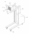
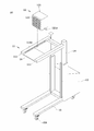
도 1은 본 발명의 실시예에 따른 스태커를 설명하기 위해 도시한 도면.
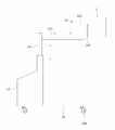
도 2는 도 1에 도시된 진공 흡착 장치가 분리된 상태를 도시한 도면.
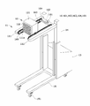
도 3은 도 1에 도시된 진공 흡착 장치에 의해 제품 박스가 진공 흡착된 상태를 도시한 도면.
도 4는 본 발명의 실시예에 따른 스태커의 동작 특성을 설명하기 위해 도시한 도면들.
도 5는 도 1에 도시된 진공 흡착 장치를 이송하기 위한 이송 수단의 일례를 설명하기 위해 이송 수단이 장착된 스태커를 도시한 도면.
도 6은 도 5에 도시된 진공 흡착 장치가 분리된 상태를 도시한 도면.
도 7은 도 5에 도시된 진공 흡착 장치가 포크부를 따라 전후방으로 이송하는 과정을 설명하기 위해 도시한 도면.
도 8은 본 발명의 실시예에 따른 스태커의 동작 특성을 설명하기 위해 도시한 도면들.
도 9는 본 발명의 다른 예에 따른 진공 흡착 장치를 설명하기 위해 도시한 도면.
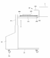
도 10은 본 발명의 다른 실시예에 따른 스태커를 설명하기 위해 도시한 도면.1 is a view illustrating a stacker according to an embodiment of the present invention.
Figure 2 is a view showing a state in which the vacuum adsorption apparatus shown in Figure 1 is separated.
3 is a view illustrating a state in which a product box is vacuum-adsorbed by the vacuum adsorption device shown in FIG. 1.
4 is a view showing for explaining the operation characteristics of the stacker according to an embodiment of the present invention.
FIG. 5 is a view showing a stacker equipped with a conveying means for explaining an example of the conveying means for conveying the vacuum adsorption device shown in FIG. 1; FIG.
6 is a view showing a state in which the vacuum adsorption apparatus shown in FIG. 5 is separated.
FIG. 7 is a view illustrating a process of transporting the vacuum adsorption device shown in FIG. 5 back and forth along the fork part. FIG.
8 is a view for explaining the operation characteristics of the stacker according to an embodiment of the present invention.
9 is a view for explaining a vacuum adsorption apparatus according to another embodiment of the present invention.
10 is a view illustrating a stacker according to another embodiment of the present invention.
본 발명의 이점 및 특징, 그리고 그것들을 달성하는 방법은 첨부되는 도면과 함께 상세하게 후술되는 실시예를 참조하면 명확해질 것이다. 그러나, 본 발명은 이하에서 개시되는 실시예로 한정되는 것이 아니라 서로 다른 다양한 형태로 구현될 것이다. Advantages and features of the present invention, and methods for achieving them will be apparent with reference to the embodiments described below in detail with the accompanying drawings. However, the present invention is not limited to the embodiments disclosed below, but may be implemented in various different forms.
본 명세서에서 본 실시예는 본 발명의 개시가 완전하도록 하며, 본 발명이 속하는 기술 분야에서 통상의 지식을 가진 자에게 발명의 범주를 완전하게 알려주기 위해 제공되는 것이다. 그리고 본 발명은 청구항의 범주에 의해 정의될 뿐이다. 따라서, 몇몇 실시예에서, 잘 알려진 구성 요소, 잘 알려진 동작 및 잘 알려진 기술들은 본 발명이 모호하게 해석되는 것을 피하기 위하여 구체적으로 설명되지 않는다. In this specification, the embodiments are provided so that the disclosure of the present invention may be completed and the scope of the present invention may be completely provided to those skilled in the art. And the present invention is defined only by the scope of the claims. Thus, in some embodiments, well known components, well known operations and well known techniques are not described in detail in order to avoid obscuring the present invention.
또한, 명세서 전체에 걸쳐 동일 참조 부호는 동일 구성 요소를 지칭한다. 그리고, 본 명세서에서 사용된(언급된) 용어들은 실시예를 설명하기 위한 것이며 본 발명을 제한하고자 하는 것은 아니다. 본 명세서에서, 단수형은 문구에서 특별히 언급하지 않는 한 복수형도 포함한다. 또한, '포함(또는, 구비)한다'로 언급된 구성 요소 및 동작은 하나 이상의 다른 구성요소 및 동작의 존재 또는 추가를 배제하지 않는다. Also, like reference numerals refer to like elements throughout. In addition, the terms used (discussed) herein are for the purpose of describing the embodiments are not intended to limit the invention. In this specification, the singular also includes the plural unless specifically stated otherwise in the phrase. In addition, components and operations referred to as 'includes (or includes)' do not exclude the presence or addition of one or more other components and operations.
다른 정의가 없다면, 본 명세서에서 사용되는 모든 용어(기술 및 과학적 용어를 포함)는 본 발명이 속하는 기술분야에서 통상의 지식을 가진 자에게 공통적으로 이해될 수 있는 의미로 사용될 수 있을 것이다. 또 일반적으로 사용되는 사전에 정의되어 있는 용어들은 정의되어 있지 않은 한 이상적으로 또는 과도하게 해석되지 않는다.Unless otherwise defined, all terms used in the present specification (including technical and scientific terms) may be used in a sense that can be commonly understood by those skilled in the art. In addition, the terms defined in the commonly used dictionary are not ideally or excessively interpreted unless they are defined.
이하, 첨부된 도면들을 참조하여 본 발명의 기술적 특징을 구체적으로 설명하기로 한다.Hereinafter, technical features of the present invention will be described in detail with reference to the accompanying drawings.
도 1은 본 발명의 실시예에 따른 스태커를 설명하기 위해 도시한 도면이고, 도 2는 도 1에 도시된 진공 흡착 장치가 분리된 상태를 도시한 도면이고, 도 3은 도 1에 도시된 진공 흡착 장치에 의해 제품 박스가 진공 흡착된 상태를 도시한 도면이다. 1 is a view illustrating a stacker according to an embodiment of the present invention, Figure 2 is a view showing a state in which the vacuum adsorption apparatus shown in Figure 1 is separated, Figure 3 is a vacuum shown in Figure 1 It is a figure which shows the state in which the product box was vacuum-sucked by the adsorption apparatus.
도 1 및 도 3을 참조하면, 본 발명의 실시예에 따른 스태커(10)는 포크부(11)를 구성하는 한 쌍의 포크(111) 사이에 슬라이딩 가능하게 설치되어 각종 물품이 포장된 제품 박스(1)를 진공 흡착 방식으로 흡착하는 진공 흡착 장치(12)를 포함한다. 1 and 3, the
진공 흡착 장치(12)는 한 쌍의 포크(111)를 따라 슬라이딩 가능하게 설치되는 진공 흡착 본체(121)와, 진공 흡착 본체(121)의 일측부에 설치되어 진공압을 이용하여 제품 박스(1)를 진공 흡착하는 적어도 하나의 진공 흡착 패드(122)를 포함한다. The
진공 흡착 본체(121)의 양측부 하단에는 각각 레일편(121a)이 형성되어 있다.
레일편(121a)은 도 1 및 도 2와 같이, 한 쌍의 포크(111)의 내측면(즉, 한 쌍의 포크(111)가 서로 대향하는 내측면)에 길이방향으로 형성된 레일홈(111a)에 삽입되어 슬라이딩 결합된다. 이에 따라, 진공 흡착 본체(121)는 레일홈(111a)에 결합된 레일편(121a)을 통해 한 쌍의 포크(111)의 길이방향으로 슬라이딩 이동한다. 1 and 2, the
포크부(11)는 도 1과 같이, 적재물을 적재하는 것으로, 스태커 본체(13)의 내부에 내장된 구동부(미도시)를 통해 승강 지지대(14)를 따라 상하방향으로 승강한다. The
이러한 포크부(11)는 도 1 및 도 2와 같이, 서로 나란하게 돌출된 한 쌍의 포크(111)를 포함한다. 이때, 한 쌍의 포크(111)는 전방측 종단부가 사각 바(bar) 형태로 이루어질 수 있다. 이에 따라, 진공 흡착 장치(12)를 이용하여 복수 개가 적층된 제품 박스들(1) 중 최상단에 적재된 제품 박스를 흡착할 때 한 쌍의 포크(111)의 전방측 종단부가 그 하부에 적재된 제품 박스(최상단에 적재된 제품 박스의 하부에 적재된 제품 박스)에 면접촉(스토퍼 기능)됨으로써 하부에 적재된 제품 박스는 흡착 대상 박스인 최상단에 적재된 제품 박스와 함께 진공 흡착되지 않는다. The
승강 지지대(14)는 다리부(15)로부터 수직으로 세워진 구조로 이루어져 포크부(11)를 지지하는 것으로, 포크부(11)가 고정 설치된 상태에서 승강 지지대(14)가 상기 구동부에 의해 스태커 본체(13)로부터 승강하여 포크부(11)를 상하로 승강시킨다. 물론, 이는 일례로서, 승강 지지대(14)는 고정된 상태로 스태커 본체(13)에 설치된 상태에서 승강 지지대(14)에 포크부(11)가 슬라이딩 가능하게 결합된 후 상기 구동부에 의해 승강 지지대(14)를 따라 상하방향으로 슬라이딩 이동될 수도 있다. The lifting
다리부(15)는 스태커(10)를 지면에 지지하기 위한 것으로, 지면 상에서 자유롭게 이동 가능하도록 지면과 맞닿는 부위에 복수 개의 휠(151)이 설치되어 있다. 이때, 휠(151)은 전방측과 후방측에 각각 설치될 수 있으며, 브레이크가 구비될 수 있다. The
한편, 도 1 내지 도 3에 도시된 본 발명의 실시예에 따른 스태커(10)를 구성하는 포크부(11), 진공 흡착 장치(12), 스태커 본체(13), 승강 지지대(14) 및 다리부(15)의 형상은 일례로서, 각각의 기능을 구현하는 범위 내에서 다양한 형상으로 변경될 수 있다. Meanwhile, the
도 4는 본 발명의 실시예에 따른 스태커의 동작 특성을 설명하기 위해 도시한 도면들로서, 적재되어 있는 제품 박스를 하역하는 과정을 각 단계별로 설명하기 위해 도시한 도면들이다. FIG. 4 is a diagram illustrating operation characteristics of a stacker according to an exemplary embodiment of the present invention. FIG. 4 is a diagram illustrating each step of a process of unloading a stacked product box.
도 4를 참조하면, 하역, 즉 운반하고자 하는 제품 박스(1)가 적재되어 있는 위치로 스태커(10)를 인력(또는 전동)으로 이동시킨 후 스태커 본체(13)의 내부에 구성된 구동부를 통해 포크부(11)를 승강 지지대(14)를 따라 운반하고자 하는 제품 박스(1)를 흡착할 적합한 위치로 승강시킨다. 이때, 포크부(11)는 진공 흡착 장치(12)의 진공 흡착패드(122)가 수평방향으로 제품 박스(1)와 정렬되도록 승강한다. Referring to Figure 4, unloading, that is, moving the
이후, 진공 흡착 장치(12)를 전방, 즉 운반 대상 제품 박스(1)로 근접하는 방향으로 이동시킨 후 진공 흡착 패드(122)가 운반 대상 제품 박스(1)에 일면에 맞닿도록 위치시킨다. Thereafter, the
이후, 진공 흡착 장치(12)를 구동시켜 운반 대상 제품 박스(1)를 진공 흡착 패드(122)를 이용하여 진공 흡착한다. 이때, 운반 대상 제품 박스(1)의 하부에 적재된 물품 박스는 한 쌍의 포크(111)의 종단부에 면 접촉됨에 따라 운반 대상 제품 박스(1)가 진공 흡착되는 과정에서 함께 이동되지 않고 적재된 상태 그대로 유지된다. Thereafter, the
이후, 진공 흡착 패드(122)를 통해 운반 대상 제품 박스(1)를 흡착한 상태로 포크부(11)를 따라 후방으로 슬라이딩 이동시킨 후 하부로 하강시켜 이송한다. 이때, 진공 흡착 장치(12)의 구동을 정지시켜 진공 흡착 상태를 제거한 상태로 운반 대상 제품 박스(1)를 포크부(11)의 상부에 안착시켜 제품 박스(1)를 하강 이송할 수도 있다. Subsequently, in the state in which the transport
이후, 스태커(10)를 운전하여 운반 장소(하역 장소)로 운반 대상 제품 박스(1)를 운반한다. Thereafter, the
한편, 진공 흡착 장치(12)는 이동 수단에 의해 포크부(11)를 따라 전후방으로 슬라이딩 이동된다. 이때, 이동 수단은 체인 방식이나 유압 방식으로 이루어질 수 있다. On the other hand, the
도 5는 도 1에 도시된 진공 흡착 장치를 이송하기 위한 이송 수단의 일례를 설명하기 위해 이송 수단이 장착된 스태커를 도시한 도면이고, 도 6은 도 5에 도시된 진공 흡착 장치가 분리된 상태를 도시한 도면이고, 도 7은 도 5에 도시된 진공 흡착 장치가 포크부를 따라 전후방으로 이송하는 과정을 설명하기 위해 도시한 도면이다. FIG. 5 is a view illustrating a stacker equipped with a transfer unit for explaining an example of a transfer unit for transferring the vacuum adsorption apparatus illustrated in FIG. 1, and FIG. 6 is a state in which the vacuum adsorption apparatus illustrated in FIG. 5 is separated. 7 is a view illustrating a process of transporting the vacuum adsorption device shown in FIG. 5 back and forth along the fork part.
도 5 내지 도 7을 참조하면, 이동 수단(16)이 체인 방식으로 이루어진 경우 구동모터(161), 기어박스(162), 체인(163), 구동 스프로킷(164) 및 종동 스프로킷(165)을 포함할 수 있다. 5 to 7, when the moving means 16 is formed in a chain manner, the driving
구동모터(161)는 기어박스(162)를 통해 구동 스프로킷(164)으로 구동력을 전달한다.The driving
도 5 및 도 6에는 구동모터(161)가 포크부(11)의 상부에 설치되어 있으나, 이는 설명의 편의를 위한 것으로, 포크부(11)의 승강 동작에 간섭되지 않도록 스태커(10)에 설치될 수 있다. 예를 들어, 별도의 기어부와 동력 전달부(체인)를 사용하여 스태커 본체(13)에 설치되거나, 혹은 스태커 본체(13)의 내부에 설치될 수도 있다. 이외에도, 적재물과 간섭되지 않는 범위 내에서 스태커(10)의 일측에 설치될 수 있다. 5 and 6, the
체인(163)은 구동 스프로킷(164)과 종동 스프로킷(165)을 상호 연결하여 구동 스프로킷(164)과 종동 스프로킷(165) 사이에 무한 궤도를 형성하고, 적어도 일측부가 브라켓(121b)을 통해 진공 흡착 장치(12), 즉, 진공 흡착 본체(121)의 일측부에 고정된다. 이에 따라, 진공 흡착 장치(12)는 체인(163)과 연동하여 전후방으로 이동된다. The
종동 스프로킷(165)은 포크부(11)의 종단부, 즉, 한 쌍의 포크(111) 중 적어도 어느 하나의 종단부에 설치될 수 있다. 이러한 종동 스프로킷(165)은 체인(163)을 팽팽하게 유지하기 위해 포크부(11)의 종단부에 전후방으로 이동가능하게 설치될 수 있다. The driven
도 5 및 도 6에는 이동 수단(16)의 구동 스프로킷(164)과 종동 스프로킷(165)이 한 쌍의 포크(111)의 양측에 설치되어 있으나, 이 또한 일례로서, 구동 스프로킷(164)과 종동 스프로킷(165)은 한 쌍의 포크(111) 중 어느 하나에만 설치될 수 있다. 5 and 6, the
한편, 한 쌍의 포크(111)의 전방측 종단부와 후방측 종단부에는 진공 흡착 장치(12)의 이동을 제한하는 리미트 스위치(미도시)가 더 설치될 수 있다. 상기 리미트 스위치는 구동모터(161)의 동작을 제어한다. 예를 들면, 진공 흡착 본체(121)가 전방측으로 이동하여 한 쌍의 포크(111)의 전방측에 설치된 상기 리미트 스위치가 턴-온(turn-ON)되면, 구동모터(161)는 구동이 정지되고, 진공 흡착 본체(121)가 후방측으로 이동하여 후방측에 설치된 상기 리미트 스위치가 턴-온(turn-ON) 되면 구동모터(161)는 동작을 정지하여 체인(163)이 역방향으로 회전하는 것을 차단한다. On the other hand, a limit switch (not shown) for restricting the movement of the
도 8은 본 발명의 실시예에 따른 스태커의 동작 특성을 설명하기 위해 도시한 도면들로서, 복수 개의 물품 박스들이 수직으로 적층된 상태로 적재되어 있는 상태에서 최상단 물품 박스를 하역하는 과정을 각 단계별로 설명하기 위해 도시한 도면들이다. 8 is a view illustrating the operation characteristics of the stacker according to an embodiment of the present invention, each step of the step of unloading the uppermost article box in a state where a plurality of article boxes are stacked in a vertically stacked state The drawings are shown for explanation.
도 8을 참조하면, 하역, 즉 운반하고자 하는 제품 박스(1)가 적재되어 있는 위치로 스태커(10)를 인력(또는 전동)으로 이동시킨 후 스태커 본체(13)의 내부에 구성된 구동부를 통해 포크부(11)를 승강 지지대(14)를 따라 운반 대상 제품 박스(1)를 흡착할 적합한 위치로 승강시킨다. 이때, 포크부(11)는 진공 흡착 장치(12)의 진공 흡착패드(122)가 수평방향으로 운반 대상 제품 박스(1)와 정렬되도록 승강한다. Referring to FIG. 8, unloading, that is, moving the
이후, 이동 수단(16)의 구동모터(161)를 구동시켜 포크부(11)를 따라 진공 흡착 장치(12)를 전방, 즉 운반 대상 제품 박스(1)로 근접하는 방향으로 슬라이딩 이동시킨다. 이때, 진공 흡착 패드(122)가 운반 대상 제품 박스(1)에 일면에 맞닿도록 위치시킨다. Thereafter, the driving
이후, 진공 흡착 장치(12)를 구동시켜 운반 대상 제품 박스(1)를 진공 흡착 패드(122)를 이용하여 진공 흡착한 후 진공 흡착 패드(122)를 통해 운반 대상 제품 박스(1)를 흡착한 상태로 포크부(11)를 따라 후방으로 슬라이딩 이동시킨 후 하부로 하강시켜 이송한다. Thereafter, the
이후, 스태커(10)를 운전하여 운반 장소로 운반 대상 제품 박스(1)를 운반한다. Thereafter, the
한편, 이동 수단(16)은 도시되어 있지는 않지만, 체인 방식이 아닌 유압 방식이 적용될 수 있다. On the other hand, although the moving means 16 is not shown, a hydraulic method, not a chain method, may be applied.
유압 방식으로 이루어진 이동 수단은 스태커(10) 또는 진공 흡착 장치(12)의 본체(121)에 설치된 유압 실린더와, 상기 유압 실린더에서 출몰하는 로드를 포함한다. 이때, 전자의 경우 상기 로드는 진공 흡착 본체(121)의 후면부에 체결되고, 후자의 경우에는 한 쌍의 포크(111)의 후방측 연결하는 연결부에 체결될 수 있다. 이에 따라 상기 로드가 상기 유압 실린더에 의해 전후방으로 출몰하면, 이와 연동하여 진공 흡착 본체(121)는 한 쌍의 포크(111)를 따라 전후방으로 슬라이딩 이동하게 된다. The moving means made by the hydraulic method includes a hydraulic cylinder installed in the
도 9는 본 발명의 다른 예에 따른 진공 흡착 장치를 설명하기 위해 도시한 도면이다. 9 is a view illustrating a vacuum adsorption device according to another embodiment of the present invention.
도 9를 참조하면, 본 발명의 다른 예에 따른 진공 흡착 장치(22)는 진공 흡착 패드(222)의 하부에 압축 공기를 전방으로 분사는 압축 공기 분사노즐(223)이 설치된다. 9, in the
압축 공기 분사노즐(223)은 진공 흡착 패드(222)가 형성된 진공 흡착 본체(221)의 전방측 최하부에 복수 개가 설치되어 제품 박스(1)로 강한 압축 공기를 분사한다. 즉, 상하로 적재되어 있는 제품 박스(1)들 사이(틈새)를 강한 압축 공기로 들뜨게 하고, 이를 통해 제품 박스(1) 간의 분리가 용이하여 진공 흡착 패드(222)를 통한 진공 흡착시 제품 박스(1)를 보다 용이하게 흡착하여 이송할 수 있다. The plurality of compressed
또한, 진공 흡착 본체(221)에는 제품 박스(1) 간의 사이의 틈새를 감지하기 위해 정렬센서(미도시)가 더 설치될 수 있다. 이를 통해 제품 박스(1)들 사이의 틈새를 정확하게 감지하여 압축 공기 분사노즐(223)을 통해 정확한 위치에 압축 공기를 분사할 수 있다. In addition, an alignment sensor (not shown) may be further installed in the
도 10은 본 발명의 다른 실시예에 따른 스태커를 설명하기 위해 도시한 도면으로서, 도 2와 같이, 진공 흡착 장치(12)가 포크부(11)로부터 분리된 상태를 도시한 도면이다. FIG. 10 is a view illustrating a stacker according to another embodiment of the present invention. As shown in FIG. 2, the
도 10을 참조하면, 본 발명의 다른 실시예에 따른 스태커(20)는 도 1 및 도 2에 도시된 스태커(10)와 마찬가지로, 포크부(11), 진공 흡착 장치(12), 스태커 본체(13), 승강 지지대(14) 및 다리부(15)를 포함한다. 또한 도시되어 있지는 않지만, 도 6에 도시된 이송 수단을 더 포함할 수 있다. 그리고, 본 발명의 실시예에 따른 스태커(20)는 포크부(11)의 한 쌍의 포크(111) 사이에 받침판(21)이 설치된다. Referring to FIG. 10, the
이러한 받침판(21)은 진공 흡착 장치(12)의 흡착력에 비해 진공 흡착 장치(12)에 흡착되는 물품 또는 제품 박스의 하중이 무거워 진공 흡착 장치(12)에 흡착된 물품 또는 제품 박스를 진공 흡착하여 이송하는 과정에서 낙하하는 것을 방지하기 위해 설치된다. Since the
이를 위해 받침판(21)은 한 쌍의 포크(111)에 형성된 레일홈(111a)의 하부에 고정 설치되거나, 혹은 착탈 가능하게 설치될 수 있다. 그리고, 받침판(21)은 판체 형상으로 이루어지고, 그 상부면에는 진공 흡착 장치(12)에 흡착된 물품 또는 제품 박스의 하부가가 미끄러지거나 이탈되는 것을 방지하기 위해 합성수지재질의 미끄럼 및 이탈 방지부재가 추가로 코팅되어 있거나, 혹은 별도로 접착방식으로 설치될 수 있다.To this end, the
이상에서와 같이 본 발명의 기술적 사상은 바람직한 실시예에서 구체적으로 기술되었으나, 상기한 바람직한 실시예는 그 설명을 위한 것이며, 그 제한을 위한 것이 아니다. 이처럼 이 기술 분야의 통상의 전문가라면 본 발명의 기술 사상의 범위 내에서 본 발명의 실시예의 결합을 통해 다양한 실시예들이 가능함을 이해할 수 있을 것이다.As described above, the technical spirit of the present invention has been described in detail in the preferred embodiments, but the above-described preferred embodiments are for the purpose of description and not of limitation. As such, those skilled in the art may understand that various embodiments are possible through the combination of the embodiments of the present invention within the scope of the technical idea of the present invention.
10 : 스태커 11 : 포크부
12, 22 : 진공 흡착 장치 13 : 스태커 본체
14 : 승강 지지대 15 : 다리부
16 : 이송 수단 111 : 한 쌍의 포크
111a : 레일홈 121, 221 : 진공 흡착 본체
122, 222 : 진공 흡착 패드 121a : 레일편
121b : 브라켓 151 : 휠
161: 구동모터 162 : 기어박스
163 : 체인 164 : 구동 스프로킷
165 : 종동 스프로킷 223 : 압축 공기 분사노즐
21 : 받침판
10: stacker 11: fork portion
12, 22: vacuum adsorption device 13: stacker body
14 lifting support 15: leg portion
16: conveying means 111: a pair of forks
111a:
122, 222:
121b: Bracket 151: Wheel
161: drive motor 162: gearbox
163: chain 164: drive sprocket
165: driven sprocket 223: compressed air injection nozzle
21: support plate
Claims (7)
상기 스태커 본체를 지면에 지지하는 다리부;
상기 다리부에서 수직으로 세워진 승강 지지대;
상기 승강 지지대를 따라 승강하거나 상기 승강 지지대와 함께 승강하는 포크부; 및
상기 포크부를 구성하는 한 쌍의 포크 사이에 설치되고, 상기 한 쌍의 포크의 길이방향으로 슬라이딩 이동하며, 제품 박스를 진공 흡착하여 이송하는 진공 흡착 장치;
를 포함하는 것을 특징으로 하는 진공 흡착 장치가 구비된 스태커.
Stacker body;
A leg portion supporting the stacker body on the ground;
Lifting support vertically erected from the leg portion;
A fork portion which is lifted along the lift support or lifted with the lift support; And
A vacuum adsorption device installed between the pair of forks constituting the fork portion, and slidingly moving in the longitudinal direction of the pair of forks, and vacuum adsorbing the product box;
Stacker is provided with a vacuum adsorption device comprising a.
상기 진공 흡착 장치는,
상기 한 쌍의 포크를 따라 슬라이딩 가능하게 설치되는 진공 흡착 본체; 및
상기 진공 흡착 본체의 일측부에 설치되어 진공압을 이용하여 상기 제품 박스를 진공 흡착하는 적어도 하나의 진공 흡착 패드; 를 포함하되,
상기 진공 흡착 본체의 양측부 하단에는 각각 레일편이 형성되어 있고, 상기 레일편은 상기 한 쌍의 포크의 내측면에 길이방향으로 형성된 레일홈에 슬라이딩 결합되는,
것을 특징으로 하는 진공 흡착 장치가 구비된 스태커.
The method of claim 1,
The vacuum adsorption device,
A vacuum suction body slidably installed along the pair of forks; And
At least one vacuum adsorption pad installed at one side of the vacuum adsorption body for vacuum adsorption of the product box using a vacuum pressure; Including but not limited to:
Rail pieces are formed at lower ends of both sides of the vacuum suction body, and the rail pieces are slidably coupled to rail grooves formed in the longitudinal direction on the inner surfaces of the pair of forks.
Stacker having a vacuum adsorption device, characterized in that.
상기 포크부 또는 상기 스태커 본체에 설치되어 상기 진공 흡착 장치를 상기 한 쌍의 포크의 길이방향으로 이동시키는 이송 수단을 더 포함하는 것을 특징으로 하는 진공 흡착 장치가 구비된 스태커.
The method according to claim 1 or 2,
Stacker with a vacuum adsorption device, characterized in that it further comprises a transfer means installed in the fork portion or the stacker body to move the vacuum adsorption device in the longitudinal direction of the pair of forks.
상기 이송 수단은 체인 방식 또는 유압 방식으로 상기 진공 흡착 장치를 상기 한 쌍의 포크의 길이방향으로 이동시키는 것을 특징으로 하는 진공 흡착 장치가 구비된 스태커.
The method of claim 3, wherein
The transfer means is a stacker with a vacuum adsorption device, characterized in that for moving the vacuum adsorption device in the longitudinal direction of the pair of forks in a chain or hydraulic manner.
상기 진공 흡착 장치는 상기 진공 흡착 패드가 설치된 상기 진공 흡착 본체의 전방측 최하부에 복수 개가 설치되어 상기 제품 박스로 강한 압축 공기를 분사하는 압축 공기 분사노즐을 더 포함하는 것을 특징으로 하는 진공 흡착 장치가 구비된 스태커.
The method of claim 2,
The vacuum adsorption device further comprises a compressed air jet nozzle which is installed at the lowermost front side of the vacuum adsorption body in which the vacuum adsorption pad is installed to inject strong compressed air into the product box. Equipped stacker.
상기 진공 흡착 장치는 상기 진공 흡착 본체에 설치되어 상기 제품 박스 간의 사이의 틈새를 감지하는 정렬센서를 더 포함하는 것을 특징으로 하는 진공 흡착 장치가 구비된 스태커.
The method of claim 5, wherein
The vacuum adsorption device is equipped with a vacuum adsorption device, characterized in that the vacuum adsorption device further comprises an alignment sensor installed in the vacuum adsorption body for detecting the gap between the product box.
판체로 이루어지고, 상기 한 쌍의 포크에 형성된 레일홈의 하부에 위치되도록 상기 한 쌍의 포크에 고정 설치되거나 착탈 가능하게 설치되어 상기 진공 흡착 장치의 흡착력에 비해 진공 흡착 장치에 흡착되는 제품 박스의 하중이 무거워 상기 진공 흡착 장치에 흡착된 제품 박스를 진공 흡착하여 이송하는 과정에서 낙하하는 것을 방지하는 받침판을 더 포함하는 것을 특징으로 하는 진공 흡착 장치가 구비된 스태커.The method of claim 1,
The product box is made of a plate, fixed to the pair of forks to be located in the lower portion of the rail groove formed in the pair of forks or detachably installed to be adsorbed to the vacuum adsorption device compared to the adsorption force of the vacuum adsorption device Stacker is equipped with a vacuum adsorption device, characterized in that the load is heavy, further comprising a support plate to prevent falling in the process of vacuum suction and transport the product box adsorbed to the vacuum adsorption device.
Priority Applications (1)
| Application Number | Priority Date | Filing Date | Title |
|---|---|---|---|
| KR1020180095647A KR102088058B1 (en) | 2018-08-16 | 2018-08-16 | Stacker with a vacuum adsorption device |
Applications Claiming Priority (1)
| Application Number | Priority Date | Filing Date | Title |
|---|---|---|---|
| KR1020180095647A KR102088058B1 (en) | 2018-08-16 | 2018-08-16 | Stacker with a vacuum adsorption device |
Publications (2)
| Publication Number | Publication Date |
|---|---|
| KR20200020215A true KR20200020215A (en) | 2020-02-26 |
| KR102088058B1 KR102088058B1 (en) | 2020-03-11 |
Family
ID=69637802
Family Applications (1)
| Application Number | Title | Priority Date | Filing Date |
|---|---|---|---|
| KR1020180095647A KR102088058B1 (en) | 2018-08-16 | 2018-08-16 | Stacker with a vacuum adsorption device |
Country Status (1)
| Country | Link |
|---|---|
| KR (1) | KR102088058B1 (en) |
Families Citing this family (2)
| Publication number | Priority date | Publication date | Assignee | Title |
|---|---|---|---|---|
| KR102413897B1 (en) | 2020-06-09 | 2022-06-30 | 한국철도기술연구원 | cargo trasporting apparatus using multiple absorption gripper |
| KR102523374B1 (en) | 2022-11-28 | 2023-04-20 | (주)엔스퀘어 | High-efficiency logistics unloading system |
Citations (6)
| Publication number | Priority date | Publication date | Assignee | Title |
|---|---|---|---|---|
| KR940013651A (en) * | 1992-12-08 | 1994-07-15 | 이해규 | Heat box installation device |
| JPH08282989A (en) * | 1995-04-14 | 1996-10-29 | Nippon Sharyo Seizo Kaisha Ltd | Device for installation and carrying interior material |
| KR20100057242A (en) * | 2008-11-21 | 2010-05-31 | 한전케이피에스 주식회사 | Apparatus for pulling up the electroytic cell |
| KR101816715B1 (en) | 2016-09-06 | 2018-01-09 | 강용주 | Stacker for bifacial pallet |
| KR20180062852A (en) | 2016-12-01 | 2018-06-11 | 한전케이피에스 주식회사 | Heigh limit apparatus for forklift of portable electric stacker |
| JP2018089721A (en) * | 2016-11-30 | 2018-06-14 | 株式会社東芝 | Article moving device, and control method of the same |
-
2018
- 2018-08-16 KR KR1020180095647A patent/KR102088058B1/en active IP Right Grant
Patent Citations (6)
| Publication number | Priority date | Publication date | Assignee | Title |
|---|---|---|---|---|
| KR940013651A (en) * | 1992-12-08 | 1994-07-15 | 이해규 | Heat box installation device |
| JPH08282989A (en) * | 1995-04-14 | 1996-10-29 | Nippon Sharyo Seizo Kaisha Ltd | Device for installation and carrying interior material |
| KR20100057242A (en) * | 2008-11-21 | 2010-05-31 | 한전케이피에스 주식회사 | Apparatus for pulling up the electroytic cell |
| KR101816715B1 (en) | 2016-09-06 | 2018-01-09 | 강용주 | Stacker for bifacial pallet |
| JP2018089721A (en) * | 2016-11-30 | 2018-06-14 | 株式会社東芝 | Article moving device, and control method of the same |
| KR20180062852A (en) | 2016-12-01 | 2018-06-11 | 한전케이피에스 주식회사 | Heigh limit apparatus for forklift of portable electric stacker |
Also Published As
| Publication number | Publication date |
|---|---|
| KR102088058B1 (en) | 2020-03-11 |
Similar Documents
| Publication | Publication Date | Title |
|---|---|---|
| KR101857347B1 (en) | Uumaned Truck for Roll Product Transferring | |
| KR101877653B1 (en) | Conveyance system for object to be conveyed and conveyance method | |
| US2468055A (en) | Load-dumping pallet | |
| EP1879822B1 (en) | System for unloading or loading of cargo | |
| JP2620707B2 (en) | Lift-spoke type cargo handling equipment | |
| US20060280580A1 (en) | Line feed system with indexing cart | |
| CN107032141B (en) | Mobile robot capable of automatically loading and unloading goods | |
| US20170369295A1 (en) | Load manipulator | |
| KR102088058B1 (en) | Stacker with a vacuum adsorption device | |
| KR20110035040A (en) | Conveyor pallet for forklift | |
| CN108025755A (en) | The method and conveying arrangement of counter or tray of the transport with aviation goods | |
| JP2018521931A (en) | Apparatus and method for conveying a conveyed product | |
| JP2010089932A (en) | Transport device using carriage | |
| US10023403B2 (en) | Pallet handling | |
| JP3877755B2 (en) | Conveying device for transported material, method for carrying out transported material from transport container using the same, and method for loading transported material into transport container | |
| CN218465012U (en) | Stacking device in compartment | |
| JP2014101206A (en) | Transfer device | |
| JP5509833B2 (en) | Carry-in / out device | |
| JP7217139B2 (en) | Luggage carrier | |
| JPH09309697A (en) | Unloading attachment for forklift | |
| CN210736090U (en) | Logistics management vehicle transportation use device | |
| CN112407818B (en) | Carbon block packing and transporting trolley suitable for automatic packaging line and transporting method | |
| JPH06345397A (en) | Automated guided vehicle with transfer equipment | |
| JP4541079B2 (en) | Method for loading long objects on pallets for long objects and method for conveying long object pallets to transport containers | |
| JP2000191141A (en) | Article transfer device and article tiering device using it |
Legal Events
| Date | Code | Title | Description |
|---|---|---|---|
| A201 | Request for examination | ||
| E902 | Notification of reason for refusal | ||
| E701 | Decision to grant or registration of patent right | ||
| GRNT | Written decision to grant |