JP4541079B2 - Method for loading long objects on pallets for long objects and method for conveying long object pallets to transport containers - Google Patents
Method for loading long objects on pallets for long objects and method for conveying long object pallets to transport containers Download PDFInfo
- Publication number
- JP4541079B2 JP4541079B2 JP2004268823A JP2004268823A JP4541079B2 JP 4541079 B2 JP4541079 B2 JP 4541079B2 JP 2004268823 A JP2004268823 A JP 2004268823A JP 2004268823 A JP2004268823 A JP 2004268823A JP 4541079 B2 JP4541079 B2 JP 4541079B2
- Authority
- JP
- Japan
- Prior art keywords
- pallet
- long object
- long
- stage
- loading
- Prior art date
- Legal status (The legal status is an assumption and is not a legal conclusion. Google has not performed a legal analysis and makes no representation as to the accuracy of the status listed.)
- Active
Links
Images


Landscapes
- Pallets (AREA)
Description
本発明は、長尺物用パレットへの長尺物の積載方法並びに長尺物積載パレットの輸送容器への搬送方法に関し、さらに詳しくは、様々な種類、形状の長尺物を損傷させることなく安定的に且つ輸送費用を抑えて輸送することができる長尺物用パレットへの長尺物の積載方法並びに長尺物積載パレットの輸送容器への搬送方法に関する。 The present invention relates to a method for loading a long object on a long object pallet and a method for transporting a long object loading pallet to a transport container, and more particularly, without damaging various kinds and shapes of long objects. The present invention relates to a method for loading a long object on a long object pallet that can be transported stably and at a reduced transportation cost, and a method for transporting a long object loading pallet to a transport container.
従来より、長尺物(例えば、鋼製パイプ材)の輸送方法として、多数の長尺物を木箱で梱包し、その梱包貨物を輸送容器(例えば、ドライコンテナ等)内に収容して、その輸送容器を陸上、海上輸送等する方法が一般に行われている。
しかし、上記従来方法では、木箱を採用しているので、大量の木材を使用する必要があり、木箱自体が極めて高額であり、また木箱の製作に時間がかかり、全体の輸送費用が高騰してしまうといった問題があった。特に、軸方向長さの異なる長尺物を木箱で梱包するには、木箱内に詰め物をする必要があり、更に輸送費用が高騰していた。また、木箱を採用した輸送では、通常、40フィートドライコンテナに対して約9ton程度の長尺物が収容されており、輸送容器への積載効率が悪いものであった。
Conventionally, as a method of transporting long objects (for example, steel pipe materials), many long objects are packed in wooden boxes, and the packed cargo is accommodated in a transport container (for example, a dry container), A method of transporting the transport container on land or sea is generally performed.
However, since the above conventional method employs a wooden box, it is necessary to use a large amount of wood, the wooden box itself is extremely expensive, and it takes time to manufacture the wooden box, and the overall transportation cost is reduced. There was a problem of soaring. In particular, in order to pack long objects having different lengths in the axial direction in a wooden box, it is necessary to stuff the wooden box, and the transportation cost has further increased. Further, in transportation using a wooden box, normally, a long object of about 9 tons is accommodated in a 40-foot dry container, and the loading efficiency on the transportation container is poor.
そこで、上記問題を解決するために、木箱の替わりに、多数の長尺物を積載可能な長尺物用パレットを採用して、輸送費用を抑えて長尺物を輸送することが考えられる。この長尺物用パレットとしては、パレット本体と、このパレット本体の両側縁部に立設される支柱と、を備え、この支柱によって、パレット本体に並列且つ段積み状に積載される長尺物の荷崩れを防止するものが知られている(例えば、特許文献1〜3参照)。
Therefore, in order to solve the above problem, it is conceivable to use a long object pallet capable of loading a large number of long objects in place of the wooden box, and to transport the long objects at a low transportation cost. . As the pallet for long objects, a pallet main body and a column that is erected on both side edges of the pallet main body, and a long object that is stacked in parallel and stacked on the pallet main body by the column. Is known to prevent the collapse of the load (for example, see
ここで、上述のように、長尺物を積載してなる長尺物用パレットを輸送容器に収容した際、長尺物の軸方向と輸送容器の輸送方向(例えば、長手方向)とが一致しているため、輸送容器の輸送時に長尺物が軸方向に飛出してしまい、長尺物や輸送容器が損傷してしまう危険がある。しかし、上記特許文献1〜3には、積載された長尺物の軸方向への飛出しを防止する手段について何ら開示及び示唆されておらず、輸送容器の輸送時に長尺物や輸送容器が損傷してしまう恐れがあった。
また、上記特許文献1〜3では、多数の長尺物を互いに接触した状態で積重ねるようにしているので、長尺物用パレットへの長尺物の積載時や輸送容器の輸送時等に、長尺物同士の衝突、摩擦接触等により長尺物が損傷してしまう恐れがあった。
なお、輸送対象である長尺物の形状等は様々なものがあり、これらに対応して長尺物の軸方向への飛出しを防止できる手段の出現が望まれている。
Here, as described above, when the long object pallet formed by loading the long object is accommodated in the transport container, the axial direction of the long object and the transport direction (for example, the longitudinal direction) of the transport container are the same. Therefore, when transporting the transport container, there is a risk that the long object will fly out in the axial direction and the long object or the transport container may be damaged. However, the
In
There are various shapes of long objects to be transported, and in response to these, the emergence of means capable of preventing the long objects from jumping in the axial direction is desired.
また、上記特許文献1には、ドライコンテナに対して輸送貨物(長尺物積載パレット)を一度に搬送し得るように、(1)パレットの側面に設けられた張出部を持ち上げて搬送可能なスタドラルを備える形態(特許文献1の図5参照)、(2)パレットの下部に連繋されたワイヤロープを、滑車を介してフォークリフトで引き上げる形態(特許文献1の図8参照)等が開示されている。
しかし、上記(1)形態では、大型で且つ高価なストライドを用いる必要があり、やはり全体の輸送コストが高騰してしまうといった問題がある。また、上記(2)形態では、パレットの下面部とステージ及び輸送容器の床面とが摩擦接触され、パレット、ステージ、輸送容器の床面等が損傷してしまう等の問題がある。
また、ドライコンテナに長尺物積載パレットを搬入する場合、その長尺物積載パレットを真直ぐに(直進性を保って)搬送することが要求され、この要求が満たされないと、(a)ドライコンテナ内に傾いた状態で搬入された長尺物積載パレットが、その搬出の際に、ドライコンテナの内壁に擦って(摩擦接触)しまい搬出が極めて困難なものとなってしまう、(b)長尺物積載パレットがドライコンテナ内壁に衝突して、長尺物、パレット、ドライコンテナ等が損傷してしまう等の問題があった。しかしながら、上記特許文献1には、ドライコンテナに長尺物積載パレットを搬入する際のパレットの直進性を確保する手段について何ら開示及び示唆されていない。
以上より、ドライコンテナ(特に、40フィートドライコンテナ)に対して輸送貨物(長尺物積載パレット)を一度に搬送することができる現実的な搬送方法の出現が望まれている。
Moreover, in the above-mentioned
However, in the above-mentioned form (1), it is necessary to use a large and expensive stride, and there is a problem that the entire transportation cost is also increased. Further, in the form (2), there is a problem that the lower surface of the pallet and the stage and the floor surface of the transport container are brought into frictional contact, and the pallet, the stage, the floor surface of the transport container and the like are damaged.
Further, when a long object loading pallet is carried into a dry container, it is required to convey the long object loading pallet straight (maintaining straight movement). If this requirement is not satisfied, (a) a dry container The long object loading pallet loaded in a tilted state rubs against the inner wall of the dry container during the unloading (friction contact), and the unloading becomes extremely difficult. There was a problem that a long pallet, a pallet, a dry container, and the like were damaged due to an object loading pallet colliding with the inner wall of the dry container. However, the above-mentioned
From the above, the emergence of a realistic transport method capable of transporting transported cargo (elongated article pallet) at a time to a dry container (particularly a 40-foot dry container) is desired.
以上より本発明は、上記現状に鑑みてなされたものであり、様々な形状等の長尺物を損傷させることなく安定的に且つ輸送費用を抑えて輸送することができる長尺物用パレットへの長尺物の積載方法を提供することを目的とする。また、本発明は、上記長尺物用パレットへの長尺物の積載方法を用いてなされる長尺物積載パレットの輸送容器への好適な搬送方法を提供することを他の目的とする。 As described above, the present invention has been made in view of the above-described present situation, and to a pallet for long objects that can be transported stably and at low transportation costs without damaging long objects of various shapes and the like . An object of the present invention is to provide a method for loading long objects . Another object of the present invention is to provide a suitable method for transporting a long object loading pallet to a transport container, which is performed using the above-described method for loading a long object on a long object pallet .
本発明は、以下の通りである。
1.複数の長尺物が並列され且つ段積みされた状態で輸送容器内に収容される長尺物用パレットへの長尺物の積載方法であって、
前記長尺物用パレットは、
パレット本体と、該パレット本体に前記長尺物の並列方向に所定間隔で立設される一対の支柱と、を備え、該一対の支柱は、該パレット本体に前記長尺物の軸方向に沿って複数設けられており、
前記一対の支柱の間には、前記長尺物が載置される載置部材が挿設され、該載置部材には、該載置部材に載置された該長尺物の軸方向への飛出しを防止する飛出し防止部材が設けられ、該飛出し防止部材が、前記載置部材の上に載置された前記長尺物の軸方向の端面に対向又は当接しており、
前記一対の支柱の間に前記載置部材の両端部を挿入して、該載置部材を所定の高さ位置に位置決めする工程〔a〕と、
所定の高さ位置に位置決めされた前記載置部材の上に前記長尺物を並列させると共に、所定の高さ位置に位置決めされた前記載置部材に前記飛出し防止部材を設けて、該飛出し防止部材を該載置部材の上に載置された前記長尺物の軸方向の端面に対向又は当接させる工程〔b〕と、を備え、
前記工程〔a〕及び前記工程〔b〕を必要に応じて繰り返し行い、
前記工程〔a〕は、前記載置部材が最下段用の載置部材である場合には、前記一対の支柱の間に該最下段用の載置部材の両端部を挿入して、該最下段用の載置部材を前記パレット本体の上に載置して所定の高さ位置に位置決めし、前記載置部材が最下段用以外の載置部材である場合には、前記一対の支柱の間に該最下段用以外の載置部材の両端部を挿入して、該最下段用以外の載置部材を、積載された前記長尺物の上に載置させて所定の高さ位置に位置決めする工程であり、
前記工程〔b〕は、所定の高さ位置に位置決めされた前記載置部材の上に前記長尺物を並列させると共に、前記一対の支柱の間に前記飛出し防止部材の両端部を挿入して、該飛出し防止部材を、所定の高さ位置に位置決めされた前記載置部材に載置して該載置部材の上に載置された前記長尺物の軸方向の端面に対向又は当接させ、更に最上段用の飛出し防止部材の両端部を固定手段により前記一対の支柱に固定させる工程であることを特徴とする長尺物用パレットへの長尺物の積載方法。
2.前記飛出し防止部材が、前記一対の支柱の間に挿入されて前記載置部材の上に載置されている上記1.記載の長尺物用パレットへの長尺物の積載方法。
3.前記載置部材及び前記飛出し防止部材が、前記長尺物の並列方向に延びる長尺状になされ、前記支柱が、該一対の支柱の間に挿入される前記載置部材の長尺方向の両端部を上下方向に案内する第1案内部と、該一対の支柱の間に挿入される前記飛出し防止部材の長尺方向の両端部を上下方向に案内する第2案内部と、を有する上記2.記載の長尺物用パレットへの長尺物の積載方法。
4.前記支柱が、横断面コの字状になされ、且つ、前記第1案内部としての案内溝と、前記飛出し防止部材の長尺方向の両端部に形成された切欠部を上下方向に案内する前記第2案内部としての案内片と、を有する上記3.記載の長尺物用パレットへの長尺物の積載方法。
5.前記一対の支柱が、第1長尺物に対応して設けられる一対二組の第1支柱と、該第1長尺物より軸方向長さの短い第2長尺物に対応して設けられる一対二組の第2支柱と、を有する上記1.乃至4.のいずれか一項に記載の長尺物用パレットへの長尺物の積載方法。
6.前記一対の第1支柱の二組が、前記パレット本体の前後方向の中心から前後対称に配設され、前記一対の第2支柱の二組が、前記パレット本体の前後方向の中心から前後対称に配設されている上記5.記載の長尺物用パレットへの長尺物の積載方法。
7.前記載置部材が角材よりなされ、前記飛出し防止部材及び前記支柱が鋼材よりなされている上記1.乃至6.のいずれか一項に記載の長尺物用パレットへの長尺物の積載方法。
8.前記載置部材が、該載置部材に載置された前記長尺物の横方向への移動を防止する横移動防止部を有する上記1.乃至7.のいずれか一項に記載の長尺物用パレットへの長尺物の積載方法。
9.前記輸送容器がドライコンテナである上記1.乃至8.のいずれか一項に記載の長尺物用パレットへの長尺物の積載方法。
10.前記飛出し防止部材は、前記一対の支柱の間に挿入されて前記載置部材の上に載置されており、
前記載置部材及び前記飛出し防止部材は、前記長尺物の並列方向に延びる長尺状になされ、前記支柱が、該一対の支柱の間に挿入される前記載置部材の長尺方向の両端部を上下方向に案内する第1案内部と、該一対の支柱の間に挿入される前記飛出し防止部材の長尺方向の両端部を上下方向に案内する第2案内部と、を有し、
前記支柱は、横断面コの字状になされ、且つ、前記第1案内部としての案内溝と、前記飛出し防止部材の長尺方向の両端部に形成された切欠部を上下方向に案内する前記第2案内部としての案内片と、を有し、
前記載置部材は角材よりなされ、前記飛出し防止部材及び前記支柱は鋼材よりなされており、
前記載置部材は、該載置部材に載置された前記長尺物の横方向への移動を防止する横移動防止部を有し、
前記輸送容器はドライコンテナである上記1.記載の長尺物用パレットへの長尺物の積載方法。
11.上記1.乃至10.のいずれか一項に記載の長尺物用パレットへの長尺物の積載方法を用いてなされる長尺物積載パレットの輸送容器への搬送方法であって、
前記長尺物用パレットの前記パレット本体の下側には、下方及び該パレット本体の前後方向を開放してなる下部開放空間が形成されており、
所定位置の前記輸送容器の一端開口部に近接するステージの床面上に、前記長尺物用パレットの前記下部開放空間を構成する底面を水平移動自在に支持する第1滑動体と、該第1滑動体を昇降させる第1昇降体とを備える第1昇降滑動装置を用意すると共に、
所定位置の前記輸送容器の床面上に、前記長尺物用パレットの前記下部開放空間を構成する底面を水平移動自在に支持する第2滑動体と、該第2滑動体を昇降させる第2昇降体とを備える第2昇降滑動装置を用意し、
前記第1昇降滑動装置と前記第2昇降滑動装置との間で、複数の前記長尺物を積載してなる前記長尺物用パレットを、前記ステージ又は前記輸送容器の床面より浮上させた状態で水平移動させて受け渡すようにしたことを特徴とする長尺物積載パレットの輸送容器への搬送方法。
12.上記1.乃至10.のいずれか一項に記載の長尺物用パレットへの長尺物の積載方法を用いてなされる長尺物積載パレットの輸送容器への搬送方法であって、
前記長尺物用パレットの前記パレット本体の下側には、下方及び該パレット本体の前後方向を開放してなる下部開放空間が形成されており、
前記下部開放空間を構成する底面を支持するパレット支持部材と、該パレット支持部材を昇降させる昇降手段と、を有する床面上を走行可能な搬送台車を用意し、該搬送台車を、複数の前記長尺物を積載してなる前記長尺物用パレットの前記下部開放空間内に進入させ、前記昇降手段により上昇される前記パレット支持部材が前記底面を支持して前記長尺物用パレットを床面より浮上させ、その浮上状態で、該搬送台車を走行させて前記長尺物用パレットを水平方向に移送し、前記昇降手段により下降される前記パレット支持部材が前記底面の支持を解除して前記長尺物用パレットを床面上に載置させるようにしたことを特徴とする長尺物積載パレットの輸送容器への搬送方法。
13.前記搬送台車が走行する走行部、及び該走行部を走行する該搬送台車に設けた被案内部を案内する案内部が設けられ且つ床面上を走行可能な案内本体を有する案内具を用意し、先ず、前記搬送台車を搭載した状態の前記案内具を、所定位置の前記輸送容器の一端開口部に近接するステージの床面上に用意し、次に、前記案内具を、前記ステージ及び前記輸送容器の床面上を走行させて該輸送容器内に位置させ、次いで、前記ステージの床面上に複数の前記長尺物を積載してなる前記長尺物用パレットを載置し、その後、前記搬送台車を、前記案内具の前記走行部及び前記ステージの床面上を走行させて、前記長尺物用パレットの前記下部開放空間内に進入させた状態で該ステージ上に位置させ、次に、前記昇降手段により前記パレット支持部材を上昇させ、該パレット支持部材が前記底面を支持して前記長尺物用パレットを床面より浮上させ、次いで、前記搬送台車を、前記ステージ及び前記案内具の前記走行部の床面上を走行させて、浮上状態の前記長尺物用パレットを前記輸送容器内に位置させ、その後、前記昇降手段により前記パレット支持部材を下降させ、該パレット支持部材が前記底面の支持を解除して前記長尺物用パレットを前記輸送容器の床面上に載置させ、次に、前記搬送台車を搭載した状態の前記案内具を、前記輸送容器及び前記ステージの床面上を走行させて該ステージ上に位置させ、前記輸送容器内に長尺物を搬入させるようにした上記12.記載の長尺物積載パレットの輸送容器への搬送方法。
14.前記上記ステージは、その床面より上方に突出し且つ該ステージ上に載せられた前記長尺物積載パレットの側面と当接する位置決め部を有している上記12.又は13.に記載の長尺物積載パレットの輸送容器への搬送方法。
15.前記ステージの長手方向の一端側には、前記輸送容器が載置される輸送容器架台が連絡されており、該輸送容器架台及び該ステージの連絡部には、前記案内具の移動を案内する移動案内手段が設けられている上記12.乃至14.のいずれか一項に記載の長尺物積載パレットの輸送容器への搬送方法。
The present invention is as follows.
1. A method of loading long objects onto a long object pallet accommodated in a transport container in a state where a plurality of long objects are arranged in parallel and stacked,
The pallet for long objects is
A pallet main body, and a pair of columns that are erected on the pallet main body at a predetermined interval in a parallel direction of the long object, the pair of columns extending along the axial direction of the long object on the pallet body Are provided,
A mounting member on which the long object is placed is inserted between the pair of support columns, and the mounting member has an axial direction of the long object placed on the mounting member. A jump-out preventing member for preventing the jump-out of the long object placed on the mounting member is opposed to or in contact with the end face in the axial direction ;
Inserting both ends of the mounting member between the pair of support columns, and positioning the mounting member at a predetermined height position (a);
The long object is juxtaposed on the mounting member positioned at a predetermined height position, and the flying prevention member is provided on the mounting member positioned at a predetermined height position. A step (b) for causing the anti-extrusion member to face or abut against the end face in the axial direction of the long object placed on the placement member,
The step [a] and the step [b] are repeated as necessary,
In the step [a], when the mounting member is a lowermost mounting member, both end portions of the lowermost mounting member are inserted between the pair of struts, When the placing member for the lower stage is placed on the pallet main body and positioned at a predetermined height position, and the placing member is a placing member other than the one for the lowermost stage, Inserting both ends of the mounting member other than the lowermost stage in between, the mounting member other than the lowermost stage is placed on the stacked long object and placed at a predetermined height position. Positioning process,
In the step [b], the long object is juxtaposed on the mounting member positioned at a predetermined height position, and both ends of the pop-out preventing member are inserted between the pair of columns. The projecting prevention member is placed on the placement member positioned at a predetermined height and is opposed to the end face in the axial direction of the long object placed on the placement member. A method of loading a long object on a long object pallet , comprising a step of abutting and fixing both ends of the uppermost pop-out preventing member to the pair of support posts by a fixing means .
2. The above-described 1. The pop-out preventing member is inserted between the pair of support columns and placed on the placing member. A method of loading a long object on the long object pallet described.
3. The mounting member and the pop-out preventing member are formed in a long shape extending in the parallel direction of the long object, and the support column is inserted between the pair of support columns in the longitudinal direction of the mounting member. A first guide portion that guides both end portions in the vertical direction; and a second guide portion that guides both end portions in the longitudinal direction of the pop-out preventing member inserted between the pair of support columns in the vertical direction. 2. A method of loading a long object on the long object pallet described.
4). The support column has a U-shaped cross section, and guides the guide groove as the first guide portion and the notches formed at both ends in the longitudinal direction of the pop-out preventing member in the vertical direction. And 3. a guide piece as the second guide part. A method of loading a long object on the long object pallet described.
5). The pair of struts are provided corresponding to a pair of first struts provided corresponding to the first long object and a second long object having a shorter axial length than the first long object. A pair of second struts; To 4. The loading method of the long object to the pallet for long objects as described in any one of these.
6). Two sets of the pair of first support columns are disposed symmetrically from the front-rear center of the pallet body, and two sets of the pair of second support columns are symmetrical from the front-rear center of the pallet body. The above-mentioned 5. A method of loading a long object on the long object pallet described.
7). The above-mentioned 1. The mounting member is made of square material, and the pop-out prevention member and the support column are made of steel. To 6. The loading method of the long object to the pallet for long objects as described in any one of these.
8). The above-mentioned 1. The mounting member includes a lateral movement preventing unit that prevents the long object mounted on the mounting member from moving in the lateral direction. To 7. The loading method of the long object to the pallet for long objects as described in any one of these.
9. 1. The transport container is a dry container. To 8. The loading method of the long object to the pallet for long objects as described in any one of these.
10. The pop-out prevention member is inserted between the pair of support columns and placed on the placement member,
The mounting member and the pop-out preventing member are formed in a long shape extending in a parallel direction of the long object, and the support column is inserted between the pair of support columns in the longitudinal direction of the mounting member. A first guide that guides both ends in the vertical direction; and a second guide that guides both ends in the longitudinal direction of the pop-out prevention member inserted between the pair of support columns in the vertical direction. And
The support column has a U-shaped cross section, and guides the guide groove as the first guide portion and the notches formed at both ends in the longitudinal direction of the pop-out preventing member in the vertical direction. A guide piece as the second guide part,
The mounting member is made of square material, the pop-out prevention member and the support are made of steel material,
The mounting member includes a lateral movement preventing unit that prevents lateral movement of the long object placed on the placing member,
The transport container is a dry container. A method of loading a long object on the long object pallet described .
11. Above 1. To 10. A method of transporting a long object loading pallet to a transport container, which is performed using the method of loading a long object on a long object pallet according to any one of
On the lower side of the pallet body of the pallet for long objects, a lower open space formed by opening the lower side and the front-rear direction of the pallet body is formed,
A first sliding body that horizontally supports a bottom surface of the lower pallet for the long object pallet on a floor surface of a stage adjacent to an opening at one end of the transport container at a predetermined position; Preparing a first lifting and lowering sliding device comprising a first lifting and lowering body for raising and lowering one sliding body;
On the floor surface of the transport container at a predetermined position, a second sliding body for horizontally supporting the bottom surface constituting the lower open space of the long object pallet, and a second sliding body for raising and lowering the second sliding body. Preparing a second lifting and lowering sliding device including a lifting body;
The pallet for long objects formed by loading a plurality of the long objects is levitated from the stage or the floor surface of the transport container between the first elevating / sliding apparatus and the second elevating / sliding apparatus. A method for transporting a long object loading pallet to a transport container, wherein the transport is performed by horizontally moving in a state.
12 Above 1. To 10. A method of transporting a long object loading pallet to a transport container, which is performed using the method of loading a long object on a long object pallet according to any one of
On the lower side of the pallet body of the pallet for long objects, a lower open space formed by opening the lower side and the front-rear direction of the pallet body is formed,
A transport carriage capable of traveling on a floor surface having a pallet support member that supports a bottom surface that constitutes the lower open space and an elevating means that moves the pallet support member up and down is prepared. The long object pallet is made to enter the lower open space of the long object pallet, and the pallet support member lifted by the elevating means supports the bottom surface to place the long object pallet on the floor. The pallet support member lifted by the lifting means releases the support of the bottom surface. A method for transporting a long object loading pallet to a transport container, wherein the long object pallet is placed on a floor surface.
13. There is provided a guide having a guide body which is provided with a travel section on which the transport carriage travels, and a guide section for guiding a guided section provided on the transport carriage which travels on the travel section, and which can travel on the floor surface. First, the guide tool in a state where the transport carriage is mounted is prepared on a floor surface of a stage close to one end opening of the transport container at a predetermined position, and then the guide tool is connected to the stage and the stage. Traveling on the floor surface of the transport container to be positioned in the transport container, and then placing the long object pallet formed by loading a plurality of the long objects on the floor surface of the stage, The transport carriage is moved on the traveling portion of the guide and the floor surface of the stage, and is placed on the stage in a state of entering the lower open space of the pallet for long objects, Next, the pallet support portion is moved by the lifting means. And the pallet support member supports the bottom surface to float the long object pallet from the floor surface.Then, the transport carriage is moved over the floor surface of the stage and the traveling portion of the guide tool. The pallet for long objects in a floating state is positioned in the transport container, and then the pallet support member is lowered by the elevating means, and the pallet support member releases the support of the bottom surface and A pallet for long objects is placed on the floor surface of the transport container, and then the guide tool in a state where the transport carriage is mounted is run on the floor surface of the transport container and the stage. The above-mentioned 12. It is located above and a long object is carried into the transport container. A method of transporting the described long object loading pallet to a transport container.
14 The stage has a positioning portion that protrudes above the floor surface and abuts against a side surface of the long object stacking pallet placed on the stage. Or 13. A method for transporting the long object loading pallet described in 1. to a transport container.
15. A transport container frame on which the transport container is placed is in communication with one end side in the longitudinal direction of the stage, and the transport container frame and the connecting part of the stage move to guide the movement of the guide tool. The above 12. provided with a guiding means. To 14. The conveyance method to the transport container of the elongate article loading pallet as described in any one of these.
本発明の長尺物用パレットへの長尺物の積載方法によると、一対の支柱の間に挿設される載置部材の上に長尺物が載置され、この載置部材に設けられる飛出し防止部材が、載置部材の上に載置された長尺物の端面に対向又は当接している。従って、パレットの搬送時、輸送容器の輸送時等に、飛出し防止部材により長尺物の軸方向への飛び出しが防止される。また、上下に段積みされる長尺物は載置部材により仕切られて互いに直接的に接触しないので、パレットへの長尺物の積載時、パレットの搬送時、輸送容器の輸送時等に長尺物同士の衝突や摩擦接触等により長尺物を損傷させてしまうことを抑制できる。また、飛出し防止部材が載置部材に設けられているので、載置部材の上に載置される長尺物の縦断面形状(例えば、外径等)に拘わらず、飛出し防止部材により長尺物の軸方向への飛出しを防止することができる。また、縦断面形状の異なる長尺物を1つのパレットに混載することができる。
また、前記飛出し防止部材が、前記一対の支柱の間に挿入されて前記載置部材の上に載置されている場合は、一対の支柱の間に飛出し防止部材を挿入して落とし込むようにしているので、長尺材の積載作業をさらに迅速且つ簡易に行うことができる。
また、前記載置部材及び前記飛出し防止部材が長尺状になされ、前記支柱が第1案内部と第2案内部とを有する場合は、載置部材が、第1案内部により案内されて下段の長尺物の上に載置され、飛出し防止部材が、第2案内部により案内されて載置部材の上に載置される。このように、一対の支柱の間に載置部材及び飛出し防止部材を挿入して落とし込むようにしているので、長尺材の積載作業をさらに迅速且つ簡易に行うことができる。
また、前記支柱が、横断面コの字状になされ、且つ、案内溝と案内片とを有する場合は、載置部材及び飛出し防止部材をより円滑に案内することができる。
また、前記一対の支柱が第1支柱と第2支柱とを有する場合は、軸方向長さの異なる第1及び第2長尺物を混載する際に、これら第1及び第2長尺物の軸方向への飛出しが防止される。
また、前記一対の第1支柱及び前記一対の第2支柱のそれぞれの二組が、前記パレット本体の前後方向の中心から前後対称に配設されている場合は、軸方向長さの異なる第1及び第2長尺物を混載する際に、これら第1及び第2長尺物の軸方向の中心位置をパレット本体の中心位置と一致させることができ、バランス良く長尺物を積載することができる。
また、前記載置部材が角材よりなされ、前記飛出し防止部材及び前記支柱が鋼材よりなされている場合は、載置部材が緩衝機能を発揮して長尺材の損傷等をより確実に抑制できると共に、飛出し防止部材及び支柱によってパレット全体の強度を向上させることができる。
また、前記載置部材が横移動防止部を有する場合は、載置部材に載置された長尺物の横方向への移動をより確実に防止することができる。
また、前記輸送容器がドライコンテナである場合は、一般的に保有数が高く、安価であり、確保も容易であり、さらに気密性に優れたドライコンテナを使用して長尺物を輸送することができる。
本発明の長尺物積載パレットの輸送容器への搬送方法によると、第1昇降滑動装置及び第2昇降滑動装置を備える搬送手段を用いて、輸送容器に対して長尺物を効率良く搬送することができる。特に、ドライコンテナ(特に40フィートのドライコンテナ)に対して直進性を保って長尺物積載パレットを一度に搬送することができる。
他の本発明の長尺物積載パレットの輸送容器への搬送方法によると、搬送台車を備える比較的簡易且つ安価な構造の搬送手段を用いて、輸送容器に対して長尺物を効率良く搬送することができる。特に、ドライコンテナ(特に40フィートのドライコンテナ)に対して長尺物積載パレットを一度に搬送することができる。
また、搬送台車と共に案内具を採用する場合は、ドライコンテナ(特に40フィートのドライコンテナ)に対して直進性を保って長尺物積載パレットを一度に搬送することができる。
According to the method for loading a long object on the long object pallet of the present invention, the long object is placed on the placing member inserted between the pair of support columns, and is provided on the placing member. The pop-out preventing member faces or abuts against the end face of the long object placed on the placing member. Therefore, when the pallet is transported or when the transport container is transported, the jump-out preventing member prevents the long object from jumping out in the axial direction. In addition, since long objects stacked in the vertical direction are partitioned by the mounting members and do not come into direct contact with each other, they are long when loading long objects on pallets, transporting pallets, transporting transport containers, etc. It can suppress that a long thing is damaged by collision, frictional contact, etc. of scales. Further, since the pop-out preventing member is provided on the mounting member, the pop-out preventing member is used regardless of the longitudinal cross-sectional shape (for example, the outer diameter) of the long object placed on the mounting member. It is possible to prevent the long object from jumping out in the axial direction. Further, long objects having different vertical cross-sectional shapes can be mixed and loaded on one pallet.
Further, when the pop-out prevention member is inserted between the pair of support posts and placed on the mounting member, the pop-up prevention member is inserted and dropped between the pair of support posts. Therefore, the work of loading long materials can be performed more quickly and easily.
Further, when the placing member and the pop-out preventing member are formed in an elongated shape and the support column has the first guide portion and the second guide portion, the placement member is guided by the first guide portion. The pop-up preventing member is placed on the placing member by being guided by the second guide portion. As described above, since the placing member and the pop-out preventing member are inserted and dropped between the pair of support columns, the loading work of the long material can be performed more quickly and easily.
Moreover, when the said support | pillar is made in the cross-sectional U-shape and has a guide groove and a guide piece, a mounting member and a pop-out prevention member can be guided more smoothly.
Further, when the pair of struts includes the first strut and the second strut, when the first and second long objects having different axial lengths are mixedly loaded, the first and second long objects Jumping out in the axial direction is prevented.
In addition, when the two pairs of the pair of first pillars and the pair of second pillars are arranged symmetrically in the front-rear direction from the center in the front-rear direction of the pallet body, the first different in axial length. When the second long object is mixedly loaded, the axial center positions of the first and second long objects can coincide with the center position of the pallet body, and the long object can be loaded with good balance. it can.
Moreover, when the mounting member is made of square material and the pop-out preventing member and the support column are made of steel material, the mounting member can exhibit a buffer function and more reliably prevent damage to the long material. At the same time, the strength of the entire pallet can be improved by the pop-out preventing member and the support column.
Moreover, when the above-mentioned mounting member has a horizontal movement prevention part, the movement to the horizontal direction of the elongate object mounted in the mounting member can be prevented more reliably.
In addition, when the transport container is a dry container, it is generally high in number, inexpensive, easy to secure, and transports long objects using a dry container with excellent airtightness. Can do.
According to the method for transporting the long object loading pallet of the present invention to the transport container, the long object is efficiently transported to the transport container using the transport means including the first lifting / lowering sliding device and the second lifting / lowering sliding device. be able to. In particular, it is possible to convey a long object loading pallet at a time while maintaining straightness with respect to a dry container (especially a 40-foot dry container).
According to another method for transporting a long object loading pallet of the present invention to a transport container, a long object is efficiently transported to the transport container by using a transport means having a relatively simple and inexpensive structure including a transport cart. can do. In particular, the long object pallet can be transported to a dry container (particularly a 40-foot dry container) at a time.
Further, when the guide tool is employed together with the transport cart, the long object pallet can be transported at a time while maintaining straightness with respect to the dry container (particularly a 40-foot dry container).
1.長尺物用パレット
本実施形態に係る長尺物用パレット(以下、単にパレットとも記載する。)は、複数の長尺物が並列され且つ段積みされた状態で輸送容器内に収容されるパレットである。
1. Pallet for long objects The pallet for long objects according to the present embodiment (hereinafter also simply referred to as a pallet) is a pallet that is accommodated in a transport container in a state where a plurality of long objects are juxtaposed and stacked. It is.
上記「長尺物」は、上記パレットに積載された状態で上記輸送容器内に収納可能である限り、その種類、形状、本数等は特に問わない。この長尺物としては、例えば、パイプ状物、中実棒状物、板状物、異形物等を挙げることができる。また、この長尺物の横断面形状としては、例えば、円環形状、円形状、多角環形状(4角、5角環状等)、多角形状(4角、5角形状等)、コの字形状、H字形状、L字形状、異形状等を挙げることができる。また、この長尺物の材質としては、例えば、鋼材、ステンレス鋼材、アルミニウム材、プラスチック材、ガラス材、石材、木材等を挙げることができる。さらに、上記長尺物の形状としては、例えば、その軸方向に直線状に延びる形状、その軸方向に湾曲状に延びる形状、その軸方向の端部が屈曲している形状等を挙げることができる。 As long as the “long object” can be stored in the transport container in a state of being loaded on the pallet, the type, shape, number, etc. thereof are not particularly limited. Examples of the long object include a pipe-like object, a solid bar-like object, a plate-like object, and an irregularly shaped object. In addition, examples of the cross-sectional shape of the long object include, for example, an annular shape, a circular shape, a polygonal ring shape (quadrangle, pentagonal ring, etc.), a polygonal shape (quadrangle, pentagonal shape, etc.), and a U-shape. Examples include a shape, an H shape, an L shape, and a different shape. Moreover, as a material of this elongate thing, steel materials, stainless steel materials, aluminum materials, plastic materials, glass materials, stone materials, wood, etc. can be mentioned, for example. Furthermore, examples of the shape of the long object include a shape extending linearly in the axial direction, a shape extending in a curved shape in the axial direction, and a shape in which an end portion in the axial direction is bent. it can.
上記「輸送容器」は、上記長尺物を積載したパレットを収納可能である限り、その構造、大きさ、材質等は特に問わない。この輸送容器は、通常、長方形状の床面を有し、その長手方向が搬送物の搬送方向とされている。また、この輸送容器としては、例えば、ドライコンテナ、リーファコンテナ、オープントップコンテナ、フラットコンテナ等を挙げることができる。これらのうちドライコンテナであることが好ましい。一番流通しており、安価でしかも確保が容易なためである。このドライコンテナは、通常、長方形状の床面を有し且つその長手方向の一端側に開口部が形成されている。 The “transport container” is not particularly limited in its structure, size, material, and the like as long as it can store the pallet loaded with the long object. This transport container usually has a rectangular floor surface, and its longitudinal direction is the transport direction of the transported object. Examples of the transport container include a dry container, a leafer container, an open top container, and a flat container. Of these, a dry container is preferred. This is because it is the most distributed, inexpensive and easy to secure. This dry container usually has a rectangular floor surface, and an opening is formed on one end side in the longitudinal direction.
上記パレットは、以下に述べるパレット本体及び一対の支柱を備えている。 The pallet includes a pallet main body and a pair of support columns described below.
上記「パレット本体」の構造、形状、材質等は特に問わない。このパレット本体は、例えば、多数の長尺基材を格子状に枠組みして平面矩形状になされていることができる。また、このパレット本体の下側には、例えば、下方及び前後方向が開放された下部開放空間が形成されていることができる。この下部開放空間は、主に後述の搬送手段を挿入するための空間として使用されるが、その他の任意の用途に対して用いたりすることができる。
尚、上記「前後方向」とは、パレット本体の前後方向を示し、パレットに積載される長尺物の軸方向と一致する方向を意味する。また、「パレット本体の左右方向」とは、パレットに積載される長尺物の並列方向と一致する方向を意味するものとする。
The structure, shape, material, etc. of the “pallet body” are not particularly limited. This pallet main body can be made into a plane rectangular shape by, for example, framing a number of long base materials in a lattice shape. In addition, a lower open space opened downward and in the front-rear direction can be formed below the pallet body, for example. This lower open space is mainly used as a space for inserting a transfer means described later, but can be used for any other purpose.
The “front-rear direction” indicates the front-rear direction of the pallet body, and means a direction that coincides with the axial direction of the long object loaded on the pallet. In addition, the “left-right direction of the pallet body” means a direction that coincides with the parallel direction of long objects loaded on the pallet.
上記「一対の支柱」は、上記パレット本体に上記長尺物の並列方向に所定間隔で立設され且つ長尺物の軸方向に沿って少なくとも二組設けられている限り、その構造、形状、材質等は特に問わない。各支柱の形状としては、例えば、パイプ状、中実棒状、板状、異形状等を挙げることができる。また、この支柱の横断面形状としては、例えば、円環形状、円形状、多角環形状(4角、5角環状等)、多角形状(4角、5角形状等)、コの字形状、H字形状、L字形状、異形状等を挙げることができる。これらのうち、積載作業性といった観点から、各支柱が横断面コの字状になされていることが好ましい。また、この支柱の材質としては、例えば、鋼材、ステンレス鋼材、アルミニウム材、プラスチック材、ガラス材、石材、木材等を挙げることができる。これらのうち剛性といった観点から、各支柱が鋼材よりなされていることが好ましい。
なお、上記「所定間隔」とは、パレット本体や長尺物等の形態(大きさ、形状等)に応じて任意に決められる間隔を意味する。この点は、以下の説明においても同様に適用されるものとする。
As long as the “pair of struts” are provided at a predetermined interval in the parallel direction of the long object on the pallet body and at least two sets are provided along the axial direction of the long object, the structure, shape, The material is not particularly limited. Examples of the shape of each column include a pipe shape, a solid rod shape, a plate shape, and an irregular shape. In addition, examples of the cross-sectional shape of the support column include, for example, an annular shape, a circular shape, a polygonal ring shape (quadrangle, pentagonal ring, etc.), a polygonal shape (quadrangle, pentagonal shape, etc.), a U-shape, H-shape, L-shape, unusual shape, etc. can be mentioned. Among these, from the viewpoint of loading workability, it is preferable that each column has a U-shaped cross section. Moreover, as a material of this support | pillar, steel materials, stainless steel materials, aluminum materials, plastic materials, glass materials, stone materials, wood, etc. can be mentioned, for example. Of these, from the viewpoint of rigidity, it is preferable that each column is made of steel.
The “predetermined interval” means an interval that is arbitrarily determined according to the form (size, shape, etc.) of the pallet main body or long object. This point is similarly applied in the following description.
上記各支柱は、例えば、これら一対の支柱の間に挿入される後述の載置部材を上下方向に案内する第1案内部と、これら一対の支柱の間に挿入される後述の飛出し防止部材を上下方向に案内する第2案内部と、を有することができる。これら第1案内部及び第2案内部としては、例えば、案内溝、案内スリット、案内片、案内突条等を挙げることができる。上述のように各支柱が横断面コの字状になされている場合、各支柱は、第1案内部としての案内溝と第2案内部としての案内片とを有することが好ましい。 Each of the columns includes, for example, a first guide part that guides a mounting member, which will be described later, inserted between the pair of columns in the vertical direction, and a jumping prevention member, which will be described later, inserted between the pair of columns. And a second guide part that guides in a vertical direction. As these 1st guide parts and 2nd guide parts, a guide groove, a guide slit, a guide piece, a guide protrusion, etc. can be mentioned, for example. As described above, when each support column has a U-shaped cross section, each support column preferably has a guide groove as a first guide portion and a guide piece as a second guide portion.
上記一対の支柱は、例えば、第1長尺物に対応して設けられる一対二組の第1支柱と、該第1長尺物より軸方向長さの短い第2長尺物に対応して設けられる一対二組の第2支柱と、を有することができる。この場合、前記一対の第1支柱の二組が、前記パレット本体の前後方向の中心から前後対称に配設され、前記一対の第2支柱の二組が、前記パレット本体の前後方向の中心から前後対称に配設されていることが好ましい。第1長尺物及び第2長尺物のそれぞれ重心を、パレットの重心に略一致させてバランスを取ることができるためである。
なお、上記「対応して設けられる」とは、積載される長尺物の軸方向の少なくとも両端部に対応するパレット本体の所定位置に設けられることを意味する。
The pair of struts corresponds to, for example, a pair of first struts provided corresponding to the first long object and a second long object having a shorter axial length than the first long object. And a pair of second struts provided. In this case, two pairs of the pair of first support columns are disposed symmetrically from the front-rear direction center of the pallet body, and two sets of the pair of second support columns are disposed from the front-rear direction center of the pallet body. It is preferable to arrange symmetrically. This is because the center of gravity of each of the first long object and the second long object can be balanced with the center of gravity of the pallet so as to be balanced.
In addition, the above-mentioned “provided correspondingly” means that it is provided at a predetermined position of the pallet main body corresponding to at least both ends in the axial direction of the long object to be loaded.
上記一対の支柱は、例えば、各支柱の下端部がパレット本体に適宜固定手段(ネジ止め、クランプ止め、溶接等)により固定されていることができる。各支柱の剛性を向上させ得るといった観点から、上記一対の支柱は、各支柱の下端部が長尺状の連結部材の両端部に連結されていることが好ましい。その連結形態は特に問わず、ネジ止め、クランプ止め、溶接等を挙げることができる。また、この連結部材の構造、形状、材質等は特に問わず、この連結部材の構成としては、例えば、上述の支柱の構成を適用することができる。積載作業性といった観点から、連結部材が横断面コの字状になされていることが好ましい。また、剛性といった観点から、連結部材が鋼製であることが好ましい。 In the pair of columns, for example, the lower ends of the columns can be fixed to the pallet body by appropriate fixing means (screwing, clamping, welding, etc.). From the viewpoint of improving the rigidity of each support column, it is preferable that the pair of support columns have lower ends of each support column connected to both ends of a long connecting member. The connection form is not particularly limited, and examples thereof include screwing, clamping, and welding. Further, the structure, shape, material, and the like of the connecting member are not particularly limited, and as the structure of the connecting member, for example, the structure of the above-described support can be applied. From the viewpoint of loading workability, it is preferable that the connecting member has a U-shaped cross section. Moreover, it is preferable that a connection member is steel from a viewpoint of rigidity.
上記一対の支柱の間には、複数の載置部材が挿設されている。
なお、上記「挿設」とは、一対の支柱の間に、載置部材の両端部が挿入されて所定の高さ位置に位置決めされた状態を意味する。この点は、以下の説明においても同様に適用されるものとする。
A plurality of mounting members are inserted between the pair of support columns.
The above “insertion” means a state in which both ends of the mounting member are inserted between a pair of support columns and positioned at a predetermined height position. This point is similarly applied in the following description.
上記「載置部材」は、上記長尺物が載置され得る限り、その構造、形状、材質等は特に問わない。この載置部材は、通常、上記長尺物の並列方向に延びる長尺状になされている。この載置部材の形状としては、例えば、パイプ状、中実棒状、板状、異形状等を挙げることができる。また、この載置部材の横断面形状としては、例えば、円環形状、円形状、多角環形状(4角、5角環状等)、多角形状(4角、5角形状等)、コの字形状、H字形状、L字形状、異形状等を挙げることができる。また、この載置部材の材質としては、例えば、鋼材、ステンレス鋼材、アルミニウム材、プラスチック材、ガラス材、石材、木材等を挙げることができる。これらのうち、載置される長尺物の損傷を抑制できるといった観点から、上記載置部材が角材(多角形の材木)よりなされることが好ましい。 The “mounting member” is not particularly limited in structure, shape, material, and the like as long as the long object can be mounted. This mounting member is usually formed in a long shape extending in the parallel direction of the long objects. Examples of the shape of the mounting member include a pipe shape, a solid rod shape, a plate shape, and an irregular shape. In addition, examples of the cross-sectional shape of the mounting member include, for example, an annular shape, a circular shape, a polygonal ring shape (quadrangle, pentagonal ring, etc.), a polygonal shape (quadrangle, pentagonal shape, etc.), and a U-shape. Examples include a shape, an H shape, an L shape, and a different shape. Examples of the material of the mounting member include steel, stainless steel, aluminum, plastic, glass, stone, and wood. Among these, it is preferable that the above-mentioned mounting member is made of square material (polygonal timber) from the viewpoint that damage to a long object placed can be suppressed.
上記載置部材は、例えば、一対の支柱の間に、その上方より載置部材の長尺方向の両端部が挿入され、積載済みの長尺物の上に載置されていることができる。これにより、長尺物の積載作業性をより向上させることができる。
なお、最下段用の載置部材は、例えば、一対の支柱を連結する上記連結部材の上に載置されたり、パレット本体の上に載置されたり、各支柱に設けられたストッパ部材の上に載置されたりすることができる。また、最上段用の載置部材は、例えば、一対の支柱の間に、その上方より最上段用の載置部材の長尺方向の両端部が挿入され、この最上段用の載置部材の両端部が各支柱に適宜固定手段(釘打ち、ネジ止め、クランプ止め、溶接等)により固定されていることができる。これにより、各支柱の剛性をより向上させることができる。
The above-mentioned mounting member can be mounted on a long object that has been loaded, for example, by inserting both ends of the mounting member in the longitudinal direction between the pair of support columns from above. Thereby, the workability | operativity of a long thing can be improved more.
For example, the lowermost mounting member is mounted on the connecting member that connects the pair of columns, mounted on the pallet body, or on the stopper member provided on each column. Or can be mounted on. Further, the uppermost mounting member has, for example, both ends in the longitudinal direction of the uppermost mounting member inserted between a pair of columns from above, and the uppermost mounting member Both end portions can be fixed to each column by appropriate fixing means (nailing, screwing, clamping, welding, etc.). Thereby, the rigidity of each support | pillar can be improved more.
上記載置部材は、例えば、この載置部材に載置された長尺物の横方向への移動を防止する横移動防止部を有することができる。この横移動防止部は、例えば、載置部材に後付けされる別部材であったり、載置部材と一体の部位であったりすることができる。この横移動防止部の形状としては、例えば、パイプ状、中実棒状、板状、異形状等を挙げることができる。また、この横移動防止部の横断面形状としては、例えば、円環形状、円形状、多角環形状(4角、5角環状等)、多角形状(4角、5角形状等)、コの字形状、H字形状、L字形状、異形状等を挙げることができる。また、この横移動防止部の材質としては、例えば、鋼材、ステンレス鋼材、アルミニウム材、プラスチック材、ガラス材、石材、木材等を挙げることができる。これらのうち、長尺物の損傷を抑制できるといった観点から、上記横移動防止部が、角材よりなる上記載置部材に釘打ちされる角材よりなされていることが好ましい。 The above-mentioned mounting member can have a lateral movement prevention part which prevents the movement of the elongate object mounted in this mounting member to the horizontal direction, for example. This lateral movement prevention unit can be, for example, a separate member that is retrofitted to the mounting member, or can be an integral part of the mounting member. Examples of the shape of the lateral movement preventing portion include a pipe shape, a solid rod shape, a plate shape, and an irregular shape. Moreover, as a cross-sectional shape of this lateral movement prevention part, for example, an annular shape, a circular shape, a polygonal ring shape (quadrangle, pentagonal ring, etc.), a polygonal shape (quadrangle, pentagonal shape, etc.), Examples include a letter shape, an H shape, an L shape, and a different shape. Moreover, as a material of this lateral movement prevention part, steel materials, stainless steel materials, aluminum materials, plastic materials, glass materials, stone materials, wood, etc. can be mentioned, for example. Among these, from the viewpoint that damage to a long object can be suppressed, it is preferable that the lateral movement preventing portion is made of a square material that is nailed to the mounting member made of the square material.
上記載置部材には、上記載置部材に載置された長尺物の軸方向への飛出しを防止する飛出し防止部材が設けられている。 The above placement member is provided with a jump-out preventing member that prevents the long object placed on the above-described placement member from jumping out in the axial direction.
上記「飛出し防止部材」は、前記載置部材の上に載置された前記長尺物の軸方向の端面に対向又は当接している限り、その構造、形状、材質等は特に問わない。この飛出し防止部材の形状としては、例えば、パイプ状、中実棒状、板状、異形状等を挙げることができる。また、この飛出し防止部材の横断面形状としては、例えば、円環形状、円形状、多角環形状(4角、5角環状等)、多角形状(4角、5角形状等)、コの字形状、H字形状、L字形状、異形状等を挙げることができる。また、この飛出し防止部材の材質としては、例えば、鋼材、ステンレス鋼材、アルミニウム材、プラスチック材、ガラス材、石材、木材等を挙げることができる。これらのうち、長尺物の積載作業性といった観点から、上記飛出し防止部材が鋼材よりなされることが好ましい。一方、長尺物の損傷を抑制できるといった観点から、上記飛出し防止部材が、角材よりなされることが好ましい。 The “projection preventing member” is not particularly limited in its structure, shape, material, and the like as long as it faces or abuts the end face in the axial direction of the long object placed on the placing member. Examples of the shape of the pop-out preventing member include a pipe shape, a solid bar shape, a plate shape, and an irregular shape. In addition, the cross-sectional shape of the pop-out preventing member may be, for example, an annular shape, a circular shape, a polygonal ring shape (quadrangle, pentagonal ring, etc.), a polygonal shape (quadrangle, pentagonal shape, etc.), Examples include a letter shape, an H shape, an L shape, and a different shape. In addition, examples of the material of the pop-out preventing member include steel materials, stainless steel materials, aluminum materials, plastic materials, glass materials, stone materials, and wood. Among these, from the viewpoint of workability for loading a long object, it is preferable that the jump-out preventing member is made of steel. On the other hand, from the viewpoint that damage to a long object can be suppressed, it is preferable that the jump-out preventing member is made of square bar.
上記飛出し防止部材は、例えば、上記載置部材に適宜固定手段(例えば、ネジ止め、釘打ち、クランプ止め等)により取着されていることができる。長尺物の積載作業性といった観点から、上記飛出し防止部材は、一対の支柱の間に、その上方より飛出し防止部材の長尺方向の両端部が挿入され、一対の支柱間に挿設された上記載置部材の上に載置されていることが好ましい。特に、上記飛出し防止部材の両端部に、上記各支柱の第2案内部としての案内片に上方より挿入され案内される切欠部が形成されていることが好ましい。 For example, the pop-out preventing member can be attached to the mounting member by appropriate fixing means (for example, screwing, nailing, clamping, etc.). From the viewpoint of workability for loading long objects, the pop-out prevention member is inserted between the pair of struts, with both ends in the lengthwise direction of the pop-up prevention member inserted from above. It is preferable to be placed on the above-described placement member. In particular, it is preferable that notches that are inserted and guided from above into guide pieces as second guide portions of the respective columns are formed at both ends of the pop-out prevention member.
尚、上記「パレット本体」は、例えば、1の場合はこれ単独にて、2以上の場合はこれを組み合わせると、上記輸送容器の内部の平面形状の大きさと略一致するものであることができる。このように、パレット本体が、輸送容器の床面の長手方向の長さを基準にしてモジュール化(規格化)されている場合には、輸送容器に対するパレットの固定・解除作業を必要最小限とすることができる。また、2以上を組み合わせて用いる場合には、様々な軸方向長さの長尺物を好適に混載することができる。
ここで、上記「1の場合はこれ単独にて、2以上の場合はこれを組み合わせると、上記輸送容器内部の平面形状の大きさと略一致するもの」とは、本パレット本体の底面を長方形状と見なした場合、輸送容器の底面と略一致する形状及び大きさとすることができる。また、様々な大きさ及び形状の2以上の本パレット本体を組み合わせて得られる底面形状が、上記輸送容器と略一致する形状及び大きさとすることができる。この組み合わせて用いるパレット本体において、例えば、パレット本体の形状を輸送容器の床面の長辺(又は短辺を)を2等分、3等分、4等分、5等分等とする形状とすることができる。同様に、その床面を1/6、2/6、3/6等の大きさのパレット本体や、2/5、3/5等の等分でない大きさのパレット本体を組み合わせてもよい。また、長辺方向を3等分し、短辺方向を2等分する床面等の大きさを持つ6等分のパレット本体、即ち、長辺方向及び短辺方向の双方向を区分けしたパレット本体を組み合わせてもよい。
The “pallet body” can be substantially the same as the size of the planar shape inside the transport container, for example, when it is 1, or when it is two or more, . Thus, when the pallet body is modularized (standardized) based on the length in the longitudinal direction of the floor surface of the transport container, fixing and releasing the pallet with respect to the transport container is minimized. can do. Moreover, when using combining 2 or more, the elongate thing of various axial lengths can be mixed suitably.
Here, “in the case of 1 alone, and in the case of 2 or more combined therewith, the one that substantially matches the size of the planar shape inside the transport container” means that the bottom surface of the pallet body is rectangular. In this case, the shape and size can be approximately the same as the bottom surface of the transport container. Moreover, the bottom face shape obtained by combining two or more main pallet bodies of various sizes and shapes can be set to a shape and a size that substantially match the transport container. In the pallet main body used in combination, for example, the shape of the pallet main body is such that the long side (or short side) of the floor surface of the transport container is divided into two equal parts, three equal parts, four equal parts, five equal parts, etc. can do. Similarly, a pallet main body having a size of 1/6, 2/6, 3/6 or the like, or a pallet main body having a non-equal size such as 2/5, 3/5 may be combined. In addition, a pallet main body is divided into six equal parts having the size of a floor surface that divides the long side direction into three equal parts and the short side direction into two equal parts, that is, a pallet that divides both the long side direction and the short side direction. You may combine a main body.
また、上記長尺物用パレットは、例えば、上記パレット本体と他の長尺物用パレットのパレット本体とを連結・解除する連結・解除手段を更に備えることができる。これにより、長尺物の形状等に応じて、複数のパレットの連結又は非連結を適宜選択できる。この連結形態としては、例えば、螺合、嵌合、係合、連繋、挟持等を利用したものなどを挙げることができる。この連結・解除手段は、例えば、パレット本体の隅角部に配設されていることができる。これにより、連結作業性を向上できると共に、搬送物の載置面のスペース効率を向上できる。 The long object pallet may further include, for example, connection / release means for connecting / releasing the pallet body and the pallet body of another long object pallet. Thereby, connection or non-connection of a plurality of pallets can be appropriately selected according to the shape of the long object. As this connection form, the thing using screwing, fitting, engagement, connection, clamping, etc. can be mentioned, for example. For example, the connecting / releasing means can be disposed at a corner of the pallet body. Thereby, while being able to improve connection workability | operativity, the space efficiency of the mounting surface of a conveyed product can be improved.
2.長尺物用パレットへの長尺物の積載方法
本実施形態に係る積載方法は、上述の長尺物用パレットへの長尺物の積載方法であって、以下に述べる〔a〕工程及び〔b〕工程を備え、各〔a〕工程及び〔b〕工程を必要に応じて繰り返し行うことを特徴とする。
なお、「必要に応じて繰り返し行う」とは、長尺物の段積個数に応じて繰り返し行うことを意味する。
2. Loading method of a long object on a long object pallet The loading method according to the present embodiment is a loading method of a long object on the long object pallet described above, and includes the steps [a] and [ b] process, and each [a] process and [b] process are repeatedly performed as needed.
Note that “repeated as necessary” means repeated according to the number of stacked long articles.
上記〔a〕工程は、前記一対の支柱の間に前記載置部材の両端部を挿入して、該載置部材を所定の高さ位置に位置決めする工程である限り、その位置決め形態、タイミング等は特に問わない。 As long as the step [a] is a step of inserting both end portions of the mounting member between the pair of support columns and positioning the mounting member at a predetermined height position, the positioning mode, timing, etc. Is not particularly limited.
上記〔a〕工程は、例えば、前記載置部材が最下段用の載置部材である場合には、前記一対の支柱の間に該最下段用の載置部材の両端部を挿入して、該最下段用の載置部材を前記パレット本体(例えば、上記連結部材等)の上に載置して所定の高さ位置に位置決めし、前記載置部材が最下段用以外の載置部材である場合には、前記一対の支柱の間に該最下段用以外の載置部材の両端部を挿入して、該最下段用以外の載置部材を、積載された前記長尺物の上に載置させて所定の高さ位置に位置決めする工程であることができる。これにより、載置部材を、挿入・落とし込みによって一対の支柱の間に挿設でき、長尺材の積載作業をさらに迅速且つ簡易に行うことができる。 In the step [a], for example, when the mounting member is a lowermost mounting member, both end portions of the lowermost mounting member are inserted between the pair of columns, The lowermost placement member is placed on the pallet main body (for example, the connecting member) and positioned at a predetermined height position, and the placement member is a placement member other than the lowermost placement member. In some cases, both ends of the mounting member other than the lowermost stage are inserted between the pair of support columns, and the mounting member other than the lowermost stage is placed on the loaded long object. It can be a step of placing and positioning at a predetermined height position. Thereby, a mounting member can be inserted between a pair of support | pillars by insertion and dropping, and the loading operation | work of a long material can be performed more rapidly and easily.
上記〔a〕工程は、例えば、前記載置部材が最下段用の載置部材である場合には、前記一対の支柱の間に該最下段用の載置部材の両端部を挿入して、該最下段用の載置部材を前記パレット本体(例えば、上記連結部材等)の上に載置して所定の高さ位置に位置決めし、前記載置部材が最下段用及び最上段用以外の載置部材である場合には、前記一対の支柱の間に該最下段用及び最上段用以外の載置部材の両端部を挿入して、該最下段用及び最上段用以外の載置部材を、積載された前記長尺物の上に載置させて所定の高さ位置に位置決めし、前記載置部材が最上段用の載置部材である場合には、前記一対の支柱の間に該最上段用の載置部材の両端部を挿入して、該最上段用の載置部材を、該最上段用の載置部材の両端部を適宜固定手段により前記各支柱に固定させて所定の高さ位置に位置決めする工程であることができる。これにより、最上段用以外の載置部材を、挿入・落とし込みによって一対の支柱の間に挿設でき、長尺材の積載作業をさらに迅速且つ簡易に行うことができると共に、最上段用の載置部材の固定により各支柱ひいてはパレット全体の剛性を向上させることができる。 In the step [a], for example, when the mounting member is a lowermost mounting member, both end portions of the lowermost mounting member are inserted between the pair of columns, The mounting member for the lowermost stage is placed on the pallet body (for example, the connecting member) and positioned at a predetermined height position, and the mounting member described above is not for the lowermost stage or the uppermost stage. In the case of a mounting member, both ends of the mounting member other than the lowermost and uppermost stages are inserted between the pair of support columns, and the mounting members other than the lowermost and uppermost stages are inserted. Is placed on the long object loaded and positioned at a predetermined height position, and when the placing member is a placing member for the uppermost stage, between the pair of columns. Insert both ends of the uppermost mounting member so that the uppermost mounting member is moved forward with appropriate fixing means at both ends of the uppermost mounting member. Is fixed to each post can be a step of positioning at a predetermined height position. As a result, a mounting member other than that for the uppermost stage can be inserted between the pair of columns by insertion / dropping, and the loading work of the long material can be performed more quickly and easily. By fixing the mounting member, it is possible to improve the rigidity of each column, and thus the entire pallet.
上記工程〔b〕は、所定の高さ位置に位置決めされた前記載置部材の上に前記長尺物を並列させると共に、所定の高さ位置に位置決めされた前記載置部材に前記飛出し防止部材を設けて、該飛出し防止部材を該載置部材の上に載置された前記長尺物の軸方向の端面に対向又は当接させる工程である限り、その並列形態、対向又は当接形態、各タイミング等は特に問わない。この並列工程と、対向又は当接工程との実施順序、タイミングは特に問わないが、積載作業性といった観点から、並列工程が行われた後、対向又は当接工程が行われることが好ましい。 In the step [b], the long object is juxtaposed on the mounting member positioned at a predetermined height position, and the jumping prevention is performed on the mounting member positioned at a predetermined height position. As long as it is a step of providing a member and causing the protruding member to face or abut against the end face in the axial direction of the elongated object placed on the placing member, its parallel form, facing or abutting The form, each timing, etc. are not particularly limited. The execution order and timing of the parallel process and the facing or contacting process are not particularly limited. From the viewpoint of stacking workability, it is preferable that the facing or contacting process is performed after the parallel process is performed.
上記工程〔b〕は、例えば、所定の高さ位置に位置決めされた前記載置部材の上に前記長尺物を並列させると共に、前記一対の支柱の間に前記飛出し防止部材の両端部を挿入して、該飛出し防止部材を、所定の高さ位置に位置決めされた前記載置部材に載置して該載置部材の上に載置された前記長尺物の軸方向の端面に対向又は当接させる工程であることができる。これにより、飛出し防止部材を、挿入・落とし込みによって一対の支柱間に挿設することができ、長尺材の積載作業をさらに迅速且つ簡易に行うことができる。 In the step [b], for example, the long object is juxtaposed on the mounting member positioned at a predetermined height position, and both ends of the pop-out preventing member are disposed between the pair of support columns. Inserting the anti-projection member on the above-described mounting member positioned at a predetermined height position and placing it on the end face in the axial direction of the long object placed on the mounting member It can be a process of facing or abutting. Thereby, the pop-out preventing member can be inserted between the pair of support columns by insertion / dropping, and the work of loading the long material can be performed more quickly and easily.
3.輸送容器への長尺物の搬送方法
(搬送方法1)
本実施形態に係る搬送方法1は、上述の長尺物用パレットを用いる輸送容器への長尺物の搬送方法である。この搬送方法1は、前記長尺物用パレットの前記パレット本体の下側には、下方及び該パレット本体の前後方向を開放してなる下部開放空間が形成されており、所定位置の前記輸送容器の一端開口部に近接するステージの床面上に、以下に述べる第1昇降滑動装置を用意すると共に、所定位置の前記輸送容器の床面上に、以下に述べる第2昇降滑動装置を用意し、前記第1昇降滑動装置と前記第2昇降滑動装置との間で、複数の前記長尺物を積載してなる前記長尺物用パレットを、前記ステージ又は前記輸送容器の床面より浮上させた状態で水平移動させて受け渡すようにしたことを特徴とする。
3. Transporting long objects to transport containers (transport method 1)
The
上記「第1昇降滑動装置」は、前記長尺物用パレットの前記下部開放空間を構成する底面を水平移動自在に支持する第1滑動体と、該第1滑動体を昇降させる第1昇降体とを備える。この第1滑動体としては、例えば、無端状ベルト、多数の転動部材(転動ボール、ローラ等)、摺動面等を挙げることができる。これらのうち、この第1滑動体が、並列的に配設される複数のローラであることが好ましい。また、上記第1昇降体は、例えば、空気の導入により膨張して前記第1滑動体を押上げ可能な膨張部材を有することができる。 The “first elevating / sliding device” includes a first sliding body that horizontally supports a bottom surface of the lower pallet of the long object pallet, and a first elevating body that elevates and lowers the first sliding body. With. As this 1st sliding body, an endless belt, many rolling members (rolling ball, a roller, etc.), a sliding surface, etc. can be mentioned, for example. Of these, the first sliding body is preferably a plurality of rollers arranged in parallel. In addition, the first elevating body can include, for example, an expansion member that can be expanded by introducing air to push up the first sliding body.
上記「第2昇降滑動装置」は、前記長尺物用パレットの前記下部開放空間を構成する底面を水平移動自在に支持する第2滑動体と、該第2滑動体を昇降させる第2昇降体とを備える。この第2滑動体としては、例えば、無端上ベルト、多数の転動部材(転動ボール、ローラ等)、摺動面等を挙げることができる。これらのうち、この第2滑動体が、並列的に配設される複数のローラであることが好ましい。また、上記第2昇降体は、例えば、空気の導入により膨張して前記第2滑動体を押上げ可能な膨張部材を有することができる。 The “second lifting and lowering device” includes a second sliding body that supports the bottom surface of the long object pallet so as to move horizontally, and a second lifting body that lifts and lowers the second sliding body. With. Examples of the second sliding member include an endless upper belt, a large number of rolling members (rolling balls, rollers, etc.), and a sliding surface. Of these, the second sliding body is preferably a plurality of rollers arranged in parallel. In addition, the second elevating body can include, for example, an expansion member that can be expanded by introducing air to push up the second sliding body.
上記「ステージ」の構造、形状、大きさ等は特に問わない。このステージとしては、例えば、(1)床置された輸送容器の床面と実質的に同じ高さレベルの床面を有する形態、(2)トラック等の車両のシャーシ上に載置された輸送容器の床面と実質的に同じ高さレベルの床面を有する形態等を挙げることができる。また、このステージとしては、例えば、搬出入専用のステージ、プラットフォーム、スロープ等を挙げることができる。また、このステージは、例えば、トラック等の車両のシャーシ上に載置された輸送容器の開口部側の上記隅金具に係脱可能な係止部材と、この係止部材を昇降自在に支持するためのガイドレールと、この係止部材を昇降させる昇降機構とからなるレベリング機構を有することができる。これにより、輸送容器の隅金具に係止された係止部材を上昇(又は降下)させて輸送容器を押上げて(又は押下げて)、その輸送容器の床面とステージの床面との高さレベルを簡易・迅速に一致させることができる。この場合、ステージとしての既設のプラットフォームにレベリング機構を付設することが好ましい。簡易・安価に構成できるためである。また、このステージは、例えば、その床面の姿勢を制御する姿勢制御手段を有することができる。 The structure, shape, size, etc. of the “stage” are not particularly limited. Examples of the stage include (1) a form having a floor surface substantially the same level as the floor surface of the transport container placed on the floor, and (2) transport placed on the chassis of a vehicle such as a truck. The form etc. which have the floor surface of the substantially same height level as the floor surface of a container can be mentioned. In addition, examples of the stage include a stage dedicated to carry-in / out, a platform, and a slope. In addition, this stage supports, for example, a locking member that can be engaged with and disengaged from the corner metal fitting on the opening side of the transport container placed on the chassis of a vehicle such as a truck, and the locking member can be moved up and down. Therefore, it is possible to have a leveling mechanism including a guide rail for moving up and down and a lifting mechanism for lifting and lowering the locking member. As a result, the locking member locked to the corner fitting of the transport container is raised (or lowered) to push up (or push down) the transport container, and the floor surface of the transport container and the floor surface of the stage The height level can be matched easily and quickly. In this case, it is preferable to attach a leveling mechanism to an existing platform as a stage. This is because it can be configured simply and inexpensively. Moreover, this stage can have an attitude | position control means which controls the attitude | position of the floor surface, for example.
尚、上記長尺物用パレットの水平移動は、例えば、人力で行われてもよいが、適宜水平移動手段で自動的に行われることが好ましい。この水平移動手段としては、例えば、(1)パレットを押し込み及び/又は引き込み可能な伸縮機構、(2)パレットを水平移送可能なコンベア機構、(3)ワイヤー等を利用した牽引機構、(4)上記滑動体を適宜駆動源により駆動させる形態等を挙げることができる。
また、上記第2昇降滑動装置は、通常、ステージの床面上と輸送容器の床面上との間で変位可能とされ、長尺物の搬送作業の前に、ステージの床面上にある第2昇降滑動装置が変位されて輸送容器の床面上に用意され、長尺物の搬送作業の完了後に、輸送容器の床面上にある第2昇降滑動装置が変位されてステージの床面上に戻されることとなる。この第2昇降滑動装置の変位移動は、例えば、人力で行われてもよいが、適宜変位移動手段で自動的に行われることが好ましい。この変位移動手段としては、例えば、上記水平移動手段の構成を適用することができる。
The horizontal movement of the pallet for long objects may be performed manually, for example, but is preferably automatically performed by a horizontal moving means as appropriate. As this horizontal movement means, for example, (1) a telescopic mechanism capable of pushing and / or retracting the pallet, (2) a conveyor mechanism capable of horizontally transferring the pallet, (3) a pulling mechanism using a wire, etc. (4) Examples include a mode in which the sliding body is appropriately driven by a driving source.
In addition, the second elevating / sliding device is usually displaceable between the floor surface of the stage and the floor surface of the transport container, and is on the floor surface of the stage before the long object is transferred. The second elevating / sliding device is displaced and prepared on the floor surface of the transport container, and after completion of the work of transporting the long object, the second elevating / sliding device on the floor surface of the transport container is displaced to displace the floor surface of the stage. It will be returned to the top. The displacement movement of the second elevating / sliding device may be performed by, for example, human power, but is preferably performed automatically by an appropriate displacement moving means. As the displacement moving means, for example, the configuration of the horizontal moving means can be applied.
(搬送方法2)
本実施形態に係る搬送方法2は、上述の長尺物用パレットを用いる輸送容器への長尺物の搬送方法である。この搬送方法2は、前記長尺物用パレットの前記パレット本体の下側には、下方及び該パレット本体の前後方向を開放してなる下部開放空間が形成されており、前記下部開放空間を構成する底面を支持するパレット支持部材と、該パレット支持部材を昇降させる昇降手段と、を有する床面上を走行可能な搬送台車を用意し、該搬送台車を、複数の前記長尺物を積載してなる前記長尺物用パレットの前記下部開放空間内に進入させ、前記昇降手段により上昇される前記パレット支持部材が前記底面を支持して前記長尺物用パレットを床面より浮上させ、その浮上状態で、該搬送台車を走行させて前記長尺物用パレットを水平方向に移送し、前記昇降手段により下降される前記パレット支持部材が前記底面の支持を解除して前記長尺物用パレットを床面上に載置させるようにしたことを特徴とする。
(Conveying method 2)
The
上記「パレット支持部材」は、前記長尺物用パレットの前記下部開放空間を構成する底面を支持し得る限り、その構造、支持形態等は特に問わない。このパレット支持部材は、例えば、長尺物の軸方向に延びていることができる。
上記「昇降手段」は、前記パレット支持部材を昇降させ得る限り、その構造、昇降形態等は特に問わない。この昇降手段としては、例えば、膨縮機構、ジャッキ機構、リンク機構、ギヤ機構、シリンダ機構等を挙げることができる。この昇降手段は、例えば、流体{通常は、気体(特に、エア等)}の給排により膨縮する膨縮部材と、この膨縮部材と流体供給源とを連絡するための配管と、この配管の途中に設けられ且つこの膨出部材に対して流体を給排させ得る開閉バルブ機構と、を有することができる。これにより、より重い搬送物を昇降させ得ると共に、搬送物をより正確な搬送位置に位置決めできる。ここで、上記膨縮部材は、例えば、チューブ状部材であることができる。また、上記開閉バルブ機構は、例えば、その流路を切り換えて上記膨出部材に供給された流体を排出させる流体排出用バルブを有することができる。
The “pallet support member” is not particularly limited in its structure, support form, or the like as long as it can support the bottom surface constituting the lower open space of the pallet for long objects. For example, the pallet support member can extend in the axial direction of the long object.
The “elevating means” is not particularly limited in its structure, elevating form, etc., as long as the pallet supporting member can be raised and lowered. Examples of the lifting means include an expansion / contraction mechanism, a jack mechanism, a link mechanism, a gear mechanism, and a cylinder mechanism. The elevating means includes, for example, an expansion / contraction member that expands / contracts by supply / discharge of a fluid {usually gas (especially, air)}, a pipe for connecting the expansion / contraction member and a fluid supply source, An open / close valve mechanism that is provided in the middle of the pipe and that allows fluid to be supplied to and discharged from the bulging member. Thereby, while a heavier conveyance thing can be raised / lowered, a conveyance object can be positioned in a more exact conveyance position. Here, the expansion / contraction member can be, for example, a tubular member. In addition, the open / close valve mechanism can include, for example, a fluid discharge valve that switches the flow path to discharge the fluid supplied to the bulging member.
また、上記搬送方法2は、例えば、前記搬送台車が走行する走行部、及び該走行部を走行する該搬送台車に設けた被案内部を案内する案内部が設けられ且つ床面上を走行可能な案内本体を有する案内具を用いることができる。この場合、先ず、前記搬送台車を搭載した状態の前記案内具を、所定位置の前記輸送容器の一端開口部に近接するステージの床面上に用意し、次に、前記案内具を、前記ステージ及び前記輸送容器の床面上を走行させて該輸送容器内に位置させ、次いで、前記ステージの床面上に複数の前記長尺物を積載してなる前記長尺物用パレットを載置し、その後、前記搬送台車を、前記案内具の前記走行部及び前記ステージの床面上を走行させて、前記長尺物用パレットの前記下部開放空間内に進入させた状態で該ステージ上に位置させ、次に、前記昇降手段により前記パレット支持部材を上昇させ、該パレット支持部材が前記底面を支持して前記長尺物用パレットを床面より浮上させ、次いで、前記搬送台車を、前記ステージ及び前記案内具の前記走行部の床面上を走行させて、浮上状態の前記長尺物用パレットを前記輸送容器内に位置させ、その後、前記昇降手段により前記パレット支持部材を下降させ、該パレット支持部材が前記底面の支持を解除して前記長尺物用パレットを前記輸送容器の床面上に載置させ、次に、前記搬送台車を搭載した状態の前記案内具を、前記輸送容器及び前記ステージの床面上を走行させて該ステージ上に位置させ、前記輸送容器内に長尺物を搬入させるようにすることができる。
In addition, the
上記「案内具」は、走行部及び案内部が設けられた案内本体を有する限り、その形状、大きさ、本数等は特に問わない。この走行部は、例えば、水平板状の床部であることができる。上記案内部としては、例えば、案内面、回転ローラ、転動ボール等を挙げることができる。案内性といった観点から、この案内部が案内面からなることが好ましい。また、上記被案内部としては、例えば、回転ローラ、転動ボール、案内面等を挙げることができる。被案内性といった観点から、この被案内部が回転ローラ及び/又は転動ボールからなることが好ましい。
上記案内本体は、例えば、走行部としての平板状の床部と、この床部の両側縁部から立ち上がる案内部としての案内壁部と、を有することができる。この場合、案内本体の横断面形状としては、例えば、Uの字状、L字状、角環状等を挙げることができる。
上記案内具は、例えば、上記案内本体を床面に対して昇降させる本体昇降手段を更に有することができる。これにより、輸送容器やステージ等の床面との間で摩擦接触することなく、案内具を移送させることができる。この本体昇降手段としては、例えば、上述の昇降手段の構成を適用することができる。
The “guide tool” is not particularly limited in shape, size, number, etc., as long as it has a guide body provided with a travel part and a guide part. This traveling part can be, for example, a horizontal plate-like floor part. As said guide part, a guide surface, a rotation roller, a rolling ball etc. can be mentioned, for example. From the viewpoint of guidance, it is preferable that the guide part is a guide surface. Examples of the guided portion include a rotating roller, a rolling ball, and a guide surface. From the viewpoint of guided property, it is preferable that the guided portion is composed of a rotating roller and / or a rolling ball.
The guide body can include, for example, a flat floor portion as a traveling portion and guide wall portions as guide portions that rise from both side edges of the floor portion. In this case, examples of the cross-sectional shape of the guide body include a U-shape, an L-shape, and a rectangular ring.
The guide tool may further include, for example, a body lifting / lowering unit that lifts and lowers the guide body with respect to the floor surface. Thereby, a guide tool can be moved, without frictional contact between floor surfaces, such as a transport container and a stage. As this main body raising / lowering means, the structure of the above-mentioned raising / lowering means is applicable, for example.
上記「ステージ」としては、例えば、上述のステージの構成を適用することができる。このステージは、通常、上記長尺物積載パレットが載置されるステージ本体と、このステージ本体の下面側に設けられる脚部と、を備えている。また、上記ステージは、例えば、アンカーボルトによって床面に据え付けられることができる。ただし、据え付け場所が公共施設であったり、砂地等の柔らかな場所であったり、ステージの移動を前提としていたりする場合、即ち、アンカーボルトを使用できない(或いは、使用しない)場合には、このステージの脚部の接地面に免振ゴム部材(例えば、二トリルゴム、ブタジエンゴム、シリコンゴム等からなる部材)が設けられていることが好ましい。床面に対する摩擦力の向上に加えて免振効果によってステージの位置ズレ等を抑制することができるためである。この場合、上記ステージは、例えば、ステージ上に長尺物積載パレットを移載するための荷役手段(例えば、フォークリフト等)が乗り上がることができる踏み台を有することができる。これにより、踏み台上に乗り上げられた荷役手段の荷重がステージにかかり、ステージの位置ズレ等をより確実に抑制することができる。また、上述のようにアンカーボルトを用いない場合、上記ステージの脚部は、例えば、床面に食い込み可能な剣山部を有することができる。 As the “stage”, for example, the configuration of the above-described stage can be applied. This stage usually includes a stage main body on which the long object stacking pallet is placed, and leg portions provided on the lower surface side of the stage main body. Moreover, the said stage can be installed in a floor surface with an anchor bolt, for example. However, if the installation location is a public facility, a soft place such as sand, or if the stage is moved, that is, if the anchor bolt cannot be used (or is not used), this stage is used. It is preferable that a vibration isolation rubber member (for example, a member made of nitrile rubber, butadiene rubber, silicon rubber, or the like) is provided on the ground contact surface of the leg portion. This is because the displacement of the stage can be suppressed by the vibration isolation effect in addition to the improvement of the frictional force against the floor surface. In this case, for example, the stage can have a step on which a cargo handling means (for example, a forklift or the like) for transferring a long object loading pallet onto the stage can ride. As a result, the load of the cargo handling means riding on the stepping platform is applied to the stage, and the positional deviation of the stage can be more reliably suppressed. Moreover, when not using an anchor bolt as mentioned above, the leg part of the said stage can have a sword mountain part which can bite into a floor surface, for example.
上記ステージは、例えば、その床面より上方に突出し且つ長尺物積載パレットの側面(パレット本体の左右方向の側面)が当接する位置決め部を有することができる。これにより、荷役手段(例えば、フォークリフト等)を用いて長尺物積載パレットをステージ上に移載する際、長尺物積載パレットを上記位置決め部に当接させることによって、この長尺物積載パレットを輸送容器の搬送方向に沿って真直ぐにステージ上に移載させることができる。上記位置決め部は、例えば、ステージ上に載せられる長尺物積載パレットに当接し得る作用位置と、ステージ上に載せられた長尺物積載パレットに当接しない退避位置との間で変位自在に支持されていることができる。これにより、ステージ上の長尺物積載パレットを輸送容器に搬入する際、位置決め部を、長尺物積載パレットと干渉しない退避位置に位置させて、長尺物積載パレットをより円滑に搬入させることができる。 For example, the stage may include a positioning portion that protrudes upward from the floor surface and that a side surface of the long object loading pallet (a side surface in the left-right direction of the pallet main body) contacts. Accordingly, when the long object loading pallet is transferred onto the stage by using a cargo handling means (for example, a forklift or the like), the long object loading pallet is brought into contact with the positioning portion, thereby the long object loading pallet. Can be transferred straight onto the stage along the transport direction of the transport container. For example, the positioning part is supported in a freely displaceable manner between an operation position capable of contacting a long object loading pallet placed on the stage and a retreat position not contacting the long object loading pallet placed on the stage. Can be. As a result, when the long object loading pallet on the stage is carried into the transport container, the positioning unit is positioned at a retracted position that does not interfere with the long object loading pallet, so that the long object loading pallet can be carried in more smoothly. Can do.
上記ステージの脚部は、例えば、ステージの床面高さを上下に調整可能な高さ調整機構を有することができる。これにより、ステージが据え付けられる床面に凹凸、うねり等があっても、ステージに良好な水平度を与えることができる。上記高さ調整機構としては、例えば、ネジ機構、ギヤ機構、リンク機構、シリンダ機構、膨縮機構等を挙げることができる。なお、上記脚部は、通常、ステージの側縁部に沿って複数設けられている。 The leg portion of the stage can have, for example, a height adjusting mechanism that can adjust the floor height of the stage up and down. Thereby, even if the floor surface on which the stage is installed has irregularities, undulations, etc., it is possible to give a good levelness to the stage. Examples of the height adjusting mechanism include a screw mechanism, a gear mechanism, a link mechanism, a cylinder mechanism, and an expansion / contraction mechanism. In addition, the said leg part is normally provided with two or more along the side edge part of the stage.
上記ステージの長手方向の一端側には、例えば、上記輸送容器が載置される輸送容器架台が連絡されていることができる。この輸送容器架台は、通常、上記輸送容器の底側の4隅部の上記隅金具に形成された孔部に挿入する複数の凸部を有する架台本体と、この架台本体の下面側に設けられる脚部と、を備えている。
上記輸送容器架台及びステージの連絡部には、例えば、ステージ及び輸送容器架台の前後方向(連絡方向)及び左右方向(連絡方向と直交する方向)を位置決めする前後方向及び左右方向の位置決め手段が設けられていることができる。これにより、輸送容器架台に載置される輸送容器の床面高さとステージの床面高さとをより確実に一致させることができる。上記前後方向の位置決め手段は、例えば、ステージに設けられる被噛合部と、輸送容器架台に設けられ且つ被噛合部に上下方向から噛合う噛合部と、を有していることができる。また、上記左右方向の位置決め手段は、例えば、ステージに設けられる被係合部と、輸送容器架台に設けられ且つ被係合部に上下方向から係合する係合部と、を有していることができる。
For example, a transport container frame on which the transport container is placed can be connected to one end side in the longitudinal direction of the stage. The transport container gantry is usually provided on a gantry body having a plurality of convex portions to be inserted into holes formed in the corner metal fittings at the four corners on the bottom side of the transport container, and a lower surface side of the gantry body. And a leg portion.
The connecting portion of the transport container pedestal and stage includes, for example, positioning means in the front and rear direction and the left and right direction for positioning the front and rear direction (contact direction) and the left and right direction (direction perpendicular to the communication direction) of the stage and transport container pedestal. Can be. Thereby, the floor surface height of the transport container placed on the transport container mount and the floor surface height of the stage can be matched more reliably. The positioning means in the front-rear direction can include, for example, a meshed portion provided on the stage, and a meshed portion that is provided on the transport container mount and meshes with the meshed portion from above and below. The left-right positioning means includes, for example, an engaged portion provided on the stage, and an engaging portion provided on the transport container base and engaged with the engaged portion from above and below. be able to.
上記輸送容器架台及びステージの連絡部には、例えば、上記案内具の移動を案内する移動案内手段が設けられていることができる。これにより、ステージ上の搬送台車を、良好な直進性を保って輸送容器架台に載置された輸送容器内に移動させることができる。上記移動案内手段としては、例えば、上記案内具の案内本体を案内する回転ローラ、転動ボール、案内面等を挙げることができる。案内性といった観点から、移動案内手段が、上記案内本体の上記案内壁部の外側面を案内する回転ローラ及び/又は転動ボールからなることが好ましい。 For example, a movement guide means for guiding the movement of the guide tool may be provided in the transport container pedestal and the connecting portion of the stage. Thereby, the conveyance trolley | bogie on a stage can be moved in the transport container mounted on the transport container stand | maintain, maintaining favorable straightness. Examples of the movement guide means include a rotating roller, a rolling ball, and a guide surface that guide the guide body of the guide tool. From the viewpoint of guideability, it is preferable that the movement guide means comprises a rotating roller and / or a rolling ball for guiding the outer surface of the guide wall portion of the guide body.
上記輸送容器架台の脚部は、例えば、上記架台本体に載置される輸送容器の床面高さを上下に調整可能な高さ調整機構を有することができる。これにより、輸送容器架台が据え付けられる床面に凹凸、うねり等があっても、輸送容器架台に良好な水平度を与えることができる。上記高さ調整機構としては、例えば、ネジ機構、ギヤ機構、リンク機構、シリンダ機構、膨縮機構等を挙げることができる。なお、上記脚部は、通常、輸送容器架台の側縁部に沿って複数設けられている。 The legs of the transport container pedestal can have, for example, a height adjustment mechanism that can adjust the floor height of the transport container placed on the gantry body up and down. Thereby, even if there are irregularities, undulations, or the like on the floor surface on which the transport container gantry is installed, it is possible to give good levelness to the transport container gantry. Examples of the height adjusting mechanism include a screw mechanism, a gear mechanism, a link mechanism, a cylinder mechanism, and an expansion / contraction mechanism. In addition, the said leg part is normally provided with two or more along the side edge part of a transport container stand.
上記架台本体の上面側には、例えば、上方及び左右方向(上記連絡方向と直交する方向)が開放された上部切欠部が形成されていることができる。これにより、荷役手段の荷役部(例えば、フォークリフトのフォーク部)を上部切欠部に左右方向から挿入したり脱出したりすることができ、フォークリフト等の持ち上げ式の荷役手段を用いて、架台本体に対して輸送容器を設置したり移動したりすることができる。上記架台本体の上面側には、例えば、上部切欠部に対応する位置に、荷役手段の荷役部(例えば、フォークリフトのフォーク部)を案内する左右方向に延びる荷役部案内板が設けられていることができる。これにより、上部切欠部に対して荷役手段の荷役部をより円滑に挿脱させることができる。しかも、架台本体の強度を向上させることもできる。
上記架台本体の上記凸部は、例えば、前後方向(上記連絡方向)の長さ寸法の異なる輸送容器に応じた位置に着脱自在に取着されることができる。これにより、1種類の輸送架台に、長さ寸法の異なる輸送容器(例えば、40フィートコンテナ及び20フィートコンテナ)を載置することができる。
On the upper surface side of the gantry main body, for example, an upper notch portion in which an upper direction and a left-right direction (a direction orthogonal to the communication direction) are opened can be formed. As a result, the cargo handling part of the cargo handling means (for example, the fork part of the forklift) can be inserted into and removed from the upper notch from the left and right directions, and the lifting body such as a forklift can be On the other hand, a transport container can be installed or moved. On the upper surface side of the gantry body, for example, a cargo handling section guide plate extending in the left-right direction for guiding a cargo handling section (for example, a fork section of a forklift) of the cargo handling means is provided at a position corresponding to the upper notch. Can do. Thereby, the cargo handling part of the cargo handling means can be more smoothly inserted and removed from the upper notch. Moreover, the strength of the gantry body can be improved.
The convex portion of the gantry body can be detachably attached at a position corresponding to a transport container having a different length dimension in the front-rear direction (the communication direction), for example. Thereby, transportation containers (for example, a 40-foot container and a 20-foot container) having different lengths can be placed on one type of transportation platform.
尚、上記搬送方法2では、通常、上記ステージを用いて行われるが、輸送容器の全長に比べて長尺物積載パレットの搬送方向の長さが短い場合(例えば、長尺物積載パレットの搬送方向長さが輸送容器全長の1/2、1/3、1/4等の場合)にはステージを用いずに行うこともできる。
In the
以下、図面を用いて実施例により本発明を具体的に説明する。 Hereinafter, the present invention will be specifically described with reference to the drawings.
(1)長尺物用パレットの構成
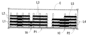
本実施例に係る長尺物用パレットP(以下、単にパレットとも記載する。)は、図1〜3に示すように、パレット本体1と、支柱連結体2a〜2eと、を備えて基本的には構成されている。
(1) Configuration of long object pallet A long object pallet P (hereinafter also simply referred to as a pallet) according to the present embodiment includes a
上記パレット本体1は、積載される長尺物Lの軸方向に沿って延びる鋼製角パイプ材よりなる複数の長尺基材3aと、積載される長尺物Lの並列方向に沿って延びる鋼製角パイプ材よりなる複数の長尺基材3bと、を格子状に枠組みして構成されている。そして、このパレット本体1は、40フィートのドライコンテナC(本発明に係る「輸送容器」として例示する。)の平面形状と略一致する平面矩形状をなしている。また、このパレット本体1には、複列複段(図3中では、5列4段)の長尺物Lが積載されるようになっている。なお、本実施例では、本発明に係る「長尺物」として鋼製の丸パイプ状物を例示する。
The pallet
上記パレット本体1の下面の左右側縁側には、鋼製角パイプ材よりなる複数の長尺基材4が設けられている。これら長尺基材4が床面に設置する脚部を構成している。また、パレット本体1の下面側には、下方及び積載される長尺物Lの軸方向を開放してなる下部開放空間Sが形成されている。
On the left and right edge sides of the lower surface of the
上記支柱連結体2a〜2eは、積載される長尺物Lの軸方向に沿ってパレット本体1に複数(図中5つ)配設されている。各支柱連結体2a〜2eは、図5に示すように、横断面コの字状の鋼材よりなされ上下方向に延びる左右一対の支柱5a,5bと、横断面コの字状の鋼材よりなされ横方向に延び且つ各支柱5a,5bの下端部を連結する連結部材6と、を有し、全体としてUの字状に形成されている。また、各支柱連結体2a〜2eでは、一対の支柱5a,5bが長尺物Lの並列方向に所定間隔で離間されている。上記連結部材6には長手方向に沿って複数の窓部6aが形成されている。また、この連結部材6の溝部6bには角材よりなる固定部材7が載置され、上記窓部6aを介して固定部材7とパレット本体1の長尺基材3aとが釘打ちされ、支柱連結体2a〜2eがパレット本体1に固定されている。
A plurality (five in the figure) of the
上記各支柱5a,5bには、図5及び6に示すように、その上方より挿入される後述の載置部材の両端部を上下方向に案内する案内溝8(本発明に係る「第1案内部」として例示する。)が設けられている。また、各支柱5a,5bには、その上方より挿入される後述の飛出し防止部材の切欠部を上下方向に案内する案内片9(本発明に係る「第2案内部」として例示する。)が設けられている。
As shown in FIGS. 5 and 6, each of the
上記一対の支柱5a,5bの間には、角材よりなる複数の載置部材10a〜10dの両端部が挿設されている。これら各載置部材10a〜10dの上には、複数の長尺物Lが並列状に載置されている。最下段用の載置部材10aは、上記固定部材7の上に載置されている。また、最上段用の飛出し防止部材13の両端部は、上記一対の支柱5a,5bの上部に形成された長孔11を介して各支柱5a,5bにネジ止めされている(図3参照)。また、最下段用及び最上段用以外の載置部材5b,5cは、下段側の長尺物Lの上に載置されている。
Between the pair of
上記載置部材5a〜5dの上には、角材よりなる横移動防止部材12(本発明に係る「横移動防止部」として例示する。)が載置され、釘打ちにより載置部材5a〜5d及び横移動防止部材12が固定されている。この横移動防止部材12は、積載された長尺物Lの周面に当接しており、長尺物の並列方向(横方向)への移動を防止する機能を発揮するようになっている。
On the
複数の支柱連結体2a〜2eのうちで積載される長尺物Lの両端部に対応する支柱連結体2a,2eにおいて、上記一対の支柱5a,5bの間には、横断面L字状の鋼材よりなる複数の飛出し防止部材13a〜13dの両端部が挿設されている。これら各飛出し防止部材13a〜13dは、各載置部材10a〜10dの上に載置されて、各載置部材10a〜10dに積載済みの長尺物Lの軸方向の端面に対向している(図4参照)。従って、各飛出し防止部材13a〜13dは、長尺物Lの軸方向への移動(飛出し)を防止する機能を発揮するようになっている。また、各飛出し防止部材13a〜13dの両端部には、図6に示すように、スリット状の切欠部14が形成されており、この切欠部14が上記支柱5a,5bの案内片9に挿入されて案内されるようになっている。
Among the plurality of
(2)長尺物用パレットへの長尺物の積載作用
次に、上記パレットPへの長尺物Lの積載作用について説明する。なお、パレット本体1には、積載予定の長尺物Lの軸方向の両端部及び中間部に対応して複数(図中5つ)の支柱連結体2a〜2eが予め固定されているものとする。
(2) Loading operation of a long object on the long object pallet Next, the loading operation of the long object L on the pallet P will be described. The
先ず、図7に示すように、各支柱連結体2a〜2eにおける左右一対の支柱5a,5bの案内溝8の間に、最下段用の載置部材10aの両端部を挿入して、この載置部材10aを、固定部材7の上に落とし込んで所定の高さ位置に位置決めする。
次に、図8に示すように、各支柱連結体2a〜2eの載置部材10aの上に複数の長尺物Lを並列させると共に、載置部材10aの上に横移動防止部材12を載置して釘打ちにより両部材を固定させる。各横移動防止部材12は、長尺物Lの周面に当接している。
次いで、図9に示すように、各支柱連結体2a,2eにおける一対の支柱5a,5bの案内片9の間に、上方より飛出し防止部材13の両端部の切欠部14を挿入して、この飛出し防止部材13を、載置部材10aの上に落とし込んで所定の高さ位置に位置決めする。このとき、飛出し防止部材13は、載置部材10aの上に載置済みの長尺物Lの軸方向の端面に対向している。
First, as shown in FIG. 7, both ends of the lowermost mounting
Next, as shown in FIG. 8, a plurality of long objects L are juxtaposed on the mounting
Next, as shown in FIG. 9, between the
その後、図10に示すように、各支柱連結体2a〜2eにおける一対の支柱5a,5bの案内溝8の間に、2段目用の載置部材10bの両端部を挿入して、この載置部材10bを、1段目の長尺物Lの上に落とし込んで所定の高さ位置に位置決めする。
次に、図11に示すように、各支柱連結体2a〜2eの載置部材10bの上に複数の長尺物Lを並列させると共に、載置部材10bの上に横移動防止部材12を載置して釘打ちにより両部材を固定させる。各横移動防止部材12は、長尺物Lの周面に当接している。
次いで、図12に示すように、各支柱連結体2a,2eにおける一対の支柱5a,5bの案内片9の間に、上方より飛出し防止部材13の両端部の切欠部14を挿入して、この飛出し防止部材13を、載置部材10bの上に落とし込んで所定の高さ位置に位置決めする。このとき、飛出し防止部材13は、載置部材10bの上に載置済みの長尺物Lの軸方向の端面に対向している。
Thereafter, as shown in FIG. 10, both end portions of the second-
Next, as shown in FIG. 11, a plurality of long objects L are juxtaposed on the mounting
Next, as shown in FIG. 12, the
その後、上述の作用(図10〜12)を2回繰り返し行って、パレットPには5列4段の長尺物Lが積載される。なお、最上段用の飛出し防止部材13は、各支柱5a,5bに長孔11を介してネジ止めされ所定の高さ位置に位置決めされている(図3参照)。その後、積載された長尺物L及びパレット本体1の外周側を固定バンド16で囲んで縛り上げて、一連の積載作業が終了されることとなる。
Thereafter, the above-described operation (FIGS. 10 to 12) is repeated twice, and the pallet P is loaded with the long objects L in five rows and four stages. In addition, the pop-up preventing
(3)昇降滑動装置の構成
本実施例に係る昇降滑動装置20は、図24及び25に示すように、所定位置に位置決めされるドライコンテナCの一端開口部Caに隣接するステージ21の床面上に設置される第1昇降滑動装置20aと、このステージ21及びドライコンテナCの床面上を変位可能な第2昇降滑動装置20bと、からなる。なお、上記ドライコンテナCは、トラック22のシャーシ23上に搭載されている。また、上記ステージ21は、そのドライコンテナCの床面の高さと実質的に同じ床面高さを有している。
(3) Configuration of Elevating / Sliding Device As shown in FIGS. 24 and 25, the elevating / sliding
上記第1昇降滑動装置20aは、図26〜28に示すように、床面上に接地する横断面Uの字状のベース部材24aを備えている。このベース部材24aの底面上には、繊維織物のジャケット体の内側にゴムをコーティングしてなるチューブ状の膨張部材25a(本発明に係る「第1昇降体」として例示する。)が敷設されている。この膨張部材25aの一端側には、空気供給源としてのエアコンプレッサ43が連結されている。また、ベース部材24aには、横断面Uの字状の支持部材26aが昇降自在に支持されている。この支持部材26aには、上記パレットPの下部開放空間Sを構成する底面を水平移動自在に支持する多数のローラ27a(本発明に係る「第1滑動体」として例示する。)が回転自在に支持されている。従って、膨張部材25aの膨縮によって、支持部材26aと共に多数のローラ27aが昇降され、これらローラ27aに支持された上記パレットPを床面に対して浮上させたり(図29参照)、接地させたり(図30参照)するようになっている。
尚、上記第2昇降滑動装置20bは、第1昇降滑動装置20aと略同じ構成であり、同じ構成部位の符号の最後には一方に「a」を他方に「b」を付けてある。
As shown in FIGS. 26 to 28, the first elevating / sliding
The second elevating / sliding
上記ステージ21には、図25に示すように、上記第1又は第2昇降滑動装置20a,20bにより支持され床面より浮上された記パレットPをステージ21とドライコンテナCとの間で水平移動させる一対二組のプッシュ・プル機構28a,28b,29a,29bが設けられている。これらのプッシュ・プル機構28a,28b,29a,29bは、上記第2昇降滑動装置20bをステージ21とドライコンテナCとの間で水平移動させ得る機能も有している。
On the
(4)ドライコンテナへの長尺物の搬入作用
次に、上記第1及び第2昇降滑動装置20a,20bを用いた40フィートのドライコンテナCへの長尺物Lの搬入作用について説明する。
先ず、搬入作用の準備作業として、ステージ21の床面上には、第1昇降滑動装置20a、第2昇降滑動装置20b及びプッシュ・プル機構28a,28b,29a,29bが用意されている。このとき、第1及び第2昇降滑動装置20a,20bにおいて、膨張部材25a,25bは収縮されており多数のローラ27a,27bが降下した状態である。
(4) Loading Operation of Long Object into Dry Container Next, the operation of loading the long object L into the 40-foot dry container C using the first and second elevating / sliding
First, as preparatory work for the carrying-in action, a first elevating / sliding
次に、トラック22の移動によって、このトラック22のシャーシ23上に搭載されたドライコンテナCを、その一端開口部Caがステージ21の先端部に近接する所定位置に位置させる。このとき、ステージ21の床面とドライコンテナCの床面との高さレベルが略一致している。
次いで、プッシュ・プル機構28a,28b,29a,29bによって、ステージ21上の第2昇降滑動装置20bを、ドライコンテナC側に押し込んでドライコンテナCの床面上に位置させる。
その後、クレーン、フォークリフト等の荷役手段によって、ステージ21上の第1昇降滑動装置20aの上に長尺物積載パレットPが用意される。このとき、パレットPはステージ21の床面上に接地されていると共に、パレットPの下部開放空間S内に第1昇降滑動装置20aが収納されている。
Next, the movement of the
Next, the second elevating / sliding
Thereafter, the long object loading pallet P is prepared on the first lifting / lowering sliding
次に、第1及び第2昇降滑動装置20a,20bにおいて、エアコンプレッサ43の作用で膨張部材25a,25bにエアを供給して、この膨張部材25a,25bを膨張させる。すると、支持部材26a,26bと共に多数のローラ27a,27bが上昇される。このとき、第1昇降滑動装置20aによって、パレットPがステージ21の床面上から持ち上げられる。
次いで、プッシュ・プル機構28a,28b,29a,29bによって、浮上状態のパレットPがドライコンテナC側に向かって押し込まれる。すると、水平移動されるパレットPは、第1昇降滑動装置20aから第2昇降滑動装置20bに受け渡される。
その後、第1及び第2昇降滑動装置20a,20bにおいて、膨張部材25a,25bへのエアの供給を停止して、膨張部材25a,25bからエアを排気して収縮させる。すると、支持部材26a,26bと共に多数のローラ27a,27bが下降される。このとき、第2昇降滑動装置20bによって、パレットPがドライコンテナCの床面上に接地される。
次に、プッシュ・プル機構28a,28b,29a,29bによって、第2昇降滑動装置20bを、ステージ21側に向かって引き込んでステージ21の床面上に位置させて、一連のドライコンテナCへの長尺物Lの搬入作用が終了されることとなる。
Next, in the first and second elevating / sliding
Next, the pallet P in the floating state is pushed toward the dry container C side by the push /
Thereafter, in the first and second elevating / sliding
Next, the second elevating / sliding
なお、上記実施例では、第1及び第2昇降滑動装置20a,20bを用いたドライコンテナCへの長尺物積載パレットPの搬入作用について説明したが、第1及び第2昇降滑動装置20a,20bを用いてドライコンテナCから長尺物積載パレットPを搬出することもできる。
即ち、長尺物積載パレットPを収容したドライコンテナCを、その一端開口部Caがステージ21の先端部に近接する所定位置に位置させる。次に、ステージ21上の第2昇降滑動装置20bを、ドライコンテナC側に押し込んでドライコンテナCの床面上に位置させる。このとき、パレットPの下部開放空間S内に第2昇降滑動装置20bが収納されている。その後、第1及び第2昇降滑動装置20a,20bにおいて、この膨張部材25a,25bを膨張させて多数のローラ27a,27bを上昇させる。すると、第2昇降滑動装置20bによって、パレットPがドライコンテナCの床面上から浮上される。次いで、浮上状態のパレットPがステージ21側に向かって引き込まれ、水平移動されるパレットPは、第2昇降滑動装置20bから第1昇降滑動装置20aに受け渡され、ステージ21上に搬出される。その後、ドライコンテナC内の第2昇降滑動装置20bを、ステージ21側に引き込んでステージ21上に位置させ、一連の搬出作用が終了されることとなる。
In addition, although the said Example demonstrated the carrying-in effect | action of the elongate article loading pallet P to the dry container C using the 1st and 2nd raising / lowering sliding
That is, the dry container C containing the long object loading pallet P is positioned at a predetermined position where the one end opening portion Ca is close to the front end portion of the
(5)搬送台車の構成
本実施例に係る搬送台車30は、図31〜33に示すように、パレットPの下部開放空間S内に進入可能な大きさ・サイズに形成されている。この搬送台車30は、所定の間隔でもって並設される左右一対の昇降ユニット31a,31bを備えている。各昇降ユニット31a,31bは、図34及び35に示すように、搬送方向に沿って延びる横断面Uの字状のベース部材32を有している。このベース部材32の内部には、その長手方向に沿って所定間隔でもって多数の回転ローラ33が水平軸回りに回転自在に支持されている。また、このベース部材32には、搬送方向に沿って延びる横断面U字状のパレット支持部材35が昇降自在に支持されている。このパレット支持部材35の上面によって、パレットPの下部開放空間Sを構成する底面が下方より載置支持される。また、両昇降ユニット31a,31bの各パレット支持部材35の長手方向の一端側は板状の連結部材36によって連結され、両昇降ユニット31a,31bは一体物とされている。この連結部材36の外面側には、左右一対の当接部37が設けられ、各当接部37には、その流路を切り換えるための流体排出用バルブとしての当接バルブ38が取着されている。
(5) Configuration of Conveying Cart The conveying
また、上記ベース部材32とパレット支持部材35との間には、繊維織物のジャケット体の内側にゴムをコーティングしてなり且つ圧縮空気の給排により膨縮するチューブ状の膨縮部材39が配設されている。この膨縮部材39の一端開口部には、図36に示すように、圧縮空気を通気するための可撓性の配管40が接続されている。この配管40の他端側はジョイント具41及びエアホース42を介して空気供給源としてのエアコンプレッサ43に連結されている。また、この配管40の途中には、パイロット型の第1バルブ44、第2バルブ45、第3バルブ46、押釦バルブ47及び上記当接バルブ38が設けられ、これらのバルブ44,45,46,47,38によって開閉バルブ機構50が構成されている。そして、押釦バルブ47を押圧操作すると、エアコンプレッサ43からの圧縮空気が膨縮部材39に供給されて膨縮部材39が膨張し、パレット支持部材35が上昇されるようになっている。また、パレット支持部材35の上昇状態より、当接バルブ38が当接操作されてその流路が切り換えられると、膨縮部材39に供給された圧縮空気が外部に排出されて膨縮部材39が収縮し、パレット支持部材35が下降されるようになっている。
Between the
(6)ドライコンテナからの長尺物の搬出作用
次に、上記搬送台車30を用いた40フィートのドライコンテナCからの長尺物Lの搬出作用について説明する。
先ず、搬出作用の準備作業として、ステージ21の床面上には、搬送台車30及びウインチWが用意されている。このとき、搬送台車30において、膨縮部材39は収縮されておりパレット支持部材35が降下した状態である。
(6) Unloading action of long object from dry container Next, the unloading action of the long object L from the 40-foot dry container C using the
First, as a preparatory work for the unloading action, a
次に、トラック22の移動により、このトラック22のシャーシ23上に搭載されたドライコンテナCを、その一端開口部Caがステージ21の先端部に近接する所定位置に位置させる。このとき、ステージ21の床面とドライコンテナCの床面との高さレベルが略一致している。また、ドライコンテナC内には、長尺物積載パレットPが収容されている。次いで、人手によりステージ21上の搬送台車30がドライコンテナC側に押し込まれる(図37参照)。すると、搬送台車30は、ドライコンテナC内にあるパレットPの下部開放空間S内に収納される。その状態より、押釦バルブ47を押圧操作すると、膨縮部材39に圧縮空気が供給されて膨縮部材39が膨張し、パレット支持部材35が上昇され、このパレット支持部材35によってパレットPがドライコンテナCの床面上から持ち上げられる。
Next, the movement of the
その後、搬送台車30に連結されたワイヤロープ53をウインチWで巻上げると、搬送台車30と共にパレットPがステージ21側に向かって引っ張られる(図38参照)。そして、その搬送台車30の走行中に、当接バルブ38がステージ21の床面上に設けたストッパ部材51に当接すると、膨縮部材39に供給された圧縮空気が外部に排気されて膨縮部材39が収縮し、パレット支持部材35が降下され、このパレット支持部材35に支持されたパレットPがステージ21の床面上に載置される。
次に、クレーン等によって、このステージ21上に搬出されたパレットPが所望の位置まで移送され、一連の長尺物の搬出作用が終了されることとなる。
Thereafter, when the
Next, the pallet P unloaded onto the
なお、上記実施例では、搬送台車30を用いたドライコンテナCからの長尺物積載パレットPの搬出作用について説明したが、搬送台車30を用いてドライコンテナCへ長尺物積載パレットPを搬入することもできる。
即ち、空のドライコンテナCを、その一端開口部Caがステージ21の先端部に近接する所定位置に位置させ、ステージ21上において、パレット支持部材35によりパレットPを持ち上げた状態の搬送台車30を、ドライコンテナC側に押し込んでドライコンテナCの床面上に位置させる。その後、搬送台車30の膨縮部材39を収縮させてパレット支持部材35を降下させ、パレットPをドライコンテナCの床面上に接地させる。この状態より、パレットPの下部開放空間S内に収納された搬送台車30をステージ21側に引き戻して、一連の搬出作用が終了されることとなる。
In the above embodiment, the operation of carrying out the long object loading pallet P from the dry container C using the conveying
In other words, the empty dry container C is positioned at a predetermined position where the one end opening Ca is close to the tip of the
(7)他の搬送台車、案内具及びステージの構成
本実施例に係る搬送台車30’は、上記搬送台車30と略同じ構成を有しており、搬送台車30と同じ構成部位には符号の後に「’」を付け詳説は省略する。
上記搬送台車30’は、図39に示すように、40フィートのドライコンテナCの全長に相当する長尺状の左右一対の昇降ユニット31a’,31b’を備えている。各昇降ユニット31a’,31b’は、図40及び41に示すように、複数の回転ローラ33’を回転自在に支持するベース部材32’と、このベース部材32’に昇降自在に支持されるパレット支持部材35’と、ベース部材32’とパレット支持部材35’との間に配設される膨縮部材39’と、を備えている。
上記パレット支持部材35’の左右の側面側には、図40及び41に示すように、その長手方向に所定間隔でもって複数の案内ローラ60(本発明に係る「被案内部」として例示する。)が垂直軸回りに回転自在に支持されている。
(7) Configurations of other transport carts, guides, and stages The
As shown in FIG. 39, the
As shown in FIGS. 40 and 41, the left and right side surfaces of the
本実施例に係る案内具61a,61bは、図39に示すように、各昇降ユニット31a’,31b’に対応して一対設けられている。各案内具61a,61bは、図40及び41に示すように、横断面Uの字状の案内本体62を備えている。この案内本体62は、上記搬送台車30’が走行可能である平板状の床部62a(本発明に係る「走行部」として例示する。)と、この床部62aの左右の側縁から上方に立ち上がり且つ上記搬送台車30’に設けられた案内ローラ60を案内する左右の垂直壁部62b(本発明に係る「案内部」として例示する。)と、各垂直壁部62bの上端縁から外側方に水平に伸びる左右の水平壁部62cと、からなっている。
As shown in FIG. 39, a pair of
上記各水平壁部62cの下面側には、搬送方向に所定間隔でもって複数の走行機構63が設けられている。この走行機構63は、各水平壁部62cの下面側に取着されるベース部材64を有している。このベース部材64には、支持部材65が昇降自在に支持されている。この支持部材65には、床面上を走行する複数の走行ローラ66が水平軸回りに回転自在に支持されている。また、上記支持部材65とベース部材64との間には、繊維織物のジャケット体の内側にゴムをコーティングしてなり且つ圧縮空気の給排により膨縮するチューブ状の膨縮部材67が介在されている。そして、この膨縮部材67の収縮により案内本体62が床面に接地(図40参照)すると共に、膨縮部材67の膨張により案内本体62が床面から浮上(図41参照)するようになっている。
A plurality of
なお、上記案内具61a,61bの先端側には、蛇行防止バー68(図43参照)が着脱自在に装着され得るようになっている。この蛇行防止バー68の両端部には、ドライコンテナCの内壁面に案内される案内ローラ68aが回転自在に支持されている。また、上記案内具61a,61bの後端側には、エア駆動される周知の荷役手段69(図43参照)が着脱自在に装着され得るようになっている。この荷役手段69は、作業者による搬送作業を補助するものである。
A meandering prevention bar 68 (see FIG. 43) can be detachably attached to the distal end sides of the
本実施例に係るステージ70aの長手方向の一端側には、図42に示すように、ドライコンテナCが載置される枠状のコンテナ架台70bが設けられている。このステージ70aとコンテナ架台70bに載置されるドライコンテナCとは、それぞれの床面の高さレベルが実質的に同じとなっている。上記コンテナ架台70bの四隅部には、ドライコンテナCに既設された隅金具の孔部が挿入される挿入ピン(図示せず)が設けられている。また、ステージ70aの側縁部には、フォークリフト等が乗り上がることができる踏み台71が着脱自在に固定されている。また、ステージ70aの側縁部には、その床面より上方に突出し且つ長尺物積載パレットの側面が当接する一対の位置決め部72が設けられている。さらに、ステージ70aの後端部には、ワイヤロープを巻き取り出し可能なウインチ73(図48参照)が設置される。
As shown in FIG. 42, a frame-shaped
(8)ドライコンテナへの長尺物の搬入作用
次に、上記搬送台車30’、案内具61a,61b及びステージ70aを用いた40フィートのドライコンテナCへの長尺物Lの搬入作用について説明する。
先ず、図39に示すように、クレーン、フォークリフト等によって、一端開口部を開口させた状態のドライコンテナCをコンテナ架台70bに載せる。このとき、ドライコンテナCの隅金具の孔部が挿入ピンに挿入されている。次に、ドライコンテナC及びステージ70aの床面の高さレベルを測定し、レベル調整が必要な場合には、ジャッキ等によりドライコンテナCを持ち上げてシム調整等を行う。
(8) Loading operation of long object into dry container Next, the operation of transferring long object L into the 40-foot dry container C using the transport carriage 30 ', guides 61a and 61b and the
First, as shown in FIG. 39, a dry container C with one end opening portion opened is placed on the
次いで、図43に示すように、ステージ70aの床面上に、各昇降ユニット31a’,31b’を搭載した状態の一対の案内具61a,61bを載せる。このとき、昇降ユニット31a’,31b’及び案内具61a,61bを、適宜固定手段(例えば、固定ピン等)により固定させておく。その後、各案内具61a,61bの先端側に蛇行防止ガイド68を装着する。次に、各案内具61a,61bにおいて、膨縮部材67にエアを供給してこの膨縮部材67を膨張させ、案内本体62をステージ70aの床面上から浮上させる。この浮上状態で、各案内具61a,61bの後端側に荷役手段69を連結して、作業者が荷役手段69を操作して、各案内具61a,61bを、ドライコンテナC側に向って押し込んでステージ70a及びドライコンテナCの床面上を走行させる。このとき、蛇行防止ガイド68の案内ローラ68aが、ドライコンテナCの内壁面に案内され、各案内具61a,61bは良好な直進性を保って移送されることとなる。また、各昇降ユニット31a’,31b’の上には、ゴム製のスペーサ部材が置かれている。なお、このスペーサ部材の替わりに機械的に昇降可能な昇降具(例えば、ジャッキ等)を用いてもよい。
Next, as shown in FIG. 43, on the floor surface of the
その後、図44に示すように、各案内具61a,61bがドライコンテナC内に収容されると、各案内具61a,61bから荷役手段69を取り外すと共に、膨縮部材67からエアを排気してこの膨縮部材67を収縮させ、案内本体62をドライコンテナCの床面上に載置させる。次に、昇降ユニット31a’,31b’及び案内具61a,61bの固定を解除して、各案内具61a,61bから蛇行防止ガイド68を取り外す。次いで、クレーン、フォークリフト等によって、長尺物積載パレットPをステージ70aの床面上に載せる。このとき、長尺物積載パレットPの側面を一対の位置決め部72に当接させることによって、長尺物積載パレットPが搬入方向に真直ぐに向けられることとなる。その後、位置決め部72を、長尺物積載パレットと接触しない退避位置に位置させる。
Thereafter, as shown in FIG. 44, when the
次いで、各昇降ユニット31a’,31b’を、各案内具61a,61bからステージ70a側に向って引っ張り出す。すると、各昇降ユニット31a’,31b’が、案内本体62の床部62a及びステージ70aの床面上を走行され、図45に示すように、長尺物積載パレットPの下部開放空間内Sに進入する。この状態より、各昇降ユニット31a’,31b’において、膨出部材39’にエアを供給して膨縮部材39’を膨張させると、パレット支持部材35’と共に長尺物積載パレットPがステージ70aの床面上から持ち上げられる。その後、長尺物積載パレットPに荷役手段69を装着し、作業者が荷役手段69を操作して、昇降ユニット31a’,31b’を、ドライコンテナC側に向って押し込んでステージ70a及び案内本体62の床部62aの床面上を走行させる。このとき、図46に示すように、各昇降ユニット31a’,31b’の案内ローラ60が案内本体62の垂直壁部62bに案内され、各昇降ユニット31a’,31b’と共に長尺物積載パレットPは、良好な直進性を保って移送されることとなる。
Next, the elevating
次に、図47に示すように、各昇降ユニット31a’,31b’と共に長尺物積載パレットPがドライコンテナC内に収容されたら、荷役手段69を取り外す。次いで、各昇降ユニット31a’,31b’において、膨縮部材39’からエアを排気してこの膨縮部材39’を収縮させ、パレット支持部材35’と共に長尺物積載パレットPを下降させ、この長尺物積載パレットPをドライコンテナCの床面上に載置させる。その後、スペーサ部材を取り外してから、各昇降ユニット31a’,31b’と各案内具61a,61bとを適宜固定手段(固定ピン等)で固定し、各昇降ユニット31a’,31b’にウインチ73から引き出したワイヤロープ78を連結する。次に、各案内具61a,61bにおいて、膨縮部材67にエアを供給してこの膨縮部材67を膨張させて、案内本体62をドライコンテナCの床面から浮上させる。この状態より、ウインチ73によりワイヤロープ78を巻き取ると、各昇降ユニット31a’,31b’を搭載した状態の各案内具61a,61bが、ドライコンテナC及びステージ70aの床面上を走行して、ステージ70aの床面上に位置され(図48参照)、一連の搬入作業が終了されることとなる。
Next, as shown in FIG. 47, when the long object loading pallet P is accommodated in the dry container C together with the elevating
(7)実施例の効果
本実施例の長尺物用パレットPによると、一対の支柱5a,5bの案内溝8の間に、載置部材10a〜10dの両端部を挿入して、この載置部材10a〜10dを積載済みの長尺物Lの上に載置し、一対の支柱5a,5bの案内片9の間に、飛出し防止部材13a〜13dの両端部の切欠部14を挿入して、この飛出し防止部材13a〜13dを挿設済みの載置部材10b〜10dの上に載置し、上記載置部材10a〜10dの上には長尺物Lが並列状に載置され、上記飛出し防止部材13a〜13dが、その並列状の長尺物Lの軸方向の端面に対向するようにしたので、ドライコンテナの輸送時、パレットの搬送時等に、飛出し防止部材13a〜13dによって、パレットPに積載された長尺物Lの軸方向への飛び出しが防止される。また、上下に段積みされる長尺物Lは載置部材10a〜10dにより仕切られて互いに直接的に接触しないので、パレットPへの長尺物Lの積載時、ドライコンテナの輸送時、パレットの搬送時等に長尺物L同士の衝突や摩擦接触等により長尺物を損傷させてしまうことを抑制できる。また、飛出し防止部材13a〜13dが載置部材10a〜10dの上に載置されているので、この載置部材10a〜10dの上に載置される長尺物Lの外径に拘わらず、飛出し防止部材13a〜13dによって、パレットPに積載された長尺物Lの軸方向への飛出しを防止することができる。また、載置部材10a〜10d及び飛出し防止部材13a〜13dを、一対の支柱5a,5bの間に挿入して落とし込むだけで所定の高さ位置にセットできるので、長尺材Lの積載作業をさらに迅速且つ簡易に行うことができる。さらに、固定バンド16等によるラッシング作業を必要最小限とすることができる。以上より、様々な種類、形状の長尺物を損傷させることなく安定的に且つ輸送費用を抑えて輸送することができる長尺物用パレット及びそのパレットへの長尺物の積載方法を提供することができる。
また、本実施例の長尺物用パレットPでは、載置部材10a〜10dが角材よりなされ、飛出し防止部材13a〜13dが横断面L字状の鋼材よりなされ、支柱5a,5bが横断面コの字状の鋼材よりなされているので、載置部材10a〜10dが緩衝機能を発揮して長尺材Lの損傷等をより確実に抑制できると共に、飛出し防止部材13a〜13d及び支柱5a,5bによってパレットP全体の剛性を向上させることができる。その結果、長尺物積載パレットをクレーンにより安全に吊り下げ搬送したり、フォークリフトで持ち上げ搬送したりすることができる。
また、本実施例の長尺物用パレットPでは、最上段用の飛出し防止部材13の両端部が一対の支柱5a,5bに固定手段(ネジ止め等)により固定されているので、さらにパレットの剛性を向上させることができる。
また、本実施例の長尺物用パレットPでは、載置部材10a〜10dの上に横移動防止部材12を設けるようにしたので、この載置部材10a〜10dに載置された長尺物Lの横方向への移動をより確実に防止することができる。
(7) Effects of Example According to the long object pallet P of this example, both ends of the mounting
Moreover, in the pallet P for elongate objects of a present Example, the mounting
Further, in the long object pallet P of the present embodiment, both ends of the uppermost pop-out preventing
Further, in the long object pallet P of the present embodiment, since the lateral
本実施例のドライコンテナCへの長尺物Lの搬送方法によると、40フィートのドライコンテナCに対して一度に大量の長尺物Lを良好な直進性を保って搬送することができる。また、ドライコンテナCに対してモジュール化されたパレットPを使用しているので、ドライコンテナC内に無駄な隙間なく長尺物Lを積載することができる。また、ドライコンテナC内で長尺物Lの煩雑な固定作業を必要最小限(実質零)に抑えることができ、長尺物Lの搬送作業をより効率化することができる。さらに、ステージ21上、ステージ21の周囲等に、ドライコンテナCへ搬入予定の長尺物L、長尺物積載パレットPを予め準備しておくことができるので、やはり長尺物の搬送作業を効率化することができる。
なお、上記搬送方法で使用される昇降滑動装置20は、例えば、大量の貨物を頻繁に取り扱う物流センター、C・F・S(コンテナ・フレート・ステーション)等で好適に用いられることができる。また、上記搬送方法で使用される搬送台車30は、上記昇降滑動装置20に比べて安価且つ簡易な構造であり、大量の貨物を頻繁に取り扱う必要のない貨物の受け手側等で好適に用いられることができる。
According to the method for transporting the long object L to the dry container C of the present embodiment, a large amount of the long object L can be transported to the 40-foot dry container C at a time while maintaining good straightness. Moreover, since the modularized pallet P is used for the dry container C, the long object L can be loaded in the dry container C without a useless gap. Moreover, the complicated fixing operation | work of the long object L in the dry container C can be suppressed to required minimum (substantially zero), and the conveyance operation | work of the long object L can be made more efficient. Furthermore, since the long object L and the long object loading pallet P to be carried into the dry container C can be prepared in advance on the
The elevating / sliding
(8)その他のステージの構成
次に、上記搬送台車30’を用いた長尺物積載パレットPの搬入作業において好適に使用される他のステージ80の構成について説明する。なお、このステージ80は、上述のステージ70aと略同じ構成であり、同じ構成部位には同じ符号を付けて詳説を省略する。
(8) Configuration of Other Stages Next, the configuration of another
上記ステージ80は、図54及び55に示すように、ステージ本体81aと、このステージ本体81aの下面側に設けられる脚部81bと、を有している。このステージ本体81aの平面形状は、40フィートのドライコンテナCの平面形状と対応した大きさに設定されている。また、上記脚部81bは、ステージ本体81aの左右側縁に沿って複数対(図中5対)設けられている。また、各脚部81bの下部には、ステージ本体81aの床面高さを調整可能な高さ調整機構82が設けられている。この高さ調整機構82は、図58に示すように、上下に対向する固定板83を複数のネジ軸84でネジ止めし、これら固定板83の間に複数のシム85を介在して構成されている。下側の固定材83の下面には、二トリルゴムからなり且つ固定材と略同じ平面形状を有する免振ゴム部材86が設けられている。
As shown in FIGS. 54 and 55, the
上記ステージ80の側縁部には、踏み台71が着脱自在に設けられている。また、ステージ本体81aの側縁部には、複数の位置決め部材72が設けられている。各位置決め部材72は、支持ピン87を介して水平軸回りに回転自在に支持されている。そして、各位置決め部材72は、ステージ80上に載せられる長尺物積載パレットPに当接し得る作用位置(図55中実線で示す)と、ステージ80上に載せられた長尺物積載パレットPに当接しない退避位置(図55中仮想線で示す)との間で変位自在とされ、くさび(図示せず)で各位置に位置決めされるようになっている。さらに、ステージ80の後端部には一対のウインチ73が設置される。
A
上記ステージ80の前端側には、ドライコンテナCが載置されるコンテナ架台88が連絡されている。このコンテナ架台88は、枠状の架台本体89aと、この架台本体89aの下面側に設けられる脚部89bと、を有している。この架台本体89aの4隅部には、ドライコンテナCの底側4隅部の隅金具に形成された孔部(図示せず)に挿入し得る複数の凸部90(図57及び58参照)が設けられている。また、この架台本体89aの長手方向の中央部上面側には、図56に示すように、上方及び左右方向(ドライコンテナの横幅方向)が開放された上部切欠部91が形成されている。この上部切欠部91は、フォークリフトのフォーク部fが左右方向から挿脱し得る大きさに設定されている。また、上記コンテナ架台88には上部切欠部91に対応する位置に、上部切欠部91に挿入されるフォークリフトのフォーク部fを水平に案内するフォーク部案内板92が設けられている。また、上記コンテナ架台88の脚部89bは、架台本体89aの左右側縁に沿って複数対(図中3対)設けられている。また、各脚部89bの下部には、架台本体89aの床面高さを調整可能であり且つ上記高さ調整機構82と同じ構成である高さ調整機構93が設けられている(図58参照)。
尚、本実施例では、上記凸部90が架台本体89aの4隅部に設けられ、40フィートのドライコンテナCを位置決め支持するようにしたが、これに限定されず、架台本体89aの長手方向の中央部にも凸部を設け、1台のコンテナ架台88で40フィート及び20フィートのドライコンテナを位置決め支持し得るようにしてもよい。
A
In the present embodiment, the
上記ステージ80及びコンテナ架台88の連絡部には、図57及び58に示すように、ステージ80及びコンテナ架台88の前後方向(連絡方向)及び左右方向(横幅方向)を位置決めする前後方向及び左右方向の位置決め手段95,96が設けられている。上記前後方向の位置決め手段95は、ステージ80の前端側に設けられる被噛合部95aと、コンテナ架台88の後端側に設けられ且つ被噛合部95aに上下方向から噛合う噛合部95bと、を有している。また、上記左右方向の位置決め手段96は、ステージ80の前端側に設けられる左右一対の被係合部96aと、コンテナ架台88の後端側に設けられ且つ一対の被係合部96aの間に上下方向から係合する左右一対の係合部96bと、を有している。さらに、上記ステージ80及びコンテナ架台88の連絡部には、上述の案内具61a,61bの移動(走行)を案内する複数(図中4つ)の移動案内ローラ98が垂直軸回りに回転自在に支持されている。各移動案内ローラ98は、移動中の案内具61a,61bの案内本体62を構成する垂直壁部62bの外側面を案内するようになっている。
As shown in FIGS. 57 and 58, the connecting portion of the
(9)その他のステージの作用・効果
次に、上記ステージ80及びコンテナ架台88の設置作用について説明する。
先ず、クレーン、フォークリフト等によりステージ80を設置場所へ移動する。このとき、ステージ80の上には、上記昇降ユニット31a’,31b’を収納した状態の案内具61a,61bが適宜固定手段(例えば、固定ピン等)により固定されている。次に、ステージ80の各脚部81bにおいて、高さ調整機構82に適量のシム85をセットする。なお、シム量は、事前に床レベル調整し設定される。次いで、ステージ80を設置場所(マーキング箇所)へ降ろす。
(9) Operation and Effect of Other Stages Next, the installation operation of the
First, the
その後、クレーン、フォークリフト等によりコンテナ架台88を移動する。次に、コンテナ架台88の各脚部89bにおいて、高さ調整機構93に適量のシム85をセットする。なお、シム量は、事前に床レベル調整し設定される。次いで、コンテナ架台88をステージ80付近まで移動させ、ステージ80の前端部とコンテナ架台88の後端部とを位置合せし、コンテナ架台88を降ろす。このとき、コンテナ架台88の係合部96bがステージ80の被係合部96aに上方から係合されると共に、コンテナ架台88の噛合部95bがステージ80の被噛合部95aに上方から噛合わされ、ステージ80及びコンテナ架台88は、前後方向及び左右方向に位置決め固定された状態となる。その後、ステージ80に踏み台71が固定セットされる。
Thereafter, the
次に、上述のステージ70を用いた搬入作用と略同じ手順で搬入が行われることとなる。なお、フォークリフトを用いてコンテナ架台88に対してドライコンテナCを移送する場合、ドライコンテナCがコンテナ架台88に載せられた後、フォークリフトのフォーク部fは、上部切欠部91から抜き出される一方、フォークリフトのフォーク部fを上部切欠部91に挿入させた後、このフォーク部fでドライコンテナCを下方より持ち上げてコンテナ架台88から移送される(図54及び56参照)。そして、フォークリフトのフォーク部fが上部切欠部91を挿通する際、フォーク部fの先端側はフォーク部案内板92により水平に案内される。
Next, the carry-in is performed in substantially the same procedure as the carry-in action using the stage 70 described above. When the dry container C is transferred to the
以上より、上記実施例では、ステージ80及びコンテナ架台88の連絡部に、前後方向及び左右方向の位置決め手段95,96を設けたので、ステージ80の前端側に、前後方向及び左右方向を位置決めされた状態でコンテナ架台88を連結することができる。また、本実施例では、ステージ80の脚部81b及びコンテナ架台88の脚部89bのそれぞれに高さ調整機構82,93を設けたので、ステージ80及びコンテナ架台88に良好な水平度を与えて、ステージ80の床面の高さレベルと、コンテナ架台88に載置されるドライコンテナCの床面の高さレベルとをより確実に一致させることができる。また、本実施例では、ステージ80に、作用位置と退避位置とに変位し得るように位置決め部材72を設けたので、長尺物積載パレットPをステージ80上に載せる際、長尺物積載パレットPを、作用位置の位置決め部材72に当接させて搬送方向に沿って真直ぐに向けることができる。また、位置決め部材72を退避位置に位置させれば、長尺物積載パレットPを、位置決め部材72に接触させることなく搬送台車30’で真直ぐに移送させることができる。さらに、本実施例では、上記ステージ80及びコンテナ架台88の連絡部に、案内具61a,61bの移動(走行)を案内する移動案内ローラ98を垂直軸回りに回転自在に設けたので、搬送台車30’を収納した状態の案内具61a,61bを真直ぐに移動させることができる。
以上の結果、昇降量を必要最小限とした安価且つ小型な構造の搬送台車30’を用いて、40フィートのドライコンテナCに対して長尺物積載パレットPを良好な直進性を保って一度に搬入することができる。
As described above, in the above embodiment, the front and rear direction and left and right direction positioning means 95 and 96 are provided in the connecting portion of the
As a result of the above, using a low-priced and small-
また、本実施例では、ステージ80及びコンテナ架台88の脚部81b,89bの接地面に免振ゴム部材86を設けたので、アンカーボルトを用いずにステージ80及びコンテナ架台88を設置しても、その設置床面に対する摩擦力の向上に加えて免振効果によってステージ80及びコンテナ架台88の位置ズレを抑制することができる。また、本実施例では、ステージ80の側縁部にフォークリフト等が乗り上げ可能な踏み台71を設けたので、この踏み台71上に乗り上げられたフォークリフト等の荷重がステージ80及びコンテナ架台88にかかり、ステージ80及びコンテナ架台88の位置ズレ等をより確実に抑制することができる。
また、本実施例では、架台本体89aの上面側に上部切欠部91を設けたので、フォークリフトのフォーク部fを上部切欠部91に左右方向から挿脱でき、フォークリフト等の持ち上げ式の荷役手段を用いて、架台本体89aに対してドライコンテナCを載置したり移動したりすることができる。また、本実施例では、架台本体89aの上面側には上部切欠部91に対応する位置にフォーク部案内板92を設けたので、上部切欠部91に対してフォークリフトのフォーク部f等をより円滑に挿脱させることができる。しかも、架台本体89aの強度を向上させることもできる。
Further, in this embodiment, since the vibration isolating
Further, in this embodiment, since the
尚、本発明においては、上記実施例に限られず、目的、用途に応じて本発明の範囲内で種々変更した実施例とすることができる。即ち、上記実施例では、パレットPに積載される長尺物Lとして、その軸方向長さが同じものを例示したが、これに限定されず、例えば、図13に示すように、1つのパレットPに軸方向長さの異なる第1長尺部L1及び第2長尺物L2を混載することができる。この場合、支柱連結体としては、第1長尺物L1の軸方向の少なくとも両端部に対応して設けられる二組の第1支柱連結体2a,2e(本発明に係る「第1支柱」として例示する。)と、第2長尺物L2の軸方向の少なくとも両端部に対応して設けられる二組の第2支柱連結体2b,2d(本発明に係る「第2支柱」として例示する。)と、を備え、第1支柱連結体2a,2e及び第2支柱連結体2b,2dの各支柱5a,5bの間に、飛出し防止部材13a〜13dが挿設されている。また、第1支柱連結体2a,2e及び第2支柱連結体2b,2dのそれぞれの二組が、パレット本体1の前後方向の中心から前後対称に配設されている。これにより、軸方向長さの異なる第1長尺物L1及び第2長尺物L2を、パレット本体1の中央部にバランス良く積載することができ、輸送時、搬送等の荷崩れを抑制することができる。さらに、第1及び第2長尺物L1,L2に加えて、更に異なる軸方向長さの長尺物を混載する場合には、その長尺物の軸方向の両端部にも対応して支柱連結体を設ければこれに対応することができる。
In the present invention, the present invention is not limited to the above embodiment, and various modifications can be made within the scope of the present invention depending on the purpose and application. That is, in the said Example, although the thing with the same axial direction length was illustrated as the elongate object L loaded on the pallet P, it is not limited to this, For example, as shown in FIG. The 1st elongate part L1 and the 2nd elongate object L2 from which axial direction length differs can be mixedly mounted in P. FIG. In this case, as the support columns, two sets of
また、上記実施例では、パレットPに積載される長尺物Lとして、その横断面形状(外径等)が同じものを例示したが、これに限定されず、例えば、図14に示すように、横断面丸環状の大径の長尺物La、多数の棒材を束ねてなる長尺物Lb、横断面四角環状の長尺物Lc、横断面丸環状の小径の長尺物Ld等を混載することができる。なお、長尺物Lbに対応する飛出し防止部材13bは、その長尺物Lbの端面を覆い得る平板状に形成されていることが好ましい。さらに、パレットPに積載される長尺物としては、例えば、その軸方向の端部が曲折しているL字状の長尺物Le(図15参照)、その軸方向に沿って湾曲するL字状の長尺物Lf(図16参照)等を挙げることができる。
Moreover, in the said Example, although the thing with the same cross-sectional shape (outside diameter etc.) was illustrated as the elongate object L loaded on the pallet P, it is not limited to this, For example, as shown in FIG. A large-diameter long object La having a circular cross section, a long object Lb formed by bundling a large number of rods, a long object Lc having a rectangular cross section, a small long object Ld having a circular cross section, etc. Can be mixed. The pop-out preventing
また、上記実施例では、40フィートのドライコンテナCの平面形状に略一致するパレット本体1を例示したが、これに限定されず、例えば、図17に示すように、40フィートのドライコンテナCの平面形状の略3/5の大きさの分割パレット本体1Aと、40フィートのドライコンテナの平面形状の略1/5の大きさの分割パレット本体1Bと、を組み合わせて用いることができる。これにより、長尺物の軸方向長さに応じて効率良く長尺物を積載することができる。即ち、図18に示すように、分割パレット本体1A及び一対の分割パレット本体1BとからなるパレットPに、軸方向長さの異なる3種類の第1〜第3長尺物L1〜L3を積載したり、図19に示すように、分割パレット本体1A及び分割パレット本体1Bからなる一方のパレットP1に、第1長尺物L1を積載すると共に、分割パレット本体1Bからなる他方のパレットP2に、第2長尺物L2を積載したりすることができる。
さらに、例えば、図20に示すように、40フィートのドライコンテナCの平面形状の略3/5の大きさの分割パレット本体1Aと、40フィートのドライコンテナの平面形状の略2/5の大きさの分割パレット本体1Cと、を組み合わせて用いることができる。これにより、長尺物の軸方向長さに応じて効率良く長尺物を積載することができる。即ち、図21に示すように、分割パレット本体1Aからなる一方のパレットP1に、第1長尺物L1を積載すると共に、分割パレット本体1Cからなる他方のパレットP2に、第2長尺物L2を積載したり、図22に示すように、分割パレット本体1Aからなる一方のパレットP1に、第1〜第3長尺物L1〜L3を混載すると共に、分割パレット本体1Cからなる他方のパレットP2に、第4及び第5長尺物L4,L5を混載したりすることができる。
Moreover, in the said Example, although the pallet
Further, for example, as shown in FIG. 20, the divided pallet
また、上記実施例では、40フィートのドライコンテナCに対して、40フィート相当の長尺物積載パレットPを一度に搬送(搬入・搬出)するようにしたが、これに限定されず、例えば、ドライコンテナCに対して複数の長尺物積載パレットPを順次搬送するようにしてもよい。さらに、上記ドライコンテナCとして、40フィートを例示したが、これに限定されず、例えば、20フィートのドライコンテナとしてもよい。 Further, in the above embodiment, the 40-foot long container loading pallet P is transported (loaded / unloaded) at a time with respect to the 40-foot dry container C. A plurality of long object loading pallets P may be sequentially conveyed to the dry container C. Furthermore, although 40 feet was illustrated as said dry container C, it is not limited to this, For example, it is good also as a 20 feet dry container.
また、上記実施例では、飛出し防止部材として、一対の支柱5a,5bの間に挿設される横断面L字状で鋼材よりなるものを例示したが、これに限定されず、例えば、図23に示すように、一対の支柱5a,5bの間には挿入されない飛出し防止部材130a〜130dとしてもよい。この場合、この飛出し防止部材130a〜130dは、角材よりなる横移動防止部材12の上に載置され且つこの横移動防止部材12に釘打ち固定される角材よりなる部材であることが好ましい。また、上記飛出し防止部材13と飛出し防止部材130とを組み合わせて用いることもできる。
Moreover, in the said Example, although what consists of steel materials by the cross-sectional L-shape inserted between a pair of support |
また、上記実施例の長尺物用パレットPは、例えば、返却・回収可能なパレット(リターナブルパレット)として使用したり、使い捨てパレット(ワンウェイパレット)として使用したりすることができる。リターナブルパレットとして使用する場合には、支柱連結体2a〜2dとパレット本体1との固定手段として、ネジ止め具、クランプ具等を採用することが好ましい。また、ワンウェイパレットとして使用する場合には、支柱連結体2a〜2dとパレット本体1との固定手段として、溶接、釘打ち等を採用することが好ましい。
Moreover, the pallet P for long objects of the said Example can be used as a pallet (returnable pallet) which can be returned and collect | recovered, for example, or can be used as a disposable pallet (one-way pallet). When used as a returnable pallet, it is preferable to employ a screw stopper, a clamp, or the like as a fixing means between the
また、上記実施例では、一対の支柱5a,5bの間に、その上方より水平状態の載置部材10a〜10d及び飛出し防止部材13a〜13dを挿入して落とし込むようにしたが、これに限定されず、例えば、一対の支柱5a,5bの間に、水平より傾斜した状態の載置部材10a〜10d及び飛出し防止部材13a〜13dをはめ込んで挿入して落とし込むようにしてもよい。
Moreover, in the said Example, between the pair of support |
また、上記実施例では、シャーシ23上に搭載された状態のドライコンテナCに対して長尺物Lを搬送するようにしたが、これに限定されず、例えば、シャーシから取り外されて床置きされた状態のドライコンテナに対して長尺物を搬送するようにしてもよい。
また、上記実施例において、ドライコンテナCを持ち上げ(押し下げ)その床面の高さレベルを調整するレベリング機構を設けるようにしてもよい。この場合、このレベリング機構は、ドライコンテナCの隅金具に係止し且つ昇降自在に支持された係止部材を有することが好ましい。この係止部材を、適宜駆動源又は人手により昇降させてドライコンテナのレベル調整が行われる。
また、上記実施例では、フォークリフト、ウインチ等の荷役手段によって、搬送台車30を、床面上を走行させるようにしたが、これに限定されず、例えば、作業者によって、搬送台車30を、床面上を走行させるようにしてもよい。
Moreover, in the said Example, although the elongate object L was conveyed with respect to the dry container C in the state mounted on the
Moreover, in the said Example, you may make it provide the leveling mechanism which lifts (presses down) the dry container C and adjusts the height level of the floor surface. In this case, it is preferable that the leveling mechanism has a locking member that is locked to a corner metal fitting of the dry container C and supported so as to be movable up and down. The level of the dry container is adjusted by appropriately raising and lowering the locking member by a driving source or manually.
Moreover, in the said Example, although the
また、上記実施例では、搬送台車30’の案内ローラ60が案内具61a,61bの垂直壁部62bに案内されるようにしたが、これに限定されず、例えば、図49に示すように、搬送台車30’のパレット支持部材35’の左右側面(案内面)が、案内具61a,61bに設けた案内ローラ74に案内されるようにしてもよい。
また、上記実施例では、走行機構63により走行可能であり且つ搬送台車30’が走行可能な床部62aを有する案内具61を例示したが、これに限定されず、例えば、図50に示すように、ステージ及びドライコンテナの床面上に載置される案内具81としてもよい。
また、上記実施例では、ドライコンテナCの全長と略同じ長さを有する案内具61a,61bを例示したが、これに限定されず、例えば、ドライコンテナの長手方向の全長の0.5倍、1.5倍、2倍等の長さを有する案内具としてもよい。
また、上記実施例では、搬送台車30’が案内具61a,61bに案内される形態を例示したが、これに限定されず、例えば、図51及び図52に示すように、パレットPに設けた案内ローラ75が、ドライコンテナCの内側壁に案内されるようにしてもよい。さらに、図53に示すように、パレットPに設けた案内ローラ75が、コンテナの床面に載置された角環材83に案内されるようにしてもよい。
Moreover, in the said Example, although the
Moreover, in the said Example, although the guide tool 61 which has the
Moreover, in the said Example, although the
Moreover, in the said Example, although the conveyance trolley 30 'illustrated the form guided to the
長尺物を搬送・輸送する技術として適用される。特に、40フィートのドライコンテナに長尺物を効率良く搬送して輸送する技術として好適に使用される。 It is applied as a technology for conveying and transporting long objects. In particular, it is suitably used as a technique for efficiently transporting and transporting long objects in a 40-foot dry container.
1;パレット本体、5a,5b;一対の支柱、8;案内溝、9;案内片、10a〜10d;載置部材、12;横移動防止部材、13a〜13d,130a〜130d;飛出し防止部材、14;切欠部、20a;第1昇降滑動装置、20b;第2昇降滑動装置、21;ステージ、25a,25b;膨張部材、27a,27b;ローラ、30,30’;搬送台車、35,35’;パレット支持部材、39,39’;膨縮部材、60;案内ローラ、61a,61b;案内具、62;案内本体、62a;床部、62b;垂直壁部、70a,80;ステージ、C;ドライコンテナ、P,P1,P2;長尺物用パレット、L,La〜Lf,L1〜L5;長尺物、S;下部開放空間。
DESCRIPTION OF
Claims (15)
前記長尺物用パレットは、
パレット本体と、該パレット本体に前記長尺物の並列方向に所定間隔で立設される一対の支柱と、を備え、該一対の支柱は、該パレット本体に前記長尺物の軸方向に沿って複数設けられており、
前記一対の支柱の間には、前記長尺物が載置される載置部材が挿設され、該載置部材には、該載置部材に載置された該長尺物の軸方向への飛出しを防止する飛出し防止部材が設けられ、該飛出し防止部材が、前記載置部材の上に載置された前記長尺物の軸方向の端面に対向又は当接しており、
前記一対の支柱の間に前記載置部材の両端部を挿入して、該載置部材を所定の高さ位置に位置決めする工程〔a〕と、
所定の高さ位置に位置決めされた前記載置部材の上に前記長尺物を並列させると共に、所定の高さ位置に位置決めされた前記載置部材に前記飛出し防止部材を設けて、該飛出し防止部材を該載置部材の上に載置された前記長尺物の軸方向の端面に対向又は当接させる工程〔b〕と、を備え、
前記工程〔a〕及び前記工程〔b〕を必要に応じて繰り返し行い、
前記工程〔a〕は、前記載置部材が最下段用の載置部材である場合には、前記一対の支柱の間に該最下段用の載置部材の両端部を挿入して、該最下段用の載置部材を前記パレット本体の上に載置して所定の高さ位置に位置決めし、前記載置部材が最下段用以外の載置部材である場合には、前記一対の支柱の間に該最下段用以外の載置部材の両端部を挿入して、該最下段用以外の載置部材を、積載された前記長尺物の上に載置させて所定の高さ位置に位置決めする工程であり、
前記工程〔b〕は、所定の高さ位置に位置決めされた前記載置部材の上に前記長尺物を並列させると共に、前記一対の支柱の間に前記飛出し防止部材の両端部を挿入して、該飛出し防止部材を、所定の高さ位置に位置決めされた前記載置部材に載置して該載置部材の上に載置された前記長尺物の軸方向の端面に対向又は当接させ、更に最上段用の飛出し防止部材の両端部を固定手段により前記一対の支柱に固定させる工程であることを特徴とする長尺物用パレットへの長尺物の積載方法。 A method of loading long objects onto a long object pallet accommodated in a transport container in a state where a plurality of long objects are arranged in parallel and stacked,
The pallet for long objects is
A pallet main body, and a pair of columns that are erected on the pallet main body at a predetermined interval in a parallel direction of the long object, the pair of columns extending along the axial direction of the long object on the pallet body Are provided,
A mounting member on which the long object is placed is inserted between the pair of support columns, and the mounting member has an axial direction of the long object placed on the mounting member. A jump-out preventing member for preventing the jump-out of the long object placed on the mounting member is opposed to or in contact with the end face in the axial direction ;
Inserting both ends of the mounting member between the pair of support columns, and positioning the mounting member at a predetermined height position (a);
The long object is juxtaposed on the mounting member positioned at a predetermined height position, and the flying prevention member is provided on the mounting member positioned at a predetermined height position. A step (b) for causing the anti-extrusion member to face or abut against the end face in the axial direction of the long object placed on the placement member,
The step [a] and the step [b] are repeated as necessary,
In the step [a], when the mounting member is a lowermost mounting member, both end portions of the lowermost mounting member are inserted between the pair of struts, When the placing member for the lower stage is placed on the pallet main body and positioned at a predetermined height position, and the placing member is a placing member other than the one for the lowermost stage, Inserting both ends of the mounting member other than the lowermost stage in between, the mounting member other than the lowermost stage is placed on the stacked long object and placed at a predetermined height position. Positioning process,
In the step [b], the long object is juxtaposed on the mounting member positioned at a predetermined height position, and both ends of the pop-out preventing member are inserted between the pair of columns. The projecting prevention member is placed on the placement member positioned at a predetermined height and is opposed to the end face in the axial direction of the long object placed on the placement member. A method of loading a long object on a long object pallet , comprising a step of abutting and fixing both ends of the uppermost pop-out preventing member to the pair of support posts by a fixing means .
前記載置部材及び前記飛出し防止部材は、前記長尺物の並列方向に延びる長尺状になされ、前記支柱が、該一対の支柱の間に挿入される前記載置部材の長尺方向の両端部を上下方向に案内する第1案内部と、該一対の支柱の間に挿入される前記飛出し防止部材の長尺方向の両端部を上下方向に案内する第2案内部と、を有し、
前記支柱は、横断面コの字状になされ、且つ、前記第1案内部としての案内溝と、前記飛出し防止部材の長尺方向の両端部に形成された切欠部を上下方向に案内する前記第2案内部としての案内片と、を有し、
前記載置部材は角材よりなされ、前記飛出し防止部材及び前記支柱は鋼材よりなされており、
前記載置部材は、該載置部材に載置された前記長尺物の横方向への移動を防止する横移動防止部を有し、
前記輸送容器はドライコンテナである請求項1記載の長尺物用パレットへの長尺物の積載方法。 The pop-out prevention member is inserted between the pair of support columns and placed on the placement member,
The mounting member and the pop-out preventing member are formed in a long shape extending in a parallel direction of the long object, and the support column is inserted between the pair of support columns in the longitudinal direction of the mounting member. A first guide that guides both ends in the vertical direction; and a second guide that guides both ends in the longitudinal direction of the pop-out prevention member inserted between the pair of support columns in the vertical direction. And
The support column has a U-shaped cross section, and guides the guide groove as the first guide portion and the notches formed at both ends in the longitudinal direction of the pop-out preventing member in the vertical direction. A guide piece as the second guide part,
The mounting member is made of square material, the pop-out prevention member and the support are made of steel material,
The mounting member includes a lateral movement preventing unit that prevents lateral movement of the long object placed on the placing member,
The method for loading a long object on a long object pallet according to claim 1, wherein the transport container is a dry container .
前記長尺物用パレットの前記パレット本体の下側には、下方及び該パレット本体の前後方向を開放してなる下部開放空間が形成されており、
所定位置の前記輸送容器の一端開口部に近接するステージの床面上に、前記長尺物用パレットの前記下部開放空間を構成する底面を水平移動自在に支持する第1滑動体と、該第1滑動体を昇降させる第1昇降体とを備える第1昇降滑動装置を用意すると共に、
所定位置の前記輸送容器の床面上に、前記長尺物用パレットの前記下部開放空間を構成する底面を水平移動自在に支持する第2滑動体と、該第2滑動体を昇降させる第2昇降体とを備える第2昇降滑動装置を用意し、
前記第1昇降滑動装置と前記第2昇降滑動装置との間で、複数の前記長尺物を積載してなる前記長尺物用パレットを、前記ステージ又は前記輸送容器の床面より浮上させた状態で水平移動させて受け渡すようにしたことを特徴とする長尺物積載パレットの輸送容器への搬送方法。 A method for transporting a long object loading pallet to a transport container using the method for loading a long object on a long object pallet according to any one of claims 1 to 10 ,
On the lower side of the pallet body of the pallet for long objects, a lower open space formed by opening the lower side and the front-rear direction of the pallet body is formed,
A first sliding body that horizontally supports a bottom surface of the lower pallet for the long object pallet on a floor surface of a stage adjacent to an opening at one end of the transport container at a predetermined position; Preparing a first lifting and lowering sliding device comprising a first lifting and lowering body for raising and lowering one sliding body;
On the floor surface of the transport container at a predetermined position, a second sliding body for horizontally supporting the bottom surface constituting the lower open space of the long object pallet, and a second sliding body for raising and lowering the second sliding body. Preparing a second lifting and lowering sliding device including a lifting body;
The pallet for long objects formed by loading a plurality of the long objects is levitated from the stage or the floor surface of the transport container between the first elevating / sliding apparatus and the second elevating / sliding apparatus. A method for transporting a long object loading pallet to a transport container, wherein the transport is performed by horizontally moving in a state.
前記長尺物用パレットの前記パレット本体の下側には、下方及び該パレット本体の前後方向を開放してなる下部開放空間が形成されており、
前記下部開放空間を構成する底面を支持するパレット支持部材と、該パレット支持部材を昇降させる昇降手段と、を有する床面上を走行可能な搬送台車を用意し、該搬送台車を、複数の前記長尺物を積載してなる前記長尺物用パレットの前記下部開放空間内に進入させ、前記昇降手段により上昇される前記パレット支持部材が前記底面を支持して前記長尺物用パレットを床面より浮上させ、その浮上状態で、該搬送台車を走行させて前記長尺物用パレットを水平方向に移送し、前記昇降手段により下降される前記パレット支持部材が前記底面の支持を解除して前記長尺物用パレットを床面上に載置させるようにしたことを特徴とする長尺物積載パレットの輸送容器への搬送方法。 A method for transporting a long object loading pallet to a transport container using the method for loading a long object on a long object pallet according to any one of claims 1 to 10 ,
On the lower side of the pallet body of the pallet for long objects, a lower open space formed by opening the lower side and the front-rear direction of the pallet body is formed,
A transport carriage capable of traveling on a floor surface having a pallet support member that supports a bottom surface that constitutes the lower open space and an elevating means that moves the pallet support member up and down is prepared. The long object pallet is made to enter the lower open space of the long object pallet, and the pallet support member lifted by the elevating means supports the bottom surface to place the long object pallet on the floor. The pallet support member lifted by the lifting means releases the support of the bottom surface. A method for transporting a long object loading pallet to a transport container, wherein the long object pallet is placed on a floor surface.
Priority Applications (1)
| Application Number | Priority Date | Filing Date | Title |
|---|---|---|---|
| JP2004268823A JP4541079B2 (en) | 2004-09-15 | 2004-09-15 | Method for loading long objects on pallets for long objects and method for conveying long object pallets to transport containers |
Applications Claiming Priority (1)
| Application Number | Priority Date | Filing Date | Title |
|---|---|---|---|
| JP2004268823A JP4541079B2 (en) | 2004-09-15 | 2004-09-15 | Method for loading long objects on pallets for long objects and method for conveying long object pallets to transport containers |
Publications (2)
| Publication Number | Publication Date |
|---|---|
| JP2006082837A JP2006082837A (en) | 2006-03-30 |
| JP4541079B2 true JP4541079B2 (en) | 2010-09-08 |
Family
ID=36161672
Family Applications (1)
| Application Number | Title | Priority Date | Filing Date |
|---|---|---|---|
| JP2004268823A Active JP4541079B2 (en) | 2004-09-15 | 2004-09-15 | Method for loading long objects on pallets for long objects and method for conveying long object pallets to transport containers |
Country Status (1)
| Country | Link |
|---|---|
| JP (1) | JP4541079B2 (en) |
Families Citing this family (4)
| Publication number | Priority date | Publication date | Assignee | Title |
|---|---|---|---|---|
| KR101520867B1 (en) * | 2014-01-28 | 2015-05-18 | (주) 티이엠씨 | Cylinder Dual-loading Device For Container |
| KR101829148B1 (en) * | 2016-11-14 | 2018-02-13 | 금호타이어 주식회사 | Tested Sample Die for Steel Cord |
| JP7417861B2 (en) | 2020-04-21 | 2024-01-19 | 日本電気硝子株式会社 | Packaging and packaging manufacturing method |
| CN115320977B (en) * | 2022-07-25 | 2023-08-18 | 深圳市博辉特科技有限公司 | Square aluminum shell cell core module self-holding tool |
Citations (6)
| Publication number | Priority date | Publication date | Assignee | Title |
|---|---|---|---|---|
| JP2002205826A (en) * | 2000-12-28 | 2002-07-23 | Toyoda Suchiirusentaa Kk | Device and method for carrying load in and out of container |
| JP2002326637A (en) * | 2001-04-27 | 2002-11-12 | Toyoda Suchiirusentaa Kk | Take-in-and-out pallet for cargo and its structure, connected pallet and its structure and structure for housing cargo-mounted connected pallet into container |
| JP2003020124A (en) * | 2001-07-09 | 2003-01-21 | Toyoda Suchiirusentaa Kk | Dry container transfer device for carrying in and out conveyance object and carrying-in-and-out structural body |
| JP2003267670A (en) * | 2002-03-15 | 2003-09-25 | Kyushu Sanki Kk | Heavy cargo carriage truck and heavy cargo carriage device equipped with the same |
| JP2003285864A (en) * | 2002-03-28 | 2003-10-07 | Yasuhiro Mori | Pipe transport rack |
| JP2004203579A (en) * | 2002-12-26 | 2004-07-22 | Sumitomo Metal Logistics Service Co Ltd | Heavy object transfer method and heavy object transfer tool used in it |
Family Cites Families (5)
| Publication number | Priority date | Publication date | Assignee | Title |
|---|---|---|---|---|
| JPS5440594Y2 (en) * | 1975-08-01 | 1979-11-29 | ||
| JPS5761022Y2 (en) * | 1976-01-23 | 1982-12-25 | ||
| JPS60100327U (en) * | 1983-12-09 | 1985-07-09 | 日本郵船株式会社 | Conveyance device |
| JPH0235641Y2 (en) * | 1986-08-13 | 1990-09-27 | ||
| JPH06156495A (en) * | 1992-11-19 | 1994-06-03 | Shigenobu Furukawa | Device and method for piling and holding round long article |
-
2004
- 2004-09-15 JP JP2004268823A patent/JP4541079B2/en active Active
Patent Citations (6)
| Publication number | Priority date | Publication date | Assignee | Title |
|---|---|---|---|---|
| JP2002205826A (en) * | 2000-12-28 | 2002-07-23 | Toyoda Suchiirusentaa Kk | Device and method for carrying load in and out of container |
| JP2002326637A (en) * | 2001-04-27 | 2002-11-12 | Toyoda Suchiirusentaa Kk | Take-in-and-out pallet for cargo and its structure, connected pallet and its structure and structure for housing cargo-mounted connected pallet into container |
| JP2003020124A (en) * | 2001-07-09 | 2003-01-21 | Toyoda Suchiirusentaa Kk | Dry container transfer device for carrying in and out conveyance object and carrying-in-and-out structural body |
| JP2003267670A (en) * | 2002-03-15 | 2003-09-25 | Kyushu Sanki Kk | Heavy cargo carriage truck and heavy cargo carriage device equipped with the same |
| JP2003285864A (en) * | 2002-03-28 | 2003-10-07 | Yasuhiro Mori | Pipe transport rack |
| JP2004203579A (en) * | 2002-12-26 | 2004-07-22 | Sumitomo Metal Logistics Service Co Ltd | Heavy object transfer method and heavy object transfer tool used in it |
Also Published As
| Publication number | Publication date |
|---|---|
| JP2006082837A (en) | 2006-03-30 |
Similar Documents
| Publication | Publication Date | Title |
|---|---|---|
| TW583130B (en) | Device for carrying articles of container, carrying in and carrying out method and pallet for carrying article in and out | |
| JP5999508B2 (en) | Carrying device for box for conveying goods | |
| WO2015075822A1 (en) | Conveyance system for object to be conveyed and conveyance method | |
| US3883013A (en) | Apparatus of applying skids of grating structure and removing the same | |
| JP3431852B2 (en) | Heavy object transfer device and heavy object transfer method | |
| JP4664747B2 (en) | Conveyance method | |
| US6637351B1 (en) | Shipping pallet with retractable rails | |
| US8950988B2 (en) | Method and apparatus for stacking loads in vehicles | |
| JP4541079B2 (en) | Method for loading long objects on pallets for long objects and method for conveying long object pallets to transport containers | |
| JP3877755B2 (en) | Conveying device for transported material, method for carrying out transported material from transport container using the same, and method for loading transported material into transport container | |
| JP3522145B2 (en) | Heavy load carry-in / out stage for transport containers and heavy load carry-in / out method | |
| JP4723126B2 (en) | Carrying in / out system for transported goods to / from dry containers | |
| KR20200020215A (en) | Stacker with a vacuum adsorption device | |
| JP3133872U (en) | Holding equipment for the transportation of long-sized products | |
| JP2007223741A (en) | Work conveying device | |
| JP3999925B2 (en) | Metal material transport container with stacked structure | |
| JP4612221B2 (en) | Pallet for loading / unloading conveyed product and method for conveying conveyed product to dry container | |
| JP3790670B2 (en) | Loading device and unloading device, loading method and unloading method for loaded object with respect to container | |
| JP2021020701A (en) | Pallet for heavy object | |
| KR20190136505A (en) | Equipped with support means Clamping lift for freight of glass plate | |
| JP2008127028A (en) | Unloading method of object from cargo bed, and unloading/loading method of object from/on cargo bed | |
| JP6120033B2 (en) | Carrying device for box for conveying goods | |
| JP4618513B2 (en) | Picking-type goods storage equipment | |
| US20230192425A1 (en) | Apparatus and method for unloading and loading a transport unit | |
| JP2002362213A (en) | Cargo handling device for vehicle |
Legal Events
| Date | Code | Title | Description |
|---|---|---|---|
| A621 | Written request for application examination |
Free format text: JAPANESE INTERMEDIATE CODE: A621 Effective date: 20070622 |
|
| A977 | Report on retrieval |
Free format text: JAPANESE INTERMEDIATE CODE: A971007 Effective date: 20091221 |
|
| A131 | Notification of reasons for refusal |
Free format text: JAPANESE INTERMEDIATE CODE: A131 Effective date: 20100106 |
|
| A521 | Request for written amendment filed |
Free format text: JAPANESE INTERMEDIATE CODE: A523 Effective date: 20100219 |
|
| TRDD | Decision of grant or rejection written | ||
| A01 | Written decision to grant a patent or to grant a registration (utility model) |
Free format text: JAPANESE INTERMEDIATE CODE: A01 Effective date: 20100601 |
|
| A01 | Written decision to grant a patent or to grant a registration (utility model) |
Free format text: JAPANESE INTERMEDIATE CODE: A01 |
|
| A61 | First payment of annual fees (during grant procedure) |
Free format text: JAPANESE INTERMEDIATE CODE: A61 Effective date: 20100623 |
|
| R150 | Certificate of patent or registration of utility model |
Ref document number: 4541079 Country of ref document: JP Free format text: JAPANESE INTERMEDIATE CODE: R150 Free format text: JAPANESE INTERMEDIATE CODE: R150 |
|
| FPAY | Renewal fee payment (event date is renewal date of database) |
Free format text: PAYMENT UNTIL: 20130702 Year of fee payment: 3 |
|
| R250 | Receipt of annual fees |
Free format text: JAPANESE INTERMEDIATE CODE: R250 |
|
| R250 | Receipt of annual fees |
Free format text: JAPANESE INTERMEDIATE CODE: R250 |
|
| R250 | Receipt of annual fees |
Free format text: JAPANESE INTERMEDIATE CODE: R250 |
|
| R250 | Receipt of annual fees |
Free format text: JAPANESE INTERMEDIATE CODE: R250 |
|
| R250 | Receipt of annual fees |
Free format text: JAPANESE INTERMEDIATE CODE: R250 |
|
| R250 | Receipt of annual fees |
Free format text: JAPANESE INTERMEDIATE CODE: R250 |
|
| R250 | Receipt of annual fees |
Free format text: JAPANESE INTERMEDIATE CODE: R250 |
|
| R250 | Receipt of annual fees |
Free format text: JAPANESE INTERMEDIATE CODE: R250 |
|
| R250 | Receipt of annual fees |
Free format text: JAPANESE INTERMEDIATE CODE: R250 |
|
| R250 | Receipt of annual fees |
Free format text: JAPANESE INTERMEDIATE CODE: R250 |
|
| R250 | Receipt of annual fees |
Free format text: JAPANESE INTERMEDIATE CODE: R250 |