KR20190132425A - Ceramic material assembly for use in high corrosive or corrosive industrial applications - Google Patents
Ceramic material assembly for use in high corrosive or corrosive industrial applications Download PDFInfo
- Publication number
- KR20190132425A KR20190132425A KR1020197030563A KR20197030563A KR20190132425A KR 20190132425 A KR20190132425 A KR 20190132425A KR 1020197030563 A KR1020197030563 A KR 1020197030563A KR 20197030563 A KR20197030563 A KR 20197030563A KR 20190132425 A KR20190132425 A KR 20190132425A
- Authority
- KR
- South Korea
- Prior art keywords
- rotor shaft
- hydraulic fracturing
- highly corrosive
- ceramic
- industrial components
- Prior art date
Links
Images


Classifications
-
- H—ELECTRICITY
- H01—ELECTRIC ELEMENTS
- H01J—ELECTRIC DISCHARGE TUBES OR DISCHARGE LAMPS
- H01J37/00—Discharge tubes with provision for introducing objects or material to be exposed to the discharge, e.g. for the purpose of examination or processing thereof
- H01J37/32—Gas-filled discharge tubes
- H01J37/32431—Constructional details of the reactor
- H01J37/32458—Vessel
- H01J37/32477—Vessel characterised by the means for protecting vessels or internal parts, e.g. coatings
- H01J37/32495—Means for protecting the vessel against plasma
-
- F—MECHANICAL ENGINEERING; LIGHTING; HEATING; WEAPONS; BLASTING
- F04—POSITIVE - DISPLACEMENT MACHINES FOR LIQUIDS; PUMPS FOR LIQUIDS OR ELASTIC FLUIDS
- F04F—PUMPING OF FLUID BY DIRECT CONTACT OF ANOTHER FLUID OR BY USING INERTIA OF FLUID TO BE PUMPED; SIPHONS
- F04F13/00—Pressure exchangers
-
- B—PERFORMING OPERATIONS; TRANSPORTING
- B23—MACHINE TOOLS; METAL-WORKING NOT OTHERWISE PROVIDED FOR
- B23K—SOLDERING OR UNSOLDERING; WELDING; CLADDING OR PLATING BY SOLDERING OR WELDING; CUTTING BY APPLYING HEAT LOCALLY, e.g. FLAME CUTTING; WORKING BY LASER BEAM
- B23K1/00—Soldering, e.g. brazing, or unsoldering
- B23K1/0008—Soldering, e.g. brazing, or unsoldering specially adapted for particular articles or work
- B23K1/0016—Brazing of electronic components
-
- B—PERFORMING OPERATIONS; TRANSPORTING
- B23—MACHINE TOOLS; METAL-WORKING NOT OTHERWISE PROVIDED FOR
- B23K—SOLDERING OR UNSOLDERING; WELDING; CLADDING OR PLATING BY SOLDERING OR WELDING; CUTTING BY APPLYING HEAT LOCALLY, e.g. FLAME CUTTING; WORKING BY LASER BEAM
- B23K1/00—Soldering, e.g. brazing, or unsoldering
- B23K1/19—Soldering, e.g. brazing, or unsoldering taking account of the properties of the materials to be soldered
-
- B—PERFORMING OPERATIONS; TRANSPORTING
- B23—MACHINE TOOLS; METAL-WORKING NOT OTHERWISE PROVIDED FOR
- B23K—SOLDERING OR UNSOLDERING; WELDING; CLADDING OR PLATING BY SOLDERING OR WELDING; CUTTING BY APPLYING HEAT LOCALLY, e.g. FLAME CUTTING; WORKING BY LASER BEAM
- B23K35/00—Rods, electrodes, materials, or media, for use in soldering, welding, or cutting
- B23K35/22—Rods, electrodes, materials, or media, for use in soldering, welding, or cutting characterised by the composition or nature of the material
- B23K35/24—Selection of soldering or welding materials proper
- B23K35/28—Selection of soldering or welding materials proper with the principal constituent melting at less than 950 degrees C
- B23K35/286—Al as the principal constituent
-
- B—PERFORMING OPERATIONS; TRANSPORTING
- B32—LAYERED PRODUCTS
- B32B—LAYERED PRODUCTS, i.e. PRODUCTS BUILT-UP OF STRATA OF FLAT OR NON-FLAT, e.g. CELLULAR OR HONEYCOMB, FORM
- B32B18/00—Layered products essentially comprising ceramics, e.g. refractory products
-
- C—CHEMISTRY; METALLURGY
- C04—CEMENTS; CONCRETE; ARTIFICIAL STONE; CERAMICS; REFRACTORIES
- C04B—LIME, MAGNESIA; SLAG; CEMENTS; COMPOSITIONS THEREOF, e.g. MORTARS, CONCRETE OR LIKE BUILDING MATERIALS; ARTIFICIAL STONE; CERAMICS; REFRACTORIES; TREATMENT OF NATURAL STONE
- C04B37/00—Joining burned ceramic articles with other burned ceramic articles or other articles by heating
- C04B37/003—Joining burned ceramic articles with other burned ceramic articles or other articles by heating by means of an interlayer consisting of a combination of materials selected from glass, or ceramic material with metals, metal oxides or metal salts
- C04B37/006—Joining burned ceramic articles with other burned ceramic articles or other articles by heating by means of an interlayer consisting of a combination of materials selected from glass, or ceramic material with metals, metal oxides or metal salts consisting of metals or metal salts
-
- C—CHEMISTRY; METALLURGY
- C23—COATING METALLIC MATERIAL; COATING MATERIAL WITH METALLIC MATERIAL; CHEMICAL SURFACE TREATMENT; DIFFUSION TREATMENT OF METALLIC MATERIAL; COATING BY VACUUM EVAPORATION, BY SPUTTERING, BY ION IMPLANTATION OR BY CHEMICAL VAPOUR DEPOSITION, IN GENERAL; INHIBITING CORROSION OF METALLIC MATERIAL OR INCRUSTATION IN GENERAL
- C23C—COATING METALLIC MATERIAL; COATING MATERIAL WITH METALLIC MATERIAL; SURFACE TREATMENT OF METALLIC MATERIAL BY DIFFUSION INTO THE SURFACE, BY CHEMICAL CONVERSION OR SUBSTITUTION; COATING BY VACUUM EVAPORATION, BY SPUTTERING, BY ION IMPLANTATION OR BY CHEMICAL VAPOUR DEPOSITION, IN GENERAL
- C23C16/00—Chemical coating by decomposition of gaseous compounds, without leaving reaction products of surface material in the coating, i.e. chemical vapour deposition [CVD] processes
- C23C16/44—Chemical coating by decomposition of gaseous compounds, without leaving reaction products of surface material in the coating, i.e. chemical vapour deposition [CVD] processes characterised by the method of coating
- C23C16/455—Chemical coating by decomposition of gaseous compounds, without leaving reaction products of surface material in the coating, i.e. chemical vapour deposition [CVD] processes characterised by the method of coating characterised by the method used for introducing gases into reaction chamber or for modifying gas flows in reaction chamber
- C23C16/45563—Gas nozzles
- C23C16/4558—Perforated rings
-
- C—CHEMISTRY; METALLURGY
- C23—COATING METALLIC MATERIAL; COATING MATERIAL WITH METALLIC MATERIAL; CHEMICAL SURFACE TREATMENT; DIFFUSION TREATMENT OF METALLIC MATERIAL; COATING BY VACUUM EVAPORATION, BY SPUTTERING, BY ION IMPLANTATION OR BY CHEMICAL VAPOUR DEPOSITION, IN GENERAL; INHIBITING CORROSION OF METALLIC MATERIAL OR INCRUSTATION IN GENERAL
- C23C—COATING METALLIC MATERIAL; COATING MATERIAL WITH METALLIC MATERIAL; SURFACE TREATMENT OF METALLIC MATERIAL BY DIFFUSION INTO THE SURFACE, BY CHEMICAL CONVERSION OR SUBSTITUTION; COATING BY VACUUM EVAPORATION, BY SPUTTERING, BY ION IMPLANTATION OR BY CHEMICAL VAPOUR DEPOSITION, IN GENERAL
- C23C16/00—Chemical coating by decomposition of gaseous compounds, without leaving reaction products of surface material in the coating, i.e. chemical vapour deposition [CVD] processes
- C23C16/44—Chemical coating by decomposition of gaseous compounds, without leaving reaction products of surface material in the coating, i.e. chemical vapour deposition [CVD] processes characterised by the method of coating
- C23C16/50—Chemical coating by decomposition of gaseous compounds, without leaving reaction products of surface material in the coating, i.e. chemical vapour deposition [CVD] processes characterised by the method of coating using electric discharges
-
- E—FIXED CONSTRUCTIONS
- E21—EARTH DRILLING; MINING
- E21B—EARTH DRILLING, e.g. DEEP DRILLING; OBTAINING OIL, GAS, WATER, SOLUBLE OR MELTABLE MATERIALS OR A SLURRY OF MINERALS FROM WELLS
- E21B43/00—Methods or apparatus for obtaining oil, gas, water, soluble or meltable materials or a slurry of minerals from wells
- E21B43/25—Methods for stimulating production
- E21B43/26—Methods for stimulating production by forming crevices or fractures
-
- H—ELECTRICITY
- H01—ELECTRIC ELEMENTS
- H01J—ELECTRIC DISCHARGE TUBES OR DISCHARGE LAMPS
- H01J37/00—Discharge tubes with provision for introducing objects or material to be exposed to the discharge, e.g. for the purpose of examination or processing thereof
- H01J37/32—Gas-filled discharge tubes
- H01J37/32431—Constructional details of the reactor
- H01J37/3244—Gas supply means
-
- H—ELECTRICITY
- H01—ELECTRIC ELEMENTS
- H01J—ELECTRIC DISCHARGE TUBES OR DISCHARGE LAMPS
- H01J37/00—Discharge tubes with provision for introducing objects or material to be exposed to the discharge, e.g. for the purpose of examination or processing thereof
- H01J37/32—Gas-filled discharge tubes
- H01J37/32431—Constructional details of the reactor
- H01J37/32458—Vessel
- H01J37/32467—Material
-
- H—ELECTRICITY
- H01—ELECTRIC ELEMENTS
- H01J—ELECTRIC DISCHARGE TUBES OR DISCHARGE LAMPS
- H01J37/00—Discharge tubes with provision for introducing objects or material to be exposed to the discharge, e.g. for the purpose of examination or processing thereof
- H01J37/32—Gas-filled discharge tubes
- H01J37/32431—Constructional details of the reactor
- H01J37/32623—Mechanical discharge control means
- H01J37/32642—Focus rings
-
- B—PERFORMING OPERATIONS; TRANSPORTING
- B23—MACHINE TOOLS; METAL-WORKING NOT OTHERWISE PROVIDED FOR
- B23K—SOLDERING OR UNSOLDERING; WELDING; CLADDING OR PLATING BY SOLDERING OR WELDING; CUTTING BY APPLYING HEAT LOCALLY, e.g. FLAME CUTTING; WORKING BY LASER BEAM
- B23K2103/00—Materials to be soldered, welded or cut
- B23K2103/50—Inorganic material, e.g. metals, not provided for in B23K2103/02 – B23K2103/26
- B23K2103/52—Ceramics
-
- C—CHEMISTRY; METALLURGY
- C04—CEMENTS; CONCRETE; ARTIFICIAL STONE; CERAMICS; REFRACTORIES
- C04B—LIME, MAGNESIA; SLAG; CEMENTS; COMPOSITIONS THEREOF, e.g. MORTARS, CONCRETE OR LIKE BUILDING MATERIALS; ARTIFICIAL STONE; CERAMICS; REFRACTORIES; TREATMENT OF NATURAL STONE
- C04B2235/00—Aspects relating to ceramic starting mixtures or sintered ceramic products
- C04B2235/65—Aspects relating to heat treatments of ceramic bodies such as green ceramics or pre-sintered ceramics, e.g. burning, sintering or melting processes
- C04B2235/658—Atmosphere during thermal treatment
- C04B2235/6581—Total pressure below 1 atmosphere, e.g. vacuum
-
- C—CHEMISTRY; METALLURGY
- C04—CEMENTS; CONCRETE; ARTIFICIAL STONE; CERAMICS; REFRACTORIES
- C04B—LIME, MAGNESIA; SLAG; CEMENTS; COMPOSITIONS THEREOF, e.g. MORTARS, CONCRETE OR LIKE BUILDING MATERIALS; ARTIFICIAL STONE; CERAMICS; REFRACTORIES; TREATMENT OF NATURAL STONE
- C04B2235/00—Aspects relating to ceramic starting mixtures or sintered ceramic products
- C04B2235/65—Aspects relating to heat treatments of ceramic bodies such as green ceramics or pre-sintered ceramics, e.g. burning, sintering or melting processes
- C04B2235/658—Atmosphere during thermal treatment
- C04B2235/6582—Hydrogen containing atmosphere
-
- C—CHEMISTRY; METALLURGY
- C04—CEMENTS; CONCRETE; ARTIFICIAL STONE; CERAMICS; REFRACTORIES
- C04B—LIME, MAGNESIA; SLAG; CEMENTS; COMPOSITIONS THEREOF, e.g. MORTARS, CONCRETE OR LIKE BUILDING MATERIALS; ARTIFICIAL STONE; CERAMICS; REFRACTORIES; TREATMENT OF NATURAL STONE
- C04B2235/00—Aspects relating to ceramic starting mixtures or sintered ceramic products
- C04B2235/70—Aspects relating to sintered or melt-casted ceramic products
- C04B2235/96—Properties of ceramic products, e.g. mechanical properties such as strength, toughness, wear resistance
- C04B2235/9607—Thermal properties, e.g. thermal expansion coefficient
-
- C—CHEMISTRY; METALLURGY
- C04—CEMENTS; CONCRETE; ARTIFICIAL STONE; CERAMICS; REFRACTORIES
- C04B—LIME, MAGNESIA; SLAG; CEMENTS; COMPOSITIONS THEREOF, e.g. MORTARS, CONCRETE OR LIKE BUILDING MATERIALS; ARTIFICIAL STONE; CERAMICS; REFRACTORIES; TREATMENT OF NATURAL STONE
- C04B2237/00—Aspects relating to ceramic laminates or to joining of ceramic articles with other articles by heating
- C04B2237/02—Aspects relating to interlayers, e.g. used to join ceramic articles with other articles by heating
- C04B2237/12—Metallic interlayers
- C04B2237/121—Metallic interlayers based on aluminium
-
- C—CHEMISTRY; METALLURGY
- C04—CEMENTS; CONCRETE; ARTIFICIAL STONE; CERAMICS; REFRACTORIES
- C04B—LIME, MAGNESIA; SLAG; CEMENTS; COMPOSITIONS THEREOF, e.g. MORTARS, CONCRETE OR LIKE BUILDING MATERIALS; ARTIFICIAL STONE; CERAMICS; REFRACTORIES; TREATMENT OF NATURAL STONE
- C04B2237/00—Aspects relating to ceramic laminates or to joining of ceramic articles with other articles by heating
- C04B2237/02—Aspects relating to interlayers, e.g. used to join ceramic articles with other articles by heating
- C04B2237/12—Metallic interlayers
- C04B2237/126—Metallic interlayers wherein the active component for bonding is not the largest fraction of the interlayer
- C04B2237/127—The active component for bonding being a refractory metal
-
- C—CHEMISTRY; METALLURGY
- C04—CEMENTS; CONCRETE; ARTIFICIAL STONE; CERAMICS; REFRACTORIES
- C04B—LIME, MAGNESIA; SLAG; CEMENTS; COMPOSITIONS THEREOF, e.g. MORTARS, CONCRETE OR LIKE BUILDING MATERIALS; ARTIFICIAL STONE; CERAMICS; REFRACTORIES; TREATMENT OF NATURAL STONE
- C04B2237/00—Aspects relating to ceramic laminates or to joining of ceramic articles with other articles by heating
- C04B2237/30—Composition of layers of ceramic laminates or of ceramic or metallic articles to be joined by heating, e.g. Si substrates
- C04B2237/32—Ceramic
- C04B2237/34—Oxidic
- C04B2237/343—Alumina or aluminates
-
- C—CHEMISTRY; METALLURGY
- C04—CEMENTS; CONCRETE; ARTIFICIAL STONE; CERAMICS; REFRACTORIES
- C04B—LIME, MAGNESIA; SLAG; CEMENTS; COMPOSITIONS THEREOF, e.g. MORTARS, CONCRETE OR LIKE BUILDING MATERIALS; ARTIFICIAL STONE; CERAMICS; REFRACTORIES; TREATMENT OF NATURAL STONE
- C04B2237/00—Aspects relating to ceramic laminates or to joining of ceramic articles with other articles by heating
- C04B2237/30—Composition of layers of ceramic laminates or of ceramic or metallic articles to be joined by heating, e.g. Si substrates
- C04B2237/32—Ceramic
- C04B2237/34—Oxidic
- C04B2237/345—Refractory metal oxides
- C04B2237/348—Zirconia, hafnia, zirconates or hafnates
-
- C—CHEMISTRY; METALLURGY
- C04—CEMENTS; CONCRETE; ARTIFICIAL STONE; CERAMICS; REFRACTORIES
- C04B—LIME, MAGNESIA; SLAG; CEMENTS; COMPOSITIONS THEREOF, e.g. MORTARS, CONCRETE OR LIKE BUILDING MATERIALS; ARTIFICIAL STONE; CERAMICS; REFRACTORIES; TREATMENT OF NATURAL STONE
- C04B2237/00—Aspects relating to ceramic laminates or to joining of ceramic articles with other articles by heating
- C04B2237/30—Composition of layers of ceramic laminates or of ceramic or metallic articles to be joined by heating, e.g. Si substrates
- C04B2237/32—Ceramic
- C04B2237/36—Non-oxidic
- C04B2237/366—Aluminium nitride
-
- C—CHEMISTRY; METALLURGY
- C04—CEMENTS; CONCRETE; ARTIFICIAL STONE; CERAMICS; REFRACTORIES
- C04B—LIME, MAGNESIA; SLAG; CEMENTS; COMPOSITIONS THEREOF, e.g. MORTARS, CONCRETE OR LIKE BUILDING MATERIALS; ARTIFICIAL STONE; CERAMICS; REFRACTORIES; TREATMENT OF NATURAL STONE
- C04B2237/00—Aspects relating to ceramic laminates or to joining of ceramic articles with other articles by heating
- C04B2237/30—Composition of layers of ceramic laminates or of ceramic or metallic articles to be joined by heating, e.g. Si substrates
- C04B2237/32—Ceramic
- C04B2237/36—Non-oxidic
- C04B2237/368—Silicon nitride
-
- C—CHEMISTRY; METALLURGY
- C04—CEMENTS; CONCRETE; ARTIFICIAL STONE; CERAMICS; REFRACTORIES
- C04B—LIME, MAGNESIA; SLAG; CEMENTS; COMPOSITIONS THEREOF, e.g. MORTARS, CONCRETE OR LIKE BUILDING MATERIALS; ARTIFICIAL STONE; CERAMICS; REFRACTORIES; TREATMENT OF NATURAL STONE
- C04B2237/00—Aspects relating to ceramic laminates or to joining of ceramic articles with other articles by heating
- C04B2237/50—Processing aspects relating to ceramic laminates or to the joining of ceramic articles with other articles by heating
- C04B2237/60—Forming at the joining interface or in the joining layer specific reaction phases or zones, e.g. diffusion of reactive species from the interlayer to the substrate or from a substrate to the joining interface, carbide forming at the joining interface
-
- C—CHEMISTRY; METALLURGY
- C04—CEMENTS; CONCRETE; ARTIFICIAL STONE; CERAMICS; REFRACTORIES
- C04B—LIME, MAGNESIA; SLAG; CEMENTS; COMPOSITIONS THEREOF, e.g. MORTARS, CONCRETE OR LIKE BUILDING MATERIALS; ARTIFICIAL STONE; CERAMICS; REFRACTORIES; TREATMENT OF NATURAL STONE
- C04B2237/00—Aspects relating to ceramic laminates or to joining of ceramic articles with other articles by heating
- C04B2237/50—Processing aspects relating to ceramic laminates or to the joining of ceramic articles with other articles by heating
- C04B2237/62—Forming laminates or joined articles comprising holes, channels or other types of openings
-
- C—CHEMISTRY; METALLURGY
- C04—CEMENTS; CONCRETE; ARTIFICIAL STONE; CERAMICS; REFRACTORIES
- C04B—LIME, MAGNESIA; SLAG; CEMENTS; COMPOSITIONS THEREOF, e.g. MORTARS, CONCRETE OR LIKE BUILDING MATERIALS; ARTIFICIAL STONE; CERAMICS; REFRACTORIES; TREATMENT OF NATURAL STONE
- C04B2237/00—Aspects relating to ceramic laminates or to joining of ceramic articles with other articles by heating
- C04B2237/50—Processing aspects relating to ceramic laminates or to the joining of ceramic articles with other articles by heating
- C04B2237/70—Forming laminates or joined articles comprising layers of a specific, unusual thickness
- C04B2237/708—Forming laminates or joined articles comprising layers of a specific, unusual thickness of one or more of the interlayers
-
- C—CHEMISTRY; METALLURGY
- C04—CEMENTS; CONCRETE; ARTIFICIAL STONE; CERAMICS; REFRACTORIES
- C04B—LIME, MAGNESIA; SLAG; CEMENTS; COMPOSITIONS THEREOF, e.g. MORTARS, CONCRETE OR LIKE BUILDING MATERIALS; ARTIFICIAL STONE; CERAMICS; REFRACTORIES; TREATMENT OF NATURAL STONE
- C04B2237/00—Aspects relating to ceramic laminates or to joining of ceramic articles with other articles by heating
- C04B2237/50—Processing aspects relating to ceramic laminates or to the joining of ceramic articles with other articles by heating
- C04B2237/84—Joining of a first substrate with a second substrate at least partially inside the first substrate, where the bonding area is at the inside of the first substrate, e.g. one tube inside another tube
-
- H—ELECTRICITY
- H01—ELECTRIC ELEMENTS
- H01J—ELECTRIC DISCHARGE TUBES OR DISCHARGE LAMPS
- H01J2237/00—Discharge tubes exposing object to beam, e.g. for analysis treatment, etching, imaging
- H01J2237/32—Processing objects by plasma generation
- H01J2237/33—Processing objects by plasma generation characterised by the type of processing
- H01J2237/332—Coating
- H01J2237/3321—CVD [Chemical Vapor Deposition]
-
- H—ELECTRICITY
- H01—ELECTRIC ELEMENTS
- H01L—SEMICONDUCTOR DEVICES NOT COVERED BY CLASS H10
- H01L21/00—Processes or apparatus adapted for the manufacture or treatment of semiconductor or solid state devices or of parts thereof
- H01L21/67—Apparatus specially adapted for handling semiconductor or electric solid state devices during manufacture or treatment thereof; Apparatus specially adapted for handling wafers during manufacture or treatment of semiconductor or electric solid state devices or components ; Apparatus not specifically provided for elsewhere
- H01L21/683—Apparatus specially adapted for handling semiconductor or electric solid state devices during manufacture or treatment thereof; Apparatus specially adapted for handling wafers during manufacture or treatment of semiconductor or electric solid state devices or components ; Apparatus not specifically provided for elsewhere for supporting or gripping
- H01L21/687—Apparatus specially adapted for handling semiconductor or electric solid state devices during manufacture or treatment thereof; Apparatus specially adapted for handling wafers during manufacture or treatment of semiconductor or electric solid state devices or components ; Apparatus not specifically provided for elsewhere for supporting or gripping using mechanical means, e.g. chucks, clamps or pinches
- H01L21/68714—Apparatus specially adapted for handling semiconductor or electric solid state devices during manufacture or treatment thereof; Apparatus specially adapted for handling wafers during manufacture or treatment of semiconductor or electric solid state devices or components ; Apparatus not specifically provided for elsewhere for supporting or gripping using mechanical means, e.g. chucks, clamps or pinches the wafers being placed on a susceptor, stage or support
- H01L21/68757—Apparatus specially adapted for handling semiconductor or electric solid state devices during manufacture or treatment thereof; Apparatus specially adapted for handling wafers during manufacture or treatment of semiconductor or electric solid state devices or components ; Apparatus not specifically provided for elsewhere for supporting or gripping using mechanical means, e.g. chucks, clamps or pinches the wafers being placed on a susceptor, stage or support characterised by a coating or a hardness or a material
Abstract
산업용 환경들에서 사용되도록 적응되는 사파이어와 같은 높은 마모 세라믹의 스킨 또는 커버링과 알루미나와 같은 상대적으로 값싼 세라믹의 복합재 조립체는 높은 레벨들의 부식 및/또는 침식을 겪는다. 복합재 조립체의 설계 수명은 이전에 사용되는 컴포넌트들보다 상당히 더 길 수 있다. 복합재 조립체는, 복합재 조립체가 노출될 수 있는 부식성 측면들에 조인트가 취약하지 않도록, 알루미늄과 함께 결합된 그의 세라믹 피스들을 가질 수 있다.Skin or covering of high wear ceramics such as sapphire and composite assemblies of relatively inexpensive ceramics such as alumina, which are adapted for use in industrial environments, suffer from high levels of corrosion and / or erosion. The design life of the composite assembly can be considerably longer than previously used components. The composite assembly may have its ceramic pieces joined together with aluminum so that the joint is not vulnerable to the corrosive sides to which the composite assembly may be exposed.
Description
[0001] 본 출원은 Elliot 등의 2017년 3월 21일자로 출원된, 미국 가특허 출원 번호 제62/474,597호에 대한 우선권을 주장하며, 이 출원의 전체 내용은 이러한 인용에 의해 본원에 포함된다.This application claims priority to US Provisional Patent Application No. 62 / 474,597, filed March 21, 2017, by Elliot et al., The entire contents of which are incorporated herein by reference. .
[0002] 본 발명은 내식성 조립체들, 및 더 구체적으로는 고도의 마모 표면들 상에 고도의 마모 재료들을 갖는 세라믹 조립체들에 관한 것이다.FIELD OF THE INVENTION The present invention relates to corrosion resistant assemblies, and more particularly ceramic assemblies having a high wear material on high wear surfaces.
[0003] 도 1은 유압식 압력 교환 펌프의 도면이다.
[0004] 도 2는 마모된 회전자의 도면이다.
[0005] 도 3은 본 발명의 일부 실시예들에 따른 회전자 샤프트이다.
[0006] 도 4는 본 발명의 일부 실시예들에 따른 단부 캡의 단면도이다.
[0007] 도 5는 본 발명의 일부 실시예들에 따른 회전자 기저 구조물이다.
[0008] 도 6은 본 발명의 일부 실시예들에 따른 단부 캡이다.1 is a view of a hydraulic pressure exchange pump.
2 is a diagram of a worn rotor.
3 is a rotor shaft in accordance with some embodiments of the present invention.
4 is a cross-sectional view of an end cap in accordance with some embodiments of the present invention.
5 is a rotor base structure in accordance with some embodiments of the present invention.
6 is an end cap in accordance with some embodiments of the present invention.
[0009] 구조적인 지지 부분에 결합되는 마모 층을 가지는 조립체가 제공된다. 조립체는 선택적으로 세라믹 조립체로서 지칭될 수 있다. 본 발명의 조립체는 선택적으로 임의의 적합한 유형의 장비 피스 또는 산업용 컴포넌트, 예를 들어, 프래킹하기(fracking) 위해 또는 그렇지 않으면 본원에 특히 개시된 바와 같은 회전자, 프래킹 장비(fracking equipment), 슬러리 펌프들(slurry pumps)을 포함할 수 있다. 구조적 지지 부분은 선택적으로, 지지 부분, 지지부 또는 본체로서 지칭될 수 있고, 그리고 선택적으로, 세라믹 재료와 같은 임의의 적합한 재료로 만들어질 수 있다. 세라믹 재료는 선택적으로, 임의의 적합한 값싼 세라믹, 질화알루미늄, 산화알루미늄, 또는 알루미나, 사파이어, 산화이트륨, 지르코니아 또는 산화베릴륨을 포함할 수 있다. 마모 층은 선택적으로 스킨 층, 스킨, 커버 층, 커버, 맞물림 층, 층, 보호 층, 작업 층 또는 고도의 마모 층으로서 지칭될 수 있고, 그리고 선택적으로, 귀중한 재료, 귀중한 세라믹, 상대적으로 값비싼 세라믹, 사파이어, 모노-결정질 산화알루미늄, MgPSZ, 질화 규소, YTZ, 부분적으로 안정화된 지르코니아(PSZ 또는 세라믹 강으로서 공지됨) 또는 예를 들어 프래킹 환경에서 높은 레벨들의 부식 또는 침식을 견딜 수 있는 재료와 같은 임의의 적합한 재료로 만들어질 수 있다. 마모 층은, 브레이즈 층을 선택적으로 포함할 수 있는 브레이징(brazing)과 같은 임의의 적합한 공정에 의해 구조적인 지지 본체에 결합될 수 있다. 브레이즈 층은 선택적으로, 결합 층으로서 지칭될 수 있고, 그리고 선택적으로, 임의의 적합한 재료, 예컨대, 알루미늄, 순수한 알루미늄, 금속성 알루미늄, 89중량% 초과의 알루미늄, 89중량% 초과의 금속성 알루미늄, 92중량% 초과의 알루미늄, 92중량% 초과의 금속성 알루미늄, 99중량% 초과의 알루미늄, 또는 99중량% 초과의 금속성 알루미늄으로 만들어진다. 결합 공정 또는 단계에서, 브레이즈 층은 적어도 770℃, 적어도 800℃, 1200℃ 미만, 770℃ 내지 1200℃, 800℃ 내지 1200℃, 770℃ 내지 1000℃ 또는 1100℃의 범위에 있는 것을 선택적으로 포함할 수 있는 임의의 적합한 결합 온도로 가열될 수 있다. 결합 공정 또는 단계는 임의의 적합한 환경에서 발생할 수 있으며, 이는 선택적으로 산소가 공급되지 않은(nonoxygenated) 환경, 산소가 없는 환경, 산소의 결핍 상태의 환경, 진공인 진공 환경, 1 x 10E-4 Torr보다 더 낮은 압력의 환경, 1 x 10E-5 Torr보다 더 낮은 압력의 환경, 아르곤(Ar) 대기의 환경, 다른 불활성 가스들의 분위기의 환경, 또는 수소(H2) 분위기의 환경을 포함할 수 있다. 결합 공정 또는 단계는 확산 접합이 없는, 예를 들어 마모 층과 결합 층 사이에 확산 접합이 없는 결합 층을 선택적으로 형성할 수 있다. 결합 층은 마모 층과 구조적 지지 부분 사이에 밀폐식 시일(hermetic seal), 예를 들어, <1 x 10E-9 sccm He/sec의 진공 누출 속도를 가지는 밀폐식 시일을 형성한다. 결합 층은 부식성 처리 화학반응들, 예를 들어 프래킹 화학물질들을 견딜 수 있다.[0009] An assembly having a wear layer bonded to a structural support portion is provided. The assembly may optionally be referred to as a ceramic assembly. The assembly of the present invention may optionally comprise any suitable type of equipment piece or industrial component, for example a rotor, a fracting equipment, a slurry for breaking or otherwise specifically disclosed herein. It may include slurry pumps. The structural support portion may optionally be referred to as a support portion, support or body and, optionally, may be made of any suitable material, such as a ceramic material. The ceramic material may optionally include any suitable inexpensive ceramic, aluminum nitride, aluminum oxide, or alumina, sapphire, yttrium oxide, zirconia or beryllium oxide. The wear layer may optionally be referred to as a skin layer, a skin, a cover layer, a cover, an engagement layer, a layer, a protective layer, a working layer or a high wear layer, and optionally, a precious material, a valuable ceramic, a relatively expensive Ceramics, sapphire, mono-crystalline aluminum oxide, MgPSZ, silicon nitride, YTZ, partially stabilized zirconia (known as PSZ or ceramic steel) or materials that can withstand high levels of corrosion or erosion in, for example, a flaking environment It may be made of any suitable material such as The wear layer may be bonded to the structural support body by any suitable process, such as brazing, which may optionally include a braze layer. The braze layer may optionally be referred to as a bonding layer, and optionally, any suitable material, such as aluminum, pure aluminum, metallic aluminum, greater than 89 weight percent aluminum, greater than 89 weight percent metallic aluminum, 92 weight Made from more than% aluminum, more than 92 weight% metallic aluminum, more than 99 weight% aluminum, or more than 99 weight% metallic aluminum. In the bonding process or step, the braze layer may optionally include at least 770 ° C., at least 800 ° C., less than 1200 ° C., 770 ° C. to 1200 ° C., 800 ° C. to 1200 ° C., 770 ° C. to 1000 ° C., or 1100 ° C. It can be heated to any suitable bonding temperature that can. The bonding process or step may occur in any suitable environment, which optionally includes a nonoxygenated environment, an oxygen free environment, an oxygen deficient environment, a vacuum in a vacuum environment, 1 x 10E-4 Torr Environment of lower pressure, environment of pressure lower than 1 x 10E-5 Torr, environment of argon (Ar) atmosphere, environment of other inert gases, or environment of hydrogen (H 2 ) atmosphere. . The bonding process or step may optionally form a bonding layer without diffusion bonding, for example without diffusion bonding between the wear layer and the bonding layer. The bonding layer forms a hermetic seal between the wear layer and the structural support, for example a hermetic seal having a vacuum leak rate of <1 × 10E-9 sccm He / sec. The bonding layer can withstand corrosive treatment chemistries, for example fraking chemicals.
[0010] 산업용 환경들에서 사용되도록 적응되는 사파이어와 같은 높은 마모 세라믹의 스킨 또는 커버링과 알루미나와 같은 상대적으로 값싼 세라믹의 복합재 조립체는 높은 레벨들의 부식 및/또는 침식을 겪는다. 복합재 조립체의 설계 수명은 이전에 사용되는 컴포넌트들보다 상당히 더 길 수 있다. 복합재 조립체는, 복합재 조립체가 노출될 수 있는 부식성 측면들에 조인트가 취약하지 않도록, 알루미늄과 함께 결합된 그의 세라믹 피스들을 가질 수 있다.Skin or coverings of high wear ceramics such as sapphire and composite assemblies of relatively inexpensive ceramics such as alumina undergo high levels of corrosion and / or erosion that are adapted for use in industrial environments. The design life of the composite assembly can be considerably longer than previously used components. The composite assembly may have its ceramic pieces joined together with aluminum so that the joint is not vulnerable to the corrosive sides to which the composite assembly may be exposed.
[0011] 석유 및 가스 산업에서의 유정 작업들은, 바위 지대(rock formations)에서 석유 및 가스의 방출을 증가시키기 위해 유압식 파쇄(프래킹)를 수반할 수 있다. 유압식 파쇄는 물, 화학물질들, 및/또는 프로판의 조합을 보유하는 유체를 유정으로 고압으로 펌핑하는 것을 수반한다. 유체의 고압들은 더 많은 석유 및 가스를 방출하는 것을 돕는 한편, 프로판은, 일단 유체가 감압된다면 균열들이 폐쇄되는 것을 방지한다. 프래크(frack) 유체에서의 프로판은 연마성이 있을 수 있고, 유압식 파쇄 장비의 마모를 증가시킬 수 있다.Oil well operations in the oil and gas industry may involve hydraulic fracturing (fracking) to increase the release of oil and gas in rock formations. Hydraulic fracturing involves pumping fluid containing a combination of water, chemicals, and / or propane at high pressure into the well. High pressures in the fluid help release more oil and gas, while propane prevents the cracks from closing once the fluid is depressurized. Propane in crack fluid can be abrasive and can increase the wear of hydraulic fracturing equipment.
[0012] 유압식 파쇄 시스템들은, 고압의, 덜 연마성이 있는 유체로부터 보다 낮은 압력의, 고도 연마 유체로 압력을 전달하는 회전 컴포넌트들을 포함할 수 있는 유압식 압력 교환기 시스템을 포함할 수 있다. 고도 연마 유체(highly abrasive fluid)는 모래, 고형 입자들, 및 이물들을 포함할 수 있다. 이러한 디바이스의 회전자 및 단부 커버들은 특히 마모에 민감하다. 유압식 압력 교환기는, 마모 요구들을 만족시키기 위해 텅스텐 카바이드로 만들어질 수 있지만, 이러한 재료는 매우 값비싸고 또는 제조하기에 어렵다. 심지어 이러한 내마모성 재료의 경우에, 컴포넌트들은 침식을 겪고, 수리가 필요로 할 수 있다. 텅스텐 카바이드 시스템의 이러한 수리의 예는 US 2016/0039054에서 알게 된다. 이러한 개시에서의 수리는 큰 컴포넌트들의 전체 단면들을 톱으로 잘라내는 것(sawing off), 및 이들을 교체하는 것을 포함한다.Hydraulic fracturing systems may include a hydraulic pressure exchange system that may include rotating components that transfer pressure from a high pressure, less abrasive fluid to a lower pressure, highly abrasive fluid. Highly abrasive fluid may include sand, solid particles, and foreign objects. The rotor and end covers of such devices are particularly sensitive to wear. Hydraulic pressure exchangers can be made of tungsten carbide to meet wear requirements, but such materials are very expensive or difficult to manufacture. Even in the case of such wear resistant materials, the components may undergo erosion and may require repair. An example of such repair of a tungsten carbide system is found in US 2016/0039054. Repairs in this disclosure include sawing off entire sections of large components, and replacing them.
[0013] 유압식 압력 교환기를 위한 개선된 시스템은 극도의 내마모성 재료, 예컨대 사파이어의 마모 표면 층, 스킨을 갖는 컴포넌트들의 높은 마모 구역들을 커버할 수 있다. 이러한 접근법은, 단지 제한된 구역들에서 요구될 수 있는 높은 마모성 재료의 전체적으로 또는 상당한 부분에서 이전에 만들어진 컴포넌트와 사용될 수 있다. 전체적으로 또는 상당한 부분이 높은 마모성 재료로 만들어진 컴포넌트는, 본원에서 설명된 바와 같은 접근법으로 낮아질 수 있는 높은 비용을 유발시킬 수 있다. 높은 마모성 표면 층의 사용의 경우에, 이 때 컴포넌트의 벌크는, 제조하기에 덜 값비싸고 더 용이한 재료, 예컨대 알루미나로 만들어질 수 있다. 알루미늄과 같은 내식성 결합 층은 사용될 수 있다. 표면 층은, 내식성, 밀폐식 조인트가 생성되는 방식으로 기저 구조물에 브레이징될 수 있다. 이러한 시스템은 또한, 식별된 높은 마모 영역들을 갖는 다른 산업용 컴포넌트들을 위해 사용될 수 있다.An improved system for a hydraulic pressure exchanger may cover high wear zones of components with extreme wear resistant materials, such as a wear surface layer of sapphire, skin. This approach can be used with previously made components in wholly or substantial portions of high wear material that may only be required in limited areas. Components made in whole or in substantial portions of high wear materials can lead to high costs that can be lowered with an approach as described herein. In the case of the use of a high wear surface layer, the bulk of the component can then be made of a material that is less expensive and easier to manufacture, such as alumina. Corrosion resistant bonding layers such as aluminum can be used. The surface layer can be brazed to the base structure in such a way that a corrosion resistant, hermetic joint is created. Such a system can also be used for other industrial components with identified high wear areas.
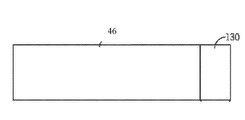
[0014] 도 2는 로터리 IPX(30)의 실시예의 분해도이다. 예시된 실시예에서, 로터리 IPX(30)는 하우징(44) 및 회전자(46)를 포함하는 일반적으로 원통형인 본체 부분(42)을 포함할 수 있다. 로터리 IPX(30)는 또한, 매니폴드들(54 및 52)을 각각 포함할 수 있는 2개의 단부 구조물들(46 및 50)을 포함할 수 있다. 매니폴드(52)는 입구 및 출구 포트들(58 및 56)을 포함하며, 그리고 매니폴드(54)는 입구 및 출구 포트들(60 및 62)을 포함한다. 예를 들어, 입구 포트(58)는 고압의 제1 유체를 수용할 수 있으며, 그리고 출구 포트(56)는 저압의 제1 유체를 IPX(30)로부터 멀리 내보는 데 사용될 수 있다. 유사하게는, 입구 포트(60)는 저압의 제2 유체를 수용할 수 있으며, 그리고 출구 포트(62)는 고압의 제2 유체를 IPX(30)로부터 멀리 내보는 데 사용될 수 있다. 단부 구조물들(46 및 50)은, 매니폴드들(50 및 46) 내에 배치되고 그리고 회전자(46)와의 유체 밀봉식으로 접촉을 위해 적응되는 일반적으로 평탄한 단부 플레이트들(예컨대, 단부 커버들)(66 및 64)을 각각 포함한다. 상기 유의된 바와 같이, 회전자(46)와 같은 IPX(30), 단부 플레이트(66), 및/또는 단부 플레이트(64) 중 하나 이상의 컴포넌트들은, 미리 정해진 임계치(예컨대, 적어도 1000, 1250, 1500, 1750, 2000, 2250 또는 그 초과인 비커스 경도 수)보다 더 큰 경도를 갖는 내마모성 재료(예컨대, 카바이드, 초경 합금, 규소 카바이드, 텅스텐 카바이드 등)로 구성될 수 있다. 예를 들어, 텅스텐 카바이드는 보다 내구성이 있을 수 있고, 그리고 다른 재료들, 예컨대 알루미나 세라믹과 비교하여 연마 유체들에게 개선된 내마모성을 제공할 수 있다.2 is an exploded view of an embodiment of the
[0015] 회전자(46)는 원통형이고 그리고 하우징(44)에 배치될 수 있고, 그리고 회전자(46)의 길이 방향 축(68)을 중심으로한 회전을 위해 배열된다. 회전자(46)는 길이 방향 축(66)을 중심으로 대칭으로 배열되는 각각의 단부에서 개구들(74 및 72)을 갖는 회전자(46)를 통해 실질적으로 길이 방향으로 연장하는 복수의 채널들(70)을 가질 수 있다. 회전자(46)의 개구들(74 및 72)은, 회전 동안 개구들이 고압의 유체 및 저압의 유체를 각각의 매니폴드들(54 및 52)에 교번식으로 유압식으로 노출시키는 방식으로 단부 플레이트들(66 및 64)과의 유압 연통을 위해 배열된다. 침식성 프래킹 유체들과 접촉하는 이러한 시스템의 단부에서의 컴포넌트들은 특히 마모에 취약하다. 회전자(46)의 단부를 따르는 마모 구역(120)의 경우에, 이러한 마모의 예는 도 2에서 알게 된다.The
[0016] 본 발명의 일부 실시예들에서, 보호 표면 층은 침식성 요소들에 대한 높은 노출의 구역에서 기저 구조물에 결합된다. 텅스텐 카바이드로 만들어진 이전에 언급된 예와는 대조적으로, 대체 회전자(substitute rotor)는 기저 구조물을 위한 제1 세라믹, 및 표면 마모 보호 층을 위한 제2 세라믹을 활용하여 만들어질 수 있다. 일부 양태들에서, 표면 층은 사파이어이다. 일부 양태들에서, 기저 구조물은 알루미나이다. 이는 제조하기에 훨씬 더 용이한 기저 구조물을 위한 세라믹, 예컨대 알루미나의 사용을 허용한다.In some embodiments of the invention, the protective surface layer is bonded to the base structure in the region of high exposure to erosive elements. In contrast to the previously mentioned examples made of tungsten carbide, a substitute rotor can be made utilizing the first ceramic for the base structure and the second ceramic for the surface wear protection layer. In some aspects, the surface layer is sapphire. In some aspects, the underlying structure is alumina. This allows the use of ceramics such as alumina for the base structure which is much easier to manufacture.
[0017] 사파이어 표면 층은 임의의 적합한 방식으로 기저 구조물에 고정될 수 있다. 일부 양태들에서, 표면 층은 부식성 처리 화학반응들을 견딜 수 있는 결합 층에 의해 기저 세라믹 구조물에 부착된다. 일부 양태들에서, 부식성 처리 화학반응들은 프래킹 화학물질들에 관한 것이다. 일부 양태들에서, 결합 층은 브레이즈 층에 의해 형성된다. 일부 양태들에서, 브레이즈 층은 알루미늄 브레이징 층이다. 일부 양태들에서, 표면 층, 또는 스킨은, 서로 오버레잉될 수 있거나 래버린스 인터페이스를 가질 수 있거나, 서로 접할 수 있는 복수의 피스들로 구성된다.The sapphire surface layer can be secured to the base structure in any suitable manner. In some aspects, the surface layer is attached to the base ceramic structure by a bonding layer capable of withstanding corrosive treatment chemistries. In some aspects, the corrosive treatment chemistries relate to fraking chemicals. In some aspects, the bonding layer is formed by a braze layer. In some aspects, the braze layer is an aluminum brazing layer. In some aspects, the surface layer, or skin, consists of a plurality of pieces that can be overlaid with one another, have a labyrinth interface, or can abut one another.
[0018] 일부 양태들에서, 사파이어 표면 층은 임의의 적합한 온도에서 결합 브레이즈 층에 의해 기저 세라믹 구조물에 결합된다. 일부 양태들에서, 온도는 적어도 770℃이다. 일부 양태들에서, 온도는 적어도 800℃이다. 일부 양태들에서, 온도는 1200℃ 미만이다. 일부 양태들에서, 온도는 770℃ 내지 1200℃이다. 일부 양태들에서, 온도는 800℃ 내지 1200℃이다. 일부 양태들에서, 보다 높은 온도들에서 재료 특성 열화 염려들을 가질 수 있는 세라믹을 사용할 때, 사용되는 온도는 770℃ 내지 1000℃의 범위에 있을 수 있다.In some aspects, the sapphire surface layer is bonded to the base ceramic structure by a bond braze layer at any suitable temperature. In some embodiments, the temperature is at least 770 ° C. In some aspects, the temperature is at least 800 ° C. In some embodiments, the temperature is less than 1200 ° C. In some embodiments, the temperature is between 770 ° C and 1200 ° C. In some embodiments, the temperature is between 800 ° C. and 1200 ° C. In some aspects, when using a ceramic that may have material property deterioration concerns at higher temperatures, the temperature used may be in the range of 770 ° C to 1000 ° C.
[0019] 일부 양태들에서, 사파이어 표면 층은 적합한 환경에서, 본원에서 개시되는 온도들 중 임의의 온도를 포함하는 임의의 적합한 온도에서 결합 브레이즈 층에 의해 기저 세라믹 구조물에 결합된다. 일부 양태들에서, 이 환경은 산소가 공급되지 않는 환경이다. 일부 양태들에서, 이 환경은 산소가 없다. 일부 양태들에서, 이 환경은 산소의 결핍 상태이다. 일부 양태들에서, 이 환경은 진공이다. 일부 양태들에서, 이 환경은 1 x 10E-4 Torr보다 더 낮은 압력에 있다. 일부 양태들에서, 이 환경은 1 x 10E-5 Torr보다 더 낮은 압력에 있다. 일부 양태들에서, 이 환경은 아르곤(Ar) 분위기이다. 일부 양태들에서, 이 환경은 다른 불활성 가스들의 분위기이다. 일부 양태들에서, 이 환경은 수소(H2) 분위기이다.In some aspects, the sapphire surface layer is bonded to the base ceramic structure by a bond braze layer at any suitable temperature, including any of the temperatures disclosed herein, in a suitable environment. In some aspects, this environment is an oxygen free environment. In some aspects, this environment is oxygen free. In some aspects, this environment is in a state of lack of oxygen. In some aspects, this environment is a vacuum. In some aspects, this environment is at a pressure lower than 1 × 10 E-4 Torr. In some aspects, this environment is at a pressure lower than 1 × 10 E-5 Torr. In some aspects, this environment is an argon (Ar) atmosphere. In some aspects, this environment is an atmosphere of other inert gases. In some aspects, this environment is a hydrogen (H 2 ) atmosphere.
[0020] 일부 양태들에서, 사파이어 표면 층은, 브레이즈 층에 의해 본원에 개시되는 환경들 중 임의의 환경을 포함하는 적합한 환경에서 본원에 개시되는 온도들 중 임의의 온도들을 포함하는 임의의 적합한 온도에서 기저 세라믹 구조물에 결합된다. 일부 양태들에서, 브레이즈 층은 순수한 알루미늄이다. 일 실시예에서, 브레이즈 층은 89중량%보다 더 큰 금속성 알루미늄이다. 일부 양태들에서, 브레이즈 층은 89중량% 초과의 알루미늄을 갖는다. 일부 양태들에서, 브레이즈 층은 99중량%보다 더 큰 금속성 알루미늄이다. 일부 양태들에서, 브레이즈 층은 99중량% 초과의 알루미늄을 갖는다.In some aspects, the sapphire surface layer includes any suitable temperature, including any of the temperatures disclosed herein, in a suitable environment including any of the environments disclosed herein by the braze layer. Is bonded to the underlying ceramic structure. In some aspects, the braze layer is pure aluminum. In one embodiment, the braze layer is metallic aluminum greater than 89% by weight. In some aspects, the braze layer has more than 89 weight percent aluminum. In some embodiments, the braze layer is greater than 99% by weight metallic aluminum. In some aspects, the braze layer has more than 99% by weight aluminum.
[0021] 일부 양태들에서, 사파이어 표면 층은, 본원에 개시되는 알루미늄 브레이즈 층들 중 임의에 의해 형성되는 알루미늄 결합 층을 포함하는 알루미늄 결합 층에 의해, 본원에 개시되는 환경들 중 임의의 환경을 포함하는 적합한 환경에서 본원에 개시되는 온도들 중 임의의 온도들을 포함하는 임의의 적합한 온도에서 기저 세라믹 구조물에 결합된다. 일부 양태들에서, 알루미늄 결합 층은 확산 접합이 없다. 일부 양태들에서, 알루미늄 결합 층을 형성하는 공정은 확산 접합이 없다. 일부 양태들에서, 사파이어 층과 알루미늄 결합 층 사이의 확산 접합이 존재하지 않는다. 일부 양태들에서, 알루미늄 결합 층은 사파이어 표면 층과 세라믹 구조물 사이에 밀폐식 시일을 형성한다. 일부 양태들에서, 알루미늄 결합 층은 <1 x 10E-9 sccm He/sec의 진공 누출 속도를 가지는 사파이어 표면 층과 세라믹 구조물 사이에 밀폐식 시일을 형성한다. 일부 양태들에서, 알루미늄 결합 층은 부식성 처리 화학반응들을 견딜 수 있다. 일부 양태들에서, 부식성 처리 화학반응들은 프래킹 화학물질들이다.In some aspects, the sapphire surface layer includes any of the environments disclosed herein, by an aluminum bonding layer comprising an aluminum bonding layer formed by any of the aluminum braze layers disclosed herein. To a base ceramic structure at any suitable temperature, including any of the temperatures disclosed herein, in a suitable environment. In some aspects, the aluminum bonding layer is free of diffusion bonding. In some aspects, the process of forming the aluminum bonding layer is free of diffusion bonding. In some aspects, there is no diffusion junction between the sapphire layer and the aluminum bonding layer. In some aspects, the aluminum bonding layer forms a hermetic seal between the sapphire surface layer and the ceramic structure. In some aspects, the aluminum bonding layer forms a hermetically sealed seal between the ceramic structure and the sapphire surface layer having a vacuum leak rate of <1 × 10 E-9 sccm He / sec. In some aspects, the aluminum bonding layer can withstand corrosive treatment chemistries. In some aspects, the corrosive treatment chemistries are fracturing chemicals.
[0022] 기저 세라믹 구조물은, 질화알루미늄, 산화알루미늄, 또는 알루미나, 사파이어, 산화이트륨, 지르코니아, 및 산화베릴륨을 포함하는 임의의 적합한 재료로 만들어질 수 있다.The base ceramic structure may be made of any suitable material, including aluminum nitride, aluminum oxide, or alumina, sapphire, yttrium oxide, zirconia, and beryllium oxide.
[0023] 위에서 알게 된 바와 같이, 브레이즈 층의 두께는 다양한 재료들 사이의 열팽창의 차별적인 계수들로 인해 응력들을 견딜 수 있도록 적응된다. 잔류 응력들은 아래에서 설명된 브레이징 단계들로부터 냉각(cool down) 동안 초래될 수 있다. 또한, 실온으로부터 상승하는 빠른 초기의 온도는 조립체에 걸쳐 일부 온도 비균일성을 유발시킬 수 있으며, 이는 브레이징 동안 발생되는 잔류 응력들로 악화될 수 있다.As noted above, the thickness of the braze layer is adapted to withstand stresses due to the differential coefficients of thermal expansion between the various materials. Residual stresses may result during cool down from the brazing steps described below. In addition, a rapid initial temperature rising from room temperature can cause some temperature non-uniformity across the assembly, which can be exacerbated by residual stresses generated during brazing.
[0024] 알루미늄은 산화된 알루미늄의 자체-제한 층(self-limiting layer)을 형성하는 특성을 갖는다. 이러한 층은 일반적은 균일하고, 그리고 일단 형성된다면, 베이스 알루미늄을 관통하고 그리고 산화 공정을 연속하는 부가의 산소 또는 다른 산화 화학반응들(이러한 불소 화학반응들)을 방지하거나 상당히 제한한다. 이러한 방식으로, 그 후 알루미늄의 표면 상에 형성되어 있는 산화물(또는 불소) 층에 의해 실질적으로 정지되거나 느려지는 알루미늄의 초기의 단기간의 산화 또는 부식이 존재한다. 브레이즈 재료는 포일 시트, 분말, 박막의 형태이거나, 본원에서 설명되는 브레이징 공정들에 대한 적합한 임의의 다른 형태 인자를 가질 수 있다. 예를 들어, 브레이징 층은 0.00019인치 내지 0.011인치 또는 그 초과의 범위에 있는 두께를 가지는 시트일 수 있다. 일부 실시예들에서, 브레이즈 재료는 대략 0.0012인치의 두께를 가지는 시트일 수 있다. 일부 실시예들에서, 브레이즈 재료는 대략 0.006인치의 두께를 가지는 시트일 수 있다. 통상적으로, 알루미늄에서의 (예를 들어, 마그네슘과 같은) 합금 구성성분들은 알루미늄의 입자 경계들 중간의 침전물들로서 형성된다. 이들이 알루미늄 접합 층의 산화 내성을 감소시킬 수 있는 한편, 통상적으로 이러한 침전물들은 알루미늄을 통해 연속적인 경로들을 형성하지 않으며, 그리고 이에 의해, 전체 알루미늄 층을 통해 산화제들의 관통을 허용하지 않고, 그리고 따라서 그의 부식 저항을 제공하는 알루미늄의 자체-제한하는 산화물-층 특성을 온전한 상태로 남겨진다. 침전물들을 형성할 수 있는 구성성분들을 보유하는 알루미늄 합금을 사용하는 실시예들에서, 냉각 프로토콜들을 포함하는 공정 매개변수들은 입자 경계에서의 침전물들을 최소화하도록 적응될 것이다. 예를 들어, 일부 양태들에서, 브레이즈 재료는 적어도 99.5%의 순도를 가지는 알루미늄일 수 있다. 일부 실시예들에서, 92%의 순도를 가질 수 있는 상업적으로 이용가능한 알루미늄 포일이 사용될 수 있다. 일부 실시예들에서, 합금들이 사용된다. 이러한 합금들은 Al-5w%Zr, Al-5w%Ti, 상업용 합금들(#7005, #5083, 및 #7075)을 포함할 수 있다. 이러한 합금들은 일부 실시예들에서 1100℃의 결합 온도로 사용될 수 있다. 이러한 합금들은 일부 실시예들에서 800℃ 내지 1200℃의 온도로 사용될 수 있다. 이러한 합금들은 일부 실시예들에서 보다 낮은 또는 보다 높은 온도로 사용될 수 있다. 일부 양태들에서, 결합 층 브레이즈 재료는 99중량%보다 더 큰 알루미늄일 수 있다. 일부 양태들에서, 결합 층 브레이즈 재료는 98중량%보다 더 큰 알루미늄일 수 있다.Aluminum has the property of forming a self-limiting layer of oxidized aluminum. This layer is generally uniform and, once formed, prevents or significantly limits additional oxygen or other oxidative chemistries (such fluorine chemistries) that penetrate the base aluminum and continue the oxidation process. In this way there is then an initial short-term oxidation or corrosion of aluminum which is substantially stopped or slowed down by an oxide (or fluorine) layer formed on the surface of the aluminum. The braze material may be in the form of a foil sheet, powder, thin film, or have any other form factor suitable for the brazing processes described herein. For example, the brazing layer can be a sheet having a thickness in the range of 0.00019 inches to 0.011 inches or more. In some embodiments, the braze material may be a sheet having a thickness of approximately 0.0012 inches. In some embodiments, the braze material may be a sheet having a thickness of approximately 0.006 inches. Typically, alloying constituents (such as magnesium, for example) in aluminum are formed as precipitates in the middle of the grain boundaries of aluminum. While they can reduce the oxidation resistance of the aluminum bonding layer, typically these precipitates do not form continuous paths through the aluminum, and thereby do not allow penetration of oxidants through the entire aluminum layer, and thus The self-limiting oxide-layer properties of aluminum that provide corrosion resistance are left intact. In embodiments using an aluminum alloy having components capable of forming precipitates, process parameters including cooling protocols will be adapted to minimize deposits at the grain boundaries. For example, in some aspects the braze material can be aluminum having a purity of at least 99.5%. In some embodiments, a commercially available aluminum foil may be used that may have a purity of 92%. In some embodiments, alloys are used. Such alloys may include Al-5w% Zr, Al-5w% Ti, commercial alloys (# 7005, # 5083, and # 7075). Such alloys may be used with a bonding temperature of 1100 ° C. in some embodiments. Such alloys may be used at temperatures of 800 ° C. to 1200 ° C. in some embodiments. Such alloys may be used at lower or higher temperatures in some embodiments. In some aspects, the bonding layer braze material may be aluminum greater than 99% by weight. In some aspects, the bonding layer braze material may be aluminum greater than 98% by weight.
[0025] 본 발명의 일부 실시예들에 따른 결합 방법들은, 결합될 세라믹 피스들에 대한 결합 재료의 습윤(wetting) 및 유동의 제어에 의존한다. 일부 실시예들에서, 결합 프로세스 중 산소의 부재는, 조인트 영역에서 재료들을 변화시키는 반응들 없이 적절한 습윤을 허용한다. 결합 재료의 적절한 습윤 및 유동에 의해, 밀폐식으로 밀봉된 조인트는, 예를 들어, 액상 소결에 대해 저온으로 얻어질 수 있다.Bonding methods according to some embodiments of the present invention rely on control of the wetting and flow of the bonding material to the ceramic pieces to be joined. In some embodiments, the absence of oxygen during the bonding process allows for proper wetting without reactions that change the materials in the joint region. By appropriate wetting and flowing of the bonding material, a hermetically sealed joint can be obtained at low temperature, for example, for liquid phase sintering.
[0026] 브레이징 공정 동안의 산소 또는 질소의 상당한 양의 존재는, 결국 밀폐식이 아닌 조인트를 유발할 수 있는 결합 인터페이스 구역의 완전한 습윤을 간섭하는 반응들을 생성할 수 있다. 완전한 습윤 없이, 비습윤된 구역들은 조인트 인터페이스 구역에서 최종 조인트로 도입된다. 충분한 연속적인 비습윤된 구역들이 도입될 때, 조인트의 밀폐가 손실된다.The presence of a significant amount of oxygen or nitrogen during the brazing process can create reactions that interfere with the complete wetting of the bond interface zone, which can eventually lead to a non-closed joint. Without complete wetting, the non-wetted zones are introduced into the final joint at the joint interface zone. When sufficient continuous non-wet zones are introduced, the closure of the joint is lost.
[0027] 일부 실시예들에서, 결합 공정은 매우 낮은 압력들을 제공하도록 적응되는 공정 챔버에서 수행된다. 본 발명의 실시예들에 따른 결합 공정들은 밀폐식으로 밀봉된 조인트를 달성하기 위해 산소의 결핍을 요구할 수 있다. 일부 실시예들에서, 공정은 1 x 10E-4 Torr보다 더 낮은 압력으로 수행된다. 일부 실시예들에서, 공정은 1 x 10E-5 Torr보다 더 낮은 압력으로 수행된다.In some embodiments, the bonding process is performed in a process chamber that is adapted to provide very low pressures. Coupling processes in accordance with embodiments of the present invention may require a lack of oxygen to achieve a hermetically sealed joint. In some embodiments, the process is performed at a pressure lower than 1 × 10 E-4 Torr. In some embodiments, the process is performed at a pressure lower than 1 × 10 E-5 Torr.
[0028] 질소의 존재는, 질화알루미늄을 형성하기 위해 용융된 알루미늄과의 질소 반응으로 이어질 수 있으며, 그리고 이러한 반응 형성은 조인트 인터페이스 구역의 습윤을 간섭할 수 있다. 유사하게는, 산소의 존재는, 산화알루미늄을 형성하기 위해 용융된 알루미늄과의 산소 반응으로 이어질 수 있으며, 그리고 이러한 반응 형성은 조인트 인터페이스 구역의 습윤을 간섭할 수 있다. 5 x 10⁻⁵ Torr보다 낮은 압력의 진공 분위기를 사용하는 것은, 조인트 인터페이스 구역의 완전히 견고한 습윤, 및 밀폐식 조인트들을 허용하기 위해 충분한 산소 및 질소를 제거했던 것으로 도시되었다. 일부 실시예들에서, 하지만 수소와 같은 비산화 가스들 또는 아르곤과 같은 순수 불활성 가스들을 사용하여, 예를 들어 브레이징 단계 동안 공정 챔버에서 분위기 압력을 포함하는 압력 보다 높은 압력들의 사용은 또한, 조인트 인터페이스 구역의 견고한 습윤, 및 밀폐식 조인트들로 이어졌다. 위에서 지칭되는 산소 반응을 회피하기 위해, 브레이징 공정 동안 공정 챔버에서의 산소의 양은, 조인트 인터페이스 구역의 완전한 습윤이 악영향이 주어지지 않도록 충분히 낮아야 한다. 위에서 지칭되는 질소 반응을 회피하기 위해, 브레이징 공정 동안 공정 챔버에 존재하는 질소의 양은, 조인트 인터페이스 구역의 완전한 습윤이 악영향이 주어지지 않도록 충분히 낮아야 한다.The presence of nitrogen can lead to a nitrogen reaction with molten aluminum to form aluminum nitride, which can interfere with the wetting of the joint interface region. Similarly, the presence of oxygen can lead to an oxygen reaction with molten aluminum to form aluminum oxide, which can interfere with the wetting of the joint interface region. Using a vacuum atmosphere with a pressure lower than 5 x 10⁻⁵ Torr has been shown to have removed sufficient oxygen and nitrogen to allow for completely firm wetting of the joint interface zone, and hermetically sealed joints. In some embodiments, however, using non-oxidizing gases such as hydrogen or pure inert gases such as argon, the use of pressures higher than the pressure including the atmospheric pressure in the process chamber, for example during the brazing step, may also be a joint interface. Solid wetting of the zone, and hermetic joints. To avoid the oxygen reaction referred to above, the amount of oxygen in the process chamber during the brazing process should be low enough so that complete wetting of the joint interface zone is not adversely affected. To avoid the nitrogen reaction referred to above, the amount of nitrogen present in the process chamber during the brazing process should be low enough so that complete wetting of the joint interface zone is not adversely affected.
[0029] 최소 조인트 두께를 유지하는 것과 커플링되는, 브레이징 공정 동안 적합한 분위기의 선택은 조인트의 완전한 습윤을 허용할 수 있다. 반대로, 부적합한 분위기의 선택은 조악한 습윤, 보이드들, 및 비밀폐식 조인트로 이어질 수 있다. 브레이징하는 동안 적합한 재료 선택 및 온도와 함께 제어된 분위기 및 제어된 조인트 두께의 적합한 조합은 밀폐식 조인트들과의 재료들의 결합을 허용한다.Selection of a suitable atmosphere during the brazing process, coupled with maintaining a minimum joint thickness, may allow complete wetting of the joint. In contrast, the selection of an inadequate atmosphere can lead to coarse wetting, voids, and hermetic joints. A suitable combination of controlled atmosphere and controlled joint thickness with suitable material selection and temperature during brazing allows the coupling of materials with hermetically sealed joints.
[0030] 일부 양태들에서, 기저 구조 세라믹은 표면 층에 대한 열팽창의 그의 계수에서 클로즈 매치(close match)를 제시하도록 선택된다. 열팽창의 계수들은 온도에 따라 변할 것이어서, 열팽창의 매칭 계수들의 선택은, 지지되도록 추구되는 처리 온도들을 통해 그리고 추가적으로 결합 층의 브레이징 온도에 이르기까지 실온으로부터 매치의 정도를 고려해야 한다.In some aspects, the base structure ceramic is selected to present a close match in its coefficient of thermal expansion to the surface layer. The coefficients of thermal expansion will vary with temperature, so the choice of matching coefficients of thermal expansion should take into account the degree of match from room temperature through the processing temperatures sought to be supported and further up to the brazing temperature of the bonding layer.
[0031] 예시적인 실시예에서, 표면 층은 사파이어이며, 그리고 기저 구조물이 알루미나이다. 20℃(293K), 517℃(800K), 및 1017℃(1300K) 각각에서의 사파이어(단결정 산화알루미늄)의 열팽창의 계수는 5.38, 8.52, 및 9.74 x 10E-6/K이다. 20℃, 500℃, 및 1000℃ 각각에서의 소결된 알루미나의 열팽창의 계수는 4.6, 7.1, 및 8.1 x 10E-6/K이다. 이들은 양호한 매칭을 제시한다. 예시적인 실시예에서, 브레이징 층은 89% 초과의 순도를 갖는 알루미늄이고, 99중량% 초과의 Al일 수 있다.In an exemplary embodiment, the surface layer is sapphire and the underlying structure is alumina. The coefficients of thermal expansion of sapphire (single crystal aluminum oxide) at 20 ° C (293K), 517 ° C (800K), and 1017 ° C (1300K), respectively, are 5.38, 8.52, and 9.74 x 10E-6 / K. The coefficients of thermal expansion of sintered alumina at 20 ° C., 500 ° C., and 1000 ° C., respectively, are 4.6, 7.1, and 8.1 × 10 E-6 / K. These suggest good matching. In an exemplary embodiment, the brazing layer is aluminum with a purity of greater than 89% and may be greater than 99% by weight of Al.
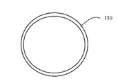
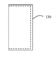
[0032] 도 3은 본 발명의 일부 실시예들에 따른 회전자(86)를 예시한다. 회전자(86)는 기저 구조물(87) 및 단부 캡(130)을 갖는다. 기저 구조물(87)은 알루미나일 수 있으며, 그리고 단부 캡(130)은 사파이어일 수 있다. 단부 캡(130)은 전술된 방법들에 따른 알루미늄 결합 층을 갖는 기저 구조물(87)에 결합될 수 있다. 기저 구조물(87)은 줄어든 직경 및 단부 캡(130)과 간섭하는 단부를 갖는 원통형이다. 단부 캡(130)은 원형 단부 플레이트를 갖는 실린더이다. 기저 구조물(87) 위에 있는 단부 캡(130)의 사용의 경우에, 회전자(86)는, 다른 접근법들에서 이전에 아는 것보다 심지어 보다 큰 내마모성을 갖는 알루미나와 같은 보다 실제적인 재료를 사용하여 제조될 수 있다.3 illustrates a rotor 86 in accordance with some embodiments of the present invention. The rotor 86 has a
[0033] 일부 양태들에서, 단부 슬리브는 회전자 위에서 사용될 수 있다. 일부 양태들에서, 원형 단부 캡은 회전자와 함께 사용될 수 있다. 일부 양태들에서, 단부 슬리브 및 원형 단부 캡은 회전자와 함께 사용될 수 있다.In some aspects, the end sleeve can be used over the rotor. In some aspects, a circular end cap can be used with the rotor. In some aspects, the end sleeve and the circular end cap can be used with the rotor.
[0034] 다른 예시적인 실시예에서, 길이 방향 채널들(70)은 사파이어와 같은 높은 내마모성 재료의 원통형 라이닝들과 나란히 정렬될 수 있다. 사파이어 원통형 라이닝들은 전술된 결합 방법들에 따라 회전자 기저 구조물에 브레이징될 수 있다.In another exemplary embodiment, the longitudinal channels 70 may be aligned side by side with the cylindrical linings of a high wear resistant material, such as sapphire. Sapphire cylindrical linings can be brazed to the rotor base structure according to the joining methods described above.
[0035] 알루미나와 같은 보다 실제적인 세라믹의 기저 구조물 위에 있는 예컨대, 사파이어의 높은 내마모성 표면 층들의 사용은 높은 마모 침식 환경들에 노출된 컴포넌트들에 대한 현재 접근법에 대해 상당한 개선을 제공한다. 알루미나에 대한 사파이어의 양호한 열팽창 매치는 재료들의 양호한 페어링(pairing)을 제공한다.[0035] The use of, for example, high wear resistant surface layers of sapphire over a more practical ceramic base structure such as alumina provides a significant improvement over current approaches for components exposed to high wear erosion environments. A good thermal expansion match of sapphire to alumina provides good pairing of the materials.
[0036] 위에서 언급된 접합 공정의 낮은 온도는 사파이어 이외에도, Mg-PSZ, 질화 규소, 및 YTZ 재료들의 사용을 가능하게 한다. 다른 재료들에 MgPSZ를 접합하기 위한 현재 공지된 공정은 >1200℃의 금속화를 요구한다. 소정의 온도에서 또는 1200℃ 초과에서 이러한 공정들 동안, MgPSZ 상의 강인화 상(toughening phase)이 정방정계 지르코니아 형성 정방형 지르코니아로 열화된다. 재료는 열적 노화(overaging)에 의해 열화된다. 적정한 MgPSZ는, 높은 마모 적용들이 재료 상의 연마제들의 마모 경화 효과로 인한 것이라는 점에서, 양호한 재료이다. MgPSZ이 연마에 의해 마모됨에 따라, MgPSZ는 지르코니아 내에 상변이로부터 표면 압축 응력을 발생시킨다. 스크래칭될(scratched) 때, 정방정계 지르코니아는 단사정계 지르코니아로 붕괴하고, 그리고 체적 팽창은 압축 표면 응력을 생성하는 지르코니아에서 발생한다. 이는 세라믹의 연마 저항(abrasion resistance)을 개선시킨다. 본 발명에 따른 공정들은, 재료들을 열화하지 않고 MpPSZ를 알루미나에 접합할 수 있는 단지 하나의 공정일 수 있다.The low temperature of the bonding process mentioned above enables the use of Mg-PSZ, silicon nitride, and YTZ materials, in addition to sapphire. Currently known processes for bonding MgPSZ to other materials require metallization of> 1200 ° C. During these processes at a predetermined temperature or above 1200 ° C., the toughening phase on the MgPSZ degrades into tetragonal zirconia forming square zirconia. The material is degraded by thermal overaging. Proper MgPSZ is a good material in that high wear applications are due to the wear hardening effect of the abrasives on the material. As MgPSZ wears off by polishing, MgPSZ generates surface compressive stress from phase transitions in zirconia. When scratched, tetragonal zirconia collapses into monoclinic zirconia, and volume expansion occurs in zirconia, which produces compressive surface stresses. This improves the abrasion resistance of the ceramic. The processes according to the present invention may be just one process capable of bonding MpPSZ to alumina without degrading the materials.
[0037] 일부 양태들에서, 높은 침식성 및/또는 높은 부식성 작동 환경을 겪는 컴포넌트들을 설계하고 제조하는 방법은 많은 산업용 적용들에서 경질 재료들 예컨대 진보된 세라믹들, 금속-매질-복합체들, 및 서멧들(cermets)을 활용하는 단계를 포함한다. 이러한 재료들의 특성들은 성능에서의 이익들 및 부식성, 고온, 및/또는 연마 환경들이 존재하는 적용들에서의 수명을 제공한다. 그러나, 이러한 재료들의 다른 특성은, 많은 경우들에서 이러한 재료들이 함께 결합하기에 어렵다는 점이다. 이러한 재료들을 이들 자체에 그리고 다른 재료들에 결합하기 위해 현재 사용 중인 통상적인 방법들은 접착제들, 글래싱(glassing), 능동식 브레이징, 직접적인 접합, 및 확산 접합을 포함한다. 이러한 방법들 모두는, 작동 온도, 내식성, 또는 상이한 열팽창 계수들의 결합 재료들에서 제한들을 갖는다. 예를 들어, 접착제들은 상승된 온도에서 사용될 수 없고, 제한된 내식성을 갖는다. 능동식 브레이징은 조악한 내식성을 가지며; 유리들은 제한된 내식성을 가지고, 그리고 임의의 열팽창 불일치를 견딜 수 없다. 직접적인 접합 및 확산 접합은 또한, 임의의 열팽창 불일치를 견딜 수 없을 뿐만 아니라, 값비싸고 어려운 공정들일 수 있다. 이러한 재료들 중 많은 재료들의 다른 특성은, 이 재료들이 제조하기에 어렵고 값이 비싸며; 이들의 본질상, 이 재료들은 극도로 경질이다. 요구되는 기하학적 형상들로 이 재료들을 성형하는 것은 종종 다이아몬드 툴링(diamond tooling)으로의 수백 시간들의 그라인딩을 요구할 수 있다. 가장 강하고 가장 경질인 이러한 재료들 중 일부 재료들, 예를 들어, 사파이어 및 부분적으로 안정화된 지르코니아(PSZ 또는 세라믹 강으로 공지됨)는, 이 재료들이 극도로 제한된 산업 적용들을 가지는 경우에 작업하기에 매우 비싸고 어렵다.In some aspects, a method of designing and manufacturing components that suffer from high erosion and / or high corrosive operating environments may involve hard materials such as advanced ceramics, metal-medium-composites, and cermets in many industrial applications. Utilizing cermets. The properties of these materials provide benefits in performance and longevity in applications where corrosive, high temperature, and / or abrasive environments exist. However, another property of these materials is that in many cases these materials are difficult to join together. Conventional methods currently in use for bonding such materials to themselves and to other materials include adhesives, glassing, active brazing, direct bonding, and diffusion bonding. All of these methods have limitations in operating materials, corrosion resistance, or coupling materials of different coefficients of thermal expansion. For example, adhesives cannot be used at elevated temperatures and have limited corrosion resistance. Active brazing has poor corrosion resistance; The glasses have limited corrosion resistance and cannot tolerate any thermal expansion mismatch. Direct bonding and diffusion bonding are also not only able to withstand any thermal expansion mismatch, but can also be expensive and difficult processes. Other properties of many of these materials are difficult and expensive for these materials to manufacture; By their nature these materials are extremely hard. Molding these materials into the required geometric shapes can often require hundreds of hours of grinding into diamond tooling. Some of the strongest and hardest of these materials, such as sapphire and partially stabilized zirconia (also known as PSZ or ceramic steel), are suitable for work where these materials have extremely limited industrial applications. Very expensive and difficult.
[0038] 채광 및 석유 탐사에서, 고도의 연마 슬러리들은 지하로부터 펌핑되어야 한다. 유사하게는, 프래킹이 고압 연마 슬러리들을 운반하기 위해 압력 교환 유닛들을 활용함에 따라, 채광 및 석유 탐사는 슬러리 펌핑 및 전달을 위한 상이한 장치의 호스트(host)를 활용한다. 이러한 펌핑 시스템들의 내부 컴포넌트들은 때때로 알루미나와 같은 진보된 세라믹으로 만들어진다. 이러한 적용들에서 PSZ의 사용의 경우에, 상당한 수명 및 성능 이점들이 초래될 수 있다. PSZ에 특정하여, 그의 재료 특성들 중 하나는 극도로 높은 내부 응력이며 ─ 이는 부분적으로 그의 큰 강도 및 연마 저항을 제공하는 것이다. 그러나, 이는, 내부 응력들로 인해, 재료가 치수적으로 안정적이지 않음에 따라, 고정밀 기계 컴포넌트들을 제조하는 것을 매우 어렵게(사실상 불가능하게) 만든다. 사용자가 정확한 형상들 및 치수들로 그라인딩하는 것을 시도함에 따라, 재료는 이동해서, 정밀한 부품들은 PSZ로 만들어질 수 없다. 필요한 것은, 현재 재료들의 비용에 가까운 비용으로 가장 좋은 재료들, 이러한 경우에, PSZ의 특성들을 활용하는 방법이다.In mining and petroleum exploration, highly abrasive slurries must be pumped from underground. Similarly, mining and petroleum exploration utilize a host of different devices for slurry pumping and delivery, as fringing utilizes pressure exchange units to carry high pressure abrasive slurries. The internal components of these pumping systems are sometimes made of advanced ceramics such as alumina. In the case of the use of PSZ in such applications, significant life and performance benefits can be brought about. Specific to PSZ, one of its material properties is an extremely high internal stress—which in part provides its great strength and abrasive resistance. However, this makes it very difficult (virtually impossible) to manufacture high precision mechanical components as the material is not dimensionally stable due to internal stresses. As the user attempts to grind to the correct shapes and dimensions, the material moves so that precise parts cannot be made of PSZ. What is needed is a method of utilizing the properties of the best materials, in this case PSZ, at a cost close to the cost of current materials.
[0039] 예를 들어, 프래킹, 채광, 및 석유 탐사, 슬러리의 연마로 인한 마모를 겪는 회전자들, 베어링들, 단부 캡들 등과 같은 컴포넌트들에서의 연마 슬러피 펌핑 적용들의 경우에, 알루미늄 브레이징의 이전에 언급된 공정은 PSZ 또는 사파이어의 “스킨”, 또는 마모 표면 층을 알루미나의 구조물 상에 결합하도록 활용된다. 이러한 접근법을 활용하여, PSZ의 층이 견고하게 결합되는 기저 알루미나 구조물은 필요한 기하학적 형상들을 달성하도록 요구되는 치수 안정성을 제공한다. PSZ는, 연마 저항 성능이 필요하다면, 연마 저항 성능을 제공하며, 그리고 알루미나의 제조능력 및 비용들은 대부분의 구조물을 제공하는 데 사용된다. 비록 사파이어의 비용 증가 및 PSZ의 연마 저항이 일부 경우들에서 PSZ를 보다 양호하게 선택하지만, 사파이어는 또한 사용될 수 있다. 다른 예들에서, 컴포넌트들은 텅스텐 카바이드, 및 극도로 경질인 세라믹 재료로 만들어진다. 이러한 컴포넌트들을 제조하는 것은 극도로 값비싸다. 마모하는 것으로 나타나는 위치들에서의 PSZ의 사용은 컴포넌트 수명을 상당하기 증가시킬 것이며, 그리고 마모를 겪지 않는 컴포넌트 구역들에서의 알루미나 세라믹 재료의 사용은 실질적으로 총 비용을 감소시킬 것이다.[0039] For example, in the case of abrasive sludge pumping applications in components such as rotors, bearings, end caps, and the like, which suffer from abrasion due to grinding, mining, and petroleum exploration, polishing of slurry, The previously mentioned process of is utilized to bond a "skin" of PSZ or sapphire, or a wear surface layer onto the structure of alumina. Using this approach, the underlying alumina structure, in which the layers of PSZ are firmly bonded, provides the dimensional stability required to achieve the required geometric shapes. PSZ provides abrasive resistance performance if needed, and the alumina manufacturing capabilities and costs are used to provide most of the structure. Although the increased cost of sapphire and the polishing resistance of PSZ select PSZ better in some cases, sapphire can also be used. In other examples, the components are made of tungsten carbide, and an extremely hard ceramic material. Manufacturing such components is extremely expensive. The use of PSZ in locations that appear to wear will significantly increase component life, and the use of alumina ceramic material in component areas that do not experience wear will substantially reduce total cost.
[0040] 예를 들어, 가스 플라즈마 분사 노즐들이 반도체 제조시에 사용되는 경우에, 작은 피스의 사파이어는 오리피스를 만드는 데 사용될 수 있다. 노즐의 나머지는, 사용시에 제조 방법들 및 비용들을 오리피스 없이 ─ 이미 활용하여 알루미나 또는 질화알루미늄에서 제조될 수 있다. 그 후, 사파이어 오리피스는 본원에서 설명된 알루미늄 브레이징 공정을 활용하여 제자리에 접합된다. 이러한 방식으로, 사파이어의 플라즈마 침식 저항은 원래의 알루미나 노즐의 제조능력 및 비용과 커플링된다.For example, where gas plasma spray nozzles are used in semiconductor manufacturing, a small piece of sapphire can be used to make an orifice. The remainder of the nozzle can be made from alumina or aluminum nitride, utilizing the manufacturing methods and costs at the time of use—without orifice—already utilized. The sapphire orifice is then bonded in place using the aluminum brazing process described herein. In this way, the plasma erosion resistance of sapphire is coupled with the manufacturing capacity and cost of the original alumina nozzle.
[0041] 반도체 제조시에, 부식성 및 고온 둘 모두인 고에너지 가스 플라즈마는 집적 회로들(integrated circuits)의 제조시에 필요한 처리를 실시하는 데 사용된다. 많은 적용들에서, 컴포넌트들은 플라즈마를 보유하고 그리고 지향시키기 위해 처리 환경에서 사용된다. 통상적으로, 에지 링들, 초점 링들, 가스 링들, 가스 판들, 블로커 판들 등으로 일반적으로 불리는 이러한 컴포넌트들은 석영, 규소, 알루미나, 또는 질화알루미늄으로 만들어진다. 플라즈마에 의한 부품들의 침식이 공정 드리프트(drift) 및 오염을 유발시킴에 따라, 시간 단위로 측정되는 수명을 가지는 이러한 컴포넌트들이 짧은 서비스 시간들 후에 컴포넌트들의 교체를 필요로 하는 것은 드문 일이 아니다. 일부 적용들에서, 플라즈마는 세라믹 노즐들의 어레이의 사용에 의해 처리 환경으로 분사된다. 이러한 노즐들은 플라즈마의 유량 및 패턴을 제어하기 위해 복잡한 기하학적 형상들을 갖는 그리고 대략 0.010” 직경의 작은 오리피스를 갖는 분사 노즐모놀리스형 부품들이다. 이러한 노즐들을 위한 통상적은 재료들은 산화알루미늄 또는 질화알루미늄이다. 심지어 이러한 진보된 세라믹의 사용의 경우에, 노즐들의 수명은 고에너지 플라즈마에 의한 오리피스의 침식으로 인해 3달이다. 이는, 기계가 20개 초과의 개별적인 노즐들을 통상적으로 포함하는 노즐 어레이를 교체하기 위해 3달마다 완전히 셧다운되는(shut down) 것을 요구한다. 노즐들이 침식되고 있으면서, 노즐들은 처리의 수율들을 감소시키는 플라즈마로 오염물들을 방출한다. 그리고 노즐들이 이들의 엔드-오프-라이프(end-of-life)에 도달함에 따라, 플라즈마의 유동은 오리피스의 침식으로 인해 증가하기 시작하며, 이는 공정 성능을 변경하는 것을 허용하여, 추가적으로 수율들을 감소시킨다. 사파이어 및 산화이트륨과 같은 다른 진보된 세라믹 재료들은 이러한 플라즈마 환경에서 상당히 보다 낮은 침식 속도들을 갖는다. 에지 링들 및 분사기 노즐들과 같은 컴포넌트들이 이러한 재료들로 만들어질 수 있다면, 상당한 수명 및 성능 개선들이 유발될 것이다. 그러나, 위에서 언급된 제조 및 비용 제한들로 인해, 어느 누구도 이러한 적용을 위해 이러한 재료들을 사용하지 않는다. 필요한 것은, 현재 재료들의 비용에 가까운 비용으로 가장 좋은 재료들의 특성들을 활용하는 방법이다.In semiconductor manufacturing, high energy gas plasmas, both corrosive and high temperature, are used to perform the processing required in the manufacture of integrated circuits. In many applications, components are used in a processing environment to hold and direct plasma. Typically, these components, commonly referred to as edge rings, focus rings, gas rings, gas plates, blocker plates, and the like, are made of quartz, silicon, alumina, or aluminum nitride. As erosion of components by plasma causes process drift and contamination, it is not uncommon for these components with lifespans measured in hours to require replacement of components after short service times. In some applications, the plasma is injected into the processing environment by the use of an array of ceramic nozzles. These nozzles are injection nozzle monolithic parts with complex geometries and small orifices of approximately 0.010 "diameter to control the flow rate and pattern of the plasma. Typical materials for such nozzles are aluminum oxide or aluminum nitride. Even in the case of the use of such advanced ceramics, the lifetime of the nozzles is three months due to the erosion of the orifice by the high energy plasma. This requires the machine to be fully shut down every three months to replace a nozzle array typically containing more than twenty individual nozzles. As the nozzles are eroding, the nozzles release contaminants into the plasma which reduce the yields of the treatment. And as the nozzles reach their end-of-life, the flow of plasma begins to increase due to the erosion of the orifice, which allows to change process performance, further reducing yields. Let's do it. Other advanced ceramic materials such as sapphire and yttrium oxide have significantly lower erosion rates in this plasma environment. If components such as edge rings and injector nozzles can be made of these materials, significant life and performance improvements will result. However, due to the manufacturing and cost restrictions mentioned above, no one uses these materials for this application. What is needed is a method of utilizing the properties of the best materials at a cost close to the cost of current materials.
[0042] 본 발명의 양태들은, 침식 및 부식을 위한 가장 좋은 재료들, 예컨대 사파이어(모노-결정질 산화알루미늄), 산화이트륨, 및 PSZ의 특성들을 조합하는 방법에 산화알루미늄과 같은 보다 낮은 비용의 진보된 세라믹 재료들을 제공한다. 진보된 세라믹 재료들을 그 자체에 그리고 다른 재료들에 결합하기 위한 브레이징 재료로서 알루미늄을 사용하는 본 발명의 실시예들에 따라 방법을 활용하여, 가장 높은 성능 진보된 세라믹 재료들의 특성들을 알루미나와 같은 세라믹의 보다 낮은 비용 및 간단한 제조능력의 비용들 및 제조 능력과 결합하는 것이 이제 가능하다. 이러한 공정들은 높은 레벨들의 부식 및 침식 저항을 갖는 조인트들을 제조하며, 이 조인트들은 상승된 온도들에서 작동할 수 있고 그리고 결합된 재료들 사이의 열팽창시에 상당한 변형들을 견딜 수 있다.Aspects of the invention are lower cost advancements such as aluminum oxide in a method that combines the best materials for erosion and corrosion, such as sapphire (mono-crystalline aluminum oxide), yttrium oxide, and PSZ. Ceramic materials. Utilizing the method according to embodiments of the present invention using aluminum as a brazing material for bonding advanced ceramic materials to itself and to other materials, the properties of the highest performance advanced ceramic materials can be characterized by ceramics such as alumina. It is now possible to combine the lower cost and simple cost of manufacturing with the cost and manufacturing capacity. These processes produce joints with high levels of corrosion and erosion resistance, which joints can operate at elevated temperatures and can withstand significant deformations in thermal expansion between the joined materials.
[0043] 전술된 바와 같은 컴포넌트들의 설계의 부분으로서, 세라믹의 열팽창 차이들은 검토될 것이다. 브레이즈 층의 두께, 및/또는 표면 세라믹 층의 두께는 브레이징 및 후속하는 냉각 동안, 그리고 사용 동안 응력 레벨들을 허용가능한 레벨들 미만으로 유지하도록 선택될 수 있다.As part of the design of the components as described above, thermal expansion differences of the ceramic will be considered. The thickness of the braze layer, and / or the thickness of the surface ceramic layer, may be selected to maintain stress levels below acceptable levels during brazing and subsequent cooling, and during use.
[0044] 위의 설명으로부터 명백한 바와 같이, 매우 다양한 실시예들은 본원에서 주어진 설명으로부터 구성될 수 있으며, 그리고 추가의 이점들 및 수정들이 당업자에게 용이하게 발생할 것이다. 따라서, 그의 보다 넓은 양태들에서의 본 발명은 도시되고 그리고 설명되는 특정한 상세들 및 예시적인 예들에 제한되지 않는다. 이에 따라, 이러한 상세들로부터의 이탈은 출원인의 일반적인 발명의 사상 또는 범주로부터 벗어나지 않고 이루어질 수 있다.As will be apparent from the above description, a wide variety of embodiments may be constructed from the description given herein, and further advantages and modifications will readily occur to those skilled in the art. Thus, the invention in its broader aspects is not limited to the specific details and illustrative examples shown and described. Accordingly, departures from these details may be made without departing from the spirit or scope of Applicant's general invention.
Claims (36)
단부를 가지고 그리고 제1 세라믹을 포함하는 원통형 펌프 샤프트(cylindrical pump shaft), 상기 원통형 펌프 샤프트의 단부 위에 있는 단부 캡(end cap) ─ 상기 단부 캡은 제2 세라믹을 포함함 ─, 및 상기 펌프 샤프트와 상기 단부 캡을 결합하는 결합 층을 포함하며, 상기 결합 층은 금속성 알루미늄을 포함하는,
유압식 파쇄 시스템을 위한 회전자 샤프트.Rotor shaft for hydraulic fracturing system,
A cylindrical pump shaft having an end and comprising a first ceramic, an end cap over an end of the cylindrical pump shaft, the end cap comprising a second ceramic, and the pump shaft And a bonding layer joining the end cap, the bonding layer comprising metallic aluminum,
Rotor shaft for hydraulic fracturing systems.
상기 원통형 펌프 샤프트는 그의 길이의 대부분에 대한 제1 직경 및 단부에서의 제2 직경을 더 가지며, 상기 제2 직경은 상기 제1 직경보다 더 작은,
유압식 파쇄 시스템을 위한 회전자 샤프트.According to claim 1,
The cylindrical pump shaft further has a first diameter for most of its length and a second diameter at the end, the second diameter being smaller than the first diameter,
Rotor shaft for hydraulic fracturing systems.
상기 단부 캡은 원통형 쉘을 포함하며, 상기 단부 캡의 외경은 상기 제1 직경인,
유압식 파쇄 시스템을 위한 회전자 샤프트.According to claim 1,
The end cap comprises a cylindrical shell, the outer diameter of the end cap being the first diameter,
Rotor shaft for hydraulic fracturing systems.
상기 제2 세라믹은 사파이어를 포함하는,
유압식 파쇄 시스템을 위한 회전자 샤프트.The method of claim 3, wherein
The second ceramic includes sapphire,
Rotor shaft for hydraulic fracturing systems.
상기 제1 세라믹은 알루미나를 포함하는,
유압식 파쇄 시스템을 위한 회전자 샤프트.The method of claim 4, wherein
Wherein the first ceramic comprises alumina,
Rotor shaft for hydraulic fracturing systems.
상기 결합 층은 99중량% 초과의 금속성 알루미늄을 포함하는,
유압식 파쇄 시스템을 위한 회전자 샤프트.The method of claim 5,
The bonding layer comprises greater than 99% by weight metallic aluminum,
Rotor shaft for hydraulic fracturing systems.
상기 단부 캡은 상기 원통형 쉘에 커플링되는 원형 단부 플레이트(circular end plate)를 더 포함하는,
유압식 파쇄 시스템을 위한 회전자 샤프트.The method of claim 3, wherein
The end cap further comprises a circular end plate coupled to the cylindrical shell;
Rotor shaft for hydraulic fracturing systems.
상기 제2 세라믹은 MpPSZ를 포함하는,
유압식 파쇄 시스템을 위한 회전자 샤프트.The method of claim 3, wherein
Wherein the second ceramic comprises MpPSZ,
Rotor shaft for hydraulic fracturing systems.
상기 제1 세라믹은 알루미나를 포함하는,
유압식 파쇄 시스템을 위한 회전자 샤프트.The method of claim 8,
Wherein the first ceramic comprises alumina,
Rotor shaft for hydraulic fracturing systems.
상기 결합 층은 99중량% 초과의 금속성 알루미늄을 포함하는,
유압식 파쇄 시스템을 위한 회전자 샤프트.The method of claim 9,
The bonding layer comprises greater than 99% by weight metallic aluminum,
Rotor shaft for hydraulic fracturing systems.
상기 제2 세라믹은 YTZ를 포함하는,
유압식 파쇄 시스템을 위한 회전자 샤프트.The method of claim 3, wherein
Wherein the second ceramic comprises YTZ,
Rotor shaft for hydraulic fracturing systems.
상기 제1 세라믹은 알루미나를 포함하는,
유압식 파쇄 시스템을 위한 회전자 샤프트.The method of claim 11, wherein
Wherein the first ceramic comprises alumina,
Rotor shaft for hydraulic fracturing systems.
상기 결합 층은 99중량% 초과의 금속성 알루미늄을 포함하는,
유압식 파쇄 시스템을 위한 회전자 샤프트.The method of claim 12,
The bonding layer comprises greater than 99% by weight metallic aluminum,
Rotor shaft for hydraulic fracturing systems.
상기 제2 세라믹은 사파이어를 포함하는,
유압식 파쇄 시스템을 위한 회전자 샤프트.According to claim 1,
The second ceramic includes sapphire,
Rotor shaft for hydraulic fracturing systems.
상기 제1 세라믹은 알루미나를 포함하는,
유압식 파쇄 시스템을 위한 회전자 샤프트.The method of claim 14,
Wherein the first ceramic comprises alumina,
Rotor shaft for hydraulic fracturing systems.
상기 제2 세라믹은 MpPSZ를 포함하는,
유압식 파쇄 시스템을 위한 회전자 샤프트.According to claim 1,
Wherein the second ceramic comprises MpPSZ,
Rotor shaft for hydraulic fracturing systems.
상기 제1 세라믹은 알루미나를 포함하는,
유압식 파쇄 시스템을 위한 회전자 샤프트.The method of claim 16,
Wherein the first ceramic comprises alumina,
Rotor shaft for hydraulic fracturing systems.
상기 제2 세라믹은 YTZ를 포함하는,
유압식 파쇄 시스템을 위한 회전자 샤프트.According to claim 1,
Wherein the second ceramic comprises YTZ,
Rotor shaft for hydraulic fracturing systems.
상기 제1 세라믹은 알루미나를 포함하는,
유압식 파쇄 시스템을 위한 회전자 샤프트.The method of claim 18,
Wherein the first ceramic comprises alumina,
Rotor shaft for hydraulic fracturing systems.
구조적 지지 부분, 하나 이상의 식별된 높은 마모 노출 표면들, 하나 이상의 보호 층들 및 상기 구조적 지지 부분의 상기 하나 이상의 보호 층들을 상기 하나 이상의 마모 노출 표면들에 결합하는 하나 이상의 결합 층들을 포함하며, 상기 하나 이상의 결합 층들은 금속성 알루미늄을 각각 포함하는,
높은 침식성 또는 부식성 환경에서의 사용을 위해 적응되는 산업용 컴포넌트.Industrial components adapted for use in highly corrosive or corrosive environments,
A structural support portion, one or more identified high wear exposed surfaces, one or more protective layers and one or more bonding layers coupling the one or more protective layers of the structural support portion to the one or more wear exposed surfaces, wherein the one The above bonding layers each include metallic aluminum,
Industrial components adapted for use in highly corrosive or corrosive environments.
상기 구조적 지지 부분은 알루미나를 포함하는,
높은 침식성 또는 부식성 환경에서의 사용을 위해 적응되는 산업용 컴포넌트.The method of claim 20,
Wherein the structural support portion comprises alumina,
Industrial components adapted for use in highly corrosive or corrosive environments.
상기 하나 이상의 보호 층들은 사파이어를 포함하는,
높은 침식성 또는 부식성 환경에서의 사용을 위해 적응되는 산업용 컴포넌트.The method of claim 21,
Wherein the one or more protective layers comprise sapphire,
Industrial components adapted for use in highly corrosive or corrosive environments.
상기 결합 층은 99중량% 초과의 금속성 알루미늄을 포함하는,
높은 침식성 또는 부식성 환경에서의 사용을 위해 적응되는 산업용 컴포넌트.The method of claim 22,
The bonding layer comprises greater than 99% by weight metallic aluminum,
Industrial components adapted for use in highly corrosive or corrosive environments.
상기 결합 층은 99중량% 초과의 금속성 알루미늄을 포함하는,
높은 침식성 또는 부식성 환경에서의 사용을 위해 적응되는 산업용 컴포넌트.The method of claim 21,
The bonding layer comprises greater than 99% by weight metallic aluminum,
Industrial components adapted for use in highly corrosive or corrosive environments.
하나 이상의 표면 마모 층들을 하나 이상의 브레이징 층들을 갖는 산업용 컴포넌트 주요 지지 구조물 상에 배열하는 단계 ─ 상기 하나 이상의 브레이징 층들은 상기 하나 이상의 표면 마모 층들과 상기 지지 구조물 사이에 배치되며, 상기 브레이징 층은 금속성 알루미늄을 포함함 ─, 프리-브레이징 서브 조립체(pre-brazing sub assembly)를 공정 챔버(process chamber)로 배치하는 단계, 상기 공정 챔버로부터 산소를 제거하는 단계, 그리고 770℃ 초과의 온도로 가열시킴으로써 상기 표면 마모 층들을 상기 주요 지지 구조물에 결합시키며, 이에 의해 밀폐식 조인트(hermetic joint)로 상기 표면 마모 층들을 상기 주요 지지 구조물에 결합하는 단계를 포함하는,
높은 침식성 환경에서의 사용을 위한 산업용 컴포넌트의 제조를 위한 방법.A method for the manufacture of industrial components for use in a highly corrosive environment,
Arranging one or more surface wear layers on an industrial component main support structure having one or more brazing layers, wherein the one or more braze layers are disposed between the one or more surface wear layers and the support structure, the brazing layer being metallic aluminum Comprising: disposing a pre-brazing sub assembly into a process chamber, removing oxygen from the process chamber, and heating the surface to a temperature above 770 ° C. Coupling wear layers to the main support structure, thereby joining the surface wear layers to the main support structure in a hermetic joint,
Method for the manufacture of industrial components for use in highly corrosive environments.
상기 공정 챔버로부터 산소를 제거하는 단계는 1 x 10E-4 미만의 압력으로 상기 컴포넌트들의 가열 동안 진공을 적용시키는 단계를 포함하는,
높은 침식성 환경에서의 사용을 위한 산업용 컴포넌트의 제조를 위한 방법.The method of claim 25,
Removing oxygen from the process chamber includes applying a vacuum during heating of the components at a pressure of less than 1 × 10 E-4.
Method for the manufacture of industrial components for use in highly corrosive environments.
상기 주요 지지 구조물은 질화알루미늄을 포함하는,
높은 침식성 환경에서의 사용을 위한 산업용 컴포넌트의 제조를 위한 방법.The method of claim 26,
The main support structure comprises aluminum nitride,
Method for the manufacture of industrial components for use in highly corrosive environments.
상기 하나 이상의 표면 층들은 사파이어를 포함하는,
높은 침식성 환경에서의 사용을 위한 산업용 컴포넌트의 제조를 위한 방법.The method of claim 27,
Wherein the one or more surface layers comprise sapphire,
Method for the manufacture of industrial components for use in highly corrosive environments.
상기 주요 지지 구조물은 알루미나를 포함하는,
높은 침식성 환경에서의 사용을 위한 산업용 컴포넌트의 제조를 위한 방법.The method of claim 26,
The main support structure comprises alumina,
Method for the manufacture of industrial components for use in highly corrosive environments.
상기 하나 이상의 표면 층들은 사파이어를 포함하는,
높은 침식성 환경에서의 사용을 위한 산업용 컴포넌트의 제조를 위한 방법.The method of claim 29,
Wherein the one or more surface layers comprise sapphire,
Method for the manufacture of industrial components for use in highly corrosive environments.
상기 브레이징 층은 99중량% 초과의 금속성 알루미늄을 포함하는,
높은 침식성 환경에서의 사용을 위한 산업용 컴포넌트의 제조를 위한 방법.The method of claim 30,
Wherein the brazing layer comprises more than 99% by weight metallic aluminum,
Method for the manufacture of industrial components for use in highly corrosive environments.
상기 하나 이상의 표면 층들은 MpPSZ를 포함하는,
높은 침식성 환경에서의 사용을 위한 산업용 컴포넌트의 제조를 위한 방법.The method of claim 28,
Wherein the one or more surface layers comprise MpPSZ,
Method for the manufacture of industrial components for use in highly corrosive environments.
상기 브레이징 층은 99중량% 초과의 금속성 알루미늄을 포함하는,
높은 침식성 환경에서의 사용을 위한 산업용 컴포넌트의 제조를 위한 방법.33. The method of claim 32,
Wherein the brazing layer comprises more than 99% by weight metallic aluminum,
Method for the manufacture of industrial components for use in highly corrosive environments.
상기 하나 이상의 표면 층들은 YTZ를 포함하는,
높은 침식성 환경에서의 사용을 위한 산업용 컴포넌트의 제조를 위한 방법.The method of claim 28,
Wherein the one or more surface layers comprise YTZ,
Method for the manufacture of industrial components for use in highly corrosive environments.
상기 브레이징 층은 99중량% 초과의 금속성 알루미늄을 포함하는,
높은 침식성 환경에서의 사용을 위한 산업용 컴포넌트의 제조를 위한 방법.The method of claim 34, wherein
Wherein the brazing layer comprises more than 99% by weight metallic aluminum,
Method for the manufacture of industrial components for use in highly corrosive environments.
상기 브레이징 층은 99중량% 초과의 금속성 알루미늄을 포함하는,
높은 침식성 환경에서의 사용을 위한 산업용 컴포넌트의 제조를 위한 방법.The method of claim 25,
Wherein the brazing layer comprises more than 99% by weight metallic aluminum,
Method for the manufacture of industrial components for use in highly corrosive environments.
Applications Claiming Priority (3)
| Application Number | Priority Date | Filing Date | Title |
|---|---|---|---|
| US201762474597P | 2017-03-21 | 2017-03-21 | |
| US62/474,597 | 2017-03-21 | ||
| PCT/US2018/023666 WO2018175665A1 (en) | 2017-03-21 | 2018-03-21 | Ceramic material assembly for use in highly corrosive or erosive industrial applications |
Publications (1)
| Publication Number | Publication Date |
|---|---|
| KR20190132425A true KR20190132425A (en) | 2019-11-27 |
Family
ID=63584678
Family Applications (2)
| Application Number | Title | Priority Date | Filing Date |
|---|---|---|---|
| KR1020197030563A KR20190132425A (en) | 2017-03-21 | 2018-03-21 | Ceramic material assembly for use in high corrosive or corrosive industrial applications |
| KR1020197030565A KR20190127863A (en) | 2017-03-21 | 2018-03-21 | Ceramic material assembly for use in highly corrosive or erosive semiconductor processing applications |
Family Applications After (1)
| Application Number | Title | Priority Date | Filing Date |
|---|---|---|---|
| KR1020197030565A KR20190127863A (en) | 2017-03-21 | 2018-03-21 | Ceramic material assembly for use in highly corrosive or erosive semiconductor processing applications |
Country Status (7)
| Country | Link |
|---|---|
| US (2) | US20190066980A1 (en) |
| EP (2) | EP3602603A4 (en) |
| JP (2) | JP2020512691A (en) |
| KR (2) | KR20190132425A (en) |
| CN (2) | CN110520628A (en) |
| TW (1) | TW201841869A (en) |
| WO (2) | WO2018175647A1 (en) |
Families Citing this family (3)
| Publication number | Priority date | Publication date | Assignee | Title |
|---|---|---|---|---|
| US10933375B1 (en) | 2019-08-30 | 2021-03-02 | Fluid Equipment Development Company, Llc | Fluid to fluid pressurizer and method of operating the same |
| KR102261947B1 (en) * | 2020-02-12 | 2021-06-08 | 에스케이씨솔믹스 주식회사 | Method for manufacturing a ceramic part for apparatus manufacturing a semiconductor device and a ceramic part |
| CN116084876A (en) * | 2023-03-28 | 2023-05-09 | 西南石油大学 | High wear-resisting and soluble tieback urceolus horn mouth and sealed face protective sheath |
Family Cites Families (33)
| Publication number | Priority date | Publication date | Assignee | Title |
|---|---|---|---|---|
| CA1235375A (en) * | 1984-10-18 | 1988-04-19 | Nobuo Tsuno | Turbine rotor units and method of producing the same |
| US4602731A (en) * | 1984-12-24 | 1986-07-29 | Borg-Warner Corporation | Direct liquid phase bonding of ceramics to metals |
| JPS6278172A (en) * | 1985-09-30 | 1987-04-10 | 日本特殊陶業株式会社 | Bonded structure of ceramic to metal |
| JPS6379777A (en) * | 1986-09-24 | 1988-04-09 | 科学技術庁金属材料技術研究所長 | Coating on ceramic substrate and manufacture |
| US5108025A (en) * | 1991-05-20 | 1992-04-28 | Gte Laboratories Incorporated | Ceramic-metal composite article and joining method |
| JP3447305B2 (en) * | 1991-07-30 | 2003-09-16 | 京セラ株式会社 | Electrostatic chuck |
| JPH06291175A (en) * | 1993-04-01 | 1994-10-18 | Kyocera Corp | Electrostatic chuck |
| US5685914A (en) * | 1994-04-05 | 1997-11-11 | Applied Materials, Inc. | Focus ring for semiconductor wafer processing in a plasma reactor |
| JP3687161B2 (en) * | 1995-11-21 | 2005-08-24 | 同和鉱業株式会社 | Joining method of ceramic structures |
| JPH09199578A (en) * | 1996-01-19 | 1997-07-31 | Hitachi Ltd | Electrostatic attraction electrode and prasma treatment equipment using the same |
| JPH09260472A (en) * | 1996-03-19 | 1997-10-03 | Sony Corp | Electrostatic chuck |
| JP2754194B2 (en) * | 1996-03-19 | 1998-05-20 | 工業技術院長 | Hydraulic crusher packer |
| JP3455026B2 (en) * | 1996-09-30 | 2003-10-06 | 京セラ株式会社 | Electrostatic chuck |
| FI101565B1 (en) * | 1997-01-17 | 1998-07-15 | Flaekt Oy | Evaporation fan and its impeller |
| US6129808A (en) * | 1998-03-31 | 2000-10-10 | Lam Research Corporation | Low contamination high density plasma etch chambers and methods for making the same |
| JP4651166B2 (en) * | 2000-06-30 | 2011-03-16 | 京セラ株式会社 | Corrosion resistant material |
| JP3920551B2 (en) * | 2000-09-29 | 2007-05-30 | 株式会社山武 | Joining method |
| US6620520B2 (en) * | 2000-12-29 | 2003-09-16 | Lam Research Corporation | Zirconia toughened ceramic components and coatings in semiconductor processing equipment and method of manufacture thereof |
| US7001543B2 (en) * | 2001-10-23 | 2006-02-21 | Kyocera Corporation | Apparatus and method for manufacturing semiconductor grains |
| FR2842903B1 (en) * | 2002-07-23 | 2004-11-19 | Schlumberger Services Petrol | PROPELLER DEVICE FOR ACQUIRING DATA IN A FLOW |
| JP4057443B2 (en) * | 2003-02-10 | 2008-03-05 | 日本碍子株式会社 | Semiconductor manufacturing apparatus member and manufacturing method thereof |
| US7001482B2 (en) * | 2003-11-12 | 2006-02-21 | Tokyo Electron Limited | Method and apparatus for improved focus ring |
| US7220497B2 (en) * | 2003-12-18 | 2007-05-22 | Lam Research Corporation | Yttria-coated ceramic components of semiconductor material processing apparatuses and methods of manufacturing the components |
| US7942969B2 (en) * | 2007-05-30 | 2011-05-17 | Applied Materials, Inc. | Substrate cleaning chamber and components |
| US9315424B2 (en) * | 2011-11-30 | 2016-04-19 | Component Re-Engineering Company, Inc. | Multi-layer plate device |
| US8932690B2 (en) * | 2011-11-30 | 2015-01-13 | Component Re-Engineering Company, Inc. | Plate and shaft device |
| US9624137B2 (en) * | 2011-11-30 | 2017-04-18 | Component Re-Engineering Company, Inc. | Low temperature method for hermetically joining non-diffusing ceramic materials |
| US9850568B2 (en) * | 2013-06-20 | 2017-12-26 | Applied Materials, Inc. | Plasma erosion resistant rare-earth oxide based thin film coatings |
| US9945216B2 (en) * | 2013-10-03 | 2018-04-17 | Energy Recovery, Inc. | Frac system with hydraulic energy transfer system |
| CN204344509U (en) * | 2014-12-12 | 2015-05-20 | 上海德耐泵业有限公司 | Pump shaft |
| US9999947B2 (en) * | 2015-05-01 | 2018-06-19 | Component Re-Engineering Company, Inc. | Method for repairing heaters and chucks used in semiconductor processing |
| WO2017079338A1 (en) * | 2015-11-02 | 2017-05-11 | Component Re-Engineering Company, Inc. | Electrostatic chuck for clamping in high temperature semiconductor processing and method of making same |
| CN105479030A (en) * | 2016-01-07 | 2016-04-13 | 哈尔滨工业大学 | Active anti-corrosion SnZn base brazing filler metal, manufacturing method thereof and low-temperature ultrasonic brazing method of ceramic and/or composite material and aluminum and magnesium alloy |
-
2018
- 2018-03-21 CN CN201880024954.2A patent/CN110520628A/en active Pending
- 2018-03-21 US US15/927,940 patent/US20190066980A1/en not_active Abandoned
- 2018-03-21 EP EP18770520.7A patent/EP3602603A4/en not_active Withdrawn
- 2018-03-21 KR KR1020197030563A patent/KR20190132425A/en not_active Application Discontinuation
- 2018-03-21 JP JP2019552095A patent/JP2020512691A/en active Pending
- 2018-03-21 WO PCT/US2018/023644 patent/WO2018175647A1/en active Search and Examination
- 2018-03-21 KR KR1020197030565A patent/KR20190127863A/en not_active Application Discontinuation
- 2018-03-21 WO PCT/US2018/023666 patent/WO2018175665A1/en active Search and Examination
- 2018-03-21 EP EP18770360.8A patent/EP3601803A4/en not_active Withdrawn
- 2018-03-21 TW TW107109650A patent/TW201841869A/en unknown
- 2018-03-21 US US15/927,788 patent/US20180354861A1/en not_active Abandoned
- 2018-03-21 JP JP2019552021A patent/JP2020514237A/en active Pending
- 2018-03-21 CN CN201880029761.6A patent/CN110582834A/en active Pending
Also Published As
| Publication number | Publication date |
|---|---|
| EP3602603A4 (en) | 2020-12-30 |
| US20190066980A1 (en) | 2019-02-28 |
| US20180354861A1 (en) | 2018-12-13 |
| JP2020512691A (en) | 2020-04-23 |
| TW201841869A (en) | 2018-12-01 |
| WO2018175647A9 (en) | 2019-03-07 |
| WO2018175665A1 (en) | 2018-09-27 |
| EP3601803A1 (en) | 2020-02-05 |
| CN110582834A (en) | 2019-12-17 |
| KR20190127863A (en) | 2019-11-13 |
| EP3602603A1 (en) | 2020-02-05 |
| JP2020514237A (en) | 2020-05-21 |
| EP3601803A4 (en) | 2020-11-11 |
| WO2018175647A1 (en) | 2018-09-27 |
| CN110520628A (en) | 2019-11-29 |
Similar Documents
| Publication | Publication Date | Title |
|---|---|---|
| KR20190132425A (en) | Ceramic material assembly for use in high corrosive or corrosive industrial applications | |
| US11666993B2 (en) | Nickel-carbon and nickel-cobalt-carbon brazes and brazing processes for joining ceramics and metals and semiconductor processing and industrial equipment using same | |
| US9776917B2 (en) | Coating on PDC/TSP cutter for accelerated leaching | |
| CN104823274A (en) | Substrate support assembly having metal bonded protective layer | |
| US20200185262A1 (en) | High speed low temperature method for manufacturing and repairing semiconductor processing equipment and equipment produced using same | |
| US7837798B2 (en) | Semiconductor processing apparatus with a heat resistant hermetically sealed substrate support | |
| US20090022952A1 (en) | Novel cutting structures | |
| JP2005516139A (en) | Abrasive layered green compact | |
| US8998268B2 (en) | Sinter bonded ceramic articles | |
| US6583980B1 (en) | Substrate support tolerant to thermal expansion stresses | |
| US11648620B2 (en) | Semiconductor processing equipment with high temperature resistant nickel alloy joints and methods for making same | |
| JPH11339939A (en) | Ceramic heater | |
| EP1484429A1 (en) | Semiconductor or liquid crystal producing device | |
| WO2013124388A2 (en) | Bearing and bearing assembly | |
| TWI837136B (en) | Brazing processes for joining ceramics and metals, and semiconductor processing and industrial equipment using same | |
| KR20090048127A (en) | Excavating tool insert | |
| JP3941542B2 (en) | Hermetic bonding structure of ceramics and metal and apparatus parts having the structure | |
| KR20230122015A (en) | Coatings for turbine blades subjected to thermal and abrasive loads | |
| JP2003257596A (en) | Ceramic heater and semiconductor/liquid crystal manufacturing device using above heater |
Legal Events
| Date | Code | Title | Description |
|---|---|---|---|
| A201 | Request for examination | ||
| E902 | Notification of reason for refusal |