KR20190109425A - Control electronics for many electrostatic filters - Google Patents
Control electronics for many electrostatic filters Download PDFInfo
- Publication number
- KR20190109425A KR20190109425A KR1020197022228A KR20197022228A KR20190109425A KR 20190109425 A KR20190109425 A KR 20190109425A KR 1020197022228 A KR1020197022228 A KR 1020197022228A KR 20197022228 A KR20197022228 A KR 20197022228A KR 20190109425 A KR20190109425 A KR 20190109425A
- Authority
- KR
- South Korea
- Prior art keywords
- node
- master
- node device
- control
- chain
- Prior art date
Links
Images

Classifications
-
- G—PHYSICS
- G05—CONTROLLING; REGULATING
- G05B—CONTROL OR REGULATING SYSTEMS IN GENERAL; FUNCTIONAL ELEMENTS OF SUCH SYSTEMS; MONITORING OR TESTING ARRANGEMENTS FOR SUCH SYSTEMS OR ELEMENTS
- G05B15/00—Systems controlled by a computer
- G05B15/02—Systems controlled by a computer electric
-
- G—PHYSICS
- G06—COMPUTING; CALCULATING OR COUNTING
- G06F—ELECTRIC DIGITAL DATA PROCESSING
- G06F13/00—Interconnection of, or transfer of information or other signals between, memories, input/output devices or central processing units
- G06F13/10—Program control for peripheral devices
-
- F—MECHANICAL ENGINEERING; LIGHTING; HEATING; WEAPONS; BLASTING
- F24—HEATING; RANGES; VENTILATING
- F24F—AIR-CONDITIONING; AIR-HUMIDIFICATION; VENTILATION; USE OF AIR CURRENTS FOR SCREENING
- F24F11/00—Control or safety arrangements
- F24F11/30—Control or safety arrangements for purposes related to the operation of the system, e.g. for safety or monitoring
- F24F11/49—Control or safety arrangements for purposes related to the operation of the system, e.g. for safety or monitoring ensuring correct operation, e.g. by trial operation or configuration checks
-
- B—PERFORMING OPERATIONS; TRANSPORTING
- B03—SEPARATION OF SOLID MATERIALS USING LIQUIDS OR USING PNEUMATIC TABLES OR JIGS; MAGNETIC OR ELECTROSTATIC SEPARATION OF SOLID MATERIALS FROM SOLID MATERIALS OR FLUIDS; SEPARATION BY HIGH-VOLTAGE ELECTRIC FIELDS
- B03C—MAGNETIC OR ELECTROSTATIC SEPARATION OF SOLID MATERIALS FROM SOLID MATERIALS OR FLUIDS; SEPARATION BY HIGH-VOLTAGE ELECTRIC FIELDS
- B03C3/00—Separating dispersed particles from gases or vapour, e.g. air, by electrostatic effect
- B03C3/34—Constructional details or accessories or operation thereof
- B03C3/66—Applications of electricity supply techniques
- B03C3/68—Control systems therefor
-
- F—MECHANICAL ENGINEERING; LIGHTING; HEATING; WEAPONS; BLASTING
- F24—HEATING; RANGES; VENTILATING
- F24F—AIR-CONDITIONING; AIR-HUMIDIFICATION; VENTILATION; USE OF AIR CURRENTS FOR SCREENING
- F24F11/00—Control or safety arrangements
- F24F11/0001—Control or safety arrangements for ventilation
-
- F—MECHANICAL ENGINEERING; LIGHTING; HEATING; WEAPONS; BLASTING
- F24—HEATING; RANGES; VENTILATING
- F24F—AIR-CONDITIONING; AIR-HUMIDIFICATION; VENTILATION; USE OF AIR CURRENTS FOR SCREENING
- F24F11/00—Control or safety arrangements
- F24F11/50—Control or safety arrangements characterised by user interfaces or communication
- F24F11/54—Control or safety arrangements characterised by user interfaces or communication using one central controller connected to several sub-controllers
-
- F—MECHANICAL ENGINEERING; LIGHTING; HEATING; WEAPONS; BLASTING
- F24—HEATING; RANGES; VENTILATING
- F24F—AIR-CONDITIONING; AIR-HUMIDIFICATION; VENTILATION; USE OF AIR CURRENTS FOR SCREENING
- F24F11/00—Control or safety arrangements
- F24F11/62—Control or safety arrangements characterised by the type of control or by internal processing, e.g. using fuzzy logic, adaptive control or estimation of values
- F24F11/63—Electronic processing
- F24F11/65—Electronic processing for selecting an operating mode
-
- F—MECHANICAL ENGINEERING; LIGHTING; HEATING; WEAPONS; BLASTING
- F24—HEATING; RANGES; VENTILATING
- F24F—AIR-CONDITIONING; AIR-HUMIDIFICATION; VENTILATION; USE OF AIR CURRENTS FOR SCREENING
- F24F11/00—Control or safety arrangements
- F24F11/88—Electrical aspects, e.g. circuits
-
- F—MECHANICAL ENGINEERING; LIGHTING; HEATING; WEAPONS; BLASTING
- F24—HEATING; RANGES; VENTILATING
- F24F—AIR-CONDITIONING; AIR-HUMIDIFICATION; VENTILATION; USE OF AIR CURRENTS FOR SCREENING
- F24F8/00—Treatment, e.g. purification, of air supplied to human living or working spaces otherwise than by heating, cooling, humidifying or drying
- F24F8/10—Treatment, e.g. purification, of air supplied to human living or working spaces otherwise than by heating, cooling, humidifying or drying by separation, e.g. by filtering
- F24F8/192—Treatment, e.g. purification, of air supplied to human living or working spaces otherwise than by heating, cooling, humidifying or drying by separation, e.g. by filtering by electrical means, e.g. by applying electrostatic fields or high voltages
-
- G—PHYSICS
- G05—CONTROLLING; REGULATING
- G05B—CONTROL OR REGULATING SYSTEMS IN GENERAL; FUNCTIONAL ELEMENTS OF SUCH SYSTEMS; MONITORING OR TESTING ARRANGEMENTS FOR SUCH SYSTEMS OR ELEMENTS
- G05B19/00—Programme-control systems
- G05B19/02—Programme-control systems electric
-
- G—PHYSICS
- G05—CONTROLLING; REGULATING
- G05B—CONTROL OR REGULATING SYSTEMS IN GENERAL; FUNCTIONAL ELEMENTS OF SUCH SYSTEMS; MONITORING OR TESTING ARRANGEMENTS FOR SUCH SYSTEMS OR ELEMENTS
- G05B19/00—Programme-control systems
- G05B19/02—Programme-control systems electric
- G05B19/04—Programme control other than numerical control, i.e. in sequence controllers or logic controllers
- G05B19/042—Programme control other than numerical control, i.e. in sequence controllers or logic controllers using digital processors
-
- G—PHYSICS
- G05—CONTROLLING; REGULATING
- G05B—CONTROL OR REGULATING SYSTEMS IN GENERAL; FUNCTIONAL ELEMENTS OF SUCH SYSTEMS; MONITORING OR TESTING ARRANGEMENTS FOR SUCH SYSTEMS OR ELEMENTS
- G05B9/00—Safety arrangements
- G05B9/02—Safety arrangements electric
- G05B9/03—Safety arrangements electric with multiple-channel loop, i.e. redundant control systems
-
- B—PERFORMING OPERATIONS; TRANSPORTING
- B03—SEPARATION OF SOLID MATERIALS USING LIQUIDS OR USING PNEUMATIC TABLES OR JIGS; MAGNETIC OR ELECTROSTATIC SEPARATION OF SOLID MATERIALS FROM SOLID MATERIALS OR FLUIDS; SEPARATION BY HIGH-VOLTAGE ELECTRIC FIELDS
- B03C—MAGNETIC OR ELECTROSTATIC SEPARATION OF SOLID MATERIALS FROM SOLID MATERIALS OR FLUIDS; SEPARATION BY HIGH-VOLTAGE ELECTRIC FIELDS
- B03C2201/00—Details of magnetic or electrostatic separation
- B03C2201/32—Checking the quality of the result or the well-functioning of the device
-
- F—MECHANICAL ENGINEERING; LIGHTING; HEATING; WEAPONS; BLASTING
- F24—HEATING; RANGES; VENTILATING
- F24F—AIR-CONDITIONING; AIR-HUMIDIFICATION; VENTILATION; USE OF AIR CURRENTS FOR SCREENING
- F24F2110/00—Control inputs relating to air properties
- F24F2110/50—Air quality properties
- F24F2110/64—Airborne particle content
-
- F—MECHANICAL ENGINEERING; LIGHTING; HEATING; WEAPONS; BLASTING
- F24—HEATING; RANGES; VENTILATING
- F24F—AIR-CONDITIONING; AIR-HUMIDIFICATION; VENTILATION; USE OF AIR CURRENTS FOR SCREENING
- F24F2203/00—Devices or apparatus used for air treatment
-
- G—PHYSICS
- G05—CONTROLLING; REGULATING
- G05B—CONTROL OR REGULATING SYSTEMS IN GENERAL; FUNCTIONAL ELEMENTS OF SUCH SYSTEMS; MONITORING OR TESTING ARRANGEMENTS FOR SUCH SYSTEMS OR ELEMENTS
- G05B2219/00—Program-control systems
- G05B2219/20—Pc systems
- G05B2219/26—Pc applications
- G05B2219/2614—HVAC, heating, ventillation, climate control
Landscapes
- Engineering & Computer Science (AREA)
- General Engineering & Computer Science (AREA)
- Combustion & Propulsion (AREA)
- Mechanical Engineering (AREA)
- Chemical & Material Sciences (AREA)
- Physics & Mathematics (AREA)
- Automation & Control Theory (AREA)
- General Physics & Mathematics (AREA)
- Signal Processing (AREA)
- Human Computer Interaction (AREA)
- Mathematical Physics (AREA)
- Fuzzy Systems (AREA)
- Theoretical Computer Science (AREA)
- Electrostatic Separation (AREA)
- Ventilation (AREA)
- Programmable Controllers (AREA)
Abstract
본 발명은 적어도 하나의 마스터 디바이스(1)와 노드 디바이스(2)를 포함하는 빌딩 환기 시스템의 다수 개의 정전 필터용 제어 전자 장치로서, 상기 정전 필터 각각에 노드 디바이스(2)가 접속될 수 있는 제어 전자 장치에 관한 것이다. 노드 디바이스(2)의 하나 이상의 체인(3)은 마스터 디바이스(1) 또는 마스터 디바이스들(1) 각각에 접속될 수 있는데, 각각의 체인(3)에서 체인(3)의 노드 디바이스(2)가 서로 직렬로 연결되도록 제1 노드 디바이스(2)는 해당 마스터 디바이스(1)에 접속될 수 있고 체인(3)의 다른 노드 디바이스(2)는 각각 전단의 노드 디바이스(2)에 접속될 수 있고, 마스터 디바이스(1)는 접속된 체인(3) 또는 접속된 체인들(3)의 제1 노드 디바이스의 전단 디바이스이다. 상기 적어도 하나의 마스터 디바이스(1)와 노드 디바이스(2)는 체인(3)의 노드 디바이스(2) 각각에 고유한 위치 번호를 할당하도록 구성되어 있다. 노드 디바이스(2)로부터 접속된 정전 필터까지 공급 전압의 전달은 갈바닉 절연부를 통해 일어날 수 있다.The invention is a control electronics for a plurality of electrostatic filters of a building ventilation system comprising at least one master device (1) and a node device (2), in which the node device (2) can be connected to each of said electrostatic filters. It relates to an electronic device. One or more chains 3 of the node devices 2 may be connected to the master device 1 or to each of the master devices 1, in which the node devices 2 of the chain 3 in each chain 3 are connected. The first node device 2 can be connected to the corresponding master device 1 so as to be connected in series with each other and the other node devices 2 of the chain 3 can each be connected to the node device 2 at the front end, The master device 1 is the front end device of the connected chain 3 or the first node device of the connected chains 3. The at least one master device 1 and the node device 2 are configured to assign a unique position number to each of the node devices 2 of the chain 3. The transfer of the supply voltage from the node device 2 to the connected electrostatic filter can take place via galvanic insulation.
Description
본 발명은 대형 건물의 빌딩 환기 시스템의 정전 필터용 제어 전자 장치에 관한 것이다. 이러한 빌딩 환기 시스템은 냉난방과 환기 분야에서 모노블록(monobloc)이라고도 한다. The present invention relates to control electronics for electrostatic filters in building ventilation systems of large buildings. Such building ventilation systems are also referred to as monoblocks in the heating and cooling applications.
정전 필터는 가스 또는 공기 흐름에 포함되어 있는 입자를 걸러내기 위해 사용된다. 정전 필터는 실제로 환기 시설, 냉난방 시설과 공조 시스템에 사용할 수 있지만 환기 분야에서는 성공적이지 못했다. 환기 분야, 특히 빌딩 환기 시스템에서는 아직도 백 필터(bag filter)가 사용되고 있다. 모노블록에서는 건물의 크기에 따라 상이한 갯수의 백 필터가 서로 나란히 또한 서로 위아래에 배치된다. 백 필터를 동일한 프레임 크기의 정전 필터에 의해 대체할 때에는 다수 개의 정전 필터를 제어할 수 있는 제어 전자 장치가 필요하다.Electrostatic filters are used to filter out particles contained in gas or air streams. Electrostatic filters can actually be used in ventilation, air conditioning and air conditioning systems, but have not been successful in the field of ventilation. Bag filters are still used in the ventilation field, especially in building ventilation systems. In monoblocks, different numbers of bag filters are arranged side by side and above and below each other depending on the size of the building. When the bag filter is replaced by an electrostatic filter of the same frame size, a control electronic device capable of controlling a plurality of electrostatic filters is required.
본 발명의 과제는 다수 개의 정전 필터용 제어 전자 장치로서, 상기 본 과제를 구현하는 것 외에, 즉 정전 필터의 제어, 용이한 조립 및 불량 부품의 용이한 교환과 교체를 포함한 정비가 가능한 제어 전자 장치를 개발하는 것이다.SUMMARY OF THE INVENTION An object of the present invention is a control electronic device for a plurality of electrostatic filters, in which, besides implementing the above object, a control electronic device capable of maintenance, including control of an electrostatic filter, easy assembly and easy replacement and replacement of defective parts, is provided. To develop.
본 발명에 따르면 상기 과제는 청구범위 제1항의 특징부에 의해 해결된다. 유리한 구현예들은 종속항 제2-5항에 제공되어 있다.According to the invention the problem is solved by the features of
본 발명은 빌딩 환기 시스템의 환기관 내에 배치되어 있는 다수 개의 정전 필터용 제어 전자 장치에 관한 것이다. 상기 제어 전자 장치는 적어도 하나의 마스터 디바이스와 노드 디바이스를 포함하되 상기 정전 필터 각각에 노드 디바이스가 접속될 수 수 있다. 상기 마스터 디바이스 또는 마스터 디바이스들은 정전 필터에 대한 상위 제어 센터이고 상기 접속된 노드 디바이스에 정전 필터를 위한 공급 전압을 공급한다.The present invention relates to a plurality of control electronics for an electrostatic filter disposed in a ventilation pipe of a building ventilation system. The control electronic device may include at least one master device and a node device, and a node device may be connected to each of the electrostatic filters. The master device or master devices are the upper control center for the electrostatic filter and supply a supply voltage for the electrostatic filter to the connected node device.
상기 마스터 디바이스와 노드 디바이스의 최적 구성은 개별적으로 또는 조합하여 구현될 수 있는 다음과 같은 특징들을 포함한다. 즉,The optimal configuration of the master device and the node device includes the following features that can be implemented individually or in combination. In other words,
1. 상기 마스터 디바이스 또는 각각의 마스터 디바이스 및 각각의 노드 디바이스는 연산 유닛을 포함하며 상기 디바이스들은 다음과 같이 구성된다: 마스터 디바이스 또는 마스터 디바이스 각각에는 노드 디바이스의 하나 이상의 체인이 접속 가능하되 각각의 체인에서 체인의 노드 디바이스가 서로 직렬로 연결되도록 제1 노드 디바이스는 해당 마스터 디바이스에 접속 가능하고 상기 체인의 다른 노드 디바이스 각각은 전단의 노드 디바이스에 접속 가능하다. 여기서 상기 마스터 디바이스는 접속된 체인의 제1 노드 디바이스 또는 접속된 체인들의 제1 노드 디바이스들의 전단 디바이스이다. 또한 체인의 노드 디바이스 각각에는 고유한 위치 번호가 할당된다. 상기 마스터 디바이스 또는 마스터 디바이스들의 연산 유닛은 접속된 체인 각각의 제1 노드 디바이스의 연산 유닛이 전단의 위치 번호를 수신하고 자동으로 1씩 증가된 위치 번호를 할당하여 노드 디바이스에 저장하도록 구성된 설정 프로그램(configuration program)을 설정 모드(configuration mode)로 실행하게 하고, 1. The master device or each master device and each node device comprises a computing unit and the devices are configured as follows: Each master device or master device may be connected to one or more chains of node devices, with each chain The first node device is connectable to the corresponding master device so that the node devices of the chain are connected in series with each other, and each of the other node devices of the chain is connectable to the node device of the front end. Wherein the master device is a front end device of a first node device of a connected chain or of first node devices of a connected chain. Each node device in the chain is also assigned a unique location number. The master device or the computing unit of the master devices is a setting program configured such that the computing unit of the first node device of each connected chain receives the position number of the front end and automatically assigns the position number increased by one and stores it in the node device ( run the configuration program in configuration mode,
후속 노드 디바이스의 접속 여부를 확인하고 접속되어 있는 경우에는 후속 노드 디바이스의 연산 유닛이 상기 설정 프로그램을 실행하게 한다. It is checked whether or not the subsequent node device is connected, and if it is connected, causing the computing unit of the subsequent node device to execute the setting program.
2. 상기 정전 필터는 예를 들어 영구 자석으로 구성된 코딩부를 포함할 수 있다. 상기 코딩부를 결정하기 위해서 노드 디바이스가 하나 이상의 센서를 갖는 것이 유리하고 상기 설정 프로그램은 추가로 센서의 출력 신호 또는 센서들의 출력 신호들로부터 접속된 정전 필터의 코딩부를 결정하도록 구성된다.2. The electrostatic filter may comprise, for example, a coding portion composed of a permanent magnet. It is advantageous for the node device to have one or more sensors to determine the coding section and the setting program is further configured to determine the coding section of the electrostatic filter connected from the output signal of the sensor or the output signals of the sensors.
3. 상기 노드 디바이스 각각에는 노드 디바이스로부터 접속된 정전 필터에 공급 전압을 전달하기 위한 갈바닉 절연부를 포함한다. 이를 통해 PCT 출원 번호 PCT/EP2018/050093에 기재되어 있는 원리에 따른 이온화 스테이지와 컬렉터 스테이지를 제어할 수 있다.3. Each of the node devices includes galvanic isolation for delivering a supply voltage to an electrostatic filter connected from the node device. This makes it possible to control the ionization stage and the collector stage according to the principles described in PCT Application No. PCT / EP2018 / 050093.
상기 제어 전자 장치는 또한 서로 다른 크기의 정전 필터를 제어하기 위해 구성되는 것이 바람직한데, 이 경우에 정전 필터 각각은 소정의 프레임 크기를 갖고 이온화 스테이지와 컬렉터 스케이지를 포함한다. 정전 필터 각각의 제어는 특히 이온화 스테이지를 통해 흐르는 이온화 전류와 컬렉터 스테이지에 인가될 직류 고전압의 설정에 의해 수행되는데, 이때 상기 이온화 전류는 특히 환기관을 통해 흐르는 공기 체적 유량과 정전 필터의 프레임 크기에 맞게 조정된다. 상기 컬렉터 스테이지에 인가된 직류 고전압은 공기 체적 유량에 맞춰 조정되는 것이 유리하다.The control electronics are also preferably configured to control electrostatic filters of different sizes, in which case each of the electrostatic filters has a predetermined frame size and comprises an ionization stage and a collector cage. The control of each of the electrostatic filters is carried out in particular by the setting of the ionization current flowing through the ionization stage and the direct current high voltage to be applied to the collector stage, where the ionization current is adapted specifically to the air volume flow rate flowing through the vent and the frame size of the electrostatic filter. Adjusted. The direct current high voltage applied to the collector stage is advantageously adjusted to the air volume flow rate.
상기 마스터 디바이스 또는 각각의 마스터 디바이스는 빌딩 제어 디바이스에 접속될 수 있는데, 이때 상기 빌딩 제어 디바이스는 환기 시스템을 통해 흐르는 공기 체적 유량에 대한 척도인 제어 신호를 마스터 디바이스 또는 마스터 디바이스들에 전송한다. 상기 마스터 디바이스 또는 마스터 디바이스들은 빌딩 제어 디바이스로부터 전송된 제어 신호 또는 그로부터 유도된 제어 신호를 노드 디바이스에 전송하도록 구성된다. 상기 노드 디바이스는 적어도 하나의 제어 신호 및 경우에 따라서는 예를 들어 정전 필터의 프레임 크기와 같은 추가 파라미터를 토대로 이온화 전류 및/또는 직류 고전압을 결정하고 접속된 정전 필터에 전달하도록 구성되는 것이 유리하다.The master device or each master device may be connected to a building control device, where the building control device transmits a control signal to the master device or master devices, which is a measure of the volume of air flow flowing through the ventilation system. The master device or master devices are configured to transmit a control signal transmitted from or a control signal derived from the building control device to the node device. The node device is advantageously configured to determine the ionization current and / or the direct current high voltage based on at least one control signal and in some cases additional parameters such as the frame size of the electrostatic filter and to transmit it to the connected electrostatic filter. .
실시예와 도면을 참조하여 본 발명을 더욱 상세하게 설명할 것이다.
도 1-3은 각각 본 발명에 따른 빌딩 환기 시스템의 정전 필터용 제어 전자 장치의 개략도이다.The present invention will be described in more detail with reference to examples and drawings.
1-3 are schematic diagrams of control electronics for an electrostatic filter of a building ventilation system according to the present invention, respectively.
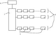
도 1은 제1 실시예에 따른 빌딩 환기 시스템의 정전 필터 용도의 본 발명에 따른 제어 전자 장치의 개략도를 도시하고 있다. 상기 정전 필터는 이온화 스테이지와 컬렉터 스테이지 그리고 상기 이온화 스테이지와 컬렉터 스테이지에 직류 고전압을 공급하기 위한 하나 또는 2개의 고전압 공급 유닛을 포함하고 있다. 상기 제어 전자 장치는 중앙 마스터 디바이스(1) 및 정전 필터 당 하나의 노드 디바이스(2)를 포함하고 있다. 노드 디바이스(2)는 바람직하게는 공구 없이도 체결할 수 있고 다시 분해가 가능한 기계적 수단에 의해 해당 정전 필터에 체결 가능하며 전기 접속이 가능하다. 상기 노드 디바이스는 해당 정전 필터에 전기 에너지를 공급하고 해당 정전 필터의 이온화 스테이지와 컬렉터 스테이지용 고전압 공급 유닛 또는 고전압 공급 유닛들을 제어한다. 마스터 디바이스(1)와 각각의 노드 디바이스(2)는 연산 유닛을 포함하고 있다. 상기 연산 유닛은 예를 들어 마이크로컨트롤러, 마이크로컴퓨터 등이다. 1 shows a schematic diagram of a control electronic device according to the invention for use of an electrostatic filter in a building ventilation system according to a first embodiment. The electrostatic filter includes an ionization stage and a collector stage and one or two high voltage supply units for supplying a direct current high voltage to the ionization stage and the collector stage. The control electronics comprises a
노드 디바이스(2)는 하나 이상의 체인(3)을 통해 마스터 디바이스(1)에 접속되어 있다. 각각의 체인(3)에서 제1 노드 디바이스(2)는 마스터 디바이스(1)에 접속 가능하고 다른 노드 디바이스(2)는 각각 전단의 노드 디바이스(2)에 접속 가능하여 동일한 체인(3)의 노드 디바이스들(2)이 직렬로 서로 연결되어 있다. 마스터 디바이스(1)는 체인(3)의 제1 노드 디바이스(2)의 전단 디바이스이다. 마스터 디바이스(1)와 노드 디바이스(2)는 커넥터가 구비된 연결 케이블을 통해 연결되어 있다. 상기 연결 케이블은 예를 들면 노드 디바이스(2)에 예를 들어 12 V의 제1 공급 전압을 공급하기 위한 2개의 라인, 정전 필터에 예를 들어 24 V의 제2 공급 전압 또는 예를 들어 230 V의 주전원 교류 전압을 공급하기 위한 2개의 다른 라인 및 데이터와 명령을 전송하기 위한 하나 이상의 데이터 라인을 포함하고 있다. 상기 12 V 및 24 V 라인들은 바람직하게는 서로 갈바닉 절연되어 있다. 상기 제1 공급 전압은 마스터 디바이스(1) 및 노드 디바이스(2)의 전자 장치에 전기 에너지를 공급하는 역할을 한다. 상기 제2 공급 전압은 정전 필터에 전기 에너지를 공급하는 역할을 한다. The
체인(3)의 노드 디바이스(2) 각각에는 고유한 위치 번호가 할당되어 있다. 노드 디바이스(2)는 공장에서 출하시에는 설정되어 있지 않는바, 즉 그의 위치 번호는 아직 결정되어 있지 않았거나 실제로 나오지 않을 높은 값으로 설정되어 있고, 빌딩 시스템 관련 데이터를 전혀 포함하고 있지 않다. 위치 번호의 할당은 노드 디바이스(2)를 빌딩 환기 시스템의 정전 필터 중 하나에 접속시키고 도 1에 도시되어 있는 개략도에 따라 마스터 디바이스(1)와 연결한 후에 자동으로 이루어지는바, 즉 작동자는 위치 번호를 지정할 필요가 없다.Each
상기 빌딩 환기 시스템의 정전 필터의 전자 제어 장치의 설정은 마스터 디바이스(1)의 연산 유닛이 설치되어 있는 마스터-설정 프로그램과 노드 디바이스(2)의 연산 유닛이 설치되어 있는 노드-설정 프로그램을 통해 이루어진다. The setting of the electronic control device of the electrostatic filter of the building ventilation system is made through a master setting program in which the computing unit of the
마스터 디바이스(1)의 연산 유닛은 마스터 설정 프로그램을 설정 모드로 실행하도록 구성되고 상기 마스터 설정 프로그램은 체인(3) 각각의 제1 노드 디바이스(2)의 연산 유닛이 노드 설정 프로그램을 실행하도록 하되, 상기 노드 설정 프로그램은 전단의 위치 번호를 수신하고 1씩 증가된 위치 번호를 노드 디바이스(2)에 할당하여 노드 디바이스(2)에 저장하도록 구성되고, 후속 노드 디바이스(2)의 접속 여부를 확인하고 접속되어 있는 경우에는 후속 노드 디바이스(2)의 연산 유닛이 상기 노드 설정 프로그램을 실행하게 한다.The calculating unit of the
후속 노드 디바이스(2)가 존재하지 않을 때, 체인(3)의 마지막 접속된 노드 디바이스(2)의 노드 설정 프로그램은 자신의 위치 번호를 그의 전단 노드 디바이스(2)에 전달하고 상기 전단 노드 디바이스는 다시 그의 전단 노드 디바이스(2)에 순차적으로 전달한다. 이러한 방법으로, 마스터 디바이스(1)는 체인(3) 각각으로부터 마지막 노드 디바이스(2)의 위치 번호를 수신하게 되면 체인(3) 각각의 노드 디바이스(2)의 갯수를 인식하게 된다. When no
상기 설정 방법에서 마스터 디바이스(1)는 체인(3)의 제1 노드 디바이스(2)의 전단으로서 취급된다. 따라서 마스터 디바이스(1)의 설정 프로그램은 체인(3)의 제1 노드 디바이스(2)에 위치 번호를 부여한 다음, 상기 위치 번호는 체인(3)의 제1 노드 디바이스(2)의 설정 프로그램에 의해 1씩 증가되도록 구성된다. 마스터 디바이스(1)에 의해 부여된 위치 번호는 예를 들어 모든 체인(3)에 대해 0의 값을 갖는다. 이 경우, 체인(3)의 노드 디바이스(2) 각각의 위치 번호는 체인(3) 내 노드 디바이스(2)의 위치에 상응하는 값을 갖는다. 즉, 체인(3)의 제1 노드 디바이스(2)는 위치 번호 1을 갖고, 체인(3)의 제2 노드 디바이스(2)는 위치 번호 2를 순차적으로 갖는다. 이러한 정전 필터의 노드 디바이스(2)에 위치 번호 할당은 도 1에서 노드 디바이스(2)의 우측 하단 모서리에 위치되어 있는 숫자에 의해 표시되어 있다.In the setting method, the
마스터 디바이스(1)의 위치 번호는 또한 체인(3) 각각에 대해 다른 위치 번호일 수 있는데, 예를 들어 제1 체인(3)에 대해서는 숫자 0일 수 있고, 후속 체인(3)에 대해서는 전단 체인(3)의 마지막 노드 디바이스(2)의 위치 번호일 수 있다. 이러한 방식으로 모든 체인(3)의 노드 디바이스(2)의 번호를 연속해서 표시할 수 있다.The position number of the
마스터 디바이스(1)와 노드 디바이스(2)는 노드 디바이스(2) 각각의 마스터 디바이스(1)가 그의 위치 번호와 그의 체인 번호(또는 그의 위치 번호만)에 의해 지정하게 하고 명령과 데이터를 이들과 교환할 수 있도록 하는 하나 이상의 다른 프로그램을 포함할 수 있다. The
상기 정전 필터는 여러 가지, 특히 1/1, 1/2 및 3/4 프레임 크기로 표시되는 3가지 크기로 제공된다. 상기 정전 필터는 프레임 크기와 필요한 경우에 추가 파라미터들에 대한 코딩부를 포함하고, 노드 디바이스(2)는 접속된 정전 필터의 코딩부를 결정하고 이로부터 프레임 크기와 경우에 따라 다른 파라미터들을 결정하기 위한 하나 이상의 센서를 포함하는 것이 유리하다. 상기 코딩부는 예를 들어 정전 필터에 소정 간격으로 서로 배치된 2개의 자석과 이에 따라 노드 디바이스(2)에 설치된 2개의 자계 센서에 의해 이루어진다. 상기 제1 자계 센서의 출력 신호는 제1 자석의 존재 여부를 나타낸다. 상기 제2 자계 센서의 출력 신호는 제2 자석의 존재 여부를 나타낸다. 하기 표는 가능한 코딩부를 보여준다.The electrostatic filter is provided in various sizes, in particular three sizes represented by 1/1, 1/2 and 3/4 frame sizes. The electrostatic filter comprises a coding section for the frame size and, if necessary, additional parameters, and the
상기 정전 필터의 이온화 스테이지의 제어는 바람직하게는 이온화 스테이지를 통해 흐를 이온화 전류를 미리 특정함으로써 이루어지고, 상기 정전 필터의 컬렉터 스테이지의 제어는 컬렉터 스테이지에 인가될 컬렉터 고전압을 미리 특정함으로써 이루어진다. 마스터 디바이스(1)는 바람직하게는 상위 빌딩 제어 디바이스(4)에 연결 가능하거나 빌딩 제어 디바이스의 일부에 연결 가능하고 상기 제어 전자 장치는 전체 빌딩 환기 시스템의 작동 상태에 따라 이온화 전류와 컬렉터 고전압을 제어하도록 구성되어 있다. 이에 대한 예로서: 상기 공기 체적 유량은 환풍기에 의해 0과 최대 공기 체적 유량 사이에서 조정될 수 있다. 이를 위해 빌딩 제어 유닛(4)은 마스터 디바이스(1)와 통신하고 바람직하게는 최대 공기 체적 유량의 퍼센트 또는 이에 상응하는 크기로 실제 공기 체적 유량에 해당하는 제어 신호를 마스터 디바이스에 전송한다. 마스터 디바이스(1)는 제어 신호 또는 이로부터 도출된 제어 신호를 노드 디바이스(2)에 전송하여 상기 제어 신호를 토대로 접속된 정전 필터의 작동 파라미터를 결정 및 조정 또는 조절하도록 구성되어 있다. 마스터 디바이스(1)는 특히 정전 필터가 배치되어 있는 환기관을 통해 흐르는 실제 공기 체적 유량을 나타내는 빌딩 제어 디바이스(4)로부터 수신된 제어 신호를 그로부터 유도되고 프레임 크기 1/1의 정전 필터를 통해 흐르는 실제 공기 체적 유량을 나타내는 제어 신호로 변환되도록 구성될 수 있다. 상기 작동 파라미터는 특히 이온화 전류와 컬렉터 고전압이다. 조정될 이온화 전류는 바람직하게는 실제 공기 체적 유량 뿐만 아니라 정전 필터의 프레임 크기에 따라 다르다. 따라서 노드 디바이스(2)는 전송된 제어 신호 및 검출된 코딩부로부터 결정된 접속된 정전 필터의 프레임 크기를 토대로 조정할 이온화 전류를 결정하고 전송된 제어 신호만을 토대로 조정할 컬렉터 고전압을 결정한다. 빌딩 제어 디바이스(4)와 마스터 디바이스(1)는 또한 다른 또는 추가 제어 명령을 전송하도록 구성될 수 있다.The control of the ionization stage of the electrostatic filter is preferably made by specifying in advance the ionization current that will flow through the ionization stage, and the control of the collector stage of the electrostatic filter is achieved by specifying in advance the collector high voltage to be applied to the collector stage. The
노드 디바이스(2)는 정전 필터의 프레임 크기와 경우에 따라서는 다른 결정된 파라미터를 해당 마스터 디바이스(1)에 전송하도록 구성될 수 있다. 이러한 전송은 예를 들어 설정 프로그램에 의해 설정 모드로 실행될 수 있다.The
노드 디바이스(2)는 상술한 바와 같이 소프트웨어에 의해 후속 노드 디바이스(2)의 접속 여부를 확인하도록 구성될 수 있다. 노드 디바이스(2)는 또한 이러한 과제를 지원하는 하드웨어 구성부를 구비할 수 있다. 이에 따라 노드 디바이스(2)의 입출력부에는 예를 들면 후속 노드 디바이스(2)가 접속되어 있지 않을 때 2개의 노드 디바이스(2) 사이에 존재하는 연결 케이블의 라인을 2진수값 "0"이 되게 하고 후속 노드 디바이스(2)가 접속되어 있을 때에는 2진수값 "1"이 되도록 제공되는 논리 소자가 포함될 수 있다.The
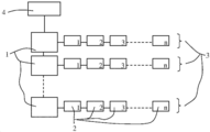
도 2는 제2 실시예에 따른 빌딩 환기 시스템의 정전 필터 용도의 본 발명에 따른 제어 전자 장치의 개략도를 도시하고 있다. 본 실시예에서는 각각의 체인(3)에 대해 별도의 마스터 디바이스(1)가 제공되어 있다. 마스터 디바이스(1) 각각에는 바람직하게는 별도의 전원부로부터 예들 들면 24 V의 제2 공급 전압이 공급된다. 이에 반해 예를 들면 12 V의 제1 공급 전압이 단일의 공통 전원부로부터 공급될 수 있다. 마스터 디바이스(1)는 버스(bus)를 통해 서로 연결되어 있다. 제1 마스터 디바이스(1)는 빌딩 제어 디바이스(4)에 접속 가능하게 구성되어 있다.2 shows a schematic diagram of a control electronic device according to the invention for use of an electrostatic filter in a building ventilation system according to a second embodiment. In this embodiment a
마스터 디바이스(1)는 설정 방법의 실행시 해당 체인(3)의 제1 노드 디바이스(2)의 전단으로서 취급된다. 체인(3) 각각의 노드 디바이스(2)에 위치 번호의 할당은 제1 실시예를 참고로 상술한 방법에 따라 이루어진다.The
마스터 디바이스(1)는 개별적으로, 그러나 공통 버스를 통해 빌딩 제어 디바이스(4)와 통신하거나 또는 빌딩 제어 디바이스(4)와 통신하는 주 마스터 디바이스(1)와 통신한다. 상기 주 마스터 디바이스는 제1 체인(3)의 마스터 디바이스(1)이거나 24 V 전원부(또는 230 V 전원부)가 없는 추가 마스터 디바이스일 수 있다.The
모든 실시예에서 24 V 전원부(또는 230 V 전원부)는 마스터 디바이스(1)에 통합되거나 별도의 구성 요소일 수 있다.In all embodiments the 24 V power supply (or 230 V power supply) may be integrated into the
도 3은 제3 실시예에 따른 빌딩 환기 시스템의 정전 필터 용도의 본 발명에 따른 제어 전자 장치의 개략도를 도시하고 있다. 이 실시예에는 여러 개의 마스터 디바이스(1)가 존재하고 각각의 마스터 디바이스(1)에는 노드 디바이스(2)의 하나 이상의 체인(3)이 접속 가능하다.3 shows a schematic diagram of a control electronic device according to the invention for use of an electrostatic filter in a building ventilation system according to a third embodiment. In this embodiment there are
모든 실시예에서 체인(3) 각각의 노드 디바이스(2)는 1부터 해당 체인의 노드 디바이스(2)의 수를 나타내는 n까지 숫자로 표시할 수 있거나 모든 체인(3)의 노드 디바이스(2)는 1부터 제어 전자 장치의 노드 디바이스(2)의 총 수를 나타내는 m까지 숫자로 표시할 수 있거나 동일한 마스터 디바이스(1)에 접속되어 있는 모든 체인(3)의 노드 디바이스(2)는 1부터 동일한 마스터 디바이스(1)에 접속된 노드 디바이스(2)의 총 수를 나타내는 k까지 숫자로 표시할 수 있다. In all embodiments the
본 발명은 각각의 노드 디바이스(2)와 이에 따라 정전 필터의 전체 어레이의 정전 필터 각각을 개별적으로 지정하고 파라미터화할 수 있다. 따라서 임의의 노드 디바이스(2) 또는 정전 필터에서 발생하는 에러는 적절한 제어 명령에 의해 국한될 수 있고 자동으로 극복될 수 있을 것이다. The invention can individually specify and parameterize each
노드 디바이스(2)는 해당 정전 필터에 제2 공급 전압(예를 들면 24 V DC 또는 230 V AC)을 공급한다. 상기 공급 전압은 갈바닉 절연부를 통해 전달되는 것이 바람직한바, 즉 노드 디바이스(2)와 해당 정전 필터는 PCT 출원 번호 PCT/EP2018/050093에 기재되어 있는 바와 같이 갈바닉 절연되는 것이 유리하다.The
본 발명의 실시형태들을 도시 및 기술하였지만, 본 발명의 개념을 벗어나지 않는 한 위에서 언급한 것보다 더 많은 변형들이 가능함은 당업자에게 자명할 것이다. 따라서 본 발명은 청구범위와 그의 균등범위에 의해서만 정의된다.While embodiments of the invention have been shown and described, it will be apparent to those skilled in the art that more variations are possible than those mentioned above without departing from the spirit of the invention. Accordingly, the invention is defined only by the claims and their equivalents.
Claims (5)
상기 정전 필터 각각에는 노드 디바이스(2)가 접속 가능하고,
마스터 디바이스(1) 또는 각각의 마스터 디바이스(1) 및 각각의 노드 디바이스(2)는 연산 유닛을 포함하고,
마스터 디바이스(1) 또는 각각의 마스터 디바이스(1)에는 노드 디바이스(2)의 하나 이상의 체인(3)이 접속 가능하되, 각각의 체인(3)에서 제1 노드 디바이스(2)가 해당 마스터 디바이스(1)에 접속 가능하고 체인(3)의 다른 노드 디바이스(2) 각각이 전단의 노드 디바이스(2)에 접속 가능하여 체인(3)의 노드 디바이스(2)가 서로 직렬로 연결되며, 마스터 디바이스(1)가 접속된 체인(3)의 제1 노드 디바이스(2)의 전단 디바이스이거나 접속된 체인들(3)의 제1 노드 디바이스들(2)의 전단 디바이스이고,
체인(3)의 노드 디바이스(2) 각각에는 위치 번호가 할당되고,
마스터 디바이스(1) 또는 마스터 디바이스들(1)의 연산 유닛은 접속된 체인(3) 각각의 제1 노드 디바이스(2)의 연산 유닛이 전단의 위치 번호를 수신하고 자동으로 1씩 증가된 위치 번호를 할당하여 노드 디바이스(2)에 저장하도록 구성된 설정 프로그램을 설정 모드로 실행하고, 후속 노드 디바이스(2)의 접속 여부를 확인하고 접속되어 있는 경우에는 후속 노드 디바이스(2)의 연산 유닛이 상기 설정 프로그램을 실행하게 하도록 구성된 제어 전자 장치.A control electronics for a plurality of electrostatic filters of a building ventilation system comprising at least one master device (1) and node devices (2),
The node device 2 can be connected to each of the electrostatic filters,
The master device 1 or each master device 1 and each node device 2 comprises a computing unit,
One or more chains 3 of node devices 2 are connectable to the master device 1 or to each master device 1, in which the first node device 2 is connected to the master device ( 1) and each of the other node devices 2 of the chain 3 can be connected to the node device 2 of the front end so that the node devices 2 of the chain 3 are connected in series with each other, and the master device ( 1) is the front end device of the first node device 2 of the connected chain 3 or the front end device of the first node devices 2 of the connected chain 3,
Each node device 2 of the chain 3 is assigned a location number,
The calculation unit of the master device 1 or the master devices 1 receives the position number of the front end of the operation unit of the first node device 2 of each of the connected chains 3 and automatically increases the position number by one. Is executed in the setting mode configured to allocate and store in the node device 2, and confirms whether or not the subsequent node device 2 is connected and, if connected, the arithmetic unit of the subsequent node device 2 sets the above setting. Control electronics configured to execute a program.
적어도 하나의 마스터 디바이스(1)가 빌딩 제어 디바이스(4)와 연결 가능하거나 빌딩 제어 디바이스(4)의 일부에 연결 가능하고,
적어도 하나의 마스터 디바이스(1)가 빌딩 제어 디바이스(4)로부터 전송된 제어 신호 또는 그로부터 유도된 제어 신호를 노드 디바이스(2)에 전송하도록 구성되고,
노드 디바이스(2) 각각이 전송된 제어 신호와 경우에 따라 접속된 정전 필터의 프레임 크기를 토대로 해당 정전 필터에 대해 조정할 이온화 전류를 결정하고/또는 전송된 제어 신호를 토대로 컬렉터에 인가할 직류 고전압을 결정하도록 구성되는 것을 특징으로 하는 제어 전자 장치.4. The collector according to any one of claims 1 to 3, wherein each of said electrostatic filters has a predetermined frame size and comprises an ionization stage and a collector stage, wherein control of each of said electrostatic filters is an ionization current and a collector flowing through the ionization stage. Is performed by setting the DC high voltage to be applied to the stage,
At least one master device 1 is connectable with the building control device 4 or with a part of the building control device 4,
At least one master device 1 is configured to transmit a control signal transmitted from the building control device 4 or a control signal derived therefrom to the node device 2,
Each of the node devices 2 determines the ionization current to be adjusted for the electrostatic filter based on the transmitted control signal and optionally the frame size of the connected electrostatic filter and / or direct current high voltage to be applied to the collector based on the transmitted control signal. And control the electronic device.
Applications Claiming Priority (3)
| Application Number | Priority Date | Filing Date | Title |
|---|---|---|---|
| CH00096/17 | 2017-01-30 | ||
| CH00096/17A CH713392A1 (en) | 2017-01-30 | 2017-01-30 | Control electronics for several electrostatic filters. |
| PCT/EP2018/052090 WO2018138315A1 (en) | 2017-01-30 | 2018-01-29 | Control electronics for multiple electric filters |
Publications (1)
| Publication Number | Publication Date |
|---|---|
| KR20190109425A true KR20190109425A (en) | 2019-09-25 |
Family
ID=61094519
Family Applications (1)
| Application Number | Title | Priority Date | Filing Date |
|---|---|---|---|
| KR1020197022228A KR20190109425A (en) | 2017-01-30 | 2018-01-29 | Control electronics for many electrostatic filters |
Country Status (13)
| Country | Link |
|---|---|
| US (1) | US11079133B2 (en) |
| EP (1) | EP3555712B1 (en) |
| JP (1) | JP7103666B2 (en) |
| KR (1) | KR20190109425A (en) |
| CN (1) | CN110235067B (en) |
| AU (1) | AU2018212601B2 (en) |
| BR (1) | BR112019015685A2 (en) |
| CA (1) | CA3051633C (en) |
| CH (1) | CH713392A1 (en) |
| DK (1) | DK3555712T3 (en) |
| RU (1) | RU2752102C2 (en) |
| SG (1) | SG11201906651XA (en) |
| WO (1) | WO2018138315A1 (en) |
Families Citing this family (5)
| Publication number | Priority date | Publication date | Assignee | Title |
|---|---|---|---|---|
| US11287429B2 (en) | 2018-09-25 | 2022-03-29 | Siemens Healthcare Diagnostics Inc. | Compositions, kits, and methods for multiplex assays to correct for biotin interference in target analyte measurements |
| CN109812944B (en) * | 2019-03-20 | 2023-12-01 | 杭州地铁运营有限公司 | Air valve control circuit board of ventilation air conditioning system |
| CN112113292A (en) * | 2020-10-13 | 2020-12-22 | 山东新华医疗器械股份有限公司 | Medical air disinfection purifier with double working modes |
| US20230375208A1 (en) * | 2020-10-23 | 2023-11-23 | Zehnder Group International Ag | Method of operating an air cleaning cluster |
| CN112628935A (en) * | 2020-12-22 | 2021-04-09 | 丽水市知源科技有限公司 | Market air conditioning system based on Internet of things and control method thereof |
Family Cites Families (29)
| Publication number | Priority date | Publication date | Assignee | Title |
|---|---|---|---|---|
| JPS57119857A (en) * | 1981-01-19 | 1982-07-26 | Takuma Co Ltd | Control method for electrostatic precipitator |
| JPH08328618A (en) * | 1995-05-31 | 1996-12-13 | Showa Tekko Kk | Address setting device of terminal equipment |
| US5578112A (en) * | 1995-06-01 | 1996-11-26 | 999520 Ontario Limited | Modular and low power ionizer |
| WO2000002345A2 (en) * | 1998-07-02 | 2000-01-13 | Amino Holdings Limited | Electronic system architecture |
| ES2200367T3 (en) * | 1998-09-18 | 2004-03-01 | F.L. Smidth Airtech A/S | A METHOD OF OPERATION OF AN ELECTROSTATIC PRECIPITATOR. |
| US6576046B2 (en) * | 2000-10-19 | 2003-06-10 | Fedders Corporation | Modular electrostatic precipitator system |
| JP2004077018A (en) * | 2002-08-19 | 2004-03-11 | Fujitsu General Ltd | Air-conditioner network system |
| DE10261174B3 (en) * | 2002-12-20 | 2004-06-17 | Daimlerchrysler Ag | Automatic addressing method for control devices connected to data bus system with series or ring structure |
| DE102004036210B4 (en) * | 2004-07-26 | 2006-08-31 | Siemens Ag | Control device and control method for electrostatic precipitators with a configurable number of parallel and serial filter zones |
| JP3979436B1 (en) * | 2006-03-09 | 2007-09-19 | ダイキン工業株式会社 | Air conditioner and address setting method in air conditioner |
| US8400061B2 (en) * | 2007-07-17 | 2013-03-19 | I/O Controls Corporation | Control network for LED-based lighting system in a transit vehicle |
| US8397527B2 (en) * | 2007-07-30 | 2013-03-19 | Jack V. Miller | Energy saving integrated lighting and HVAC system |
| EP2031568A1 (en) * | 2007-08-28 | 2009-03-04 | CC Trust Group AG | Selling device and method for operating such selling machine and product for such a selling machine |
| US8291380B2 (en) * | 2008-03-05 | 2012-10-16 | International Business Machines Corporation | Methods for configuring software package |
| AU2009290588B2 (en) * | 2008-09-15 | 2015-11-26 | Haier Us Appliance Solutions, Inc. | Energy management of household appliances |
| US8296488B2 (en) * | 2009-04-27 | 2012-10-23 | Abl Ip Holding Llc | Automatic self-addressing method for wired network nodes |
| WO2012075038A1 (en) | 2010-12-01 | 2012-06-07 | Michael Gordon | Vending modified climate control device |
| US20140076291A1 (en) * | 2011-08-09 | 2014-03-20 | Clean Air Power, Inc | Method and apparatus for controlling premixed combustion in a multimode engine |
| US8922971B2 (en) * | 2012-01-13 | 2014-12-30 | Clean Air Group, Inc. | Integrated bi-polar ionization air purification for fan-powered air distribution devices |
| EP2841740B1 (en) * | 2012-04-26 | 2020-04-01 | General Electric Company | System and method of recirculating exhaust gas for use in a plurality of flow paths in a gas turbine engine |
| US20140022941A1 (en) * | 2012-07-17 | 2014-01-23 | The Procter & Gamble Company | Systems and methods for networking consumer devices |
| US20140173081A1 (en) * | 2012-11-13 | 2014-06-19 | Joshua P. Knapp | Method and apparatus for discovery and enumeration of sequentially networked devices |
| US20140223048A1 (en) * | 2013-02-06 | 2014-08-07 | Infineon Technologies Ag | Communication network and method for communicating in a communication network |
| BR112015019014A2 (en) * | 2013-02-07 | 2017-07-18 | Honeywell Int Inc | building control system for controlling one or more building components servicing a building, and method of controlling one or more separate air conditioning units servicing a building |
| DE112013006713T5 (en) * | 2013-02-21 | 2015-11-12 | Mitsubishi Electric Corporation | Networked air conditioning, repeaters and program |
| US9737842B2 (en) * | 2014-04-25 | 2017-08-22 | Fellowes, Inc. | Air purifier with intelligent sensors and airflow |
| CN204496182U (en) * | 2015-04-03 | 2015-07-22 | 周颖 | Based on the Smart Home ventilating system of Internet of Things |
| US10215430B2 (en) * | 2015-06-15 | 2019-02-26 | Lunatech, Llc | Electronic vapor and analysis with HVAC integration |
| CN106354041B (en) * | 2016-10-24 | 2018-08-28 | 上海革创电子科技有限公司 | A kind of tandem type multinode industrial automation control system of non-all-key parallel bus |
-
2017
- 2017-01-30 CH CH00096/17A patent/CH713392A1/en not_active Application Discontinuation
-
2018
- 2018-01-29 DK DK18702257.9T patent/DK3555712T3/en active
- 2018-01-29 RU RU2019122140A patent/RU2752102C2/en active
- 2018-01-29 JP JP2019528056A patent/JP7103666B2/en active Active
- 2018-01-29 CA CA3051633A patent/CA3051633C/en active Active
- 2018-01-29 AU AU2018212601A patent/AU2018212601B2/en active Active
- 2018-01-29 CN CN201880008985.9A patent/CN110235067B/en active Active
- 2018-01-29 SG SG11201906651XA patent/SG11201906651XA/en unknown
- 2018-01-29 BR BR112019015685A patent/BR112019015685A2/en unknown
- 2018-01-29 EP EP18702257.9A patent/EP3555712B1/en active Active
- 2018-01-29 KR KR1020197022228A patent/KR20190109425A/en not_active IP Right Cessation
- 2018-01-29 WO PCT/EP2018/052090 patent/WO2018138315A1/en unknown
- 2018-01-29 US US16/476,067 patent/US11079133B2/en active Active
Also Published As
| Publication number | Publication date |
|---|---|
| JP2020509442A (en) | 2020-03-26 |
| AU2018212601A1 (en) | 2019-07-25 |
| EP3555712B1 (en) | 2020-04-08 |
| SG11201906651XA (en) | 2019-08-27 |
| JP7103666B2 (en) | 2022-07-20 |
| RU2019122140A3 (en) | 2021-05-18 |
| US20200003445A1 (en) | 2020-01-02 |
| CN110235067B (en) | 2022-04-26 |
| CN110235067A (en) | 2019-09-13 |
| BR112019015685A2 (en) | 2020-04-07 |
| EP3555712A1 (en) | 2019-10-23 |
| CH713392A1 (en) | 2018-07-31 |
| CA3051633A1 (en) | 2018-08-02 |
| WO2018138315A1 (en) | 2018-08-02 |
| US11079133B2 (en) | 2021-08-03 |
| CA3051633C (en) | 2023-06-13 |
| DK3555712T3 (en) | 2020-05-18 |
| AU2018212601B2 (en) | 2021-10-21 |
| RU2019122140A (en) | 2021-03-01 |
| RU2752102C2 (en) | 2021-07-22 |
Similar Documents
| Publication | Publication Date | Title |
|---|---|---|
| KR20190109425A (en) | Control electronics for many electrostatic filters | |
| KR920020150A (en) | Current controller of air conditioner system | |
| US10378785B2 (en) | Communication system and communication apparatus | |
| CN102692328A (en) | System and method for detecting multi-split air conditioner | |
| JP2020509442A5 (en) | ||
| KR20160039680A (en) | Smart power system | |
| CN103837821B (en) | The communication detecting method of a kind of current-loop communication circuit and system | |
| EP2627013A1 (en) | Power line communication apparatus and method, and load power monitoring apparatus and method using same | |
| KR20180105830A (en) | A method of automatically setting the communication terminal resistance of an energy storage device(ESS) | |
| EP2237484B1 (en) | Building equipment system and control method thereof | |
| EP3157155A1 (en) | Method of controlling inverters | |
| US10127173B2 (en) | Connection device | |
| CN103901858A (en) | Electric actuator control system and method based on internal bus | |
| CN104502782A (en) | Circuit detecting system for household distribution box | |
| KR101990399B1 (en) | Building automation system, gateway comprised therein and method of operating the gateway | |
| CN104391556A (en) | Power supply protection device and method | |
| CN203838545U (en) | Electric performer control system based on internal bus | |
| CN112379611B (en) | Environment monitoring control equipment | |
| EP3965399B1 (en) | Electronic device and hardware address configuration method | |
| KR20100089655A (en) | Building equipment system | |
| US20220035349A1 (en) | Controllers of a vacuum pumping and/or abatement system | |
| JP6576310B2 (en) | VAV controller | |
| KR101673576B1 (en) | Smart building control system and method thereof | |
| CN105409133A (en) | Antenna cascade relationship recognition method, antenna device and antenna control device | |
| KR101610030B1 (en) | Wire/wireless integrated controller and control system capable of saving building energy |
Legal Events
| Date | Code | Title | Description |
|---|---|---|---|
| A201 | Request for examination | ||
| E902 | Notification of reason for refusal | ||
| AMND | Amendment | ||
| E90F | Notification of reason for final refusal | ||
| E601 | Decision to refuse application | ||
| AMND | Amendment | ||
| X601 | Decision of rejection after re-examination |