CN110235067B - Control electronics for multiple electronic filters - Google Patents
Control electronics for multiple electronic filters Download PDFInfo
- Publication number
- CN110235067B CN110235067B CN201880008985.9A CN201880008985A CN110235067B CN 110235067 B CN110235067 B CN 110235067B CN 201880008985 A CN201880008985 A CN 201880008985A CN 110235067 B CN110235067 B CN 110235067B
- Authority
- CN
- China
- Prior art keywords
- node
- control
- node device
- master
- chain
- Prior art date
- Legal status (The legal status is an assumption and is not a legal conclusion. Google has not performed a legal analysis and makes no representation as to the accuracy of the status listed.)
- Active
Links
Images

Classifications
-
- G—PHYSICS
- G06—COMPUTING; CALCULATING OR COUNTING
- G06F—ELECTRIC DIGITAL DATA PROCESSING
- G06F13/00—Interconnection of, or transfer of information or other signals between, memories, input/output devices or central processing units
- G06F13/10—Program control for peripheral devices
-
- G—PHYSICS
- G05—CONTROLLING; REGULATING
- G05B—CONTROL OR REGULATING SYSTEMS IN GENERAL; FUNCTIONAL ELEMENTS OF SUCH SYSTEMS; MONITORING OR TESTING ARRANGEMENTS FOR SUCH SYSTEMS OR ELEMENTS
- G05B15/00—Systems controlled by a computer
- G05B15/02—Systems controlled by a computer electric
-
- F—MECHANICAL ENGINEERING; LIGHTING; HEATING; WEAPONS; BLASTING
- F24—HEATING; RANGES; VENTILATING
- F24F—AIR-CONDITIONING; AIR-HUMIDIFICATION; VENTILATION; USE OF AIR CURRENTS FOR SCREENING
- F24F11/00—Control or safety arrangements
- F24F11/0001—Control or safety arrangements for ventilation
-
- F—MECHANICAL ENGINEERING; LIGHTING; HEATING; WEAPONS; BLASTING
- F24—HEATING; RANGES; VENTILATING
- F24F—AIR-CONDITIONING; AIR-HUMIDIFICATION; VENTILATION; USE OF AIR CURRENTS FOR SCREENING
- F24F11/00—Control or safety arrangements
- F24F11/30—Control or safety arrangements for purposes related to the operation of the system, e.g. for safety or monitoring
- F24F11/49—Control or safety arrangements for purposes related to the operation of the system, e.g. for safety or monitoring ensuring correct operation, e.g. by trial operation or configuration checks
-
- F—MECHANICAL ENGINEERING; LIGHTING; HEATING; WEAPONS; BLASTING
- F24—HEATING; RANGES; VENTILATING
- F24F—AIR-CONDITIONING; AIR-HUMIDIFICATION; VENTILATION; USE OF AIR CURRENTS FOR SCREENING
- F24F11/00—Control or safety arrangements
- F24F11/50—Control or safety arrangements characterised by user interfaces or communication
- F24F11/54—Control or safety arrangements characterised by user interfaces or communication using one central controller connected to several sub-controllers
-
- F—MECHANICAL ENGINEERING; LIGHTING; HEATING; WEAPONS; BLASTING
- F24—HEATING; RANGES; VENTILATING
- F24F—AIR-CONDITIONING; AIR-HUMIDIFICATION; VENTILATION; USE OF AIR CURRENTS FOR SCREENING
- F24F11/00—Control or safety arrangements
- F24F11/62—Control or safety arrangements characterised by the type of control or by internal processing, e.g. using fuzzy logic, adaptive control or estimation of values
- F24F11/63—Electronic processing
- F24F11/65—Electronic processing for selecting an operating mode
-
- F—MECHANICAL ENGINEERING; LIGHTING; HEATING; WEAPONS; BLASTING
- F24—HEATING; RANGES; VENTILATING
- F24F—AIR-CONDITIONING; AIR-HUMIDIFICATION; VENTILATION; USE OF AIR CURRENTS FOR SCREENING
- F24F11/00—Control or safety arrangements
- F24F11/88—Electrical aspects, e.g. circuits
-
- F—MECHANICAL ENGINEERING; LIGHTING; HEATING; WEAPONS; BLASTING
- F24—HEATING; RANGES; VENTILATING
- F24F—AIR-CONDITIONING; AIR-HUMIDIFICATION; VENTILATION; USE OF AIR CURRENTS FOR SCREENING
- F24F8/00—Treatment, e.g. purification, of air supplied to human living or working spaces otherwise than by heating, cooling, humidifying or drying
- F24F8/10—Treatment, e.g. purification, of air supplied to human living or working spaces otherwise than by heating, cooling, humidifying or drying by separation, e.g. by filtering
- F24F8/192—Treatment, e.g. purification, of air supplied to human living or working spaces otherwise than by heating, cooling, humidifying or drying by separation, e.g. by filtering by electrical means, e.g. by applying electrostatic fields or high voltages
-
- G—PHYSICS
- G05—CONTROLLING; REGULATING
- G05B—CONTROL OR REGULATING SYSTEMS IN GENERAL; FUNCTIONAL ELEMENTS OF SUCH SYSTEMS; MONITORING OR TESTING ARRANGEMENTS FOR SUCH SYSTEMS OR ELEMENTS
- G05B19/00—Programme-control systems
- G05B19/02—Programme-control systems electric
-
- G—PHYSICS
- G05—CONTROLLING; REGULATING
- G05B—CONTROL OR REGULATING SYSTEMS IN GENERAL; FUNCTIONAL ELEMENTS OF SUCH SYSTEMS; MONITORING OR TESTING ARRANGEMENTS FOR SUCH SYSTEMS OR ELEMENTS
- G05B19/00—Programme-control systems
- G05B19/02—Programme-control systems electric
- G05B19/04—Programme control other than numerical control, i.e. in sequence controllers or logic controllers
- G05B19/042—Programme control other than numerical control, i.e. in sequence controllers or logic controllers using digital processors
-
- G—PHYSICS
- G05—CONTROLLING; REGULATING
- G05B—CONTROL OR REGULATING SYSTEMS IN GENERAL; FUNCTIONAL ELEMENTS OF SUCH SYSTEMS; MONITORING OR TESTING ARRANGEMENTS FOR SUCH SYSTEMS OR ELEMENTS
- G05B9/00—Safety arrangements
- G05B9/02—Safety arrangements electric
- G05B9/03—Safety arrangements electric with multiple-channel loop, i.e. redundant control systems
-
- B—PERFORMING OPERATIONS; TRANSPORTING
- B03—SEPARATION OF SOLID MATERIALS USING LIQUIDS OR USING PNEUMATIC TABLES OR JIGS; MAGNETIC OR ELECTROSTATIC SEPARATION OF SOLID MATERIALS FROM SOLID MATERIALS OR FLUIDS; SEPARATION BY HIGH-VOLTAGE ELECTRIC FIELDS
- B03C—MAGNETIC OR ELECTROSTATIC SEPARATION OF SOLID MATERIALS FROM SOLID MATERIALS OR FLUIDS; SEPARATION BY HIGH-VOLTAGE ELECTRIC FIELDS
- B03C2201/00—Details of magnetic or electrostatic separation
- B03C2201/32—Checking the quality of the result or the well-functioning of the device
-
- B—PERFORMING OPERATIONS; TRANSPORTING
- B03—SEPARATION OF SOLID MATERIALS USING LIQUIDS OR USING PNEUMATIC TABLES OR JIGS; MAGNETIC OR ELECTROSTATIC SEPARATION OF SOLID MATERIALS FROM SOLID MATERIALS OR FLUIDS; SEPARATION BY HIGH-VOLTAGE ELECTRIC FIELDS
- B03C—MAGNETIC OR ELECTROSTATIC SEPARATION OF SOLID MATERIALS FROM SOLID MATERIALS OR FLUIDS; SEPARATION BY HIGH-VOLTAGE ELECTRIC FIELDS
- B03C3/00—Separating dispersed particles from gases or vapour, e.g. air, by electrostatic effect
- B03C3/34—Constructional details or accessories or operation thereof
- B03C3/66—Applications of electricity supply techniques
- B03C3/68—Control systems therefor
-
- F—MECHANICAL ENGINEERING; LIGHTING; HEATING; WEAPONS; BLASTING
- F24—HEATING; RANGES; VENTILATING
- F24F—AIR-CONDITIONING; AIR-HUMIDIFICATION; VENTILATION; USE OF AIR CURRENTS FOR SCREENING
- F24F2110/00—Control inputs relating to air properties
- F24F2110/50—Air quality properties
- F24F2110/64—Airborne particle content
-
- F—MECHANICAL ENGINEERING; LIGHTING; HEATING; WEAPONS; BLASTING
- F24—HEATING; RANGES; VENTILATING
- F24F—AIR-CONDITIONING; AIR-HUMIDIFICATION; VENTILATION; USE OF AIR CURRENTS FOR SCREENING
- F24F2203/00—Devices or apparatus used for air treatment
-
- G—PHYSICS
- G05—CONTROLLING; REGULATING
- G05B—CONTROL OR REGULATING SYSTEMS IN GENERAL; FUNCTIONAL ELEMENTS OF SUCH SYSTEMS; MONITORING OR TESTING ARRANGEMENTS FOR SUCH SYSTEMS OR ELEMENTS
- G05B2219/00—Program-control systems
- G05B2219/20—Pc systems
- G05B2219/26—Pc applications
- G05B2219/2614—HVAC, heating, ventillation, climate control
Landscapes
- Engineering & Computer Science (AREA)
- General Engineering & Computer Science (AREA)
- Combustion & Propulsion (AREA)
- Mechanical Engineering (AREA)
- Chemical & Material Sciences (AREA)
- Physics & Mathematics (AREA)
- Automation & Control Theory (AREA)
- General Physics & Mathematics (AREA)
- Signal Processing (AREA)
- Human Computer Interaction (AREA)
- Mathematical Physics (AREA)
- Fuzzy Systems (AREA)
- Theoretical Computer Science (AREA)
- Electrostatic Separation (AREA)
- Ventilation (AREA)
- Programmable Controllers (AREA)
Abstract
The invention relates to control electronics for a plurality of electronic filters of a ventilation installation of a building, comprising: at least one master device (1) and a node device (2), wherein a node device (2) can be connected to each electronic filter. One or more chains (3) of node devices (2) can be connected to the master device (1) or to each master device (1), wherein in each chain (3) a first node device (2) can be connected to the associated master device (1) and the other node devices (2) of the chain (3) can be connected to the respective preceding node device (2) in such a way that the node devices (2) of the chain (3) are connected to one another in series, wherein the master device (1) is the former of the connected chain (3) or of the one or more first node devices (2) of the connected chains (3). At least one master device (1) and a node device (2) are designed to number the one-to-one position associated with each node device (2) of a chain (3). The transmission of the supply voltage from the node device (2) to the connected electronic filter can take place via the galvanic isolation element.
Description
Technical Field
The invention relates to control electronics for an electronic filter of a building ventilation installation of a larger building. Such building ventilation systems are also referred to as unit assemblies in the air conditioning and ventilation industry
Background
Electronic filters are capable of filtering out particles contained in a gas or air stream. Although the electronic filter can be used in ventilation systems, in air conditioning systems and in air conditioning systems, it is not widespread in the ventilation industry. Bag filters are still used in the ventilation industry, particularly in building ventilation installations. In the modular units, depending on the size of the building, different numbers of bag filters are arranged side by side and one above the other. If the bag filter is replaced by an electronic filter of the same construction size, control electronics are required which are capable of controlling a plurality of electronic filters.
Disclosure of Invention
The invention is based on the object of developing a control electronics for a plurality of electronic filters, which control electronics, in addition to fulfilling its main task, namely controlling the electronic filters, also enables simple installation and maintenance together with simple replacement and replacement of defective parts.
The object mentioned is achieved according to the invention by a control electronics for a plurality of electronic filters of a ventilation installation of a building. Advantageous embodiments are described in the following description.
The invention relates to control electronics for a plurality of electronic filters which are arranged in a ventilation duct of a ventilation system of a building. The control electronics comprise at least one master device and a node device, wherein a node device can be connected to each of the electronic filters. The master device or the master devices are the upper-level control center for the electronic filter and furthermore supply the connected node devices with the supply voltage for the electronic filter.
The preferred embodiment of the master device and the node device comprises the following features, which can be implemented individually or in combination, namely:
1. the or each master device and each node device has a computing unit and the devices are configured as follows: one or more chains of node devices can be connected to the master device or to each of the master devices, wherein in each chain a first node device can be connected to the master device to which it belongs and the other node devices of the chain can be connected to the preceding node device in each case, so that the node devices of the chain are connected to one another in series. Here, the master device is the former of the first node devices of one chain connected thereto or the former of the first node devices of a plurality of chains connected thereto. Each of the node devices of a chain is associated with a one-to-one location number. The computing units of the one or more master devices are designed to, in a configuration mode, facilitate the computing units of the first node devices of each connected chain to execute a configuration program designed to:
receiving a location number of its former and assigning itself a location number incremented by a value of 1 and storing in the node device;
it is determined whether a subsequent node device is connected and, if so, the computing unit of the subsequent node device is urged to execute the configuration program.
2. The electronic filter can contain a code, which is formed, for example, by a permanent magnet. For determining the code, the node device advantageously has one or more sensors, and the configuration program is additionally designed to determine the code of the connected electronic filter from the output signal of one sensor or from the output signals of a plurality of sensors.
3. Each of the node devices has a galvanic isolation element for transferring a supply voltage of the node device to the connected electronic filter. This can be achieved: the ionization and collector stages of the electronic filter are controlled according to the principles described in PCT application No. PCT/EP 2018/050093.
The control electronics are furthermore preferably designed to control electronic filters of different structural sizes, wherein each of the electronic filters has a predetermined structural size and comprises an ionization stage and a collector stage. The control of each of the electronic filters is achieved in particular by presetting the ionization current flowing through the ionization stage and the dc high voltage to be applied to the collector stage, wherein the ionization current is adapted in particular to the air volume flow flowing through the ventilation channel and to the structural size of the electronic filter. The dc high voltage applied to the collector stage is also advantageously matched to the air volume flow.
The or each main device can be connectable to a building control device, wherein the building control device transmits a control signal to the or each main device, the control signal being a magnitude of the volumetric flow of air through the ventilation facility. One or more master devices can also be part of the building control device. The one or more master devices are designed to transmit control signals transmitted from the building control device or control signals derived from said control signals to the node devices. The node device is advantageously designed to determine the ionization current and/or the dc high voltage as a function of the at least one control signal and optionally further parameters, for example the structural size of the electronic filter, and to transmit it to the connected electronic filter.
Drawings
The invention is explained in detail below on the basis of embodiments and on the basis of the drawings.
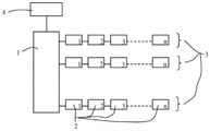
Fig. 1 to 3 show a respective schematic diagram of the control electronics according to the invention for an electronic filter of a ventilation system of a building.
Detailed Description
Fig. 1 shows a schematic view of the control electronics according to the invention for an electronic filter for a building ventilation installation according to a first embodiment. The electronic filter includes an ionization stage and a collector stage and one or two high voltage feeds for supplying a dc high voltage to the ionization stage and the collector stage. The control electronics comprise a central main device 1 and one node device 2 for each electronic filter. The node device 2 can preferably be fastened and electrically connected to the associated electronic filter by means of a mechanical mechanism that can be fastened without tools and can be released again. The node device supplies electrical energy to the associated electronic filter and controls one or more high-voltage power supply devices for the ionization and collector stages of the associated electronic filter. The master device 1 and each node device 2 have a calculation unit. The computing unit is, for example, a microcontroller, a microcomputer or the like.
The node devices 2 are connected to the master device 1 via one or more chains 3. In each chain 3, a first node device 2 may be connected to the master device 1 and the other node devices 2 may be connected to the previous node device 2, respectively, such that the node devices 2 of the same chain 3 are connected to each other in series. The master 1 is the former of the first node device 2 of a chain 3. The main device 1 and the node device 2 are connected via a connection cable equipped with a plug. The connection cable includes, for example: two wires for supplying the node device 2 with a first supply voltage of, for example, 12V; two further lines for supplying the electronic filter with a second supply voltage of, for example, 24V or with a mains ac voltage of, for example, 230V; and one or more data lines for transmitting data and instructions. The 12V and 24V wires are preferably galvanically isolated from each other. The first supply voltage is used to supply the electronics of the master device 1 and the node device 2 with electrical energy. The second supply voltage is used to power the electronic filter.
Each of the node devices 2 of one chain 3 is associated with a one-to-one location number. The node device 2 is unconfigured when it leaves the factory, i.e. its position number is either not yet determined or specified to a high value, which in practice does not occur, and which also never contains data about the building facilities. The association of the location numbers takes place automatically after the node device 2 has been connected to one of the electronic filters of the building ventilation system and to the main device 1 according to the diagram shown in fig. 1, i.e. the operator does not have to assign a location number.
The configuration of the control electronics of the electronic filter of the building ventilation installation takes place by means of a main configuration program installed on the computing unit of the main device 1 and a node configuration program installed on the computing unit of the node device 2.
The computing unit of the master device 1 is designed to execute, in a configuration mode, a master configuration program that facilitates the computing unit of the first node device 2 of each chain 3 to execute a node configuration program, wherein the node configuration program is designed to:
receiving the position number of the former thereof and assigning the position number increased by the value 1 to the node apparatus 2 and storing in the node apparatus 2;
it is determined whether the subsequent node apparatus 2 is connected, and if this is the case, the calculation unit of the subsequent node apparatus 2 is pushed to execute the node configuration program.
If no subsequent node device 2 is present, the node configuration program of the last connected node device 2 of a chain 3 transmits its position number to its previous node device 2 and transmits the position number again to its previous node device 2, and so on. In this way, the master device 1 obtains the position number of the last node device 2 of each chain in the chain 3, thereby knowing the number of node devices 2 of each chain 3.
The master device 1 is treated in the configuration method as the former of the first node device 2 of a chain 3. The configuration program of the master device 1 is therefore designed to transmit a position number to the first node device 2 of a chain 3, which is then incremented by the value 1 by the configuration program of the first node device 2 of the chain 3. The position number transmitted by the master 1 has, for example, a value of 0 for all chains 3. The position number of each node device 2 of a chain 3 then has a value corresponding to the position of the node device 2 in the chain 3. That is, the first node device 2 of one chain 3 has a location number 1, the second node device 2 of one chain 3 has a location number 2, and so on. This association of the location number with the node device 2 of the electronic filter is shown in fig. 1 by a number, which is arranged in the lower right corner of the node device 2.
However, the position number of the master 1 can also be a further position number for each of the chains 3, for example a number 0 for the first chain 3 and a position number of the last node device 2 of the previous chain 3 for the following chain 3. In this way it is possible to number the node devices 2 of all chains 3 consecutively.
The master device 1 and the node devices 2 contain one or more further programs by means of which the master device 1 activates (ansprechen) each node device 2 via the position number of the node device 2 or its chain number (or its unique position number) and can exchange instructions and data with the node device.
Electronic filters are provided in a variety of, particularly three, structural sizes, referred to as 1/1, 1/2, and 3/4 structural sizes. The electronic filter advantageously contains a code for the structure size and in any case other parameters, and the node device 2 contains one or more sensors in order to determine the code of the connected electronic filter and from it the structure size and possibly other parameters. The coding takes place, for example, by means of two magnets arranged at a distance from one another at the electronic filter and two magnetic field sensors which are correspondingly arranged on the node device 2. The output signal of the first magnetic field sensor states: whether the first magnet is present. The output signal of the second magnetic field sensor states: whether a second magnet is present. The following table shows possible encodings:
| magnet 1 | |
Encoding |
| Is absent from | Is absent from | Without electronic filter |
| Exist of | Is absent from | 1/1 electronic filter |
| Is absent from | Exist of | 1/2 electronic filter |
| Exist of | Exist of | 3/4 electronic filter |
The control of the ionization level of the electronic filter is preferably effected by presetting the ionization current, which should flow through the ionization level, and the control of the collector level of the electronic filter by presetting the collector high voltage, which should be applied to the collector level. The main device 1 is preferably connectable to a superordinate building control device 4 or is part of a building control device, and the control electronics are designed to control the ionization current and the collector high voltage as a function of the operating state of the entire building ventilation system. Examples of this are: the air volume flow can be set between zero and a maximum air volume flow by means of a fan. For this purpose, the building control device 4 communicates with the master device 1 and transmits a control signal to the master device, which control signal relates to the current air volume flow, preferably in the form of a percentage of the maximum air volume flow, or to a size corresponding thereto. The master device 1 is designed to forward the control signals or control signals derived therefrom to the node device 2, which determines and sets or adjusts the operating parameters of the connected electronic filter as a function of the control signals. The main device 1 can be designed in particular to convert a control signal, which is obtained from the building control device 4 and represents the current air volume flow through the ventilation duct provided with the electronic filter, into a control signal derived therefrom, which represents the current air volume flow through the electronic filter of the construction size 1/1. The operating parameters are in particular the ionization current and the collector high voltage. The ionization current to be set is preferably not only dependent on the current air volume flow but also on the structural size of the electronic filter. The node device 2 thus determines the ionization current to be set as a function of the transmitted control signal and the structural size of the connected electronic filter determined from the detected code, and the collector high voltage to be set as a function of the transmitted control signal alone. The building control device 4 and the master device 1 can also be designed to transmit further or additional control instructions.
The node device 2 can be designed to transmit the physical size of the electronic filter and possibly other defined parameters to the associated host device 1. This transmission can be performed, for example, by a configuration program in a configuration mode.
The node devices 2 can be designed as described above to determine, by means of software, whether a subsequent node device 2 is connected. However, the node device 2 can also be equipped with hardware components that support this task. Thus, the inputs and outputs of the node device 2 can for example contain logic means for: when no subsequent node device 2 is connected, the wire of the connection cable present between two node devices 2 leads the binary value "0", and when a subsequent node device 2 is connected, leads the binary value "1".
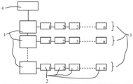
Fig. 2 shows a schematic view of the control electronics according to the invention for an electronic filter for a building ventilation installation according to a second embodiment. In this embodiment, there is a separate master 1 for each chain 3. Each of the master devices 1 is preferably supplied with a second supply voltage of, for example, 24V by a separate power supply. Conversely, the first supply voltage of, for example, 12V can be provided by a single, common power supply. The master devices 1 are connected to each other via a bus. The first master device 1 is configured to be connectable to the building control device 4.
The master device 1 treats it as the former of the first node device 2 of the associated chain 3 when executing the configuration method. The association of the position number with the node device 2 of each of the chains 3 is made in the manner described hereinbefore in accordance with the first embodiment.
The master devices 1 each communicate individually, however via a common bus, with the building control device 4, or with a primary master device which communicates with the building control device 4. The primary master can be the master 1 of the first chain 3 or an additional master without a 24V power supply (or a 230V power supply).
The 24V power supply (or 230V power supply) can be integrated into the main device 1 in all instances or be a separate component.
Fig. 3 shows a schematic view of the control electronics according to the invention for an electronic filter for a building ventilation installation according to a third embodiment. In this embodiment, there are a plurality of master devices 1 and one or more chains 3 of node devices 2 may be connected on each master device 1.
In all embodiments, the node devices 2 of each chain 3 can be numbered consecutively from 1 to n, where the number n represents the number of node devices 2 of the respective chain, or the node devices 2 of all chains 3 can be numbered consecutively from 1 to m, where the number m represents the total number of node devices 2 of the control electronics, or the node devices 2 of all chains 3 connected to the same master device 1 can be numbered consecutively from 1 to k, where the number k represents the total number of node devices 2 connected to the same master device 1.
The invention can realize that: each node device 2 and thus each electronic filter of a large array of electronic filters is activated and parameterized individually. Faults occurring in any node device 2 or electronic filter 2 can thus be localized and eliminated as automatically as possible by corresponding control commands.
The node device 2 supplies the associated electronic filter 2 with a second supply voltage (for example, 24V DC or 230V AC). The supply voltage is preferably transmitted via a galvanic isolation element, that is to say the node device 2 and the associated electronic filter are advantageously galvanically isolated, as is described in PCT application No. PCT/EP 2018/050093.
While embodiments of the invention have been shown and described, it will be apparent to those skilled in the art that many more modifications than mentioned above are possible without departing from the inventive concept.
Claims (7)
1. Control electronics for a plurality of electronic filters of a building ventilation installation, the control electronics comprising:
at least one master device (1) and a node device (2), wherein
A node device (2) can be connected to each of the electronic filters,
the master device (1) or each master device (1) and each node device (2) having a computing unit,
one or more chains (3) of node devices (2) can be connected to the master device (1) or to each of the master devices (1), wherein in each chain (3) a first node device (2) can be connected to the master device (1) to which it belongs and the other node devices (2) of the chain (3) can be connected to the previous node device (2) in each case, such that the node devices (2) of the chain (3) are connected to one another in series, wherein the master device (1) is the former of the first node devices (2) of the connected chain (3) or of the first node devices (2) of the connected chains (3),
each of said node devices (2) of a chain (3) being associated with a location number,
the computing unit of one or more of the master devices (1) is designed to, in a configuration mode, facilitate the computing unit of the first node device (2) of each connected chain (3) to execute a configuration program designed to,
receiving the location number of its former and assigning itself a location number incremented by a value of 1 and storing in the node device (2);
-determining whether a subsequent node device (2) is connected, and if this is the case, pushing the computing unit of the subsequent node device (2) to execute the configuration program.
2. The control electronics of claim 1,
it is characterized in that the preparation method is characterized in that,
each of the node devices (2) has one or more sensors for determining the coding of the connected electronic filter, and the configuration program is additionally designed to determine the coding of the connected electronic filter from the output signal of one or more of the sensors.
3. Control electronics according to claim 1 or 2,
it is characterized in that the preparation method is characterized in that,
one or more of the master devices (1) supply the connected node devices (2) with a supply voltage for the electronic filter, and each of the node devices (2) has a galvanic isolation element for transferring the supply voltage from the node device (2) to the connected electronic filter.
4. The control electronics of claim 1 or 2, wherein each of the electronic filters has a predetermined structural size and includes an ionization stage and a current collector stage, and the control of each of the electronic filters is performed by presetting an ionization current flowing through the ionization stage and a direct current high voltage to be applied to the current collector stage,
it is characterized in that the preparation method is characterized in that,
the at least one master device (1) can be connected to a building control device (4) or is part of a building control device (4),
the at least one master device (1) is designed to transmit the control signals transmitted by the building control device (4) or control signals derived therefrom to the node device (2), and
each of the node devices (2) is designed to determine, for the associated electronic filter, the ionization current to be set as a function of the transmitted control signal and optionally the structural size of the connected electronic filter and/or to determine the direct voltage to be applied to the current collector as a function of the transmitted control signal.
5. The control electronics of claim 4,
it is characterized in that the preparation method is characterized in that,
the control signal transmitted to the node device (2) is the current magnitude of the air volume flow through the ventilation channel provided with the electronic filter.
6. The control electronics of claim 3, wherein each of said electronic filters has a predetermined structural size and includes an ionization stage and a current collector stage, and control of each of said electronic filters is performed by presetting an ionization current flowing through said ionization stage and a DC high voltage to be applied to said current collector stage,
it is characterized in that the preparation method is characterized in that,
the at least one master device (1) can be connected to a building control device (4) or is part of a building control device (4),
the at least one master device (1) is designed to transmit the control signals transmitted by the building control device (4) or control signals derived therefrom to the node device (2), and
each of the node devices (2) is designed to determine, for the associated electronic filter, the ionization current to be set as a function of the transmitted control signal and optionally the structural size of the connected electronic filter and/or to determine the direct voltage to be applied to the current collector as a function of the transmitted control signal.
7. The control electronics of claim 6,
it is characterized in that the preparation method is characterized in that,
the control signal transmitted to the node device (2) is the current magnitude of the air volume flow through the ventilation channel provided with the electronic filter.
Applications Claiming Priority (3)
| Application Number | Priority Date | Filing Date | Title |
|---|---|---|---|
| CH00096/17 | 2017-01-30 | ||
| CH00096/17A CH713392A1 (en) | 2017-01-30 | 2017-01-30 | Control electronics for several electrostatic filters. |
| PCT/EP2018/052090 WO2018138315A1 (en) | 2017-01-30 | 2018-01-29 | Control electronics for multiple electric filters |
Publications (2)
| Publication Number | Publication Date |
|---|---|
| CN110235067A CN110235067A (en) | 2019-09-13 |
| CN110235067B true CN110235067B (en) | 2022-04-26 |
Family
ID=61094519
Family Applications (1)
| Application Number | Title | Priority Date | Filing Date |
|---|---|---|---|
| CN201880008985.9A Active CN110235067B (en) | 2017-01-30 | 2018-01-29 | Control electronics for multiple electronic filters |
Country Status (13)
| Country | Link |
|---|---|
| US (1) | US11079133B2 (en) |
| EP (1) | EP3555712B1 (en) |
| JP (1) | JP7103666B2 (en) |
| KR (1) | KR20190109425A (en) |
| CN (1) | CN110235067B (en) |
| AU (1) | AU2018212601B2 (en) |
| BR (1) | BR112019015685A2 (en) |
| CA (1) | CA3051633C (en) |
| CH (1) | CH713392A1 (en) |
| DK (1) | DK3555712T3 (en) |
| RU (1) | RU2752102C2 (en) |
| SG (1) | SG11201906651XA (en) |
| WO (1) | WO2018138315A1 (en) |
Families Citing this family (5)
| Publication number | Priority date | Publication date | Assignee | Title |
|---|---|---|---|---|
| US11287429B2 (en) | 2018-09-25 | 2022-03-29 | Siemens Healthcare Diagnostics Inc. | Compositions, kits, and methods for multiplex assays to correct for biotin interference in target analyte measurements |
| CN109812944B (en) * | 2019-03-20 | 2023-12-01 | 杭州地铁运营有限公司 | Air valve control circuit board of ventilation air conditioning system |
| CN112113292A (en) * | 2020-10-13 | 2020-12-22 | 山东新华医疗器械股份有限公司 | Medical air disinfection purifier with double working modes |
| US20230375208A1 (en) * | 2020-10-23 | 2023-11-23 | Zehnder Group International Ag | Method of operating an air cleaning cluster |
| CN112628935A (en) * | 2020-12-22 | 2021-04-09 | 丽水市知源科技有限公司 | Market air conditioning system based on Internet of things and control method thereof |
Family Cites Families (29)
| Publication number | Priority date | Publication date | Assignee | Title |
|---|---|---|---|---|
| JPS57119857A (en) * | 1981-01-19 | 1982-07-26 | Takuma Co Ltd | Control method for electrostatic precipitator |
| JPH08328618A (en) * | 1995-05-31 | 1996-12-13 | Showa Tekko Kk | Address setting device of terminal equipment |
| US5578112A (en) * | 1995-06-01 | 1996-11-26 | 999520 Ontario Limited | Modular and low power ionizer |
| WO2000002345A2 (en) * | 1998-07-02 | 2000-01-13 | Amino Holdings Limited | Electronic system architecture |
| ES2200367T3 (en) * | 1998-09-18 | 2004-03-01 | F.L. Smidth Airtech A/S | A METHOD OF OPERATION OF AN ELECTROSTATIC PRECIPITATOR. |
| US6576046B2 (en) * | 2000-10-19 | 2003-06-10 | Fedders Corporation | Modular electrostatic precipitator system |
| JP2004077018A (en) * | 2002-08-19 | 2004-03-11 | Fujitsu General Ltd | Air-conditioner network system |
| DE10261174B3 (en) * | 2002-12-20 | 2004-06-17 | Daimlerchrysler Ag | Automatic addressing method for control devices connected to data bus system with series or ring structure |
| DE102004036210B4 (en) * | 2004-07-26 | 2006-08-31 | Siemens Ag | Control device and control method for electrostatic precipitators with a configurable number of parallel and serial filter zones |
| JP3979436B1 (en) * | 2006-03-09 | 2007-09-19 | ダイキン工業株式会社 | Air conditioner and address setting method in air conditioner |
| US8400061B2 (en) * | 2007-07-17 | 2013-03-19 | I/O Controls Corporation | Control network for LED-based lighting system in a transit vehicle |
| US8397527B2 (en) * | 2007-07-30 | 2013-03-19 | Jack V. Miller | Energy saving integrated lighting and HVAC system |
| EP2031568A1 (en) * | 2007-08-28 | 2009-03-04 | CC Trust Group AG | Selling device and method for operating such selling machine and product for such a selling machine |
| US8291380B2 (en) * | 2008-03-05 | 2012-10-16 | International Business Machines Corporation | Methods for configuring software package |
| AU2009290588B2 (en) * | 2008-09-15 | 2015-11-26 | Haier Us Appliance Solutions, Inc. | Energy management of household appliances |
| US8296488B2 (en) * | 2009-04-27 | 2012-10-23 | Abl Ip Holding Llc | Automatic self-addressing method for wired network nodes |
| WO2012075038A1 (en) | 2010-12-01 | 2012-06-07 | Michael Gordon | Vending modified climate control device |
| US20140076291A1 (en) * | 2011-08-09 | 2014-03-20 | Clean Air Power, Inc | Method and apparatus for controlling premixed combustion in a multimode engine |
| US8922971B2 (en) * | 2012-01-13 | 2014-12-30 | Clean Air Group, Inc. | Integrated bi-polar ionization air purification for fan-powered air distribution devices |
| EP2841740B1 (en) * | 2012-04-26 | 2020-04-01 | General Electric Company | System and method of recirculating exhaust gas for use in a plurality of flow paths in a gas turbine engine |
| US20140022941A1 (en) * | 2012-07-17 | 2014-01-23 | The Procter & Gamble Company | Systems and methods for networking consumer devices |
| US20140173081A1 (en) * | 2012-11-13 | 2014-06-19 | Joshua P. Knapp | Method and apparatus for discovery and enumeration of sequentially networked devices |
| US20140223048A1 (en) * | 2013-02-06 | 2014-08-07 | Infineon Technologies Ag | Communication network and method for communicating in a communication network |
| BR112015019014A2 (en) * | 2013-02-07 | 2017-07-18 | Honeywell Int Inc | building control system for controlling one or more building components servicing a building, and method of controlling one or more separate air conditioning units servicing a building |
| DE112013006713T5 (en) * | 2013-02-21 | 2015-11-12 | Mitsubishi Electric Corporation | Networked air conditioning, repeaters and program |
| US9737842B2 (en) * | 2014-04-25 | 2017-08-22 | Fellowes, Inc. | Air purifier with intelligent sensors and airflow |
| CN204496182U (en) * | 2015-04-03 | 2015-07-22 | 周颖 | Based on the Smart Home ventilating system of Internet of Things |
| US10215430B2 (en) * | 2015-06-15 | 2019-02-26 | Lunatech, Llc | Electronic vapor and analysis with HVAC integration |
| CN106354041B (en) * | 2016-10-24 | 2018-08-28 | 上海革创电子科技有限公司 | A kind of tandem type multinode industrial automation control system of non-all-key parallel bus |
-
2017
- 2017-01-30 CH CH00096/17A patent/CH713392A1/en not_active Application Discontinuation
-
2018
- 2018-01-29 DK DK18702257.9T patent/DK3555712T3/en active
- 2018-01-29 RU RU2019122140A patent/RU2752102C2/en active
- 2018-01-29 JP JP2019528056A patent/JP7103666B2/en active Active
- 2018-01-29 CA CA3051633A patent/CA3051633C/en active Active
- 2018-01-29 AU AU2018212601A patent/AU2018212601B2/en active Active
- 2018-01-29 CN CN201880008985.9A patent/CN110235067B/en active Active
- 2018-01-29 SG SG11201906651XA patent/SG11201906651XA/en unknown
- 2018-01-29 BR BR112019015685A patent/BR112019015685A2/en unknown
- 2018-01-29 EP EP18702257.9A patent/EP3555712B1/en active Active
- 2018-01-29 KR KR1020197022228A patent/KR20190109425A/en not_active IP Right Cessation
- 2018-01-29 WO PCT/EP2018/052090 patent/WO2018138315A1/en unknown
- 2018-01-29 US US16/476,067 patent/US11079133B2/en active Active
Also Published As
| Publication number | Publication date |
|---|---|
| JP2020509442A (en) | 2020-03-26 |
| AU2018212601A1 (en) | 2019-07-25 |
| EP3555712B1 (en) | 2020-04-08 |
| SG11201906651XA (en) | 2019-08-27 |
| JP7103666B2 (en) | 2022-07-20 |
| KR20190109425A (en) | 2019-09-25 |
| RU2019122140A3 (en) | 2021-05-18 |
| US20200003445A1 (en) | 2020-01-02 |
| CN110235067A (en) | 2019-09-13 |
| BR112019015685A2 (en) | 2020-04-07 |
| EP3555712A1 (en) | 2019-10-23 |
| CH713392A1 (en) | 2018-07-31 |
| CA3051633A1 (en) | 2018-08-02 |
| WO2018138315A1 (en) | 2018-08-02 |
| US11079133B2 (en) | 2021-08-03 |
| CA3051633C (en) | 2023-06-13 |
| DK3555712T3 (en) | 2020-05-18 |
| AU2018212601B2 (en) | 2021-10-21 |
| RU2019122140A (en) | 2021-03-01 |
| RU2752102C2 (en) | 2021-07-22 |
Similar Documents
| Publication | Publication Date | Title |
|---|---|---|
| CN110235067B (en) | Control electronics for multiple electronic filters | |
| US20050289279A1 (en) | Power supply system and method thereof | |
| KR20160039680A (en) | Smart power system | |
| US20160239007A1 (en) | Rugged remote universal input/output system | |
| KR920020150A (en) | Current controller of air conditioner system | |
| US9497813B2 (en) | LED lighting arrangement and method of controlling a LED lighting arrangement | |
| CN104101063B (en) | Air conditioner | |
| US20210243867A1 (en) | Power and communication adapter for lighting system for indoor grow application | |
| CN101568890A (en) | Two-wire field device for process automation technology for connecting at least one sensor element | |
| CN112379611B (en) | Environment monitoring control equipment | |
| WO2021016478A1 (en) | Universal adapter for lighting system for indoor grow application | |
| US10073473B2 (en) | Indoor digital centralized controller system, air conditioning system comprising the same, and heating/cooling device comprising the same | |
| CN106533321B (en) | Motor control circuit and use method | |
| CN110392981B (en) | Switch operating device for door operator | |
| UA153030U (en) | CENTRALIZED SYSTEM OF AUTOMATED MASS MANAGEMENT OF ELECTRICAL HEATING SOURCES | |
| CN202792303U (en) | Internal adhesion-type intelligentized ozone air sterilization generator | |
| CN111641429A (en) | Automatically controlled subassembly with thing networking communication function | |
| CN106681283A (en) | Electric module and intelligent integrated control system based on the electric module | |
| JPS62268329A (en) | Power line carrier control system |
Legal Events
| Date | Code | Title | Description |
|---|---|---|---|
| PB01 | Publication | ||
| PB01 | Publication | ||
| SE01 | Entry into force of request for substantive examination | ||
| SE01 | Entry into force of request for substantive examination | ||
| GR01 | Patent grant | ||
| GR01 | Patent grant |