KR20190042135A - Floating solar power system with hight adjustment pontoons - Google Patents
Floating solar power system with hight adjustment pontoons Download PDFInfo
- Publication number
- KR20190042135A KR20190042135A KR1020170133664A KR20170133664A KR20190042135A KR 20190042135 A KR20190042135 A KR 20190042135A KR 1020170133664 A KR1020170133664 A KR 1020170133664A KR 20170133664 A KR20170133664 A KR 20170133664A KR 20190042135 A KR20190042135 A KR 20190042135A
- Authority
- KR
- South Korea
- Prior art keywords
- buoyant body
- water
- solar cell
- buoyant
- buoyancy
- Prior art date
Links
- 238000007667 floating Methods 0.000 title abstract description 11
- XLYOFNOQVPJJNP-UHFFFAOYSA-N water Substances O XLYOFNOQVPJJNP-UHFFFAOYSA-N 0.000 claims abstract description 56
- 238000000034 method Methods 0.000 claims abstract description 27
- 230000008878 coupling Effects 0.000 claims abstract description 14
- 238000010168 coupling process Methods 0.000 claims abstract description 14
- 238000005859 coupling reaction Methods 0.000 claims abstract description 14
- 238000005192 partition Methods 0.000 claims abstract description 5
- 241000251468 Actinopterygii Species 0.000 claims abstract description 4
- 230000008569 process Effects 0.000 claims abstract description 3
- 238000010248 power generation Methods 0.000 claims description 14
- 230000008859 change Effects 0.000 claims description 9
- 230000006378 damage Effects 0.000 claims description 9
- 239000000463 material Substances 0.000 claims description 8
- 239000000853 adhesive Substances 0.000 claims description 4
- 230000001070 adhesive effect Effects 0.000 claims description 4
- 230000006870 function Effects 0.000 claims description 4
- 238000004891 communication Methods 0.000 claims description 2
- 238000005520 cutting process Methods 0.000 claims description 2
- 238000001514 detection method Methods 0.000 claims description 2
- 239000002184 metal Substances 0.000 claims description 2
- 229910052751 metal Inorganic materials 0.000 claims description 2
- 238000005070 sampling Methods 0.000 claims description 2
- 238000007599 discharging Methods 0.000 claims 1
- 230000002708 enhancing effect Effects 0.000 claims 1
- 229910052755 nonmetal Inorganic materials 0.000 claims 1
- 238000011017 operating method Methods 0.000 claims 1
- 230000001965 increasing effect Effects 0.000 abstract description 7
- 241001465754 Metazoa Species 0.000 abstract 1
- 230000006866 deterioration Effects 0.000 abstract 1
- 230000002265 prevention Effects 0.000 abstract 1
- 235000015170 shellfish Nutrition 0.000 abstract 1
- 230000035939 shock Effects 0.000 abstract 1
- 239000002699 waste material Substances 0.000 abstract 1
- 230000001276 controlling effect Effects 0.000 description 6
- 238000010586 diagram Methods 0.000 description 6
- 238000004519 manufacturing process Methods 0.000 description 5
- 230000000694 effects Effects 0.000 description 4
- 238000009434 installation Methods 0.000 description 4
- 230000008901 benefit Effects 0.000 description 3
- 230000003247 decreasing effect Effects 0.000 description 2
- 230000007613 environmental effect Effects 0.000 description 2
- 239000012744 reinforcing agent Substances 0.000 description 2
- 238000007789 sealing Methods 0.000 description 2
- XEEYBQQBJWHFJM-UHFFFAOYSA-N Iron Chemical group [Fe] XEEYBQQBJWHFJM-UHFFFAOYSA-N 0.000 description 1
- 229910000831 Steel Inorganic materials 0.000 description 1
- 229920006328 Styrofoam Polymers 0.000 description 1
- 239000011013 aquamarine Substances 0.000 description 1
- 230000003190 augmentative effect Effects 0.000 description 1
- 230000004888 barrier function Effects 0.000 description 1
- 239000003795 chemical substances by application Substances 0.000 description 1
- 230000003028 elevating effect Effects 0.000 description 1
- 238000003912 environmental pollution Methods 0.000 description 1
- 230000036541 health Effects 0.000 description 1
- 238000012423 maintenance Methods 0.000 description 1
- 238000012545 processing Methods 0.000 description 1
- 238000003908 quality control method Methods 0.000 description 1
- 230000001105 regulatory effect Effects 0.000 description 1
- 238000011160 research Methods 0.000 description 1
- 239000010959 steel Substances 0.000 description 1
- 238000003860 storage Methods 0.000 description 1
- 239000008261 styrofoam Substances 0.000 description 1
- 230000009182 swimming Effects 0.000 description 1
Images


Classifications
-
- B—PERFORMING OPERATIONS; TRANSPORTING
- B63—SHIPS OR OTHER WATERBORNE VESSELS; RELATED EQUIPMENT
- B63B—SHIPS OR OTHER WATERBORNE VESSELS; EQUIPMENT FOR SHIPPING
- B63B35/00—Vessels or similar floating structures specially adapted for specific purposes and not otherwise provided for
- B63B35/44—Floating buildings, stores, drilling platforms, or workshops, e.g. carrying water-oil separating devices
-
- H—ELECTRICITY
- H01—ELECTRIC ELEMENTS
- H01L—SEMICONDUCTOR DEVICES NOT COVERED BY CLASS H10
- H01L31/00—Semiconductor devices sensitive to infrared radiation, light, electromagnetic radiation of shorter wavelength or corpuscular radiation and specially adapted either for the conversion of the energy of such radiation into electrical energy or for the control of electrical energy by such radiation; Processes or apparatus specially adapted for the manufacture or treatment thereof or of parts thereof; Details thereof
- H01L31/04—Semiconductor devices sensitive to infrared radiation, light, electromagnetic radiation of shorter wavelength or corpuscular radiation and specially adapted either for the conversion of the energy of such radiation into electrical energy or for the control of electrical energy by such radiation; Processes or apparatus specially adapted for the manufacture or treatment thereof or of parts thereof; Details thereof adapted as photovoltaic [PV] conversion devices
- H01L31/042—PV modules or arrays of single PV cells
-
- H—ELECTRICITY
- H02—GENERATION; CONVERSION OR DISTRIBUTION OF ELECTRIC POWER
- H02S—GENERATION OF ELECTRIC POWER BY CONVERSION OF INFRARED RADIATION, VISIBLE LIGHT OR ULTRAVIOLET LIGHT, e.g. USING PHOTOVOLTAIC [PV] MODULES
- H02S20/00—Supporting structures for PV modules
- H02S20/30—Supporting structures being movable or adjustable, e.g. for angle adjustment
-
- B—PERFORMING OPERATIONS; TRANSPORTING
- B63—SHIPS OR OTHER WATERBORNE VESSELS; RELATED EQUIPMENT
- B63B—SHIPS OR OTHER WATERBORNE VESSELS; EQUIPMENT FOR SHIPPING
- B63B35/00—Vessels or similar floating structures specially adapted for specific purposes and not otherwise provided for
- B63B35/44—Floating buildings, stores, drilling platforms, or workshops, e.g. carrying water-oil separating devices
- B63B2035/4433—Floating structures carrying electric power plants
- B63B2035/4453—Floating structures carrying electric power plants for converting solar energy into electric energy
-
- B—PERFORMING OPERATIONS; TRANSPORTING
- B63—SHIPS OR OTHER WATERBORNE VESSELS; RELATED EQUIPMENT
- B63B—SHIPS OR OTHER WATERBORNE VESSELS; EQUIPMENT FOR SHIPPING
- B63B2209/00—Energy supply or activating means
- B63B2209/18—Energy supply or activating means solar energy
-
- B—PERFORMING OPERATIONS; TRANSPORTING
- B63—SHIPS OR OTHER WATERBORNE VESSELS; RELATED EQUIPMENT
- B63B—SHIPS OR OTHER WATERBORNE VESSELS; EQUIPMENT FOR SHIPPING
- B63B2221/00—Methods and means for joining members or elements
- B63B2221/10—Methods and means for joining members or elements using adhesives
-
- Y—GENERAL TAGGING OF NEW TECHNOLOGICAL DEVELOPMENTS; GENERAL TAGGING OF CROSS-SECTIONAL TECHNOLOGIES SPANNING OVER SEVERAL SECTIONS OF THE IPC; TECHNICAL SUBJECTS COVERED BY FORMER USPC CROSS-REFERENCE ART COLLECTIONS [XRACs] AND DIGESTS
- Y02—TECHNOLOGIES OR APPLICATIONS FOR MITIGATION OR ADAPTATION AGAINST CLIMATE CHANGE
- Y02E—REDUCTION OF GREENHOUSE GAS [GHG] EMISSIONS, RELATED TO ENERGY GENERATION, TRANSMISSION OR DISTRIBUTION
- Y02E10/00—Energy generation through renewable energy sources
- Y02E10/50—Photovoltaic [PV] energy
Landscapes
- Engineering & Computer Science (AREA)
- Architecture (AREA)
- Civil Engineering (AREA)
- Structural Engineering (AREA)
- Chemical & Material Sciences (AREA)
- Combustion & Propulsion (AREA)
- Mechanical Engineering (AREA)
- Ocean & Marine Engineering (AREA)
- Physics & Mathematics (AREA)
- Condensed Matter Physics & Semiconductors (AREA)
- Electromagnetism (AREA)
- General Physics & Mathematics (AREA)
- Computer Hardware Design (AREA)
- Microelectronics & Electronic Packaging (AREA)
- Power Engineering (AREA)
- Photovoltaic Devices (AREA)
Abstract
Description
본 발명은 공기압과 수압을 조절하여, 부력체의 높이 및 경사를 변경할 수 있는 수상 구조물과 이를 이용한 태양광 발전장치 운영에 관한 것이다.BACKGROUND OF THE INVENTION 1. Field of the Invention [0001] The present invention relates to a water structure capable of changing the height and inclination of a buoyant body by controlling air pressure and water pressure, and a solar power generator using the same.
상기 부력체는 하부 개방구조나 밸브를 조절하는 방법으로, 부력과 무게를 제어함으로서, 태풍이나 자연재해로부터 수상구조물을 안전하게 운영할 수 있도록 하고, 제어수단을 통해 태양의 위치를 추적하는 추적식 수상태양광 발전소 운영이 가능한 특징이 있다.The buoyant body is a method of regulating the bottom opening structure and the valve. By controlling the buoyancy and weight, it is possible to operate the water structure safely from typhoon or natural disaster, and to track the position of the sun through the control means. There is a feature that enables the operation of a state dimming plant.
일반적으로 어업이나 해상스포츠, 선박의 정박에는 부력 구조체(폰툰)을 사용하게 되는데, 이 부력체는 주로 내부가 비어있는 중공형과 내부에 스츠로폴과 같은 부력제를 채운 삽입형이 일반적이다.Generally, a buoyant structure (pontoon) is used for fishing, marine sports, and anchorage of a ship. The buoyant body is generally a hollow type having hollow inside and a buoyancy type filled with buoyant agent such as styrofoam inside.
이 방법들은 좌우 두면을 사출하여 붙이거나, 추가적으로 내부에 스츠로폴을 충진 하는 등의 추가 가공이 필요해서 생산 속도가 낮고, 절차도 복잡해서 생산성이 낮으며, 가격도 상대적으로 높다. These methods require additional processing, such as injecting the left and right sides, and additionally filling the inside with the stolopol, so that the production speed is low, the procedure is complicated, the productivity is low, and the price is relatively high.
또한 상부에 설치되는 구조물을 고정하기 위해 철재 구조물을 많이 사용하게 되고, 다시 무게가 늘어나서 부력체를 더 사용해야하는 악순환이 발생하게 된다.Also, in order to fix the structure to be installed on the upper part, a steel structure is frequently used, and the weight is increased again, resulting in a vicious cycle in which a buoyant body is required to be used more.
뿐만 아니라 중공형 부력체는 파손시 부력을 상실하는 문제가 있고, 삽입형 부력체는 파손시 환경파괴와 생태계를 교란시키는 미세 스츠로폴 조각으로 어류의 생명을 위협하고, 결국 인간의 밥상위에 올라와 인간의 건강을 해치게 되는 문제가 발생하고 있다.In addition, the hollow buoyant body has the problem of losing its buoyancy when it is broken, and the insertable buoyant body is a micro-struck pole piece that disturbs the environmental destruction and the ecosystem at the time of breakage, threatens the life of the fish, There is a problem that the health of the user is deteriorated.
또한 선행기술과 현재 판매중인 제품들의 형태에서 파악할 수 있듯이, 부력체는 밀폐와 수밀, 내용물의 품질 등이 부력 효과에 크게 작용함으로 생산 단가가 높고, 생산할 수 있는 크기가 작고, 품질관리가 어려운 문제가 있다.As can be understood from the prior art and the types of products currently on sale, the buoyancy body has a high production cost, a small size to be produced, and difficulty in quality control since sealing, watertightness, and quality of contents greatly affect the buoyancy effect .
또한 부력체를 크기가 작기 때문에 충분한 부력을 얻기 위해서 여러 개를 묶어서 큰 형태를 만드는 방법으로 수상구조물을 제작하게 되는데, 결합부품의 숫자가 늘어나서 제작이나 관리에 더 많은 비용이 될 뿐만 아니라, 결합부품은 파도나 바람으로 인해 파손되는 확률이 높기 때문에 더 많은 관리 비용이 발생할 확률이 높아진다.In addition, since the buoyant body is small in size, the water structure is manufactured by bundling several pieces in order to obtain a sufficient buoyancy. In addition, the number of coupled parts is increased, Are more likely to be damaged due to waves or winds, which increases the likelihood of more administrative costs being incurred.
이는 수상 태양광 발전소처럼 구조물의 가격과 설치비가 발전소 운영에 큰 변수가 되는 사업수행에 중요한 문제가 되고 있다. This is an important issue for the project, where the cost and installation cost of the structure, such as a water solar power plant, is a big variable for plant operation.
등록된 선행 특허 중에 밸러스트 탱크를 이용하는 방식의 제 10-1575155는 선박의 밸러스트 탱크를 그대로 차용한 것으로서, 본 발명의 공기압을 조절하고, 물은 무게와 공기유출의 목적을 가진다고 할 수 없다. 10-1575155, in which a ballast tank is used in the registered prior patent, is a vessel in which the ballast tank of a ship is intact, it can not be said that the air pressure of the present invention is controlled, and the water does not have the purpose of weight and airflow.
본 발명은 상기 기술한 문제를 해결하기 위해 안출한 것으로서, The present invention has been made to solve the above-mentioned problems,
단위 부력체를 한쪽 면으로 사출이 가능해서 생산속도를 높이는 것을 목적으로 한다. The unit buoyant body can be injected onto one side, thereby increasing the production speed.
날씨변화와 사용목적에 적절하게 대응이 가능한 부력체를 저렴하게 구현하는 것을 목적으로 한다.The object of the present invention is to provide a buoyant body which can cope with the weather change and the purpose of use inexpensively.
수밀이 용이하고, 부력체가 일부 파손 되는 경우에도 침수되지 않는 부력체를 목적으로 한다.It is aimed at a buoyant body which is easily watertight and does not flood even when the buoyant body is partially damaged.
태풍이나 파도에서 강한 결속력으로 좌초나 파손이 적은 부력체를 목적으로 한다.It is aimed at a buoyant body with little stranding or breakage due to strong binding force in typhoon or wave.
태양의 이동경로를 따라서 경사나 방위를 변경하여 설치비 대비 높은 전력생산 효율을 구현하는 것을 목적으로 한다.And aims at realizing high power production efficiency compared to installation cost by changing the inclination or orientation along the movement path of the sun.
본 발명은 다음과 같은 목적을 실현하고자 한다. The present invention aims to realize the following objects.
단위 부력체의 부력을 공기와 물을 이용하여 증감할 수 있는 특징이 있다.The buoyant force of the unit buoyant body can be increased or decreased by using air and water.
단위 부력체는 내부가 비어 있어서, 태풍이나 돌풍 같은 자연재해와 인위적 사고로 인해 파손되는 경우에도 환경파괴의 우려를 최소화 하는 특징이 있다. The unit buoyancy structure is characterized by the fact that the inside is empty, thereby minimizing the concern of environmental destruction even if it is damaged due to natural disasters such as typhoons or gusts and artificial accidents.
단위 부력체를 이용한 수상 구조물은 단위 부력체의 내외부에 설치된 센서들에서 수집되는 정보를 통해, 부력체의 높이를 낮추어 돌풍으로 인한 뒤집힘이나, 태풍으로 인한 떠내려감을 미연에 방지 하고, 일부 파손의 경우에도 연결된 부력체의 공기압을 조절하여 하중을 충분히 분산시키는 특징이 있다. The augmented structure using the unit buoyant body lowers the height of the buoyant body by the information collected from the sensors installed inside and outside the unit buoyant body to prevent overturning due to gust wind or floating due to typhoon, The load is sufficiently dispersed by adjusting the air pressure of the buoyant body connected to the buoyant body.
단위 부력체로 구성된 수상 구조물은 수밀이나 밀폐의 부담이 적어서 크게 제작이 가능한 특징이 있다.A water structure composed of a unit buoyancy structure has a feature that it can be manufactured largely because the burden of watertightness and sealing is small.
단위 부력체는 공기압 증가를 통해서, 기존 부력체에 비해 높은 부력을 만들어 낼 수 있는 특징이 있다. The unit buoyant body is characterized in that the buoyant force can be made higher than the conventional buoyant body by increasing the air pressure.
단위 부력체를 사용한 수상 구조물은 높은 부력으로 설치단가가 낮추고, 다양한 분야에 적용이 가능한 특징이 있다. The buoyant structure using the buoyant buoyant body is characterized by high buoyancy and low installation cost and applicable to various fields.
본 발명에 의하면, 내부가 비어있는 단순한 구조를 이용하기 때문에 스치로풀류 등 물리적 부력문질에 의한 환경을 방지하는 효과가 있다.According to the present invention, since a simple structure having an empty interior is used, there is an effect of preventing an environment caused by physical buoyancy or the like, such as a squeeze.
본 발명에 의하면, 승강방식을 이용한 수상구조물은 공기압에 의해 더 많은 하중을 견딜 수 있어서 경제적인 절감 효과가 있다.According to the present invention, the water structure using the lifting system can withstand more loads by the air pressure, thereby reducing the economic effect.
본 발명에 의하면, 내부가 비어있는 단순한 구조는 단위 구조물을 포개어 적재할 수 있도록 하여 보관시 공간 절약이 되고 이동시에 이동수단을 최소화 하는 효과가 있다.According to the present invention, a simple structure in which the interior is hollow allows a unit structure to be stacked and stacked, thereby saving space during storage and minimizing the moving means during movement.
본 발명에 의하면, 수상구조물의 설치되는 센서들은 물의 흐름, 상태, 바람과 진동, 충돌 등을 감지하여 환경감시가 가능하고, 이를 이용하여 운영인력을 최소화 하는 효과가 있다. According to the present invention, the sensors installed on the water structure detect the flow of water, the state, the wind, the vibration, the collision, and the like, and can monitor the environment.
본 발명에 의하면, 수위 조절 방식의 수상 구조물은 태풍이나 녹조, 적조시에 수면 또는 아래로 이동함으로서, 구조물의 안전을 유지하거나, 어류를 방사하의 폐사를 막는 효과가 있다.According to the present invention, the water level control type water structure has the effect of maintaining the safety of the structure or preventing the dead fish from being spun by moving the water surface or downward when typhoon, green tide, or red tide.
본 발명에 의하면, 공기압 조절방식 승강방법을 적용한 수상구조물은 수상에 설치되는 태양광 발전소 또는 풍력 발전소 등의 중량물을 효과적으로 운영할 수 있도록 하는 효과가 있다. According to the present invention, a water structure using an air pressure control type elevating method is effective in effectively operating heavy equipment such as a solar power plant or a wind power plant installed on a watercraft.
본 발명에 의하면, 공기압을 조절방식의 수상 구조물은 태양광 발전장치를 상하좌우로 이동시킬 수 있어서 태양광 발전의 효율을 향상 시키는 효과가 있다.According to the present invention, the pneumatic pressure type water structure can move the solar power generation device vertically and horizontally, thereby improving the efficiency of solar power generation.
도1은 본 발명의 수상태양광 발전장치의 측면도
도2는 본 발명의 부력체 측단면도
도3은 본 발명의 부력체 입단면도
도4은 본 발명의 부력체 하부 커버 부착시 측단면도
도5는 본 발명의 개폐형 하부커버를 설치한 부력체 측단면도
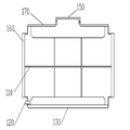
도6는 본 발명의 부력체군 측면도
도7는 본 발명의 부력체 고정 방법 예시도
도8은 본 발명의 부력체를 이용한 경사가변형 수상 태양광 발전장치
도9은 본 발명의 엑추에이터를 이용한 경사가변형 수상 태양광 발전장치
도10은 본 발명의 태양광 구조물의 경사가변시 엑추에이터 동작예시도
도10는 본 발명의 태양광발전장치 제어부 블록도
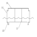
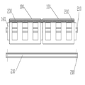
도11은 본 발명의 수상태양광 발전장치의 측면도
도13은 본 발명의 활용 예시도1 is a side view of the water-state photovoltaic device of the present invention
Fig. 2 is a side sectional view of the buoyant body according to the present invention
Figure 3 is a cross-sectional view of the buoyant body of the present invention
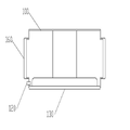
4 is a side sectional view of the buoyant lower cover of the present invention
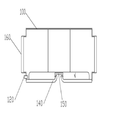
5 is a side sectional view of the buoyant body provided with the openable and closable lower cover of the present invention
6 is a side view of the buoyancy body of the present invention
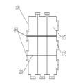
Figure 7 is an illustration of a method of fixing a buoyant body of the present invention
Fig. 8 is a view showing an example of an inclined variable-
Fig. 9 is a view showing an example of an inclined variable-
10 is a view illustrating an example of the operation of the actuator when the inclination of the solar photovoltaic structure according to the present invention is varied
Fig. 10 is a block diagram of the solar power generator control block of the present invention
11 is a side view of the water-state photovoltaic device of the present invention
FIG. 13 is a diagram illustrating an application example of the present invention
이하에서 본 발명의 가장 바람직한 실시 예를 첨부시킨 도면에 따라서 상세하게 설명하기로 한다.BEST MODE FOR CARRYING OUT THE INVENTION The most preferred embodiments of the present invention will now be described in detail with reference to the accompanying drawings.
본 발명은 높낮이 조절이 가능한 부력체를 이용한 수상 태양광 발전소의 구현과 운영에 관한 것으로서, 기존 제품들의 문제점인 바람에 의한 불안정한 운영, 파손에 의한 환경오염, 낮은 경제성 등의 문제를 해결하기 위해 고안된 것이다.The present invention relates to the implementation and operation of an aquifer power plant using a buoyant body capable of adjusting the height, and is designed to solve problems such as unstable operation due to wind, environmental pollution caused by wind damage, low economic efficiency, etc. will be.
본 발명에 의한 부력체는 하부가 개방되어 있어서, 기존 제품보다는 상대적으로 밀폐의 중요성이 상대적으로 낮아서 기밀을 요하는 정밀한 작업 없이 경제적이고, 하부가 파손되어 발생하는 침몰을 막을 수 있다는 장점이 있을 뿐만 아니라, 개폐가 가능한 하부커버를 적용하면 하중을 제어할 수 있어서, 물결이나 바람이 잔잔한 지역에서만 사용이 가능한 기존 제품의 한계점을 극복할 수 있다.Since the lower portion of the buoyant body according to the present invention is opened, the importance of the airtightness relative to the existing products is relatively low, so that it is economical without precise operation requiring airtightness. However, the lower cover that can be opened and closed can control the load, which can overcome the limitations of existing products that can only be used in areas where there are waves and winds.
뿐만 아니라 부력체의 높낮이를 제어함으로써 상단에 설치된 태양전지의 기울기를 변경할 수 있으며, 형태에 따라서는 태양의 위치를 추적하는 기능을 수행할 수 있다.In addition, by controlling the height of the buoyant body, it is possible to change the slope of the solar cell installed at the top, and to perform the function of tracking the position of the sun depending on the shape.
더 나아가 태양전지 지지구조(300)에 엑추에이터(350)을 추가하면 사람의 관리 없이 자동으로 태양의 위치를 추적할 수 있는 장점이 있다. Furthermore, the addition of the
또한 부력체를 서로 끼울수 있는 돌기(160)를 사용하여 움직임을 제한함으로써 좀 더 강력한 결합이 가능해지고, 결속테이프(200)와 ㄷ자 형태의 외부고정부(210)는 쐐기처럼 삽입되기도 하지만 접착제를 사용해 좀 더 강력한 결합이 용이해 지는 장점이 있다. Further, by using the
도1은 본 발명에 의한 부력체를 이용한 수상태양광 발전장치의 측면도로서, 수면(105)에 떠있는 두 개의 부력체(100) 사이에 상하 이동과 결합이 가능하도록 구비된 슬라이더(370) 또는 힌지 구조를 결합한 상태를 도식한 것이다.FIG. 1 is a side view of a water-based photovoltaic power generation apparatus using a buoyant body according to the present invention. FIG. 1 is a perspective view of a
태양전지 지지구조(300) 330 엑추에이터(350) 상단의 도면은 좌측(전방)의 부력체를 기준으로, 우측(후방)의 부력체에 공기를 주입하는 방법으로 수면에 가까이 부상한 것을 도식한 것이며, 부력체의 상단에 설치된 태양전지 지지구조(300)의 연결부는 힌지 구조로 부력체의 이동에 대응할 수 있도록 구현하는 것이 바람직하다. Solar
또한 태양전지 거치대(330)의 경사를 변경하기 위해 설치되는 태양전지 지지구조(300)의 가변 다리구조에는 엑추에이터(350)와 가변 후 고정하는 쐐기(360)가 설치되어 있는 것이 특징이다.Further, the variable bridge structure of the solar
상세한 설명은 추가된 도면을 통해 상세 설명하기로 한다.The detailed description will be made in detail with reference to the attached drawings.
도2는 본 발명의 부력체 일측의 단면도로서, 부력체에 추가적인 부품이 사용되지 않은 기본 모델을 표현한 것이며, 공기를 주입하지 않은 경우에 자체 무게와 상단에 설치된 장치의 무게에 따라 물에 잠기는 깊이가 다르게 된다.Fig. 2 is a cross-sectional view of one side of the buoyant body of the present invention, which is a representation of a basic model in which no additional parts are used in the buoyant body. When no air is injected, .
또한 도2에서는 단순히 단위 부력체를 표현한 것이지만, 다수의 부력체를 연결하면 상단에 다수의 태양광 발전설비가 구성할 수 있게 된다. 물론 하중이 급증하게 되어 더 깊이 가라앉게 되는데 이때 하부에 공기를 주입하여 높이를 조절하게 된다.In FIG. 2, the unit buoyant body is expressed simply. However, when a plurality of buoyant bodies are connected, a plurality of photovoltaic power generation facilities can be constructed on the upper part. Of course, as the load increases so much that it sinks deeper, the air is injected into the lower part to adjust the height.
수상에 설치되는 태양광 발전소에서 바람의 영향은 생사를 가를 수 있는 큰 변수인데, 도2에 따른 발명의 부력체를 사용하면, 돌풍과 같은 순간 최대풍속이 아주 짧은 경우에 바람이 부력체와 발전장치의 무게뿐 아니라 부력체 내부에 차 있는 물까지 밀어야 하기 때문에, 육상에서의 물건을 밀 때 발생하는 마찰계수처럼 작용하게 된다. 이는 목욕탕이나 수영장에서 걸으면 육상에서 걷는 것보다 힘든 것과 같은 이유이다.When the buoyant body according to the invention shown in FIG. 2 is used, when the instantaneous maximum wind speed is very short such as a gust of wind, Since the weight of the device as well as the water inside the buoyant body must be pushed to the water, it acts like a coefficient of friction that occurs when pushing objects on land. This is why walking in the bath or swimming pool is harder than walking on the land.
또한 하단에 설치된 밸브를 통해 공기를 주입하고 제거 할 수 있도록 하는 것이 유지보수 및 운영에 유리하다.Also, it is advantageous for maintenance and operation to allow air to be injected and removed through the valve installed at the bottom.
태풍의 경우나 계절풍의 경우처럼 같은 방향과 풍속으로 계속 부는 경우에는 잠수하는 깊이를 더 깊게 하는 것이 용이하다. 그러나 바람직하게는 도3과 같이 개폐형 하부커버(140)을 설치하여 물을 가두는 장치를 설치하여 부력체의 자체 하중을 높이는 것이 효과적이다. 이는 대형 선박이 평형수를 가지고 있는 것과 비슷한 이유라고 하겠다.It is easy to deepen the depth of submersion if it continues to blow in the same direction and wind speed as in the case of typhoons or monsoons. Preferably, however, it is effective to increase the self-load of the buoyant body by providing a water trapping apparatus by providing the openable and
또한 도 2 또는 도3에서는 단위 부력체를 설명하기 때문에 태풍이나 돌풍과 같은 경험치를 대비하면, 부력체가 강한 바람에도 불구하고 정지해 있거나 움직임이 작다는 설명이 이해하기 어려울 수 있으나, 국내외에 설치된 1MW 규모의 발전소를 예로 들면 약 1만 ㎡ 이상으로 여기에 마찰력이나 하중을 더하는 방법은 작은 저항이 아니라는 점을 명확히 해야 한다.Also, in FIG. 2 or 3, it is difficult to understand the explanation that the buoyant body is stopped or the movement is small in spite of the strong wind, because the unit buoyancy body is explained. However, As an example of a power plant of a size, it should be clear that the method of adding frictional force or load here to more than 10,000 square meters is not a small resistance.
그러면 기존 제품도 문제가 없지 않을까 생각할 수 있는데, 공기의 압력을 조절하여 높이를 조절할 수 있는 본 부력체와는 달리 기존 제품들은 일부의 파손이 인근 부력체의 침수로 이어지고, 그 여파로 인근 부력체가 파손되는 파손의 전파를 예상할 수 있기 때문에 기존 부력체를 사용하는 태양광 발전소는 부력체가 수면에 떠 있거나 약간 가라앉은 정도로 설치되기 때문에 마찰력이나 반발력이 발생하기 어려운 구조이다. Unlike the buoyant body, which can control the height by adjusting the air pressure, the existing products lead to the flooding of the nearby buoyant body due to some damage, and the neighbor buoyant body Since the propagation of breakage damage can be predicted, the photovoltaic power plant using the conventional buoyant body is structured such that the buoyant body is floated on the surface of the water or is set to a degree that it sinks slightly, so that it is difficult to generate frictional force or repulsive force.
도3은 본 발명의 부력체 입단면도로서, 부력체내에 설치된 내부 격벽(110)을 통해 파손시 공기가 머물수 있는 격실(115)을 포함하는 구조이다.FIG. 3 is a cross-sectional view of a buoyant body according to the present invention, which includes a
부력체의 외부에는, 내측에서 외측으로 튀어나온 돌기가 한 개 이상 설치되어 서로 끼워 맞춤할 수 있도록 구성하고, 바람직하게는 끼워진 후에는 자연적으로는 빠지기 어렵게 되는 쐐기형태를 가지는 부력장치이다. The buoyancy device is configured such that at least one protrusion protruding from the inside to the outside is fitted to the outside of the buoyant body so that they can be fitted to each other. Preferably, the buoyant device has a wedge shape that is not easily released after nipping.
또한 격벽(110)은 하부에서 일정 공간에 설치되지 않는 구조로 하는 것이 밸브를 통해 유입된 공기의 이동을 원활하게 할 수 있다.Also, the
또한 밸브는 각 격실(115)로 연결되는 파이프 구조를 구비하거나, 일정 높이의 격벽에 관통구 또는 물리적 이동방법을 포함하는 것이 바람직하다.Also, it is preferable that the valve has a pipe structure connected to each
도4는 본 발명의 부력체 하부 커버 부착시의 일측 단면도로서, 도2에서 설명된 부력체의 하부에는 판 형태의 폐쇄형 하부커버(130) 또는 도5와 같이 일부가 개폐 가능한 개폐형 하부커버(130)를 설치하는 방식이 가능하다. 상기 커버부는 목적에 따라 형태를 변경할 수 있으나 기본 목적은 하중과 부력을 제어하여 안정적인 수상태양광 발전소를 운영하는 것이다.FIG. 4 is a cross-sectional view of one side of the buoyant body lower cover according to the present invention. In the lower part of the buoyant body illustrated in FIG. 2, a
도5는 개폐형 하부커버(140)은 커버개폐부(150)을 이용해서 내부로 공기와 물을 이동할 수 있도록 하는 것이 가능한 방식으로서, 물의 이동에 따라 자동 개폐되거나, 전자적 또는 물리적인 방법을 통해 개폐되는 수단을 포함하는 것이 바람직하다.5 is a diagram illustrating the manner in which air and water can be moved into the interior of the openable and closable
나아가 잠수형 로봇을 이용해서 공기를 주입하거나 커버를 개폐 등의 기능을 구현하는 것이 더욱 바람직하다고 하겠다.Furthermore, it is more desirable to implement functions such as injecting air using a submersible robot or opening and closing a cover.
기존 제품 중에는 물을 채우는 형태의 폰툰이나 부력체를 이용한 수상태양광 발전소는 없었지만, 배에서 물을 이용해 평형을 유지하는 것처럼 부력체의 흔들림을 안정화 시키고 그 위에 태양광 발전소를 건설하겠다는 특허는 존재한다. 그러나 기본적으로 개방된 상태에서 물에 유동이 자유롭고, 내부에서 고여 썩는 일이 없으며, 공기를 제어하는 방식의 본 발명의 부력체와는 목적이나 기대할 수 있는 결과가 다르다고 하겠다. Among the conventional products, there is no water-pumped power plant using pontoons or buoyant bodies filled with water, but there exists a patent to stabilize the buoyancy of the buoyant body and build a solar power plant thereon, as if the equilibrium is maintained using water in the boat . However, the results are different from those of the buoyant body of the present invention, in which the flow is freely in the water in the open state, the water does not rot inside, and the air is controlled.
도6은 본 발명의 부력체 고정 방법 예시도로서, 내측과 외측으로 구분하여 설명하면,6 is a view illustrating an example of a buoyant body fixing method according to the present invention.
부력체의 외측에는 ㄷ 또는 H 형태의 찬넬이나 형강을 고정용 보강제로 사용할 수 있도록 홈이 나있고, 이 홈은 찬넬이나 형강의 튀어나온 부분이 삽입될 수 있는 규격인 부력체 구조이다.On the outer side of the buoyant body, a groove is formed so as to use a channel or a H-shaped channel or section as a reinforcing agent for fixing, and this groove is a buoyancy structure in which a protruding portion of a channel or a section can be inserted.
상기 고정용 보강제로 다수의 부력체를 가로세로로 배열하고, 돌기(115)를 끼워 맞춘 후 이격부분에는 쐐기를 꽂아 단단히 고정하도록 한다. 또한 배열의 결속을 강화하는 끼움 구조들이 추가되는 것이 상하전후 유동을 제한하기에 유리하며 바람직하다.A plurality of buoyant bodies are arranged laterally and longitudinally with the fixing reinforcing agent, and the
본 발명에서 부력체들을 고정하는 수단으로 사용되는 접착방식은 부력체와 같은 소재 또는 접착제로 일체화 할 수 있는 방식을 의미하고, 길고 넓은 테이프 형상으로 결합테이프를 만들어 사용하는 것이 바람직하다. In the present invention, the bonding method used as a means for fixing the buoyancy members means a method of integrating with a material such as a buoyant body or an adhesive, and it is preferable to use a bonding tape in the form of a long and wide tape.
부력체를 연결하는 결합테이프의 안쪽에는 접착제와 함께 결합테이프의 인장력을 높이고, 절단이 어렵게 하는 소재를 끼우거나 접착하여 절단반발력을 향상시키는 것이 바람직하다.It is preferable to increase the tensile force of the bonding tape together with the adhesive on the inner side of the bonding tape connecting the buoyant body and to improve the cutting repulsive force by sandwiching or bonding the material which makes it difficult to cut.
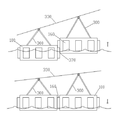
도7은 본 발명의 부력체를 이용한 경사가변형 수상 태양광 발전장치로서, 단위 부력체는 부력체군을 형성하는 과정에서, 행 또는 열로 단위 부력체를 연결하는 구조로, 그 사이 결합부에는 슬라이더(미끄러짐) 또는 힌지구조를 포함하는 구조를 포함하고, 탈락되지 않는 장치를 구비한다.FIG. 7 is a view showing a tilting variable solar photovoltaic power generation apparatus using a buoyant body according to the present invention. In the unit buoyant body, a unit buoyant body is connected with rows or columns in the process of forming a buoyancy body group, Slip) or a hinge structure, and does not fall off.
상기 슬라이더나 힌지구조는 일측 이상의 부력체 내부에 공기압과 물 무게를 가감함으로서 높낮이를 변경할 수 있고, 이 방법으로 태양전지의 각도를 변경하는 경사 가변식 수상태양광 발전장치를 구현할 수 있는 특징이 있다.The slider or the hinge structure is characterized in that it is possible to change the height by increasing or decreasing the air pressure and the weight of the water inside the buoyant body at one side or more and to realize the variable tilting water state power generation device for changing the angle of the solar cell by this method .
또한 행열을 맞춰서 결합된 부력체군에서, 배치된 부력체들의 밸브에는 단독 또는 병렬로 배관을 설치하고, 공기나 물을 동시에 가감할 수 있도록 하는 제어구조를 구비하는 것이 바람직하다.It is also preferable that the buoyancy body group coupled with the rows of the matrices is provided with a control structure for installing the piping in the valves of the buoyant bodies disposed separately or in parallel so that air or water can be simultaneously added or subtracted.
부력체의 상단에 설치된 태양전지 결속부(390)는 힌지구조로서, 부력체들의 높낮이 변화에 따라 태양전지의 기울기를 변화할 수 있도록 구현하는 수상태양광 발전장치 The solar cell coupling unit 390 provided at the upper end of the buoyant body has a hinge structure and is configured to change the slope of the solar cell according to the change in the height of the buoyant bodies.
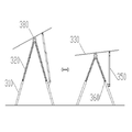
도8은 본 발명의 엑추에이터를 이용한 경사가변형 수상 태양광 발전장치를 도식한 것으로서, 지지구조A(310)와 지지구조B(320)는 큰 원형 또는 사각파이프로 구현되는 것이 바람직하며, 지지구조A는 지지구조B를 내측에 끼워 인출이 가능한 구조로, 지지구조B 보다 내경이 넓고, 엑추에이터(350)가 길어지면서 지지구조B가 지지구조A로부터 이탈하는 구조로 지지구조의 일 측에만 적용하는 방법도 가능하다.FIG. 8 illustrates a tiltable variable solar photovoltaic power generation apparatus using the actuator of the present invention. It is preferable that the
도면에 상세히 표시하지 않은 지지구조의 부분들도 기울기가 바뀌는 부분에 있어서 힌지 구조로 구성된다는 점을 감안한다.The portions of the support structure not shown in detail in the drawing are also configured as a hinge structure in a portion where the inclination is changed.
도9는 본 발명의 태양광 구조물의 경사 가변시 엑추에이터 동작예시도로서, 9 is a diagram illustrating an example of the operation of the actuator when the inclination of the solar photovoltaic structure according to the present invention is changed,
태양전지 지지구조(300)의 일측에 설치되는 엑추에이터(350)와 쐐기(360)구조의 병행으로 사용이 가능하고, 기본적으로는 태양전지를 태양황도에 따라 이동하게 하는 장치로써, 적용하는 방법에 따라서 경사와 방위를 추적 할 수 있다. It is possible to use the solar
상기 엑추에이터는 태양전지 지지구조B(320)에 설치되어 태양 빛과 태양전지가 직각이 될수 있도록 하고, 동작 후에는 풍압으로 인한 파손을 막기 위해 태양전지 지지구조에 구성된 쐐기(360)구조를 통해 고정한다. 쐐기 구조는 기계적 또는 전기적으로 동작하며, 적정한 부분에 구멍을 만들어 쐐기가 강력하게 지지구조A와 지지구조B를 잡아 주는 것이 바람직하다. 엑추에이터는 상기 설명에 국한되지 않고 방법에 따라 다양한 부분에 설치하여 운영이 가능하다.The actuator is installed in the solar cell supporting
도10은 본 발명의 태양광발전장치 제어부 블록도로서, 아래에 기술되는 설명은 일반적인 요소를 기록한 것으로 사용 목적에 따라서 센서는 가감이 가능하다. FIG. 10 is a block diagram of a solar power generator control unit of the present invention. In the following description, general elements are recorded, and the sensor can be added or subtracted according to the purpose of use.
본 발명의 수상태양광 발전장치는 태양의 위치를 추적하는 기능을 구현하기 위해 추적센서(510)과 프로그램적으로 위치를 연산하는 연산부(570)을 포함하고, 강풍에서 태양전지 지지구조(300)을 수평으로 회피하는 기능을 구현하거나, 부력체(100)에 공기를 제거하여 물의 유입을 늘리는 방식으로 수면에 가깝게 또는 수면 아래로 이동할 수 있도록 할 수 있다.The water-state photovoltaic device of the present invention includes a
상기와 같은 목적으로, 수상 태양광 발전장치에는 부력체의 높낮이와 태양전지의 기울기, 부력체군의 방향 등을 제어하는 운영제어시스템(500)을 필요로 하는데, 태양의 위치를 추적하는 태양추적센서(510), 바람의 속도를 파악하는 풍속센서(520), 부력체의 내부의 공기압을 샘플링하는 기압센서(530), 구동이나 바람에 의해 움직인 정도를 파악하는 자이로 센서 등의 동작감지센서(540), 부력체 내부의 물에 양을 측정하는 수위감지센서(550) 등이 구비되는 특징이 있다.For the above-mentioned purposes, the aquamarine solar power generation system requires an
또한 상기의 센서들에서 얻어진 데이터를 취합하는 데이터 수집부(560)와 확보한 데이터를 분석하는 연산부(570), 산출된 결과에 따라 구동부를 동작시키는 동작제어부(600), 동작제어부에 연동되어 태양전지 구조물을 제어하는 엑추에이터 제어부(610), 부력체의 높이를 조절하는 기압제어부(620) 등이 포함하고, 진행상황을 관리자에게 통보하는 통신부(580)와 상황을 저장하는 메모리부(590) 등으로 구성된 발전소 운영제어시스템(500)을 포함한다. A
도11은 본 발명의 수상태양광 발전장치의 측면도로서,11 is a side view of the water-state photovoltaic generation apparatus of the present invention,
단위 부력체에 태양전지를 고정하는데 필요한 태양전지 결속부(390)를 구현하는 방법으로, 기존 제품들이 부력체를 철제 구조물로 고정 지지하고, 그 위에 태양전지를 고정하는 방법을 사용함으로서 설치에 어려움이 많아서 경제적인 손실이 많았다면, 본 발명의 부력체는 결속테이프(200)와 돌기(115) 및 쐐기 방식으로 부력체를 결속함으로서, 기존 제품들의 금속 고정장치로 인한 부력체의 손상 문제를 최소화 할 수 있다.The method of embodying the solar cell coupling unit 390 for fixing the solar cell to the unit buoyant body is difficult because the conventional products use a method of fixing the buoyant body by the iron structure and fixing the solar cell thereon. The buoyant body of the present invention binds the
태양전지 결속부(390)은 부력체의 상단에 함침(녹여 붙이거나 내측에 삽입되는 형태를 의미함) 되어 부력체의 일부가 되는 것이 바람직하며, 간단하게는 부력체에 붙인 후에 결속테이프(200)로 상단을 붙여서 부력체 구조와 일체화 시키는 방법이 바람직하다.It is preferable that the solar cell binding portion 390 be impregnated (melted or inserted into the inside) at the upper end of the buoyant member and become a part of the buoyant member. ) Is attached to the buoyant structure so as to be integrated with the buoyant structure.
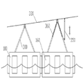
태양전지는 전방과 후방으로 한 개 이상씩의 태양전지 결속부(390)에 의해 고정되며, 기본적으로 4개 이상을 설치하는 것이 바람직하고, 결속부는 힌지구조로 구현하여 태양의 위치를 따라 태양전지의 기울기를 변경하는 기능을 구현하고, 바람의 피해가 우려되면 완전히 뉘여서 후방 태양전지 결속부 브라켓과 직결할수 있는 구조를 구현하는 것이 바람직하다.The solar cell is fixed by one or more solar cell coupling parts 390 forward and backward. Basically, four or more solar cells are preferably installed, and the coupling part is implemented by a hinge structure, It is desirable to realize a structure that can be directly connected to the rear solar cell binding portion bracket by completely diffusing when the wind damage is concerned.
후방 태양전지 결속부(390)은 힌지 구조와 3개의 고정부 "A, B, C"(410,420,430)로 구현되며, 지지부품 "A"의 길이는 "B"와 "C"의 합보다 짧게 구현하여, 태양의 고도가 가장 높은 여름철에 태양전지의 기울기가 가장 낮도록 "A"(410)를 기준으로 태양전지와 부력체를 연결하고, 겨울철에는 "B"와 "C"를 일렬로 배열하고 "A"로 구부려 지지 않도록 두 지지부품을 고정하는 방식으로 태양전지의 기울기를 가변하여 태양광 발전 효율을 향상시키는 특징이 있다. The back solar cell coupling unit 390 is implemented with a hinge structure and three fixing units "A, B, C" 410, 420 and 430. The length of the supporting member "A" is shorter than the sum of "B" A solar cell and buoyant body are connected based on the "A" (410) so that the slope of the solar cell is the lowest in the summer when the sun's altitude is highest, and "B" and "C" And the solar cell power generation efficiency is improved by changing the inclination of the solar cell by fixing the two supporting parts so as not to be bent to " A ".
도12는 본 발명의 활용 예시도로서, 12 is an explanatory diagram illustrating an application of the present invention,
부력체의 외벽을 연장하거나, 상단에 추가적인 격실을 설치하는 형태의 변형된 부력체로서 어업용이나 연구용 등 다양한 목적으로 사용이 가능하다. 추가적인 비용이 들지만 결속의 범위가 넓어지고 활용도가 넓어지는 장점이 있다.It is a deformed buoyant body in which the outer wall of the buoyant body is extended or an additional compartment is provided at the upper end. It can be used for various purposes such as fishing and research. There is an additional cost, but it has the advantage of broadening the scope of the bond and extending the utilization.
상기와 같이 구현되는 본 발명의 수상태양광 발전장치는 저렴한 생산단가와 안정적인 부유, 대단위 구조물의 설치가 가능해지고, 태풍이나 돌풍, 파도와 같은 자연적인 영향에서 비교적 자유롭게 운전이 가능해지는 장점이 있다. The water-state photovoltaic generation apparatus of the present invention, which is implemented as described above, is advantageous in that it can be installed at a low production cost, stable floating, and large-scale structure, and can be relatively freely operated under natural influences such as typhoons, winds, and waves.
100 : 부력체 105 : 수면
110 : 격벽 115 : 격실
120 : 밸브
130 : 폐쇄형 하부커버
135 : 하부커버 결속부
140 : 개폐형 하부커버
150 : 커버개폐부
160 : 결합돌기
170 : 개폐형 상부커버
200 : 결속테이프
210 : 외부 고정부
300 : 태양전지 지지구조
310 : 지지구조A
320 : 지지구조B
330 : 태양전지 거치대
350 : 엑추에이터 360 : 쐐기
370 : 슬라이더
380 : 지지대 결속부
390 : 태양전지 결속부
400 : 태양전지
410 : 고정부 A 420 : 고정부 B
430 : 고정부 C 450 : AB결합부
500 : 운영제어시스템
510 : 태양추적센서
520 : 풍속센서
530 : 기압센서
540 : 동작감지센서
550 : 수위감지센서
560 : 데이터수집부
570 : 연산부
580 : 통신부
590 : 메모리부
600 : 동작제어부
610 : 엑추에이터 제어부
620 : 기압제어부100: Buoyant body 105: Sleeping
110: partition 115: compartment
120: Valve
130: closed bottom cover
135: Lower cover binding part
140: openable bottom cover
150: Cover opening /
160: engaging projection
170: Openable top cover
200: binding tape
210:
300: solar cell supporting structure
310: support structure A
320: support structure B
330: Solar cell holder
350: Actuator 360: Wedge
370: Slider
380:
390: Solar cell binding part
400: Solar cell
410: stationary station A 420: stationary station B
430: fixed portion C 450: AB coupling portion
500: Operation control system
510: Solar tracking sensor
520: wind speed sensor
530: Pressure sensor
540: Motion detection sensor
550: Water level sensor
560:
570:
580:
590:
600:
610: Actuator control unit
620:
Claims (16)
하부의 전체 또는 일부가 개방되어 물의 유입이 가능한 개방된 구조,
하중에 의해 수면 아래로 잠수되어, 물이 부력체 내부 공기가 외부로 유출되는 것을 차단하는 구조,
부력체의 내측은 필요에 따라 한 개 또는 이상의 공간으로 분리하는 격벽(110)을 포함하는 구조,
부력체의 상단 또는 일부에 태양전지(400)를 설치할 수 있는 결합구조를 포함하는 수상태양광 발전장치
The material of the buoyant body (100) is a nonmetal or metal such as plastic that can maintain watertightness,
An open structure in which all or a part of the lower part is opened and water can be introduced,
A structure in which the water is submerged under the water by the load to block the air in the buoyant body from flowing out to the outside,
The inner side of the buoyant body includes a partition 110 separating into one or more spaces as needed,
A water-state positive photovoltaic power generating device including a coupling structure capable of installing a solar cell (400) on the top or a part of the buoyant body
부력체에는 수면과 가까운 부분에 쉽게 개폐가 가능한 볼밸브 또는 체크밸브 등의 밸브(120)구조를 포함하고,
환경이나 목적에 따라 공기를 필요한 만큼 필요한 위치에 주입하여 높이를 조절할 수 있는 파이프나 경로 등의 수단을 포함하는 수상 태양광 발전장치
In claim 1,
The buoyant body includes a valve 120 structure such as a ball valve or a check valve that can be easily opened and closed at a portion close to the water surface,
A water photovoltaic power generation apparatus including a means such as a pipe or a path capable of controlling the height by injecting air to a necessary position according to the environment or purpose
부력체의 하부에는 판 형태 또는 일부가 개방된 하부커버(130)를 설치하여,
물의 이동을 제한할 수 있는 구조를 포함하는 수상태양광 발전장치
The method according to any one of claims 1 to 2,
A lower cover 130 having a plate shape or a part of which is open is provided in the lower portion of the buoyant body,
A water-state photovoltaic power generating device including a structure capable of restricting movement of water
부력체의 외부에는,
내측보다 외측이 넓은 사다리꼴 형태로 서로 끼워지면 빠지기 어려운 형태
또는 같은 목적을 수행할 수 있는 형태의 돌기를 한 개 이상 포함하는 구조,
부력체들의 돌기들을 서로 끼워 맞추는 방식으로 군락을 형성하는 수상 태양광 발전장치
In claim 1,
On the outside of the buoyant body,
It is a form that is difficult to escape if it fits together in a trapezoidal shape with a wider outer side than the inner side.
Or a structure including one or more protrusions of a shape capable of performing the same purpose,
A water photovoltaic device that forms a community by fitting the protrusions of the buoyancy bodies together
부력체의 외측에는 내측을 향해서, ㄷ, H 등의 찬넬이나 물체가 끼워질 수 있는 홈을 가지는 구조,
다수의 부유물을 일렬로 배치하고, 돌기를 끼워 맞춘 후, 일정 길이에 맞춰 ㄷ 또는 H 형태의 구조물을 행이나 열로 끼워 넣고, 부력체 군의 둘레를 ㅁ 형태로 돌아서 고정하는 구조,
상화전후 유동을 제한하는 수단을 포함하는 수상 태양광 발전장치
In paragraphs 1 and 4,
A structure having a channel such as C, H or the like or a groove into which an object can be fitted, toward the inside toward the outside of the buoyancy body,
A structure in which a plurality of floats are arranged in a line, the projections are fitted, a structure of a c or H type structure is fitted in a row or a row to fit a certain length, and a periphery of the buoyancy body group is turned and fixed in a ㅁ-
An aquarium photovoltaic device comprising means for limiting flow before and after imagery
부력체들을 고정하는 수단으로서,
부력체와 같은 소재 또는 접착제로 일체화 할 수 있는 소재로서,
길고 넓은 면 구조 또는 테이프 형상으로 결속테이프(200)를 만들고,
부력체의 표면에 붙여 다수의 부력체를 일체화 하는 방식의 결합력 향상 방법을 포함하는 수상 태양광 발전장치
The method according to any one of claims 1 to 5,
As means for securing buoyancy bodies,
As a material that can be integrated with a material such as a buoyant body or an adhesive,
The binding tape 200 is made in a long and wide surface structure or a tape shape,
An aqueous photovoltaic device comprising a bonding force improving method in which a plurality of buoyant bodies are bonded to a surface of a buoyant body
부력체를 연결하는 결합테이프의 안쪽에는 접착제와 함께 결속테이프(200)의 인장력을 높이고, 절단이 어렵게 하는 소재를 끼우거나 접착하여 절단반발력을 향상시키는 구조의 결합테이프
In claim 6,
A bonding tape having a structure for enhancing the tensile force of the binding tape 200 together with an adhesive on the inner side of the binding tape connecting the buoyant body and for improving the cutting repulsive force by sandwiching or adhering a material which makes it difficult to cut
단위 부력체는 부력체군을 형성하는 과정에서,
행, 열 또는 단위 부력체들 사이에 끼워지는 결합부에 슬라이더(미끄러짐)(450) 또는 힌지구조를 포함하는 구조를 포함하고,
부력체 내부의 공기압과 물 무게를 가감하여 높낮이를 변경하는 방법으로 태양전지의 각도를 변경하는 방식의 경사 가변식 수상태양광 발전장치
In claim 1,
In the process of forming buoyancy group,
Includes a structure including a slider (slip) 450 or a hinge structure in a coupling portion that fits between row, column or unit buoyancy bodies,
A variable gradient water-state photovoltaic power generator in which the angle of the solar cell is changed by changing the elevation by adding air pressure and water weight inside the buoyant body
행열을 맞춰서 결합된 부력체군에서,
배치된 부력체들의 밸브에는 단독 또는 병렬로 배관을 설치하고,
공기나 물을 동시에 가감할 수 있도록 하는 제어구조를 포함하는 수상태양광 발전장치
In claims 1 to 2 to 8,
In the buoyancy group,
The valves of the disposed buoyancy bodies may be provided with a single pipe or a pipe in parallel,
And a control structure for allowing air or water to be simultaneously added or subtracted from the water-
부력체의 상단에 설치된 태양전지 지지결속부(390), 지지대결속부(380)는 힌지구조로서, 부력체들의 높낮이 변화에 따라 태양전지의 기울기를 변화할 수 있도록 하는 수상태양광 발전장치
The method according to any one of claims 1 to 8 to 9,
The solar cell support binding portion 390 and the support band binding portion 380 provided at the upper end of the buoyant member are hinge structures that can change the slope of the solar cell in accordance with the change of the height of the buoyancy members,
부력체 상단의 태양전지 결속부는 풍압에 충분히 견고한 소재나 구조로서,
태양전지와 결합되는 부분을 제외하고는 부력체에 결합테이프로 접착하여 일체화 시키는 방식의 태양전지 고정구조를 포함하는 수상태양광 발전장치.
The method according to any one of claims 1 to 10,
The solar cell binding part on the top of the buoyant body is a material or structure sufficiently strong in wind pressure,
And a solar cell fixing structure in which the solar cell is adhered to the buoyant body by a bonding tape except for a portion to be combined with the solar cell.
단위 부력체 또는 다수의 부력체를 연결한 부력체군에서,
소수 또는 다수의 태양전지를 한 태양전지 구조물에 설치하고, 태양의 이동에 따라 경사를 가변하는 경우,
태양전지 구조물의 일부 지지구조물에는 높이를 조절하는 엑추에이터를 포함하고,
일부의 지지구조물에는 기계적 또는 전기적으로 쐐기를 입출 할 수 있도록 하는 고정수단을 포함하는 높낮이가 조절되는 수상태양광 발전장치
The method according to any one of claims 1 to 10,
In a buoyancy body group in which a unit buoyancy body or a plurality of buoyancy bodies are connected,
When a small number or a large number of solar cells are installed in a solar cell structure and the inclination is varied according to the movement of the sun,
Some supporting structures of the solar cell structure include an actuator for adjusting the height,
Some supporting structures are provided with a height-adjustable water-state photovoltaic power generating device, including fixing means for mechanical or electrical wedge entry
부력체를 이용한 수상 태양광 발전장치의 높낮이와 태양전지의 기울기, 부력체군의 방향 등을 제어하는 운영제어시스템(500),
태양의 위치를 추적하는 태양추적센서(510), 바람의 속도를 파악하는 풍속센서(520),
부력체의 내부의 공기압을 샘플링하는 기압센서(530), 구동이나 바람에 의해 움직인 정도를 파악하는 자이로 센서 등의 동작감지센서(540), 부력체 내부의 물의 양을 측정하는 수위감지센서(550),
이상의 센서에서 얻어진 데이터를 취합하는 데이터 수집부(560)
확보한 데이터를 분석하는 연산부(570), 산출된 결과에 따라 구동부를 동작시키는 동작제어부(600), 동작제어부에 연동되어 태양전지 구조물을 제어하는 엑추에이터 제어부(610), 부력체의 높이를 조절하는 기압제어부(620)
진행상황을 관리자에게 통보하는 통신부(580)와 상황을 저장하는 메모리부(590) 등으로 구성된 추적식 수상 태양광 발전소 운영제어시스템를 포함하는 수상태양광 발전장치
The method according to any one of claims 1 to 8,
An operation control system 500 for controlling the height of the aquarium photovoltaic device using the buoyant body, the inclination of the solar cell, and the direction of the buoyancy group,
A solar tracking sensor 510 for tracking the position of the sun, an air velocity sensor 520 for sensing the velocity of the wind,
An air pressure sensor 530 for sampling the air pressure inside the buoyant body, a motion detection sensor 540 such as a gyro sensor for detecting the degree of movement by wind or wind, a water level sensor for measuring the amount of water in the buoyant body 550),
The data collecting unit 560 collects data obtained from the above sensors,
An operation control unit 600 for operating the driving unit according to the calculated result, an actuator control unit 610 for controlling the solar cell structure in conjunction with the operation control unit, a control unit 610 for controlling the height of the buoyant body, The air pressure controller 620,
A water-state photovoltaic power generation apparatus including a tracking unit 580 including a communication unit 580 for notifying an administrator of the progress and a memory unit 590 for storing a situation,
단위 부력체에 태양전지를 고정하는 하는 방법으로,
태양전지의 전후로는 한 개 이상씩의 태양전지 결속부를 설치하고,
각 태양전지 결속부(390)는 힌지구조로 구현하고,
뒤쪽 힌지 구조는 충분한 강성의 소재로 만들어진 "고정부 A, B, C"(410,420,430) 3개의 지지부품으로 구현하되,
"A"의 길이는 "B"와 "C"의 합보다 짧게 구현하고,
태양의 고도가 가장 높은 여름철에 태양전지의 기울기가 가장 낮도록 "A"(410)를 기준으로 태양전지와 부력체를 연결하고, 겨울철에는 "B"와 "C"를 일렬로 배열하고 구부러지지 않도록 "A"로 두 지지부품을 고정하는 방식의 태양전지 기울기 가변방식의 수상 태양광 발전장치.
In claim 1,
As a method for fixing a solar cell to a unit buoyant body,
One or more solar cell binding portions are provided before and after the solar cell,
Each solar cell coupling unit 390 is implemented as a hinge structure,
The rear hinge structure is implemented with three support parts of " Fixed A, B, C " (410,420,430) made of a sufficiently rigid material,
The length of "A" is shorter than the sum of "B" and "C"
Solar cell and buoyant body are connected based on "A" (410) so that the slope of the solar cell is the lowest in the summer when the sun is highest. In winter, "B" and "C" A "solar cell tilt-variable solar photovoltaic system in which two supporting parts are fixed with" A ".
부력체를 다중으로 연결하고, 일측에 가두리 어업용 그물을 설치한 구조,
태풍이나 적조 시에 공기를 최소로 하고 물에 양을 최대로 하여, 하중에 의해 수면 아래 일정 깊이까지 내려가서, 바람에 의한 파손을 방지하거나 적조로부터 물고기를 폐사 전에 방류할 수 있는 기능을 포함하는 수상구조물.
In claim 1,
A structure in which a plurality of buoyant bodies are connected and a net for cage fishing is installed on one side,
It includes the function of minimizing air in typhoons and red tides, maximizing the amount of water, lowering to a certain depth below the water surface by the load, preventing wind damage, and discharging fish from the red tide Water structures.
부력체의 다양한 변형의 예제로서, 부력체의 외벽을 상부로 연장한 구조,
상부를 개방형 또는 일부 개방형으로 변형되어 적용되는 구조와
상기 서술한 결합구조와 운영방식 등으로 변형되어 운영되는 수상 태양광 발전장치.Paragraphs 1 to 15
Examples of various variations of the buoyant body include a structure in which the outer wall of the buoyant body is extended upward,
A structure in which the upper portion is deformed into an open type or a part of an open type, and
The solar photovoltaic power generation apparatus is modified and operated by the above-described coupling structure and operating method.
Priority Applications (1)
| Application Number | Priority Date | Filing Date | Title |
|---|---|---|---|
| KR1020170133664A KR20190042135A (en) | 2017-10-14 | 2017-10-14 | Floating solar power system with hight adjustment pontoons |
Applications Claiming Priority (1)
| Application Number | Priority Date | Filing Date | Title |
|---|---|---|---|
| KR1020170133664A KR20190042135A (en) | 2017-10-14 | 2017-10-14 | Floating solar power system with hight adjustment pontoons |
Publications (1)
| Publication Number | Publication Date |
|---|---|
| KR20190042135A true KR20190042135A (en) | 2019-04-24 |
Family
ID=66282387
Family Applications (1)
| Application Number | Title | Priority Date | Filing Date |
|---|---|---|---|
| KR1020170133664A KR20190042135A (en) | 2017-10-14 | 2017-10-14 | Floating solar power system with hight adjustment pontoons |
Country Status (1)
| Country | Link |
|---|---|
| KR (1) | KR20190042135A (en) |
Cited By (7)
| Publication number | Priority date | Publication date | Assignee | Title |
|---|---|---|---|---|
| KR20210000489A (en) * | 2019-06-25 | 2021-01-05 | 주식회사 포스코 | Floating solar power generating apparatus |
| WO2021080077A1 (en) * | 2019-10-21 | 2021-04-29 | 차내윤 | Offshore floating structure |
| KR102331201B1 (en) * | 2020-08-26 | 2021-12-01 | 주식회사 세이브에너지 | Floating structure for solar power using composite material and manufacturing method thereof |
| KR102333362B1 (en) * | 2021-04-26 | 2021-12-03 | 남부에너지 주식회사 | Solar generating apparatus |
| US11290054B2 (en) * | 2019-08-02 | 2022-03-29 | Semi Led Co., Ltd. | Floating photovoltaic panel installation structure and buoyancy body for installation of floating photovoltaic panel |
| CN114835213A (en) * | 2022-05-26 | 2022-08-02 | 西安西热水务环保有限公司 | Immersed type electrostatic water treatment device |
| CN116002867A (en) * | 2023-02-21 | 2023-04-25 | 东营市海洋发展研究院 | Ecological floating plate for water area ecological environment treatment and restoration |
Citations (3)
| Publication number | Priority date | Publication date | Assignee | Title |
|---|---|---|---|---|
| KR100887723B1 (en) | 2008-05-30 | 2009-03-12 | 백흥기 | Collecting apparatus for sun-beam |
| KR101629872B1 (en) | 2016-01-18 | 2016-06-14 | (주) 태광 | The light of the sun Buoys and aquatic photovoltaic power generation apparatus and the installation method |
| KR101642430B1 (en) | 2015-01-27 | 2016-07-25 | 전인석 | Store management system using beacon system |
-
2017
- 2017-10-14 KR KR1020170133664A patent/KR20190042135A/en unknown
Patent Citations (3)
| Publication number | Priority date | Publication date | Assignee | Title |
|---|---|---|---|---|
| KR100887723B1 (en) | 2008-05-30 | 2009-03-12 | 백흥기 | Collecting apparatus for sun-beam |
| KR101642430B1 (en) | 2015-01-27 | 2016-07-25 | 전인석 | Store management system using beacon system |
| KR101629872B1 (en) | 2016-01-18 | 2016-06-14 | (주) 태광 | The light of the sun Buoys and aquatic photovoltaic power generation apparatus and the installation method |
Cited By (8)
| Publication number | Priority date | Publication date | Assignee | Title |
|---|---|---|---|---|
| KR20210000489A (en) * | 2019-06-25 | 2021-01-05 | 주식회사 포스코 | Floating solar power generating apparatus |
| US11290054B2 (en) * | 2019-08-02 | 2022-03-29 | Semi Led Co., Ltd. | Floating photovoltaic panel installation structure and buoyancy body for installation of floating photovoltaic panel |
| WO2021080077A1 (en) * | 2019-10-21 | 2021-04-29 | 차내윤 | Offshore floating structure |
| KR102331201B1 (en) * | 2020-08-26 | 2021-12-01 | 주식회사 세이브에너지 | Floating structure for solar power using composite material and manufacturing method thereof |
| KR102333362B1 (en) * | 2021-04-26 | 2021-12-03 | 남부에너지 주식회사 | Solar generating apparatus |
| CN114835213A (en) * | 2022-05-26 | 2022-08-02 | 西安西热水务环保有限公司 | Immersed type electrostatic water treatment device |
| CN116002867A (en) * | 2023-02-21 | 2023-04-25 | 东营市海洋发展研究院 | Ecological floating plate for water area ecological environment treatment and restoration |
| CN116002867B (en) * | 2023-02-21 | 2023-06-09 | 东营市海洋发展研究院 | Ecological floating plate for water area ecological environment treatment and restoration |
Similar Documents
| Publication | Publication Date | Title |
|---|---|---|
| KR20190042135A (en) | Floating solar power system with hight adjustment pontoons | |
| CA1321514C (en) | Spar buoy pen system | |
| US4377352A (en) | Self-actuating water containment barrier | |
| KR20060094018A (en) | Wave power station | |
| JP6305940B2 (en) | Self-operating flood waterproof wall | |
| EP2919581A1 (en) | Offshore aquaculture installation | |
| CN203256676U (en) | Floating breakwater giving consideration to fishing and aquaculture | |
| JP6122550B2 (en) | Multi-function mounting device for tidal current generator and method of using the same | |
| US20130038063A1 (en) | Apparatus and method for inhibiting the formation of tropical cyclones | |
| KR20130098586A (en) | Buoyant type solar power generation apparatus | |
| KR20200056649A (en) | Device for floating debris collection using tide and method thereof | |
| AU2011200741A1 (en) | Mooring System for Offshore Fish Production | |
| CN113854214A (en) | Mariculture net cage structure based on semi-submersible offshore wind power foundation | |
| CN212035467U (en) | Intelligent deep-sea aquaculture net cage | |
| KR20190138167A (en) | Floating solar generator and transition fit type pontoon | |
| CN114852273A (en) | Steel frame buoy type offshore photovoltaic platform | |
| CN111134067A (en) | Intelligent deep-sea aquaculture net cage | |
| KR101402763B1 (en) | Rolling pitching damper for aquatic facilities | |
| JP6750170B1 (en) | Deep-sea transport device for sea surface water by waves | |
| CN212581601U (en) | Box-type ecological floating island lake bay lake flow improving device | |
| KR101192552B1 (en) | Floating body for wave power generation and plant for wave power generation utilizing the body | |
| KR102200448B1 (en) | Floating structure for aquaculture. | |
| CN211079883U (en) | Suspension bridge in water | |
| KR102185915B1 (en) | Construction structure of floating type structure on water surface | |
| CN111573846A (en) | Box type ecological floating island lake bay lake flow improvement device and application |