KR20190032605A - Polarizer - Google Patents
Polarizer Download PDFInfo
- Publication number
- KR20190032605A KR20190032605A KR1020197007171A KR20197007171A KR20190032605A KR 20190032605 A KR20190032605 A KR 20190032605A KR 1020197007171 A KR1020197007171 A KR 1020197007171A KR 20197007171 A KR20197007171 A KR 20197007171A KR 20190032605 A KR20190032605 A KR 20190032605A
- Authority
- KR
- South Korea
- Prior art keywords
- layer
- polarizer
- coated
- mixture
- stretching
- Prior art date
Links
Images


Classifications
-
- G—PHYSICS
- G02—OPTICS
- G02B—OPTICAL ELEMENTS, SYSTEMS OR APPARATUS
- G02B5/00—Optical elements other than lenses
- G02B5/30—Polarising elements
- G02B5/3025—Polarisers, i.e. arrangements capable of producing a definite output polarisation state from an unpolarised input state
- G02B5/3033—Polarisers, i.e. arrangements capable of producing a definite output polarisation state from an unpolarised input state in the form of a thin sheet or foil, e.g. Polaroid
- G02B5/3041—Polarisers, i.e. arrangements capable of producing a definite output polarisation state from an unpolarised input state in the form of a thin sheet or foil, e.g. Polaroid comprising multiple thin layers, e.g. multilayer stacks
- G02B5/305—Polarisers, i.e. arrangements capable of producing a definite output polarisation state from an unpolarised input state in the form of a thin sheet or foil, e.g. Polaroid comprising multiple thin layers, e.g. multilayer stacks including organic materials, e.g. polymeric layers
-
- B—PERFORMING OPERATIONS; TRANSPORTING
- B29—WORKING OF PLASTICS; WORKING OF SUBSTANCES IN A PLASTIC STATE IN GENERAL
- B29D—PRODUCING PARTICULAR ARTICLES FROM PLASTICS OR FROM SUBSTANCES IN A PLASTIC STATE
- B29D11/00—Producing optical elements, e.g. lenses or prisms
- B29D11/00634—Production of filters
- B29D11/00644—Production of filters polarizing
-
- B—PERFORMING OPERATIONS; TRANSPORTING
- B32—LAYERED PRODUCTS
- B32B—LAYERED PRODUCTS, i.e. PRODUCTS BUILT-UP OF STRATA OF FLAT OR NON-FLAT, e.g. CELLULAR OR HONEYCOMB, FORM
- B32B27/00—Layered products comprising a layer of synthetic resin
- B32B27/06—Layered products comprising a layer of synthetic resin as the main or only constituent of a layer, which is next to another layer of the same or of a different material
- B32B27/08—Layered products comprising a layer of synthetic resin as the main or only constituent of a layer, which is next to another layer of the same or of a different material of synthetic resin
-
- B—PERFORMING OPERATIONS; TRANSPORTING
- B32—LAYERED PRODUCTS
- B32B—LAYERED PRODUCTS, i.e. PRODUCTS BUILT-UP OF STRATA OF FLAT OR NON-FLAT, e.g. CELLULAR OR HONEYCOMB, FORM
- B32B7/00—Layered products characterised by the relation between layers; Layered products characterised by the relative orientation of features between layers, or by the relative values of a measurable parameter between layers, i.e. products comprising layers having different physical, chemical or physicochemical properties; Layered products characterised by the interconnection of layers
- B32B7/02—Physical, chemical or physicochemical properties
-
- B—PERFORMING OPERATIONS; TRANSPORTING
- B29—WORKING OF PLASTICS; WORKING OF SUBSTANCES IN A PLASTIC STATE IN GENERAL
- B29K—INDEXING SCHEME ASSOCIATED WITH SUBCLASSES B29B, B29C OR B29D, RELATING TO MOULDING MATERIALS OR TO MATERIALS FOR MOULDS, REINFORCEMENTS, FILLERS OR PREFORMED PARTS, e.g. INSERTS
- B29K2029/00—Use of polyvinylalcohols, polyvinylethers, polyvinylaldehydes, polyvinylketones or polyvinylketals or derivatives thereof as moulding material
- B29K2029/04—PVOH, i.e. polyvinyl alcohol
-
- B—PERFORMING OPERATIONS; TRANSPORTING
- B29—WORKING OF PLASTICS; WORKING OF SUBSTANCES IN A PLASTIC STATE IN GENERAL
- B29K—INDEXING SCHEME ASSOCIATED WITH SUBCLASSES B29B, B29C OR B29D, RELATING TO MOULDING MATERIALS OR TO MATERIALS FOR MOULDS, REINFORCEMENTS, FILLERS OR PREFORMED PARTS, e.g. INSERTS
- B29K2995/00—Properties of moulding materials, reinforcements, fillers, preformed parts or moulds
- B29K2995/0018—Properties of moulding materials, reinforcements, fillers, preformed parts or moulds having particular optical properties, e.g. fluorescent or phosphorescent
Abstract
배향된 중합체 제1 층을 포함하는 편광기가 기재된다. 배향된 중합체 제1 층은 폴리비닐 알코올 및 가교결합제의 혼합물로부터 제조가능하며, 가교결합제는 폴리비닐 알코올과 가교결합제의 총 중량을 기준으로 5 내지 40 중량%로 혼합물에 포함된다. 배향된 중합체 제1 층은, U=(1/MDDR-1)/(TDDR1 /2 -1)에 대하여, U는 적어도 0.85라는 점에서 실질적으로 단축 연신된 층이며, 여기서 MDDR은 기계 방향 연신비이고, TDDR은 횡방향 연신비이다.Polarizers comprising an oriented polymer first layer are described. The oriented polymer first layer can be prepared from a mixture of polyvinyl alcohol and a cross-linking agent, and the cross-linking agent is included in the mixture in an amount of 5 to 40 wt% based on the total weight of the polyvinyl alcohol and the cross-linking agent. The oriented polymer layer is a first, U = (1 / MDDR- 1) / (TDDR 1/2 -1) with respect to, U is the substantially uniaxially stretched layer in that it is at least 0.85, wherein MDDR is the machine direction draw ratio And TDDR is the transverse stretching ratio.
Description
흡수 편광기는, 폴리비닐 알코올 층을 연신하여 그 층 내의 폴리비닐 알코올 분자를 정렬시키고, 정렬된 층을 요오드로 염색함으로써 제조될 수 있다. 그러한 편광기는 다양한 디스플레이 응용에 사용되어 왔다.The absorption polarizer can be prepared by stretching a polyvinyl alcohol layer to align the polyvinyl alcohol molecules in the layer and dyeing the aligned layer with iodine. Such polarizers have been used in a variety of display applications.
본 발명의 일부 태양에서, 배향된 중합체 제1 층을 포함하는 편광기가 제공된다. 배향된 중합체 제1 층은 폴리비닐 알코올 및 가교결합제를 함유하는 혼합물로부터 제조가능하며, 가교결합제는 폴리비닐 알코올과 가교결합제의 총 중량을 기준으로 5 내지 40 중량%로 혼합물에 포함된다. 배향된 중합체 제1 층은, U=(1/MDDR-1)/(TDDR1/2 -1)에 대하여, U는 적어도 0.85라는 점에서 실질적으로 단축 연신된 층이며, 여기서 MDDR은 기계 방향 연신비이고, TDDR은 횡방향 연신비이다.In some aspects of the present invention, a polariser is provided that includes an oriented polymer first layer. The oriented polymer first layer can be prepared from a mixture containing polyvinyl alcohol and a crosslinking agent, wherein the crosslinking agent is included in the mixture in an amount of 5 to 40% by weight based on the total weight of the polyvinyl alcohol and the crosslinking agent. The oriented polymer first layer is a substantially uniaxially stretched layer in that U is at least 0.85 for U = (1 / MDDR-1) / (TDDR 1/2 -1), wherein MDDR is the machine direction stretch ratio And TDDR is the transverse stretching ratio.
본 발명의 일부 태양에서, 배향된 중합체 제1 층을 갖는 편광기의 제조 방법이 제공된다. 본 방법은 용매 중에 폴리비닐 알코올 및 가교결합제의 혼합물을 형성하는 단계; 혼합물을 제2 층 상에 코팅하는 단계; 혼합물을 건조시켜 용매를 제거함으로써, 건조된 코팅을 형성하는 단계; 코팅된 제2 층을 연신하여 건조된 코팅을 배향시킴으로써, 배향된 중합체 제1 층을 형성하는 단계를 포함한다. 혼합물에 포함된 가교결합제의 중량을 가교결합제의 중량과 폴리비닐 알코올의 중량의 합으로 나눈 값은 0.05 내지 0.3의 범위이다. 코팅된 제2 층을 연신하는 단계는, 코팅된 제2 층을 기계 방향을 따라 연신기 내에서 이송하면서, 코팅된 제2 층의 대향하는 에지 부분을 유지하고, 발산 비선형 경로를 따라 대향하는 에지 부분을 이동시킴으로써 연신기 내에서 코팅된 제2 층을 연신하는 단계를 포함한다.In some aspects of the present invention, a method of making a polarizer having an oriented polymeric first layer is provided. The method includes forming a mixture of polyvinyl alcohol and a crosslinking agent in a solvent; Coating the mixture on the second layer; Drying the mixture to remove the solvent to form a dried coating; And stretching the coated second layer to orient the dried coating to form an oriented polymer first layer. The weight of the crosslinking agent contained in the mixture divided by the sum of the weight of the crosslinking agent and the weight of the polyvinyl alcohol is in the range of 0.05 to 0.3. The step of stretching the coated second layer is carried out by maintaining the opposing edge portions of the coated second layer while transferring the coated second layer in the machine direction along the machine direction, And stretching the coated second layer in the stretching machine by moving the portion.
도 1은 편광기의 단면도이다.
도 2는 배향된 중합체 층을 형성하기 위한 공정의 예시이다.
도 3은 연신기의 개략 평면도이다.
도 4 및 도 5는 디스플레이의 개략 단면도이다.
도 6은 중합체 다층 광학 필름의 단면도이다.
도 7 내지 도 9는 다양한 편광기에 대한 투과 스펙트럼의 도표이다.1 is a cross-sectional view of a polarizer.
Figure 2 is an illustration of a process for forming an oriented polymer layer.
3 is a schematic plan view of a stretching machine.
Figures 4 and 5 are schematic cross-sectional views of the display.
6 is a cross-sectional view of a polymer multilayer optical film.
7 to 9 are graphs of transmission spectra for various polarizers.
하기 설명에서, 본 명세서의 일부를 형성하고 다양한 실시 형태들이 예시로서 도시되어 있는 첨부 도면을 참조한다. 도면은 반드시 축척대로 그려진 것은 아니다. 다른 실시 형태들이 고려되며 본 발명의 범주 또는 사상으로부터 벗어남이 없이 이루어질 수 있다는 것이 이해되어야 한다. 따라서, 하기의 상세한 설명은 제한적 의미로 해석되어서는 안 된다.In the following description, reference is made to the accompanying drawings, which form a part hereof and in which is shown by way of illustration various embodiments. The drawings are not necessarily drawn to scale. It is to be understood that other embodiments may be contemplated and may be made without departing from the scope or spirit of the invention. The following detailed description is, therefore, not to be taken in a limiting sense.
흡수 편광기는, 폴리비닐 알코올 (PVA 또는 PVOH) 층을 연신하여 그 층 내의 PVA 분자를 정렬시키고, 정렬된 층을 요오드로 염색함으로써 통상적으로 제조된다. 요오드 분자는 배향된 PVA 분자에 맞추어 정렬된다. 정렬 방향을 따라 편광된 (즉, 편광기의 차단축을 따라 편광된) 입사광은 요오드에 의해 흡수되거나 부분적으로 흡수되고, 직교 방향을 따라 편광된 (즉, 편광기의 통과축을 따라 편광된) 입사광은 편광기를 통해 투과되거나 부분적으로 투과된다.An absorption polarizer is typically prepared by stretching a polyvinyl alcohol (PVA or PVOH) layer to align the PVA molecules in the layer and dyeing the aligned layer with iodine. The iodine molecules are aligned to the oriented PVA molecules. Incident light that is polarized along the alignment direction (i.e., polarized along the blocking axis of the polarizer) is absorbed or partially absorbed by iodine and incident light that is polarized along the orthogonal direction (i.e., polarized along the axis of passage of the polarizer) Lt; / RTI >
다른 유형의 편광기는, 차단축을 따라 편광된 광에 대해서는 반사를 제공하고 차단축에 직교하는 통과축을 따라 편광된 광을 투과시키도록 구성된 교번하는 중합체 층들을 포함하는 중합체 다층 광학 필름이다. 그러한 필름은, 교번하는 제1 및 제2 유형의 중합체 층의 스택을 압출하고, 압출된 스택을 단축으로 또는 대략 단축으로 연신하여 제1 및 제2 유형의 중합체 층 중 적어도 하나를 배향시킴으로써 제조될 수 있으며, 이는, 예를 들어 미국 특허 제5,882,774호 (존자(Jonza) 등)에 전반적으로 기재된 바와 같다. 예를 들어, 미국 특허 제6,916,440호 (잭슨(Jackson) 등)에 기재된 것들과 같은 포물선형 연신기 또는 텐터 기계가 반사 편광기 내의 복굴절 층들의 단축 배향의 정도를 개선하는 데 사용되어 왔다.Another type of polariser is a polymer multilayer optical film comprising alternating polymer layers configured to provide reflection for light polarized along the blocking axis and to transmit polarized light along a pass axis orthogonal to the minor axis. Such films may be prepared by extruding a stack of alternating first and second types of polymeric layers and stretching the extruded stack uniaxially or substantially uniaxially to orient at least one of the first and second types of polymeric layers , As is generally described, for example, in U.S. Patent No. 5,882,774 (Jonza et al.). For example, parabolic stretcher or tenter machines such as those described in U.S. Patent No. 6,916,440 (Jackson et al.) Have been used to improve the degree of uniaxial orientation of birefringent layers within a reflective polarizer.
일부 경우에, 디스플레이 응용에서 흡수 편광기 및 반사 편광기 둘 모두를 포함하는 것이 바람직할 수 있다. 반사 편광기는, 예를 들어 액정 디스플레이 응용에서 편광 재순환을 위해 사용될 수 있고, 흡수 편광기는 흡광 효율(extinction efficiency)을 개선하기 위해 반사 편광기에 추가될 수 있다. 흡수 편광기와 반사 편광기의 통합은 미국 특허 제6,096,375호 (오더커크(Ouderkirk) 등), 제6,697,195호 (웨버(Weber) 등), 제7,826,009호 (웨버 등), 및 제6,111,697호 (카우쉬(Kausch) 등)에 기재되어 있으며, 이들 각각은 본 발명과 모순되지 않는 한에 있어서 본 명세서에 참고로 포함된다.In some cases, it may be desirable to include both an absorption polarizer and a reflection polarizer in a display application. Reflective polarizers can be used, for example, for polarization recycling in liquid crystal display applications, and absorption polarizers can be added to reflective polarizers to improve extinction efficiency. The incorporation of an absorption polarizer and a reflective polarizer is described in U. S. Patent No. 6,096, 375 (Ouderkirk et al), 6,697,195 (Weber et al.), 7,826,009 (Weber et al.), And 6,111,697 (Kausch ), Etc., each of which is incorporated herein by reference insofar as it is not inconsistent with the present invention.
본 발명에 따르면, PVA 중에 적합한 가교결합제를 포함하는 것으로부터 제조된 개질된 PVA 층을 포함하는 편광기는, 개질된 PVA 층이 통상적인 선형 텐터를 사용하여 달성가능한 것보다 더 높은 정도의 단축 배향으로 배향되는 경우 개선된 광학 특성을 제공하는 것으로 밝혀졌다. 특히, 흡수 편광기를 형성하기 위하여, PVA 층 내에 적합한 가교결합제를 포함하는 것과 대향하는 에지 부분들을 (예를 들어, 층을 실질적으로 단축 배향시키기 위하여 포물선형 텐터를 사용하여) 발산 비선형 경로를 따라 이동시킴으로써 층을 연신하는 것의 조합은, 관심 파장 범위 내에 있고 차단축을 따라 편광되는 수직 입사광의 낮은 최소 투과율 (예를 들어, 0.1% 미만)과 관심 파장 범위 내에 있고 통과축을 따라 편광되는 수직 입사광의 높은 최대 투과율 (예를 들어, 75% 초과)을 동시에 달성하는 것으로 밝혀졌다. 관심 파장 범위는, 예를 들어 가시 범위 (400 nm 내지 700 nm)일 수 있거나 또는 540 nm 내지 640 nm일 수 있다. 일부 실시 형태에서, 흡수 편광기는 적어도 99.8% 또는 적어도 99.9%의 편광 효율 (PE)을 갖는다. 편광 효율은 수학식 1에 의해 주어진다:According to the present invention, polarizers comprising a modified PVA layer prepared from comprising a suitable crosslinking agent in PVA are preferred because the modified PVA layer has a higher degree of uniaxial orientation than can be achieved using conventional linear tentering And provide improved optical properties when oriented. In particular, in order to form an absorbing polarizer, it is necessary to move the edge portions opposite to those containing a suitable cross-linking agent in the PVA layer (e.g., using a parabolic tenter to substantially uniaxially orient the layer) (E.g., less than 0.1%) of normal incidence light that is within the wavelength range of interest and that is polarized along the blocking axis, and a high maximum of vertical incidence light that is within the wavelength range of interest and is polarized along the pass axis. (E. G., Greater than 75%). ≪ / RTI > The wavelength range of interest may be, for example, the visible range (400 nm to 700 nm) or may be from 540 nm to 640 nm. In some embodiments, the absorption polarizer has a polarization efficiency (PE) of at least 99.8% or at least 99.9%. The polarization efficiency is given by equation (1): < EMI ID =
[수학식 1][Equation 1]
![]()
![]()
여기서, Max Pass 는 관심 파장 범위에 걸친 수직 입사에서의 최대 통과 상태 투과율이고, Min Block 은 관심 파장 범위에 걸친 수직 입사에서의 최소 차단 상태 투과율이다.Here, Max Pass is the maximum passing state transmittance at normal incidence over the wavelength range of interest, and Min Block is the minimum blocking state transmittance at normal incidence over the wavelength range of interest.
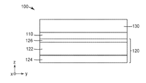
도 1은 기재(120) 상에 배치된, 배향된 중합체 제1 층(110)을 포함하는 편광기(100)의 개략 단면도이다. 기재(120)는, 예를 들어 단일 중합체 층일 수 있는 제2 층(122)을 포함하거나, 예를 들어 중합체 다층 반사 편광기일 수 있는 중합체 다층 광학 필름일 수 있다. 예시된 실시 형태에서, 기재(120)는 추가 층(124)을 추가로 포함하며, 이는, 예를 들어 지연기 (예를 들어, 1/4 파장 지연기)일 수 있다. 대안적인 실시 형태에서, 추가 층(124)은 생략되고, 일부 경우에 제2 층(122)은 지연기이다. 선택적으로 생략될 수 있는 프라이머(126)가, 배향된 중합체 제1 층(110)과 제2 층(122) 사이에 배치된다. 프라이머(126)는 기재(120)의 층으로 간주될 수 있거나, 또는 배향된 중합체 제1 층(110)과 기재 사이의 층으로 간주될 수 있다. 제2 층(122) 반대편의 배향된 중합체 제1 층(110)에 인접하여 제3 층(130)이 배치된다. 일부 실시 형태에서, 제3 층(130)은 보호 층, 접착제 층, 지연기, 또는 이들의 조합이거나 또는 이를 포함한다. 대안적인 실시 형태에서, 제3 층(130)은 생략된다.Figure 1 is a schematic cross-sectional view of a
일부 실시 형태에서, 제2 층(122) 및 제3 층(130) 중 하나 또는 둘 모두는 광학적으로 투명한 중합체 층, 또는 복수의 광학적으로 투명한 중합체 층이다. 적합한 중합체 층은, 예를 들어 폴리에틸렌 테레프탈레이트 (PET), 글리콜-개질된 PET (PETg), 폴리에틸렌 나프탈레이트 (PEN), 다른 폴리에스테르 또는 코폴리에스테르, 폴리카르보네이트, 및 이들의 공중합체로부터 제조된 것들을 포함한다.In some embodiments, one or both of the
지연기가 편광기 내에 층으로서 포함되는 실시 형태에서, 지연기는 관심 파장의 1/4과 대략 동일한 평면내 지연을 갖는 1/4 파장 지연기일 수 있다. 관심 파장은, 예를 들어 가시 범위 (400 nm 내지 700 nm) 내의 임의의 파장일 수 있고 550 nm일 수 있다. 달리 명시되지 않는 한, 1/4 파장 지연기는 가시광 파장의 1/4의 평면내 지연을 갖는 지연기를 지칭한다. 일부 실시 형태에서, 100 nm 내지 175 nm, 또는 125 nm 내지 150 nm의 평면내 지연을 갖는 1/4 파장 지연기가 편광기에 사용된다. 일부 실시 형태에서, 가시광 파장의 1/4 이외의 평면내 지연을 갖는 지연기가 사용된다. 예를 들어, 1/2 파장 지연기 또는 다른 지연기가 사용될 수 있다. 일부 실시 형태에서, 100 nm 내지 350 nm, 또는 200 nm 내지 350 nm의 평면내 지연을 갖는 지연기가 편광기에 사용된다. 층의 평면내 지연은 관심 파장에서의 2개의 직교하는 평면내 굴절률 사이의 차이의 절대값 x 층의 두께를 지칭한다.In embodiments where the retarder is included as a layer in the polarizer, the retarder may be a quarter wavelength retarder with an in-plane retardation approximately equal to one quarter of the wavelength of interest. The wavelength of interest may be, for example, any wavelength within the visible range (400 nm to 700 nm) and may be 550 nm. Unless otherwise specified, a quarter wave retarder refers to a retarder having an in-plane retardation of one quarter of the wavelength of visible light. In some embodiments, a 1/4 wavelength retarder with an in-plane retardation of 100 nm to 175 nm, or 125 nm to 150 nm is used in the polarizer. In some embodiments, a retarder having an in-plane delay other than 1/4 of the visible light wavelength is used. For example, a half-wave retarder or other retarder may be used. In some embodiments, a retarder having an in-plane retardation of 100 nm to 350 nm, or 200 nm to 350 nm, is used in the polariser. The in-plane retardation of a layer refers to the absolute value of the difference between two orthogonal in-plane refractive indices at the wavelength of interest x the thickness of the layer.
배향된 중합체 제1 층(110)은 이색성 재료, 예컨대 요오드, 또는 소정의 파장 범위에서 흡수를 제공하는 다른 염료 또는 안료를 포함한다. 파장 범위는 사용되는 염료 및/또는 안료의 유형에 좌우된다. 디스플레이 응용에서는, 파장 범위가 가시 범위 (400 nm 내지 700 nm) 또는 가시 범위의 적어도 실질적인 부분 (예를 들어, 450 nm 내지 650 nm)을 포함할 것이 전형적으로 요구된다. 예를 들어, 요오드 분자는 배향된 중합체 제1 층(110) 내의 폴리비닐 알코올 분자에 맞추어 정렬되고, 이에 따라 배향 방향을 따라 편광된 광에 대해서는 강한 흡수를 제공하고, 한편 직교 편광의 광에 대해서는 투과를 가능하게 한다. 예를 들어, 도 1의 x-y-z 좌표계를 참조하면, x-축은 배향된 중합체 제1 층(110)에 대한 차단축일 수 있고, 제2 층(122)이 반사 편광기인 실시 형태에서는 또한 제2 층(122)의 차단축일 수 있다. 유사하게, y-축은 배향된 중합체 제1 층(110)에 대한 통과축일 수 있고, 제2 층(122)이 반사 편광기인 실시 형태에서는 또한 제2 층(122)의 통과축일 수 있다.The oriented polymer
배향된 중합체 제1 층(110)은 폴리비닐 알코올 및 가교결합제를 포함하는 혼합물로부터 제조가능하다. 일부 실시 형태에서, 가교결합제는 폴리비닐 알코올과 가교결합제의 총 중량을 기준으로 5 내지 40 중량%, 또는 5 내지 30 중량%로 혼합물에 포함된다. 일부 실시 형태에서, 폴리비닐 알코올과 가교결합제의 혼합물이 용매 중에 형성되고, 이것이 제2 층 상에 코팅된다. 일부 실시 형태에서, 폴리비닐 알코올의 혼합물은 용매 중에서 10 내지 20 중량% 고형물로 희석된다. 일부 실시 형태에서, 혼합물에 포함된 가교결합제의 중량을 가교결합제의 중량과 폴리비닐 알코올의 중량의 합으로 나눈 값은 0.05 내지 0.3의 범위이다. 일부 실시 형태에서, 가교결합제는 하나 이상의 포름알데하이드-부가물, 예컨대 멜라민-포름알데하이드 및 우레아-포름알데하이드를 포함한다.The oriented polymer
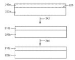
도 2는 배향된 중합체 제1 층(210c)을 형성하기 위한 공정을 예시한다. 배향된 중합체 제1 층(210c)은 제2 층(220a) 상에 혼합물(210a)을 코팅하는 단계; 혼합물을 건조시켜 (단계(242)) 용매를 제거하고, 그럼으로써 제2 층(222b) 상에 건조된 코팅(210b) (이는 제2 층(222a)과 동일할 수 있거나 또는 건조 공정에 의해 변경될 (예를 들어, 열적으로 완화될) 수 있음)을 형성하는 단계; 코팅된 제2 층(222b)을 실질적으로 단축 연신하여 (단계(244)) 건조된 코팅(210b)을 배향시키고, 그럼으로써 제2 층(222c) (이는, 층의 두께가 연신 공정에 의해 일반적으로 축소될 것임을 제외하고는 제2 층(222b)과 동일할 수 있거나, 또는 연신 공정에 의해 변경될 (예를 들어, 배향될) 수 있음) 상에 배향된 중합체 제1 층(210c)을 형성하는 단계에 의해 제조가능하다.Figure 2 illustrates a process for forming an oriented polymer
일부 실시 형태에서, 혼합물은, 예를 들어 슬라이드 다이 코팅기를 사용하여 단일 단계로 프라이머와 함께 코팅된다. 다른 실시 형태에서는, 프라이머가 제2 층(220a)의 주 표면(225) 상에 코팅되고, 이어서 혼합물이 제2 층(220a)의 프라이밍된 표면 상에 코팅된다. 또 다른 실시 형태에서, 프라이머는 사용되지 않는다. 일부 실시 형태에서, 제2 층(220a)의 주 표면(225)은 프라이머를 코팅하기 전에 표면 처리되고, 일부 실시 형태에서, 제2 층(220a)의 주 표면(225)은 표면 처리되고 혼합물은 표면 처리된 표면 상에 직접 코팅된다. 적합한 표면 처리에는, 예를 들어 플라즈마 또는 코로나 처리가 포함된다.In some embodiments, the mixture is coated with the primer in a single step using, for example, a slide die coater. In another embodiment, a primer is coated on the
건조 단계(242)는, 예를 들어 25 ℃ 내지 180 ℃, 또는 50 ℃ 내지 150 ℃, 또는 70 ℃ 내지 120 ℃, 또는 25 ℃ 내지 180 ℃ 범위의 온도에서 수행될 수 있다. 일부 실시 형태에서, 혼합물은 연신 전에 5분 이하 동안 150 ℃ 초과의 온도에 있다. 일부 실시 형태에서, 건조된 폴리비닐 알코올 층은 연신 전에 두께가 1.5 내지 15 마이크로미터이다. 일부 실시 형태에서, 프라이머 층은 연신 전에 두께가 0.45 내지 3 마이크로미터이다. 연신 단계(244)는, 예를 들어 25 ℃ 내지 180 ℃, 또는 50 ℃ 내지 180 ℃, 또는 110 ℃ 내지 180 ℃ 범위의 온도에서 수행될 수 있다. 일부 실시 형태에서, 폴리비닐 알코올 층은 연신 단계 후에 두께가 0.5 내지 5 마이크로미터이다. 일부 실시 형태에서, 프라이머 층은 연신 단계 후에 두께가 0.15 내지 1 마이크로미터이다.The drying
배향된 중합체 제1 층(110 또는 210c)은 흡수 염료, 예컨대 요오드로 착색되어 흡수 편광기를 제공할 수 있다. 배향된 폴리비닐 알코올 층을 요오드로 착색시켜 흡수 편광기를 제조하는 것은 당업계에 공지되어 있으며, 전반적으로 미국 특허 제4,166,871호 (슐러(Shuler))에 기재되어 있다. 배향된 층의 착색에 대한 대안으로서, 폴리비닐 알코올 사슬에 맞추어 정렬될 수 있는 염료 또는 안료가 코팅 및 연신 전에 혼합물에 첨가되어 배향된 층을 형성할 수 있다. 일부 실시 형태에서, 이색성 염료가 혼합물에 첨가되어 원하는 파장 범위에서 흡수를 제공한다.The oriented polymer
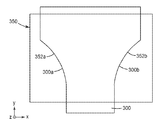
도 3은 코팅된 제2 층(300)을 기계 방향 (도 3에서의 x-y-z 좌표계를 참조하면, y-방향)을 따라 연신기 내에서 이송하면서, 코팅된 제2 층(300)의 대향하는 에지 부분(300a, 300b)을 유지하고, 발산 비선형 경로(352a, 352b)를 따라 대향하는 에지 부분(300a, 300b)을 이동시킴으로써 연신기(350) 내에서 코팅된 제2 층(300)을 연신하기 위한 연신기(350)의 개략도이다. 일부 실시 형태에서, 배향된 중합체 제1 층(110)은, U=(1/MDDR-1)/(TDDR1/2 -1)에 대하여, U는 적어도 0.85라는 점에서 실질적으로 단축 연신된 층이며, 여기서 MDDR은 기계 방향 (y-방향) 연신비이고, TDDR은 횡방향 (x-방향) 연신비이다. 일부 실시 형태에서, 비선형 경로(352a, 352b)는 포물선형이다. 필름을 실질적으로 단축 연신하도록 구성된 연신기에 대한 추가의 상세 사항은 미국 특허 제6,916,440호 (잭슨 등)에 기재되어 있으며, 이는 본 발명과 모순되지 않는 한에 있어서 본 명세서에 참고로 포함된다. 일부 실시 형태에서, 층은 110 ℃ 내지 180 ℃, 또는 130 ℃ 내지 170 ℃ 범위의 온도에서 3 내지 8, 또는 4 내지 7 범위의 MDDR로 연신된다.Figure 3 shows a cross-sectional view of a
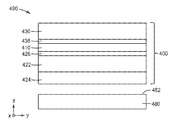
본 발명의 편광기는 다양한 디스플레이 응용에 유용하다. 도 4는 제1 편광기(400) 및 디스플레이 패널(480)을 포함하는 디스플레이(490)의 개략 단면도이다. 디스플레이(490)는 본 명세서의 어딘가 다른 곳에서 추가로 기재되는 바와 같은 추가 편광기를 포함할 수 있다. 디스플레이(490)는 도 4의 x-y-z 좌표계를 참조하면, 디스플레이(490)의 z-방향에 대체로 위치된 관찰자에게 광을 제공하도록 구성된다. 디스플레이 패널(480)은 광 출력면(482)을 갖고, 제1 편광기(400)는 광 출력면(482)에 인접하게 그리고 그것과 대면하여 배치된다. 일부 실시 형태에서, 디스플레이 패널(480)은 유기 발광 다이오드 (OLED) 디스플레이 패널이고, 일부 실시 형태에서, 디스플레이 패널(480)은 액정 디스플레이 (LCD) 패널이다.The polarizer of the present invention is useful for various display applications. 4 is a schematic cross-sectional view of a
편광기(100)에 상응할 수 있는 제1 편광기(400)는 배향된 중합체 제1 층(410), 제2 층(422) - 이는, 예를 들어 반사 편광기일 수 있음 - 을 포함하고, 추가 층(424) - 이는, 예를 들어 지연기 (예를 들어, 1/4 파장 지연기)일 수 있음 - 을 추가로 포함한다. 대안적인 실시 형태에서, 추가 층(424)은 생략되고, 일부 경우에 제2 층(422)은 지연기이다. 선택적인 프라이머(426)가 배향된 중합체 제1 층(410)과 제2 층(422) 사이에 배치된다. 제2 층(422) 반대편의 배향된 중합체 제1 층(410)에 인접하여 제3 층(430)이 배치된다. 선택적인 프라이머(436)가 배향된 중합체 제1 층(410)과 제3 층(430) 사이에 배치된다. 일부 실시 형태에서, 제3 층(430)은 보호 층, 접착제 층, 지연기, 또는 이들의 조합이거나 또는 이를 포함한다. 대안적인 실시 형태에서, 제3 층(430)은 생략된다.The
도 5는 제1 편광기(500a), 제2 편광기(500b), 및 디스플레이 패널(580)을 포함하는 디스플레이(590)의 개략 단면도이다. 디스플레이(590)는 도 5의 x-y-z 좌표계를 참조하면, 디스플레이(590)의 z-방향에 대체로 위치된 관찰자에게 광을 제공하도록 구성된다. 디스플레이 패널(580)은 광 출력면(582)을 갖고, 제1 편광기(500a)는 광 출력면(582)에 인접하게 그리고 그것과 대면하여 배치된다. 디스플레이 패널(580)은 또한 광 입력면(584)을 갖고, 제2 편광기(500b)는 광 입력면(584)에 인접하게 그리고 그것과 대면하여 배치된다. 제1 편광기(500a)는 배향된 중합체 제1 층(510a), 제2 층(522a) 및 제3 층(530a)을 포함한다. 제2 편광기(500b)는 배향된 중합체 제1 층(510b), 제2 층(522b) 및 제3 층(530b) 및 제4 층(528b)을 포함한다. 층들(522a, 530, 522b, 530b, 528b) 중 하나 이상이 선택적으로 생략될 수 있다. 프라이머 층은 도 5에 도시된 임의의 2개의 바로 인접한 층들 사이에 배치될 수 있다. 일부 실시 형태에서, 제3 층(530a 및/또는 530b)은 보호 층, 접착제 층, 지연기, 또는 이들의 조합이다. 일부 실시 형태에서, 제2 층(522a)은 반사 편광기 또는 지연기이다. 일부 실시 형태에서, 제2 층(522a)은 1/4 파장 지연기이다. 일부 실시 형태에서, 제2 층(522a)은 반사 편광기 및 지연기 둘 모두를 포함한다. 일부 실시 형태에서, 제2 층(522b)은 반사 편광기이고, 제4 층(528b)은 지연기이며, 이는 1/4 파장 지연기일 수 있다. 일부 실시 형태에서, 디스플레이 패널(580)은 투과형 공간 광 변조기, 예컨대 LCD 패널이다.5 is a schematic cross-sectional view of a
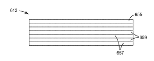
배향된 중합체 제1 층은 제2 층 상에 배치될 수 있으며, 제2 층은 중합체 다층 광학 필름일 수 있다. 도 6은 복수의 제2 층(659)과 교번하는 복수의 제1 층(657)을 포함하는 중합체 다층 광학 필름(613)의 단면도이다. 일부 실시 형태에서, 중합체 다층 광학 필름(613)은 도 6에 도시된 바와 같이 외부 층일 수 있거나 또는 교번하는 층들(657, 659) 중 하나일 수 있는 적어도 하나의 이색성 층(655)을 포함한다. 하나 이상의 이색성 층을 포함하는 중합체 다층 광학 필름이 미국 특허 제6,096,375호 (오더커크 등), 제6,697,195호 (웨버 등), 제7,826,009호 (웨버 등), 및 제6,111,697호 (카우쉬 등)에 추가로 기재되어 있다.The oriented polymer first layer may be disposed on the second layer, and the second layer may be a polymer multilayer optical film. 6 is a cross-sectional view of a polymer multilayer
다음은 본 발명의 예시적인 실시 형태의 목록이다.The following is a list of exemplary embodiments of the present invention.
실시 형태 1은 편광기로서, 상기 편광기는 배향된 중합체 제1 층을 포함하며, 배향된 중합체 제1 층은 폴리비닐 알코올 및 가교결합제를 포함하는 혼합물로부터 제조가능하며, 가교결합제는 폴리비닐 알코올과 가교결합제의 총 중량을 기준으로 5 내지 40 중량%로 혼합물에 포함되고, 배향된 중합체 제1 층은, U=(1/MDDR-1)/(TDDR1/2 -1)에 대하여, U는 적어도 0.85라는 점에서 실질적으로 단축 연신된 층이며, 여기서 MDDR은 기계 방향 연신비이고, TDDR은 횡방향 연신비이다.
실시 형태 2는, 실시 형태 1에 있어서, 배향된 중합체 제1 층은 이색성 재료를 포함하는, 편광기이다.
실시 형태 3은, 실시 형태 2에 있어서, 이색성 재료는 요오드를 포함하는, 편광기이다.
실시 형태 4는, 실시 형태 1에 있어서, 제2 층을 추가로 포함하며, 배향된 중합체 제1 층은 제2 층 상에 배치되는, 편광기이다.
실시 형태 5는, 실시 형태 4에 있어서, 제3 층을 추가로 포함하며, 제3 층은 제2 층 반대편의 배향된 중합체 제1 층에 인접한, 편광기이다.
실시 형태 6은, 실시 형태 5에 있어서, 제3 층은 보호 층, 접착제 층, 지연기, 또는 이들의 조합을 포함하는, 편광기이다.Embodiment 6 is a polarizer according to
실시 형태 7은, 실시 형태 5에 있어서, 제2 층은 중합체 다층 광학 필름을 포함하는, 편광기이다.
실시 형태 8은, 실시 형태 4에 있어서, 제2 층은 중합체 다층 광학 필름을 포함하는, 편광기이다.Embodiment 8 is a polarizer according to
실시 형태 9는, 실시 형태 8에 있어서, 중합체 다층 광학 필름은 반사 편광기를 포함하는, 편광기이다.Embodiment 9 In Embodiment 8, in Embodiment 8, the polymer multilayer optical film is a polarizer including a reflective polarizer.
실시 형태 10은, 실시 형태 9에 있어서, 배향된 중합체 제1 층의 차단축이 반사 편광기의 차단축에 맞추어 정렬되는, 편광기이다.
실시 형태 11은, 실시 형태 8에 있어서, 중합체 다층 광학 필름은 적어도 하나의 이색성 층을 포함하는, 편광기이다.Embodiment 11 is the polarizer according to Embodiment 8, wherein the polymer multilayer optical film includes at least one dichroic layer.
실시 형태 12는, 실시 형태 8에 있어서, 지연기가, 배향된 중합체 제1 층 반대편의 중합체 다층 광학 필름 상에 배치되는, 편광기이다.Embodiment 12 is a polarizer in Embodiment 8, in which a retarder is disposed on the polymer multilayer optical film opposite to the oriented polymer first layer.
실시 형태 13은, 실시 형태 12에 있어서, 지연기는 1/4 파장 지연기인, 편광기이다.Embodiment 13 In Embodiment 13, in Embodiment 12, the retarder is a polarizer, which is a quarter wavelength retarder.
실시 형태 14는, 실시 형태 8에 있어서, 지연기가 중합체 다층 광학 필름 반대편의 배향된 중합체 제1 층 상에 배치되는, 편광기이다.Embodiment 14 is the polarizer in Embodiment 8, wherein the retarder is disposed on the oriented polymer first layer opposite the polymer multilayer optical film.
실시 형태 15는, 실시 형태 8에 있어서, 지연기가, 배향된 중합체 제1 층과 중합체 다층 광학 필름 사이에 배치되는, 편광기이다.Embodiment 15 is a polarizer in Embodiment 8 wherein a retarder is disposed between the oriented first polymer layer and the polymer multilayer optical film.
실시 형태 16은, 실시 형태 4에 있어서, 배향된 중합체 제1 층과 제2 층 사이에 배치되는 프라이머를 추가로 포함하는, 편광기이다.Embodiment 16 is a polarizer according to
실시 형태 17은, 실시 형태 1에 있어서, 지연기가, 배향된 중합체 제1 층 상에 배치되는, 편광기이다.Embodiment 17 is a polarizer in
실시 형태 18은, 실시 형태 17에 있어서, 지연기는 1/4 파장 지연기인, 편광기이다.Embodiment 18 In Embodiment 17, the retarder is a polarizer, which is a quarter wavelength retarder.
실시 형태 19a는, 실시 형태 1 내지 실시 형태 18 중 어느 하나에 따른 제1 편광기를 포함하는, 디스플레이이다.Embodiment 19a is a display comprising a first polarizer according to any one of
실시 형태 19는, 실시 형태 1에 따른 제1 편광기를 포함하는, 디스플레이이다.Embodiment 19 is a display including the first polarizer according to
실시 형태 20은, 실시 형태 19에 있어서, 광 출력면을 갖는 디스플레이 패널을 추가로 포함하며, 제1 편광기는 광 출력면에 인접하게 그리고 그것과 대면하여 배치되는, 디스플레이이다.
실시 형태 21은, 실시 형태 20에 있어서, 제1 편광기는 배향된 중합체 제1 층과 디스플레이 패널 사이에 배치되는 지연기를 추가로 포함하는, 디스플레이이다.Embodiment 21 is a display according to
실시 형태 22는, 실시 형태 21에 있어서, 지연기는 1/4 파장 지연기인, 디스플레이이다.Embodiment 22 In Embodiment 21, in Embodiment 21, the retarder is a display that is a quarter wavelength retarder.
실시 형태 23은, 실시 형태 21에 있어서, 디스플레이 패널은 유기 발광 디스플레이 패널인, 디스플레이이다.Embodiment 23 In Embodiment 21, the display panel is a display, which is an organic light emitting display panel.
실시 형태 24는, 실시 형태 20에 있어서, 제1 편광기는 배향된 중합체 제1 층과 디스플레이 패널 사이에 배치되는 제2 층을 포함하는, 디스플레이이다.Embodiment 24 is a display according to
실시 형태 25는, 실시 형태 24에 있어서, 제2 층은 중합체 다층 광학 필름을 포함하는, 디스플레이이다.
실시 형태 26은, 실시 형태 25에 있어서, 중합체 다층 광학 필름은 반사 편광기를 포함하는, 디스플레이이다.Embodiment 26 is the display according to
실시 형태 27은, 실시 형태 25에 있어서, 제1 편광기는 지연기를 추가로 포함하는, 디스플레이이다.Embodiment 27 is a display according to
실시 형태 28은, 실시 형태 27에 있어서, 중합체 다층 광학 필름은 배향된 중합체 제1 층과 지연기 사이에 배치되는, 디스플레이이다.Embodiment 28 is the display according to Embodiment 27, wherein the polymer multilayer optical film is disposed between the oriented polymer first layer and the retarder.
실시 형태 29는, 실시 형태 27에 있어서, 지연기는, 중합체 다층 광학 필름과 배향된 중합체 제1 층 사이에 배치되는, 디스플레이이다.Embodiment 29 is the display according to Embodiment 27, wherein the retarder is disposed between the polymer multilayer optical film and the oriented polymer first layer.
실시 형태 30은, 실시 형태 27에 있어서, 배향된 중합체 제1 층은, 중합체 다층 광학 필름과 지연기 사이에 배치되는, 디스플레이이다.
실시 형태 31은, 실시 형태 27에 있어서, 지연기는 1/4 파장 지연기인, 디스플레이이다.Embodiment 31 is a display in Embodiment 27, wherein the retarder is a quarter wavelength retarder.
실시 형태 32는, 실시 형태 20에 있어서, 제1 편광기는 제3 층을 추가로 포함하며, 배향된 중합체 제1 층은 제3 층과 디스플레이 패널 사이에 배치되는, 디스플레이이다.Embodiment 32. The Embodiment 32 is the display according to
실시 형태 33은, 실시 형태 20에 있어서, 디스플레이 패널의 광 입력면에 인접하게 그리고 그것과 대면하여 배치되는, 실시 형태 1에 따른 제2 편광기를 추가로 포함하는, 디스플레이이다.Embodiment 33 is a display according to
실시 형태 34는, 실시 형태 33에 있어서, 제2 편광기는 제2 층 및 제2 층과 디스플레이 패널 사이에 배치되는 제3 층을 포함하고, 제2 편광기의 배향된 중합체 제1 층은 제2 편광기의 제2 층과 제3 층 사이에 배치되는, 디스플레이이다.Embodiment 34 is the liquid crystal display according to Embodiment 33, wherein the second polarizer comprises a second layer and a third layer disposed between the second layer and the display panel, and the oriented polymer first layer of the second polarizer comprises a second polarizer Is disposed between the second and third layers of the display.
실시 형태 35는, 실시 형태 34에 있어서, 제2 편광기의 제2 층은 중합체 다층 광학 필름을 포함하는, 디스플레이이다.Embodiment 35. A display according to Embodiment 34, wherein the second layer of the second polarizer comprises a polymer multilayer optical film.
실시 형태 36은, 실시 형태 35에 있어서, 중합체 다층 광학 필름은 반사 편광기를 포함하는, 디스플레이이다.Embodiment 36: In Embodiment 35, the polymer multilayer optical film is a display including a reflective polarizer.
실시 형태 37은, 실시 형태 34에 있어서, 제2 편광기의 제3 층은 보호 층, 접착제 층, 지연기, 또는 이들의 조합을 포함하는, 디스플레이이다.Embodiment 37: A display according to Embodiment 34, wherein the third layer of the second polarizer comprises a protective layer, an adhesive layer, a retarder, or a combination thereof.
실시 형태 38은, 실시 형태 33에 있어서, 제2 편광기는 중합체 다층 광학 필름을 포함하며, 제2 편광기의 배향된 중합체 제1 층은 디스플레이 패널과 중합체 다층 광학 필름 사이에 배치되는, 디스플레이이다.Embodiment 38 is the display according to Embodiment 33, wherein the second polarizer comprises a polymer multilayer optical film, and the oriented polymer first layer of the second polarizer is disposed between the display panel and the polymer multilayer optical film.
실시 형태 39는, 실시 형태 38에 있어서, 제2 편광기는 제2 편광기의 배향된 중합체 제1 층 반대편의 중합체 다층 광학 필름 상에 배치되는 지연기를 추가로 포함하는, 디스플레이이다.Embodiment 39. The polymer composition of embodiment 39, wherein the second polarizer is a display further comprising a retarder disposed on the polymer multilayer optical film opposite the oriented polymer first layer of the second polarizer.
실시 형태 40은, 실시 형태 39에 있어서, 지연기는 1/4 파장 지연기인, 디스플레이이다.Embodiment 40: In Embodiment 39, the retarder is a display, which is a quarter wavelength retarder.
실시 형태 41은, 실시 형태 39에 있어서, 중합체 다층 광학 필름은 반사 편광기를 포함하는, 디스플레이이다.Embodiment 41: In Embodiment 39, the polymer multilayer optical film is a display including a reflective polarizer.
실시 형태 42는, 실시 형태 33에 있어서, 제1 편광기는 디스플레이 패널과 제1 편광기의 배향된 중합체 제1 층 사이에 배치되는 제2 층을 포함하는, 디스플레이이다.Embodiment 42. The display device according to Embodiment 33, wherein the first polarizer comprises a display panel and a second layer disposed between the oriented polymer first layer of the first polarizer.
실시 형태 43은, 실시 형태 42에 있어서, 제1 편광기의 제2 층은 중합체 다층 광학 필름 및 지연기 중 적어도 하나를 포함하는, 디스플레이이다.Embodiment 43: A display according to embodiment 42, wherein the second layer of the first polarizer comprises at least one of a polymer multilayer optical film and a retarder.
실시 형태 44는, 실시 형태 33에 있어서, 디스플레이 패널은 액정 디스플레이 패널인, 디스플레이이다.Embodiment 44. A display device according to Embodiment 33, wherein the display panel is a liquid crystal display panel.
실시 형태 45는, 실시 형태 19에 있어서, 광 입력면을 갖는 디스플레이 패널을 추가로 포함하며, 제1 편광기는 광 입력면에 인접하게 그리고 그것과 대면하여 배치되는, 디스플레이이다.Embodiment 45 In Embodiment 19, the display device according to Embodiment 19 further includes a display panel having a light input surface, wherein the first polarizer is disposed adjacent to and facing the light input surface.
실시 형태 46은, 실시 형태 1에 있어서, 가교결합제는 하나 이상의 포름알데하이드-부가물을 포함하는, 편광기이다.Embodiment 46 is the polarizer according to
실시 형태 47은, 실시 형태 1에 있어서, 가교결합제는 멜라민-포름알데하이드를 포함하고, 5 내지 30 중량%로 혼합물에 포함되는, 편광기이다.Embodiment 47 is the polarizer according to
실시 형태 48은, 실시 형태 1에 있어서, 가교결합제는 우레아-포름알데하이드를 포함하고, 5 내지 30 중량%로 혼합물에 포함되는, 편광기이다.Embodiment 48 is a polarizer according to
실시 형태 49는, 실시 형태 1에 있어서, 배향된 중합체 제1 층은 540 nm 내지 640 nm의 파장 범위에 걸친 최소 투과율이 차단축을 따라 편광된 수직 입사광에 대해 0.1% 미만이고, 540 nm 내지 640 nm의 파장 범위에 걸친 최대 투과율이 차단축에 직교하는 통과축을 따라 편광된 수직 입사광에 대해 적어도 75%인, 편광기이다.Embodiment 49 is Embodiment 49 wherein, in
실시 형태 49b는, 실시 형태 46 내지 실시 형태 48 중 어느 하나에 따른 제1 편광기를 포함하는, 디스플레이이다.Embodiment 49b is a display comprising a first polarizer according to any of embodiments 46-48.
실시 형태 50은 배향된 중합체 제1 층을 포함하는 편광기의 제조 방법으로서, 상기 방법은
용매 중에 폴리비닐 알코올 및 가교결합제의 혼합물을 형성하는 단계 - 혼합물에 포함된 가교결합제의 중량을 가교결합제의 중량과 폴리비닐 알코올의 중량의 합으로 나눈 값은 0.05 내지 0.3의 범위임 -;Forming a mixture of a polyvinyl alcohol and a crosslinking agent in a solvent, wherein the weight of the crosslinking agent contained in the mixture divided by the sum of the weight of the crosslinking agent and the weight of the polyvinyl alcohol is in the range of 0.05 to 0.3;
혼합물을 제2 층 상에 코팅하는 단계;Coating the mixture on the second layer;
혼합물을 건조시켜 용매를 제거함으로써, 건조된 코팅을 형성하는 단계;Drying the mixture to remove the solvent to form a dried coating;
코팅된 제2 층을 연신하여 건조된 코팅을 배향시킴으로써, 배향된 중합체 제1 층을 형성하는 단계를 포함하며,Stretching the coated second layer to orient the dried coating to form an oriented polymeric first layer,
코팅된 제2 층을 연신하는 단계는, 코팅된 제2 층을 기계 방향을 따라 연신기 내에서 이송하면서, 코팅된 제2 층의 대향하는 에지 부분을 유지하고, 발산 비선형 경로를 따라 대향하는 에지 부분을 이동시킴으로써 연신기 내에서 코팅된 제2 층을 연신하는 단계를 포함한다.The step of stretching the coated second layer is carried out by maintaining the opposing edge portions of the coated second layer while transferring the coated second layer in the machine direction along the machine direction, And stretching the coated second layer in the stretching machine by moving the portion.
실시 형태 51은, 실시 형태 50에 있어서, 비선형 경로는 포물선형 경로인, 방법이다.Embodiment 51 is a method according to
실시 형태 52는, 실시 형태 50에 있어서, 연신하는 단계는, 코팅된 제2 층을 MDDR의 연신비로 기계 방향으로 연신하고, 코팅된 제2 층을 TDDR의 연신비로 횡방향으로 연신하는 단계를 포함하며, 여기서 U=(1/MDDR-1)/(TDDR1/2 -1)은 적어도 0.85인, 방법이다.Embodiment 52. The method of embodiment 52, wherein the stretching comprises stretching the coated second layer in the machine direction at the MDDR stretching ratio and stretching the coated second layer in the transverse direction at the stretching ratio of the TDDR , Where U = (1 / MDDR-1) / (TDDR 1/2 -1) is at least 0.85.
실시 형태 53은, 실시 형태 50에 있어서, 혼합물은 이색성 염료를 추가로 포함하는, 방법이다.Embodiment 53. The method according to
실시 형태 54는, 실시 형태 50에 있어서, 건조된 코팅을 착색시키는 단계를 추가로 포함하는, 방법이다.Embodiment 54 is the method according to
실시 형태 55는, 실시 형태 50에 있어서, 건조시키는 단계는 25 ℃ 내지 180 ℃ 범위의 온도에서 수행되는, 방법이다.Embodiment 55. The method according to
실시 형태 56은, 실시 형태 50에 있어서, 건조시키는 단계는 50 ℃ 내지 150 ℃ 범위의 온도에서 수행되는, 방법이다.Embodiment 56: A method according to
실시 형태 57은, 실시 형태 50에 있어서, 건조시키는 단계는 70 ℃ 내지 120 ℃ 범위의 온도에서 수행되는, 방법이다.Embodiment 57. The method according to
실시 형태 58은, 실시 형태 50에 있어서, 연신하는 단계는 25 ℃ 내지 180 ℃ 범위의 온도에서 수행되는, 방법이다.Embodiment 58 is the method according to
실시 형태 59는, 실시 형태 50에 있어서, 연신하는 단계는 50 ℃ 내지 180 ℃ 범위의 온도에서 수행되는, 방법이다.Embodiment 59. The method according to
실시 형태 60은, 실시 형태 50에 있어서, 연신하는 단계는 110 ℃ 내지 180 ℃ 범위의 온도에서 수행되는, 방법이다.Embodiment 60: A method according to
실시 형태 61은, 실시 형태 50에 있어서, 혼합물은 연신 전에 5분 이하 동안 150 ℃ 초과의 온도에 있는, 방법이다.Embodiment 61 is the method as described in
실시 형태 62는, 실시 형태 50에 있어서, 가교결합제는 하나 이상의 포름알데하이드-부가물을 포함하는, 방법이다.Embodiment 62: A method according to
실시 형태 63은, 실시 형태 50에 있어서, 가교결합제는 멜라민-포름알데하이드를 포함하는, 방법이다.Embodiment 63 is the method according to
실시 형태 64는, 실시 형태 50에 있어서, 가교결합제는 우레아-포름알데하이드를 포함하는, 방법이다.Embodiment 64 is the method according to
실시 형태 65는, 실시 형태 50에 있어서, 제2 층은 복수의 교번하는 중합체 층을 포함하는, 방법이다.Embodiment 65 is the method according to
실시 형태 66은, 실시 형태 65에 있어서, 연신하는 단계 후에, 제2 층은 반사 편광기를 포함하는, 방법이다.Embodiment 66 is the method according to Embodiment 65, wherein after the stretching step, the second layer comprises a reflective polarizer.
실시 형태 67은, 실시 형태 50에 있어서, 코팅하는 단계는 제2 층의 주 표면 상에 프라이머를 직접 코팅하는 단계 및 혼합물을 프라이머 상에 코팅하는 단계를 포함하는, 방법이다.Embodiment 67. The method of embodiment 67, wherein in
실시 형태 68은, 실시 형태 67에 있어서, 프라이머 및 혼합물은 단일 단계로 코팅되는, 방법이다.
실시 형태 69는, 실시 형태 67에 있어서, 프라이머를 코팅하기 전에 제2 층의 주 표면을 표면 처리하는 단계를 추가로 포함하는, 방법이다.Embodiment 69 is the method according to Embodiment 67, further comprising the step of surface-treating the main surface of the second layer before coating the primer.
실시 형태 70은, 실시 형태 50에 있어서, 코팅하는 단계 전에 제2 층의 주 표면을 표면 처리하는 단계를 추가로 포함하며, 코팅하는 단계는 혼합물을 주 표면 상에 코팅하는 단계를 포함하는, 방법이다.
실시 형태 71은, 실시 형태 50에 있어서, 배향된 중합체 제1 층은 540 nm 내지 640 nm의 파장 범위에 걸친 최소 투과율이 차단축을 따라 편광된 수직 입사광에 대해 0.1% 미만이고, 540 nm 내지 640 nm의 파장 범위에 걸친 최대 투과율이 차단축에 직교하는 통과축을 따라 편광된 수직 입사광에 대해 적어도 75%인, 방법이다.Embodiment 71 is the method according to Embodiment 71, wherein in
실시예Example
실시예에서 모든 부, 백분율, 비 등은 달리 지시되지 않는 한 중량 기준이다. 실시예에서 사용되는 재료가 표 1에 열거되어 있다. 사용된 다른 용매 및 다른 시약은, 달리 명시되지 않는 한, 시그마-알드리치 케미칼 컴퍼니(Sigma-Aldrich Chemical Company) (미국 위스콘신주 밀워키 소재)로부터 입수될 수 있다.All parts, percentages, ratios, etc. in the examples are by weight unless otherwise indicated. The materials used in the examples are listed in Table 1. Other solvents and other reagents used are available from Sigma-Aldrich Chemical Company (Milwaukee, Wis.), Unless otherwise specified.
[표 1][Table 1]

PVOHPVOH 코팅 용액 Coating solution
먼저 실온에서 온도 제어된 케틀에 물을 충전함으로써, 물 중에 포발 28-99 등급 폴리비닐 알코올 (PVOH 또는 PVA)의 10% 고형물 용액을 제조하였다. 교반 하에서, PVOH 수지를 첨가하였다. 혼합물을 90 내지 105℃로 가열하고, 일정한 교반 하에서 이 온도에서 3시간 동안 유지하였다. 용액을 냉각되게 하고, 케틀로부터 배출시켰다. 냉각된 용액에, 계면활성제를 용액의 0.1%로 첨가하였다. 포름알데하이드-부가물 유형 가교결합제를 혼합하면서, PVOH 수지 고형물을 기준으로 5 내지 40%의 농도로 첨가하였다. 일부 샘플에서는, 아이소프로필 알코올 (IPA)을 최대 15%의 농도로 PVOH 용해 공정에 포함시켰다. PVOH 용액이 표 2 및 표 3에 요약되어 있다.First, a 10% solids solution of polyvinyl alcohol (PVOH or PVA) of the grade 28-99 in PVA was prepared in water by filling the kettle with temperature control at room temperature. Under stirring, PVOH resin was added. The mixture was heated to 90-105 < 0 > C and held at this temperature for 3 hours under constant stirring. The solution was allowed to cool and drained from the kettle. To the cooled solution, a surfactant was added at 0.1% of the solution. The formaldehyde-adduct type crosslinking agent was added in a concentration of 5 to 40%, based on the PVOH resin solids, while mixing. In some samples, isopropyl alcohol (IPA) was included in the PVOH dissolution process at a concentration of up to 15%. The PVOH solutions are summarized in Tables 2 and 3.
[표 2][Table 2]

[표 3][Table 3]

프라이머primer 코팅 용액 Coating solution
표 4에 요약된 바와 같은 프라이머 용액을 제조하였다. 상기 용액은 72.5:10.8:16.7의 비의 설폰화 폴리에스테르 용액, 코폴리에스테르 분산물, 및 가교결합제의 블렌드를 포함하였다. 수지 블렌드를 표 4에 나타낸 바와 같이 물에 희석시키고, 계면활성제를 용액의 0.1%로 첨가하였다.A primer solution as summarized in Table 4 was prepared. The solution contained a non-sulfonated polyester solution of 72.5: 10.8: 16.7, a copolyester dispersion, and a blend of crosslinking agents. The resin blend was diluted in water as shown in Table 4, and the surfactant was added to 0.1% of the solution.
[표 4][Table 4]

실시예Example 1: One: 포발Pawal 28-99 + 20% 28-99 + 20% 사이멜Simeel 327 327
흡수 편광 필름을 하기와 같이 제조하였다. 먼저, 폴리에스테르 필름에 대한 통상적인 방식으로, 필름 다이를 통해 냉각 롤 상에 재료를 압출하고, 이후에 그것을 켄칭함으로써 3층 캐스트 필름을 생성하였다. 2개의 외부 층은 90 몰%의 폴리에틸렌 나프탈레이트 (PEN) 및 10 몰%의 폴리에틸렌 테레프탈레이트 (PET)로 구성된 중합체인 90/10 coPEN으로부터 형성하였고, 중심층은 폴리카르보네이트 및 코폴리에스테르의 블렌드 (PC:coPET)로부터 형성하였으며, 여기서 PC:coPET 몰비는 대략 42.5 몰%의 PC 및 57.5 몰%의 coPET였고 Tg는 섭씨 105도였다. 캐스트 필름을 켄칭한 후에, 코로나 처리를 적용하고, 이어서 프라이머 코팅 용액을 그리고 후속으로 PVOH 코팅 용액을 캐스트 웨브에 직접 적용하였다.An absorbing polarizing film was prepared as follows. First, a three-layer cast film was produced by extruding the material onto a chill roll through a film die in a conventional manner for a polyester film, and then quenched it. The two outer layers were formed from 90/10 coPEN, a polymer composed of 90 mol% polyethylene naphthalate (PEN) and 10 mol% polyethylene terephthalate (PET), with the center layer consisting of polycarbonate and copolyester Blend (PC: coPET), where the PC: coPET molar ratio was approximately 42.5 mol% PC and 57.5 mol% coPET and the Tg was 105 degrees Celsius. After quenching the cast film, a corona treatment was applied, followed by a primer coating solution, and subsequently a PVOH coating solution was applied directly to the cast web.
(PVOH 수지 고형물에 대해) 20 중량%의 사이멜 327, (총 용액에 대해) 10%의 IPA 및 0.1%의 계면활성제를 함유하는 PVOH 코팅 용액을 제조하고, 캐스트 웨브에 적용하였다. 용매를 승온에서 (85℃에서 45초 동안) 제거하여, 유량으로부터 계산될 때, PVOH 및 프라이머 층에 대해 각각 6.5 마이크로미터 및 1.95 마이크로미터의 건조 코팅 두께를 얻었다. 코팅 후에, 코팅된 캐스트물을 미국 특허 제6,916,440호 (잭슨 등)에 기재된 바와 같은 포물선형 텐터에서 미국 특허 출원 제2007/0047080호 (스토버(Stover) 등)의 실시예 2A에 기재된 것들과 유사한 온도 및 연신비로 연신하였다. 생성된 일체화된 편광기 전구체 필름은, 솔브테크(SolveTech)에 의해 커패시턴스 게이지 모델 PR2000에 의해 측정될 때, 대략 2 마이크로미터의 PVOH 층 두께를 포함하여 대략 40 마이크로미터의 물리적 두께를 가졌다.A PVOH coating solution containing 20% by weight of Cymel 327 (for the PVOH resin solids), 10% IPA (for the total solution) and 0.1% of a surfactant was prepared and applied to the cast web. The solvent was removed at elevated temperature (45 ° C for 45 seconds) to obtain a dry coating thickness of 6.5 microns and 1.95 microns for the PVOH and primer layer, respectively, when calculated from the flow rate. After coating, the coated castings are treated in a parabolic tenter as described in U.S. Patent No. 6,916,440 (Jackson et al.), Similar to those described in Example 2A of U.S. Patent Application No. 2007/0047080 (Stover et al.) Temperature and stretching ratio. The resulting integrated polariser precursor film had a physical thickness of approximately 40 micrometers, including a PVOH layer thickness of approximately 2 micrometers when measured by a capacitance gauge model PR2000 by SolveTech.
전구체 필름을 수성 요오드 염욕(staining bath) 공정을 거쳐서 흡수 편광기를 생성하였다. 착색 공정은 하기와 같이 수행하였다: 전구체 필름을 먼저 30℃에서 34초의 체류 시간 동안 60:1 w/w의 비의 물 중 요오드화칼륨 및 요오드의 염욕에 통과시켰다. 염욕 후에, 전구체 필름을 60℃에서 70:30 w/w의 비의 붕산 및 붕사의 수성 보레이션욕(boration bath)에 통과시켰다. 필름을 42초 동안 이 욕에 노출시켰다. 마지막으로, 전구체 필름을 실온에서 유지된 상태로 24초 동안 수조에서 헹구어서 임의의 여분의 염을 제거하였다. 차단 상태 및 통과 상태 둘 모두에 대한 투과 스펙트럼을 퍼킨엘머(PerkinElmer)로부터의 LAMBDA 1050 UV/Vis/NIR 분광광도계를 사용하여 수집하고, 편광 효율을 수학식 1에 따라 계산하였다.The precursor film was subjected to an aqueous iodine staining bath process to produce an absorbance polariser. The coloring process was carried out as follows: the precursor film was first passed through a bath of potassium iodide and iodine in water at a ratio of 60: 1 w / w for 30 seconds at a residence time of 34 seconds. After the bath, the precursor film was passed through a waterborne boration bath of boric acid and borax at a ratio of 70:30 w / w at 60 < 0 > C. The film was exposed to this bath for 42 seconds. Finally, the precursor film was rinsed in a water bath for 24 seconds while held at room temperature to remove any excess salts. The transmission spectra for both blocking and transit states were collected using a LAMBDA 1050 UV / Vis / NIR spectrophotometer from PerkinElmer and the polarization efficiency was calculated according to equation (1).
편광기의 차단 상태 투과율은 가교결합제를 포함하지 않은 비교예 5와 대비하여 대략 1%T로부터 0.1%T로 억제되었고 확대되었으며, 이는 편광 효율의 개선을 가져왔다.The blocking state transmittance of the polarizer was suppressed and magnified from approximately 1% T to 0.1% T, as compared with Comparative Example 5, which did not contain a crosslinking agent, which resulted in an improvement in polarization efficiency.
실시예Example 2: 2: 포발Pawal 28-99 + 20% 28-99 + 20% 사이멜Simeel 328 328
하기에 나타낸 것을 제외하고는, 실시예 1에서와 같이 PVOH 코팅 용액을 캐스트 웨브에 적용함으로써 흡수 편광 필름을 제조하였다.An absorbing polarizing film was prepared by applying a PVOH coating solution to a cast web as in Example 1, except as indicated below.
(PVOH 수지 고형물에 대해) 20 중량%의 사이멜 328, (총 용액에 대해) 10%의 IPA 및 0.1%의 계면활성제를 함유하는 PVOH 용액을 제조하고, 캐스트 웨브 상에 코팅하였다. 용매를 승온에서 (85℃에서 45초 동안) 제거하여, PVOH 및 프라이머 층에 대해 각각 6.5 마이크로미터 및 1.95 마이크로미터의 건조 코팅 두께를 얻었다. 코팅 후에, 코팅된 캐스트물을 미국 특허 제6,916,440호 (잭슨 등)에 기재된 바와 같은 포물선형 텐터에서 미국 특허 출원 제2007/0047080호 (스토버 등)의 실시예 2A에 기재된 것들과 유사한 온도 및 연신비로 연신하였다. 생성된 일체화된 편광기 전구체 필름은, 솔브테크에 의해 커패시턴스 게이지 모델 PR2000에 의해 측정될 때, 대략 2 마이크로미터의 PVOH 층 두께를 포함하여 대략 40 마이크로미터의 물리적 두께를 가졌다.A PVOH solution containing 20% by weight of Cymel 328 (for the PVOH resin solids), 10% IPA (for the total solution) and 0.1% of a surfactant was prepared and coated on a cast web. The solvent was removed at elevated temperature (45 < 0 > C for 45 seconds) to obtain a dry coating thickness of 6.5 microns and 1.95 microns for the PVOH and primer layers, respectively. After coating, the coated castings were heat treated in a parabolic tenter as described in U.S. Patent No. 6,916,440 (Jackson et al.) To a temperature and stretching ratio similar to those described in Example 2A of U.S. Patent Application 2007/0047080 . The resulting integrated polarizer precursor film had a physical thickness of approximately 40 micrometers, including a PVOH layer thickness of approximately 2 micrometers when measured by the Solvatech by a capacitance gauge model PR2000.
전구체 필름을 수성 요오드 염욕 공정을 거쳐서 흡수 편광기를 생성하였다. 차단 상태 및 통과 상태 둘 모두에 대한 투과 스펙트럼을 퍼킨엘머로부터의 LAMBDA 1050 UV/Vis/NIR 분광광도계를 사용하여 수집하고, 편광 효율을 수학식 1에 따라 계산하였다.The precursor film was subjected to an aqueous iodine bath process to produce an absorbance polariser. The transmission spectra for both blocking and transit states were collected using a LAMBDA 1050 UV / Vis / NIR spectrophotometer from Perkin Elmer and the polarization efficiency was calculated according to equation (1).
편광기의 차단 상태 투과율은 가교결합제를 포함하지 않은 비교예 5와 대비하여 대략 1%T로부터 0.1%T 미만으로 억제되었고 확대되었으며, 이는 편광 효율의 개선을 가져왔다.The blocking state transmittance of the polarizer was suppressed and magnified from approximately 1% T to less than 0.1% T, as compared with Comparative Example 5, which did not include a crosslinking agent, which resulted in an improvement in polarization efficiency.
실시예Example 3: 3: 포발Pawal 28-99 + 10% GP4864 28-99 + 10% GP4864
하기에 나타낸 것을 제외하고는, 실시예 1에서와 같이 PVOH 코팅 용액을 캐스트 웨브에 적용함으로써 흡수 편광 필름을 제조하였다.An absorbing polarizing film was prepared by applying a PVOH coating solution to a cast web as in Example 1, except as indicated below.
(PVOH 수지 고형물에 대해) 10 중량%의 GP4864, (총 용액에 대해) 10%의 IPA 및 0.1%의 계면활성제를 함유하는 PVOH 용액을 제조하고, 캐스트 웨브 상에 코팅하였다. 용매를 승온에서 (85℃에서 45초 동안) 제거하여, PVOH 및 프라이머 층에 대해 각각 6.5 마이크로미터 및 1.95 마이크로미터의 건조 코팅 두께를 얻었다. 코팅 후에, 코팅된 캐스트물을 미국 특허 제6,916,440호 (잭슨 등)에 기재된 바와 같은 포물선형 텐터에서 미국 특허 출원 제2007/0047080호 (스토버 등)의 실시예 2A에 기재된 것들과 유사한 온도 및 연신비로 연신하였다. 생성된 일체화된 편광기 전구체 필름은, 솔브테크에 의해 커패시턴스 게이지 모델 PR2000에 의해 측정될 때, 대략 2 마이크로미터의 PVOH 층 두께를 포함하여 대략 40 마이크로미터의 물리적 두께를 가졌다.A PVOH solution containing 10% by weight of GP4864 (for the PVOH resin solids), 10% IPA (for the total solution) and 0.1% of a surfactant was prepared and coated on a cast web. The solvent was removed at elevated temperature (45 < 0 > C for 45 seconds) to obtain a dry coating thickness of 6.5 microns and 1.95 microns for the PVOH and primer layers, respectively. After coating, the coated castings were heat treated in a parabolic tenter as described in U.S. Patent No. 6,916,440 (Jackson et al.) To a temperature and stretching ratio similar to those described in Example 2A of U.S. Patent Application 2007/0047080 . The resulting integrated polarizer precursor film had a physical thickness of approximately 40 micrometers, including a PVOH layer thickness of approximately 2 micrometers when measured by the Solvatech by a capacitance gauge model PR2000.
전구체 필름을 수성 요오드 염욕 공정을 거쳐서 흡수 편광기를 생성하였다. 차단 상태 및 통과 상태 둘 모두에 대한 투과 스펙트럼을 퍼킨엘머로부터의 LAMBDA 1050 UV/Vis/NIR 분광광도계를 사용하여 수집하고, 편광 효율을 수학식 1에 따라 계산하였다.The precursor film was subjected to an aqueous iodine bath process to produce an absorbance polariser. The transmission spectra for both blocking and transit states were collected using a LAMBDA 1050 UV / Vis / NIR spectrophotometer from Perkin Elmer and the polarization efficiency was calculated according to equation (1).
편광기의 차단 상태 투과율은 가교결합제를 포함하지 않은 비교예 5와 대비하여 대략 1%T로부터 0.05%T 미만으로 억제되었고 확대되었으며, 이는 편광 효율의 개선을 가져왔다.The blocking state transmittance of the polarizer was suppressed and magnified from about 1% T to less than 0.05% T, as compared to Comparative Example 5, which did not include a crosslinking agent, which resulted in an improvement in polarization efficiency.
실시예Example 4: 4: 포발Pawal 28-99 + 30% GP4864 28-99 + 30% GP4864
하기에 나타낸 것을 제외하고는, 실시예 1에서와 같이 PVOH 코팅 용액을 캐스트 웨브에 적용함으로써 흡수 편광 필름을 제조하였다.An absorbing polarizing film was prepared by applying a PVOH coating solution to a cast web as in Example 1, except as indicated below.
(PVOH 수지 고형물에 대해) 30 중량%의 GP4864, (총 용액에 대해) 10%의 IPA 및 0.1%의 계면활성제를 함유하는 PVOH 용액을 제조하고, 캐스트 웨브 상에 코팅하였다. 용매를 승온에서 (85℃에서 45초 동안) 제거하여, PVOH 및 프라이머 층에 대해 각각 6.5 마이크로미터 및 1.95 마이크로미터의 건조 코팅 두께를 얻었다. 코팅 후에, 코팅된 캐스트물을 미국 특허 제6,916,440호 (잭슨 등)에 기재된 바와 같은 포물선형 텐터에서 미국 특허 출원 제2007/0047080호 (스토버 등)의 실시예 2A에 기재된 것들과 유사한 온도 및 연신비로 연신하였다. 생성된 일체화된 편광기 전구체 필름은, 솔브테크에 의해 커패시턴스 게이지 모델 PR2000에 의해 측정될 때, 대략 2 마이크로미터의 PVOH 층 두께를 포함하여 대략 40 마이크로미터의 물리적 두께를 가졌다.A PVOH solution containing 30% by weight of GP4864 (for the PVOH resin solids), 10% IPA (for the total solution) and 0.1% of the surfactant was prepared and coated on the cast web. The solvent was removed at elevated temperature (45 < 0 > C for 45 seconds) to obtain a dry coating thickness of 6.5 microns and 1.95 microns for the PVOH and primer layers, respectively. After coating, the coated castings were heat treated in a parabolic tenter as described in U.S. Patent No. 6,916,440 (Jackson et al.) To a temperature and stretching ratio similar to those described in Example 2A of U.S. Patent Application 2007/0047080 . The resulting integrated polarizer precursor film had a physical thickness of approximately 40 micrometers, including a PVOH layer thickness of approximately 2 micrometers when measured by the Solvatech by a capacitance gauge model PR2000.
전구체 필름을 수성 요오드 염욕 공정을 거쳐서 흡수 편광기를 생성하였다. 차단 상태 및 통과 상태 둘 모두에 대한 투과 스펙트럼을 퍼킨엘머로부터의 LAMBDA 1050 UV/Vis/NIR 분광광도계를 사용하여 수집하고, 편광 효율을 수학식 1에 따라 계산하였다.The precursor film was subjected to an aqueous iodine bath process to produce an absorbance polariser. The transmission spectra for both blocking and transit states were collected using a LAMBDA 1050 UV / Vis / NIR spectrophotometer from Perkin Elmer and the polarization efficiency was calculated according to equation (1).
편광기의 차단 상태 투과율은 가교결합제를 포함하지 않은 비교예 5와 대비하여 대략 1%T로부터 0.01%T 미만으로 억제되었고 확대되었으며, 이는 편광 효율의 개선을 가져왔다.The blocking state transmittance of the polarizer was suppressed and magnified from approximately 1% T to less than 0.01% T, as compared with Comparative Example 5, which did not contain a crosslinking agent, which resulted in an improvement in polarization efficiency.
비교예Comparative Example 1: One: 포발Pawal 28-99 + 20% 28-99 + 20% 사이멜Simeel 327, 표준 327, standard 텐터Tenter
하기에 나타낸 것을 제외하고는, 실시예 1에서와 같이 PVOH 코팅 용액을 캐스트 웨브에 적용함으로써 흡수 편광 필름을 제조하였다.An absorbing polarizing film was prepared by applying a PVOH coating solution to a cast web as in Example 1, except as indicated below.
(PVOH 수지 고형물에 대해) 20 중량%의 사이멜 327, (총 용액에 대해) 10%의 IPA 및 0.1%의 계면활성제를 함유하는 PVOH 용액을 제조하고, 캐스트 웨브 상에 코팅하였다. 용매를 승온에서 (85℃에서 45초 동안) 제거하여, PVOH 및 프라이머 층에 대해 각각 6.5 마이크로미터 및 1.95 마이크로미터의 건조 코팅 두께를 얻었다. 코팅 후에, 코팅된 캐스트물을 미국 특허 제5,882,774호 (존자 등)에 기재된 바와 같이 표준 텐터에서 연신하였다. 생성된 일체화된 편광기 전구체 필름은, 솔브테크에 의해 커패시턴스 게이지 모델 PR2000에 의해 측정될 때, 대략 1 마이크로미터의 PVOH 층 두께를 포함하여 대략 40 마이크로미터의 물리적 두께를 가졌다.A PVOH solution containing 20% by weight of Cymel 327 (for the PVOH resin solids), 10% IPA (for the total solution) and 0.1% of a surfactant was prepared and coated on a cast web. The solvent was removed at elevated temperature (45 < 0 > C for 45 seconds) to obtain a dry coating thickness of 6.5 microns and 1.95 microns for the PVOH and primer layers, respectively. After coating, the coated cast water was stretched in a standard tenter as described in U.S. Patent No. 5,882,774 (Johnson et al.). The resulting integrated polarizer precursor film had a physical thickness of approximately 40 micrometers, including a PVOH layer thickness of approximately 1 micrometer when measured by the Solvatech by a capacitance gauge model PR2000.
전구체 필름을 수성 요오드 염욕 공정을 거쳐서 흡수 편광기를 생성하였다. 차단 상태 및 통과 상태 둘 모두에 대한 투과 스펙트럼을 퍼킨엘머로부터의 LAMBDA 1050 UV/Vis/NIR 분광광도계를 사용하여 수집하고, 편광 효율을 수학식 1에 따라 계산하였다.The precursor film was subjected to an aqueous iodine bath process to produce an absorbance polariser. The transmission spectra for both blocking and transit states were collected using a LAMBDA 1050 UV / Vis / NIR spectrophotometer from Perkin Elmer and the polarization efficiency was calculated according to equation (1).
생성된 편광기의 차단 상태 투과율은 약간 더 높은 차단 상태 및 스펙트럼 폭의 축소를 갖는 비교예 6에 비해 어떠한 이익도 나타내지 않았다. 계산된 편광 효율은 가교결합제를 함유하지 않는 비교예 6의 것보다 더 낮았다.The blocking state transmittance of the resulting polarizer showed no benefit compared to Comparative Example 6 with slightly higher blocking state and narrowing of the spectral width. The calculated polarization efficiency was lower than that of Comparative Example 6 which does not contain a crosslinking agent.
비교예Comparative Example 2: 2: 포발Pawal 28-99 + 20% 28-99 + 20% 사이멜Simeel 328, 표준 328, standard 텐터Tenter
하기에 나타낸 것을 제외하고는, 실시예 1에서와 같이 PVOH 코팅 용액을 캐스트 웨브에 적용함으로써 흡수 편광 필름을 제조하였다.An absorbing polarizing film was prepared by applying a PVOH coating solution to a cast web as in Example 1, except as indicated below.
(PVOH 수지 고형물에 대해) 20 중량%의 사이멜 328, (총 용액에 대해) 10%의 IPA 및 0.1%의 계면활성제를 함유하는 PVOH 용액을 제조하고, 캐스트 웨브 상에 코팅하였다. 용매를 승온에서 (85℃에서 45초 동안) 제거하여, PVOH 및 프라이머 층에 대해 각각 6.5 마이크로미터 및 1.95 마이크로미터의 건조 코팅 두께를 얻었다. 코팅 후에, 코팅된 캐스트물을 미국 특허 제5,882,774호 (존자 등)에 기재된 바와 같이 표준 텐터에서 연신하였다. 생성된 일체화된 편광기 전구체 필름은, 솔브테크에 의해 커패시턴스 게이지 모델 PR2000에 의해 측정될 때, 대략 1 마이크로미터의 PVOH 층 두께를 포함하여 대략 40 마이크로미터의 물리적 두께를 가졌다.A PVOH solution containing 20% by weight of Cymel 328 (for the PVOH resin solids), 10% IPA (for the total solution) and 0.1% of a surfactant was prepared and coated on a cast web. The solvent was removed at elevated temperature (45 < 0 > C for 45 seconds) to obtain a dry coating thickness of 6.5 microns and 1.95 microns for the PVOH and primer layers, respectively. After coating, the coated cast water was stretched in a standard tenter as described in U.S. Patent No. 5,882,774 (Johnson et al.). The resulting integrated polarizer precursor film had a physical thickness of approximately 40 micrometers, including a PVOH layer thickness of approximately 1 micrometer when measured by the Solvatech by a capacitance gauge model PR2000.
전구체 필름을 수성 요오드 염욕 공정을 거쳐서 흡수 편광기를 생성하였다. 차단 상태 및 통과 상태 둘 모두에 대한 투과 스펙트럼을 퍼킨엘머로부터의 LAMBDA 1050 UV/Vis/NIR 분광광도계를 사용하여 수집하고, 편광 효율을 수학식 1에 따라 계산하였다.The precursor film was subjected to an aqueous iodine bath process to produce an absorbance polariser. The transmission spectra for both blocking and transit states were collected using a LAMBDA 1050 UV / Vis / NIR spectrophotometer from Perkin Elmer and the polarization efficiency was calculated according to equation (1).
생성된 편광기의 차단 상태 투과율은 약간 더 높은 차단 상태 및 스펙트럼 폭의 축소를 갖는 비교예 6에 비해 어떠한 이익도 나타내지 않았다. 계산된 편광 효율은 가교결합제를 함유하지 않는 비교예 6의 것보다 더 낮았다.The blocking state transmittance of the resulting polarizer showed no benefit compared to Comparative Example 6 with slightly higher blocking state and narrowing of the spectral width. The calculated polarization efficiency was lower than that of Comparative Example 6 which does not contain a crosslinking agent.
비교예 3: 포발 28-99 + 10% GP4864, 표준 텐터Comparative Example 3: Poval 28-99 + 10% GP4864, standard tenter
하기에 나타낸 것을 제외하고는, 실시예 1에서와 같이 PVOH 코팅 용액을 캐스트 웨브에 적용함으로써 흡수 편광 필름을 제조하였다.An absorbing polarizing film was prepared by applying a PVOH coating solution to a cast web as in Example 1, except as indicated below.
(PVOH 수지 고형물에 대해) 10 중량%의 GP4864, (총 용액에 대해) 10%의 IPA 및 0.1%의 계면활성제를 함유하는 PVOH 용액을 제조하고, 캐스트 웨브 상에 코팅하였다. 용매를 승온에서 (85℃에서 45초 동안) 제거하여, PVOH 및 프라이머 층에 대해 각각 6.5 마이크로미터 및 1.95 마이크로미터의 건조 코팅 두께를 얻었다. 코팅 후에, 코팅된 캐스트물을 미국 특허 제5,882,774호 (존자 등)에 기재된 바와 같이 표준 텐터에서 연신하였다. 생성된 일체화된 편광기 전구체 필름은, 솔브테크에 의해 커패시턴스 게이지 모델 PR2000에 의해 측정될 때, 1 마이크로미터의 PVOH 층 두께를 포함하여 대략 40 마이크로미터의 물리적 두께를 가졌다.A PVOH solution containing 10% by weight of GP4864 (for the PVOH resin solids), 10% IPA (for the total solution) and 0.1% of a surfactant was prepared and coated on a cast web. The solvent was removed at elevated temperature (45 < 0 > C for 45 seconds) to obtain a dry coating thickness of 6.5 microns and 1.95 microns for the PVOH and primer layers, respectively. After coating, the coated cast water was stretched in a standard tenter as described in U.S. Patent No. 5,882,774 (Johnson et al.). The resulting integrated polarizer precursor film had a physical thickness of approximately 40 micrometers, including the PVOH layer thickness of 1 micrometer when measured by the Solvatech by the capacitance gauge model PR2000.
전구체 필름을 수성 요오드 염욕 공정을 거쳐서 흡수 편광기를 생성하였다. 차단 상태 및 통과 상태 둘 모두에 대한 투과 스펙트럼을 수집하고, 편광 효율을 수학식 1에 따라 계산하였다.The precursor film was subjected to an aqueous iodine bath process to produce an absorbance polariser. Transmission spectra were collected for both blocking and transit states, and the polarization efficiency was calculated according to equation (1).
생성된 편광기의 차단 상태 투과율은 약간 더 높은 차단 상태를 갖는 비교예 6에 비해 어떠한 이익도 나타내지 않았다. 계산된 편광 효율은 가교결합제를 함유하지 않는 비교예 6의 것보다 더 낮았다.The blocking state transmittance of the resulting polarizer showed no benefit compared to Comparative Example 6, which had a slightly higher blocking state. The calculated polarization efficiency was lower than that of Comparative Example 6 which does not contain a crosslinking agent.
비교예Comparative Example 4: 4: 포발Pawal 28-99 + 30% GP4864, 표준 28-99 + 30% GP4864, standard 텐터Tenter
하기에 나타낸 것을 제외하고는, 실시예 1에서와 같이 PVOH 코팅 용액을 캐스트 웨브에 적용함으로써 흡수 편광 필름을 제조하였다.An absorbing polarizing film was prepared by applying a PVOH coating solution to a cast web as in Example 1, except as indicated below.
(PVOH 수지 고형물에 대해) 30 중량%의 GP4864, (총 용액에 대해) 10%의 IPA 및 0.1%의 계면활성제를 함유하는 PVOH 용액을 제조하고, 캐스트 웨브 상에 코팅하였다. 용매를 승온에서 (85℃에서 45초 동안) 제거하여, PVOH 및 프라이머 층에 대해 각각 6.5 마이크로미터 및 1.95 마이크로미터의 건조 코팅 두께를 얻었다. 코팅 후에, 코팅된 캐스트물을 미국 특허 제5,882,774호 (존자 등)에 기재된 바와 같이 표준 텐터에서 연신하였다. 생성된 일체화된 편광기 전구체 필름은, 솔브테크에 의해 커패시턴스 게이지 모델 PR2000에 의해 측정될 때, 대략 1 마이크로미터의 PVOH 층 두께를 포함하여 대략 40 마이크로미터의 물리적 두께를 가졌다.A PVOH solution containing 30% by weight of GP4864 (for the PVOH resin solids), 10% IPA (for the total solution) and 0.1% of the surfactant was prepared and coated on the cast web. The solvent was removed at elevated temperature (45 < 0 > C for 45 seconds) to obtain a dry coating thickness of 6.5 microns and 1.95 microns for the PVOH and primer layers, respectively. After coating, the coated cast water was stretched in a standard tenter as described in U.S. Patent No. 5,882,774 (Johnson et al.). The resulting integrated polarizer precursor film had a physical thickness of approximately 40 micrometers, including a PVOH layer thickness of approximately 1 micrometer when measured by the Solvatech by a capacitance gauge model PR2000.
전구체 필름을 수성 요오드 염욕 공정을 거쳐서 흡수 편광기를 생성하였다. 차단 상태 및 통과 상태 둘 모두에 대한 투과 스펙트럼을 퍼킨엘머로부터의 LAMBDA 1050 UV/Vis/NIR 분광광도계를 사용하여 수집하고, 편광 효율을 수학식 1에 따라 계산하였다.The precursor film was subjected to an aqueous iodine bath process to produce an absorbance polariser. The transmission spectra for both blocking and transit states were collected using a LAMBDA 1050 UV / Vis / NIR spectrophotometer from Perkin Elmer and the polarization efficiency was calculated according to equation (1).
생성된 편광기의 차단 상태 투과율은 약간 더 높은 차단 상태를 갖는 비교예 6에 비해 어떠한 이익도 나타내지 않았다. 계산된 편광 효율은 가교결합제를 함유하지 않는 비교예 6의 것보다 더 낮았다.The blocking state transmittance of the resulting polarizer showed no benefit compared to Comparative Example 6, which had a slightly higher blocking state. The calculated polarization efficiency was lower than that of Comparative Example 6 which does not contain a crosslinking agent.
비교예Comparative Example 5: 5: 포발Pawal 28-99 (포물선형 28-99 (Parabolic type 텐터에Tenter 대한 참조) See for example)
기재를 하기와 같이 제조하였다. 먼저, 폴리에스테르 필름에 대한 통상적인 방식으로, 필름 다이를 통해 냉각 롤 상에 재료를 압출하고, 이후에 그것을 켄칭함으로써 3층 캐스트 필름을 생성하였다. 캐스트 필름의 2개의 외부 층은 90 몰%의 폴리에틸렌 나프탈레이트 (PEN) 및 10 몰%의 폴리에틸렌 테레프탈레이트 (PET)로 구성된 중합체인 90/10 coPEN으로부터 형성하였고, 중심층은 폴리카르보네이트 및 코폴리에스테르의 블렌드 (PC:coPET)로부터 형성하였으며, 여기서 PC:coPET 몰비는 대략 42.5 몰%의 PC 및 57.5 몰%의 coPET였고 Tg는 섭씨 105도였다. 캐스트 필름을 켄칭한 후에, 코로나 처리를 적용하고, 이어서 프라이머 코팅 용액을 그리고 후속으로 (총 용액을 기준으로) 10% IPA 및 0.1% 계면활성제를 함유하는 PVOH 코팅 용액을 캐스트 웨브에 직접 적용하였다.The substrate was prepared as follows. First, a three-layer cast film was produced by extruding the material onto a chill roll through a film die in a conventional manner for a polyester film, and then quenched it. The two outer layers of the cast film were formed from 90/10 coPEN, a polymer composed of 90 mole percent polyethylene naphthalate (PEN) and 10 mole percent polyethylene terephthalate (PET), and the center layer was polycarbonate and nose (PC: coPET), where the PC: coPET molar ratio was approximately 42.5 mol% PC and 57.5 mol% coPET and the Tg was 105 degrees Celsius. After quenching the cast film, a corona treatment was applied, followed by a primer coating solution and subsequently a PVOH coating solution containing 10% IPA and 0.1% surfactant (based on total solution) was applied directly to the cast web.
용매를 승온에서 (85℃에서 45초 동안) 제거하여, PVOH 및 프라이머 층에 대해 각각 6.5 마이크로미터 및 1.95 마이크로미터의 건조 코팅 두께를 얻었다. 코팅 후에, 코팅된 캐스트물을 미국 특허 제6,916,440호 (잭슨 등)에 기재된 바와 같은 포물선형 텐터에서 미국 특허 출원 제2007/0047080호 (스토버 등)의 실시예 2A에 기재된 것들과 유사한 온도 및 연신비로 연신하였다. 생성된 일체화된 편광기 전구체 필름은, 솔브테크에 의해 커패시턴스 게이지 모델 PR2000에 의해 측정될 때, 대략 2 마이크로미터의 PVOH 층 두께를 포함하여 대략 40 마이크로미터의 물리적 두께를 가졌다.The solvent was removed at elevated temperature (45 < 0 > C for 45 seconds) to obtain a dry coating thickness of 6.5 microns and 1.95 microns for the PVOH and primer layers, respectively. After coating, the coated castings were heat treated in a parabolic tenter as described in U.S. Patent No. 6,916,440 (Jackson et al.) To a temperature and stretching ratio similar to those described in Example 2A of U.S. Patent Application 2007/0047080 . The resulting integrated polarizer precursor film had a physical thickness of approximately 40 micrometers, including a PVOH layer thickness of approximately 2 micrometers when measured by the Solvatech by a capacitance gauge model PR2000.
전구체 필름을 수성 요오드 염욕 공정을 거쳐서 흡수 편광기를 생성하였다. 차단 상태 및 통과 상태 둘 모두에 대한 투과 스펙트럼을 수집하고, 편광 효율을 수학식 1에 따라 계산하였다.The precursor film was subjected to an aqueous iodine bath process to produce an absorbance polariser. Transmission spectra were collected for both blocking and transit states, and the polarization efficiency was calculated according to equation (1).
비교예Comparative Example 6: 6: 포발Pawal 28-99 28-99 대조예Control Example (표준 (Standard 텐터에Tenter 대한 참조) See for example)
하기에 나타낸 것을 제외하고는, 비교예 5에서와 같이 PVOH 코팅 용액을 캐스트 웨브에 적용함으로써 흡수 편광 필름을 제조하였다.An absorbing polarizing film was produced by applying a PVOH coating solution to a cast web as in Comparative Example 5, except as shown below.
코팅 전에, 캐스트 필름을 코로나 처리하여 접착력을 개선하였다. 용매를 승온에서 (85℃에서 45초 동안) 제거하여, PVOH 및 프라이머 층에 대해 각각 6.5 마이크로미터 및 1.95 마이크로미터의 건조 코팅 두께를 얻었다. 코팅 후에, 코팅된 캐스트물을 미국 특허 제5,882,774호 (존자 등)에 기재된 바와 같이 표준 텐터에서 연신하였다. 생성된 일체화된 편광기 전구체 필름은, 솔브테크에 의해 커패시턴스 게이지 모델 PR2000에 의해 측정될 때, 대략 1 마이크로미터의 PVOH 층 두께를 포함하여 대략 40 마이크로미터의 물리적 두께를 가졌다.Prior to coating, the cast film was corona treated to improve adhesion. The solvent was removed at elevated temperature (45 < 0 > C for 45 seconds) to obtain a dry coating thickness of 6.5 microns and 1.95 microns for the PVOH and primer layers, respectively. After coating, the coated cast water was stretched in a standard tenter as described in U.S. Patent No. 5,882,774 (Johnson et al.). The resulting integrated polarizer precursor film had a physical thickness of approximately 40 micrometers, including a PVOH layer thickness of approximately 1 micrometer when measured by the Solvatech by a capacitance gauge model PR2000.
전구체 필름을 수성 요오드 염욕 공정을 거쳐서 흡수 편광기를 생성하였다. 차단 상태 및 통과 상태 둘 모두에 대한 투과 스펙트럼을 퍼킨엘머로부터의 LAMBDA 1050 UV/Vis/NIR 분광광도계를 사용하여 수집하고, 편광 효율을 수학식 1에 따라 계산하였다.The precursor film was subjected to an aqueous iodine bath process to produce an absorbance polariser. The transmission spectra for both blocking and transit states were collected using a LAMBDA 1050 UV / Vis / NIR spectrophotometer from Perkin Elmer and the polarization efficiency was calculated according to equation (1).
비교예Comparative Example 7: RP 상의 7: RP phase 포발Pawal 28-99 28-99 대조예Control Example
하기와 같이 일체화된 흡수-반사 편광기를 제조하였다. 단일 다층 광학 패킷을 공압출하였으며, 이는 90 몰%의 폴리에틸렌 나프탈레이트 (PEN) 및 10 몰%의 폴리에틸렌 테레프탈레이트 (PET)로 구성된 중합체인 90/10 coPEN과 폴리카르보네이트 및 코폴리에스테르의 블렌드 (PC:coPET)로 제조된 저굴절률 등방성 층의 275개의 교번하는 층을, 굴절률이 약 1.57이 되도록 그리고 단축 배향 시에 실질적으로 등방성 상태를 유지하도록 포함하였으며, 여기서 PC:coPET 몰비는 대략 42.5 몰%의 PC 및 57.5 몰%의 coPET이고, Tg는 섭씨 105도였다. 90/10 PEN 중합체 및 PC:coPET 중합체를 별개의 압출기들로부터 다층 공압출 피드블록으로 공급하였으며, 여기서 이들을 275개의 교번하는 광학 층에, 양쪽 면에 PC:coPET의 보호 경계 층을 더하여, 총 277개의 층으로 된 패킷으로 조립하였다. 이어서, 폴리에스테르 필름에 대한 통상적인 방식으로, 필름 다이를 통해 냉각 롤 상에 다층 용융물을 캐스팅하고, 이후에 그것을 켄칭하였다. 캐스트 웨브에, 폴리비닐 알코올 (PVOH) 코팅을 접착하였다.An integrated absorption-reflective polarizer was prepared as follows. A single multilayer optical packet was coextruded, which comprised a 90/10 mol% polyethylene naphthalate (PEN) and a polymer composed of 10 mol% polyethylene terephthalate (PET), 90/10 coPEN and a blend of polycarbonate and copolyester 275 alternating layers of a low refractive index isotropic layer made of poly (PC: coPET) were included to maintain a refractive index of about 1.57 and a substantially isotropic state at uniaxial orientation, where the PC: coPET mole ratio was about 42.5 moles % PC and 57.5 mol% coPET, and Tg was 105 degrees Celsius. 90/10 PEN polymer and PC: coPET polymer were fed from separate extruders into a multilayer coextrusion feed block where they were added to 275 alternating optical layers and a protective barrier layer of PC: coPET on both sides to provide a total of 277 Layered packets. The multilayer melt was then cast on a chill roll through a film die in the usual manner for the polyester film and then quenched. A polyvinyl alcohol (PVOH) coating was adhered to the cast web.
코팅 전에, 캐스트 필름을 코로나 처리하였다. 용매를 승온에서 (85℃에서 45초 동안) 제거하여, PVOH 및 프라이머 층에 대해 각각 9 마이크로미터 및 0.75 마이크로미터의 건조 코팅 두께를 얻었다. 코팅 후에, 코팅된 캐스트물을 미국 특허 제6,916,440호 (잭슨 등)에 기재된 바와 같은 포물선형 텐터에서 미국 특허 출원 제2007/0047080호 (스토버 등)의 실시예 2A에 기재된 것들과 유사한 온도 및 연신비로 연신하였다. 생성된 일체화된 편광기 전구체 필름은, 솔브테크에 의해 커패시턴스 게이지 모델 PR2000에 의해 측정될 때, 대략 3 마이크로미터의 PVOH 층 두께를 포함하여 대략 37 마이크로미터의 물리적 두께를 가졌다.Prior to coating, the cast film was corona treated. The solvent was removed at elevated temperature (45 < 0 > C for 45 seconds) to obtain dry coating thicknesses of 9 microns and 0.75 microns for the PVOH and primer layers, respectively. After coating, the coated castings were heat treated in a parabolic tenter as described in U.S. Patent No. 6,916,440 (Jackson et al.) To a temperature and stretching ratio similar to those described in Example 2A of U.S. Patent Application 2007/0047080 . The resulting integrated polarizer precursor film had a physical thickness of approximately 37 micrometers, including a PVOH layer thickness of approximately 3 micrometers, as measured by the Solvatech by a capacitance gauge model PR2000.
전구체 필름을 수성 요오드 염욕 공정을 거쳐서 흡수 편광기를 생성하였다. 차단 상태 및 통과 상태 둘 모두에 대한 투과 스펙트럼을 퍼킨엘머로부터의 LAMBDA 1050 UV/Vis/NIR 분광광도계를 사용하여 수집하고, 편광 효율을 수학식 1에 따라 계산하였다.The precursor film was subjected to an aqueous iodine bath process to produce an absorbance polariser. The transmission spectra for both blocking and transit states were collected using a LAMBDA 1050 UV / Vis / NIR spectrophotometer from Perkin Elmer and the polarization efficiency was calculated according to equation (1).
실시예Example 5: RP 상의 28-99 + 20% 5: 28-99 + 20% on RP 사이멜Simeel 327 327
하기에 나타낸 것을 제외하고는, 비교예 7에서와 같이 PVOH 코팅 용액을 캐스트 필름에 적용함으로써 일체화된 흡수-반사 편광기를 제조하였다.An integrated absorption-reflective polarizer was prepared by applying a PVOH coating solution to the cast film as in Comparative Example 7, except as indicated below.
단일 다층 광학 패킷을 공압출하였으며, 이는 90 몰%의 폴리에틸렌 나프탈레이트 (PEN) 및 10 몰%의 폴리에틸렌 테레프탈레이트 (PET)로 구성된 중합체인 90/10 coPEN과 폴리카르보네이트 및 코폴리에스테르의 블렌드 (PC:coPET)로 제조된 저굴절률 등방성 층의 275개의 교번하는 층을, 굴절률이 약 1.57이 되도록 그리고 단축 배향 시에 실질적으로 등방성 상태를 유지하도록 포함하였으며, 여기서 PC:coPET 몰비는 대략 42.5 몰%의 PC 및 57.5 몰%의 coPET이고, Tg는 섭씨 105도였다. 90/10 PEN 중합체 및 PC:coPET 중합체를 별개의 압출기들로부터 다층 공압출 피드블록으로 공급하였으며, 여기서 이들을 275개의 교번하는 광학 층에, 양쪽 면에 PC:coPET의 보호 경계 층을 더하여, 총 277개의 층으로 된 패킷으로 조립하였다. 이어서, 폴리에스테르 필름에 대한 통상적인 방식으로, 필름 다이를 통해 냉각 롤 상에 다층 용융물을 캐스팅하고, 이후에 그것을 켄칭하였다. 캐스트 웨브에, 폴리비닐 알코올 (PVOH) 코팅을 접착하였다.A single multilayer optical packet was coextruded, which comprised a 90/10 mol% polyethylene naphthalate (PEN) and a polymer composed of 10 mol% polyethylene terephthalate (PET), 90/10 coPEN and a blend of polycarbonate and copolyester 275 alternating layers of a low refractive index isotropic layer made of poly (PC: coPET) were included to maintain a refractive index of about 1.57 and a substantially isotropic state at uniaxial orientation, where the PC: coPET mole ratio was about 42.5 moles % PC and 57.5 mol% coPET, and Tg was 105 degrees Celsius. 90/10 PEN polymer and PC: coPET polymer were fed from separate extruders into a multilayer coextrusion feed block where they were added to 275 alternating optical layers and a protective barrier layer of PC: coPET on both sides to provide a total of 277 Layered packets. The multilayer melt was then cast on a chill roll through a film die in the usual manner for the polyester film and then quenched. A polyvinyl alcohol (PVOH) coating was adhered to the cast web.
(PVOH 수지 고형물에 대해) 20 중량%의 사이멜 327을 함유하는 PVOH 용액을 제조하고, 캐스트 웨브 상에 코팅하였다. 용매를 승온에서 (85℃에서 45초 동안) 제거하여, PVOH 및 프라이머 층에 대해 각각 9 마이크로미터 및 0.75 마이크로미터의 건조 코팅 두께를 얻었다. 코팅 후에, 코팅된 캐스트물을 미국 특허 제6,916,440호 (잭슨 등)에 기재된 바와 같은 포물선형 텐터에서 미국 특허 출원 제2007/0047080호 (스토버 등)의 실시예 2A에 기재된 것들과 유사한 온도 및 연신비로 연신하였다. 생성된 일체화된 편광기 전구체 필름은, 솔브테크에 의해 커패시턴스 게이지 모델 PR2000에 의해 측정될 때, 대략 3 마이크로미터의 PVOH 층 두께를 포함하여 대략 37 마이크로미터의 물리적 두께를 가졌다.A PVOH solution containing 20% by weight of Cymel 327 (for PVOH resin solids) was prepared and coated onto a cast web. The solvent was removed at elevated temperature (45 < 0 > C for 45 seconds) to obtain dry coating thicknesses of 9 microns and 0.75 microns for the PVOH and primer layers, respectively. After coating, the coated castings were heat treated in a parabolic tenter as described in U.S. Patent No. 6,916,440 (Jackson et al.) To a temperature and stretching ratio similar to those described in Example 2A of U.S. Patent Application 2007/0047080 . The resulting integrated polarizer precursor film had a physical thickness of approximately 37 micrometers, including a PVOH layer thickness of approximately 3 micrometers, as measured by the Solvatech by a capacitance gauge model PR2000.
전구체 필름을 수성 요오드 염욕 공정을 거쳐서 흡수 편광기를 생성하였다. 차단 상태 및 통과 상태 둘 모두에 대한 투과 스펙트럼을 퍼킨엘머로부터의 LAMBDA 1050 UV/Vis/NIR 분광광도계를 사용하여 수집하고, 편광 효율을 수학식 1에 따라 계산하였다.The precursor film was subjected to an aqueous iodine bath process to produce an absorbance polariser. The transmission spectra for both blocking and transit states were collected using a LAMBDA 1050 UV / Vis / NIR spectrophotometer from Perkin Elmer and the polarization efficiency was calculated according to equation (1).
편광기의 차단 상태 투과율은 가교결합제를 포함하지 않은 비교예 7과 대비하여 억제되었고 확대되었으며, 이는 편광 효율의 개선을 가져왔다.The blocking state transmittance of the polarizer was suppressed and enlarged compared to Comparative Example 7 which did not include a crosslinking agent, which resulted in an improvement in the polarization efficiency.
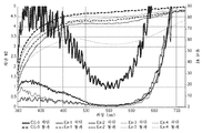
표준 텐터링(tentering), 포물선형 텐터링 및 다층에 대하여 가교결합제를 함유하는 경우와 이를 함유하지 않는 경우의 편광기 성능을 비교하는 투과 스펙트럼이 각각 도 7, 도 8 및 도 9에 비교되어 있다. 표준 텐터링 공정 (비교예 1 내지 비교예 4 vs. 비교예 6)에 대한 투과 스펙트럼이 도 7에 나타나 있다. 이 도면으로부터, 합성 스펙트럼에 대하여 가교결합제의 첨가에 의한 차이는 거의 인식되지 않는다. 포물선형 텐터링 공정 (실시예 1 내지 실시예 4 vs. 비교예 5)에 대하여 가교결합제를 함유하는 경우와 이를 함유하지 않는 경우의 편광기 성능을 비교하는 투과 스펙트럼이 도 8에 나타나 있다. 포물선형 텐터링 공정으로 제조된 이들 샘플의 경우, 제형에 대한 가교결합제의 첨가에 의한 명확한 대비가 있었다. 다층 필름의 경우 (실시예 5 vs. 비교예 7)에 대하여 가교결합제를 함유하는 경우와 이를 함유하지 않는 경우의 편광기 성능을 비교하는 투과 스펙트럼이 도 9에 나타나 있다.The transmission spectra comparing the polarizer performance with the standard tentering, the parabolic tentering and the multilayer with and without a cross-linking agent are compared in Figures 7, 8 and 9, respectively. The transmission spectrum for the standard tentering process (Comparative Examples 1 to 4 vs. Comparative Example 6) is shown in Fig. From this figure, the difference due to the addition of the crosslinking agent to the synthetic spectrum is hardly recognized. A transmission spectrum comparing the polarizer performance with and without a crosslinking agent for the parabolic tentering process (Examples 1 to 4 vs. Comparative Example 5) is shown in FIG. For these samples made by the parabolic tentering process, there was a clear contrast by the addition of cross-linking agent to the formulation. The transmission spectrum comparing the polarizer performance with and without a crosslinking agent for the multilayer film (Example 5 vs. Comparative Example 7) is shown in FIG.
실시예에 대한 광학 성능 특성이 표 5에 요약되어 있다. 비교예 1 내지 비교예 4로부터의 결과를 비교예 6으로부터의 결과와 비교하면, 표준 연신 공정/전통적인 연신 공정을 사용할 때 가교결합제의 첨가에 의한 차이를 거의 나타내지 않는다. 대조적으로, 실시예 1 내지 실시예 4로부터의 결과를 비교예 5로부터의 결과와 비교하면, 가교결합제의 첨가에 대하여 차단 상태 투과율 (최소 Tb%) 및 편광 효율 (최대 PE%)에 상당한 영향을 나타낸다.The optical performance characteristics for the examples are summarized in Table 5. Comparing the results from Comparative Example 1 to Comparative Example 4 with the results from Comparative Example 6 shows little difference due to the addition of cross-linking agent when using the standard stretching process / conventional stretching process. In contrast, comparing the results from Examples 1 to 4 with the results from Comparative Example 5 shows a significant effect on the blocking state transmittance (minimum Tb%) and polarization efficiency (maximum PE%) for the addition of the crosslinking agent .
[표 5][Table 5]

도면 내의 요소에 대한 설명은, 달리 지시되지 않는 한, 다른 도면 내의 대응하는 요소에 동등하게 적용되는 것으로 이해되어야 한다. 구체적인 실시 형태가 본 명세서에 예시 및 기술되어 있지만, 당업자는 본 발명의 범주로부터 벗어나지 않고서 다양한 대안 및/또는 등가의 구현예가 도시 및 기술된 구체적인 실시 형태를 대신할 수 있다는 것을 이해할 것이다. 본 출원은 본 명세서에 논의된 구체적인 실시 형태의 임의의 개조 또는 변형을 포함하도록 의도된다. 따라서, 본 발명은 오직 청구범위 및 이의 등가물에 의해서만 제한되는 것으로 의도된다.It should be understood that the description of the elements in the figures applies equally to the corresponding elements in the different drawings unless otherwise indicated. Although specific embodiments are illustrated and described herein, those skilled in the art will appreciate that various alternatives and / or equivalent implementations may be substituted for the specific embodiments shown and described without departing from the scope of the invention. This application is intended to cover any adaptations or variations of the specific embodiments discussed herein. It is therefore intended that the present invention be limited only by the claims and the equivalents thereof.
Claims (22)
배향된 중합체 제1 층을 포함하며, 배향된 중합체 제1 층은 폴리비닐 알코올 및 가교결합제를 포함하는 혼합물로부터 제조가능하며, 가교결합제는 폴리비닐 알코올과 가교결합제의 총 중량을 기준으로 5 내지 40 중량%로 혼합물에 포함되고, 배향된 중합체 제1 층은, U=(1/MDDR-1)/(TDDR1/2 -1)에 대하여, U는 적어도 0.85라는 점에서 실질적으로 단축 연신된 층이며, 여기서 MDDR은 기계 방향 연신비이고, TDDR은 횡방향 연신비인, 편광기.As the polarizer,
Wherein the oriented polymeric first layer comprises an oriented polymeric layer and wherein the oriented polymeric first layer can be prepared from a blend comprising polyvinyl alcohol and a crosslinking agent, wherein the crosslinking agent is present in an amount of from 5 to 40%, based on the total weight of the polyvinyl alcohol and crosslinking agent And the oriented polymeric first layer comprises a substantially uniaxially stretched layer in that U is at least 0.85 for U = (1 / MDDR-1) / (TDDR 1/2 -1) , Where MDDR is the machine direction stretch ratio and TDDR is the transverse stretch ratio.
용매 중에 폴리비닐 알코올 및 가교결합제의 혼합물을 형성하는 단계 - 혼합물에 포함된 가교결합제의 중량을 가교결합제의 중량과 폴리비닐 알코올의 중량의 합으로 나눈 값은 0.05 내지 0.3의 범위임 -;
혼합물을 제2 층 상에 코팅하는 단계;
혼합물을 건조시켜 용매를 제거함으로써, 건조된 코팅을 형성하는 단계;
코팅된 제2 층을 연신하여 건조된 코팅을 배향시킴으로써, 배향된 중합체 제1 층을 형성하는 단계를 포함하며,
코팅된 제2 층을 연신하는 단계는, 코팅된 제2 층을 기계 방향을 따라 연신기 내에서 이송하면서, 코팅된 제2 층의 대향하는 에지 부분을 유지하고, 발산 비선형 경로를 따라 대향하는 에지 부분을 이동시킴으로써 연신기 내에서 코팅된 제2 층을 연신하는 단계를 포함하는, 방법.A method of making a polarizer comprising an oriented polymer first layer,
Forming a mixture of a polyvinyl alcohol and a crosslinking agent in a solvent, wherein the weight of the crosslinking agent contained in the mixture divided by the sum of the weight of the crosslinking agent and the weight of the polyvinyl alcohol is in the range of 0.05 to 0.3;
Coating the mixture on the second layer;
Drying the mixture to remove the solvent to form a dried coating;
Stretching the coated second layer to orient the dried coating to form an oriented polymeric first layer,
The step of stretching the coated second layer is carried out by maintaining the opposing edge portions of the coated second layer while transferring the coated second layer in the machine direction along the machine direction, And stretching the coated second layer within the stretching machine by moving the portion of the second layer.
Applications Claiming Priority (3)
| Application Number | Priority Date | Filing Date | Title |
|---|---|---|---|
| US201662375479P | 2016-08-16 | 2016-08-16 | |
| US62/375,479 | 2016-08-16 | ||
| PCT/US2017/045305 WO2018034854A1 (en) | 2016-08-16 | 2017-08-03 | Polarizer |
Publications (1)
| Publication Number | Publication Date |
|---|---|
| KR20190032605A true KR20190032605A (en) | 2019-03-27 |
Family
ID=61197103
Family Applications (1)
| Application Number | Title | Priority Date | Filing Date |
|---|---|---|---|
| KR1020197007171A KR20190032605A (en) | 2016-08-16 | 2017-08-03 | Polarizer |
Country Status (6)
| Country | Link |
|---|---|
| US (1) | US11231536B2 (en) |
| JP (1) | JP7117288B2 (en) |
| KR (1) | KR20190032605A (en) |
| CN (1) | CN109642974B (en) |
| TW (1) | TW201821275A (en) |
| WO (1) | WO2018034854A1 (en) |
Cited By (1)
| Publication number | Priority date | Publication date | Assignee | Title |
|---|---|---|---|---|
| WO2022010179A1 (en) * | 2020-07-10 | 2022-01-13 | 삼성에스디아이 주식회사 | Optical film, polarizing plate comprising same, and optical display device comprising same |
Family Cites Families (43)
| Publication number | Priority date | Publication date | Assignee | Title |
|---|---|---|---|---|
| US4166871A (en) | 1977-06-29 | 1979-09-04 | Polaroid Corporation | Iodine stained light polarizer |
| US4659523A (en) | 1984-11-30 | 1987-04-21 | American Hoechst Corporation | Production of iodine stainable polyester polarizer film |
| US4895769A (en) | 1988-08-09 | 1990-01-23 | Polaroid Corporation | Method for preparing light polarizer |
| US5066108A (en) | 1989-12-22 | 1991-11-19 | Hughes Aircraft Company | High throughput contrast enhancement for polarized displays |
| US5882774A (en) | 1993-12-21 | 1999-03-16 | Minnesota Mining And Manufacturing Company | Optical film |
| US6096375A (en) | 1993-12-21 | 2000-08-01 | 3M Innovative Properties Company | Optical polarizer |
| US6111697A (en) | 1998-01-13 | 2000-08-29 | 3M Innovative Properties Company | Optical device with a dichroic polarizer and a multilayer optical film |
| US6549335B1 (en) | 2000-07-28 | 2003-04-15 | 3M Innovative Properties Company | High durability circular polarizer for use with emissive displays |
| WO2002016976A2 (en) | 2000-08-21 | 2002-02-28 | 3M Innovative Properties Company | Loss enhanced reflective optical filters |
| US6939499B2 (en) | 2001-05-31 | 2005-09-06 | 3M Innovative Properties Company | Processes and apparatus for making transversely drawn films with substantially uniaxial character |
| US6814899B2 (en) | 2002-02-12 | 2004-11-09 | 3M Innovative Properties Company | Enhanced K-type polarizer |
| JP4170015B2 (en) * | 2002-04-18 | 2008-10-22 | 株式会社クラレ | Polarizer |
| US6936960B2 (en) | 2003-01-10 | 2005-08-30 | Eastman Kodak Company | OLED displays having improved contrast |
| KR100916955B1 (en) | 2003-04-21 | 2009-09-14 | 닛토덴코 가부시키가이샤 | Polarizer, method for producing same, polarizing plate, optical film and image display |
| JP4888931B2 (en) | 2003-08-08 | 2012-02-29 | 日東電工株式会社 | Method for manufacturing superimposed film for liquid crystal display device, superimposed film for liquid crystal display device, and liquid crystal display device |
| TWI276850B (en) | 2004-09-15 | 2007-03-21 | Far Eastern Textile Ltd | Optical compensator for a liquid crystal display |
| CN100549738C (en) | 2005-03-10 | 2009-10-14 | 日本化药株式会社 | The Polarizer of iodine polarizing film and manufacture method thereof and this iodine polarizing film of use |
| US20080192345A1 (en) | 2005-03-10 | 2008-08-14 | Noriaki Mochizuki | Iodine Polarizing Film, a Method for Producing the Same, and a Polarizing Plate Using the Same |
| US20060227421A1 (en) | 2005-04-06 | 2006-10-12 | Stover Carl A | Optical bodies including strippable boundary layers |
| EP1872160A4 (en) * | 2005-04-22 | 2010-11-24 | Fujifilm Corp | Optical film, polarizing plate and liquid crystal display |
| JP4968669B2 (en) | 2005-07-28 | 2012-07-04 | 日本合成化学工業株式会社 | Polyvinyl alcohol film for polarizing film and polarizing film and polarizing plate using the same |
| US20070047080A1 (en) | 2005-08-31 | 2007-03-01 | 3M Innovative Properties Company | Methods of producing multilayer reflective polarizer |
| US7515231B2 (en) * | 2005-09-30 | 2009-04-07 | Teledyne Scientific & Imaging, Llc | Low temperature nematic liquid crystal alignment material and LCD compensator incorporating the liquid crystal alignment material |
| US20070228586A1 (en) | 2006-03-31 | 2007-10-04 | Merrill William W | Process for making an optical film |
| US7826009B2 (en) | 2006-12-21 | 2010-11-02 | 3M Innovative Properties Company | Hybrid polarizer |
| KR101393754B1 (en) | 2006-12-28 | 2014-05-12 | 닛토덴코 가부시키가이샤 | Process for producing polarizer, polarizer, polarizing plate, optical film, process for producing composite polarizing plate, composite polarizing plate, and image display device |
| JP5231181B2 (en) * | 2007-11-30 | 2013-07-10 | 日東電工株式会社 | Polarizing plate, manufacturing method thereof, optical film, and image display device |
| CN101981476B (en) | 2008-03-31 | 2014-03-19 | 3M创新有限公司 | Primer layer for multilayer optical film |
| JP4928529B2 (en) * | 2008-11-12 | 2012-05-09 | 日東電工株式会社 | Manufacturing method of polarizing plate, polarizing plate, optical film, and image display device |
| CN102317821A (en) | 2009-02-13 | 2012-01-11 | 日东电工株式会社 | Laminate optical body, optical film, liquid crystal display device using said optical film, and method for manufacturing laminate optical body |
| JP5819930B2 (en) | 2010-03-26 | 2015-11-24 | スリーエム イノベイティブ プロパティズ カンパニー | Non-flattened film and manufacturing process thereof |
| JP5478553B2 (en) | 2010-09-03 | 2014-04-23 | 日東電工株式会社 | Continuous web-like optical film laminate roll and method for producing the same |
| JP5502023B2 (en) | 2010-09-03 | 2014-05-28 | 日東電工株式会社 | Method for producing optical film laminate roll having polarizing film |
| JP4691205B1 (en) | 2010-09-03 | 2011-06-01 | 日東電工株式会社 | Method for producing optical film laminate including thin high-performance polarizing film |
| JP2012123229A (en) * | 2010-12-09 | 2012-06-28 | Sumitomo Chemical Co Ltd | Manufacturing method of polarizing laminate film and polarizing plate |
| KR101518495B1 (en) | 2011-11-07 | 2015-05-11 | 제일모직주식회사 | Light-polarizing film having enhanced photodurability and the fabrication method thereof |
| JP5985813B2 (en) | 2011-11-14 | 2016-09-06 | 日東電工株式会社 | Manufacturing method of polarizer, polarizer, polarizing plate, optical film, and image display device |
| SG11201506508SA (en) * | 2013-02-20 | 2015-09-29 | 3M Innovative Properties Co | Absorbing, reflecting and collimating polarizer stack and backlights incorporating same |
| JP2014205826A (en) | 2013-03-18 | 2014-10-30 | 日本合成化学工業株式会社 | Crosslinking agent, crosslinked polymer, and their applications |
| KR20150039982A (en) | 2013-10-04 | 2015-04-14 | 동우 화인켐 주식회사 | Method for preparing polarizer and polarizer |
| JP6077619B2 (en) | 2014-09-30 | 2017-02-08 | 日東電工株式会社 | Single protective polarizing film, polarizing film with pressure-sensitive adhesive layer, image display device, and continuous production method thereof |
| KR20160080335A (en) * | 2014-12-29 | 2016-07-08 | 동우 화인켐 주식회사 | Process for Preparing Polarizer |
| US10466398B2 (en) | 2015-06-15 | 2019-11-05 | 3M Innovative Properties Company | Optical stack including reflecting-absorbing polarizer |
-
2017
- 2017-08-03 US US16/318,836 patent/US11231536B2/en active Active
- 2017-08-03 KR KR1020197007171A patent/KR20190032605A/en unknown
- 2017-08-03 CN CN201780050318.2A patent/CN109642974B/en active Active
- 2017-08-03 JP JP2019508225A patent/JP7117288B2/en active Active
- 2017-08-03 WO PCT/US2017/045305 patent/WO2018034854A1/en active Application Filing
- 2017-08-15 TW TW106127533A patent/TW201821275A/en unknown
Cited By (1)
| Publication number | Priority date | Publication date | Assignee | Title |
|---|---|---|---|---|
| WO2022010179A1 (en) * | 2020-07-10 | 2022-01-13 | 삼성에스디아이 주식회사 | Optical film, polarizing plate comprising same, and optical display device comprising same |
Also Published As
| Publication number | Publication date |
|---|---|
| US11231536B2 (en) | 2022-01-25 |
| TW201821275A (en) | 2018-06-16 |
| US20190285787A1 (en) | 2019-09-19 |
| JP7117288B2 (en) | 2022-08-12 |
| JP2019532325A (en) | 2019-11-07 |
| CN109642974A (en) | 2019-04-16 |
| CN109642974B (en) | 2022-04-15 |
| WO2018034854A1 (en) | 2018-02-22 |
Similar Documents
| Publication | Publication Date | Title |
|---|---|---|
| KR100582972B1 (en) | An Optical Polarizer and a Method of Making the Same | |
| US6335051B1 (en) | Dichroic polarizing film and optical polarizer containing the film | |
| CN100380145C (en) | Light polarizing film | |
| US11378844B2 (en) | Viewer-side polarizing plate for liquid crystal display device, and liquid crystal display device comprising same | |
| KR102052843B1 (en) | Polarizer-protecting polyester film and manufacturing method thereof and polarization plate using the same | |
| JP6366277B2 (en) | Light control device, light control window, and optical laminate for light control device | |
| TWI739941B (en) | Broadband wavelength film and manufacturing method thereof, and manufacturing method of circularly polarized film | |
| JP2020064278A (en) | Polarizing plate with phase difference layer and image display device using the same | |
| TW201923417A (en) | Head-up display apparatus | |
| KR20060005409A (en) | Process for producing coated sheet, optically functional layer, optically compensating plate, optical device and image display | |
| TW202033339A (en) | Alignment film for transferring liquid crystal compound alignment layer | |
| JP2020064277A (en) | Polarizing plate with phase difference layer and image display device using the same | |
| KR20190032605A (en) | Polarizer | |
| JP6797499B2 (en) | Polarizing plate with retardation layer and image display device using it | |
| JP7387591B2 (en) | A roll of film containing a multilayer birefringent reflective polarizer and a polyvinyl alcohol layer, with small variations in the pass axis. | |
| TWI675871B (en) | Polarizing plate and optical display device comprising the same | |
| JP2020064279A (en) | Polarizing plate with phase difference layer and image display device using the same | |
| JP2020064280A (en) | Polarizing plate with phase difference layer and image display device using the same | |
| JP6804168B2 (en) | Polarizing plate with retardation layer and image display device using it | |
| TWI658078B (en) | Polyester protective film for polarizing plate, polarizing plate comprising the same, and liquid crystal display comprising the same | |
| TWI541529B (en) | Optical element and viewing angle improving method for polarizing film using said optical element | |
| TW201923418A (en) | Head-up display device | |
| JP2008203753A (en) | Polarizing film and its producing method | |
| TW201923429A (en) | Head-up display device | |
| WO2023176632A1 (en) | Optical laminate, lens, and display method |