CN109642974B - Polarizer - Google Patents
Polarizer Download PDFInfo
- Publication number
- CN109642974B CN109642974B CN201780050318.2A CN201780050318A CN109642974B CN 109642974 B CN109642974 B CN 109642974B CN 201780050318 A CN201780050318 A CN 201780050318A CN 109642974 B CN109642974 B CN 109642974B
- Authority
- CN
- China
- Prior art keywords
- layer
- polarizer
- oriented
- mixture
- crosslinking agent
- Prior art date
- Legal status (The legal status is an assumption and is not a legal conclusion. Google has not performed a legal analysis and makes no representation as to the accuracy of the status listed.)
- Active
Links
Images


Classifications
-
- G—PHYSICS
- G02—OPTICS
- G02B—OPTICAL ELEMENTS, SYSTEMS OR APPARATUS
- G02B5/00—Optical elements other than lenses
- G02B5/30—Polarising elements
- G02B5/3025—Polarisers, i.e. arrangements capable of producing a definite output polarisation state from an unpolarised input state
- G02B5/3033—Polarisers, i.e. arrangements capable of producing a definite output polarisation state from an unpolarised input state in the form of a thin sheet or foil, e.g. Polaroid
- G02B5/3041—Polarisers, i.e. arrangements capable of producing a definite output polarisation state from an unpolarised input state in the form of a thin sheet or foil, e.g. Polaroid comprising multiple thin layers, e.g. multilayer stacks
- G02B5/305—Polarisers, i.e. arrangements capable of producing a definite output polarisation state from an unpolarised input state in the form of a thin sheet or foil, e.g. Polaroid comprising multiple thin layers, e.g. multilayer stacks including organic materials, e.g. polymeric layers
-
- B—PERFORMING OPERATIONS; TRANSPORTING
- B29—WORKING OF PLASTICS; WORKING OF SUBSTANCES IN A PLASTIC STATE IN GENERAL
- B29D—PRODUCING PARTICULAR ARTICLES FROM PLASTICS OR FROM SUBSTANCES IN A PLASTIC STATE
- B29D11/00—Producing optical elements, e.g. lenses or prisms
- B29D11/00634—Production of filters
- B29D11/00644—Production of filters polarizing
-
- B—PERFORMING OPERATIONS; TRANSPORTING
- B32—LAYERED PRODUCTS
- B32B—LAYERED PRODUCTS, i.e. PRODUCTS BUILT-UP OF STRATA OF FLAT OR NON-FLAT, e.g. CELLULAR OR HONEYCOMB, FORM
- B32B27/00—Layered products comprising a layer of synthetic resin
- B32B27/06—Layered products comprising a layer of synthetic resin as the main or only constituent of a layer, which is next to another layer of the same or of a different material
- B32B27/08—Layered products comprising a layer of synthetic resin as the main or only constituent of a layer, which is next to another layer of the same or of a different material of synthetic resin
-
- B—PERFORMING OPERATIONS; TRANSPORTING
- B29—WORKING OF PLASTICS; WORKING OF SUBSTANCES IN A PLASTIC STATE IN GENERAL
- B29K—INDEXING SCHEME ASSOCIATED WITH SUBCLASSES B29B, B29C OR B29D, RELATING TO MOULDING MATERIALS OR TO MATERIALS FOR MOULDS, REINFORCEMENTS, FILLERS OR PREFORMED PARTS, e.g. INSERTS
- B29K2029/00—Use of polyvinylalcohols, polyvinylethers, polyvinylaldehydes, polyvinylketones or polyvinylketals or derivatives thereof as moulding material
- B29K2029/04—PVOH, i.e. polyvinyl alcohol
-
- B—PERFORMING OPERATIONS; TRANSPORTING
- B29—WORKING OF PLASTICS; WORKING OF SUBSTANCES IN A PLASTIC STATE IN GENERAL
- B29K—INDEXING SCHEME ASSOCIATED WITH SUBCLASSES B29B, B29C OR B29D, RELATING TO MOULDING MATERIALS OR TO MATERIALS FOR MOULDS, REINFORCEMENTS, FILLERS OR PREFORMED PARTS, e.g. INSERTS
- B29K2995/00—Properties of moulding materials, reinforcements, fillers, preformed parts or moulds
- B29K2995/0018—Properties of moulding materials, reinforcements, fillers, preformed parts or moulds having particular optical properties, e.g. fluorescent or phosphorescent
Abstract
A polarizer is described that includes an oriented first polymer layer. The oriented first polymer layer can be prepared from a mixture of polyvinyl alcohol and a crosslinking agent, wherein the crosslinking agent is included in the mixture at a content of 5 to 40 wt%, based on the total weight of the polyvinyl alcohol and the crosslinking agent. The oriented first polymer layer is a substantially uniaxially stretched layer, where U ═ 1/MDDR-1)/(TDDR1/2-1), U is at least 0.85, MDDR is machine direction stretch ratio, and TDDR is cross direction stretch ratio.
Description
Background
The absorbing polarizer may be prepared by stretching a polyvinyl alcohol layer so that the polyvinyl alcohol molecules in the layer are aligned and dyeing the aligned layer with iodine. Such polarizers have been used in a variety of display applications.
Disclosure of Invention
In some aspects of the present description, a polarizer including an oriented first polymer layer is provided. The oriented first polymer layer may be prepared from a mixture comprising polyvinyl alcohol and a crosslinking agent, wherein the crosslinking agent is included in the mixture at a content of 5 to 40 wt%, based on the total weight of the polyvinyl alcohol and the crosslinking agent. The oriented first polymer layer is a substantially uniaxially stretched layer, where U ═ 1/MDDR-1)/(TDDR1/2-1), U is at least 0.85, MDDR is machine direction stretch ratio and TDDR is cross direction stretch ratio.
In some aspects of the present description, a method of manufacturing a polarizer having an oriented first polymer layer is provided. The method comprises forming a mixture of polyvinyl alcohol and a crosslinking agent in a solvent; applying the mixture to a second layer; drying the mixture to remove the solvent, thereby forming a dried coating; stretching the coated second layer to orient the dried coating, thereby forming an oriented first polymer layer. The quotient of the weight of the crosslinking agent contained in the mixture divided by the sum of the weight of the crosslinking agent and the weight of the polyvinyl alcohol is in the range of 0.05 to 0.3. Stretching the coated second layer includes conveying the coated second layer in a machine direction within the stenter while maintaining opposing edge portions of the coated second layer, and stretching the coated second layer within the stenter by moving the opposing edge portions along diverging non-linear paths.
Drawings
FIG. 1 is a cross-sectional view of a polarizer;
fig. 2 is a diagram of a method for forming an oriented polymer layer.
Fig. 3 is a schematic top plan view of the stenter;
fig. 4 to 5 are schematic cross-sectional views of the display;
FIG. 6 is a cross-sectional view of a multilayer optical film; and
fig. 7 to 9 are transmission spectra of various polarizers.
Detailed Description
In the following description, reference is made to the accompanying drawings, which form a part hereof and in which is shown by way of illustration various embodiments. The figures are not necessarily to scale. It is to be understood that other embodiments are contemplated and may be made without departing from the scope or spirit of the present disclosure. The following detailed description is, therefore, not to be taken in a limiting sense.
The absorbing polarizer is typically made by stretching a layer of polyvinyl alcohol (PVA or PVOH) such that the PVA molecules are aligned in the layer and the aligned layer is dyed with iodine. The iodine molecules align with the oriented PVA molecules. Incident light polarized in the aligned direction (i.e., polarized along the block axis of the polarizer) is absorbed or partially absorbed by iodine and incident light polarized in the orthogonal direction (i.e., polarized along the pass axis of the polarizer) is transmitted or partially transmitted through the polarizer.
Another type of polarizer is a polymeric multilayer optical film that includes alternating polymer layers configured to provide reflection to light polarized along a block axis and to transmit light polarized along a pass axis orthogonal to the block axis. For example, such films may be prepared by extruding a stack of alternating polymer layers of a first type and a second type and uniaxially or near uniaxially stretching the extruded stack to orient at least one of the polymer layers of the first type and the second type, as generally described in U.S. Pat. No. 5,882,774(Jonza et al). Parabolic stenters or tenters (e.g., such as those described in U.S. patent 6,916,440 (Jackson)) have been used to improve the degree of uniaxial orientation of birefringent layers in reflective polarizers.
In some cases, it may be desirable to include both an absorbing polarizer and a reflective polarizer in display applications. For example, a reflective polarizer may be used for polarization recycling in liquid crystal display applications, and an absorbing polarizer may be added to the reflective polarizer to improve the extinction efficiency. Combining an absorbing polarizer with a reflective polarizer has been described in U.S. patents 6,096,375(Ouderkirk et al), 6,697,195 (weber et al), 7,826,009 (weber et al), and 6,111,697(Kausch et al), each of which is hereby incorporated by reference herein to the extent not inconsistent with this specification.
In accordance with the present specification, it has been found that polarizers comprising modified PVA layers prepared by including a suitable cross-linking agent in the PVA impart improved optical properties if the modified PVA layers are oriented to a higher degree of uniaxial orientation than can be achieved using conventional linear tenters. In particular, it has been found that including a suitable cross-linking agent in the PVA layer and stretching the layer by moving the opposing edge portions along divergent non-linear paths (e.g., using a parabolic tenter to substantially uniaxially orient the layer) in combination to form an absorbing polarizer achieves both a low minimum transmission (e.g., less than 0.1%) for normally incident light in the wavelength range of interest and polarized along the block axis and a high maximum transmission (e.g., greater than 75%) for normally incident light in the wavelength range of interest and polarized along the pass axis. For example, the wavelength range of interest may be the visible range (400nm to 700nm), or may be 540nm to 640 nm. In some embodiments, the absorbing polarizer has a Polarization Efficiency (PE) of at least 99.8% or at least 99.9%. The polarization efficiency is given by equation 1: :

wherein MaxLight transmissionIs the maximum transmission state at normal incidence in the wavelength range of interest, and MinLight blockingIs the minimum block state for normal incidence in the wavelength range of interest.
FIG. 1 is a schematic cross-sectional view of a polarizer 100 that includes an oriented first polymer layer 110 disposed on a substrate 120. The substrate 120 includes a second layer 122, which second layer 122 can be, for example, a single polymeric layer, or this can be a polymeric multilayer optical film, which can be, for example, a polymeric multilayer reflective polarizer. In the illustrated embodiment, the substrate 120 further includes an additional layer 124, which additional layer 124 can be, for example, a retarder (e.g., a quarter-wave retarder). In alternative embodiments, this additional layer 124 is omitted, and in some cases, the second layer 122 is a retarder. A primer 126 (which primer 126 may optionally be omitted) is disposed between the oriented first polymer layer 110 and the second layer 122. The primer 126 can be considered a layer of the substrate 120, or can be considered a layer between the oriented first polymeric layer 110 and the substrate. The third layer 130 is disposed adjacent the oriented first polymer layer 110 opposite the second layer 122. In some embodiments, the third layer 130 is or includes a protective layer, an adhesive layer, a retarder, or a combination thereof. In some embodiments, the third layer 130 is omitted.
In some embodiments, one or both of the second layer 122 and the third layer 130 are an optically transparent polymer layer or a plurality of optically transparent polymer layers. For example, suitable polymer layers include those prepared from polyethylene terephthalate (PET), glycol-modified PET (petg), polyethylene naphthalate (PEN), other polyesters or copolyesters, polycarbonates, and copolymers thereof.
In embodiments including a retarder as a layer in the polarizer, the retarder may be a quarter-wave retarder having an in-plane retardation of 1/4 that is approximately equal to the wavelength of interest. The wavelength of interest may be any wavelength in the visible range (400nm to 700nm), and may be, for example, 550 nm. Unless otherwise indicated, the quarter-wave retarder refers to a retarder having an in-plane retardation of one quarter of the wavelength of visible light. In some embodiments, a quarter-wave retarder having an in-plane retardation between 100nm and 175nm or between 125nm and 150nm is used in the polarizer. In some embodiments, retarders are used that have in-plane retardation other than one quarter of the wavelength of visible light. For example, a half-wavelength retarder or other retarder may be used. In some embodiments, retarders with in-plane retardation between 100nm and 350nm or between 200nm and 350nm are used in the polarizer. The in-plane retardation of a layer refers to the absolute value of the difference between the indices of refraction in two orthogonal planes at the wavelength of interest multiplied by the thickness of the layer.
The aligned first polymer layer 110 includes a dichroic material, such as iodine or other dyes or pigments, that provides absorption over a range of wavelengths. The wavelength range depends on the type of dye and/or pigment used. In display applications, it is generally desirable that the wavelength range include the visible range (400nm to 700nm) or at least a substantial portion of the visible range (e.g., 450nm to 650 nm). For example, the iodine molecules align with the polyvinyl alcohol molecules in the oriented first polymer layer 110 and thus provide strong absorption for light polarized along the orientation direction while allowing transmission of light of orthogonal polarization. For example, the x-axis (referring to the x-y-z coordinate system of FIG. 1) may be the block axis for the oriented first polymer layer 110, and in embodiments where the second layer 122 is a reflective polarizer, may also be the block axis of the second layer 122. Likewise, the y-axis can be the transmission axis for the oriented first polymer layer 110, and in embodiments where the second layer 122 is a reflective polarizer, can also be the transmission axis of the second layer 122.
The oriented first polymer layer 110 may be prepared from a mixture comprising polyvinyl alcohol and a crosslinking agent. In some embodiments, the crosslinking agent is included in the mixture at a level of 5 to 40 wt%, or 5 to 30 wt%, based on the total weight of the polyvinyl alcohol and the crosslinking agent. In some embodiments, a mixture of polyvinyl alcohol and a crosslinking agent is formed in a solvent and the mixture is coated onto the second layer. In some embodiments, the mixture of polyvinyl alcohols is diluted in a solvent to 10 to 20 weight percent of the solids. In some embodiments, the quotient of the weight of the crosslinking agent contained in the mixture divided by the sum of the weight of the crosslinking agent and the weight of the polyvinyl alcohol is in the range of 0.05 to 0.3. In some embodiments, the crosslinking agent includes one or more formaldehyde adducts, such as melamine formaldehyde and urea formaldehyde.
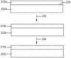
Fig. 2 illustrates a method for forming an oriented first polymer layer 210 c. The oriented first polymer layer 210c may be prepared by coating the mixture 210a on the second layer 220 a. Drying (step 242) the mixture to remove the solvent, thereby forming a dried coating 210b on the second layer 222b (which second layer 222b may be the same as second layer 222a, or may be altered by a drying process (e.g., thermally relaxed)); the coated second layer 222b is substantially uniaxially stretched (step 244) to orient the dried coating 210b, thereby forming an oriented first polymer layer 210c on the second layer 222c (which second layer 222c may be the same as the second layer 222b except for the thickness of the layer, which will typically be reduced by the stretching process, or may be altered (e.g., oriented) by the stretching process).
In some embodiments, the mixture is coated with a primer in a single step using, for example, a slip-coater. In other embodiments, a primer is applied to the major surface 225 of the second layer 220a, and then the mixture is applied to the primed surface of the second layer 220 a. In other embodiments, no primer is used. In some embodiments, the major surface 225 of the second layer 220a, and in some embodiments, the major surface 225 of the second layer 220a, is surface treated prior to application of the primer, and the mixture is applied directly to the surface treated surface. Suitable surface treatments include, for example, plasma treatment or corona treatment.
For example, the drying step 242 may be performed at a temperature in the range of 25 ℃ to 180 ℃ or 50 ℃ to 150 ℃ or 70 ℃ to 120 ℃ or 25 ℃ to 180 ℃. In some embodiments, the mixture is at a temperature above 150 ℃ for no more than 5 minutes prior to stretching. In some embodiments, the thickness of the dried layer of polyethanol is from 1.5 microns to 15 microns prior to stretching. In some embodiments, the primer layer has a thickness of from 0.45 microns to 3 microns prior to stretching. The stretching step 244 may be performed at a temperature in the range of 25 ℃ to 180 ℃, or 50 ℃ to 180 ℃, or 110 ℃ to 180 ℃. In some embodiments, the thickness of the layer of polyglycolic acid after the stretching step is from 0.5 micrometers to 5 micrometers. In some embodiments, the primer layer has a thickness after the stretching step of from 0.15 microns to 1 micron.
The oriented first polymer layer 110 or the oriented first polymer layer 210c may be dyed with an absorbing dye such as iodine to provide an absorbing polarizer. Dyeing an oriented polyvinyl alcohol layer with iodine to make an absorbing polarizer is known in the art and is generally described, for example, in U.S. patent 4,166,871 (Shuler). As an alternative to dyeing the alignment layer, a dye or pigment capable of aligning with the polyvinyl alcohol chains may be added to the mixture prior to coating or stretching to form the alignment layer. In some embodiments, a dichroic dye is added to the mixture to provide absorption in a desired wavelength range.
Fig. 3 is a schematic view of a stenter 350 for transporting a coated second layer 300 in a longitudinal direction (y-direction, see x-y-z coordinate system in fig. 3) within the stenter, while holding opposing edge portions 300a and 300b of the coated second layer 300 and stretching the coated second layer 300 within the stenter 350 by moving the opposing edge portions 300a and 300b along diverging non-linear paths 352a and 352 b. In some embodiments, oriented first polymer layer 110 is a substantially uniaxially stretched layer, where U ═ 1/MDDR-1)/(TDDR1/2-1), U is at least 0.85, wherein MDDR is the machine direction (y direction) stretch ratio and TDDR is the cross direction (x direction) stretch ratio. In some embodiments, the non-linear path 352a and the non-linear path 352b are parabolic. Further details regarding stenters suitable for substantially uniaxially stretching films are described in U.S. patent 6,916,440(Jackson et al), which is hereby incorporated by reference to the extent not inconsistent with this specification. In some embodiments, the layer is stretched with an MDDR in the range of 3 to 8 or 4 to 7 at a temperature of 110 ℃ to 180 ℃ or 130 ℃ to 170 ℃.
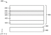
The polarizers of the present description are useful in a variety of display applications. Fig. 4 is a schematic cross-sectional view of a display 490 including a first polarizer 400 and a display panel 480. Display 490 may include additional polarizers as further described elsewhere herein. The display 490 is configured to provide light to a viewer positioned generally in the z-direction of the display 490, see the x-y-z coordinate system of FIG. 4. The display panel 480 has a light output side 482, and the first polarizer 400 is disposed adjacent to the light output side 482 and facing the light output side 482. In some embodiments, the display panel 480 is an Organic Light Emitting Diode (OLED) display panel, and in some embodiments, the display panel 480 is a Liquid Crystal Display (LCD) panel.
The first polarizer 400 (which first polarizer 400 may correspond to polarizer 100) includes an oriented first polymer layer 410, a second layer 422 (which may be, for example, a reflective polarizer), and further includes an additional layer 424, which additional layer 424 may be, for example, a retarder (e.g., a quarter-wave retarder). In alternative embodiments, the additional layer 424 is omitted, and in some cases, the second layer 422 is a retarder. An optional primer 426 is disposed between the oriented first polymer layer 410 and the second layer 422. Third layer 430 is disposed adjacent to oriented first polymer layer 410 opposite second layer 422. An optional primer 436 is disposed between the oriented first polymer layer 410 and the third layer 430. In some embodiments, the third layer 430 is or includes a protective layer, an adhesive layer, a retarder, or a combination thereof. In some embodiments, first layer 430 is omitted.
Fig. 5 is a schematic cross-sectional view of a display 590 comprising a first polarizer 500a, a second polarizer 500b, and a display panel 580. The display 590 is configured to provide light to a viewer generally located in the z-direction of the display 590, see the x-y-z coordinate system of FIG. 5. The display panel 580 has a light output side 582, and the first polarizer 500a is disposed adjacent to the light output side 582 and facing the light output side 582. The display panel 580 also has a light input side 584, and a second polarizer 500b is disposed adjacent to the light input side 584 and faces the light input side 584. The first polarizer 500a includes an oriented first polymer layer 510a, a second layer 522a, and a third layer 530 a. The second polarizer 500b includes an oriented first polymer layer 510b, a second layer 522b, and third and fourth layers 530b, 528 b. One or more of layer 522a, layer 530, layer 522b, layer 530b, and layer 528b may optionally be omitted. A primer layer may be disposed between any two immediately adjacent layers shown in fig. 5. In some embodiments, the third layer 530a and/or the third layer 530b is a protective layer, an adhesive layer, a retarder, or a combination thereof. In some embodiments, the second layer 522a is a reflective polarizer or retarder. In some embodiments, the second layer 522a is a quarter-wave retarder. In some embodiments, the second layer 522a includes both a reflective polarizer and a retarder. In some embodiments, second layer 522b is a reflective polarizer and fourth layer 528b is a retarder, which may be a quarter-wave retarder. In some implementations, the display panel 580 is a transmissive spatial light modulator, such as an LCD panel.
The oriented first polymeric layer may be disposed on a second layer, which may be a polymeric multilayer optical film. FIG. 6 is a cross-sectional view of a polymeric multilayer optical film 613, the polymeric multilayer optical film 613 including a plurality of first layers 657 alternating with a plurality of second layers 659. In some embodiments, the polymeric multilayer optical film 613 includes at least one dichroic layer 655, which dichroic layer 655 may be an outer layer as shown in fig. 6, or may be alternating layers 657 and 659. Polymeric multilayer optical films comprising one or more dichroic layers are further described in U.S. Pat. Nos. 6,096,375(Ouderkirk et al), 6,697,195 (Weber et al), 7,826,009 (Weber et al), and 6,111,697(Kausch et al).
The following is a list of exemplary embodiments of the present specification.
Embodiment 6 is the polarizer of embodiment 5, wherein the third layer comprises a protective layer, an adhesive layer, a retarder, or a combination thereof.
Embodiment 9 is the polarizer of embodiment 8, wherein the polymeric multilayer optical film comprises a reflective polarizer.
Embodiment 11 is the polarizer of embodiment 8, wherein the polymeric multilayer optical film comprises at least one dichroic layer.
Embodiment 12 is the polarizer of embodiment 8, wherein a retarder is disposed on the polymeric multilayer optical film opposite the oriented first polymeric layer.
Embodiment 13 is the polarizer of embodiment 12, wherein the retarder is a quarter-wave retarder.
Embodiment 14 is the polarizer of embodiment 8, wherein a retarder is disposed on the oriented first polymer layer opposite the polymeric multilayer optical film.
Embodiment 15 is the polarizer of embodiment 8, wherein a retarder is disposed between the oriented first polymer layer and the polymeric multilayer optical film.
Embodiment 16 is the polarizer of embodiment 4, further comprising a primer disposed between the oriented first polymer layer and the second layer.
Embodiment 17 is the polarizer of embodiment 1, wherein a retarder is disposed on the oriented first polymer layer.
Embodiment 18 is the polarizer of embodiment 17, wherein the retarder is a quarter-wave retarder.
Embodiment 19a is a display comprising the first polarizer of any one of embodiments 1-18.
Embodiment 19 is a display comprising the first polarizer of embodiment 1.
Embodiment 21 is the display of embodiment 20, wherein the first polarizer further comprises a retarder disposed between the oriented first polymer layer and the display panel.
Embodiment 22 is the display of embodiment 21, wherein the retarder is a quarter-wave retarder.
Embodiment 23 is the display of embodiment 21, wherein the display panel is an organic light emitting display panel.
Embodiment 24 is the display of embodiment 20, wherein the first polarizer comprises a second layer disposed between the oriented first polymer layer and the display panel.
Embodiment 25 is the display of embodiment 24, wherein the second layer comprises a polymeric multilayer optical film.
Embodiment 26 is the display of embodiment 25, wherein the polymeric multilayer optical film comprises a reflective polarizer.
Embodiment 27 is the display of embodiment 25, wherein the first polarizer further comprises a retarder.
Embodiment 28 is the display of embodiment 27, wherein the polymeric multilayer optical film is disposed between the oriented first polymer layer and the retarder.
Embodiment 29 is the display of embodiment 27, wherein the retarder is disposed between the polymeric multilayer optical film and the oriented first polymer layer.
Embodiment 31 is the display of embodiment 27, wherein the retarder is a quarter-wave retarder.
Embodiment 32 is the display of embodiment 20, wherein the first polarizer further comprises a third layer, the oriented first polymer layer disposed between the third layer and the display panel.
Embodiment 33 is the display of embodiment 20, further comprising a second polarizer of embodiment 1 disposed adjacent to and facing a light input side of the display panel.
Embodiment 34 is the display of embodiment 33, wherein the second polarizer comprises a second layer and a third layer, the third layer disposed between the second layer and the display panel, the oriented first polymer layer of the second polarizer disposed between the second layer and the third layer of the second polarizer.
Embodiment 35 is the display of embodiment 34, wherein the second layer of the second polarizer comprises a polymeric multilayer optical film.
Embodiment 36 is the display of embodiment 35, wherein the polymeric multilayer optical film comprises a reflective polarizer.
Embodiment 37 is the display of embodiment 34, wherein the third layer of the second polarizer comprises a protective layer, an adhesive layer, a retarder, or a combination thereof.
Embodiment 38 is the display of embodiment 33, wherein the second polarizer comprises a polymeric multilayer optical film, the oriented first polymer layer of the second polarizer disposed between the display panel and the polymeric multilayer optical film.
Embodiment 39 is the display of embodiment 38, wherein the second polarizer further comprises a retarder disposed on the polymeric multilayer optical film opposite the oriented first polymeric layer of the second polarizer.
Embodiment 41 is the display of embodiment 39, wherein the polymeric multilayer optical film comprises a reflective polarizer.
Embodiment 42 is the display of embodiment 33, wherein the first polarizer comprises a second layer disposed between the display panel and the oriented first polymer layer of the first polarizer.
Embodiment 43 is the display of embodiment 42, wherein the second layer of the first polarizer comprises at least one of a polymeric multilayer optical film and a retarder.
Embodiment 44 is the display of embodiment 33, wherein the display panel is a Liquid Crystal Display (LCD) panel.
Embodiment 45 is the display of embodiment 19, further comprising a display panel having a light input side, the first polarizer disposed adjacent to and facing the light input side.
Embodiment 46 is the polarizer of embodiment 1, wherein the crosslinking agent comprises one or more formaldehyde adducts.
Embodiment 47 is the polarizer of embodiment 1, wherein the crosslinking agent comprises melamine formaldehyde and is included in the mixture at a content of 5 wt% to 30 wt%.
Embodiment 48 is the polarizer of embodiment 1, wherein the crosslinking agent comprises urea formaldehyde and is included in the mixture at a content of 5 to 30 wt.%.
Embodiment 49 is the polarizer of embodiment 1, wherein the oriented first polymer layer has a minimum transmission of less than 0.1% for normally incident light in a wavelength range from 540nm to 640nm polarized along a block axis and a maximum transmission of at least 75% for normally incident light in a wavelength range from 540nm to 640nm polarized along a pass axis orthogonal to the block axis.
Embodiment 49b is a display comprising the first polarizer of any of embodiments 46-48.
forming a mixture of polyvinyl alcohol and a crosslinking agent in a solvent, a quotient of a weight of the crosslinking agent contained in the mixture divided by a sum of the weight of the crosslinking agent and the weight of the polyvinyl alcohol being in a range of 0.05 to 0.3;
applying the mixture to a second layer;
drying the mixture to remove the solvent, thereby forming a dried coating;
stretching the coated second layer to orient the dried coating layer to form the oriented first polymer layer,
wherein stretching the coated second layer comprises conveying the coated second layer in a machine direction within a stenter while maintaining opposing edge portions of the coated second layer, and stretching the coated second layer within the stenter by moving the opposing edge portions along diverging non-linear paths.
Embodiment 51 is the method of embodiment 50, wherein the nonlinear path is a parabolic path.
Embodiment 52 is the method of embodiment 50, wherein the stretching step comprises stretching the coated second layer in the machine direction at a stretch ratio of MDDR and stretching the coated second layer in the cross direction at a stretch ratio of TDDR, wherein U ═ 1/MDDR-1)/(TDDR1/2-1) is at least 0.85.
Embodiment 53 is the method of embodiment 50, wherein the mixture further comprises a dichroic dye.
Embodiment 54 is the method of embodiment 50, further comprising dyeing the dried coating.
Embodiment 55 is the method of embodiment 50, wherein the drying is performed at a temperature in the range of 25 ℃ to 180 ℃.
Embodiment 56 is the method of embodiment 50, wherein the drying is performed at a temperature in the range of 50 ℃ to 150 ℃.
Embodiment 57 is the method of embodiment 50, wherein the drying is performed at a temperature in the range of 70 ℃ to 120 ℃.
Embodiment 58 is the method of embodiment 50, wherein the stretching is performed at a temperature in a range of 25 ℃ to 180 ℃.
Embodiment 59 is the method of embodiment 50, wherein the stretching is performed at a temperature in the range of 50 ℃ to 180 ℃.
Embodiment 61 is the method of embodiment 50, wherein the mixture is at a temperature greater than 150 ℃ for no more than 5 minutes prior to stretching.
Embodiment 62 is the method of embodiment 50, wherein the crosslinking agent comprises one or more formaldehyde adducts.
Embodiment 63 is the method of embodiment 50, wherein the crosslinking agent comprises melamine formaldehyde.
Embodiment 64 is the method of embodiment 50, wherein the crosslinking agent comprises urea formaldehyde.
Embodiment 65 is the method of embodiment 50, wherein the second layer comprises a plurality of alternating polymer layers.
Embodiment 66 is the method of embodiment 65, wherein after the stretching step, the second layer comprises a reflective polarizer.
Embodiment 67 is the method of embodiment 50, wherein the applying step comprises applying a primer directly onto a major surface of the second layer and applying the mixture onto the primer.
Embodiment 68 is the method of embodiment 67, wherein the primer and the mixture are coated in a single step.
Embodiment 69 is the method of embodiment 67, further comprising surface treating the major surface of the second layer prior to applying the primer.
Embodiment 71 is the method of embodiment 50, wherein the oriented first polymer layer has a minimum transmission of less than 0.1% for normally incident light in the wavelength range of 540nm to 640nm polarized along a block axis and a maximum transmission of at least 75% for normally incident light in the wavelength range of 540nm to 640nm polarized along a pass axis orthogonal to the block axis.
Examples
All parts, percentages, ratios, etc. in these examples are by weight unless otherwise indicated. The materials used in the embodiments are listed in table 1. Unless otherwise indicated, solvents and other reagents used were obtained from Sigma-Aldrich Chemical Company of Milwaukee, Wis.
TABLE 1 materials


PVOH coating solution
A 10% solids solution of POVAL28-99 grade polyvinyl alcohol (PVOH or PVA) was prepared in water by first adding water to a temperature controlled kettle at room temperature. The PVOH resin was added with stirring. The mixture was heated to 90 to 105 ℃ and stirring was continued at this temperature for 3 hours. The solution was allowed to cool and drained from the kettle. To the cooled solution was added 0.1% of the solution of a surfactant. With mixing, the formaldehyde adduct-type crosslinker is added at a concentration of 5% to 40% based on PVOH resin solids. In some samples, isopropyl alcohol (IPA) is incorporated into the PVOH dissolution process at concentrations up to 15%. PVOH is summarized in tables 2 and 3.
TABLE 2 PVOH solutions
| Components | Percentage of solution |
| POVAL 28-99 | 10 |
| Water (W) | 74.9-89.9 |
| Surface active agent | 0.05-0.5 |
| IPA | 0-15 |
TABLE 3 PVOH solutions with crosslinker
| Components | Percentage of solution |
| POVAL 28-99 | 10 |
| Water (W) | 75-94.5 |
| Surface active agent | 0.05-0.5 |
| IPA | 0-15 |
| Crosslinking agent | 0.5-4 |
Primer coating solution
The primer solutions summarized in table 4 were prepared. The solution comprised a blend of sulfonated polyester solution, copolyester dispersion and cross-linking agent in a ratio of 72.5:10.8: 16.7. As shown in table 4, the resin in water blend was diluted and surfactant was added at 0.1% of the solution.
TABLE 4 primer solution
| Components | Percentage of solution |
| WB50 | 72.1 |
| EASTEK 1100 | 6.2 |
| TOMADOL 25-9 | 0.1 |
| CYMEL 327/328 | 3.7 |
| Water (W) | 17.9 |
Example 1: POVAL28-99+ 20% CYMEL 327
The absorbing polarizer was prepared as follows. A 3-layer cast film was first prepared in the conventional manner for polyester films by passing the material through a film die and extruding it onto a chill roll, where it was quenched. Both outer layers were formed from 90/10coPEN, the polymer was composed of 90 mole% polyethylene naphthalate (PEN) and 10 mole% polyethylene terephthalate (PET), and the central layer was formed from a blend of polycarbonate and copolyester (PC: coPET), where the molar ratio of PC: coPET was approximately 42.5 mole% PC and 57.5 mole% coPET, and the Tg was 105 degrees celsius. After cast film quenching, corona treatment was applied, then primer dope solution was applied directly, and then PVOH dope solution was applied to the cast web.
A PVOH coating solution comprising 20 wt.% CYMEL 327 (for PVOH resin solids), 10% IPA, and 0.1% surfactant (for the total solution) was prepared and applied to the cast web. The solvent was removed at elevated temperature (85 ℃ for 45 seconds) to give dry coating thicknesses of 6.5 microns and 1.95 microns, respectively, for the thickness of the PVOH layer and primer layer as calculated from the flow rate. After coating, the coated casting was stretched in a parabolic tenter frame as described in U.S. patent 6,916,440(Jackson et al) at temperatures and stretch ratios similar to those described in example 2A of U.S. patent application publication 2007/0047080 (storver et al). The physical thickness of the resulting integrated polarizer film precursor was about 40 microns as measured by SolveTech capacitance meter model PR2000, including a PVOH layer thickness of about 2 microns.
The film precursor was subjected to an aqueous iodine dye bath process to yield an absorbing polarizer. The dyeing process is carried out as follows. The film precursor was first passed through a bath of potassium iodide and iodine in a ratio of 60:1w/w in water at 30 ℃ for a residence time of 34 seconds. After the dye bath, the film precursor was passed through an aqueous boron bath of boric acid and boron in a ratio of 70:30w/w at 60 ℃. The film was exposed to the aqueous boron bath for 42 seconds. Finally, the film precursor was left to rinse in the water bath at room temperature for 24 seconds to remove any excess salt. The transmission spectra of the blocking and passing states were collected using a Lambda 1050 UV/Vis/NIR spectrophotometer from Perkinelmer, Inc., and the polarization efficiencies were calculated according to equation 1.
The light blocking state transmission of the polarizer was suppressed at about 1% to 0.1% T and broadened, resulting in an increase in polarization efficiency, as compared to comparative example 5, which did not contain a crosslinking agent.
Example 2: POVAL28-99+ 20% CYMEL 328
An absorbing polarizer film was prepared as in example 1 by applying a PVOH coating solution to a casting web, except as described below.
A PVOH solution containing 20 wt.% CYMEL 328 (for PVOH resin solids), 10% IPA, and 0.1% surfactant (for total solution) was prepared and coated onto a casting web. Removal of the solvent at elevated temperature (85 ℃ for 45 seconds) resulted in dry coating thicknesses of 6.5 microns and 1.95 microns for the PVOH layer and primer layer, respectively. After coating, the coated casting was stretched in a parabolic tenter frame as described in U.S. patent 6,916,440(Jackson et al) at temperatures and stretch ratios similar to those described in example 2A of U.S. patent application publication 2007/0047080 (storver et al). The physical thickness of the resulting integrated polarizer film precursor was about 40 microns as measured by SolveTech capacitance meter model PR2000, including a PVOH layer thickness of about 2 microns.
The film precursor was subjected to an aqueous iodine dye bath process to yield an absorbing polarizer. The transmission spectra of the blocking and passing states were collected using a Lambda 1050 UV/Vis/NIR spectrophotometer from Perkinelmer, Inc., and the polarization efficiencies were calculated according to equation 1.
The light blocking state transmission of the polarizer was suppressed at about 1% to < 0.1% T and broadened, resulting in an improvement in polarization efficiency, as compared to comparative example 5, which did not contain a crosslinking agent.
Example 3: POVAL28-99+ 10% GP4864
An absorbing polarizer film was prepared as in example 1 by applying a PVOH coating solution to a casting web, except as described below.
A PVOH solution containing 10 wt.% GP4864 (to PVOH resin solids), 10% IPA, and 0.1% surfactant (to total solution) was prepared and coated onto a casting web. Removal of the solvent at elevated temperature (85 ℃ for 45 seconds) resulted in dry coating thicknesses of 6.5 microns and 1.95 microns for the PVOH layer and primer layer, respectively. After coating, the coated casting was stretched in a parabolic tenter frame as described in U.S. patent 6,916,440(Jackson et al) at temperatures and stretch ratios similar to those described in example 2A of U.S. patent application publication 2007/0047080 (storver et al). The physical thickness of the resulting integrated polarizer film precursor was about 40 microns as measured by SolveTech capacitance meter model PR2000, including a PVOH layer thickness of about 2 microns.
The film precursor was subjected to an aqueous iodine dye bath process to yield an absorbing polarizer. The transmission spectra of the blocking and passing states were collected using a Lambda 1050 UV/Vis/NIR spectrophotometer from Perkinelmer, Inc., and the polarization efficiencies were calculated according to equation 1.
The light blocking state transmission of the polarizer was suppressed at about 1% to < 0.05% T and broadened, resulting in an increase in polarization efficiency, as compared to comparative example 5, which did not contain a crosslinking agent.
Example 4: POVAL28-99+ 30% GP4864
An absorbing polarizer film was prepared as in example 1 by applying a PVOH coating solution to a casting web, except as described below.
A PVOH solution containing 30 wt.% GP4864 (to PVOH resin solids), 10% IPA, and 0.1% surfactant (to total solution) was prepared and coated onto a casting web. Removal of the solvent at elevated temperature (85 ℃ for 45 seconds) resulted in dry coating thicknesses of 6.5 microns and 1.95 microns for the PVOH layer and primer layer, respectively. After coating, the coated casting was stretched in a parabolic tenter frame as described in U.S. patent 6,916,440(Jackson et al) at temperatures and stretch ratios similar to those described in example 2A of U.S. patent application publication 2007/0047080 (storver et al). The physical thickness of the resulting integrated polarizer film precursor was about 40 microns as measured by SolveTech capacitance meter model PR2000, including a PVOH layer thickness of about 2 microns.
The film precursor was subjected to an aqueous iodine dye bath process to yield an absorbing polarizer. The transmission spectra of the blocking and passing states were collected using a Lambda 1050 UV/Vis/NIR spectrophotometer from Perkinelmer, Inc., and the polarization efficiencies were calculated according to equation 1.
The light blocking state transmission of the polarizer was suppressed at about 1% to < 0.01% T and broadened, resulting in an improvement in polarization efficiency, as compared to comparative example 5, which did not contain a crosslinking agent.
Comparative example 1: POVAL28-99+ 20% CYMEL 327, Standard tenter frame
An absorbing polarizer film was prepared as in example 1 by applying a PVOH coating solution to a casting web, except as described below.
A PVOH solution containing 20 wt.% CYMEL 327 (for PVOH resin solids) 10% IPA and 0.1% surfactant (for total solution) was prepared and coated onto a casting web. Removal of the solvent at elevated temperature (85 ℃ for 45 seconds) resulted in dry coating thicknesses of 6.5 microns and 1.95 microns for the PVOH layer and primer layer, respectively. After coating, the coated casting was stretched in a standard tenter frame as described in U.S. Pat. No. 5,882,774(Jonza et al). The physical thickness of the resulting integrated polarizer film precursor was about 40 microns as measured by SolveTech capacitance meter model PR2000, including a PVOH layer thickness of about 1 micron.
The film precursor was subjected to an aqueous iodine dye bath process to yield an absorbing polarizer. The transmission spectra of the blocking and passing states were collected using a Lambda 1050 UV/Vis/NIR spectrophotometer from Perkinelmer, Inc., and the polarization efficiencies were calculated according to equation 1.
The resulting polarizer's blocking state transmission showed no benefit compared to comparative example 6, which had a slightly higher blocking state and a narrower spectral width. The calculated polarization efficiency was lower than that of comparative example 6 without the crosslinking agent.
Comparative example 2: POVAL28-99+ 20% CYMEL 328, Standard tenter
An absorbing polarizer film was prepared as in example 1 by applying a PVOH coating solution to a casting web, except as described below.
A PVOH solution containing 20 wt.% CYMEL 328 (for PVOH resin solids), 10% IPA, and 0.1% surfactant (for total solution) was prepared and coated onto a casting web. Removal of the solvent at elevated temperature (85 ℃ for 45 seconds) resulted in dry coating thicknesses of 6.5 microns and 1.95 microns for the PVOH layer and primer layer, respectively. After coating, the coated casting was stretched in a standard tenter frame as described in U.S. Pat. No. 5,882,774(Jonza et al). The physical thickness of the resulting integrated polarizer film precursor was about 40 microns as measured by SolveTech capacitance meter model PR2000, including a PVOH layer thickness of about 1 micron.
The film precursor was subjected to an aqueous iodine dye bath process to yield an absorbing polarizer. The transmission spectra of the blocking and passing states were collected using a Lambda 1050 UV/Vis/NIR spectrophotometer from Perkinelmer, Inc., and the polarization efficiencies were calculated according to equation 1.
The resulting polarizer's blocking state transmission showed no benefit compared to comparative example 6, which had a slightly higher blocking state and a narrower spectral width. The calculated polarization efficiency was lower than that of comparative example 6 without the crosslinking agent.
Comparative example 3: POVAL28-99+ 10% GP4864, Standard tenter frame
An absorbing polarizer film was prepared as in example 1 by applying a PVOH coating solution to a casting web, except as described below.
A PVOH solution containing 10 wt.% GP4864 (to PVOH resin solids), 10% IPA, and 0.1% surfactant (to total solution) was prepared and coated onto a casting web. Removal of the solvent at elevated temperature (85 ℃ for 45 seconds) resulted in dry coating thicknesses of 6.5 microns and 1.95 microns for the PVOH layer and primer layer, respectively. After coating, the coated casting was stretched in a standard tenter frame as described in U.S. Pat. No. 5,882,774(Jonza et al). The physical thickness of the resulting integrated polarizer film precursor was about 40 microns as measured by SolveTech capacitance meter model PR2000, including a PVOH layer thickness of 1 micron.
The film precursor was subjected to an aqueous iodine dye bath process to yield an absorbing polarizer. The transmission spectra of both the block state and the pass state were collected, and the polarization efficiency was calculated according to equation 1.
The resulting polarizer's blocking state transmission showed no benefit compared to comparative example 6, which had a slightly higher blocking state and a narrower spectral width. The calculated polarization efficiency was lower than that of comparative example 6 without the crosslinking agent.
Comparative example 4: POVAL28-99+ 30% GP4864, Standard tenter frame
An absorbing polarizer film was prepared as in example 1 by applying a PVOH coating solution to a casting web, except as described below.
A PVOH solution containing 30 wt.% GP4864 (to PVOH resin solids), 10% IPA, and 0.1% surfactant (to total solution) was prepared and coated onto a casting web. Removal of the solvent at elevated temperature (85 ℃ for 45 seconds) resulted in dry coating thicknesses of 6.5 microns and 1.95 microns for the PVOH layer and primer layer, respectively. After coating, the coated casting was stretched in a standard tenter frame as described in U.S. Pat. No. 5,882,774(Jonza et al). The physical thickness of the resulting integrated polarizer film precursor was about 40 microns as measured by SolveTech capacitance meter model PR2000, including a PVOH layer thickness of about 1 micron.
The film precursor was subjected to an aqueous iodine dye bath process to yield an absorbing polarizer. The transmission spectra of the blocking and passing states were collected using a Lambda 1050 UV/Vis/NIR spectrophotometer from Perkinelmer, Inc., and the polarization efficiencies were calculated according to equation 1.
The resulting polarizer's blocking state transmission showed no benefit compared to comparative example 6, which had a slightly higher blocking state and a narrower spectral width. The calculated polarization efficiency was lower than that of comparative example 6 without the crosslinking agent.
Comparative example 5: POVAL28-99 (reference parabolic tenter)
The substrate was prepared as follows. A 3-layer cast film was first prepared in the conventional manner for polyester films by passing the material through a film die and extruding onto a chill roll, where it was quenched. Both outer layers of the cast film were formed from 90/10coPEN, the polymer was composed of 90 mole% polyethylene naphthalate (PEN) and 10 mole% polyethylene terephthalate (PET), and the center layer was formed from a blend of polycarbonate and copolyester (PC: coPET), where the molar ratio of PC: coPET was approximately 42.5 mole% PC and 57.5 mole% coPET, and the Tg was 105 degrees celsius. After cast film quenching, corona treatment was applied, then primer dope solution was applied directly, and then PVOH dope solution containing 10% IPA and 0.1% surfactant (to total solution) was applied to the cast web.
Removal of the solvent at elevated temperature (85 ℃ for 45 seconds) resulted in dry coating thicknesses of 6.5 microns and 1.95 microns for the PVOH layer and primer layer, respectively. After coating, the coated casting was stretched in a parabolic tenter frame as described in U.S. patent 6,916,440(Jackson et al) at temperatures and stretch ratios similar to those described in example 2A of U.S. patent application publication 2007/0047080 (storver et al). The physical thickness of the resulting integrated polarizer film precursor was about 40 microns as measured by SolveTech capacitance meter model PR2000, including a PVOH layer thickness of about 2 microns.
The film precursor was subjected to an aqueous iodine dye bath process to yield an absorbing polarizer. The transmission spectra of both the block state and the pass state were collected, and the polarization efficiency was calculated according to equation 1.
Comparative example 6: POVAL28-99, (reference standard tenter)
An absorbing polarizer film was prepared as in comparative example 5 by applying a PVOH coating solution to the cast web, except as noted below.
Prior to coating, the cast film is corona treated to improve adhesion. Removal of the solvent at elevated temperature (85 ℃ for 45 seconds) resulted in dry coating thicknesses of 6.5 microns and 1.95 microns for the PVOH layer and primer layer, respectively. After coating, the coated casting was stretched in a standard tenter frame as described in U.S. Pat. No. 5,882,774(Jonza et al). The physical thickness of the resulting integrated polarizer film precursor was about 40 microns as measured by SolveTech capacitance meter model PR2000, including a PVOH layer thickness of about 1 micron.
The film precursor was subjected to an aqueous iodine dye bath process to yield an absorbing polarizer. The transmission spectra of the blocking and passing states were collected using a Lambda 1050 UV/Vis/NIR spectrophotometer from Perkinelmer, Inc., and the polarization efficiencies were calculated according to equation 1.
Comparative example 7: POVAL28-99 control on RP
An integrated absorbing reflective polarizer was prepared as follows. A single multilayer optical package was coextruded and included 275 alternating layers of 90/10coPEN, the polymer consisting of 90 mole% polyethylene naphthalate (PEN) and 10 mole% polyethylene terephthalate (PET), and a low index isotropic layer made from a blend of polycarbonate and copolyester (PC: coPET) such that the refractive index was about 1.57 and remained generally isotropic upon uniaxial orientation, with a PC: coPET molar ratio of about 42.5 mole% PC and 57.5 mole% coPET, and a Tg of 105 degrees celsius. 90/10PEN and PC: coPET polymers were fed from separate extruders to a multilayer co-extrusion feedblock where the polymers were assembled into groups of 275 alternating optical layers, plus a PC: coPET protective boundary layer on each side, for a total of 277 layers. The multilayer melt is then cast through a film die onto a chill roll where it is quenched in the conventional manner for polyester films. A polyvinyl alcohol (PVOH) coating was adhered to the cast web.
Prior to coating, the cast film was corona treated. Removal of the solvent at elevated temperature (85 ℃ for 45 seconds) resulted in dry coating thicknesses of 9 microns and 0.75 microns for the PVOH layer and primer layer, respectively. After coating, the coated casting was stretched in a parabolic tenter frame as described in U.S. patent 6,916,440(Jackson et al) at temperatures and stretch ratios similar to those described in example 2A of U.S. patent application publication 2007/0047080 (storver et al). The physical thickness of the resulting integrated polarizer film precursor was about 37 microns as measured by SolveTech capacitance meter model PR2000, including a PVOH layer thickness of about 3 microns.
The film precursor was subjected to an aqueous iodine dye bath process to yield an absorbing polarizer. The transmission spectra of the blocking and passing states were collected using a Lambda 1050 UV/Vis/NIR spectrophotometer from Perkinelmer, Inc., and the polarization efficiencies were calculated according to equation 1.
Example 5: 28-99+ 20% CYMEL 327 on RP
An integrated absorbing reflective polarizer was prepared as in comparative example 7, with the PVOH dope solution applied to the cast film, except as indicated below.
A single multilayer optical package was coextruded and included 275 alternating layers of 90/10coPEN, the polymer consisting of 90 mole% polyethylene naphthalate (PEN) and 10 mole% polyethylene terephthalate (PET), and a low index isotropic layer made from a blend of polycarbonate and copolyester (PC: coPET) such that the refractive index was about 1.57 and remained generally isotropic upon uniaxial orientation, with a PC: coPET molar ratio of about 42.5 mole% PC and 57.5 mole% coPET, and a Tg of 105 degrees celsius. 90/10PEN and PC: coPET polymers were fed from separate extruders to a multilayer co-extrusion feedblock where the polymers were assembled into groups of 275 alternating optical layers, plus a PC: coPET protective boundary layer on each side, for a total of 277 layers. The multilayer melt is then cast through a film die onto a chill roll where it is quenched in the conventional manner for polyester films. A polyvinyl alcohol (PVOH) coating was adhered to the cast web.
A PVOH solution containing 20 wt.% CYMEL 327 (versus PVOH resin solids) was prepared and coated onto a casting web. Removal of the solvent at elevated temperature (85 ℃ for 45 seconds) resulted in dry coating thicknesses of 9 microns and 0.75 microns for the PVOH layer and primer layer, respectively. After coating, the coated casting was stretched in a parabolic tenter frame as described in U.S. patent 6,916,440(Jackson et al) at temperatures and stretch ratios similar to those described in example 2A of U.S. patent application publication 2007/0047080 (storver et al). The physical thickness of the resulting integrated polarizer film precursor was about 37 microns as measured by SolveTech capacitance meter model PR2000, including a PVOH layer thickness of about 3 microns.
The film precursor was subjected to an aqueous iodine dye bath process to yield an absorbing polarizer. The transmission spectra of the blocking and passing states were collected using a Lambda 1050 UV/Vis/NIR spectrophotometer from Perkinelmer, Inc., and the polarization efficiencies were calculated according to equation 1.
The light-blocking state transmission of the polarizer was suppressed and widened, resulting in improved polarization efficiency, as compared to comparative example 7, which did not contain a crosslinking agent.
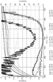
The transmission spectra of standard tenter, parabolic tenter, and multilayer comparative polarizer performance with and without crosslinker are compared in fig. 7,8, and 9, respectively. The transmission spectra of the standard tentering process are depicted in fig. 7 (comparative examples 1-4 vs comparative example 6). From this figure, it is noted that there is little difference in adding the cross-linker to the resulting spectrum. The transmission spectra of comparative polarizer performance with and without crosslinker for the parabolic tentering process (examples 1-4 versus comparative example 5) are depicted in fig. 8. For these samples prepared with the parabolic tentering process, there was a clear difference from the addition of the crosslinking agent to the formulation. The transmission spectra for comparative polarizer performance with and without crosslinker for the multilayer film case (example 5 versus comparative example 7) are depicted in fig. 9.
The optical performance properties of the examples are summarized in table 5. The results of comparative examples 1 to 4 and 6 show that there is little difference from adding a cross-linking agent when using a standard/conventional drawing process. In contrast, the results of comparative examples 1 to 4 and 5 show a significant effect of the addition of the crosslinking agent on the transmission in the light transmission state (minimum Tb%) and the polarization efficiency (maximum PE%).
Table 5: optical performance Properties


Unless otherwise indicated, descriptions with respect to elements in the figures should be understood to apply equally to corresponding elements in other figures. Although specific embodiments have been illustrated and described herein, it will be appreciated by those of ordinary skill in the art that a variety of alternate and/or equivalent implementations may be substituted for the specific embodiments shown and described without departing from the scope of the present disclosure. This application is intended to cover any adaptations or variations of the specific embodiments discussed herein. Accordingly, the disclosure is intended to be limited only by the claims and the equivalents thereof.
Claims (19)
1. A polarizer comprising an oriented first polymer layer preparable from a mixture comprising polyvinyl alcohol and a crosslinking agent, the crosslinking agent being contained in the mixture at a content of 5 to 40 wt% based on the total weight of the polyvinyl alcohol and the crosslinking agent, wherein the oriented first polymer layer is a substantially uniaxially stretched layer, wherein U ═ 1/MDDR-1)/(TDDR1/2-1), U is at least 0.85, MDDR is machine direction stretch ratio, and TDDR is cross direction stretch ratio; the oriented first polymer layer has a minimum transmission of less than 0.1% for normally incident light in a wavelength range of 540nm to 640nm polarized along a block axis and a maximum transmission of at least 75% for normally incident light in a wavelength range of 540nm to 640nm polarized along a pass axis orthogonal to the block axis.
2. The polarizer of claim 1, wherein the oriented first polymer layer comprises a dichroic material.
3. The polarizer of claim 1, further comprising a second layer, wherein the oriented first polymer layer is disposed on the second layer.
4. The polarizer of claim 3, wherein the second layer comprises a polymeric multilayer optical film.
5. The polarizer of claim 4, wherein the polymeric multilayer optical film comprises a reflective polarizer.
6. The polarizer of claim 5, wherein the polymeric multilayer optical film comprises at least one dichroic layer.
7. The polarizer of claim 5, wherein a retarder is disposed on the polymeric multilayer optical film opposite the oriented first polymer layer.
8. The polarizer of claim 1, wherein the cross-linking agent comprises one or more formaldehyde adducts.
9. The polarizer of claim 1, wherein the cross-linking agent comprises melamine formaldehyde and is included in the mixture at a content of 5 to 30 wt%.
10. The polarizer according to claim 1, wherein the crosslinking agent includes urea formaldehyde, and is contained in the mixture at a content of 5 to 30 wt%.
11. A display comprising the polarizer according to any one of claims 1 to 10 as a first polarizer.
12. A method of manufacturing a polarizer comprising an oriented first polymer layer, the method comprising:
forming a mixture of polyvinyl alcohol and a crosslinking agent in a solvent, a quotient of a weight of the crosslinking agent contained in the mixture divided by a sum of the weight of the crosslinking agent and the weight of the polyvinyl alcohol being in a range of 0.05 to 0.3;
applying the mixture to a second layer;
drying the mixture to remove the solvent, thereby forming a dried coating;
stretching the coated second layer to orient the dried coating layer to form the oriented first polymer layer,
wherein stretching the coated second layer comprises conveying the coated second layer in a machine direction within a stenter while maintaining opposing edge portions of the coated second layer, and stretching the coated second layer within the stenter by moving the opposing edge portions along diverging non-linear paths;
the stretching step comprises stretching the coated second layer in the machine direction at a stretch ratio of MDDR, and stretching the coated second layer in the cross direction at a stretch ratio of TDDR, wherein U ═ 1/MDDR-1)/(TDDR1/2-1) is at least 0.85; and
the oriented first polymer layer has a minimum transmission of less than 0.1% for normally incident light in a wavelength range of 540nm to 640nm polarized along a block axis and a maximum transmission of at least 75% for normally incident light in a wavelength range of 540nm to 640nm polarized along a pass axis orthogonal to the block axis.
13. The method of claim 12, wherein the non-linear path is a parabolic path.
14. The method of claim 12, wherein the mixture further comprises a dichroic dye.
15. The method of claim 12, wherein the drying is performed at a temperature in the range of 25 ℃ to 180 ℃.
16. The method of claim 12, wherein the stretching is performed at a temperature in the range of 25 ℃ to 180 ℃.
17. The method of claim 12, wherein the mixture is at a temperature above 150 ℃ for no more than 5 minutes prior to stretching.
18. The method of claim 12, wherein the crosslinking agent comprises one or more formaldehyde adducts.
19. The method of claim 12, wherein the second layer comprises a plurality of alternating polymer layers, and wherein after the stretching step, the second layer comprises a reflective polarizer.
Applications Claiming Priority (3)
| Application Number | Priority Date | Filing Date | Title |
|---|---|---|---|
| US201662375479P | 2016-08-16 | 2016-08-16 | |
| US62/375,479 | 2016-08-16 | ||
| PCT/US2017/045305 WO2018034854A1 (en) | 2016-08-16 | 2017-08-03 | Polarizer |
Publications (2)
| Publication Number | Publication Date |
|---|---|
| CN109642974A CN109642974A (en) | 2019-04-16 |
| CN109642974B true CN109642974B (en) | 2022-04-15 |
Family
ID=61197103
Family Applications (1)
| Application Number | Title | Priority Date | Filing Date |
|---|---|---|---|
| CN201780050318.2A Active CN109642974B (en) | 2016-08-16 | 2017-08-03 | Polarizer |
Country Status (6)
| Country | Link |
|---|---|
| US (1) | US11231536B2 (en) |
| JP (1) | JP7117288B2 (en) |
| KR (1) | KR20190032605A (en) |
| CN (1) | CN109642974B (en) |
| TW (1) | TW201821275A (en) |
| WO (1) | WO2018034854A1 (en) |
Families Citing this family (1)
| Publication number | Priority date | Publication date | Assignee | Title |
|---|---|---|---|---|
| KR102620957B1 (en) * | 2020-07-10 | 2024-01-03 | 삼성에스디아이 주식회사 | Optical film, polarizing plate comprising the same and optical display apparatus comprising the same |
Citations (9)
| Publication number | Priority date | Publication date | Assignee | Title |
|---|---|---|---|---|
| JP2003307623A (en) * | 2002-04-18 | 2003-10-31 | Kuraray Co Ltd | Polarizing plate |
| CN1635948A (en) * | 2001-05-31 | 2005-07-06 | 3M创新有限公司 | Processes and apparatus for making transversely drawn films with substantially uniaxial character |
| TW200609542A (en) * | 2004-09-15 | 2006-03-16 | Far Eastern Textile Ltd | Optical compensator for a liquid crystal display |
| CN101137917A (en) * | 2005-03-10 | 2008-03-05 | 日本化药株式会社 | Iodine-containing polarizing film, process for producing the same, and polarizer comprising the same |
| CN101163997A (en) * | 2005-04-22 | 2008-04-16 | 富士胶片株式会社 | Optical film, polarizing plate and liquid crystal display |
| CN101868742A (en) * | 2007-11-30 | 2010-10-20 | 日东电工株式会社 | Polarizer, process for producing the same, optical film, and image display |
| CN103091760A (en) * | 2011-11-07 | 2013-05-08 | 第一毛织株式会社 | Polarizer having enhanced photodurability and method for preparing the same |
| CN103261928A (en) * | 2010-12-09 | 2013-08-21 | 住友化学株式会社 | Methods for producing polarizing laminate film and polarizing plate |
| CN104995536A (en) * | 2013-02-20 | 2015-10-21 | 3M创新有限公司 | Absorbing, reflecting and collimating polarizer stack and backlights incorporating same |
Family Cites Families (34)
| Publication number | Priority date | Publication date | Assignee | Title |
|---|---|---|---|---|
| US4166871A (en) | 1977-06-29 | 1979-09-04 | Polaroid Corporation | Iodine stained light polarizer |
| US4659523A (en) | 1984-11-30 | 1987-04-21 | American Hoechst Corporation | Production of iodine stainable polyester polarizer film |
| US4895769A (en) | 1988-08-09 | 1990-01-23 | Polaroid Corporation | Method for preparing light polarizer |
| US5066108A (en) | 1989-12-22 | 1991-11-19 | Hughes Aircraft Company | High throughput contrast enhancement for polarized displays |
| US5882774A (en) | 1993-12-21 | 1999-03-16 | Minnesota Mining And Manufacturing Company | Optical film |
| US6096375A (en) | 1993-12-21 | 2000-08-01 | 3M Innovative Properties Company | Optical polarizer |
| US6111697A (en) | 1998-01-13 | 2000-08-29 | 3M Innovative Properties Company | Optical device with a dichroic polarizer and a multilayer optical film |
| US6549335B1 (en) | 2000-07-28 | 2003-04-15 | 3M Innovative Properties Company | High durability circular polarizer for use with emissive displays |
| JP2004507781A (en) | 2000-08-21 | 2004-03-11 | スリーエム イノベイティブ プロパティズ カンパニー | Loss enhanced reflected light filter |
| US6814899B2 (en) | 2002-02-12 | 2004-11-09 | 3M Innovative Properties Company | Enhanced K-type polarizer |
| US6936960B2 (en) | 2003-01-10 | 2005-08-30 | Eastman Kodak Company | OLED displays having improved contrast |
| WO2004095091A1 (en) | 2003-04-21 | 2004-11-04 | Nitto Denko Corporation | Polarizer, method for producing same, polarizing plate, optical film and image display |
| JP4888931B2 (en) | 2003-08-08 | 2012-02-29 | 日東電工株式会社 | Method for manufacturing superimposed film for liquid crystal display device, superimposed film for liquid crystal display device, and liquid crystal display device |
| US20080192345A1 (en) | 2005-03-10 | 2008-08-14 | Noriaki Mochizuki | Iodine Polarizing Film, a Method for Producing the Same, and a Polarizing Plate Using the Same |
| US20060227421A1 (en) | 2005-04-06 | 2006-10-12 | Stover Carl A | Optical bodies including strippable boundary layers |
| JP4968669B2 (en) | 2005-07-28 | 2012-07-04 | 日本合成化学工業株式会社 | Polyvinyl alcohol film for polarizing film and polarizing film and polarizing plate using the same |
| US20070047080A1 (en) | 2005-08-31 | 2007-03-01 | 3M Innovative Properties Company | Methods of producing multilayer reflective polarizer |
| US7515231B2 (en) * | 2005-09-30 | 2009-04-07 | Teledyne Scientific & Imaging, Llc | Low temperature nematic liquid crystal alignment material and LCD compensator incorporating the liquid crystal alignment material |
| US20070228586A1 (en) | 2006-03-31 | 2007-10-04 | Merrill William W | Process for making an optical film |
| US7826009B2 (en) | 2006-12-21 | 2010-11-02 | 3M Innovative Properties Company | Hybrid polarizer |
| KR101393754B1 (en) | 2006-12-28 | 2014-05-12 | 닛토덴코 가부시키가이샤 | Process for producing polarizer, polarizer, polarizing plate, optical film, process for producing composite polarizing plate, composite polarizing plate, and image display device |
| JP5628789B2 (en) | 2008-03-31 | 2014-11-19 | スリーエム イノベイティブ プロパティズ カンパニー | Primer layer for multilayer optical film |
| JP4928529B2 (en) * | 2008-11-12 | 2012-05-09 | 日東電工株式会社 | Manufacturing method of polarizing plate, polarizing plate, optical film, and image display device |
| JPWO2010092926A1 (en) | 2009-02-13 | 2012-08-16 | 日東電工株式会社 | LAMINATED OPTICAL BODY, OPTICAL FILM, LIQUID CRYSTAL DISPLAY DEVICE USING THE OPTICAL FILM, AND METHOD FOR PRODUCING LAMINATED OPTICAL BODY |
| CN102869503B (en) | 2010-03-26 | 2014-12-17 | 3M创新有限公司 | Textured film and process for manufacture thereof |
| JP4691205B1 (en) | 2010-09-03 | 2011-06-01 | 日東電工株式会社 | Method for producing optical film laminate including thin high-performance polarizing film |
| JP5502023B2 (en) | 2010-09-03 | 2014-05-28 | 日東電工株式会社 | Method for producing optical film laminate roll having polarizing film |
| JP5478553B2 (en) | 2010-09-03 | 2014-04-23 | 日東電工株式会社 | Continuous web-like optical film laminate roll and method for producing the same |
| JP5985813B2 (en) | 2011-11-14 | 2016-09-06 | 日東電工株式会社 | Manufacturing method of polarizer, polarizer, polarizing plate, optical film, and image display device |
| JP2014205826A (en) * | 2013-03-18 | 2014-10-30 | 日本合成化学工業株式会社 | Crosslinking agent, crosslinked polymer, and their applications |
| KR20150039982A (en) | 2013-10-04 | 2015-04-14 | 동우 화인켐 주식회사 | Method for preparing polarizer and polarizer |
| JP6077619B2 (en) | 2014-09-30 | 2017-02-08 | 日東電工株式会社 | Single protective polarizing film, polarizing film with pressure-sensitive adhesive layer, image display device, and continuous production method thereof |
| KR20160080335A (en) * | 2014-12-29 | 2016-07-08 | 동우 화인켐 주식회사 | Process for Preparing Polarizer |
| EP3308201A1 (en) | 2015-06-15 | 2018-04-18 | 3M Innovative Properties Company | Optical stack including reflecting-absorbing polarizer |
-
2017
- 2017-08-03 WO PCT/US2017/045305 patent/WO2018034854A1/en active Application Filing
- 2017-08-03 KR KR1020197007171A patent/KR20190032605A/en unknown
- 2017-08-03 US US16/318,836 patent/US11231536B2/en active Active
- 2017-08-03 CN CN201780050318.2A patent/CN109642974B/en active Active
- 2017-08-03 JP JP2019508225A patent/JP7117288B2/en active Active
- 2017-08-15 TW TW106127533A patent/TW201821275A/en unknown
Patent Citations (9)
| Publication number | Priority date | Publication date | Assignee | Title |
|---|---|---|---|---|
| CN1635948A (en) * | 2001-05-31 | 2005-07-06 | 3M创新有限公司 | Processes and apparatus for making transversely drawn films with substantially uniaxial character |
| JP2003307623A (en) * | 2002-04-18 | 2003-10-31 | Kuraray Co Ltd | Polarizing plate |
| TW200609542A (en) * | 2004-09-15 | 2006-03-16 | Far Eastern Textile Ltd | Optical compensator for a liquid crystal display |
| CN101137917A (en) * | 2005-03-10 | 2008-03-05 | 日本化药株式会社 | Iodine-containing polarizing film, process for producing the same, and polarizer comprising the same |
| CN101163997A (en) * | 2005-04-22 | 2008-04-16 | 富士胶片株式会社 | Optical film, polarizing plate and liquid crystal display |
| CN101868742A (en) * | 2007-11-30 | 2010-10-20 | 日东电工株式会社 | Polarizer, process for producing the same, optical film, and image display |
| CN103261928A (en) * | 2010-12-09 | 2013-08-21 | 住友化学株式会社 | Methods for producing polarizing laminate film and polarizing plate |
| CN103091760A (en) * | 2011-11-07 | 2013-05-08 | 第一毛织株式会社 | Polarizer having enhanced photodurability and method for preparing the same |
| CN104995536A (en) * | 2013-02-20 | 2015-10-21 | 3M创新有限公司 | Absorbing, reflecting and collimating polarizer stack and backlights incorporating same |
Also Published As
| Publication number | Publication date |
|---|---|
| KR20190032605A (en) | 2019-03-27 |
| TW201821275A (en) | 2018-06-16 |
| WO2018034854A1 (en) | 2018-02-22 |
| US20190285787A1 (en) | 2019-09-19 |
| JP2019532325A (en) | 2019-11-07 |
| US11231536B2 (en) | 2022-01-25 |
| JP7117288B2 (en) | 2022-08-12 |
| CN109642974A (en) | 2019-04-16 |
Similar Documents
| Publication | Publication Date | Title |
|---|---|---|
| US6335051B1 (en) | Dichroic polarizing film and optical polarizer containing the film | |
| TWI739941B (en) | Broadband wavelength film and manufacturing method thereof, and manufacturing method of circularly polarized film | |
| KR102606109B1 (en) | Polarizing film and method of manufacturing the polarizing film | |
| WO2013129259A1 (en) | Method for producing polarizing plate | |
| JP7376494B2 (en) | Polarizing plate, method for manufacturing the same, and image display device including the polarizing plate | |
| TWI564137B (en) | A method of manufacturing a polarizing member, a polarizing member, a polarizing plate, an optical film, and an image display device | |
| JP6999059B2 (en) | Polarizing plate with retardation layer and image display device using it | |
| JP2014146035A (en) | Method for manufacturing polarizer, polarizer, polarizing plate, optical film and image display device | |
| CN109642974B (en) | Polarizer | |
| JP6797499B2 (en) | Polarizing plate with retardation layer and image display device using it | |
| JP7370177B2 (en) | Polarizing plate with retardation layer and image display device using the same | |
| TWI713881B (en) | Adhesive composition, optical laminate comprising the adhesive composition, and display device thereof | |
| CN110799333A (en) | Roll film comprising multilayer birefringent reflective polarizer and polyvinyl alcohol layer with low transmission axis variation | |
| JP6804168B2 (en) | Polarizing plate with retardation layer and image display device using it | |
| KR20190030522A (en) | Polarizing plate and light emitting diode display comprising the same | |
| CN113646677B (en) | Polarizing film, polarizing plate, and method for producing polarizing film | |
| KR102563131B1 (en) | Dyed triacetyl cellulose film, polarizing plate using the film, method for producing polarizing plate, polarizing plate with retardation layer, image display device, and image adjustment method of image display device | |
| WO2022107394A1 (en) | Phase difference layer-equipped phase difference layer-equipped polarizing plate and organic electroluminescence display device using same | |
| WO2021261277A1 (en) | Retardation-layer-equipped polarizing plate and image display device using same | |
| JP7288465B2 (en) | Polarizing plate, manufacturing method thereof, and image display device using the polarizing plate | |
| JP7311249B2 (en) | Retardation film, polarizing plate with retardation layer, and method for producing retardation film | |
| TW202400411A (en) | Optical laminate, lens, and display method | |
| KR102444609B1 (en) | Polarizing film, method of manufacturing the same and display device | |
| JP2022095799A (en) | Optical laminate | |
| JP2020115225A (en) | Polarizing plate with retardation layer, and image display device using the same |
Legal Events
| Date | Code | Title | Description |
|---|---|---|---|
| PB01 | Publication | ||
| PB01 | Publication | ||
| SE01 | Entry into force of request for substantive examination | ||
| SE01 | Entry into force of request for substantive examination | ||
| GR01 | Patent grant | ||
| GR01 | Patent grant |