KR20180136282A - Compressor having centrifugation and differential pressure structure for oil supplying - Google Patents
Compressor having centrifugation and differential pressure structure for oil supplying Download PDFInfo
- Publication number
- KR20180136282A KR20180136282A KR1020170075041A KR20170075041A KR20180136282A KR 20180136282 A KR20180136282 A KR 20180136282A KR 1020170075041 A KR1020170075041 A KR 1020170075041A KR 20170075041 A KR20170075041 A KR 20170075041A KR 20180136282 A KR20180136282 A KR 20180136282A
- Authority
- KR
- South Korea
- Prior art keywords
- oil
- scroll
- fixed scroll
- supply passage
- main frame
- Prior art date
- Legal status (The legal status is an assumption and is not a legal conclusion. Google has not performed a legal analysis and makes no representation as to the accuracy of the status listed.)
- Ceased
Links
Images


Classifications
-
- F—MECHANICAL ENGINEERING; LIGHTING; HEATING; WEAPONS; BLASTING
- F04—POSITIVE - DISPLACEMENT MACHINES FOR LIQUIDS; PUMPS FOR LIQUIDS OR ELASTIC FLUIDS
- F04C—ROTARY-PISTON, OR OSCILLATING-PISTON, POSITIVE-DISPLACEMENT MACHINES FOR LIQUIDS; ROTARY-PISTON, OR OSCILLATING-PISTON, POSITIVE-DISPLACEMENT PUMPS
- F04C29/00—Component parts, details or accessories of pumps or pumping installations, not provided for in groups F04C18/00 - F04C28/00
- F04C29/02—Lubrication; Lubricant separation
-
- F—MECHANICAL ENGINEERING; LIGHTING; HEATING; WEAPONS; BLASTING
- F04—POSITIVE - DISPLACEMENT MACHINES FOR LIQUIDS; PUMPS FOR LIQUIDS OR ELASTIC FLUIDS
- F04C—ROTARY-PISTON, OR OSCILLATING-PISTON, POSITIVE-DISPLACEMENT MACHINES FOR LIQUIDS; ROTARY-PISTON, OR OSCILLATING-PISTON, POSITIVE-DISPLACEMENT PUMPS
- F04C18/00—Rotary-piston pumps specially adapted for elastic fluids
- F04C18/02—Rotary-piston pumps specially adapted for elastic fluids of arcuate-engagement type, i.e. with circular translatory movement of co-operating members, each member having the same number of teeth or tooth-equivalents
- F04C18/0207—Rotary-piston pumps specially adapted for elastic fluids of arcuate-engagement type, i.e. with circular translatory movement of co-operating members, each member having the same number of teeth or tooth-equivalents both members having co-operating elements in spiral form
- F04C18/0215—Rotary-piston pumps specially adapted for elastic fluids of arcuate-engagement type, i.e. with circular translatory movement of co-operating members, each member having the same number of teeth or tooth-equivalents both members having co-operating elements in spiral form where only one member is moving
-
- F—MECHANICAL ENGINEERING; LIGHTING; HEATING; WEAPONS; BLASTING
- F04—POSITIVE - DISPLACEMENT MACHINES FOR LIQUIDS; PUMPS FOR LIQUIDS OR ELASTIC FLUIDS
- F04C—ROTARY-PISTON, OR OSCILLATING-PISTON, POSITIVE-DISPLACEMENT MACHINES FOR LIQUIDS; ROTARY-PISTON, OR OSCILLATING-PISTON, POSITIVE-DISPLACEMENT PUMPS
- F04C18/00—Rotary-piston pumps specially adapted for elastic fluids
- F04C18/02—Rotary-piston pumps specially adapted for elastic fluids of arcuate-engagement type, i.e. with circular translatory movement of co-operating members, each member having the same number of teeth or tooth-equivalents
- F04C18/0207—Rotary-piston pumps specially adapted for elastic fluids of arcuate-engagement type, i.e. with circular translatory movement of co-operating members, each member having the same number of teeth or tooth-equivalents both members having co-operating elements in spiral form
- F04C18/0246—Details concerning the involute wraps or their base, e.g. geometry
- F04C18/0269—Details concerning the involute wraps
- F04C18/0292—Ports or channels located in the wrap
-
- F—MECHANICAL ENGINEERING; LIGHTING; HEATING; WEAPONS; BLASTING
- F04—POSITIVE - DISPLACEMENT MACHINES FOR LIQUIDS; PUMPS FOR LIQUIDS OR ELASTIC FLUIDS
- F04C—ROTARY-PISTON, OR OSCILLATING-PISTON, POSITIVE-DISPLACEMENT MACHINES FOR LIQUIDS; ROTARY-PISTON, OR OSCILLATING-PISTON, POSITIVE-DISPLACEMENT PUMPS
- F04C23/00—Combinations of two or more pumps, each being of rotary-piston or oscillating-piston type, specially adapted for elastic fluids; Pumping installations specially adapted for elastic fluids; Multi-stage pumps specially adapted for elastic fluids
- F04C23/008—Hermetic pumps
-
- F—MECHANICAL ENGINEERING; LIGHTING; HEATING; WEAPONS; BLASTING
- F04—POSITIVE - DISPLACEMENT MACHINES FOR LIQUIDS; PUMPS FOR LIQUIDS OR ELASTIC FLUIDS
- F04C—ROTARY-PISTON, OR OSCILLATING-PISTON, POSITIVE-DISPLACEMENT MACHINES FOR LIQUIDS; ROTARY-PISTON, OR OSCILLATING-PISTON, POSITIVE-DISPLACEMENT PUMPS
- F04C29/00—Component parts, details or accessories of pumps or pumping installations, not provided for in groups F04C18/00 - F04C28/00
- F04C29/02—Lubrication; Lubricant separation
- F04C29/023—Lubricant distribution through a hollow driving shaft
-
- F—MECHANICAL ENGINEERING; LIGHTING; HEATING; WEAPONS; BLASTING
- F04—POSITIVE - DISPLACEMENT MACHINES FOR LIQUIDS; PUMPS FOR LIQUIDS OR ELASTIC FLUIDS
- F04C—ROTARY-PISTON, OR OSCILLATING-PISTON, POSITIVE-DISPLACEMENT MACHINES FOR LIQUIDS; ROTARY-PISTON, OR OSCILLATING-PISTON, POSITIVE-DISPLACEMENT PUMPS
- F04C29/00—Component parts, details or accessories of pumps or pumping installations, not provided for in groups F04C18/00 - F04C28/00
- F04C29/02—Lubrication; Lubricant separation
- F04C29/028—Means for improving or restricting lubricant flow
-
- F—MECHANICAL ENGINEERING; LIGHTING; HEATING; WEAPONS; BLASTING
- F04—POSITIVE - DISPLACEMENT MACHINES FOR LIQUIDS; PUMPS FOR LIQUIDS OR ELASTIC FLUIDS
- F04C—ROTARY-PISTON, OR OSCILLATING-PISTON, POSITIVE-DISPLACEMENT MACHINES FOR LIQUIDS; ROTARY-PISTON, OR OSCILLATING-PISTON, POSITIVE-DISPLACEMENT PUMPS
- F04C2240/00—Components
- F04C2240/30—Casings or housings
-
- F—MECHANICAL ENGINEERING; LIGHTING; HEATING; WEAPONS; BLASTING
- F04—POSITIVE - DISPLACEMENT MACHINES FOR LIQUIDS; PUMPS FOR LIQUIDS OR ELASTIC FLUIDS
- F04C—ROTARY-PISTON, OR OSCILLATING-PISTON, POSITIVE-DISPLACEMENT MACHINES FOR LIQUIDS; ROTARY-PISTON, OR OSCILLATING-PISTON, POSITIVE-DISPLACEMENT PUMPS
- F04C2240/00—Components
- F04C2240/50—Bearings
-
- F—MECHANICAL ENGINEERING; LIGHTING; HEATING; WEAPONS; BLASTING
- F04—POSITIVE - DISPLACEMENT MACHINES FOR LIQUIDS; PUMPS FOR LIQUIDS OR ELASTIC FLUIDS
- F04C—ROTARY-PISTON, OR OSCILLATING-PISTON, POSITIVE-DISPLACEMENT MACHINES FOR LIQUIDS; ROTARY-PISTON, OR OSCILLATING-PISTON, POSITIVE-DISPLACEMENT PUMPS
- F04C2240/00—Components
- F04C2240/60—Shafts
- F04C2240/603—Shafts with internal channels for fluid distribution, e.g. hollow shaft
Landscapes
- Engineering & Computer Science (AREA)
- Mechanical Engineering (AREA)
- General Engineering & Computer Science (AREA)
- Rotary Pumps (AREA)
- Applications Or Details Of Rotary Compressors (AREA)
Abstract
본 발명은 저유 공간에 저장된 오일을 회전축을 통해 상부로 공급하여 압축부 급유 및 베어링부 윤활을 가능하게 하는 스크롤 압축기에 관한 것이다. 또한 본 발명의 일 실시예에 따른 스크롤 압축기는, 하부의 저유 공간에 오일이 저장되는 케이싱, 케이싱의 내부 공간에 구비되는 구동 모터, 구동 모터에 결합되고, 케이싱의 저유 공간에 담긴 오일을 상부로 안내하도록 오일 공급 유로가 구비되며, 오일 공급 유로에서 외주면으로 관통된 오일 홀이 구비되는 회전축, 구동 모터의 하부에 구비되는 메인 프레임, 메인 프레임의 하부에 구비되는 고정 스크롤 및 메인 프레임과 고정 스크롤 사이에 구비되며, 고정 스크롤과 압축실을 형성하도록 고정 스크롤에 맞물려 선회 운동하는 선회 스크롤을 포함하되, 메인 프레임, 고정스크롤 및 선회스크롤 사이에는 중간압실이 형성되고, 선회 스크롤의 상면에는 오일 홀을 통해 토출된 오일을 중간압실로 안내하기 위한 포켓 홈이 형성되고, 고정 스크롤에는 중간압실로 안내된 오일을 압축실로 안내하기 위한 차압 급유 유로가 구비된다.BACKGROUND OF THE INVENTION 1. Field of the Invention [0001] The present invention relates to a scroll compressor which supplies oil stored in a low oil space to an upper portion through a rotary shaft to lubricate a compression portion and lubricate a bearing portion. According to another aspect of the present invention, there is provided a scroll compressor including: a casing in which oil is stored in a lower oil storage space; a drive motor provided in an internal space of the casing; A main shaft provided at a lower portion of the driving motor, a fixed scroll provided at a lower portion of the main frame, and a fixed scroll provided at a lower portion of the main frame, And an orbiting scroll that is pivotally engaged with the fixed scroll to form a fixed scroll and a compression chamber, wherein an intermediate pressure chamber is formed between the main frame, the fixed scroll, and the orbiting scroll, and the upper surface of the orbiting scroll A pocket groove for guiding the discharged oil to the intermediate pressure chamber is formed, and in the fixed scroll, The differential pressure fuel supply passage is provided for guiding the compression chamber to a pressure chamber guiding the oil.
Description
본 발명은 저유 공간에 저장된 오일을 회전축을 통해 상부로 공급하여 압축부 급유 및 베어링부 윤활을 가능하게 하는 원심 및 차압 급유 구조가 구비된 압축기에 관한 것이다.BACKGROUND OF THE
일반적으로 압축기는 냉장고나 에어콘과 같은 증기압축식 냉동사이클(이하, 냉동사이클로 약칭함)에 적용되고 있다.Generally, a compressor is applied to a vapor compression type refrigeration cycle such as a refrigerator or an air conditioner (hereinafter abbreviated as a refrigeration cycle).
압축기는 냉매를 압축하는 방식에 따라 왕복동식, 로터리식, 스크롤식 등으로 구분될 수 있다.Compressors can be divided into reciprocating, rotary, and scroll types depending on the method of compressing the refrigerant.
이 중 스크롤 압축기는 밀폐용기의 내부공간에 고정된 고정 스크롤에 선회 스크롤이 맞물려 선회운동을 함으로써 고정 스크롤의 고정랩과 선회 스크롤의 선회랩 사이에 압축실이 형성되는 압축기이다. The scroll compressor is a compressor in which the orbiting scroll is engaged with the fixed scroll fixed to the inner space of the hermetically sealed container, thereby forming a compression chamber between the fixed lap of the fixed scroll and the orbiting lap of the orbiting scroll.
스크롤 압축기는 다른 종류의 압축기에 비하여 상대적으로 높은 압축비를 얻을 수 있고, 냉매의 흡입, 압축, 토출 행정이 부드럽게 이어져 안정적인 토크를 얻을 수 있는 장점 때문에 공조장치 등에서 냉매압축용으로 널리 사용되고 있다.The scroll compressor is widely used for compressing refrigerant in an air conditioner or the like because it can obtain a relatively high compression ratio as compared with other types of compressors and can obtain a stable torque by smoothly connecting suction, compression, and discharge strokes of the refrigerant.
이러한 스크롤 압축기는 구동 모터와 압축부의 위치에 따라 상부 압축식 또는 하부 압축식으로 구분될 수 있다. 상부 압축식은 압축부가 구동 모터보다 상측에 위치하는 방식이고, 하부 압축식은 압축부가 구동 모터보다 하측에 위치하는 방식이다.The scroll compressor may be classified into an upper compression type or a lower compression type according to the position of the driving motor and the compression portion. The upper compression method is a method in which the compression part is located above the drive motor, and the lower compression method is a compression method in which the compression part is located below the drive motor.
여기에서, 하부 압축식 스크롤 압축기의 경우에는 저유 공간과 압축부 사이의 거리가 짧아 상대적으로는 균일한 오일공급이 가능하지만 구조적으로 오일 공급이 어려울 수도 있다.Here, in the case of the lower compression scroll compressor, since the distance between the oil storage space and the compression portion is short, a relatively uniform oil supply is possible, but structurally oil supply may be difficult.
특히, 저속에서 고속까지 다양한 속도로 구동되는 하부 압축식 스크롤 압축기의 경우, 급유량에 따른 성능 최적화와 베어링부의 신뢰성 확보가 중요하다.Particularly, in the case of a lower compression scroll compressor driven at various speeds from low speed to high speed, it is important to optimize performance according to the amount of oil supply and to secure the reliability of the bearing part.
따라서, 구조적으로 오일 공급이 어려운 부분(예를 들어, 베어링면 또는 압축실)에 대한 급유 구조 개선이 필요하다. Therefore, it is necessary to improve the oil supply structure to a part where structural oil supply is difficult (for example, a bearing surface or a compression chamber).
본 발명의 목적은 저유 공간에 담긴 오일을 회전축을 이용한 원심 급유 구조를 통해 베어링부에 원활하게 공급할 수 있는 스크롤 압축기를 제공하는 것이다.An object of the present invention is to provide a scroll compressor capable of smoothly supplying oil contained in a low-temperature space to a bearing portion through a centrifugal refueling structure using a rotary shaft.
또한 본 발명의 다른 목적은 저유 공간에 담긴 오일을 다양한 차압 급유 구조를 통해 압축실에 원활하게 공급할 수 있는 스크롤 압축기를 제공하는 것이다. Another object of the present invention is to provide a scroll compressor capable of smoothly supplying oil contained in a low oil space to a compression chamber through various differential pressure oil supply structures.
본 발명의 목적들은 이상에서 언급한 목적으로 제한되지 않으며, 언급되지 않은 본 발명의 다른 목적 및 장점들은 하기의 설명에 의해서 이해될 수 있고, 본 발명의 실시예에 의해 보다 분명하게 이해될 것이다. 또한, 본 발명의 목적 및 장점들은 특허 청구 범위에 나타낸 수단 및 그 조합에 의해 실현될 수 있음을 쉽게 알 수 있을 것이다.The objects of the present invention are not limited to the above-mentioned objects, and other objects and advantages of the present invention which are not mentioned can be understood by the following description and more clearly understood by the embodiments of the present invention. It will also be readily apparent that the objects and advantages of the invention may be realized and attained by means of the instrumentalities and combinations particularly pointed out in the appended claims.
본 발명에 따른 스크롤 압축기는 케이싱의 저유 공간에 담긴 오일을 상부로 안내하는 오일 공급 유로와 오일 공급 유로에서 회전축의 외주면으로 관통된 오일 홀을 포함함으로써 베어링부에 원활하게 오일을 공급할 수 있다.The scroll compressor according to the present invention can smoothly supply oil to the bearing portion by including an oil supply passage for guiding the oil contained in the oil storage space of the casing to the upper portion and an oil hole penetrating the outer circumferential surface of the rotary shaft in the oil supply passage.
또한 본 발명에 따른 스크롤 압축기는 차압 급유 유로를 통해 중간압실과 압축실이 연통된 차압 급유 구조 또는 중간압실을 우회하여 압축실로 오일을 공급할 수 있도록 차압 급유 유로가 구비된 차압 급유 구조를 포함함으로써 압축실에 원활하게 오일을 공급할 수 있다.Further, the scroll compressor according to the present invention includes a differential pressure lubrication structure in which the intermediate pressure chamber and the compression chamber communicate with each other through the differential pressure supply oil passage, or a differential pressure lubrication structure including a differential pressure oil supply passage for bypassing the intermediate pressure chamber, The oil can be smoothly supplied to the yarn.
본 발명에 따른 스크롤 압축기는 저유 공간에 담긴 오일을 회전축을 이용한 원심 급유 구조를 통해 베어링부에 원활하게 공급함으로써 베어링부의 마모를 방지할 수 있다. 또한 베어링부의 마모를 방지함으로써 베어링부의 신뢰성도 확보할 수 있다.The scroll compressor according to the present invention can smoothly supply the oil contained in the oil storage space to the bearing portion through the centrifugal oiling structure using the rotation shaft, thereby preventing wear of the bearing portion. Also, by preventing wear of the bearing portion, reliability of the bearing portion can be secured.
또한 본 발명에 따른 스크롤 압축기는 저유 공간에 담긴 오일을 다양한 차압 급유 구조를 통해 압축실에 원활하게 공급함으로써 선회 스크롤과 고정 스크롤 간 마찰에 따른 마모를 저감할 수 있고, 압축 효율을 개선할 수 있다. Further, the scroll compressor according to the present invention can smoothly supply the oil contained in the oil storage space to the compression chamber through the various differential pressure oil supply structures, thereby reducing wear due to friction between the orbiting scroll and the fixed scroll, and improving the compression efficiency .
상술한 효과와 더불어 본 발명의 구체적인 효과는 이하 발명을 실시하기 위한 구체적인 사항을 설명하면서 함께 기술한다. The above and other objects, features and advantages of the present invention will be more apparent from the following detailed description taken in conjunction with the accompanying drawings, in which: FIG.
도 1은 본 발명의 실시예에 따른 스크롤 압축기를 설명하는 단면도이다.
도 2 및 도 3은 도 1의 스크롤 압축기의 급유 구조의 일 예를 설명하는 개략도들이다.
도 4 및 도 5는 도 1의 스크롤 압축기의 급유 구조의 다른 예를 설명하는 개략도들이다.
도 6 및 도 7은 도 1의 스크롤 압축기의 급유 구조의 또 다른 예를 설명하는 개략도들이다. 1 is a cross-sectional view illustrating a scroll compressor according to an embodiment of the present invention.
Figs. 2 and 3 are schematic views for explaining an example of the oil supply structure of the scroll compressor of Fig. 1. Fig.
Fig. 4 and Fig. 5 are schematic views for explaining another example of the oil supply structure of the scroll compressor of Fig.
Figs. 6 and 7 are schematic views for explaining another example of the oil supply structure of the scroll compressor of Fig.
이하, 첨부된 도면을 참조하여 본 발명에 따른 바람직한 실시예를 상세히 설명하기로 한다. 도면에서 동일한 참조부호는 동일 또는 유사한 구성요소를 가리키는 것으로 사용된다.Hereinafter, preferred embodiments of the present invention will be described in detail with reference to the accompanying drawings. In the drawings, the same reference numerals are used to denote the same or similar elements.
이하에서는, 도 1을 참조하여, 본 발명의 실시예에 따른 스크롤 압축기를 설명하도록 한다.Hereinafter, a scroll compressor according to an embodiment of the present invention will be described with reference to FIG.
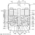
도 1은 본 발명의 실시예에 따른 스크롤 압축기를 설명하는 단면도이다. 1 is a cross-sectional view illustrating a scroll compressor according to an embodiment of the present invention.
본 발명의 실시예에 따른 스크롤 압축기는 내부공간을 갖는 케이싱(210), 내부공간의 상부에 구비되는 구동 모터(220), 구동 모터(220)의 하단에 배치되는 압축부(200), 구동 모터(220)의 구동력을 압축부(200)로 전달하는 회전축(226)을 포함할 수 있다. The scroll compressor according to the embodiment of the present invention includes a
여기에서, 케이싱(210)의 내부공간은 구동 모터(220)의 상측인 제1 공간(V1), 구동 모터(220)와 압축부(200)의 사이인 제2 공간(V2), 토출커버(270)에 의해 구획된 제3 공간(V3) 및 압축부(200)의 하측인 저유 공간(V4)으로 구획될 수 있다.The internal space of the
케이싱(210)은 예를 들어, 원통형의 형상일 수 있고, 이에 따라, 케이싱(210)은 원통 쉘(211)을 포함할 수 있다.The
또한 원통 쉘(211)의 상부에는 상부 쉘(212)이 설치되고, 원통 쉘(211)의 하부에는 하부 쉘(214)이 설치될 수 있다. 상부 및 하부 쉘(212, 214)은 예를 들어, 용접으로 원통 쉘(211)에 결합되어 내부공간을 형성할 수 있다.An
여기에서, 상부 쉘(212)에는 냉매 토출관(216)이 설치될 수 있는데, 냉매 토출관(216)은 압축부(200)에서 제2 공간(V2)과 제1 공간(V1)으로 토출되는 압축된 냉매가 외부로 배출되는 통로이다. Here, the
참고로, 토출되는 냉매에 혼입된 오일을 분리하는 오일 세퍼레이터(미도시)가 냉매 토출관(216)과 연결될 수 있다.An oil separator (not shown) may be connected to the
하부 쉘(214)은 오일을 저장할 수 있는 저유 공간(V4)을 형성할 수 있다.The
저유 공간(V4)은 압축기가 원활하게 작동될 수 있도록 압축부(200)에 오일을 공급하는 오일챔버로서의 기능을 수행할 수 있다.The oil storage space V4 can function as an oil chamber for supplying oil to the compression unit 200 so that the compressor can be smoothly operated.
또한 원통 쉘(211)의 측면에는 압축될 냉매가 유입되는 통로인 냉매 흡입관(218)이 설치될 수 있다. Further, a
냉매 흡입관(218)은 고정 스크롤(250)의 측면을 따라 압축실(S1)까지 관통되어 설치될 수 있다.The
이러한 케이싱(210) 내측의 상부에는 구동 모터(220)가 설치될 수 있다.A
구체적으로, 구동 모터(220)는 고정자(222) 및 회전자(224)를 포함할 수 있다.Specifically, the
고정자(222)는 예를 들어, 원통형일 수 있으며, 케이싱(210)에 고정될 수 있다. 고정자(222)는 그 내주면에 원주방향을 따라 다수 개의 슬롯(미도시)이 형성되어 코일(222a)이 권선된다. 또한 고정자(222)의 외주면에는 디컷(D-cut) 모양으로 절단되어 압축부(200)에서 토출되는 냉매 또는 오일이 통과하도록 냉매유로홈(212a)이 형성될 수 있다.The
회전자(224)는 고정자(222)의 내부에 결합되고, 회전동력을 발생시킬 수 있다. 즉, 회전자(224)는 그 중심에 회전축(226)이 압입되어 회전축(226)과 함께 회전운동할 수 있다. 회전자(224)에 의해 발생된 회전동력은 회전축(226)을 통하여 압축부(200)에 전달된다.The
압축부(200)는 메인 프레임(230), 고정 스크롤(250), 선회 스크롤(240) 및 토출 커버(270)를 포함할 수 있다.The compression unit 200 may include a
참고로, 압축부(200)는 올담링(Oldham's ring)(150)을 더 구비할 수 있다. 올담링(150)은 선회 스크롤(240)과 메인 프레임(230) 사이에 설치될 수 있다. 또한 올담링(150)은 선회 스크롤(240)의 자전을 방지하면서 고정 스크롤(250) 상에서의 선회 스크롤(240)의 선회 운동을 가능하게 한다.For reference, the compression unit 200 may further include an Oldham's
메인 프레임(230)은 구동 모터(220)의 하부에 구비되고, 압축부(200)의 상부를 형성할 수 있다.The
메인 프레임(230)에는 대략 원형을 갖는 프레임 경판부(이하, 제1 경판부)(232), 제1 경판부(232)의 중앙에 구비되고 회전축(226)이 관통하는 프레임 축수부(이하, 제1 축수부)(232a), 및 제1 경판부(232)의 외주부에서 하부로 돌출되는 프레임 측벽부(이하, 제1 측벽부)(231)가 구비될 수 있다.The
제1 측벽부(231)는 외주부가 원통 쉘(211)의 내주면과 접하고, 하단부가 후술할 고정 스크롤 측벽부(255)의 상단부와 접할 수 있다.The outer peripheral portion of the
제1 측벽부(231)에는 제1 측벽부(231)의 내부를 축 방향으로 관통하여 냉매 통로를 이루는 프레임 토출공(이하, 제1 토출공)(231a)이 구비될 수 있다. 제1 토출공(231a)은 입구가 후술할 고정 스크롤 토출공(256b)의 출구와 연통되고, 출구가 제2 공간(V2)과 연통될 수 있다.The first
제1 축수부(232a)는 제1 경판부(232)의 상면에서 구동 모터(220) 측으로 돌출 형성될 수 있다. 또한 제1 축수부(232a)에는 후술할 회전축(226)의 메인 베어링부(226c)가 관통 지지되도록 제1 베어링부가 형성될 수 있다.The first bearing
즉, 메인 프레임(230)의 중심에는 제1 베어링부를 이루는 회전축(226)의 메인 베어링부(226c)가 회전 가능하게 삽입되어 지지되는 제1 축수부(232a)가 축방향으로 관통 형성될 수 있다. That is, a
제1 경판부(232)의 상면에는 제1 축수부(232a)와 회전축(226) 사이에서 토출되는 오일을 포집하는 오일포켓(232b)이 형성될 수 있다.An
오일포켓(232b)은 제1 경판부(232)의 상면에 음각지게 형성되고, 제1 축수부(232a)의 외주면을 따라 환형으로 형성될 수 있다. 또한 메인 프레임(230)의 저면에는 고정 스크롤(250) 및 선회 스크롤(240)과 함께 공간을 형성하여 그 공간의 압력에 의해 선회 스크롤(240)을 지지하도록 배압실(S2)이 형성될 수 있다.The
참고로, 배압실(S2)은 중간압 영역(즉, 중간압실)을 포함할 수 있고, 회전축(226)에 구비된 오일 공급 유로(226a)는 배압실(S2)보다 압력이 높은 고압 영역을 포함할 수 있다. For example, the back pressure chamber S2 may include an intermediate pressure region (i.e., an intermediate pressure chamber), and the oil supply passage 226a provided in the rotary shaft 226 may be a high pressure region higher in pressure than the back pressure chamber S2 .
이러한 고압 영역과 중간압 영역을 구분하기 위해 메인 프레임(230) 및 선회 스크롤(240) 사이에 배압 씰(seal)(280)이 구비될 수 있고, 배압 씰(280)은 예를 들어, 밀봉 부재 역할을 할 수 있다.A
또한 메인 프레임(230)은 고정 스크롤(250)과 결합하여 선회 스크롤(240)이 선회 가능하도록 설치될 수 있는 공간을 형성할 수 있다. 즉, 이러한 구조는 회전축(226)을 통해 압축부(200)에 회전동력이 전달될 수 있도록 회전축(226)을 감싸는 구조가 될 수 있다.In addition, the
메인 프레임(230)의 저면에는 제1 스크롤을 이루는 고정 스크롤(250)이 결합될 수 있다.The fixed
구체적으로, 고정 스크롤(250)은 메인 프레임(230)의 하부에 구비될 수 있다. Specifically, the fixed
또한 고정 스크롤(250)은 대략 원형을 갖는 고정 스크롤 경판부(제2 경판부)(254), 제2 경판부(254)의 외주부에서 상부로 돌출되는 고정 스크롤 측벽부(이하, 제2 측벽부)(255), 제2 경판부(254)의 상면에서 돌출되고 후술할 선회 스크롤(240)의 선회랩(241)과 맞물려 압축실(S1)을 형성하는 고정랩(251), 및 제2 경판부(254)의 배면 중앙에 형성되고 회전축(226)이 관통하는 고정 스크롤 축수부(이하, 제2 축수부)(252)를 구비할 수 있다. The fixed
제2 경판부(254)에는 압축된 냉매를 압축실(S1)로부터 토출커버(270)의 내부공간으로 안내하는 토출구(253)가 형성될 수 있다. 또한 토출구(253)의 위치는 요구되는 토출압 등을 고려하여 임의로 설정될 수 있다.The second
여기에서, 토출구(253)가 하부 쉘(214)을 향해 형성됨에 따라 고정 스크롤(250)의 저면에는, 토출되는 냉매를 수용하고 해당 냉매를 오일과 혼합되지 않게 후술할 고정 스크롤 토출공(256b)으로 안내하기 위한 토출커버(270)가 결합될 수 있다. 토출커버(270)는 냉매의 토출유로와 저유 공간(V4)을 분리할 수 있도록 고정 스크롤(250)의 저면에 밀봉 결합될 수 있다. As the
또한 토출커버(270)에는, 제2 베어링부를 이루는 회전축(226)의 서브 베어링부(226g)에 결합되어 케이싱(210)의 저유 공간(V4)에 잠기는 오일피더(271)가 관통하도록 관통구멍(276)이 형성될 수 있다.The
한편, 제2 측벽부(255)에는 그 제2 측벽부(255)의 내부를 축 방향으로 관통하여 제1 토출공(231a)과 함께 냉매 통로를 이루는 고정 스크롤 토출공(이하, 제2 토출공)(256b)이 구비될 수 있다. On the other hand, the
제2 토출공(256b)은 제1 토출공(231a)에 대응되게 형성되고, 입구가 토출커버(270)의 내부공간과 연통되고, 출구가 제1 토출공(231a)의 입구와 연통될 수 있다.The
여기에서, 제2 토출공(256b)과 제1 토출공(231a)은, 압축실(S1)에서 토출커버(270)의 내부공간으로 토출된 냉매가 제2 공간(V2)으로 안내되도록, 제3 공간(V3)과 제2 공간(V2)을 연통시킬 수 있다. The
그리고, 제2 측벽부(255)에는 냉매 흡입관(218)이 압축실(S1)의 흡입 측에 연통되도록 설치될 수 있다. 또한 냉매 흡입관(218)은 제2 토출공(256b)과 이격되게 설치될 수 있다.The second
제2 축수부(252)는 제2 경판부(254)의 하면에서 저유 공간(V4) 측으로 돌출 형성될 수 있다. The
또한 제2 축수부(252)에는 회전축(226)의 서브 베어링부(226g)가 삽입되어 지지되도록 제2 베어링부가 구비될 수 있다.The
그리고, 제2 축수부(252)는 하단부가 회전축(226)의 서브 베어링부(226g) 하단을 지지하여 스러스트 베어링면을 이루도록 축 중심을 향해 절곡될 수 있다.The lower end of the
메인 프레임(230)과 고정 스크롤(250)의 사이에는 제2 스크롤을 이루는 선회 스크롤(240)이 설치될 수 있다.The
구체적으로, 선회 스크롤(240)은 회전축(226)에 결합되어 선회운동을 하면서 고정 스크롤(250)과의 사이에 두 개 한 쌍의 압축실(S1)을 형성할 수 있다.Specifically, the
또한 선회 스크롤(240)은 대략 원형을 갖는 선회 스크롤 경판부(이하, 제3 경판부)(245), 제3 경판부(245)의 하면에서 돌출되어 고정랩(251)과 맞물리는 선회랩(241) 및 제3 경판부(245)의 중앙에 구비되고 회전축(226)의 편심부(226f)에 회전 가능하게 결합되는 회전축 결합부(242)를 포함할 수 있다.The
선회 스크롤(240)의 경우, 제3 경판부(245)의 외주부가 제2 측벽부(255)의 상단부에 위치하고, 선회랩(241)의 하단부가 제2 경판부(254)의 상면에 밀착되어, 고정 스크롤(250)에 지지될 수 있다.In the case of the
참고로, 선회 스크롤(240)의 상면에는 후술할 오일 홀(228a, 228b, 228d, 228e)을 통해 토출된 오일을 중간압실로 안내하기 위한 포켓 홈(180)이 형성될 수 있다. For reference, on the upper surface of the
구체적으로, 포켓 홈(180)은 제3 경판부(245)의 상면에 음각지게 형성될 수 있다. 즉, 포켓 홈(180)은 배압 씰(280)과 회전축(226) 사이의 제3 경판부(245)의 상면에 형성될 수 있다. Specifically, the
또한 포켓 홈(180)은 도면에 도시된 바와 같이, 회전축(226)의 양 옆에 한 개씩 형성될 수도 있지만, 회전축(226)의 양 옆에 복수개씩 형성될 수도 있다.The
포켓 홈(180)이 복수개 형성되는 경우, 복수개의 포켓 홈은 배압 씰(280)과 회전축(226) 사이의 제3 경판부(245)의 상면에 일정 간격 이격되도록 형성될 수 있다. When a plurality of
또한 포켓 홈(180)은 배압 씰(280)과 회전축(226) 사이의 제3 경판부(245)의 상면에 회전축(226)을 중심으로 환형으로 형성될 수도 있다.The
회전축 결합부(242)의 외주부는 선회랩(241)과 연결되어 압축과정에서 고정랩(251)과 함께 압축실(S1)을 형성하는 역할을 하게 된다. The outer circumferential portion of the rotary
참고로, 고정랩(251)과 선회랩(241)은 인볼류트 형상으로 형성될 수 있지만 그 외의 다양한 형상으로 형성될 수 있다.For reference, the
여기에서, 인볼류트 형상은 임의의 반경을 갖는 기초원의 주위에 감겨있는 실을 풀어낼 때 실의 단부가 그리는 궤적에 해당되는 곡선을 의미한다. Here, the involute shape means a curve corresponding to the locus drawn by the end of the thread when the thread wound around the base circle having an arbitrary radius is released.
또한 회전축 결합부(242)에는 회전축(226)의 편심부(226f)가 삽입될 수 있다. 회전축 결합부(242)에 삽입된 편심부(226f)는 선회랩(241) 또는 고정랩(251)과 압축기의 반경방향으로 중첩될 수 있다. The
여기에서, 반경방향은 축방향(즉, 상하방향)과 직교하는 방향(즉, 좌우방향)을 의미할 수 있고, 보다 구체적으로, 반경방향은 회전축의 외측에서 내측을 향하는 방향을 의미할 수 있다.Here, the radial direction may mean a direction orthogonal to the axial direction (i.e., the up-and-down direction) (that is, the left-right direction), and more specifically, the radial direction may mean a direction from the outside to the inside of the rotation shaft .
상기와 같이, 회전축(226)의 편심부(226f)가 제3 경판부(245)를 관통하여 선회랩(241)과 반경방향으로 중첩되는 경우, 냉매의 반발력과 압축력이 제3 경판부(245)를 기준으로 하여 동일 평면에 가해지면서 서로 일정 부분 상쇄될 수 있다.As described above, when the
또한 회전축(226)은 구동 모터(220)에 결합되며, 케이싱(210)의 저유 공간(V4)에 담긴 오일을 상부로 안내하기 위한 오일 공급 유로(226a)를 구비할 수 있다.The rotary shaft 226 is coupled to the driving
구체적으로, 회전축(226)은 그 상부가 회전자(224)의 중심에 압입되어 결합되고, 그 하부는 압축부(200)에 결합되어 반경방향으로 지지될 수 있다.Specifically, the upper portion of the rotary shaft 226 is press-fitted to the center of the
이로써, 회전축(226)은 구동 모터(220)의 회전력을 압축부(200)의 선회 스크롤(240)에 전달할 수 있다. 또한 이를 통해 회전축(226)에 편심 결합된 선회 스크롤(240)이 고정 스크롤(250)에 대해 선회운동을 하게 된다.Accordingly, the rotary shaft 226 can transmit the rotational force of the driving
이러한 회전축(226)의 하부에는 메인 프레임(230)의 제1 축수부(232a)에 삽입되어 반경방향으로 지지되도록 메인 베어링부(226c)가 형성될 수 있다. 또한 메인 베어링부(226c)의 하부에는 고정 스크롤(250)의 제2 축수부(252)에 삽입되어 반경방향으로 지지되도록 서브 베어링부(226g)가 형성될 수 있다. 그리고 메인 베어링부(226c)와 서브 베어링부(226g) 사이에는 선회 스크롤(240)의 회전축 결합부(242)에 삽입되어 결합되도록 편심부(226f)가 형성될 수 있다. A
메인 베어링부(226c)와 서브 베어링부(226g)는 동일 축중심을 가지도록 동축 선상에 형성되고, 편심부(226f)는 메인 베어링부(226c) 또는 서브 베어링부(226g)에 대해 반경방향으로 편심지게 형성될 수 있다. The
참고로, 편심부(226f)는 그 외경이 메인 베어링부(226c)의 외경보다는 작게, 서브 베어링부(226g)의 외경보다는 크게 형성될 수 있다. 이 경우, 회전축(226)을 각각의 축수부(232a, 252)와 회전축 결합부(242)를 통과하여 결합시키는데 유리할 수 있다. For reference, the
반면, 편심부(226f)가 회전축(226)에 일체로 형성되지 않고 별도의 베어링을 이용하여 형성될 수도 있다. 이 경우에는 서브 베어링부(226g)의 외경이 편심부(226f)의 외경보다 작게 형성되지 않고도 회전축(226)이 각각의 축수부(232a, 252)와 회전축 결합부(242)에 삽입되어 결합될 수 있다.On the other hand, the
그리고 회전축(226)의 내부에는 저유 공간(V4)의 오일을 각 베어링부(226c, 226g)의 외주면과 편심부(226f)의 외주면에 공급하기 위한 오일 공급 유로(226a)가 형성될 수 있다. 또한 회전축(226)의 베어링부 및 편심부(226c, 226g, 226f)에는 오일 공급 유로(226a)에서 외주면으로 관통되는 오일 홀(228a, 228b, 228d, 228e)이 형성될 수 있다.An oil supply passage 226a for supplying the oil in the oil storage space V4 to the outer circumferential surfaces of the bearing
구체적으로, 오일 홀은 제1 오일 홀(228a), 제2 오일 홀(228b), 제3 오일 홀(228d), 제4 오일 홀(228e)을 포함할 수 있다.Specifically, the oil hole may include a
먼저, 제1 오일 홀(228a)은 메인 베어링부(226c)의 외주면을 관통하도록 형성될 수 있다.First, the
구체적으로, 제1 오일 홀(228a)은 오일 공급 유로(226a)에서 메인 베어링부(226c)의 외주면으로 관통되도록 형성될 수 있다. Specifically, the
또한 제1 오일 홀(228a)은 예를 들어, 메인 베어링부(226c)의 외주면 중 상부를 관통하도록 형성될 수 있으나, 이에 한정되는 것은 아니다. The
즉, 메인 베어링부(226c)의 외주면 중 하부를 관통하도록 형성될 수도 있다. That is, it may be formed so as to penetrate the lower part of the outer peripheral surface of the
참고로, 제1 오일 홀(228a)은 도면에 도시된 것과 달리, 복수개의 홀을 포함할 수도 있다.For reference, the
또한 제1 오일 홀(228a)이 복수개의 홀을 포함하는 경우, 각 홀은 메인 베어링부(226c)의 외주면 중 상부 또는 하부에만 형성될 수도 있고, 메인 베어링부(226c)의 외주면 중 상부 및 하부에 각각 형성될 수도 있다. When the
다만 설명의 편의를 위해, 본 발명의 실시예에서는, 제1 오일 홀(228a)이 한 개의 홀을 포함하는 것을 예로 들어 설명하기로 한다. However, for convenience of explanation, in the embodiment of the present invention, it is assumed that the
또한, 메인 베어링부(226c)의 외주면에는 제1 오일 홀(228a)에 일단이 연결된 사선형 또는 나선형의 제1 오일 그루브(도 2의 229a)가 형성될 수 있다.A
구체적으로, 제1 오일 그루브(도 2의 229a)의 일단이 제1 오일 홀(228a)과 연결되도록 형성됨으로써, 제1 오일 홀(228a)에서 토출된 오일 중 일부는 제1 오일 그루브(도 2의 229a)를 따라 메인 베어링부(226c)의 외주면에 효율적으로 공급될 수 있다. 즉, 제1 오일 홀(228a)에서 토출된 오일 중 일부는 제1 오일 그루브(도 2의 229a)를 따라 흐르며 메인 베어링부(226c)의 외주면의 상, 하, 좌, 우로 공급될 수 있다. Specifically, one end of the first oil groove (229a in Fig. 2) is formed to be connected to the
참고로, 제1 오일 홀(228a)에서 토출된 나머지 오일은 제1 오일 홀(228a)을 중심으로 메인 베어링부(226c)의 외주면의 상, 하, 좌, 우로 바로 공급될 수 있다. For reference, the remaining oil discharged from the
또한, 제1 오일 그루브(도 2의 229a)는 회전축(226)의 회전 방향 또는 회전 반대 방향으로 기울어지도록 형성될 수 있다.In addition, the first oil groove (229a in Fig. 2) may be formed to incline in the rotational direction or the rotational direction of the rotation shaft 226. [
즉, 제1 오일 그루브(도 2의 229a)는 축 방향 및 회전축(226)의 회전 방향(또는 회전 반대 방향) 사이의 사선 방향으로 연장되도록 형성될 수 있다. That is, the first oil groove (229a in FIG. 2) may be formed to extend in the diagonal direction between the axial direction and the rotational direction (or the rotational direction) of the rotational shaft 226.
참고로, 제1 오일 그루브(도 2의 229a)는 도면에 도시된 것과 달리, 복수개의 그루브를 포함할 수도 있다.For reference, the first oil groove (229a in FIG. 2) may include a plurality of grooves, unlike the one shown in the drawing.
예를 들어, 제1 오일 그루브(도 2의 229a)가 복수개의 그루브를 포함하고, 제1 오일 홀(228a)이 한 개의 홀을 포함하는 경우, 각 그루브의 일단은 제1 오일 홀(228a)에 연결되도록 형성될 수 있다. For example, when the
또한 제1 오일 그루브(도 2의 229a)가 복수개의 그루브를 포함하고, 제1 오일 홀(228a)도 복수개의 홀을 포함하는 경우, 각 그루브의 일단은 각 홀에 일대일로 연결되도록 형성될 수 있다.In addition, when the
다만 설명의 편의를 위해, 본 발명의 실시예에서는, 제1 오일 그루브(도 2의 229a)가 한 개의 그루브를 포함하는 것을 예로 들어 설명하기로 한다. However, for convenience of explanation, in the embodiment of the present invention, it is assumed that the first oil groove (229a in Fig. 2) includes one groove.
이어서, 제2 오일 홀(228b)은 메인 베어링부(226c)와 편심부(226f) 사이에 형성될 수 있다.Then, the
구체적으로, 제2 오일 홀(228b)은 메인 베어링부(226c)와 편심부(226f) 사이를 일정 간격만큼 이격시키는 제1 소경부(54)에 형성될 수 있다.Specifically, the
즉, 제2 오일 홀(228b)은 오일 공급 유로(226a)에서 제1 소경부(54)의 외주면으로 관통되도록 형성될 수 있다.That is, the
참고로, 제1 소경부(54)는 연삭 공정을 통해 메인 베어링부(226c)와 편심부(226f)를 형성시 가공성을 확보하기 위해 구비될 수 있다. 또한 제1 소경부(54)는 회전축(226)을 통해 상부로 안내된 오일의 연속적 공급을 위한 댐핑 공간을 확보하기 위해 구비되기도 한다. For reference, the first
제2 오일 홀(228b)은 도면에 도시된 것과 달리, 복수개의 홀을 포함할 수도 있다.The
또한 제2 오일 홀(228b)이 복수개의 홀을 포함하는 경우, 각 홀은 제1 소경부(54) 상에 일정 간격 이격되도록 형성될 수도 있다. Also, when the
다만 설명의 편의를 위해, 본 발명의 실시예에서는, 제2 오일 홀(228b)이 한 개의 홀을 포함하는 것을 예로 들어 설명하기로 한다. However, for convenience of explanation, in the embodiment of the present invention, it is assumed that the
한편, 제3 오일 홀(228d)은 편심부(226f)의 외주면을 관통하도록 형성될 수 있다.Meanwhile, the
구체적으로, 제3 오일 홀(228d)은 오일 공급 유로(226a)에서 편심부(226f)의 외주면으로 관통되도록 형성될 수 있다. Specifically, the
또한 제3 오일 홀(228d)은 예를 들어, 편심부(226f)의 외주면 중 중간부분을 관통하도록 형성될 수 있으나, 이에 한정되는 것은 아니다.Further, the
즉, 제3 오일 홀(228d)은 편심부(226f)의 외주면 중 상부 또는 하부를 관통하도록 형성될 수도 있다. That is, the
참고로, 제3 오일 홀(228d)은 도면에 도시된 것과 달리, 복수개의 홀을 포함할 수도 있다.For reference, the
또한 제3 오일 홀(228d)이 복수개의 홀을 포함하는 경우, 각 홀은 편심부(226f)의 외주면 중 중간부분에만 형성될 수도 있고, 편심부(226f)의 외주면 중 상부 및 하부에 각각 형성될 수도 있다. When the
다만 설명의 편의를 위해, 본 발명의 실시예에서는, 제3 오일 홀(228d)이 한 개의 홀을 포함하는 것을 설명하기로 한다. However, for convenience of explanation, it is assumed that the
또한, 편심부(226f)의 외주면에는 제3 오일 홀(228d)에 연결되어 상하 방향으로 연장되도록 제2 오일 그루브(도 2의 229b)가 형성될 수 있다.A second oil groove (229b in FIG. 2) may be formed on the outer circumferential surface of the
구체적으로, 제2 오일 그루브(도 2의 229b)의 중심부에 제3 오일 홀(228d)이 형성됨으로써, 제3 오일 홀(228d)에서 토출된 오일 중 일부는 제2 오일 그루브(도 2의 229b)를 따라 편심부(226f)의 외주면에 효율적으로 공급될 수 있다. 즉, 제3 오일 홀(228d)에서 토출된 오일 중 일부는 제2 오일 그루브(도 2의 229b)를 따라 흐르며 편심부(226f)의 외주면의 상, 하, 좌, 우로 공급될 수 있다. Specifically, a
참고로, 제3 오일 홀(228d)에서 토출된 나머지 오일은 제3 오일 홀(228d)을 중심으로 편심부(226d)의 외주면의 상, 하, 좌, 우로 바로 공급될 수 있다. For reference, the remaining oil discharged from the
물론, 제2 오일 그루브(도 2의 229b)의 상부 또는 하부에 제3 오일 홀(228d)이 형성될 수도 있다. Of course, a
또한, 제2 오일 그루브(도 2의 229b)는 도면에서와 같이 상하 방향(즉, 길이 방향)으로 곧게 형성될 수도 있지만, 경우에 따라서는 길이 방향을 따라 경사지거나 나선형으로 형성될 수도 있다. The second oil groove (229b in Fig. 2) may be formed to be straight in the up-and-down direction (i.e., the longitudinal direction) as shown in the figure, but may be inclined or spirally formed along the longitudinal direction in some cases.
참고로, 제2 오일 그루브(도 2의 229b)는 도면에 도시된 것과 달리, 복수개의 그루브를 포함할 수도 있다.For reference, the second oil groove (229b in Fig. 2) may include a plurality of grooves, unlike the one shown in the drawings.
예를 들어, 제2 오일 그루브(도 2의 229b)가 복수개의 그루브를 포함하고, 제3 오일 홀(228d)도 복수개의 홀을 포함하는 경우, 각 그루브의 중심부에 각 홀이 형성될 수도 있다.For example, when the second oil groove (229b in FIG. 2) includes a plurality of grooves and the
다만 설명의 편의를 위해, 본 발명의 실시예에서는, 제2 오일 그루브(도 2의 229b)가 한 개의 그루브를 포함하는 것을 예로 들어 설명하기로 한다.However, for convenience of explanation, in the embodiment of the present invention, the second oil groove (229b in Fig. 2) includes one groove.
마지막으로, 제4 오일 홀(228e)은 편심부(226f)와 서브 베어링부(226g) 사이에 형성될 수 있다.Finally, the
구체적으로, 제4 오일 홀(228e)은 편심부(226f)와 서브 베어링부(226g) 사이를 일정 간격만큼 이격시키는 제2 소경부(55)에 형성될 수 있다.Specifically, the
즉, 제4 오일 홀(228e)은 오일 공급 유로(226a)에서 제2 소경부(55)의 외주면으로 관통되도록 형성될 수 있다. That is, the
참고로, 제2 소경부(55)는 연삭 공정을 통해 편심부(226f)와 서브 베어링부(226g)를 형성시 가공성을 확보하기 위해 구비될 수 있다. 또한 제2 소경부(55)는 회전축(226)을 통해 상부로 안내된 오일의 연속적 공급을 위한 댐핑 공간을 확보하기 위해 구비되기도 한다. For reference, the second
제4 오일 홀(226e)은 도면에 도시된 것과 달리, 복수개의 홀을 포함할 수도 있다.The fourth oil hole 226e may include a plurality of holes, unlike the one shown in the drawing.
또한 제4 오일 홀(226e)이 복수개의 홀을 포함하는 경우, 각 홀은 제2 소경부(55) 상에 일정 간격 이격되도록 형성될 수도 있다. Also, when the fourth oil hole 226e includes a plurality of holes, the holes may be formed on the second
다만 설명의 편의를 위해, 본 발명의 실시예에서는, 제4 오일 홀(226e)이 한 개의 홀을 포함하는 것을 예로 들어 설명하기로 한다. However, for convenience of explanation, in the embodiment of the present invention, it is assumed that the fourth oil hole 226e includes one hole.
결과적으로, 오일 공급 유로(226a)를 통해 상부로 안내된 오일은, 제1 오일 홀(228a)을 통해 토출되어 메인 베어링부(226c)의 외주면에 전체적으로 공급될 수 있다. As a result, the oil guided upward through the oil supply passage 226a can be discharged through the
또한 오일 공급 유로(226a)를 통해 상부로 안내된 오일은, 제2 오일 홀(228b)을 통해 토출되어 선회 스크롤(240)의 상면에 공급되고, 제3 오일 홀(228d)을 통해 토출되어 편심부(226f)의 외주면에 전체적으로 공급될 수 있다. The oil guided upward through the oil supply passage 226a is discharged through the
그 뿐만 아니라 오일 공급 유로(226a)를 통해 상부로 안내된 오일은, 제4 오일 홀(228e)을 통해 토출되어 서브 베어링부(226g)의 외주면 또는 선회 스크롤(240)과 고정 스크롤(250) 사이에 공급될 수 있다.The oil guided upward through the oil supply passage 226a is also discharged through the
참고로, 오일 공급 유로(226a)에서 서브 베어링부(226g)의 외주면으로 관통되도록 추가 오일 홀(미도시)이 형성될 수 있다. 또한 해당 추가 오일 홀을 통해 토출된 오일이 서브 베어링부(226g)의 외주면에 전체적으로 공급될 수도 있다.For reference, an additional oil hole (not shown) may be formed to penetrate from the oil supply passage 226a to the outer peripheral surface of the
그리고 회전축(226)의 하단, 즉 서브 베어링부(226g)의 하단에는 저유 공간(V4)에 채워진 오일을 펌핑하기 위한 오일피더(271)가 결합될 수 있다. An
오일피더(271)는 회전축(226)의 오일 공급 유로(226a)에 삽입되어 결합되는 오일공급관(273)과, 오일공급관(273)의 내부에 삽입되어 오일을 흡상하는 오일흡상부재(274)로 이루어질 수 있다. The
여기에서, 오일공급관(273)은 토출커버(270)의 관통구멍(276)을 통과하여 저유 공간(V4)에 잠기도록 설치될 수 있고, 오일흡상부재(274)는 프로펠러처럼 기능할 수 있다. Here, the
또한 도면에 도시되어 있지는 않지만, 오일피더(271) 대신 저유 공간(V4)에 채워진 오일을 상부로 강제로 펌핑하기 위해 서브 베어링부(226g)에 트로코이드 펌프(trochoid pump; 미도시)가 결합될 수도 있다.Although not shown in the drawing, a trochoid pump (not shown) may be coupled to the
또한 도면에 도시되어 있지는 않지만, 본 발명의 실시예에 따른 스크롤 압축기는 메인 베어링부(226c)의 상단과 메인 프레임(230)의 상단 사이의 간극을 밀봉하기 위한 제1 실링 부재(미도시) 및 서브 베어링부(226g)의 하단과 고정 스크롤(250)의 하단 사이의 간극을 밀봉하기 위한 제2 실링 부재(미도시)를 더 포함할 수 있다.Although not shown in the drawing, the scroll compressor according to the embodiment of the present invention includes a first sealing member (not shown) for sealing the gap between the upper end of the
참고로, 이러한 제1 및 제2 실링 부재를 통해 오일이 베어링면(즉, 베어링부의 외주면)을 따라 압축부(200) 외부로 유출되는 것을 방지할 수 있고, 이를 통해 차압 급유 구조의 구현이 가능하고 냉매의 역류를 방지할 수 있다. For reference, the oil can be prevented from flowing out of the compression unit 200 along the bearing surface (i.e., the outer peripheral surface of the bearing unit) through the first and second sealing members, thereby realizing the differential pressure lubrication structure And the back flow of the refrigerant can be prevented.
회전자(224) 또는 회전축(226)에는 소음진동을 억제하기 위한 밸런스 웨이트(227)가 결합될 수 있다. The
참고로, 밸런스 웨이트(227)는 구동 모터(220)와 압축부(200) 사이, 즉 제2 공간(V2)에 구비될 수 있다. For reference, the balance weight 227 may be provided between the driving
이어서, 본 발명의 실시예에 따른 스크롤 압축기의 동작과정을 살펴보면, 다음과 같다.The operation of the scroll compressor according to the embodiment of the present invention will now be described.
구동 모터(220)에 전원이 인가되어 회전력이 발생되면, 그 구동 모터(220)의 회전자(224)에 결합된 회전축(226)이 회전을 하게 된다. 그러면 회전축(226)에 편심 결합된 선회 스크롤(240)이 고정 스크롤(250)에 대해 선회운동을 하면서 선회랩(241)과 고정랩(251) 사이에 압축실(S1)을 형성하게 된다. 압축실(S1)은 중심방향으로 점차 체적이 좁아지면서 연속하여 여러 단계로 형성될 수 있다. When power is applied to the driving
그러면, 케이싱(210)의 외부에서 냉매 흡입관(218)을 통하여 공급되는 냉매는 압축실(S1)로 직접 유입될 수 있다. 이 냉매는 선회 스크롤(240)의 선회운동에 의해 압축실(S1)의 토출실 방향으로 이동하면서 압축되었다가 토출실에서 고정 스크롤(250)의 토출구(253)를 통해 제3 공간(V3)으로 토출될 수 있다. The refrigerant supplied from the outside of the
이 후, 제3 공간(V3)으로 토출되는 압축된 냉매는 제2 토출공(256b) 및 제1 토출공(231a)을 통해 케이싱(210)의 내부공간으로 토출되었다가 냉매 토출관(216)을 통해 케이싱(210)의 외부로 토출되는 일련의 과정을 반복하게 된다. Thereafter, the compressed refrigerant discharged into the third space V3 is discharged to the inner space of the
이하에서는, 도 2 및 도 3을 참조하여, 도 1의 스크롤 압축기의 급유 구조의 일 예를 설명하도록 한다.Hereinafter, an example of the lubricating structure of the scroll compressor of Fig. 1 will be described with reference to Fig. 2 and Fig.
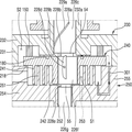
도 2 및 도 3은 도 1의 스크롤 압축기의 급유 구조의 일 예(1)를 설명하는 개략도들이다.Fig. 2 and Fig. 3 are schematic views for explaining an example (1) of the oil supply structure of the scroll compressor of Fig.
참고로, 도 2에는 원심 급유 구조에 따른 오일 흐름이 도시되어 있고, 도 3에는 차압 급유 구조에 따른 오일 흐름이 도시되어 있다. For reference, FIG. 2 shows the oil flow according to the centrifugal lubrication structure, and FIG. 3 shows the oil flow according to the differential pressure lubrication structure.
구체적으로, 저유 공간(도 1의 V4)에 저장되어 있던 오일은 회전축(226)의 오일 공급 유로(도 1의 226a)를 통해 상부로 안내(즉, 이동 또는 공급)될 수 있다. Specifically, the oil stored in the oil storage space (V4 in FIG. 1) can be guided upward (that is, moved or supplied) through the oil supply passage (226a in FIG. 1) of the rotary shaft 226.
또한, 도 2에 도시된 바와 같이, 오일 공급 유로(도 1의 226a)를 통해 상부로 안내된 오일은, 제1 오일 홀(228a)을 통해 토출되어 메인 베어링부(226c)의 외주면에 전체적으로 공급될 수 있다. 2, the oil guided upward through the oil supply passage (226a in Fig. 1) is discharged through the
또한 오일 공급 유로(도 1의 226a)를 통해 상부로 안내된 오일은, 제2 오일 홀(228b)을 통해 토출되어 선회 스크롤(240)의 상면(즉, 제3 경판부(도 1의 245)의 상면)에 공급될 수 있다. The oil guided upward through the oil supply passage 226a in FIG. 1 is discharged through the
또한 오일 공급 유로(도 1의 226a)를 통해 상부로 안내된 오일은, 제3 오일 홀(228d)을 통해 토출되어 편심부(226f)의 외주면에 전체적으로 공급될 수 있다. Further, the oil guided upward through the oil supply passage 226a (FIG. 1) may be discharged through the
또한 오일 공급 유로(도 1의 226a)를 통해 상부로 안내된 오일은, 제4 오일 홀(228e)을 통해 토출되어 서브 베어링부(226g)의 외주면 또는 선회 스크롤(240)과 고정 스크롤(250) 사이에 공급될 수 있다.The oil guided upward through the oil supply passage 226a is discharged through the
이와 같이, 저유 공간(V4)에 담긴 오일이 회전축(226)을 통해 상부로 안내되어 복수개의 오일 홀(228a, 228b, 228d, 228e)을 통해 베어링부, 즉, 베어링면에 원활하게 공급됨으로써 베어링부의 마모가 방지될 수 있다. Thus, the oil contained in the oil storage space V4 is guided upward through the rotation shaft 226 and smoothly supplied to the bearing portion, that is, the bearing surface through the plurality of
또한 복수개의 오일 홀(228a, 228b, 228d, 228e)을 통해 토출된 오일은 고정 스크롤(250)과 선회 스크롤(240) 사이에 유막을 형성하여 기밀 상태가 유지되도록 할 수 있다. Also, the oil discharged through the plurality of
그 뿐만 아니라 복수개의 오일 홀(228a, 228b, 228d, 228e)을 통해 토출된 오일은 마찰 부분에서 발생된 마찰열을 흡수하여 고온의 압축부(200)를 방열시킬 수도 있다. In addition, the oil discharged through the plurality of
한편, 오일 공급 유로(도 1의 226a)를 통해 상부로 안내된 고압의 오일은, 오일 홀(예를 들어, 제2 오일 홀(228b))을 통해 토출되어 선회 스크롤(240)의 상면에 공급될 수 있다. 또한 선회 스크롤(240)의 상면에 공급된 오일은 포켓 홈(180)을 통해 중간압실(S2)로 안내될 수 있다. On the other hand, the high-pressure oil guided upward through the oil supply passage 226a is discharged through the oil hole (for example, the
즉, 도 3에 도시된 바와 같이, 오일 공급 유로(도 1의 226a)를 통해 상부로 안내된 고압의 오일은, 오일 홀(예를 들어, 제2 오일 홀(228b))을 통해 토출되어 포켓 홈(180)으로 안내될 수 있다. 또한 포켓 홈(180)으로 안내된 오일은 선회 스크롤(240)의 선회 운동에 의해 중간압실(S2)로 공급될 수 있다.3, the high-pressure oil guided upward through the oil supply passage 226a (FIG. 1) is discharged through the oil hole (for example, the
참고로, 제2 오일 홀(228b) 뿐만 아니라 제1 오일 홀(228a) 또는 제3 오일 홀(228d)을 통해 토출된 오일이 포켓 홈(180)으로 공급될 수도 있다. The oil discharged through the
한편, 중간압실(S2)로 안내된 오일은 선회 스크롤(240)과 메인 프레임(230) 사이에 설치되는 올담링(150)과 고정 스크롤(250)의 스러스트면에 공급될 수 있다.The oil guided to the intermediate pressure chamber S2 may be supplied to the thrust surfaces of the
즉, 중간압실(S2) 내로 인입된 오일은 고정 스크롤(250)의 스러스트면과, 올담링(150)에 충분히 제공될 수 있다. In other words, the oil drawn into the intermediate pressure chamber S2 can be sufficiently provided to the thrust face of the fixed
이를 통해, 고정 스크롤(250)의 스러스트면 및 올담링(150)의 마모를 저감할 수 있다. As a result, the wear of the thrust face of the fixed
그 뿐만 아니라 중간압실(S2)로 안내된 오일은 고정 스크롤(250)에 구비된 차압 급유 유로(301)로 안내될 수 있다. In addition, the oil guided to the intermediate pressure chamber S2 can be guided to the differential pressure
구체적으로, 도 1의 스크롤 압축기의 고정 스크롤(250)에는 중간압실(즉, S2)로 안내된 오일을 압축실(S1)로 안내하기 위한 차압 급유 유로(301)가 더 구비될 수 있다. Specifically, the fixed
여기에서, 차압 급유 유로(301)는 제2 측벽부(255) 및 제2 경판부(254)를 관통하도록 형성될 수 있으나, 이에 한정되는 것은 아니다.Here, the differential
즉, 차압 급유 유로(301)는 제2 측벽부(255)만을 관통하도록 형성될 수도 있다. 이 경우, 제2 측벽부(255)와 제2 경판부(254)를 모두 관통하도록 형성될 때보다 차압 급유 유로(301) 길이가 짧아질 수 있다. That is, the differential pressure
또한, 차압 급유 유로(301)의 일단은 중간압실(S2)과 연통되고, 차압 급유 유로(301)의 타단은 압축실(S1)과 연통될 수 있다. One end of the differential pressure
이에 따라, 차압 급유 유로(301)로 안내된 오일은 압축실(S1)로 공급될 수 있는 것이다. Accordingly, the oil guided to the differential pressure
이와 같이, 저유 공간에 담긴 오일은 포켓 홈(180) 및 차압 급유 유로(301)를 통해 압축실(S1)에 원활하게 공급될 수 있다. Thus, the oil contained in the oil storage space can be smoothly supplied to the
또한 압축실(S1)에 오일이 원활하게 공급됨으로써, 선회 스크롤(240)과 고정 스크롤(250) 간 마찰에 따른 마모가 저감될 수 있고, 이를 통해, 압축 효율이 개선될 수 있다.Further, since oil is smoothly supplied to the compression chamber (S1), wear due to friction between the orbiting scroll (240) and the fixed scroll (250) can be reduced and the compression efficiency can be improved.
그 뿐만 아니라 압축실(S1)에 공급된 오일은 고정 스크롤(250)과 선회 스크롤(240) 사이에 유막을 형성하여 기밀 상태가 유지되도록 할 수 있다. In addition, the oil supplied to the compression chamber S1 may form an oil film between the
나아가 압축실(S1)에 공급된 오일은 고정 스크롤(250)과 선회 스크롤(240) 간 마찰시 발생된 마찰열을 흡수하여 방열시킬 수도 있다. Furthermore, the oil supplied to the compression chamber (S1) may absorb the frictional heat generated during the friction between the fixed scroll (250) and the orbiting scroll (240) to dissipate heat.
이하에서는, 도 4 및 도 5를 참조하여, 도 1의 스크롤 압축기의 급유 구조의 다른 예(2)를 설명하도록 한다.Hereinafter, another example (2) of the oil supply structure of the scroll compressor of Fig. 1 will be described with reference to Fig. 4 and Fig.
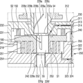
도 4 및 도 5는 도 1의 스크롤 압축기의 급유 구조의 다른 예를 설명하는 개략도들이다.Fig. 4 and Fig. 5 are schematic views for explaining another example of the oil supply structure of the scroll compressor of Fig.
참고로, 도 4에는 원심 급유 구조에 따른 오일 흐름이 도시되어 있고, 도 5에는 차압 급유 구조에 따른 오일 흐름이 도시되어 있다. For reference, FIG. 4 shows the oil flow according to the centrifugal lubrication structure, and FIG. 5 shows the oil flow according to the differential pressure lubrication structure.
다만, 도 4에 도시된 원심 급유 구조 및 포켓 홈(180)에 따른 오일 흐름은 도 2에 도시된 일 예와 동일한바, 이에 대한 설명은 생략하도록 한다. However, the oil flow according to the centrifugal lubrication structure and the
도 1의 스크롤 압축기의 메인 프레임(230)에는 오일 홀(예를 들어, 제2 오일 홀(228b))을 통해 토출된 오일을 제공받는 제1 차압 급유 유로(311)가 더 구비될 수 있다.The
참고로, 제2 오일 홀(228b) 뿐만 아니라 제1 오일 홀(228a) 또는 제3 오일 홀(228d)을 통해 토출된 오일이 제1 차압 급유 유로(311)로 공급될 수도 있다. The oil discharged through the
또한, 제1 차압 급유 유로(311)는 중간압실(S2)을 우회하도록 형성(즉, 제1 경판부(232) 및 제1 측벽부(231)를 관통하도록 형성)될 수 있다.The first pressure-reducing
이를 통해, 제1 차압 급유 유로(311)는, 일단이 고압 영역과 연결되어 오일을 제공받을 수 있고, 타단은 제2 차압 급유 유로(321)의 일단과 연결될 수 있다.Accordingly, the first pressure-reducing
여기에서, 고압 영역은 제1 소경부(54)와 제1 차압 급유 유로(311)의 일단 사이의 영역을 의미할 수 있다. Here, the high-pressure region may mean a region between the first small-
한편, 고정 스크롤(250)에는 제1 차압 급유 유로(311)로부터 제공받은 오일을 압축실(S1)로 안내하기 위한 제2 차압 급유 유로(321)가 더 구비될 수 있다. 제2 차압 급유 유로(321)는 제2 측벽부(255) 및 제2 경판부(254)를 관통하도록 형성될 수 있다.The fixed
이를 통해, 제2 차압 급유 유로(321)는, 일단이 제1 차압 급유 유로(311)의 타단과 연결될 수 있고, 타단은 압축실(S1)과 연결될 수 있다. Accordingly, one end of the second pressure-
그리고, 메인 프레임(230)에는 제1 경판부(232)의 측면에서 제1 차압 급유 유로(311)의 일부를 개방시키는 제1 개구부(314) 및 제1 개구부(314)를 밀봉하는 제1 결합 부재(313)가 더 구비될 수 있다.The
또한, 고정 스크롤(250)에는, 제2 경판부(254)의 하면에서 제2 차압 급유 유로(321)의 일부를 개방시키는 제2 개구부(324) 및 제2 개구부(324)를 밀봉하는 제2 결합 부재(323)가 더 구비될 수 있다.The fixed
여기에서, 제1 결합 부재(313) 및 제2 결합 부재(323)는 예를 들어, 볼트(체결 방식 적용), 봉(압입 방식 적용), 볼(압입 방식 적용) 중 어느 하나일 수 있으나, 이에 한정되는 것은 아니다. Here, the first engaging
또한 제1 개구부(314)는 제1 차압 급유 유로(311)의 내측으로 제1 감압핀(312)을 인입하는데 이용되고, 제2 개구부(324)는 제2 차압 급유 유로(321)의 내측으로 제2 감압핀(322)을 인입하는데 이용될 수 있다. The
한편, 제1 및 제2 차압 급유 유로(311, 321)에 각각 제1 및 제2 감압핀(312, 322)이 인입되면, 제1 및 제2 개구부(314, 324)에는 제1 및 제2 결합 부재(313, 323)가 각각 결합될 수 있다. On the other hand, when the first and second
즉, 제1 결합 부재(313) 및 제2 결합 부재(323)가 제1 개구부(314) 및 제2 개구부(324)에 각각 결합됨으로써 제1 차압 급유 유로(311)와 제2 차압 급유 유로(321) 내 압력이 유지될 수 있다. That is, the first engaging
또한, 제1 차압 급유 유로(311)의 내부에는 제1 감압핀(312)이 구비될 수 있고, 제2 차압 급유 유로(321)의 내부에는 제2 감압핀(322)이 구비될 수 있다.The first pressure reducing
여기에서, 제1 감압핀(312)의 직경은 제1 차압 급유 유로(311)의 직경보다 작고, 제2 감압핀(322)의 직경은 제2 차압 급유 유로(321)의 직경보다 작을 수 있다.The diameter of the first
이를 통해, 제1 감압핀(312)은 제1 차압 급유 유로(311) 내에 오일이 이동할 수 있는 좁은 유로를 형성함으로써, 제1 차압 급유 유로(311) 내의 압력 및 급유량 조절이 가능하다. Accordingly, the first
또한 제2 감압핀(322)은 제2 차압 급유 유로(321) 내에 오일이 이동할 수 있는 좁은 유로를 형성함으로써, 제2 차압 급유 유로(321) 내의 압력 및 급유량 조절이 가능하다.Further, the second
참고로, 제1 차압 급유 유로(311) 및 제2 차압 급유 유로(321) 중 어느 하나의 내부에만 감압핀이 구비될 수도 있다. 다만, 설명의 편의를 위해, 본 발명의 실시예에서는, 제1 차압 급유 유로(311) 및 제2 차압 급유 유로(321) 둘다의 내부에 감압핀이 구비되는 것을 예로 들어 설명하기로 한다. For reference, the pressure reducing pin may be provided only in the inside of the first pressure-reducing
이와 같이, 저유 공간에 담긴 오일은 제1 차압 급유 유로(311) 및 제2 차압 급유 유로(321)를 통해 압축실(S1)에 원활하게 공급될 수 있다.Thus, the oil contained in the oil storage space can be smoothly supplied to the compression chamber S1 through the first pressure-
또한 압축실(S1)에 오일이 원활하게 공급됨으로써, 전술한 일 예(1)에서의 효과(즉, 마모 저감, 기밀 상태 유지, 방열 등)와 동일한 효과를 다른 예(2)에서도 얻을 수 있다. In addition, since the oil is smoothly supplied to the compression chamber S1, the same effect as the effect of the above-described example (1) (i.e., reduction of wear, keeping of airtightness, .
이하에서는, 도 6 및 도 7을 참조하여, 도 1의 스크롤 압축기의 급유 구조의 또 다른 예(3)를 설명하도록 한다.Hereinafter, another example (3) of the oil supply structure of the scroll compressor of Fig. 1 will be described with reference to Fig. 6 and Fig.
도 6 및 도 7은 도 1의 스크롤 압축기의 급유 구조의 또 다른 예를 설명하는 개략도들이다.Figs. 6 and 7 are schematic views for explaining another example of the oil supply structure of the scroll compressor of Fig.
참고로, 도 6에는 원심 급유 구조에 따른 오일 흐름이 도시되어 있고, 도 7에는 차압 급유 구조에 따른 오일 흐름이 도시되어 있다. For reference, FIG. 6 shows the oil flow according to the centrifugal lubrication structure, and FIG. 7 shows the oil flow according to the differential pressure lubrication structure.
다만, 도 6에 도시된 원심 급유 구조 및 포켓 홈(180)에 따른 오일 흐름은 도 2에 도시된 일 예와 동일한바, 이에 대한 설명은 생략하도록 한다. However, the oil flow according to the centrifugal lubrication structure and the
도 1의 스크롤 압축기의 선회 스크롤(240)에는 오일 홀(예를 들어, 제2 오일 홀(228b))을 통해 토출된 오일을 제공받는 제1 차압 급유 유로(331)가 더 구비될 수 있다.The orbiting scroll 240 of the scroll compressor of FIG. 1 may further include a first differential pressure
참고로, 제2 오일 홀(228b) 뿐만 아니라 제1 오일 홀(228a) 또는 제3 오일 홀(228d)을 통해 토출된 오일이 제1 차압 급유 유로(331)로 공급될 수도 있다. The oil discharged through the
또한, 제1 차압 급유 유로(331)는 제3 경판부(245)를 관통하도록 형성될 수 있다. The first pressure-
이를 통해, 제1 차압 급유 유로(331)는, 일단이 고압 영역과 연결되어 오일을 제공받을 수 있고, 타단은 제2 차압 급유 유로(341)의 일단과 연결될 수 있다.Accordingly, one end of the first pressure-
여기에서, 고압 영역은 제1 소경부(54)와 제1 차압 급유 유로(331)의 일단 사이의 영역을 의미할 수 있다. Here, the high pressure region may mean a region between the first small-
한편, 고정 스크롤(250)에는 제1 차압 급유 유로(331)로부터 제공받은 오일을 압축실(S1)로 안내하기 위한 제2 차압 급유 유로(341)가 더 구비될 수 있다.The fixed
제2 차압 급유 유로(341)는 제2 측벽부(255) 및 제2 경판부(254)를 관통하도록 형성될 수 있다.The second pressure-
이를 통해, 제2 차압 급유 유로(341)는, 일단이 제1 차압 급유 유로(331)의 타단과 연결될 수 있고, 타단은 압축실(S1)과 연결될 수 있다.Accordingly, the second pressure-reducing
다만, 제1 차압 급유 유로(331)의 타단을 통해 토출된 오일은, 선회 스크롤(240)의 선회 운동으로 인해, 일부는 제2 차압 급유 유로(341)에 공급되고, 나머지 일부는 고정 스크롤(250)의 스러스트면에 공급될 수 있다. 또한, 선회 스크롤(240)에는 제3 경판부(245)의 측면에서 제1 차압 급유 유로(331)의 일부를 개방시키는 제1 개구부(334) 및 제1 개구부(334)를 밀봉하는 제1 결합 부재(333)가 더 구비될 수 있다.The oil discharged through the other end of the first pressure-sensing
그리고, 고정 스크롤(250)에는, 제2 경판부(254)의 하면에서 제2 차압 급유 유로(341)의 일부를 개방시키는 제2 개구부(344) 및 제2 개구부(344)를 밀봉하는 제2 결합 부재(343)가 더 구비될 수 있다.The fixed
여기에서, 제1 결합 부재(333) 및 제2 결합 부재(343)는 예를 들어, 볼트(체결 방식 적용), 봉(압입 방식 적용), 볼(압입 방식 적용) 중 어느 하나일 수 있으나, 이에 한정되는 것은 아니다. Here, the first engaging
또한 제1 개구부(334)는 제1 차압 급유 유로(331)의 내측으로 제1 감압핀(332)을 인입하는데 이용되고, 제2 개구부(344)는 제2 차압 급유 유로(341)의 내측으로 제2 감압핀(342)을 인입하는데 이용될 수 있다. The
한편, 제1 및 제2 차압 급유 유로(331, 341)에 각각 제1 및 제2 감압핀(332, 342)이 인입되면, 제1 및 제2 개구부(334, 344)에는 제1 및 제2 결합 부재(333, 343)가 각각 결합될 수 있다. On the other hand, when the first and second
즉, 제1 결합 부재(333) 및 제2 결합 부재(343)가 제1 개구부(334) 및 제2 개구부(344)에 각각 결합됨으로써 제1 차압 급유 유로(331)와 제2 차압 급유 유로(341) 내 압력이 유지될 수 있다. That is, the first engaging
또한, 제1 차압 급유 유로(331)의 내부에는 제1 감압핀(332)이 구비될 수 있고, 제2 차압 급유 유로(341)의 내부에는 제2 감압핀(342)이 구비될 수 있다.The first pressure reducing
여기에서, 제1 감압핀(332)의 직경은 제1 차압 급유 유로(331)의 직경보다 작고, 제2 감압핀(342)의 직경은 제2 차압 급유 유로(341)의 직경보다 작을 수 있다.The diameter of the first
이를 통해, 제1 감압핀(332)은 제1 차압 급유 유로(331) 내에 오일이 이동할 수 있는 좁은 유로를 형성함으로써, 제1 차압 급유 유로(331) 내의 압력 및 급유량 조절이 가능하다. Accordingly, the first
또한 제2 감압핀(342)은 제2 차압 급유 유로(341) 내에 오일이 이동할 수 있는 좁은 유로를 형성함으로써, 제2 차압 급유 유로(341) 내의 압력 및 급유량 조절이 가능하다.Further, the second
참고로, 제1 차압 급유 유로(331) 및 제2 차압 급유 유로(341) 중 어느 하나의 내부에만 감압핀이 구비될 수도 있다. 다만, 설명의 편의를 위해, 본 발명의 실시예에서는, 제1 차압 급유 유로(331) 및 제2 차압 급유 유로(341) 둘다의 내부에 감압핀이 구비되는 것을 예로 들어 설명하기로 한다. For reference, the pressure reducing pin may be provided only in the inside of the first pressure-reducing
이와 같이, 저유 공간에 담긴 오일은 제1 차압 급유 유로(331) 및 제2 차압 급유 유로(341)를 통해 압축실(S1)에 원활하게 공급될 수 있다.Thus, the oil contained in the oil-filled space can be smoothly supplied to the compression chamber S1 through the first pressure-
또한 압축실(S1)에 오일이 원활하게 공급됨으로써, 전술한 일 예(1)에서의 효과(즉, 마모 저감, 기밀 상태 유지, 방열 등)와 동일한 효과를 다른 예(2)에서도 얻을 수 있다. In addition, since the oil is smoothly supplied to the compression chamber S1, the same effect as the effect of the above-described example (1) (i.e., reduction of wear, keeping of airtightness, .
전술한 바와 같이, 본 발명에 따른 스크롤 압축기는 저유 공간(V4)에 담긴 오일을 회전축(226)을 토대로 한 원심 급유 구조를 통해 베어링부(특히, 베어링면)에 원활하게 공급함으로써 베어링부의 마모를 방지할 수 있다. 또한 베어링부의 마모를 방지함으로써 베어링부의 신뢰성도 확보할 수 있다.As described above, the scroll compressor according to the present invention smoothly supplies the oil contained in the oil storage space V4 to the bearing portion (particularly, the bearing surface) through the centrifugal oiling structure based on the rotation shaft 226, . Also, by preventing wear of the bearing portion, reliability of the bearing portion can be secured.
또한 본 발명에 따른 스크롤 압축기는 저유 공간(V4)에 담긴 오일을 다양한 차압 급유 구조를 통해 압축실(S1)에 원활하게 공급함으로써 선회 스크롤(240)과 고정 스크롤(250) 간 마찰에 따른 마모를 저감할 수 있고, 압축 효율을 개선할 수 있다. Further, the scroll compressor according to the present invention smoothly supplies oil contained in the oil storage space V4 to the compression chamber S1 through the various differential pressure lubricant structures, thereby improving wear due to friction between the orbiting
또한 본 발명에 따른 스크롤 압축기는 원심 급유 구조 및 차압 급유 구조를 통해 고정 스크롤(250)과 선회 스크롤(240) 사이에 유막을 형성하여 기밀 상태가 유지되도록 할 수 있고, 마찰 부분에서 발생된 마찰열을 흡수하여 고온의 압축부(200)를 방열시킬 수도 있다.In addition, the scroll compressor according to the present invention can form an oil film between the fixed scroll (250) and the orbiting scroll (240) through the centrifugal lubrication structure and the differential pressure lubrication structure to maintain the airtight state, And the high-temperature compression unit 200 may be discharged.
전술한 본 발명은, 본 발명이 속하는 기술 분야에서 통상의 지식을 가진 자에게 있어 본 발명의 기술적 사상을 벗어나지 않는 범위 내에서 여러 가지 치환, 변형 및 변경이 가능하므로 전술한 실시예 및 첨부된 도면에 의해 한정되는 것이 아니다.While the present invention has been described in connection with what is presently considered to be practical exemplary embodiments, it is to be understood that the invention is not limited to the disclosed embodiments, but, on the contrary, But the present invention is not limited thereto.
200: 압축부
210: 케이싱
220: 구동 모터
226: 회전축
230: 메인 프레임
240: 선회 스크롤
250: 고정 스크롤
200: compression section 210: casing
220: drive motor 226:
230: main frame 240: orbiting scroll
250: fixed scroll
Claims (21)
상기 케이싱의 내부 공간에 구비되는 구동 모터;
상기 구동 모터에 결합되고, 상기 케이싱의 상기 저유 공간에 담긴 오일을 상부로 안내하도록 오일 공급 유로가 구비되며, 상기 오일 공급 유로에서 외주면으로 관통된 오일 홀이 구비되는 회전축;
상기 구동 모터의 하부에 구비되는 메인 프레임;
상기 메인 프레임의 하부에 구비되는 고정 스크롤; 및
상기 메인 프레임과 상기 고정 스크롤 사이에 구비되며, 상기 고정 스크롤과 압축실을 형성하도록 상기 고정 스크롤에 맞물려 선회 운동하는 선회 스크롤을 포함하되,
상기 메인 프레임, 상기 고정스크롤 및 상기 선회스크롤 사이에는 중간압실이 형성되고,
상기 선회 스크롤의 상면에는 상기 오일 홀을 통해 토출된 오일을 상기 중간압실로 안내하기 위한 포켓 홈이 형성되고,
상기 고정 스크롤에는 상기 중간압실로 안내된 오일을 상기 압축실로 안내하기 위한 차압 급유 유로가 구비되는
스크롤 압축기.
A casing in which oil is stored in a lower oil storage space;
A driving motor provided in an inner space of the casing;
A rotation shaft coupled to the drive motor and having an oil supply passage for guiding the oil contained in the oil storage space of the casing to an upper portion and an oil hole penetrating the outer circumference of the oil supply passage;
A main frame provided at a lower portion of the driving motor;
A fixed scroll provided at a lower portion of the main frame; And
And an orbiting scroll provided between the main frame and the fixed scroll and pivotally engaged with the fixed scroll to form the fixed scroll and the compression chamber,
An intermediate pressure chamber is formed between the main frame, the fixed scroll, and the orbiting scroll,
A pocket groove for guiding the oil discharged through the oil hole to the intermediate pressure chamber is formed on the upper surface of the orbiting scroll,
The fixed scroll is provided with a differential pressure oil supply passage for guiding the oil guided to the intermediate pressure chamber to the compression chamber
Scroll compressor.
상기 회전축에는,
상기 메인 프레임에 삽입되어 반경방향으로 지지되도록 형성되는 메인 베어링부와,
상기 선회 스크롤에 삽입되어 편심지게 결합되는 편심부와,
상기 고정 스크롤에 삽입되어 반경방향으로 지지되도록 형성되는 서브 베어링부가 더 구비되는
스크롤 압축기.
The method according to claim 1,
In the rotation shaft,
A main bearing part inserted in the main frame and formed to be supported in a radial direction,
An eccentric portion inserted and eccentrically engaged with the orbiting scroll,
And a sub-bearing portion inserted into the fixed scroll and formed to be supported in a radial direction
Scroll compressor.
상기 오일 홀은,
상기 오일 공급 유로에서 상기 메인 베어링부의 외주면으로 관통되도록 형성된 제1 오일 홀과,
상기 메인 베어링부와 상기 편심부 사이에 형성된 제2 오일 홀과,
상기 오일 공급 유로에서 상기 편심부의 외주면으로 관통되도록 형성된 제3 오일 홀과,
상기 편심부와 상기 서브 베어링부 사이에 형성된 제4 오일 홀을 포함하는
스크롤 압축기.
3. The method of claim 2,
The oil hole
A first oil hole formed to pass from the oil supply passage to an outer peripheral surface of the main bearing portion,
A second oil hole formed between the main bearing portion and the eccentric portion,
A third oil hole formed in the oil supply passage so as to pass through the outer peripheral surface of the eccentric portion,
And a fourth oil hole formed between the eccentric portion and the sub bearing portion
Scroll compressor.
상기 오일 공급 유로를 통해 상부로 안내된 오일은,
상기 제1 오일 홀을 통해 토출되어 상기 메인 베어링부의 외주면에 공급되고,
상기 제2 오일 홀을 통해 토출되어 상기 선회 스크롤의 상면에 공급되고,
상기 제3 오일 홀을 통해 토출되어 상기 편심부의 외주면에 공급되고,
상기 제4 오일 홀을 통해 토출되어 상기 서브 베어링부의 외주면 또는 상기 선회 스크롤과 상기 고정 스크롤 사이에 공급되는
스크롤 압축기.
The method of claim 3,
And the oil guided upward through the oil supply passage,
A first oil hole formed in the outer circumferential surface of the main bearing portion,
The second oil hole, and is supplied to the upper surface of the orbiting scroll,
The third oil hole, and is supplied to the outer peripheral surface of the eccentric portion,
And is discharged through the fourth oil hole and supplied to the outer peripheral surface of the sub bearing portion or between the orbiting scroll and the fixed scroll
Scroll compressor.
상기 메인 베어링부의 외주면에는 상기 제1 오일 홀에 일단이 연결된 사선형 또는 나선형의 제1 오일 그루브가 형성되고,
상기 제1 오일 그루브는 상기 회전축의 회전 방향 또는 회전 반대 방향으로 기울어진
스크롤 압축기.
The method of claim 3,
A first oil groove having one end connected to the first oil hole and a fourth oil groove having a spiral or helical shape is formed on an outer circumferential surface of the main bearing portion,
Wherein the first oil groove is inclined in the rotational direction or the rotational direction of the rotational shaft
Scroll compressor.
상기 편심부의 외주면에는 상기 제3 오일 홀과 연결되어 상하 방향으로 연장되도록 제2 오일 그루브가 형성되는
스크롤 압축기.
The method of claim 3,
And a second oil groove is formed on an outer circumferential surface of the eccentric portion so as to be connected to the third oil hole and extend in the vertical direction
Scroll compressor.
상기 저유 공간에 저장된 오일을 펌핑하기 위해 상기 서브 베어링부의 하단에 결합된 오일피더를 더 포함하되,
상기 오일피더는,
상기 회전축의 상기 오일 공급 유로에 삽입되어 결합되는 오일 공급관과 상기 오일 공급관의 내부에 삽입되어 오일을 흡상하는 오일흡상부재를 포함하는
스크롤 압축기.
3. The method of claim 2,
Further comprising an oil feeder coupled to a lower end of the sub bearing portion for pumping oil stored in the oil reservoir space,
The oil feeder includes:
An oil supply pipe inserted and coupled to the oil supply passage of the rotary shaft and an oil intake member inserted into the oil supply pipe to absorb the oil,
Scroll compressor.
상기 저유 공간에 저장된 오일을 펌핑하기 위해 상기 서브 베어링부에 결합된 트로코이드 펌프를 더 포함하는
스크롤 압축기.
3. The method of claim 2,
Further comprising a trochoid pump coupled to the sub-bearing portion for pumping oil stored in the stocked space
Scroll compressor.
상기 고정 스크롤에는, 고정 스크롤 경판부와, 상기 고정 스크롤 경판부의 외주부에서 상부로 돌출되도록 형성된 고정 스크롤 측벽부와, 상기 고정 스크롤 경판부의 상면에서 돌출되는 고정랩이 구비되고,
상기 선회 스크롤에는, 상기 회전축이 삽입되어 편심지게 결합되도록 회전축 결합부가 구비되는 선회 스크롤 경판부와, 상기 선회 스크롤 경판부에서 돌출되고 상기 고정랩에 맞물려 상기 압축실을 형성하는 선회랩이 구비되는
스크롤 압축기.
The method according to claim 1,
The fixed scroll includes a fixed scroll end plate portion, a fixed scroll side wall portion formed to protrude upward from an outer periphery of the fixed scroll end plate portion, and a fixed lap protruding from an upper surface of the fixed scroll end plate portion,
The orbiting scroll includes an orbiting scroll hard plate portion having a rotary shaft engaging portion to be engaged with the rotary shaft eccentrically and a swirl wrap protruding from the orbiting scroll hard plate portion and engaged with the fixed lap to form the compression chamber
Scroll compressor.
상기 포켓 홈은 상기 선회 스크롤 경판부의 상면에 형성되고,
상기 차압 급유 유로는 상기 고정 스크롤 측벽부 및 상기 고정 스크롤 경판부를 관통하도록 형성되는
스크롤 압축기.
10. The method of claim 9,
Wherein the pocket groove is formed on an upper surface of the orbiting scroll hard plate portion,
Wherein the differential pressure oil supply passage is formed so as to pass through the fixed scroll side wall portion and the fixed scroll hard plate portion
Scroll compressor.
상기 중간압실로 안내된 오일은 상기 선회 스크롤과 상기 메인 프레임 사이에 설치되는 올담링 및 상기 고정 스크롤의 스러스트면에 공급되는
스크롤 압축기.
The method according to claim 1,
The oil guided to the intermediate pressure chamber is supplied to the thrust face of the fixed scroll and the oil seal provided between the orbiting scroll and the main frame
Scroll compressor.
상기 케이싱의 내부 공간에 구비되는 구동 모터;
상기 구동 모터에 결합되고, 상기 케이싱의 상기 저유 공간에 담긴 오일을 상부로 안내하도록 오일 공급 유로가 구비되며, 상기 오일 공급 유로에서 외주면으로 관통된 오일 홀이 구비되는 회전축;
상기 구동 모터의 하부에 구비되는 메인 프레임;
상기 메인 프레임의 하부에 구비되는 고정 스크롤; 및
상기 메인 프레임과 상기 고정 스크롤 사이에 구비되며, 상기 고정 스크롤과 압축실을 형성하도록 상기 고정 스크롤에 맞물려 선회 운동하는 선회 스크롤을 포함하되,
상기 메인 프레임에는 상기 오일 홀을 통해 토출된 오일을 제공받는 제1 차압 급유 유로가 구비되고,
상기 고정 스크롤에는 상기 제1 차압 급유 유로로부터 제공받은 오일을 상기 압축실로 안내하기 위한 제2 차압 급유 유로가 구비되는
스크롤 압축기.
A casing in which oil is stored in a lower oil storage space;
A driving motor provided in an inner space of the casing;
A rotation shaft coupled to the drive motor and having an oil supply passage for guiding the oil contained in the oil storage space of the casing to an upper portion and an oil hole penetrating the outer circumference of the oil supply passage;
A main frame provided at a lower portion of the driving motor;
A fixed scroll provided at a lower portion of the main frame; And
And an orbiting scroll provided between the main frame and the fixed scroll and pivotally engaged with the fixed scroll to form the fixed scroll and the compression chamber,
Wherein the main frame is provided with a first differential pressure supply passage for receiving oil discharged through the oil holes,
The fixed scroll includes a second differential pressure supply passage for guiding the oil supplied from the first differential pressure supply passage to the compression chamber
Scroll compressor.
상기 메인 프레임, 상기 고정스크롤 및 상기 선회스크롤 사이에는 중간압실이 형성되고,
상기 제1 차압 급유 유로는 상기 중간압실을 우회하도록 형성되는
스크롤 압축기.
13. The method of claim 12,
An intermediate pressure chamber is formed between the main frame, the fixed scroll, and the orbiting scroll,
The first pressure-reducing oil supply passage is formed so as to bypass the intermediate pressure chamber
Scroll compressor.
상기 메인 프레임에는, 프레임 경판부와, 상기 프레임 경판부의 중앙에 구비되고 상기 회전축이 관통하는 프레임 축수부와, 상기 프레임 경판부의 외주부에서 하부로 돌출되는 프레임 측벽부가 구비되고,
상기 고정 스크롤에는, 고정 스크롤 경판부와, 상기 고정 스크롤 경판부의 외주부에서 상부로 돌출되도록 형성된 고정 스크롤 측벽부와, 상기 고정 스크롤 경판부의 상면에서 돌출되는 고정랩이 구비되는
스크롤 압축기.
13. The method of claim 12,
The main frame includes a frame holding portion, a frame bearing portion provided at the center of the frame holding portion and through which the rotating shaft passes, and a frame side wall portion projecting downward from an outer peripheral portion of the frame holding portion,
The fixed scroll includes a fixed scroll end plate portion, a fixed scroll side wall portion formed to protrude upward from an outer peripheral portion of the fixed scroll end plate portion, and a fixed wrap protruding from the upper surface of the fixed scroll end plate portion
Scroll compressor.
상기 메인 프레임에는, 상기 프레임 경판부의 측면에서 상기 제1 차압 급유 유로의 일부를 개방시키는 제1 개구부 및 상기 제1 개구부를 밀봉하는 제1 결합 부재가 더 구비되고,
상기 고정 스크롤에는, 상기 고정 스크롤 경판부의 하면에서 상기 제2 차압 급유 유로의 일부를 개방시키는 제2 개구부 및 상기 제2 개구부를 밀봉하는 제2 결합 부재가 더 구비되고,
상기 제1 차압 급유 유로의 내부에는 제1 감압핀이 구비되고,
상기 제2 차압 급유 유로의 내부에는 제2 감압핀이 구비되는
스크롤 압축기.
15. The method of claim 14,
The main frame further includes a first opening portion for opening a part of the first pressure-supply fuel passage from the side of the frame longitudinal plate portion and a first engaging member for sealing the first opening portion,
The fixed scroll further includes a second opening portion for opening a part of the second pressure-supply oil passage from the lower surface of the fixed scroll end plate portion and a second engaging member for sealing the second opening portion,
Wherein the first pressure reducing oil passage is provided with a first pressure reducing pin,
The second pressure reducing oil passage is provided with a second pressure reducing pin
Scroll compressor.
상기 제1 감압핀의 직경은 상기 제1 차압 급유 유로의 직경보다 작고,
상기 제2 감압핀의 직경은 상기 제2 차압 급유 유로의 직경보다 작은
스크롤 압축기.
16. The method of claim 15,
The diameter of the first pressure reducing pin is smaller than the diameter of the first pressure-
The diameter of the second pressure reducing pin is smaller than the diameter of the second pressure-
Scroll compressor.
상기 선회 스크롤에는, 상기 회전축이 삽입되어 편심지게 결합되도록 회전축 결합부가 구비되는 선회 스크롤 경판부와, 상기 선회 스크롤 경판부에서 돌출되고 상기 고정랩에 맞물려 상기 압축실을 형성하는 선회랩이 구비되고,
상기 선회 스크롤 경판부의 상면에는 상기 오일 홀을 통해 토출된 오일을 상기 중간압실로 안내하기 위한 포켓 홈이 형성되는
스크롤 압축기.
14. The method of claim 13,
Wherein the orbiting scroll includes an orbiting scroll hard plate portion having a rotary shaft engaging portion to which the rotary shaft is inserted and eccentrically inserted and a orbiting wrap protruding from the orbiting scroll hard plate portion and engaged with the fixed lap to form the compression chamber,
And a pocket groove for guiding the oil discharged through the oil hole to the intermediate pressure chamber is formed on the upper surface of the orbiting scroll hard plate portion
Scroll compressor.
상기 케이싱의 내부 공간에 구비되는 구동 모터;
상기 구동 모터에 결합되고, 상기 케이싱의 상기 저유 공간에 담긴 오일을 상부로 안내하도록 오일 공급 유로가 구비되며, 상기 오일 공급 유로에서 외주면으로 관통된 오일 홀이 구비되는 회전축;
상기 구동 모터의 하부에 구비되는 메인 프레임;
상기 메인 프레임의 하부에 구비되는 고정 스크롤; 및
상기 메인 프레임과 상기 고정 스크롤 사이에 구비되며, 상기 고정 스크롤과 압축실을 형성하도록 상기 고정 스크롤에 맞물려 선회 운동하는 선회 스크롤을 포함하되,
상기 선회 스크롤에는 상기 오일 홀을 통해 토출된 오일을 제공받는 제1 차압 급유 유로가 구비되고,
상기 고정 스크롤에는 상기 제1 차압 급유 유로로부터 제공받은 오일을 상기 압축실로 안내하기 위한 제2 차압 급유 유로가 구비되는
스크롤 압축기.
A casing in which oil is stored in a lower oil storage space;
A driving motor provided in an inner space of the casing;
A rotary shaft coupled to the drive motor and having an oil supply passage for guiding the oil contained in the oil storage space of the casing to an upper portion and having an oil hole penetrating the outer circumference of the oil supply passage;
A main frame provided at a lower portion of the driving motor;
A fixed scroll provided at a lower portion of the main frame; And
And an orbiting scroll provided between the main frame and the fixed scroll and pivotally engaged with the fixed scroll to form the fixed scroll and the compression chamber,
Wherein the orbiting scroll is provided with a first differential pressure supply passage which receives oil discharged through the oil hole,
The fixed scroll includes a second differential pressure supply passage for guiding the oil supplied from the first differential pressure supply passage to the compression chamber
Scroll compressor.
상기 선회 스크롤에는, 상기 선회 스크롤에 구비된 선회 스크롤 경판부의 측면에서 상기 제1 차압 급유 유로의 일부를 개방시키는 제1 개구부와, 상기 제1 개구부를 밀봉하는 제1 결합 부재가 구비되고,
상기 고정 스크롤에는, 상기 고정 스크롤에 구비된 고정 스크롤 경판부의 하면에서 상기 제2 차압 급유 유로의 일부를 개방시키는 제2 개구부와, 상기 제2 개구부를 밀봉하는 제2 결합 부재가 구비되고,
상기 제1 차압 급유 유로의 내부에는 제1 감압핀이 구비되고,
상기 제2 차압 급유 유로의 내부에는 제2 감압핀이 구비되는
스크롤 압축기.
19. The method of claim 18,
Wherein the orbiting scroll is provided with a first opening portion for opening a part of the first pressure-supply oil supply passage from the side of the orbiting scroll hard plate portion provided in the orbiting scroll and a first engaging member for sealing the first opening portion,
The fixed scroll is provided with a second opening portion for opening a part of the second pressure-supply oil supply pathway from the lower surface of the fixed scroll hard plate portion provided in the fixed scroll, and a second engaging member for sealing the second opening portion,
Wherein the first pressure reducing oil passage is provided with a first pressure reducing pin,
The second pressure reducing oil passage is provided with a second pressure reducing pin
Scroll compressor.
상기 메인 프레임, 상기 고정스크롤 및 상기 선회스크롤 사이에는 중간압실이 형성되고,
상기 선회 스크롤 경판부의 상면에는 상기 오일 홀을 통해 토출된 오일을 상기 중간압실로 안내하기 위한 포켓 홈이 형성되는
스크롤 압축기.
20. The method of claim 19,
An intermediate pressure chamber is formed between the main frame, the fixed scroll, and the orbiting scroll,
And a pocket groove for guiding the oil discharged through the oil hole to the intermediate pressure chamber is formed on the upper surface of the orbiting scroll hard plate portion
Scroll compressor.
상기 케이싱의 내부 공간에 구비되는 구동 모터;
상기 구동 모터에 결합되고, 상기 케이싱의 상기 저유 공간에 담긴 오일을 상기 구동 모터 측으로 안내하도록 오일 공급 유로가 구비되며, 상기 오일 공급 유로에서 외주면으로 관통된 오일 홀이 구비되는 회전축;
상기 구동 모터의 일측에 구비되는 메인 프레임;
상기 메인 프레임의 일측에 구비되는 고정 스크롤; 및
상기 메인 프레임과 상기 고정 스크롤 사이에 구비되며, 상기 고정 스크롤과 압축실을 형성하도록 상기 고정 스크롤에 맞물려 선회 운동하는 선회 스크롤을 포함하되,
상기 메인 프레임, 상기 고정스크롤 및 상기 선회스크롤 사이에는 중간압실이 형성되고,
상기 선회 스크롤의 일면에는 상기 오일 홀을 통해 토출된 오일을 상기 중간압실로 안내하기 위한 포켓 홈이 형성되고,
상기 고정 스크롤에는 상기 중간압실로 안내된 오일을 상기 압축실로 안내하기 위한 차압 급유 유로가 구비되는
스크롤 압축기.
A casing in which oil is stored in an oil storage space inside;
A driving motor provided in an inner space of the casing;
A rotary shaft coupled to the drive motor and having an oil supply passage for guiding the oil contained in the oil storage space of the casing to the drive motor side and an oil hole penetrating the outer circumference of the oil supply passage;
A main frame provided on one side of the driving motor;
A fixed scroll provided on one side of the main frame; And
And an orbiting scroll provided between the main frame and the fixed scroll and pivotally engaged with the fixed scroll to form the fixed scroll and the compression chamber,
An intermediate pressure chamber is formed between the main frame, the fixed scroll, and the orbiting scroll,
A pocket groove for guiding the oil discharged through the oil hole to the intermediate pressure chamber is formed on one surface of the orbiting scroll,
The fixed scroll is provided with a differential pressure oil supply passage for guiding the oil guided to the intermediate pressure chamber to the compression chamber
Scroll compressor.
Priority Applications (4)
| Application Number | Priority Date | Filing Date | Title |
|---|---|---|---|
| KR1020170075041A KR20180136282A (en) | 2017-06-14 | 2017-06-14 | Compressor having centrifugation and differential pressure structure for oil supplying |
| US15/830,135 US10781817B2 (en) | 2017-06-14 | 2017-12-04 | Compressor having centrifugation and differential pressure structure for oil supplying |
| EP17205582.4A EP3415761B1 (en) | 2017-06-14 | 2017-12-06 | Compressor having centrifugation and differential pressure structure for oil supplying |
| US16/692,112 US11248608B2 (en) | 2017-06-14 | 2019-11-22 | Compressor having centrifugation and differential pressure structure for oil supplying |
Applications Claiming Priority (1)
| Application Number | Priority Date | Filing Date | Title |
|---|---|---|---|
| KR1020170075041A KR20180136282A (en) | 2017-06-14 | 2017-06-14 | Compressor having centrifugation and differential pressure structure for oil supplying |
Publications (1)
| Publication Number | Publication Date |
|---|---|
| KR20180136282A true KR20180136282A (en) | 2018-12-24 |
Family
ID=60582495
Family Applications (1)
| Application Number | Title | Priority Date | Filing Date |
|---|---|---|---|
| KR1020170075041A Ceased KR20180136282A (en) | 2017-06-14 | 2017-06-14 | Compressor having centrifugation and differential pressure structure for oil supplying |
Country Status (3)
| Country | Link |
|---|---|
| US (2) | US10781817B2 (en) |
| EP (1) | EP3415761B1 (en) |
| KR (1) | KR20180136282A (en) |
Cited By (8)
| Publication number | Priority date | Publication date | Assignee | Title |
|---|---|---|---|---|
| KR20200099335A (en) * | 2019-02-14 | 2020-08-24 | 엘지전자 주식회사 | A compressor |
| KR20200116690A (en) * | 2019-04-02 | 2020-10-13 | 엘지전자 주식회사 | A compressor |
| KR20210008128A (en) * | 2019-04-02 | 2021-01-20 | 엘지전자 주식회사 | A compressor |
| WO2021215674A1 (en) * | 2020-04-21 | 2021-10-28 | 엘지전자 주식회사 | Compressor |
| KR20210130904A (en) * | 2020-04-22 | 2021-11-02 | 엘지전자 주식회사 | A compressor |
| KR20210150113A (en) * | 2020-06-03 | 2021-12-10 | 엘지전자 주식회사 | Compressor |
| US11635077B2 (en) | 2019-04-02 | 2023-04-25 | Lg Electronics Inc. | Scroll compressor having function of regulating oil supply path |
| WO2025198070A1 (en) * | 2024-03-21 | 2025-09-25 | 엘지전자 주식회사 | Scroll compressor |
Families Citing this family (2)
| Publication number | Priority date | Publication date | Assignee | Title |
|---|---|---|---|---|
| KR102448868B1 (en) * | 2020-04-20 | 2022-09-30 | 엘지전자 주식회사 | compressor |
| KR102673753B1 (en) | 2022-05-30 | 2024-06-11 | 엘지전자 주식회사 | Scroll compressor |
Family Cites Families (43)
| Publication number | Priority date | Publication date | Assignee | Title |
|---|---|---|---|---|
| JPS6030495A (en) | 1983-07-29 | 1985-02-16 | Hitachi Ltd | Lubricating mechanism of rotary compressor |
| US4596520A (en) | 1983-12-14 | 1986-06-24 | Hitachi, Ltd. | Hermetic scroll compressor with pressure differential control means for a back-pressure chamber |
| JPH0733829B2 (en) | 1986-02-03 | 1995-04-12 | 松下電器産業株式会社 | Scroll compressor |
| KR910001824B1 (en) | 1987-08-10 | 1991-03-26 | 가부시기가이샤 히다찌세이사꾸쇼 | Oil feeding system for scroll compressor |
| US4768936A (en) | 1987-11-27 | 1988-09-06 | Carrier Corporation | Scroll compressor with oil pickup tube in oil sump |
| JPH0778388B2 (en) | 1989-12-29 | 1995-08-23 | 松下電器産業株式会社 | Gas compressor |
| JP3245922B2 (en) | 1992-01-30 | 2002-01-15 | 松下電器産業株式会社 | Stationary vacuum cleaner |
| JPH0754784A (en) | 1993-08-09 | 1995-02-28 | Hitachi Ltd | Axial penetration scroll compressor |
| JPH07259757A (en) | 1994-03-24 | 1995-10-09 | Sanyo Electric Co Ltd | Rotary type scroll compressor |
| AU4645196A (en) | 1994-12-23 | 1996-07-19 | Bristol Compressors, Inc. | Scroll compressor having bearing structure in the orbiting scroll to eliminate tipping forces |
| WO1997017545A1 (en) | 1995-11-06 | 1997-05-15 | Bitzer Kühlmaschinenbau Gmbh & Co. Kg | Helical compressor |
| JP3045961B2 (en) * | 1996-06-14 | 2000-05-29 | 松下電器産業株式会社 | Scroll gas compression |
| JP2778585B2 (en) | 1996-06-14 | 1998-07-23 | 松下電器産業株式会社 | Scroll gas compressor |
| JP3635794B2 (en) | 1996-07-22 | 2005-04-06 | 松下電器産業株式会社 | Scroll gas compressor |
| JP3774964B2 (en) | 1996-12-10 | 2006-05-17 | 株式会社日立製作所 | Scroll compressor |
| US6171086B1 (en) | 1997-11-03 | 2001-01-09 | Carrier Corporation | Scroll compressor with pressure equalization groove |
| JP3731069B2 (en) | 2002-07-29 | 2006-01-05 | ダイキン工業株式会社 | Compressor |
| KR100811361B1 (en) | 2004-12-22 | 2008-03-07 | 미쓰비시덴키 가부시키가이샤 | Scroll compressor |
| JP2009036069A (en) | 2007-08-01 | 2009-02-19 | Sanden Corp | Scroll type fluid machine |
| US7997883B2 (en) | 2007-10-12 | 2011-08-16 | Emerson Climate Technologies, Inc. | Scroll compressor with scroll deflection compensation |
| KR101487822B1 (en) | 2008-11-14 | 2015-01-29 | 엘지전자 주식회사 | Hermetic compressor and refrigeration equipment using it |
| JP5201113B2 (en) | 2008-12-03 | 2013-06-05 | 株式会社豊田自動織機 | Scroll compressor |
| JP4941480B2 (en) | 2009-02-03 | 2012-05-30 | パナソニック株式会社 | Scroll compressor |
| JP5199951B2 (en) | 2009-06-01 | 2013-05-15 | 日立アプライアンス株式会社 | Scroll compressor |
| JP2011038480A (en) | 2009-08-12 | 2011-02-24 | Sanden Corp | Scroll fluid machine |
| KR101587171B1 (en) | 2009-12-08 | 2016-01-21 | 엘지전자 주식회사 | Scroll compressor and refrigeration equipment using it |
| JP5562263B2 (en) | 2011-01-11 | 2014-07-30 | アネスト岩田株式会社 | Scroll fluid machinery |
| KR101059880B1 (en) | 2011-03-09 | 2011-08-29 | 엘지전자 주식회사 | Scroll compressor |
| JP5152359B2 (en) | 2011-03-23 | 2013-02-27 | ダイキン工業株式会社 | Scroll compressor |
| KR101810461B1 (en) | 2011-03-24 | 2017-12-19 | 엘지전자 주식회사 | Scroll compressor |
| CN102817840B (en) | 2011-06-07 | 2014-08-27 | 思科涡旋科技(杭州)有限公司 | Scroll-type volume displacement device with orbiting thrust bearing |
| KR101480472B1 (en) | 2011-09-28 | 2015-01-09 | 엘지전자 주식회사 | Scroll compressor |
| JP6022375B2 (en) | 2013-02-21 | 2016-11-09 | ジョンソンコントロールズ ヒタチ エア コンディショニング テクノロジー(ホンコン)リミテッド | Scroll compressor |
| FR3006387B1 (en) | 2013-05-31 | 2016-02-19 | Danfoss Commercial Compressors | SPIRAL COMPRESSOR |
| WO2014198215A1 (en) | 2013-06-14 | 2014-12-18 | 艾默生环境优化技术(苏州)有限公司 | Scroll compressor, fixed scroll member and orbiting scroll member |
| JP5765379B2 (en) * | 2013-08-10 | 2015-08-19 | ダイキン工業株式会社 | Scroll compressor |
| WO2015085823A1 (en) | 2013-12-12 | 2015-06-18 | 艾默生环境优化技术(苏州)有限公司 | Scroll compressor |
| KR102234708B1 (en) | 2014-08-06 | 2021-04-01 | 엘지전자 주식회사 | compressor |
| KR102226457B1 (en) | 2014-08-08 | 2021-03-11 | 엘지전자 주식회사 | compressor |
| KR102241201B1 (en) | 2014-08-13 | 2021-04-16 | 엘지전자 주식회사 | Scroll compressor |
| KR102245438B1 (en) * | 2014-08-19 | 2021-04-29 | 엘지전자 주식회사 | compressor |
| KR101729579B1 (en) | 2015-05-18 | 2017-04-24 | 엘지전자 주식회사 | Compressor |
| KR102303545B1 (en) * | 2017-05-12 | 2021-09-17 | 엘지전자 주식회사 | Scroll compressor |
-
2017
- 2017-06-14 KR KR1020170075041A patent/KR20180136282A/en not_active Ceased
- 2017-12-04 US US15/830,135 patent/US10781817B2/en active Active
- 2017-12-06 EP EP17205582.4A patent/EP3415761B1/en active Active
-
2019
- 2019-11-22 US US16/692,112 patent/US11248608B2/en active Active
Cited By (12)
| Publication number | Priority date | Publication date | Assignee | Title |
|---|---|---|---|---|
| KR20200099335A (en) * | 2019-02-14 | 2020-08-24 | 엘지전자 주식회사 | A compressor |
| US11353026B2 (en) | 2019-02-14 | 2022-06-07 | Lg Electronics Inc. | Compressor having decompressing structure |
| KR20200116690A (en) * | 2019-04-02 | 2020-10-13 | 엘지전자 주식회사 | A compressor |
| KR20210008128A (en) * | 2019-04-02 | 2021-01-20 | 엘지전자 주식회사 | A compressor |
| US11401933B2 (en) | 2019-04-02 | 2022-08-02 | Lg Electronics Inc. | Scroll-type compressor |
| US11635077B2 (en) | 2019-04-02 | 2023-04-25 | Lg Electronics Inc. | Scroll compressor having function of regulating oil supply path |
| WO2021215674A1 (en) * | 2020-04-21 | 2021-10-28 | 엘지전자 주식회사 | Compressor |
| KR20210129922A (en) * | 2020-04-21 | 2021-10-29 | 엘지전자 주식회사 | A compressor |
| US12331742B2 (en) | 2020-04-21 | 2025-06-17 | Lg Electronics Inc. | Compressor |
| KR20210130904A (en) * | 2020-04-22 | 2021-11-02 | 엘지전자 주식회사 | A compressor |
| KR20210150113A (en) * | 2020-06-03 | 2021-12-10 | 엘지전자 주식회사 | Compressor |
| WO2025198070A1 (en) * | 2024-03-21 | 2025-09-25 | 엘지전자 주식회사 | Scroll compressor |
Also Published As
| Publication number | Publication date |
|---|---|
| EP3415761B1 (en) | 2025-05-07 |
| US20180363655A1 (en) | 2018-12-20 |
| US20200088199A1 (en) | 2020-03-19 |
| US11248608B2 (en) | 2022-02-15 |
| EP3415761A1 (en) | 2018-12-19 |
| US10781817B2 (en) | 2020-09-22 |
Similar Documents
| Publication | Publication Date | Title |
|---|---|---|
| KR20180136282A (en) | Compressor having centrifugation and differential pressure structure for oil supplying | |
| KR101974272B1 (en) | Compressor having merged flow path structure | |
| US9617996B2 (en) | Compressor | |
| US8043079B2 (en) | Hermetic compressor and refrigeration cycle device having the same | |
| CN114909291B (en) | Oil return structure of compressor, compressor and air conditioner | |
| KR20190011115A (en) | Compressor having centrifugation structure for supplying oil | |
| KR101964962B1 (en) | Compressor having a structure for preventing reverse flow of refrigerant | |
| EP3418572B1 (en) | Compressor having lubrication structure for thrust surface | |
| EP3705723B1 (en) | Scroll compressor | |
| EP3705724B1 (en) | Scroll compressor having noise reduction structure | |
| KR20190001070A (en) | Compressor having enhanced structure for discharging refrigerant | |
| US11713752B2 (en) | Scroll compressor of lower compression type enabling active oil supply | |
| JP2004036583A (en) | Compressor | |
| KR101300258B1 (en) | Scroll compressor | |
| KR102548470B1 (en) | Compressor having oldham's ring | |
| KR20190000176A (en) | Compressor having spiral oil groove structure | |
| KR20190004200A (en) | Compressor having enhanced structure for preventing refrigerant leakage | |
| KR101988719B1 (en) | Compressor having oil groove placed on bottom surface of eccentric part | |
| KR20190001069A (en) | Compressor having oldham's ring | |
| KR20190004985A (en) | Compressor having structure of gradually changing oil path area |
Legal Events
| Date | Code | Title | Description |
|---|---|---|---|
| PA0109 | Patent application |
Patent event code: PA01091R01D Comment text: Patent Application Patent event date: 20170614 |
|
| PA0201 | Request for examination | ||
| PE0902 | Notice of grounds for rejection |
Comment text: Notification of reason for refusal Patent event date: 20180716 Patent event code: PE09021S01D |
|
| AMND | Amendment | ||
| E601 | Decision to refuse application | ||
| PE0601 | Decision on rejection of patent |
Patent event date: 20181129 Comment text: Decision to Refuse Application Patent event code: PE06012S01D Patent event date: 20180716 Comment text: Notification of reason for refusal Patent event code: PE06011S01I |
|
| AMND | Amendment | ||
| PX0901 | Re-examination |
Patent event code: PX09011S01I Patent event date: 20181129 Comment text: Decision to Refuse Application Patent event code: PX09012R01I Patent event date: 20180808 Comment text: Amendment to Specification, etc. |
|
| PG1501 | Laying open of application | ||
| PX0601 | Decision of rejection after re-examination |
Comment text: Decision to Refuse Application Patent event code: PX06014S01D Patent event date: 20181226 Comment text: Amendment to Specification, etc. Patent event code: PX06012R01I Patent event date: 20181219 Comment text: Decision to Refuse Application Patent event code: PX06011S01I Patent event date: 20181129 Comment text: Amendment to Specification, etc. Patent event code: PX06012R01I Patent event date: 20180808 Comment text: Notification of reason for refusal Patent event code: PX06013S01I Patent event date: 20180716 |