KR20180131974A - Spring-loaded tip assembly to support simulated shielded metal arc welding - Google Patents
Spring-loaded tip assembly to support simulated shielded metal arc welding Download PDFInfo
- Publication number
- KR20180131974A KR20180131974A KR1020180061140A KR20180061140A KR20180131974A KR 20180131974 A KR20180131974 A KR 20180131974A KR 1020180061140 A KR1020180061140 A KR 1020180061140A KR 20180061140 A KR20180061140 A KR 20180061140A KR 20180131974 A KR20180131974 A KR 20180131974A
- Authority
- KR
- South Korea
- Prior art keywords
- compression spring
- electrode tip
- housing
- simulated
- locking
- Prior art date
Links
Images


Classifications
-
- G—PHYSICS
- G09—EDUCATION; CRYPTOGRAPHY; DISPLAY; ADVERTISING; SEALS
- G09B—EDUCATIONAL OR DEMONSTRATION APPLIANCES; APPLIANCES FOR TEACHING, OR COMMUNICATING WITH, THE BLIND, DEAF OR MUTE; MODELS; PLANETARIA; GLOBES; MAPS; DIAGRAMS
- G09B25/00—Models for purposes not provided for in G09B23/00, e.g. full-sized devices for demonstration purposes
- G09B25/02—Models for purposes not provided for in G09B23/00, e.g. full-sized devices for demonstration purposes of industrial processes; of machinery
-
- B—PERFORMING OPERATIONS; TRANSPORTING
- B23—MACHINE TOOLS; METAL-WORKING NOT OTHERWISE PROVIDED FOR
- B23K—SOLDERING OR UNSOLDERING; WELDING; CLADDING OR PLATING BY SOLDERING OR WELDING; CUTTING BY APPLYING HEAT LOCALLY, e.g. FLAME CUTTING; WORKING BY LASER BEAM
- B23K9/00—Arc welding or cutting
- B23K9/16—Arc welding or cutting making use of shielding gas
- B23K9/173—Arc welding or cutting making use of shielding gas and of a consumable electrode
-
- G—PHYSICS
- G09—EDUCATION; CRYPTOGRAPHY; DISPLAY; ADVERTISING; SEALS
- G09B—EDUCATIONAL OR DEMONSTRATION APPLIANCES; APPLIANCES FOR TEACHING, OR COMMUNICATING WITH, THE BLIND, DEAF OR MUTE; MODELS; PLANETARIA; GLOBES; MAPS; DIAGRAMS
- G09B19/00—Teaching not covered by other main groups of this subclass
- G09B19/24—Use of tools
-
- B—PERFORMING OPERATIONS; TRANSPORTING
- B23—MACHINE TOOLS; METAL-WORKING NOT OTHERWISE PROVIDED FOR
- B23K—SOLDERING OR UNSOLDERING; WELDING; CLADDING OR PLATING BY SOLDERING OR WELDING; CUTTING BY APPLYING HEAT LOCALLY, e.g. FLAME CUTTING; WORKING BY LASER BEAM
- B23K9/00—Arc welding or cutting
- B23K9/18—Submerged-arc welding
-
- B—PERFORMING OPERATIONS; TRANSPORTING
- B23—MACHINE TOOLS; METAL-WORKING NOT OTHERWISE PROVIDED FOR
- B23K—SOLDERING OR UNSOLDERING; WELDING; CLADDING OR PLATING BY SOLDERING OR WELDING; CUTTING BY APPLYING HEAT LOCALLY, e.g. FLAME CUTTING; WORKING BY LASER BEAM
- B23K9/00—Arc welding or cutting
- B23K9/24—Features related to electrodes
- B23K9/26—Accessories for electrodes, e.g. ignition tips
-
- B—PERFORMING OPERATIONS; TRANSPORTING
- B23—MACHINE TOOLS; METAL-WORKING NOT OTHERWISE PROVIDED FOR
- B23K—SOLDERING OR UNSOLDERING; WELDING; CLADDING OR PLATING BY SOLDERING OR WELDING; CUTTING BY APPLYING HEAT LOCALLY, e.g. FLAME CUTTING; WORKING BY LASER BEAM
- B23K9/00—Arc welding or cutting
- B23K9/24—Features related to electrodes
- B23K9/28—Supporting devices for electrodes
- B23K9/29—Supporting devices adapted for making use of shielding means
- B23K9/291—Supporting devices adapted for making use of shielding means the shielding means being a gas
-
- B—PERFORMING OPERATIONS; TRANSPORTING
- B23—MACHINE TOOLS; METAL-WORKING NOT OTHERWISE PROVIDED FOR
- B23K—SOLDERING OR UNSOLDERING; WELDING; CLADDING OR PLATING BY SOLDERING OR WELDING; CUTTING BY APPLYING HEAT LOCALLY, e.g. FLAME CUTTING; WORKING BY LASER BEAM
- B23K9/00—Arc welding or cutting
- B23K9/32—Accessories
-
- G—PHYSICS
- G09—EDUCATION; CRYPTOGRAPHY; DISPLAY; ADVERTISING; SEALS
- G09B—EDUCATIONAL OR DEMONSTRATION APPLIANCES; APPLIANCES FOR TEACHING, OR COMMUNICATING WITH, THE BLIND, DEAF OR MUTE; MODELS; PLANETARIA; GLOBES; MAPS; DIAGRAMS
- G09B19/00—Teaching not covered by other main groups of this subclass
- G09B19/003—Repetitive work cycles; Sequence of movements
-
- G—PHYSICS
- G09—EDUCATION; CRYPTOGRAPHY; DISPLAY; ADVERTISING; SEALS
- G09B—EDUCATIONAL OR DEMONSTRATION APPLIANCES; APPLIANCES FOR TEACHING, OR COMMUNICATING WITH, THE BLIND, DEAF OR MUTE; MODELS; PLANETARIA; GLOBES; MAPS; DIAGRAMS
- G09B9/00—Simulators for teaching or training purposes
Landscapes
- Engineering & Computer Science (AREA)
- Physics & Mathematics (AREA)
- Business, Economics & Management (AREA)
- Plasma & Fusion (AREA)
- Mechanical Engineering (AREA)
- Theoretical Computer Science (AREA)
- Educational Administration (AREA)
- Educational Technology (AREA)
- General Physics & Mathematics (AREA)
- Entrepreneurship & Innovation (AREA)
- Instructional Devices (AREA)
- Arc Welding In General (AREA)
- Arc Welding Control (AREA)
- Resistance Welding (AREA)
Abstract
Description
관련 출원의 상호 참조/참조에 의한 통합Cross reference / reference by reference of related application
본 미국 특허출원은 2017년 6월 1일에 출원된 미국 가출원 일련번호 제62/513,584호의 이점 및 우선권을 주장하고, 그 전체가 본원에 참조로 포함된다. 2009년 7월 10일에 출원되고 2014년 12월 23일에 허여된 "가상 현실 파이프 용접 시뮬레이터(Virtual Reality Pipe Welding Simulator)"라는 명칭의 미국 특허 제8,915,740호는 그 전체가 본원에 참조로 포함된다.This U.S. patent application claims priority and priority to U.S. Provisional Application Serial No. 62 / 513,584, filed June 1, 2017, the entirety of which is incorporated herein by reference. U.S. Patent No. 8,915,740, entitled " Virtual Reality Pipe Welding Simulator, " filed July 10, 2009 and issued on December 23, 2014, is incorporated herein by reference in its entirety .
본 발명의 구현예들은 시뮬레이션 용접과 연관된 시스템, 장치, 및 방법에 관한 것이다. 보다 구체적으로, 본 발명의 구현예들은 스프링-장착식 팁 조립체를 통해 피복 금속 아크 용접(SMAW) 작업의 시뮬레이션을 지원하는 시스템, 장치, 및 방법에 관한 것이다.Embodiments of the present invention are directed to systems, apparatus, and methods associated with simulated welding. More particularly, embodiments of the present invention are directed to a system, apparatus, and method for supporting simulation of a Coated Metal Arc Welding (SMAW) operation through a spring-mounted tip assembly.
특정 용접 조인트(예를 들어, SMAW 파이프 용접)에서, 용접 공정은 사용자가 사용되는 전극을 통해 공작물의 용접 조인트를 느낄 것을 요구한다. 적절한 아크 거리를 찾기 위해 용접 조인트에 인가되어야 하는 이상적인 압력이 존재한다. 현재 전문 용접공은 적절한 아크 길이 및 용접 용착율을 얻기 위해 제1 접점 너머의 조인트에 전극을 공급한다. 용접생들을 훈련하기 위해 SMAW 파이프 용접 공정을 시뮬레이션하는 것은 어려울 수 있다. 오늘날의 시뮬레이션/가상 용접 훈련 시스템에 의하면, 모의 SMAW 공구의 일부로 제공되는 인공 전극 팁은 강성인 경향이 있다. 이는 SMAW 작업의 비현실적인 시뮬레이션을 초래한다. 예를 들어, 전극 미끄러짐이 용접 쿠폰에서 일어날 수 있고, 압력-기반 용접 기술이 부재하며, 적절한 배치가 부족하다. SMAW 파이프 용접 공정을 보다 현실적으로 시뮬레이션할 방법이 필요하다.In certain weld joints (e.g., SMAW pipe welding), the welding process requires the user to feel the weld joint of the workpiece through the electrode being used. There is an ideal pressure that must be applied to the weld joint to find the proper arc distance. At present, a professional welder feeds electrodes to the joint beyond the first contact to obtain an appropriate arc length and welding deposition rate. Simulating a SMAW pipe welding process to train welders may be difficult. According to today's simulation / virtual weld training system, the artificial electrode tips provided as part of the simulated SMAW tool tend to be stiff. This results in an unrealistic simulation of the SMAW operation. For example, electrode slippage can occur in a weld coupon, there is no pressure-based welding technique, and adequate placement is lacking. A more realistic way to simulate the SMAW pipe welding process is needed.
본 발명의 구현예들은 용접생들을 훈련하기 위해 피복 금속 아크 용접(SMAW) 작업의 시뮬레이션을 지원하는 스프링-장착식 팁 조립체를 포함한다. 스프링-장착식 팁 조립체는, 용접 쿠폰에서 미끄러짐을 완화하며 용접생에게 압력-기반 촉각 피드백을 제공하는 세장형 모의 전극 팁을 포함한다.Embodiments of the present invention include a spring-mounted tip assembly that supports simulation of a Closed Metal Arc Weld (SMAW) operation to train welders. The spring-mountable tip assembly includes a elongated simulated electrode tip that mitigates slippage in the weld coupon and provides pressure-based tactile feedback to the welder.
일 구현예는 피복 금속 아크 용접(SMAW) 작업의 시뮬레이션을 지원하는 팁 조립체를 포함한다. 팁 조립체는 근위 단부, 원위 단부, 및 근위 단부 인근의 잠금 슬리브를 구비한 세장형 모의 전극 팁을 포함한다. 팁 조립체는 또한 제1 단부 및 제2 단부를 구비한 압축 스프링을 포함한다. 제1 단부는 전극 팁의 근위 단부와 연결되도록 구성된다. 팁 조립체는 압축 스프링 및 전극 팁의 잠금 슬리브를 둘러싸도록 구성되는 잠금 컵을 추가로 포함한다. 팁 조립체는 또한 오리피스를 구비한 하우징을 포함한다. 하우징은 잠금 슬리브에 이르기까지 하우징의 오리피스를 통해 전극 팁의 원위 단부를 받아들임으로써 하우징 내에 전극 팁, 압축 스프링, 및 잠금 컵을 수용하도록 구성된다. 그 결과, 압축 스프링, 잠금 컵, 및 잠금 슬리브가 하우징의 내부에 존재하되, 전극 팁의 대부분이 하우징 밖으로 돌출된다. 잠금 슬리브 및 잠금 컵은 잠금 위치와 비잠금 위치 사이의 변화를 허용하기 위해 서로에 대해 회전하도록 구성된다. 일 구현예에서, 파이프 용접 쿠폰의 시뮬레이션 피복 금속 아크 용접에 사용하기 위해, 잠금 위치는 잠금 컵 내에서 완전 압축 상태로 압축 스프링을 유지하는 한편, 잠금 컵 및 하우징에 대해 고정 상태로 전극 팁을 유지한다. 비잠금 위치는 압축 스프링이 자유 상태가 되게 한다. 자유 상태는 전극 팁의 원위 단부가 하우징 쪽으로 밀림에 따라 압축 스프링이 압축될 수 있게 한다. 자유 상태는 또한 하우징으로부터 멀리 전극 팁의 원위 단부를 밀기 위해 압축 스프링이 압축해제될 수 있게 한다. 그 결과, 시뮬레이션 피복 금속 아크 용접 작업 중에 전극 팁이 파이프 용접 쿠폰과 맞물림에 따라 파이프 상에 실제 피복 금속 아크 용접 작업을 수행하는 느낌을 시뮬레이션하기 위해 촉각 피드백이 용접생에게 제공된다. 일 구현예에서, 하우징은 SMAW 작업에 사용하기 위해 모의 용접 공구에 착탈 가능하게 부착되도록 구성된다. 일 구현예에서, 전극 팁의 원위 단부는 시뮬레이션 SMAW 작업 중에 전극 팁과 용접 쿠폰 사이의 미끄러짐을 완화하도록 구성되는 재료로 이루어진다. 예를 들어, 전극 팁의 적어도 일부는 폴리옥시메틸렌으로 이루어진다. 일 구현예에서, 압축 스프링의 적어도 일부는 폴리에테르이미드로 이루어진다.One embodiment includes a tip assembly that supports simulation of a cover metal arc welding (SMAW) operation. The tip assembly includes a elongate, mock electrode tip having a proximal end, a distal end, and a locking sleeve proximate the proximal end. The tip assembly also includes a compression spring having a first end and a second end. The first end is configured to be connected to the proximal end of the electrode tip. The tip assembly further includes a locking cup configured to surround the compression spring and the locking sleeve of the electrode tip. The tip assembly also includes a housing having an orifice. The housing is configured to receive an electrode tip, a compression spring, and a locking cup in the housing by receiving the distal end of the electrode tip through the orifice of the housing to the locking sleeve. As a result, compression springs, lock cups, and locking sleeves are present inside the housing, with most of the electrode tips protruding out of the housing. The lock sleeve and lock cup are configured to rotate relative to each other to allow for a change between a locked position and a non-locked position. In one embodiment, for use in a simulated sheathed metal arc welding of a pipe welding coupon, the locking position maintains the compression spring in a fully compressed state within the locking cup while retaining the electrode tip in a fixed position relative to the locking cup and housing do. The non-locking position causes the compression spring to be in a free state. The free state allows the compression spring to be compressed as the distal end of the electrode tip is pushed toward the housing. The free state also allows the compression spring to be decompressed to push the distal end of the electrode tip away from the housing. As a result, tactile feedback is provided to the welder to simulate the feeling of performing an actual sheathing metal arc welding operation on the pipe as the electrode tip engages the pipe weld coupon during the simulated sheathing metal arc welding operation. In one embodiment, the housing is configured to be removably attached to a simulated welding tool for use in an SMAW operation. In one embodiment, the distal end of the electrode tip is made of a material that is configured to mitigate slippage between the electrode tip and the weld coupon during a simulated SMAW operation. For example, at least a portion of the electrode tip is made of polyoxymethylene. In one embodiment, at least a portion of the compression spring comprises a polyetherimide.
일 구현예는 피복 금속 아크 용접 작업의 시뮬레이션을 지원하는 팁 조립체를 포함한다. 팁 조립체는 근위 단부, 원위 단부, 및 근위 단부 인근의 슬리브를 구비한 세장형 모의 전극 팁을 포함한다. 팁 조립체는 또한 제1 단부 및 제2 단부를 구비한 압축 스프링을 포함한다. 제1 단부는 전극 팁의 근위 단부와 연결되도록 구성된다. 팁 조립체는, 압축 스프링의 압축량을 감지하고 압축 스프링의 압축량을 나타내는 신호를 발생시키기 위해 압축 스프링의 제2 단부와 연결되도록 구성되는 압력 센서 변환기를 추가로 포함한다. 팁 조립체는 또한 압력 센서 변환기, 압축 스프링, 및 전극 팁의 슬리브를 둘러싸도록 구성되는 컵을 포함한다. 팁 조립체는 오리피스를 구비한 하우징을 추가로 포함한다. 하우징은 슬리브에 이르기까지 하우징의 오리피스를 통해 전극 팁의 원위 단부를 받아들임으로써 하우징 내에 전극 팁, 압축 스프링, 압력 센서 변환기, 및 컵을 수용하도록 구성된다. 그 결과, 압력 센서 변환기, 압축 스프링, 컵, 및 슬리브가 하우징의 내부에 존재하되, 전극 팁의 대부분이 하우징 밖으로 돌출된다. 일 구현예에서, 압축 스프링의 압축량을 나타내는 신호는 적어도 하나의 시뮬레이션 아크 특성을 나타낸다. 시뮬레이션 아크 특성은 예를 들어 아크 전압, 아크 전류, 아크 길이, 또는 소멸 아크를 포함할 수 있다. 일 구현예에서, 슬리브 및 컵은 잠금 위치와 비잠금 위치 사이의 변화를 허용하기 위해 서로에 대해 회전하도록 구성된다. 일 구현예에서, 파이프 용접 쿠폰의 시뮬레이션 피복 금속 아크 용접에 사용하기 위해, 잠금 위치는 컵 내에서 완전 압축 상태로 압축 스프링을 유지하는 한편, 컵 및 하우징에 대해 고정 상태로 전극 팁을 유지한다. 비잠금 위치는 압축 스프링이 자유 상태가 되게 한다. 자유 상태는 전극 팁의 원위 단부가 하우징 쪽으로 밀림에 따라 압축 스프링이 압축될 수 있게 한다. 자유 상태는 또한 하우징으로부터 멀리 전극 팁의 원위 단부를 밀기 위해 압축 스프링이 압축해제될 수 있게 한다. 그 결과, 시뮬레이션 피복 금속 아크 용접 작업 중에 전극 팁이 파이프 용접 쿠폰과 맞물림에 따라 파이프 상에 실제 피복 금속 아크 용접 작업을 수행하는 느낌을 시뮬레이션하기 위해 촉각 피드백이 용접생에게 제공된다.One embodiment includes a tip assembly that supports simulation of a covered metal arc welding operation. The tip assembly includes a elongate, mock electrode tip having a proximal end, a distal end, and a sleeve proximate the proximal end. The tip assembly also includes a compression spring having a first end and a second end. The first end is configured to be connected to the proximal end of the electrode tip. The tip assembly further includes a pressure sensor transducer configured to couple with the second end of the compression spring to sense the amount of compression of the compression spring and to generate a signal indicative of the amount of compression of the compression spring. The tip assembly also includes a pressure sensor transducer, a compression spring, and a cup configured to surround the sleeve of the electrode tip. The tip assembly further includes a housing having an orifice. The housing is configured to receive an electrode tip, a compression spring, a pressure sensor transducer, and a cup within the housing by receiving the distal end of the electrode tip through the orifice of the housing to the sleeve. As a result, the pressure sensor transducer, the compression spring, the cup, and the sleeve are present inside the housing, most of the electrode tip protruding out of the housing. In one embodiment, the signal indicative of the amount of compression of the compression spring exhibits at least one simulated arc characteristic. The simulated arc characteristics may include, for example, arc voltage, arc current, arc length, or extinction arc. In one embodiment, the sleeve and cup are configured to rotate relative to each other to allow for a change between a locked position and a non-locked position. In one embodiment, for use in simulated clad metal arc welding of pipe welding coupons, the locking position maintains the compression spring in a fully compressed state within the cup while holding the electrode tip in a fixed position relative to the cup and housing. The non-locking position causes the compression spring to be in a free state. The free state allows the compression spring to be compressed as the distal end of the electrode tip is pushed toward the housing. The free state also allows the compression spring to be decompressed to push the distal end of the electrode tip away from the housing. As a result, tactile feedback is provided to the welder to simulate the feeling of performing an actual sheathing metal arc welding operation on the pipe as the electrode tip engages the pipe weld coupon during the simulated sheathing metal arc welding operation.
일 구현예는 SMAW 작업의 시뮬레이션을 지원하는 모의 용접 공구를 포함한다. 모의 용접 공구는 용접생이 잡도록 구성되는 핸들, 및 핸들에 작동 가능하게 연결되며 용접 시뮬레이터에 활성 용접 상태를 나타내도록 구성되는 트리거를 포함한다. 모의 용접 공구는 또한 팁 조립체를 구비한 모의 스틱 전극을 포함한다. 팁 조립체는 근위 단부, 원위 단부, 및 근위 단부 인근의 잠금 슬리브를 구비한 세장형 모의 전극 팁을 포함한다. 팁 조립체는 또한 제1 단부 및 제2 단부를 구비한 압축 스프링을 포함한다. 제1 단부는 전극 팁의 근위 단부와 연결되도록 구성된다. 팁 조립체는 압축 스프링 및 전극 팁의 잠금 슬리브를 둘러싸도록 구성되는 잠금 컵을 추가로 포함한다. 팁 조립체는 또한 오리피스를 구비한 하우징을 포함한다. 하우징은 잠금 슬리브에 이르기까지 하우징의 오리피스를 통해 전극 팁의 원위 단부를 받아들임으로써 하우징 내에 전극 팁, 압축 스프링, 및 잠금 컵을 수용하도록 구성된다. 그 결과, 압축 스프링, 잠금 컵, 및 잠금 슬리브가 하우징의 내부에 존재하되, 전극 팁의 대부분이 하우징 밖으로 돌출된다. 잠금 슬리브 및 잠금 컵은 잠금 위치와 비잠금 위치 사이의 변화를 허용하기 위해 서로에 대해 회전하도록 구성된다. 일 구현예에서, 파이프 용접 쿠폰의 시뮬레이션 피복 금속 아크 용접에 사용하기 위해, 잠금 위치는 잠금 컵 내에서 완전 압축 상태로 압축 스프링을 유지하는 한편, 잠금 컵 및 하우징에 대해 고정 상태로 전극 팁을 유지한다. 비잠금 위치는 압축 스프링이 자유 상태가 되게 한다. 자유 상태는 전극 팁의 원위 단부가 하우징 쪽으로 밀림에 따라 압축 스프링이 압축될 수 있게 한다. 자유 상태는 또한 하우징으로부터 멀리 전극 팁의 원위 단부를 밀기 위해 압축 스프링이 압축해제될 수 있게 한다. 그 결과, 시뮬레이션 피복 금속 아크 용접 작업 중에 전극 팁이 파이프 용접 쿠폰과 맞물림에 따라 파이프 상에 실제 피복 금속 아크 용접 작업을 수행하는 느낌을 시뮬레이션하기 위해 촉각 피드백이 용접생에게 제공된다. 일 구현예에서, 모의 용접 공구는 용접 시뮬레이터가 적어도 3차원 공간의 위치 및 배향으로 모의 용접 공구를 추적하는 데에 도움이 되는 적어도 하나의 센서를 포함한다. 일 구현예에서, 모의 용접 공구는 실제 스틱 전극의 소모를 시뮬레이션하기 위해 용접생의 트리거 활성화에 응답하여 용접생 쪽으로 모의 스틱 전극을 인입하도록 구성되는 액추에이터 조립체를 포함한다. 일 구현예에서, 모의 용접 공구는 용접 시뮬레이터와 통신하도록 구성되는 통신 모듈을 포함한다. 통신은 모의 용접 공구와 용접 시뮬레이터 사이에 연결되는 케이블을 통해 또는 무선으로 이루어질 수 있다.One embodiment includes a simulated welding tool that supports the simulation of the SMAW operation. The simulated welding tool includes a handle configured to hold the weld, and a trigger operatively connected to the handle and configured to present an active weld condition to the weld simulator. The simulated welding tool also includes a simulated stick electrode with a tip assembly. The tip assembly includes a elongate, mock electrode tip having a proximal end, a distal end, and a locking sleeve proximate the proximal end. The tip assembly also includes a compression spring having a first end and a second end. The first end is configured to be connected to the proximal end of the electrode tip. The tip assembly further includes a locking cup configured to surround the compression spring and the locking sleeve of the electrode tip. The tip assembly also includes a housing having an orifice. The housing is configured to receive an electrode tip, a compression spring, and a locking cup in the housing by receiving the distal end of the electrode tip through the orifice of the housing to the locking sleeve. As a result, compression springs, lock cups, and locking sleeves are present inside the housing, with most of the electrode tips protruding out of the housing. The lock sleeve and lock cup are configured to rotate relative to each other to allow for a change between a locked position and a non-locked position. In one embodiment, for use in a simulated sheathed metal arc welding of a pipe welding coupon, the locking position maintains the compression spring in a fully compressed state within the locking cup while retaining the electrode tip in a fixed position relative to the locking cup and housing do. The non-locking position causes the compression spring to be in a free state. The free state allows the compression spring to be compressed as the distal end of the electrode tip is pushed toward the housing. The free state also allows the compression spring to be decompressed to push the distal end of the electrode tip away from the housing. As a result, tactile feedback is provided to the welder to simulate the feeling of performing an actual sheathing metal arc welding operation on the pipe as the electrode tip engages the pipe weld coupon during the simulated sheathing metal arc welding operation. In one embodiment, the simulated welding tool includes at least one sensor that helps the welding simulator track the simulated welding tool in at least three-dimensional space locations and orientations. In one embodiment, the simulated weld tool includes an actuator assembly configured to draw a simulated stick electrode toward the weld bead in response to trigger activation of the weld bead to simulate consumption of the actual stick electrode. In one implementation, the simulated welding tool includes a communication module configured to communicate with a welding simulator. The communication may be via cable or wirelessly connected between the simulated welding tool and the welding simulator.
일반적인 발명의 개념의 수많은 양태들이 예시적인 구현예들의 후술하는 상세한 설명, 청구범위, 및 첨부도면으로부터 쉽게 명확해질 것이다.Numerous aspects of the general inventive concept will be readily apparent from the following detailed description of the illustrative embodiments, the claims, and the accompanying drawings.
본 명세서에 통합되며 그 일부를 구성하는 첨부 도면은 본 개시의 다양한 구현예들을 도시한다. 도면에 도시된 요소 경계들(예를 들어, 박스들, 박스 그룹들, 또는 다른 형상들)은 경계들의 일 구현예를 나타냄을 이해할 것이다. 일부 구현예들에서, 하나의 요소가 다수의 요소로 설계될 수 있거나, 다수의 요소가 하나의 요소로 설계될 수 있다. 일부 구현예들에서, 다른 요소의 내부 부품으로 도시된 요소는 외부 부품으로 구현될 수 있고, 그 반대도 마찬가지이다. 게다가, 요소들은 정확한 비율로 그려진 것이 아닐 수 있다.
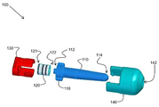
도 1은 시뮬레이션 SMAW 작업을 지원하는 스프링-장착식 팁 조립체의 제1 구현예의 분해도를 도시한다.
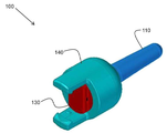
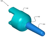
도 2는 도 1의 구현예의 제1 조립도를 도시한다.
도 3은 도 1의 구현예의 제2 조립도를 도시한다.
도 4는 도 1 내지 도 3의 스프링-장착식 팁 조립체의 조립된 구현예의 일부의 잠금 구성을 도시한다.
도 5는 도 1 내지 도 3의 스프링-장착식 팁 조립체의 조립된 구현예의 일부의 비잠금 구성을 도시한다.
도 6은 도 1 내지 도 3의 스프링-장착식 팁 조립체의 조립된 구현예의 단면도를 도시한다.
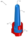
도 7은 시뮬레이션 SMAW 작업을 지원하는 스프링-장착식 팁 조립체의 제2 구현예의 분해도를 도시한다.
도 8은 도 1 내지 도 3의 스프링-장착식 팁 조립체를 구비한 모의 용접 공구의 구현예의 제1 도면을 도시한다.
도 9는 도 8의 모의 용접 공구의 제2 도면을 도시한다.
도 10은 시뮬레이션 SMAW 작업을 지원하는 데에 사용되는 파이프 용접 쿠폰의 구현예를 도시한다.
도 11은 도 10의 파이프 용접 쿠폰에 대한 도 8 및 도 9의 모의 용접 공구의 일 구현예를 도시한다.
도 12는 용접 시뮬레이터에 의해 지원되는 시뮬레이션 SMAW 작업 중에 용접생이 도 10의 파이프 용접 쿠폰 상에 도 8 및 도 9의 모의 용접 공구를 사용하는 예를 도시한다.
도 13은 도 12의 용접 시뮬레이터를 구비한 훈련 용접 시스템의 구현예의 블록도를 도시한다.
도 14는 스프링-장착식 팁 조립체를 조립하는 방법의 제1 구현예의 흐름도를 도시한다.
도 15는 스프링-장착식 팁 조립체를 조립하는 방법의 제2 구현예의 흐름도를 도시한다.BRIEF DESCRIPTION OF THE DRAWINGS The accompanying drawings, which are incorporated in and constitute a part of this specification, illustrate various embodiments of the present disclosure. It will be appreciated that the element boundaries (e.g., boxes, box groups, or other shapes) shown in the figures represent one implementation of the boundaries. In some implementations, one element may be designed with multiple elements, or multiple elements may be designed with one element. In some embodiments, elements depicted as internal components of another element may be implemented as external components, and vice versa. In addition, the elements may not be drawn at the correct ratio.
Figure 1 shows an exploded view of a first embodiment of a spring-mounted tip assembly that supports a simulated SMAW operation.
Figure 2 shows a first assembly view of the embodiment of Figure 1;
Figure 3 shows a second assembly view of the embodiment of Figure 1;
Figure 4 illustrates a locking arrangement of a portion of an assembled embodiment of the spring-mounted tip assembly of Figures 1-3.
Figure 5 illustrates a non-locking configuration of a portion of an assembled embodiment of the spring-mounted tip assembly of Figures 1-3.
Figure 6 shows a cross-sectional view of an assembled embodiment of the spring-loaded tip assembly of Figures 1-3.
Figure 7 shows an exploded view of a second embodiment of a spring-mounted tip assembly that supports a simulated SMAW operation.
Figure 8 shows a first view of an embodiment of a simulated welding tool with the spring-mounted tip assembly of Figures 1-3.
Figure 9 shows a second view of the simulated welding tool of Figure 8;
Figure 10 shows an embodiment of a pipe welding coupon used to support a simulated SMAW operation.
Fig. 11 shows an embodiment of the simulated welding tool of Figs. 8 and 9 for the pipe welding coupon of Fig.
Figure 12 shows an example of using the simulated welding tool of Figures 8 and 9 on a pipe welding coupon of Figure 10 during a simulated SMAW operation supported by a welding simulator.
Figure 13 shows a block diagram of an embodiment of a training welding system with the welding simulator of Figure 12;
Figure 14 shows a flow diagram of a first embodiment of a method of assembling a spring-mounted tip assembly.
Figure 15 shows a flow diagram of a second embodiment of a method of assembling a spring-mounted tip assembly.
스프링-장착식 팁 조립체를 통해 피복 금속 아크 용접(SMAW) 작업의 시뮬레이션을 지원하는 시스템, 장치, 및 방법의 구현예들이 개시된다. 일 구현예에서, 팁 조립체를 구비한 모의 용접 공구를 포함하는 용접 시뮬레이터가 제공된다. 팁 조립체는 근위 단부, 원위 단부, 및 근위 단부 인근의 잠금 슬리브를 구비한 세장형 모의 전극 팁을 포함한다. 압축 스프링이 전극 팁의 근위 단부와 연결되도록 구성된다. 잠금 컵이 압축 스프링 및 잠금 슬리브를 둘러싸도록 구성된다. 오리피스를 구비한 하우징이 잠금 슬리브에 이르기까지 오리피스를 통해 전극 팁의 원위 단부를 받아들임으로써 하우징의 내부에 전극 팁, 압축 스프링, 및 잠금 컵을 수용하도록 구성된다. 잠금 슬리브 및 잠금 컵은 잠금 위치와 비잠금 위치 사이의 변화를 허용하기 위해 서로에 대해 회전하도록 구성된다.Embodiments of a system, apparatus, and method for supporting simulation of Coated Metal Arc Welding (SMAW) operations through a spring-mounted tip assembly are disclosed. In one embodiment, a welding simulator is provided that includes a simulated welding tool with a tip assembly. The tip assembly includes a elongate, mock electrode tip having a proximal end, a distal end, and a locking sleeve proximate the proximal end. And the compression spring is connected to the proximal end of the electrode tip. The lock cup is configured to surround the compression spring and the lock sleeve. A housing with an orifice is configured to receive an electrode tip, a compression spring, and a locking cup in the interior of the housing by receiving the distal end of the electrode tip through the orifice to the locking sleeve. The lock sleeve and lock cup are configured to rotate relative to each other to allow for a change between a locked position and a non-locked position.
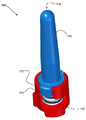
본원의 예들과 도면들은 단지 예시의 목적으로, 청구범위의 정신 및 범주에 의해 평가되는 본 발명을 제한하려는 의도가 아니다. 이제, 본 발명의 예시적인 구현예들을 제한이 아닌 예시의 목적으로 나타낸 도면을 참조하면, 도 1은 시뮬레이션 SMAW 작업을 지원하는 스프링-장착식 팁 조립체(100)의 제1 구현예의 분해도를 도시한다.The examples and figures of the present application are not intended to limit the invention, which is evaluated by the spirit and scope of the claims, for illustrative purposes only. Turning now to the drawings, which illustrate exemplary implementations of the present invention for purposes of illustration and not limitation, Figure 1 shows an exploded view of a first embodiment of a spring-mounted
도 1을 참조하면, 팁 조립체(100)는 세장형 모의 전극 팁(110)을 포함한다. 전극 팁(110)은 근위 단부(112), 원위 단부(114), 및 근위 단부(112) 인근의 잠금 슬리브(116)를 구비한다. 팁 조립체(100)는 또한 제1 단부(122) 및 제2 단부(121)를 구비한 압축 스프링(120)을 포함한다. 제1 단부(122)는 전극 팁(110)의 근위 단부(112)와 연결되도록 구성된다. 예를 들어, 도 1에 도시된 바와 같이, 수형/암형 연결이 제공된다. 팁 조립체(100)는 압축 스프링(120) 및 전극 팁(110)의 잠금 슬리브(116)를 둘러싸도록 구성되는 잠금 컵(130)을 포함한다.Referring to FIG. 1, the
팁 조립체(100)는 오리피스(142)를 구비한 하우징(140)을 포함한다. 하우징(140)은 잠금 슬리브(116)에 이르기까지 오리피스(142)를 통해 전극 팁(110)의 원위 단부(114)를 받아들임으로써 하우징(140)의 내부에 전극 팁(110), 압축 스프링(120), 및 잠금 컵(130)을 수용하도록 구성된다. 전극 팁(110), 압축 스프링(120), 및 잠금 컵(130)이 하우징(140)의 내부에 조립된 상태에서, 도 2 및 도 3에 도시된 바와 같이, 전극 팁(110)의 대부분은 하우징(140)으로부터 오리피스(142) 밖으로 돌출된다. 도 2는 도 1의 구현예의 제1 조립도를 도시하고, 도 3은 도 1의 구현예의 제2 조립도를 도시한다.The
일 구현예에 따르면, 잠금 슬리브(116) 및 잠금 컵(130)은 잠금 위치와 비잠금 위치 사이의 변화를 허용하기 위해 서로에 대해 회전하도록 구성된다. 도 4는 도 1 내지 도 3의 스프링-장착식 팁 조립체(100)의 조립된 구현예의 일부의 잠금 구성(400)을 도시하는데, 잠금 위치의 전극 팁(110)과 잠금 컵(130)을 보여준다. 도 5는 도 1 내지 도 3의 스프링-장착식 팁 조립체(100)의 조립된 구현예의 일부의 비잠금 구성(500)을 도시하는데, 비잠금 위치의 전극 팁(110)과 잠금 컵(130)을 보여준다.According to one embodiment,
도 4에서, 압축 스프링(120)은 잠금 위치에 있는데, 압축되어 잠금 슬리브(116) 및 잠금 컵(130)에 의해 완전히 둘러싸여 있기 때문에 도 4에 나타나지 않는다. 일 구현예에서, 압축 스프링(120)은 잠금 위치에서 완전 압축 상태이며, 전극 팁(110)은 잠금 컵(130) 및 하우징(140)에 대해 고정 상태이다(잠금된다). 잠금 위치를 달성하기 위해, 일 구현예에서, 사용자는 하우징(140) 내로 전극팁(110)을 최대한 밀어넣은 후에, 잠금 컵(130)에 대해 전극 팁(110)을 회전시킨다. 도 4에서 알 수 있는 바와 같이, 잠금 슬리브(116)의 일부는 팁 조립체(100)가 잠금 위치가 되도록 잠금 컵(130)의 슬롯과 맞물린다. 다른 구현예들에 따르면, 다른 균등한 잠금 구성도 역시 가능하다. 이런 방식으로, 잠금 위치가 시뮬레이션 SMAW 파이프 용접 작업을 지원하기 위해 제공된다.4, the
도 5에서, 압축 스프링(120)은 비잠금 위치가 되어, 압축 스프링(120)은 자유 상태가 된다. 도 5에서 알 수 있는 바와 같이, 잠금 슬리브(116)는 잠금 컵(130)의 슬롯과 더 이상 맞물리지 않는다. 자유 상태는 전극 팁(110)의 원위 단부(114)가 하우징(140) 쪽으로 밀림에 따라(예를 들어, 용접생이 팁 조립체(100)가 부착된 모의 용접 공구를 통해 시뮬레이션 SMAW 파이프 용접 작업 중에 파이프 용접 쿠폰의 조인트 내로 전극 팁(110)의 원위 단부(114)를 밀어넣음에 따라) 압축 스프링(120)이 압축될 수 있게 한다. 자유 상태는 또한 하우징(140)으로부터 멀리 전극 팁(110)의 원위 단부(114)를 밀기 위해(예를 들어, 용접생이 시뮬레이션 SMAW 파이프 용접 작업 중에 파이프 용접 쿠폰의 조인트로부터 멀리 팁 조립체(100)가 부착된 모의 용접 공구를 당김에 따라) 압축 스프링(120)이 압축해제될 수 있게 한다. 이런 방식으로, 시뮬레이션 SMAW 작업 중에 전극 팁(110)이 파이프 용접 쿠폰과 맞물림에 따라 파이프 상에 실제 SMAW 작업을 수행하는 느낌을 시뮬레이션하기 위해 촉각 피드백이 용접생에게 제공된다.In Fig. 5, the
도 6은 도 1 내지 도 3의 스프링-장착식 팁 조립체(100)의 조립된 구현예의 단면도를 도시한다. 도 6에 나타낸 바와 같이, 하우징(140)은 팁 조립체(100)가 모의 용접 공구에 부착 및 탈착될 수 있게 하는 부착부(600)를 포함하는데, 이는 본원에서 추후 논의될 것이다. 도 6의 부착부(600)는 클립온 또는 스냅온 구성의 형태이다. 다른 구현예들에 따르면, 다른 균등한 부착부 구성도 역시 가능하다.Figure 6 shows a cross-sectional view of an assembled embodiment of the spring-loaded
전극 팁(110)은 시뮬레이션 SMAW 작업 중에 전극 팁(110)과 용접 쿠폰 사이의 미끄러짐을 완화하도록 구성되는 재료로 이루어진다. 예를 들어, 일 구현예에서, 전극 팁(110)의 적어도 원위 단부(114)는 폴리옥시메틸렌 재료로 이루어진다. 폴리옥시메틸렌 재료는 필요시 미끄러짐을 완화한다. 일 구현예에 따르면, 압축 스프링(120)의 적어도 일부는 폴리에테르이미드 재료로 이루어진다. 폴리에테르이미드 재료는 시뮬레이션 SMAW 작업에 적용하기 위해 원하는 압축 스프링 특성을 제공한다. 다른 구현예들에 따르면, 다른 균등한 재료도 역시 가능할 수 있다.The
도 7은 시뮬레이션 SMAW 작업을 지원하는 스프링-장착식 팁 조립체(700)의 제2 구현예의 분해도를 도시한다. 도 7의 팁 조립체(700)는 팁 조립체(700)가 압력 센서 변환기(710)를 추가로 포함하는 것을 제외하면 이전 도면의 팁 조립체(100)와 유사하다. 압력 센서 변환기(710)는, 압축 스프링(120)의 압축량을 감지하고 압축 스프링(120)의 압축량을 나타내는 신호를 발생시키기 위해 압축 스프링(120)의 제2 단부(121)와 연결되도록 구성된다. 일 구현예에 따르면, 압력 센서 변환기(710)는 압전 기술을 이용한다. 다른 구현예들에서, 압력 센서 변환기(710)는 다른 유형의 센서 및 변환기 기술을 이용할 수 있다. 컵(130)은 압력 센서 변환기(710), 압축 스프링(120), 및 전극 팁(110)의 슬리브(116)를 둘러싸도록 구성된다. 하우징(140)은 도 1 내지 도 3과 유사한 방식으로 하우징의 내부에 전극 팁(110), 압축 스프링(120), 압력 센서 변환기(710), 및 컵(130)을 수용하도록 구성된다.Figure 7 illustrates an exploded view of a second embodiment of a spring-mounted
일 구현예에서, 팁 조립체(700)의 컵(130) 및 슬리브(116)는 도 1 내지 도 3과 유사한 잠금 컵 및 잠금 슬리브이다. 그러나, 대안적인 구현예에서, 팁 조립체(700)의 컵(130) 및 슬리브(116)는 본원에 전술한 바와 같이 잠금 위치와 비잠금 위치 사이의 변화 능력을 제공하지 않는다. 그 대신, 전극 팁(110)은 시뮬레이션 SMAW 파이프 용접 작업을 지원하기 위해 항상 비잠금되고 (본원에 전술한) 자유 상태이다.In one embodiment,
일 구현예에 따르면, 압축 스프링(120)의 압축량을 나타내도록 압력 센서 변환기(710)에 의해 발생되는 신호는 적어도 하나의 시뮬레이션 아크 특성을 나타낸다. 시뮬레이션 아크 특성은 아크 전압, 아크 전류, 아크 길이(아크 거리), 또는 소멸 아크일 수 있다. 신호는 용접 시뮬레이터에 (유선 또는 무선으로) 제공될 수 있는데, 이는 본원에서 추후 논의되는 바와 같이 신호를 적어도 하나의 아크 특성과 상호 관련시키고 상호 관계에 기반하여 응답을 발생시키도록 구성된다. 다양한 구현예들에 따르면, 신호는 아날로그 신호 및/또는 디지털 신호일 수 있다.According to one embodiment, the signal generated by the
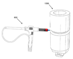
도 8은 도 1의 스프링-장착식 팁 조립체(100) 또는 도 7의 스프링-장착식 팁 조립체(700)를 구비한 모의 용접 공구(800)의 구현예의 제1 도면을 도시한다. 도 9는 도 8의 모의 용접 공구(800)의 일부의 제2 도면을 도시한다. 모의 용접 공구(800)는 용접생이 잡도록 구성되는 핸들(810)을 포함한다. 모의 용접 공구(800)는 또한, 핸들(810)에 작동 가능하게 연결되며 용접 시뮬레이터에 활성 용접 상태를 나타내도록 구성되는 트리거(820)를 포함한다. 예를 들어, 일 구현예에서, 용접생이 트리거(820)를 누를 때, 전기 신호가 모의 용접 공구(800)로부터 용접 시뮬레이터로 유선 또는 무선 송신되어, 시뮬레이션(예를 들어, 가상 현실) 용접 작업을 활성화한다. 용접 시뮬레이터는 본원에서 추후 보다 상세히 논의될 것이다. 핸들(810) 및 트리거(820)는 일 구현예에서는 오른손잡이 용접생을 위해, 다른 구현예에서는 왼손잡이 용접생을 위해 구성될 수 있다.FIG. 8 illustrates a first view of an embodiment of a
모의 용접 공구(800)는 또한 스프링-장착식 팁 조립체(100 또는 700)가 그 일부에 부착된 모의 스틱 전극(830)을 포함한다. 다양한 구현예들에 따르면, 팁 조립체(100 또는 700)는 본원에 전술한 바와 같고, 팁 조립체(100 또는 700)의 부착부(600; 예를 들어, 또한 도 6 및 도 7 참조)를 통해 부착된다(그리고 착탈 가능하다). 일 구현예에 따르면, 부착부(600)는 모의 용접 공구(800)에 클립온 또는 스냅온되도록 구성된다. 다른 구현예들에서, 부착부는 모의 용접 공구 상에 트위스트 또는 슬라이드되어 잠금되도록 구성될 수 있다. 다른 부착 구현예들도 역시 가능하다. 게다가, 일 구현예에서, 팁 조립체(100 또는 700)는 모의 용접 공구(800)에 연결되는 어댑터로 구성된다. 모의 용접 공구(800)는 예를 들어 다른 유형의 용접 또는 절삭의 시뮬레이션을 위해 다른 어댑터 공구 구성의 부착을 지원할 수도 있다.The
모의 용접 공구(800)는 용접생의 트리거(820) 활성화(예를 들어, 누름 또는 당김)에 응답하여 용접생 쪽으로 모의 스틱 전극(830)을 인입 또는 회수하도록 구성되는 액추에이터 조립체(840)를 포함한다. 모의 스틱 전극(830)의 인입 또는 회수는 SMAW 작업 중에 실제 스틱 전극의 소모를 시뮬레이션한다. 일 구현예에 따르면, 액추에이터 조립체(840)는 전기 모터를 포함한다.The
일 구현예에서, 모의 용접 공구(800)는 용접 시뮬레이터가 적어도 3차원 공간의 위치 및 배향으로 모의 용접 공구(800)를 추적하는 데에 도움이 되는 적어도 하나의 센서(850)를 포함한다. 특정 구현예들에 따르면, 센서 및 추적 기술은 예를 들어 가속도계, 자이로, 자석, 전도성 코일, 레이저, 초음파, 무선 주파수 장치, 및 스캐닝 시스템 중 하나 이상을 포함할 수 있다. 공간적 추적 능력을 갖는 용접 시뮬레이터의 예가 미국 특허 제8,915,740호에 기재되어 있고, 그 전체가 본원에 참조로 포함된다.In one embodiment, the
일 구현예에서, 모의 용접 공구(800)는 용접 시뮬레이터와 통신하도록 구성되는 통신 모듈(860)을 포함한다. 다양한 구현예들에 따르면, 모의 용접 공구(800)와 용접 시뮬레이터 사이의 통신은 무선으로(예를 들어, 무선 주파수 또는 적외선을 통해) 또는 유선 수단을 통해(예를 들어, 전기 케이블을 통해) 일어날 수 있다. 통신 모듈(860)은 모의 용접 공구(800)로부터 용접 시뮬레이터로, 트리거(820)가 활성화될 때 발생되는 전기 신호의 통신을 용이하게 할 수 있다. 통신 모듈(860)은 또한 모의 용접 공구(800)로부터 용접 시뮬레이터로, (모의 용접 공구(800)의 위치 및 배향을 나타내는) 센서(850)에 의해 발생되는 센서 신호의 통신을 용이하게 할 수 있다. 일 구현예에서, 통신 모듈(860)은 용접 시뮬레이터로부터 모의 용접 공구(800)로 경고 및 경보 신호의 통신을 용이하게 할 수 있다. 예를 들어, 모의 용접 공구(800)는 경고 및 경보 신호에 응답하여 용접생에게 경고 및 경보를 발하는 발광 다이오드(LED) 및/또는 음향-발생 변환기를 포함할 수 있다.In one implementation, the
도 10은 시뮬레이션 SMAW 파이프 용접 작업을 지원하는 데에 사용되는 파이프 용접 쿠폰(1000)의 구현예를 도시한다. 파이프 용접 쿠폰(1000)은 쿠폰(1000)에 외접하는 조인트(1010)를 포함한다. 도 11은 시뮬레이션 SMAW 파이프 용접 작업의 일부로 조인트(1010)의 용접을 시뮬레이션하기 위해 도 10의 파이프 용접 쿠폰(1000)에 대한 도 8 및 도 9의 모의 용접 공구(800)의 일 구현예를 도시한다. 모의 용접 공구(800)의 스프링-장착식 팁 조립체는 용접 쿠폰에서 미끄러짐을 완화하며 용접생에게 압력-기반 촉각 피드백을 제공한다.10 illustrates an embodiment of a
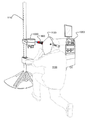
도 12는 용접 시뮬레이터(1200)에 의해 지원되는 시뮬레이션 SMAW 작업 중에 용접생(1100)이 도 10의 파이프 용접 쿠폰(1000) 상에 도 8 및 도 9의 모의 용접 공구(800)를 사용하는 예를 도시한다. 도 12에 도시된 바와 같이, 파이프 용접 쿠폰(1000)은 용접생(1100)을 위해 원하는 위치에 파이프 용접 쿠폰을 유지하는 용접 스탠드(1110)에 의해 지지된다. 도 12에서, 용접생(1100)은 가상 현실 용접 헬멧 또는 얼굴 착용형 디스플레이 장치(FMDD; 1120)를 착용하고 있는데, 이는 모의 용접 공구(800)와 함께 용접 시뮬레이터(1200)에 통신 가능하게 연결된다. 특정 구현예들에서, 용접 시뮬레이터(1200)는, 용접생(1100)이 모의 용접 공구(800)를 사용하여 파이프 용접 쿠폰(1000) 상에 시뮬레이션 SMAW 파이프 용접을 실시함에 따라, 용접생(1100)이 FMDD(1120) 내의 디스플레이 장치 상에서 볼 수 있는 증강 현실 및/또는 가상 현실 환경을 용접생에게 제공한다. 다시, 모의 용접 공구(800)의 스프링-장착식 팁 조립체는 시뮬레이션 피복 금속 아크 용접 작업 중에 전극 팁이 파이프 용접 쿠폰(1000)과 맞물림에 따라 파이프 상에 실제 피복 금속 아크 용접 작업을 수행하는 느낌을 시뮬레이션하기 위해 용접생(1100)에게 촉각 피드백을 제공한다.12 illustrates an example of using the
도 13은 도 12의 용접 시뮬레이터(1200), 용접 쿠폰(1000), 용접 테이블/스탠드(1110), FMDD(1120), 및 모의 용접 공구(800)를 포함하는 훈련 용접 시스템(1300)의 구현예의 블록도를 도시한다. 용접 시뮬레이터(1200)는 프로그램가능 프로세서-기반 서브시스템(PPS; 1210), 공간적 추적기(ST; 1220), 용접 사용자 인터페이스(WUI; 1230), 및 관찰자 디스플레이 장치(ODD; 1240)를 포함한다. PPS(1210), ST(1220), WUI(1230), ODD(1240)(및 FMDD(1120), 용접 쿠폰(1000), 및 용접 테이블/스탠드(1110))의 구현예들의 상세한 설명은 미국 특허 제8,915,740호에서 발견할 수 있고, 그 전체가 본원에 참조로 포함된다. 대응하는 부품들에 대해, 본원에 사용된 것과 상이한 참조 번호들이 미국 특허 제8,915,740호에 사용될 수 있음을 주목한다.Figure 13 shows an embodiment of a
본원에 전술한 바와 같이, 일 구현예에 따르면, 압축 스프링(120)의 압축량을 나타내도록 압력 센서 변환기(710)에 의해 발생되는 신호는 적어도 하나의 시뮬레이션 아크 특성을 나타낸다. 시뮬레이션 아크 특성은 예를 들어 아크 전압, 아크 전류, 아크 길이(아크 거리), 또는 소멸 아크일 수 있다. 신호는 용접 시뮬레이터(1200)에 (유선 또는 무선으로) 제공될 수 있는데, 이는 신호를 적어도 하나의 아크 특성과 상호 관련시키고 상호 관계에 기반하여 응답을 발생시키도록 구성된다. 다양한 구현예들에 따르면, 신호는 아날로그 신호 및/또는 디지털 신호일 수 있다.As described hereinabove, according to one embodiment, the signal generated by the
예를 들어, 신호는, 전극 팁(110)이 파이프 용접 쿠폰(1000)의 조인트(1010) 내로 너무 많이 밀렸고, 현실 시계에서는 그 결과 아크가 소멸된 것을 나타내는 "아크 소멸" 특성과 상호 관련될 수 있다. 다른 예로, 신호는, 아크 거리가 너무 짧거나 너무 길고, 용접생이 적절한 아크 거리를 달성하기 위해 조인트(1010)에 대해 모의 용접 공구(800)의 위치를 조절해야 함을 나타내는 "아크 거리" 특성과 상호 관련될 수 있다. 일 구현예에 따르면, 용접 시뮬레이터(1200)는 이와 같은 아크 특성들에 기반하여 용접생에게 다양한 경보 및 경고를 제공할 수 있다. 또한, 용접 시뮬레이터(1200)는 용접생이 다양한 아크 특성들에 대해 "제한 범위를 벗어날 때" 용접생의 점수에 벌점을 적용할 수 있다.For example, the signal may be correlated to an "arc extinction" property, which indicates that the
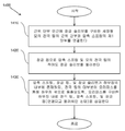
도 14는 스프링-장착식 팁 조립체(100)를 조립하는 방법(1400)의 제1 구현예의 흐름도를 도시한다. 도 14의 블록(1410)에서, 근위 단부 인근에 잠금 슬리브를 구비한 세장형 모의 전극 팁의 근위 단부와 압축 스프링의 제1 단부를 연결한다. 블록(1420)에서, 잠금 컵으로 압축 스프링 및 모의 전극 팁의 적어도 잠금 슬리브를 둘러싼다. 블록(1430)에서, 압축 스프링, 잠금 컵, 및 잠금 슬리브가 하우징의 내부에 존재하되, 모의 전극 팁의 대부분이 오리피스를 통해 하우징 밖으로 돌출되도록, 오리피스를 구비한 하우징 내로 전극 팁, 압축 스프링, 및 잠금 컵(연결되고 둘러싸인 상태)을 삽입한다. 블록들(1410~1430)은 스프링-장착식 팁 조립체(100)의 동일한 최종 조립 구성을 초래하는 대안적인 순서 또는 주어진 순서로 수행될 수 있다.14 shows a flow diagram of a first embodiment of a
도 15는 스프링-장착식 팁 조립체(700)를 조립하는 방법(1500)의 제2 구현예의 흐름도를 도시한다. 블록(1510)에서, 근위 단부 인근에 잠금 슬리브를 구비한 세장형 모의 전극 팁의 근위 단부와 압축 스프링의 제1 단부를 연결한다. 블록(1520)에서, 압축 스프링의 제2 단부와 압력 센서 변환기를 연결한다. 블록(1530)에서, 잠금 컵으로 압력 센서 변환기, 압축 스프링, 및 모의 전극 팁의 적어도 잠금 슬리브를 둘러싼다. 블록(1540)에서, 압축 스프링, 압력 센서 변환기, 잠금 컵, 및 잠금 슬리브가 하우징의 내부에 존재하되, 전극 팁의 대부분이 오리피스를 통해 하우징 밖으로 돌출되도록, 오리피스를 구비한 하우징 내로 전극 팁, 압축 스프링, 압력 센서 변환기, 및 잠금 컵(연결되고 둘러싸인 상태)을 삽입한다. 블록들(1510~1540)은 스프링-장착식 팁 조립체(700)의 동일한 최종 조립 구성을 초래하는 대안적인 순서 또는 주어진 순서로 수행될 수 있다.15 shows a flow diagram of a second embodiment of a
개시된 구현예들이 상당히 상세히 도시되고 설명되었지만, 이는 이와 같은 상세로 첨부된 청구범위의 범주를 한정하거나 어떤 방식으로든 제한하기 위한 의도가 아니다. 물론, 본 주제의 다양한 양태들을 설명하기 위해 부품들 또는 방법들의 모든 있음직한 조합을 기술할 수는 없다. 그러므로, 본 개시는 도시되고 설명된 특정 상세 또는 예시적인 예에 제한되지 않는다. 따라서, 본 개시는 35 U.S.C. §101의 실정법상 주제 요건을 충족시키는 첨부된 청구범위의 범주에 속하는 교체, 수정, 및 변경을 포괄하도록 의도된 것이다. 특정 구현예들의 상기 설명은 예로서 주어졌다. 주어진 개시로부터, 당업자들은 일반적인 발명의 개념 및 수반된 이점을 이해할 뿐만 아니라, 개시된 구조 및 방법에 대한 명백한 다양한 변경 및 수정을 발견할 것이다. 그러므로, 첨부된 청구범위에 의해 정의된 바와 같이, 일반적인 발명의 개념의 정신 및 범주에 속하는 이 모든 변경 및 수정과 그 균등물을 포괄하고자 한다.Although the disclosed embodiments have been shown and described in considerable detail, it is not intended to limit or in any way limit the scope of the appended claims to such detail. Of course, not every possible combination of parts or methods can be described to illustrate various aspects of the subject matter. Therefore, the present disclosure is not limited to the specific details or illustrative examples shown and described. Accordingly, this disclosure is directed to 35 U.S.C. It is intended to cover alternatives, modifications and variations that fall within the scope of the appended claims, which fulfill the subject matter of the Acts of Section 101. The foregoing description of specific implementations has been given by way of example. From a given disclosure, those skilled in the art will appreciate not only the general inventive concept and the attendant advantages, but also obvious variations and modifications to the disclosed structure and method. Therefore, it is intended to embrace all such alterations, modifications and equivalents as are within the spirit and scope of the general inventive concept as defined by the appended claims.
Claims (20)
근위 단부, 원위 단부, 및 상기 근위 단부 인근의 잠금 슬리브를 구비한 세장형 모의 전극 팁;
제1 단부 및 제2 단부를 구비하되, 상기 제1 단부는 상기 전극 팁의 상기 근위 단부와 연결되도록 구성되는 압축 스프링;
상기 압축 스프링 및 상기 전극 팁의 상기 잠금 슬리브를 둘러싸도록 구성되는 잠금 컵; 및
오리피스를 구비한 하우징으로, 상기 하우징은 상기 잠금 슬리브에 이르기까지 상기 하우징의 상기 오리피스를 통해 상기 전극 팁의 상기 원위 단부를 받아들임으로써 상기 하우징 내에 상기 전극 팁, 상기 압축 스프링, 및 상기 잠금 컵을 수용하도록 구성되고, 그 결과 상기 압축 스프링, 상기 잠금 컵, 및 상기 잠금 슬리브가 상기 하우징의 내부에 존재하되, 상기 전극 팁의 대부분이 상기 하우징 밖으로 돌출되는 하우징을 포함하고,
상기 잠금 슬리브 및 상기 잠금 컵은 잠금 위치와 비잠금 위치 사이의 변화를 허용하기 위해 서로에 대해 회전하도록 구성되는, 팁 조립체.A tip assembly for supporting simulation of a coated metal arc welding operation,
A elongated simulated electrode tip having a proximal end, a distal end, and a locking sleeve proximate the proximal end;
A compression spring having a first end and a second end, the first end being configured to couple with the proximal end of the electrode tip;
A locking cup configured to surround the compression spring and the locking sleeve of the electrode tip; And
A housing having an orifice that receives the distal end of the electrode tip through the orifice of the housing until reaching the locking sleeve, thereby housing the electrode tip, the compression spring, and the locking cup within the housing Wherein the compression spring, the locking cup, and the locking sleeve are internal to the housing, wherein a majority of the electrode tip protrudes out of the housing,
Wherein the locking sleeve and the locking cup are configured to rotate relative to each other to permit a change between a locked position and a non-locked position.
파이프 용접 쿠폰의 시뮬레이션 피복 금속 아크 용접에 사용하기 위해, 상기 잠금 위치는 상기 잠금 컵 내에서 완전 압축 상태로 상기 압축 스프링을 유지하는 한편, 상기 잠금 컵 및 상기 하우징에 대해 고정 상태로 상기 전극 팁을 유지하는, 팁 조립체.The method according to claim 1,
Simulation of a pipe welding coupon For use in metal arc welding, the locking position maintains the compression spring in a fully compressed state in the locking cup, while the locking tip is held in a fixed position relative to the locking cup and the housing The tip assembly.
상기 비잠금 위치는 상기 압축 스프링이 자유 상태가 되게 하여, 상기 전극 팁의 상기 원위 단부가 상기 하우징 쪽으로 밀림에 따라 상기 압축 스프링이 압축될 수 있게 하며, 상기 하우징으로부터 멀리 상기 전극 팁의 상기 원위 단부를 밀기 위해 상기 압축 스프링이 압축해제될 수 있게 하여, 그 결과 시뮬레이션 피복 금속 아크 용접 작업 중에 상기 전극 팁이 파이프 용접 쿠폰과 맞물림에 따라 파이프 상에 실제 피복 금속 아크 용접 작업을 수행하는 느낌을 시뮬레이션하기 위해 용접생에게 촉각 피드백을 제공하는, 팁 조립체.The method according to claim 1,
Wherein the non-locking position causes the compression spring to be in a free state such that the compression spring can be compressed as the distal end of the electrode tip is pushed toward the housing and the distal end To simulate the feel of performing an actual sheathing metal arc welding operation on the pipe as the electrode tip engages the pipe weld coupon during the simulated sheathing metal arc welding operation Wherein the tip assembly provides tactile feedback to the welder.
상기 하우징은 시뮬레이션 피복 금속 아크 용접 작업에 사용하기 위해 모의 용접 공구에 착탈 가능하게 부착되도록 구성되는, 팁 조립체.The method according to claim 1,
Wherein the housing is configured to be removably attached to a simulated welding tool for use in a simulated sheathed metal arc welding operation.
상기 전극 팁의 적어도 상기 원위 단부는 시뮬레이션 피복 금속 아크 용접 작업 중에 상기 전극 팁과 용접 쿠폰 사이의 미끄러짐을 완화하도록 구성되는 재료로 이루어지는, 팁 조립체.The method according to claim 1,
Wherein at least the distal end of the electrode tip is made of a material configured to alleviate slippage between the electrode tip and the weld coupon during a simulated clad metal arc welding operation.
상기 압축 스프링의 적어도 일부는 폴리에테르이미드로 이루어지는, 팁 조립체.The method according to claim 1,
Wherein at least a portion of the compression spring comprises a polyetherimide.
상기 전극 팁의 적어도 일부는 폴리옥시메틸렌으로 이루어지는, 팁 조립체.The method according to claim 1,
Wherein at least a portion of the electrode tip is made of polyoxymethylene.
근위 단부, 원위 단부, 및 상기 근위 단부 인근의 슬리브를 구비한 세장형 모의 전극 팁;
제1 단부 및 제2 단부를 구비하되, 상기 제1 단부는 상기 전극 팁의 근위 단부와 연결되도록 구성되는 압축 스프링;
상기 압축 스프링의 압축량을 감지하고 상기 압축 스프링의 상기 압축량을 나타내는 신호를 발생시키기 위해 상기 압축 스프링의 상기 제2 단부와 연결되도록 구성되는 압력 센서 변환기;
상기 압력 센서 변환기, 상기 압축 스프링, 및 상기 전극 팁의 상기 슬리브를 둘러싸도록 구성되는 컵; 및
오리피스를 구비한 하우징으로, 상기 하우징은 상기 슬리브에 이르기까지 상기 하우징의 상기 오리피스를 통해 상기 전극 팁의 상기 원위 단부를 받아들임으로써 상기 하우징 내에 상기 전극 팁, 상기 압축 스프링, 상기 압력 센서 변환기, 및 상기 컵을 수용하도록 구성되고, 그 결과 상기 압력 센서 변환기, 상기 압축 스프링, 상기 컵, 및 상기 슬리브가 상기 하우징의 내부에 존재하되, 상기 전극 팁의 대부분이 상기 하우징 밖으로 돌출되는 하우징을 포함하는, 팁 조립체.A tip assembly for supporting simulation of a coated metal arc welding operation,
A elongate simulated electrode tip having a proximal end, a distal end, and a sleeve proximate said proximal end;
A compression spring having a first end and a second end, the first end being configured to be connected to the proximal end of the electrode tip;
A pressure sensor converter configured to be coupled to the second end of the compression spring to sense a compression amount of the compression spring and to generate a signal indicative of the compression amount of the compression spring;
A cup configured to surround the pressure sensor transducer, the compression spring, and the sleeve of the electrode tip; And
A housing having an orifice, the housing receiving the distal end of the electrode tip through the orifice of the housing until reaching the sleeve so that the electrode tip, the compression spring, the pressure sensor transducer, And a housing in which the pressure sensor transducer, the compression spring, the cup, and the sleeve reside within the housing, wherein a majority of the electrode tip protrudes out of the housing, Assembly.
상기 압축 스프링의 상기 압축량을 나타내는 상기 신호는 적어도 하나의 시뮬레이션 아크 특성을 나타내는, 팁 조립체.9. The method of claim 8,
Wherein the signal indicative of the amount of compression of the compression spring exhibits at least one simulated arc characteristic.
상기 적어도 하나의 시뮬레이션 아크 특성은 아크 전압, 아크 전류, 아크 길이, 및 소멸 아크 중 적어도 하나를 포함하는, 팁 조립체.10. The method of claim 9,
Wherein the at least one simulated arc characteristic comprises at least one of an arc voltage, an arc current, an arc length, and an extinction arc.
상기 슬리브 및 상기 컵은 잠금 위치와 비잠금 위치 사이의 변화를 허용하기 위해 서로에 대해 회전하도록 구성되는, 팁 조립체.9. The method of claim 8,
Wherein the sleeve and the cup are configured to rotate relative to each other to permit a change between a locked position and a non-locked position.
파이프 용접 쿠폰의 시뮬레이션 피복 금속 아크 용접 작업 중에 사용하기 위해, 상기 잠금 위치는 상기 컵 내에서 완전 압축 상태로 상기 압축 스프링을 유지하는 한편, 상기 컵 및 상기 하우징에 대해 고정 상태로 상기 전극 팁을 유지하는, 팁 조립체.12. The method of claim 11,
Simulation of pipe welding coupons For use during metal arc welding operations, the locking position maintains the compression spring in a fully compressed state within the cup while maintaining the electrode tip in a fixed position relative to the cup and the housing Lt; / RTI >
상기 비잠금 위치는 상기 압축 스프링이 자유 상태가 되게 하여, 상기 전극 팁의 상기 원위 단부가 상기 하우징 쪽으로 밀림에 따라 상기 압축 스프링이 압축될 수 있게 하며, 상기 하우징으로부터 멀리 상기 전극 팁의 상기 원위 단부를 밀기 위해 상기 압축 스프링이 압축해제될 수 있게 하고, 그 결과 시뮬레이션 피복 금속 아크 용접 작업 중에 상기 전극 팁이 파이프 용접 쿠폰과 맞물림에 따라 파이프 상에 실제 피복 금속 아크 용접 작업을 수행하는 느낌을 시뮬레이션하기 위해 용접생에게 촉각 피드백을 제공하는, 팁 조립체.12. The method of claim 11,
Wherein the non-locking position causes the compression spring to be in a free state such that the compression spring can be compressed as the distal end of the electrode tip is pushed toward the housing and the distal end To simulate the feeling of performing an actual sheathing metal arc welding operation on the pipe as the electrode tip engages the pipe welding coupon during a simulated sheathing metal arc welding operation Wherein the tip assembly provides tactile feedback to the welder.
용접생이 잡도록 구성되는 핸들;
상기 핸들에 작동 가능하게 연결되며 용접 시뮬레이터에 활성 용접 상태를 나타내도록 구성되는 트리거; 및
팁 조립체를 구비한 모의 스틱 전극을 포함하되, 상기 팁 조립체는:
근위 단부, 원위 단부, 및 상기 근위 단부 인근의 잠금 슬리브를 구비한 세장형 모의 전극 팁,
제1 단부 및 제2 단부를 구비하되, 상기 제1 단부는 상기 전극 팁의 상기 근위 단부와 연결되도록 구성되는 압축 스프링,
상기 압축 스프링 및 상기 전극 팁의 상기 잠금 슬리브를 둘러싸도록 구성되는 잠금 컵, 및
오리피스를 구비한 하우징으로, 상기 하우징은 상기 잠금 슬리브에 이르기까지 상기 하우징의 상기 오리피스를 통해 상기 전극 팁의 상기 원위 단부를 받아들임으로써 상기 하우징 내에 상기 전극 팁, 상기 압축 스프링, 및 상기 잠금 컵을 수용하도록 구성되고, 그 결과 상기 압축 스프링, 상기 잠금 컵, 및 상기 잠금 슬리브가 상기 하우징의 내부에 존재하되, 상기 전극 팁의 대부분이 하우징 밖으로 돌출되는 하우징을 포함하고,
상기 잠금 슬리브 및 상기 잠금 컵은 잠금 위치와 비잠금 위치 사이의 변화를 허용하기 위해 서로에 대해 회전하도록 구성되는, 모의 용접 공구.A simulated welding tool for supporting simulation of a coated metal arc welding operation,
A handle configured to hold the weld;
A trigger operatively connected to the handle and configured to present an active weld state to the weld simulator; And
A tip assembly having a tip assembly, the tip assembly comprising:
A elongate simulated electrode tip having a proximal end, a distal end, and a locking sleeve proximate the proximal end,
A compression spring having a first end and a second end, the first end being configured to couple with the proximal end of the electrode tip,
A locking cup configured to surround the compression spring and the locking sleeve of the electrode tip,
A housing having an orifice that receives the distal end of the electrode tip through the orifice of the housing until reaching the locking sleeve, thereby housing the electrode tip, the compression spring, and the locking cup within the housing Wherein the compression spring, the locking cup, and the locking sleeve are internal to the housing, wherein a majority of the electrode tip protrudes out of the housing,
Wherein the locking sleeve and the locking cup are configured to rotate relative to each other to permit a change between a locked position and a non-locked position.
파이프 용접 쿠폰의 시뮬레이션 피복 금속 아크 용접 작업에 사용하기 위해, 상기 잠금 위치는 상기 잠금 컵 내에서 완전 압축 상태로 상기 압축 스프링을 유지하는 한편, 상기 잠금 컵 및 상기 하우징에 대해 고정 상태로 상기 전극 팁을 유지하는, 모의 용접 공구.15. The method of claim 14,
Simulation of a pipe welding coupon For use in an arc welding operation, the locking position maintains the compression spring in a fully compressed state within the locking cup, while maintaining the compression spring in a fixed position relative to the locking cup and the housing, , A simulation tool.
상기 비잠금 위치는 상기 압축 스프링이 자유 상태가 되게 하여, 상기 전극 팁의 상기 원위 단부가 상기 하우징 쪽으로 밀림에 따라 상기 압축 스프링이 압축될 수 있게 하며, 상기 하우징으로부터 멀리 상기 전극 팁의 상기 원위 단부를 밀기 위해 상기 압축 스프링이 압축해제될 수 있게 하고, 그 결과 시뮬레이션 피복 금속 아크 용접 작업 중에 상기 전극 팁이 파이프 용접 쿠폰과 맞물림에 따라 파이프 상에 실제 피복 금속 아크 용접 작업을 수행하는 느낌을 시뮬레이션하기 위해 용접생에게 촉각 피드백을 제공하는, 모의 용접 공구.15. The method of claim 14,
Wherein the non-locking position causes the compression spring to be in a free state such that the compression spring can be compressed as the distal end of the electrode tip is pushed toward the housing and the distal end To simulate the feeling of performing an actual sheathing metal arc welding operation on the pipe as the electrode tip engages the pipe welding coupon during a simulated sheathing metal arc welding operation A simulated welding tool that provides tactile feedback to the welder.
상기 용접 시뮬레이터가 적어도 3차원 공간의 위치 및 배향으로 상기 모의 용접 공구를 추적하는 데에 도움이 되는 적어도 하나의 센서를 추가로 포함하는, 모의 용접 공구.15. The method of claim 14,
Wherein the weld simulator further comprises at least one sensor to help track the simulated weld tool in at least three dimensional space location and orientation.
실제 스틱 전극의 소모를 시뮬레이션하기 위해 상기 용접생의 트리거 활성화에 응답하여 상기 용접생 쪽으로 상기 모의 스틱 전극을 인입하도록 구성되는 액추에이터 조립체를 추가로 포함하는, 모의 용접 공구.15. The method of claim 14,
Further comprising an actuator assembly configured to draw the simulated stick electrode toward the weld bead in response to trigger activation of the weld bead to simulate consumption of the actual stick electrode.
상기 용접 시뮬레이터와 무선 통신하도록 구성되는 통신 모듈을 추가로 포함하는, 모의 용접 공구.15. The method of claim 14,
Further comprising a communication module configured to wirelessly communicate with the welding simulator.
상기 모의 용접 공구와 상기 용접 시뮬레이터 사이에 연결되는 케이블을 통해 상기 용접 시뮬레이터와 통신하도록 구성되는 통신 모듈을 추가로 포함하는, 모의 용접 공구.
15. The method of claim 14,
Further comprising a communications module configured to communicate with the weld simulator via a cable connected between the simulated weld tool and the weld simulator.
Applications Claiming Priority (4)
| Application Number | Priority Date | Filing Date | Title |
|---|---|---|---|
| US201762513584P | 2017-06-01 | 2017-06-01 | |
| US62/513,584 | 2017-06-01 | ||
| US15/696,495 | 2017-09-06 | ||
| US15/696,495 US10997872B2 (en) | 2017-06-01 | 2017-09-06 | Spring-loaded tip assembly to support simulated shielded metal arc welding |
Publications (1)
| Publication Number | Publication Date |
|---|---|
| KR20180131974A true KR20180131974A (en) | 2018-12-11 |
Family
ID=64459902
Family Applications (1)
| Application Number | Title | Priority Date | Filing Date |
|---|---|---|---|
| KR1020180061140A KR20180131974A (en) | 2017-06-01 | 2018-05-29 | Spring-loaded tip assembly to support simulated shielded metal arc welding |
Country Status (7)
| Country | Link |
|---|---|
| US (1) | US10997872B2 (en) |
| EP (1) | EP3431215B1 (en) |
| JP (1) | JP7041006B2 (en) |
| KR (1) | KR20180131974A (en) |
| CN (1) | CN108971715B (en) |
| BR (1) | BR102018011095A2 (en) |
| ES (1) | ES2827550T3 (en) |
Family Cites Families (405)
| Publication number | Priority date | Publication date | Assignee | Title |
|---|---|---|---|---|
| US317063A (en) | 1885-05-05 | wittenstrom | ||
| US483428A (en) | 1892-09-27 | Process of electric metal-working | ||
| US428459A (en) | 1890-05-20 | Process of welding metals electrically | ||
| US1159119A (en) | 1915-04-21 | 1915-11-02 | Charles Springer | Welding-torch. |
| US1286529A (en) | 1917-12-31 | 1918-12-03 | Davis Bournonville Co | Autogenous-welding trainer. |
| GB528529A (en) | 1940-02-20 | 1940-10-31 | Reinhard Wilhelm Kremer | Improvements in or relating to lubricating apparatus |
| US2333192A (en) * | 1942-10-29 | 1943-11-02 | Carl E Moberg | Welder's training device |
| US2681969A (en) | 1950-12-26 | 1954-06-22 | Erico Prod Inc | Welding electrode holder |
| US2728838A (en) | 1953-10-13 | 1955-12-27 | Chalma V Barnes | Welding electrode holder |
| US6708385B1 (en) | 1954-07-28 | 2004-03-23 | Lemelson Medical, Education And Research Foundation, Lp | Flexible manufacturing systems and methods |
| US3059519A (en) | 1956-09-05 | 1962-10-23 | Austin N Stanton | Headgear mounted cathode ray tube and binocular viewing device |
| US2894086A (en) | 1957-11-29 | 1959-07-07 | Leo Vigne | Arc welding electrode holder with safety shutoff |
| US3035155A (en) | 1960-04-08 | 1962-05-15 | Thore C Hawk | Welding torch |
| US3356823A (en) | 1964-07-10 | 1967-12-05 | John W Waters | Arc welding electrode holder |
| FR1456780A (en) | 1965-09-03 | 1966-07-08 | Learning station and installation for teaching tool handling | |
| US3555239A (en) | 1966-11-16 | 1971-01-12 | William J Kerth | Welding machine with digital pulse control |
| US3621177A (en) | 1968-12-09 | 1971-11-16 | Ca Atomic Energy Ltd | Method and apparatus for tig tube welding |
| GB1501622A (en) | 1972-02-16 | 1978-02-22 | Int Harvester Co | Metal shaping processes |
| US3654421A (en) | 1970-09-22 | 1972-04-04 | Foy J Streetman | Gouger attachment for conventional electrode holder |
| US3739140A (en) | 1971-09-20 | 1973-06-12 | J Rotilio | Combination welding torch |
| US3866011A (en) | 1973-07-09 | 1975-02-11 | Edgar C Cole | Instructional apparatus for underwater welding |
| US3867769A (en) | 1973-08-06 | 1975-02-25 | Harvey B Schow | Arc welding simulator trainer |
| FR2241376B1 (en) | 1973-08-22 | 1976-11-19 | Etpm | |
| DD109278A1 (en) * | 1973-08-30 | 1974-10-20 | ||
| US4024371A (en) | 1974-12-18 | 1977-05-17 | Kelsey-Hayes Company | Welding monitoring and control system |
| GB1455972A (en) | 1975-01-07 | 1976-11-17 | Schow H B | Simulator trainer |
| USD243459S (en) | 1975-04-10 | 1977-02-22 | Saban Electric Corporation | Welding machine |
| NO751951L (en) | 1975-06-03 | 1976-12-06 | Akers Mek Verksted As | |
| US4041615A (en) | 1976-08-03 | 1977-08-16 | Joseph Whitehill | Small-motion test device |
| USD247421S (en) | 1977-01-21 | 1978-03-07 | Driscoll John J | Electrode holder |
| US4132014A (en) | 1977-06-20 | 1979-01-02 | Schow Harvey B | Welding simulator spot designator system |
| US4124944A (en) | 1977-07-08 | 1978-11-14 | Lenco, Inc. | Device for teaching and evaluating a person's skill as a welder |
| DE2741469C3 (en) | 1977-09-15 | 1981-05-21 | Messer Griesheim Gmbh, 6000 Frankfurt | Device for arc welding or cutting with a control device for the welding / cutting process |
| JPS5499754A (en) | 1978-01-25 | 1979-08-06 | Hitachi Ltd | Method and apparatus for automatic control of arc welding |
| JPS5817716B2 (en) | 1978-02-13 | 1983-04-08 | 大和鋼管工業株式会社 | Electric resistance welding equipment for manufacturing equipment for molten metal plated steel pipes |
| US4237365A (en) | 1978-12-06 | 1980-12-02 | Emerson Electric Co. | Combination arc brazing and welding electrode holder |
| FR2447770A1 (en) | 1979-02-01 | 1980-08-29 | Air Liquide | METHOD AND INSTALLATION FOR AUTOMATIC STARTING OF A PLASMA CUTTING TORCH |
| DE2936590C3 (en) | 1979-09-11 | 1982-03-04 | Salzgitter Ag, 1000 Berlin Und 3320 Salzgitter | Feeding device for granulated and powdery welding fluxes and aggregates |
| US4359622A (en) | 1980-05-19 | 1982-11-16 | Vanzetti Infrared & Computer Systems, Inc. | Controller for spot welding |
| DE3046634C2 (en) | 1980-12-11 | 1983-01-13 | Kuka Schweissanlagen + Roboter Gmbh, 8900 Augsburg | Procedure for programming an industrial robot |
| US4375026A (en) | 1981-05-29 | 1983-02-22 | The United States Of America As Represented By The Secretary Of The Army | Weld quality monitor |
| US4452589A (en) | 1981-08-14 | 1984-06-05 | Denison Tom G | Arc welding simulator |
| USD277761S (en) | 1981-08-27 | 1985-02-26 | Korovin Vyacheslav V | Automatic circuit-plate assembler |
| US4410787A (en) | 1981-08-31 | 1983-10-18 | Sri International | Image acquisition apparatus and process |
| US7663502B2 (en) | 1992-05-05 | 2010-02-16 | Intelligent Technologies International, Inc. | Asset system control arrangement and method |
| USD275292S (en) | 1982-08-19 | 1984-08-28 | Century Mfg. Co. | Welding machine |
| JPS5954171U (en) * | 1982-09-30 | 1984-04-09 | トヨタ自動車株式会社 | Welding machine positioning device using industrial robot |
| US5061841A (en) | 1982-10-22 | 1991-10-29 | The Ohio State University | Apparatus and methods for controlling a welding process |
| EP0108599B1 (en) | 1982-11-01 | 1988-12-28 | National Research Development Corporation | Automatic welding |
| JPS5985374A (en) | 1982-11-09 | 1984-05-17 | Mitsubishi Heavy Ind Ltd | Automatic profiling method of weld line |
| DE3244307A1 (en) | 1982-11-30 | 1984-05-30 | Siemens AG, 1000 Berlin und 8000 München | ROBOT CONTROL |
| US4493965A (en) | 1983-05-25 | 1985-01-15 | General Motors Corporation | Method and apparatus for predicting and controlling the quality of a resistance spot weld |
| USD280329S (en) | 1983-07-25 | 1985-08-27 | Century Mfg. Co. | Welding machine |
| IT1174831B (en) | 1983-11-30 | 1987-07-01 | Armco Spa | AUTOMATIC ELECTROWELDING MACHINE |
| JPH0117428Y2 (en) * | 1984-09-07 | 1989-05-19 | ||
| US4629860A (en) | 1984-10-30 | 1986-12-16 | Lindbom Torsten H | Robotic apparatus and method for automatically moving a tool through three dimensions and manually to an extended position |
| US4611111A (en) | 1985-01-22 | 1986-09-09 | General Electric Company | Method to determine weld puddle area and width from vision measurements |
| USD297704S (en) | 1985-03-11 | 1988-09-20 | Carol Bulow | Miniature welding torch with disposable tip |
| DE3522581A1 (en) | 1985-06-24 | 1987-01-02 | Eke Robotersysteme Gmbh | METHOD AND DEVICE FOR OPERATING AN INDUSTRIAL ROBOT WITH SENSOR CORRECTION |
| US4677277A (en) | 1985-11-08 | 1987-06-30 | Cook Marvin D | Arc welding instruction monitor |
| DE3541122A1 (en) | 1985-11-21 | 1987-05-27 | Inst Modelirovanija V Energeti | SIMULATOR FOR WELDERS |
| US4716273A (en) | 1985-12-30 | 1987-12-29 | Institute Problem Modelirovania V Energetike Akademii Nauk Ukrainskoi SSR | Electric-arc trainer for welders |
| DE3632829A1 (en) | 1986-10-14 | 1988-03-31 | Inst Modelirovanija V Energeti | SPARK WELDING EQUIPMENT |
| US4877940A (en) | 1987-06-30 | 1989-10-31 | Iit Research Institute | Using infrared imaging to monitor and control welding |
| US4867685A (en) | 1987-09-24 | 1989-09-19 | The Trustees Of The College Of Aeronautics | Audio visual instructional system |
| DE3765641D1 (en) | 1987-12-10 | 1990-11-22 | Atomic Energy Authority Uk | DEVICE FOR SIMULATING AN EXAMINATION DEVICE. |
| US4931018A (en) | 1987-12-21 | 1990-06-05 | Lenco, Inc. | Device for training welders |
| CA1329499C (en) | 1988-02-15 | 1994-05-17 | Amada Company, Limited | Welding robot |
| US4998050A (en) | 1988-06-13 | 1991-03-05 | Nissan Motor Co., Ltd. | System and method for teaching robots |
| US4907973A (en) | 1988-11-14 | 1990-03-13 | Hon David C | Expert system simulator for modeling realistic internal environments and performance |
| US4897521A (en) | 1989-03-01 | 1990-01-30 | The United States Of America As Represented By The United States Department Of Energy | Weld arc simulator |
| NO167636C (en) | 1989-06-12 | 1991-11-27 | Reidar Myking | USE FOR ELECTROD WELDING AND GAS / ARC WELDING. |
| JP2801034B2 (en) | 1989-08-09 | 1998-09-21 | 株式会社テトラック | Resistance welding machine |
| GB8922146D0 (en) | 1989-10-02 | 1989-11-15 | Eev Ltd | Thermal camera arrangement |
| DE3936329A1 (en) | 1989-10-27 | 1991-05-08 | Innovationsgesellschaft Fuer F | METHOD FOR AUTOMATICALLY DETERMINING PARAMETERS FOR PROCESS CONTROL SYSTEMS WITH UNKNOWN TRANSFER BEHAVIOR, ESPECIALLY FOR PROCESS CONTROL SYSTEMS FOR RESISTANCE SPOT WELDING, AND DEVICE FOR CARRYING OUT THE PROCESS |
| GB2238627B (en) | 1989-11-29 | 1994-04-06 | Yazaki Corp | Display apparatus |
| US5034593A (en) | 1990-03-23 | 1991-07-23 | W. R. Grace & Co.-Conn. | Coated welding cups |
| KR100219813B1 (en) | 1990-04-17 | 1999-09-01 | 니시마쓰 다이조 | Mag arc-welding method and welding apparatus |
| US5751258A (en) | 1991-03-25 | 1998-05-12 | Osd Envizion, Inc. | Liquid crystal lens driver electronics for eye protection, high speed shuttering with consistent performance |
| US5305183A (en) | 1991-07-09 | 1994-04-19 | Edison Welding Institute | Portable personal computer with passive backplane having a doublesided staggered connector array |
| US5370071A (en) | 1991-09-11 | 1994-12-06 | Union Special Corporation | Lap seamer device for sewing machine |
| US5562843A (en) | 1991-12-28 | 1996-10-08 | Joven Electric Co., Ltd. | Industrial robot with contact sensor |
| EP0670194B1 (en) | 1992-03-25 | 1997-09-17 | Kabushiki Kaisha Meidensha | Welding management apparatus |
| US5283416A (en) | 1992-06-26 | 1994-02-01 | Trw Inc. | Laser process monitoring and evaluation |
| US5320538A (en) | 1992-09-23 | 1994-06-14 | Hughes Training, Inc. | Interactive aircraft training system and method |
| US5337611A (en) | 1992-12-02 | 1994-08-16 | Electric Power Research Institute | Method of simulating ultrasonic inspection of flaws |
| GB9300403D0 (en) | 1993-01-11 | 1993-03-03 | Huissoon Jan P | Dynamic seam tracking with redundant axes control |
| US5464957A (en) | 1993-01-27 | 1995-11-07 | The Babcock & Wilcox Company | Manual arc welding speed pacer |
| US5285916A (en) | 1993-02-19 | 1994-02-15 | Ross Donald B | Pressure vessel |
| US5728991A (en) | 1993-05-07 | 1998-03-17 | Kabushiki Kaisha Komatsu Seisakusho | Plasma arc welding apparatus and welding method using the same |
| JPH0747471A (en) | 1993-08-09 | 1995-02-21 | Ishikawajima Harima Heavy Ind Co Ltd | Welding quality diagnostic security device |
| DE69413553T2 (en) * | 1993-11-17 | 1999-05-20 | William Anthony Briscoe | BRUSH PRINTING SYSTEM |
| US5436638A (en) | 1993-12-17 | 1995-07-25 | Fakespace, Inc. | Image display method and apparatus with means for yoking viewpoint orienting muscles of a user |
| US5424634A (en) | 1994-02-18 | 1995-06-13 | International Business Machines Corporation | Non-destructive flex testing method and means |
| USD359296S (en) | 1994-04-29 | 1995-06-13 | Solvent Recovery Technology, Inc. | Solvent recovery system |
| USD395296S (en) | 1994-10-11 | 1998-06-16 | Compuserve Incorporated | Icon for a display screen |
| DE19581386C2 (en) | 1994-10-13 | 1998-07-23 | Hitachi Construction Machinery | Device and method for cutting inhibitor bars (dam bars) |
| JPH08123536A (en) | 1994-10-25 | 1996-05-17 | Fanuc Ltd | Teaching method for welding torch attitude |
| US5677795A (en) | 1995-01-10 | 1997-10-14 | Hughes Aircraft Company | Modular helmet-mounted display |
| US5835077A (en) | 1995-01-13 | 1998-11-10 | Remec, Inc., | Computer control device |
| USD365583S (en) | 1995-03-03 | 1995-12-26 | Viken James P | Transmission fluid exchange control cabinet |
| US6114645A (en) | 1995-04-27 | 2000-09-05 | Burgess; Lester E. | Pressure activated switching device |
| EP0747180A1 (en) | 1995-05-24 | 1996-12-11 | Armand Lang | Drilling support with feeding arrangement for hand-held drilling machine |
| US7453451B1 (en) | 1999-03-16 | 2008-11-18 | Maguire Francis J Jr | Moveable headrest for viewing images from different directions |
| US5708253A (en) | 1995-06-07 | 1998-01-13 | Hill Technical Services, Inc. | Apparatus and method for computerized interactive control, measurement and documentation of arc welding |
| SE515773C2 (en) | 1995-12-22 | 2001-10-08 | Esab Ab | Procedure for automatic multilayer welding |
| US5676867A (en) | 1995-12-28 | 1997-10-14 | Emhart Inc. | Apparatus and method for monitoring and evaluating weld quality |
| US5719369A (en) | 1996-04-08 | 1998-02-17 | General Electric Company | Stress corrosion crack repair by plasma arc welding underwater welding |
| US5710405A (en) | 1996-04-09 | 1998-01-20 | General Electrical Company | Method for developing residual compressive stress in stainless steel and nickel base superalloys |
| GB9608770D0 (en) | 1996-04-27 | 1996-07-03 | Philips Electronics Nv | Projection display system |
| US5781258A (en) | 1996-06-13 | 1998-07-14 | Rainbow Displays, Inc. | Assembling and sealing large, hermetic and semi-hermetic, h-tiled, flat-paneled displays |
| USD392534S (en) | 1996-09-23 | 1998-03-24 | Wolfcraft Gmbh | Drill stand |
| KR100200204B1 (en) | 1996-11-18 | 1999-06-15 | 윤종용 | Vision treatment and vision sensor for auto arc welder |
| US6037948A (en) | 1997-03-07 | 2000-03-14 | Silicon Graphics, Inc. | Method, system, and computer program product for updating texture with overscan |
| USD396238S (en) | 1997-03-14 | 1998-07-21 | Schmitt Robert D | Cylinder heating cabinet |
| US5877777A (en) | 1997-04-07 | 1999-03-02 | Colwell; Tyler G. | Fluid dynamics animation system and method |
| AUPO607397A0 (en) | 1997-04-08 | 1997-05-01 | University Of Sydney, The | Weld quality measurement |
| US5963891A (en) | 1997-04-24 | 1999-10-05 | Modern Cartoons, Ltd. | System for tracking body movements in a virtual reality system |
| RU2120664C1 (en) | 1997-05-06 | 1998-10-20 | Нурахмед Нурисламович Латыпов | System for generation of virtual reality for user |
| US6044210A (en) | 1997-06-05 | 2000-03-28 | Hibbitt Karlsson & Sorensen, Inc. | Computer process for prescribing second-order tetrahedral elements during deformation simulation in the design analysis of structures |
| US6445964B1 (en) | 1997-08-04 | 2002-09-03 | Harris Corporation | Virtual reality simulation-based training of telekinegenesis system for training sequential kinematic behavior of automated kinematic machine |
| JP3852635B2 (en) | 1997-08-08 | 2006-12-06 | 株式会社安川電機 | Arc welding monitor |
| US5916464A (en) | 1997-08-26 | 1999-06-29 | Geiger; Michael B. | Welding force feedback wire feed system |
| DE19739720C1 (en) | 1997-09-10 | 1998-10-22 | Roman Eissfeller Gmbh | Automatic welding unit for high precision welding |
| US7102621B2 (en) | 1997-09-30 | 2006-09-05 | 3M Innovative Properties Company | Force measurement system correcting for inertial interference |
| JP3322617B2 (en) | 1997-10-03 | 2002-09-09 | 三菱重工業株式会社 | Welding line copying method during welding |
| US20010032278A1 (en) | 1997-10-07 | 2001-10-18 | Brown Stephen J. | Remote generation and distribution of command programs for programmable devices |
| US5823785A (en) | 1997-10-27 | 1998-10-20 | Matherne, Jr.; Lee | Simulator for pipe welding |
| US6051805A (en) | 1998-01-20 | 2000-04-18 | Air Liquide Canada | Methods and apparatus for welding performance measurement |
| FR2775894B1 (en) | 1998-03-12 | 2000-06-23 | Soudure Autogene Francaise | INFRARED VISION WELDING HELMET |
| US6008470A (en) | 1998-03-26 | 1999-12-28 | University Of Kentucky Research Foundation | Method and system for gas metal arc welding |
| US6155928A (en) | 1998-05-19 | 2000-12-05 | The Coca-Cola Company | Modular portable gaming simulator systems and methods |
| FR2779841B1 (en) | 1998-06-15 | 2006-08-04 | Peugeot | METHOD AND DEVICE FOR CONTROLLING AN ELECTRIC ACTUATOR FOR ACTIVATING A FUNCTIONAL SYSTEM |
| US6184868B1 (en) | 1998-09-17 | 2001-02-06 | Immersion Corp. | Haptic feedback control devices |
| FR2784201B1 (en) | 1998-10-06 | 2003-01-31 | Sextant Avionique | OPTICAL DEVICE FOR A HELMET SIGHT COMPRISING A DIFFRACTIVE MIRROR |
| ATE198435T1 (en) | 1998-10-22 | 2001-01-15 | Soudure Autogene Francaise | METHOD AND AUTOMATIC DEVICE FOR SIGNING BY PLASMA, PARTICULARLY METALS |
| US20030034874A1 (en) | 1998-10-29 | 2003-02-20 | W. Stephen G. Mann | System or architecture for secure mail transport and verifiable delivery, or apparatus for mail security |
| US6373465B2 (en) | 1998-11-10 | 2002-04-16 | Lord Corporation | Magnetically-controllable, semi-active haptic interface system and apparatus |
| JP4696325B2 (en) | 1998-12-04 | 2011-06-08 | 株式会社日立製作所 | Automatic welding and defect repair method and automatic welding equipment |
| US6236017B1 (en) | 1999-07-01 | 2001-05-22 | Bechtel Bwxt Idaho, Llc | Method and apparatus for assessing weld quality |
| WO2001012376A1 (en) | 1999-08-13 | 2001-02-22 | Fronius Schweissmaschinen Produktion Gmbh & Co. Kg | Data display on a welding screen |
| US6424410B1 (en) | 1999-08-27 | 2002-07-23 | Maui Innovative Peripherals, Inc. | 3D navigation system using complementary head-mounted and stationary infrared beam detection units |
| JP4270787B2 (en) * | 1999-10-29 | 2009-06-03 | 旭化成ケミカルズ株式会社 | Polyoxymethylene resin composition |
| US6768974B1 (en) | 1999-11-12 | 2004-07-27 | Caterpillar Inc | Method for determining a model for a welding simulation and model thereof |
| US6798974B1 (en) | 1999-12-02 | 2004-09-28 | Sony Corporation | Signal supplying apparatus, signal processing method and record medium |
| US7478108B2 (en) | 1999-12-06 | 2009-01-13 | Micro Strain, Inc. | Data collection using sensing units and separate control units with all power derived from the control units |
| JP4292492B2 (en) | 1999-12-10 | 2009-07-08 | 株式会社安川電機 | Welding evaluation device |
| WO2001043910A1 (en) | 1999-12-15 | 2001-06-21 | The University Of Sydney | Welding assessment |
| US6242711B1 (en) | 1999-12-27 | 2001-06-05 | Accudata, Inc. | Arc welding monitoring system |
| US6865926B2 (en) | 2000-01-25 | 2005-03-15 | State Of Oregon Acting By And Through The State Board Of Higher Education On Behalf Of Portland State University | Method and apparatus for sample analysis |
| US7257987B2 (en) | 2000-01-25 | 2007-08-21 | State Of Oregon Acting By And Through The State Board Of Higher Education On Behalf Of Portland State University | Method and apparatus for sample analysis |
| SE515707C2 (en) | 2000-02-11 | 2001-10-01 | Nekp Sweden Ab | Protective device for metal welding or cutting including presentation of process data |
| US7021937B2 (en) | 2000-04-14 | 2006-04-04 | Viretek | Race car simulator |
| DE20009543U1 (en) | 2000-05-27 | 2001-08-02 | Kuka Roboter Gmbh | Hand flange of a robotic hand |
| CA2311685C (en) | 2000-06-22 | 2003-02-04 | Claude Choquet | Electronic virtual certification by data processing method via a communication network |
| DE10031314A1 (en) | 2000-06-27 | 2002-01-17 | Ctech Ag Chur | Holder for presenting at least one elongated multi-purpose handheld device |
| US7024342B1 (en) | 2000-07-01 | 2006-04-04 | Mercury Marine | Thermal flow simulation for casting/molding processes |
| FI117005B (en) | 2000-08-29 | 2006-05-15 | Aker Finnyards Oy | Arrangement and method of welding |
| WO2002024392A1 (en) | 2000-09-21 | 2002-03-28 | Massachusetts Institute Of Technology | Spot welding system and method for sensing welding conditions in real time |
| AT411878B (en) | 2000-10-17 | 2004-07-26 | Fronius Schweissmasch Prod | METHOD FOR CONTROLLING AND / OR REGULATING A WELDING PROCESS |
| US6492618B1 (en) | 2000-11-02 | 2002-12-10 | Tri Tool Inc. | Automatic weld head alignment and guidance system and method |
| US6568846B1 (en) | 2000-11-15 | 2003-05-27 | The United States Of America As Represented By The Secretary Of The Army | Pulsed laser heating simulation of thermal damage on coated surface |
| US6441342B1 (en) | 2000-11-20 | 2002-08-27 | Lincoln Global, Inc. | Monitor for electric arc welder |
| EP1340576A4 (en) | 2000-12-07 | 2007-12-05 | Honda Motor Co Ltd | Control method of arc welding and arc welder |
| US6583386B1 (en) | 2000-12-14 | 2003-06-24 | Impact Engineering, Inc. | Method and system for weld monitoring and tracking |
| US6624388B1 (en) | 2001-01-25 | 2003-09-23 | The Lincoln Electric Company | System and method providing distributed welding architecture |
| US7375304B2 (en) | 2001-01-25 | 2008-05-20 | Lincoln Global, Inc. | System and method providing automated welding notification |
| US6647288B2 (en) | 2001-02-09 | 2003-11-11 | Peter V. Madill | Method and apparatus for designing a workstation |
| US7380697B2 (en) | 2001-02-14 | 2008-06-03 | Honda Giken Kogyo Kabushiki Kaisha | Welding condition monitoring device |
| SE520140C2 (en) | 2001-04-02 | 2003-06-03 | Abb Ab | Method and device for arc welding and use, computer program product and computer-readable medium |
| US6621049B2 (en) | 2001-04-26 | 2003-09-16 | Central Motor Wheel Co., Ltd. | Welding stability assessment apparatus for pulsed arc welding |
| US6572379B1 (en) | 2001-05-03 | 2003-06-03 | Lincoln Global, Inc. | Self instruction welding kit |
| USD456428S1 (en) | 2001-05-07 | 2002-04-30 | Ronson Corporation | Torch |
| USD456828S1 (en) | 2001-05-07 | 2002-05-07 | Ronson Corporation | Torch |
| US6795778B2 (en) | 2001-05-24 | 2004-09-21 | Lincoln Global, Inc. | System and method for facilitating welding system diagnostics |
| US6715502B1 (en) | 2001-05-25 | 2004-04-06 | Motorvac Technologies, Inc. | Automatic fuel system cleaner |
| US6552303B1 (en) | 2001-05-29 | 2003-04-22 | Lincoln Global, Inc. | System for enabling arc welders |
| US8224881B1 (en) | 2001-06-18 | 2012-07-17 | Lincoln Global, Inc. | System and method for managing welding information |
| FR2827066B1 (en) | 2001-07-04 | 2005-04-08 | Ass Nationale Pour La Formatio | SIMULATION DEVICE AND METHOD FOR LEARNING A MANUAL TECHNIQUE, INCLUDING ARC WELDING |
| US6649858B2 (en) | 2001-07-17 | 2003-11-18 | Illinois Tool Works Inc. | Multi-application welding system and method |
| JP2003043412A (en) | 2001-08-01 | 2003-02-13 | Fuji Photo Optical Co Ltd | Presentation system using laser pointer |
| US6887157B2 (en) | 2001-08-09 | 2005-05-03 | Igt | Virtual cameras and 3-D gaming environments in a gaming machine |
| US6697701B2 (en) | 2001-08-09 | 2004-02-24 | Lincoln Global, Inc. | Welding system and methodology providing multiplexed cell control interface |
| JP4667678B2 (en) | 2001-09-20 | 2011-04-13 | 中央精機株式会社 | Arc welding quality evaluation system |
| USD461383S1 (en) | 2001-09-27 | 2002-08-13 | Sunex International, Inc. | Heat gun with positioning stand therefor |
| US6730875B2 (en) | 2001-10-12 | 2004-05-04 | Lincoln Global, Inc. | System and method for estimating true heats of welding processes |
| US6772802B2 (en) | 2001-10-29 | 2004-08-10 | Norco Industries Inc. | Fluid servicing apparatus with integrated manifold and pump assembly |
| WO2003039800A1 (en) | 2001-11-07 | 2003-05-15 | Commonwealth Scientific And Industrial Research Organisation | Improved consumable electrode arc welding |
| WO2003040323A2 (en) | 2001-11-08 | 2003-05-15 | Children's Medical Center Corporation | Bacterial ion channel and a method for screening ion channel modulators |
| US6926872B2 (en) | 2001-12-07 | 2005-08-09 | Hadronic Press, Inc. | Apparatus and method for producing a clean burning combustible gas with long life electrodes and multiple plasma-arc-flows |
| US6560029B1 (en) | 2001-12-21 | 2003-05-06 | Itt Manufacturing Enterprises, Inc. | Video enhanced night vision goggle |
| CA2417387A1 (en) | 2002-01-23 | 2003-07-23 | Melior-Delaware | System and method for interactive online training |
| US7132617B2 (en) | 2002-02-20 | 2006-11-07 | Daimlerchrysler Corporation | Method and system for assessing quality of spot welds |
| US7126078B2 (en) | 2002-02-28 | 2006-10-24 | Emcore Corporation | Sub-micron adjustable mount for supporting a component and method |
| JP3733485B2 (en) | 2002-03-04 | 2006-01-11 | 川崎重工業株式会社 | Automatic groove copying welding apparatus and method |
| US6765584B1 (en) | 2002-03-14 | 2004-07-20 | Nvidia Corporation | System and method for creating a vector map in a hardware graphics pipeline |
| USD486761S1 (en) | 2002-03-19 | 2004-02-17 | Sbs Enterprises, Llc | Ornamental housing |
| SE521787C2 (en) | 2002-04-05 | 2003-12-09 | Volvo Aero Corp | Device and method for controlling a welding area, arrangement and method for controlling a welding operation, computer program and computer program product |
| ATE371355T1 (en) | 2002-04-10 | 2007-09-15 | Sonion As | MICROPHONE ASSEMBLY WITH AN AUXILIARY ANALOG INPUT |
| US6857553B1 (en) | 2002-04-17 | 2005-02-22 | The United States Of America As Represented By The United States Department Of Energy | Method and apparatus for in-process sensing of manufacturing quality |
| GB2388266B (en) | 2002-04-30 | 2005-07-27 | Hewlett Packard Co | Improvements in and relating to camera controls |
| USD475726S1 (en) | 2002-05-28 | 2003-06-10 | Denyo Co., Ltd. | Engine-driven welding machine |
| US7102099B2 (en) | 2002-07-23 | 2006-09-05 | Illinois Tool Works Inc. | Method and apparatus for feeding wire to a welding arc |
| JP3875158B2 (en) | 2002-08-09 | 2007-01-31 | 株式会社東芝 | Exposure apparatus determination system, exposure apparatus determination method, exposure apparatus determination program, and semiconductor device manufacturing method |
| US6995331B2 (en) | 2002-09-16 | 2006-02-07 | Illinois Tool Works Inc. | Welding torch having collet and backcap adapted for securing engagement and method for operating same |
| US6744011B1 (en) | 2002-11-26 | 2004-06-01 | General Motors Corporation | Online monitoring system and method for a short-circuiting gas metal arc welding process |
| USD482171S1 (en) | 2002-12-13 | 2003-11-11 | One World Technologies Limited | Drill container |
| CA2412109A1 (en) | 2002-12-19 | 2004-06-19 | Claude Choquet | Virtual simulator method and system for neuromuscular training and certification via a communication network |
| US6655645B1 (en) | 2002-12-31 | 2003-12-02 | Shin Zu Shing Co., Ltd. | Automatically adjusting support for an LCD monitor |
| US20040181382A1 (en) | 2003-03-14 | 2004-09-16 | Yaohua Hu | Visualizing the surface of a liquid |
| ITMI20030589A1 (en) | 2003-03-25 | 2004-09-26 | Danieli Off Mecc | SYSTEM AND METHOD FOR IN-LINE CONTROL OF A MACHINE |
| US6942139B2 (en) | 2003-04-29 | 2005-09-13 | Lincoln Global, Inc. | Robotic cylinder welding |
| GB2401784B (en) | 2003-05-23 | 2005-10-12 | Peter Ligertwood | Display unit floor stand |
| WO2005008275A1 (en) | 2003-07-08 | 2005-01-27 | Lightswitch Safety Systems, Inc. | Method and element for light detecting and angle of view compensation for optical devices |
| US6977357B2 (en) | 2003-07-09 | 2005-12-20 | Lincoln Global, Inc. | Welding wire positioning system |
| US7342210B2 (en) | 2003-07-23 | 2008-03-11 | Lightswitch Safety Systems, Inc. | Remote control for auto-darkening lens systems and method |
| US6940037B1 (en) | 2003-08-25 | 2005-09-06 | Southern Methodist University | System and method for controlling welding parameters in welding-based deposition processes |
| US20050050168A1 (en) | 2003-08-27 | 2005-03-03 | Inventec Corporation | Real time learning system over worldwide network |
| JP3905073B2 (en) | 2003-10-31 | 2007-04-18 | ファナック株式会社 | Arc welding robot |
| US7170032B2 (en) | 2003-11-20 | 2007-01-30 | Tri Tool Inc. | Process for welding |
| US7414595B1 (en) | 2003-12-07 | 2008-08-19 | Advanced Simulation Displays Co. | Virtual mosaic wide field of view display system |
| US7194447B2 (en) | 2003-12-09 | 2007-03-20 | Illinois Tool Works Inc. | System and method for processing welding data |
| USD504449S1 (en) | 2003-12-18 | 2005-04-26 | Joseph R. Butchko | Express garage |
| US6940039B2 (en) | 2003-12-22 | 2005-09-06 | Lincoln Global, Inc. | Quality control module for tandem arc welding |
| FR2864499B1 (en) * | 2003-12-24 | 2006-03-17 | Bosch Gmbh Robert | ARRANGEMENT FOR BAIONNETTE FASTENING AND LATCHING OF A BRAKE ASSIST SERVOMOTOR |
| DE102004016669B3 (en) | 2004-01-07 | 2005-10-13 | Daimlerchrysler Ag | Method for testing a laser weld seam |
| NL1025267C2 (en) | 2004-01-16 | 2005-07-19 | Univ Delft Tech | Method and device for examining the internal material of the object from a surface of an object such as a pipeline or a human body with the aid of ultrasound. |
| US20050159840A1 (en) | 2004-01-16 | 2005-07-21 | Wen-Jong Lin | System for surface finishing a workpiece |
| TWM253430U (en) | 2004-03-01 | 2004-12-21 | Ru-Ching Gu | Structure for electric welding clip |
| KR100605455B1 (en) | 2004-04-27 | 2006-07-31 | 오토스테크 주식회사 | Automatic digital welding helmet using camera |
| US7262386B2 (en) | 2004-05-12 | 2007-08-28 | Lincoln Global, Inc. | Method of pulse welding and contact tip therefor |
| US20050275914A1 (en) | 2004-06-01 | 2005-12-15 | Vesely Michael A | Binaural horizontal perspective hands-on simulator |
| US20060014130A1 (en) | 2004-07-17 | 2006-01-19 | Weinstein Pini A | System and method for diagnosing deficiencies and assessing knowledge in test responses |
| CA2482240A1 (en) | 2004-09-27 | 2006-03-27 | Claude Choquet | Body motion training and qualification system and method |
| US20060076321A1 (en) | 2004-09-30 | 2006-04-13 | Maev Roman G | Ultrasonic in-process monitoring and feedback of resistance spot weld quality |
| US20070291035A1 (en) | 2004-11-30 | 2007-12-20 | Vesely Michael A | Horizontal Perspective Representation |
| US7315241B1 (en) | 2004-12-01 | 2008-01-01 | Hrl Laboratories, Llc | Enhanced perception lighting |
| US7353715B2 (en) | 2004-12-03 | 2008-04-08 | General Electric Company | System, apparatus and method for testing under applied and reduced loads |
| WO2006063156A1 (en) | 2004-12-09 | 2006-06-15 | Stryker Corporation | Wireless system for providing instrument and implant data to a surgical navigation unit |
| US20060154226A1 (en) | 2004-12-27 | 2006-07-13 | Maxfield M R | Learning support systems |
| US7643890B1 (en) | 2005-01-13 | 2010-01-05 | Lincoln Global, Inc. | Remote management of portable construction devices |
| US7772524B2 (en) | 2005-01-21 | 2010-08-10 | Lincoln Global, Inc. | Integrating sensors over a digital link |
| US20060166174A1 (en) | 2005-01-21 | 2006-07-27 | Rowe T P | Predictive artificial intelligence and pedagogical agent modeling in the cognitive imprinting of knowledge and skill domains |
| US7363137B2 (en) | 2005-02-03 | 2008-04-22 | Lincoln Global, Inc. | Construction equipment discovery on a network |
| US7687741B2 (en) | 2005-02-03 | 2010-03-30 | Lincoln Global, Inc. | Triggering events in a welder with a real-time clock |
| US20060189260A1 (en) | 2005-02-18 | 2006-08-24 | Kuo-Lung Sung | Process via worktable of relative coordinates |
| US8115138B2 (en) | 2005-03-15 | 2012-02-14 | Lincoln Global, Inc. | Comprehensive identification and designation of welding procedures |
| US7247814B2 (en) | 2005-03-23 | 2007-07-24 | Illinois Tool Works Inc. | System and method for data communications over a gas hose in a welding-type application |
| JP4683970B2 (en) | 2005-03-24 | 2011-05-18 | 任天堂株式会社 | Touch input program and touch input device |
| US7918732B2 (en) | 2005-05-06 | 2011-04-05 | Milton Charles Van Noland | Manifold compatibility electronic omni axis human interface |
| US7874921B2 (en) | 2005-05-11 | 2011-01-25 | Roblox Corporation | Online building toy |
| AT502283B1 (en) | 2005-07-15 | 2007-05-15 | Fronius Int Gmbh | WELDING PROCESS AND WELDING SYSTEM DETERMINING THE POSITION OF THE WELDING BURNER |
| US7825351B2 (en) | 2005-08-05 | 2010-11-02 | Dazcor Ip Pty Ltd | Electrode holder |
| US7580821B2 (en) | 2005-08-10 | 2009-08-25 | Nvidia Corporation | Application programming interface for fluid simulations |
| KR100630938B1 (en) | 2005-08-31 | 2006-10-04 | 삼성전자주식회사 | Display apparatus |
| DE102005043022A1 (en) | 2005-09-09 | 2007-03-22 | Siemens Ag | Method and / or device for controlling and / or monitoring a movement in industrial machines |
| US8952291B2 (en) | 2005-09-15 | 2015-02-10 | Lincoln Global, Inc. | System and method for controlling a hybrid welding process |
| US7972129B2 (en) | 2005-09-16 | 2011-07-05 | O'donoghue Joseph | Compound tooling system for molding applications |
| DE102005048136B4 (en) | 2005-10-06 | 2010-01-21 | Kuka Roboter Gmbh | A method for determining a virtual tool center point |
| JP4791133B2 (en) | 2005-10-14 | 2011-10-12 | 富士通株式会社 | Simulation system |
| US8738565B2 (en) | 2005-11-07 | 2014-05-27 | International Business Machines Corporation | Collecting data from data sources |
| AT502844B1 (en) | 2005-12-12 | 2007-08-15 | Fronius Int Gmbh | WELDING BURNER AND END PIECE AND CONTACT TUBE FOR A WELDING BURNER |
| US9082319B2 (en) | 2006-01-24 | 2015-07-14 | Carnegie Mellon University | Method, apparatus, and system for computer-aided tracking, navigation and motion teaching |
| US7970172B1 (en) | 2006-01-24 | 2011-06-28 | James Anthony Hendrickson | Electrically controlled optical shield for eye protection against bright light |
| US20070198117A1 (en) | 2006-02-17 | 2007-08-23 | Nasir Wajihuddin | Interactive custom design and building of toy vehicle |
| GB2435838A (en) | 2006-03-08 | 2007-09-12 | Taylor Innovation Ltd | Golf training device |
| JP4837405B2 (en) | 2006-03-09 | 2011-12-14 | 任天堂株式会社 | Coordinate calculation apparatus and coordinate calculation program |
| US7839417B2 (en) | 2006-03-10 | 2010-11-23 | University Of Northern Iowa Research Foundation | Virtual coatings application system |
| US20080031774A1 (en) | 2006-03-13 | 2008-02-07 | Sage Science, Inc. | Apparatus for Guiding Sample and Reagent Manipulations and Receptacles for Holding Same |
| EP2004358A4 (en) | 2006-03-21 | 2010-01-27 | Boc Ltd | Apparatus and method for welding |
| US20070221797A1 (en) | 2006-03-24 | 2007-09-27 | Cooper Technologies Company | Worklight Stand With Worklight Coupling Means |
| USD555446S1 (en) | 2006-03-27 | 2007-11-20 | Rothenberger, S.A. | Blow torch |
| US7464606B2 (en) | 2006-04-18 | 2008-12-16 | Agency For Science, Technology And Research | Bend testing apparatus and method of carrying out the same |
| CN2891152Y (en) * | 2006-04-29 | 2007-04-18 | 李向民 | Manual electric welding teaching emulator |
| US9687931B2 (en) | 2006-12-05 | 2017-06-27 | Lincoln Global, Inc. | System for measuring energy using digitally controlled welding power sources |
| WO2007136769A2 (en) | 2006-05-19 | 2007-11-29 | Mako Surgical Corp. | Method and apparatus for controlling a haptic device |
| CN100463013C (en) * | 2006-06-09 | 2009-02-18 | 西安交通大学 | Simulative training device for manual arc welding operation |
| EP1872735B1 (en) | 2006-06-23 | 2016-05-18 | Brainlab AG | Method for automatic identification of instruments during medical navigation |
| ES2274736B1 (en) | 2006-06-29 | 2008-03-01 | Fundacio Privada Universitat I Tecnologia | WELDING SIMULATION DEVICE. |
| FR2903187B1 (en) | 2006-06-30 | 2008-09-26 | Setval Sarl | NON-DESTRUCTIVE CONTROL, ESPECIALLY FOR TUBES DURING MANUFACTURING OR IN THE FINAL STATE |
| DE602006007580D1 (en) | 2006-08-07 | 2009-08-13 | Lvd Co | Arrangement and method for on-line monitoring of the laser process of a workpiece using a heat chamber detector and a tilted mirror |
| JP2008058391A (en) | 2006-08-29 | 2008-03-13 | Samsung Yokohama Research Institute Co Ltd | Imaging lens unit and imaging apparatus |
| AT504197B1 (en) | 2006-09-08 | 2010-01-15 | Fronius Int Gmbh | WELDING METHOD FOR CARRYING OUT A WELDING PROCESS |
| US20080078811A1 (en) | 2006-09-15 | 2008-04-03 | The Lincoln Electric Company | Weld data acquisition |
| US8963045B2 (en) | 2006-09-19 | 2015-02-24 | Lincoln Global, Inc. | Non-linear adaptive control system and method for welding |
| CA2664623A1 (en) | 2006-09-27 | 2008-04-03 | Luvgear Inc. | Device and method for identifying a change in a predetermined condition |
| WO2008057864A2 (en) | 2006-11-03 | 2008-05-15 | University Of Georgia Research Foundation | Interfacing with virtual reality |
| US8363048B2 (en) | 2006-11-16 | 2013-01-29 | General Electric Company | Methods and apparatus for visualizing data |
| WO2008064362A2 (en) | 2006-11-22 | 2008-05-29 | Take Two Interactive Software, Inc. | System and methods for fast simulation and visualization of sparse fluids |
| US8536488B2 (en) | 2006-12-06 | 2013-09-17 | Illinois Tool Works Inc. | Elevated welding-type cable support system |
| US20080140815A1 (en) | 2006-12-12 | 2008-06-12 | The Lincoln Electric Company | Network Device Location and Configuration |
| US9104195B2 (en) | 2006-12-20 | 2015-08-11 | Lincoln Global, Inc. | Welding job sequencer |
| CN101209512A (en) | 2006-12-28 | 2008-07-02 | 中国科学院金属研究所 | Combination type stirring friction welding tool |
| US20080233550A1 (en) | 2007-01-23 | 2008-09-25 | Advanced Fuel Research, Inc. | Method and apparatus for technology-enhanced science education |
| US8937266B2 (en) | 2007-02-27 | 2015-01-20 | Illinois Tool Works, Inc. | System and method for controlling and coordinating welding-type processes and gouging-type processes |
| USD561973S1 (en) | 2007-03-02 | 2008-02-12 | Bretford Manufacturing, Inc. | Electronic device storage cart |
| WO2008114478A1 (en) | 2007-03-19 | 2008-09-25 | Panasonic Corporation | Welding apparatus |
| WO2009009204A2 (en) | 2007-04-20 | 2009-01-15 | Edison Welding Institute, Inc. | Remote high-performance computing material joining and material forming modeling system and method |
| WO2008147877A1 (en) | 2007-05-22 | 2008-12-04 | Trimble Navigation Limited | Handling raster image 3d objects |
| US8113415B2 (en) | 2007-06-07 | 2012-02-14 | Doben Limited | Modular welding fixture |
| CN201117156Y (en) * | 2007-06-14 | 2008-09-17 | 中国石油天然气第一建设公司 | Manual electric arc welding simulation welding gun |
| KR100926045B1 (en) | 2007-07-24 | 2009-11-10 | 주식회사 코리아일레콤 | Welding simulation apparatus |
| US7822573B2 (en) | 2007-08-17 | 2010-10-26 | The Boeing Company | Method and apparatus for modeling responses for a material to various inputs |
| CN201083660Y (en) | 2007-09-24 | 2008-07-09 | 宝山钢铁股份有限公司 | Band steel bending test apparatus |
| USD587975S1 (en) | 2007-10-11 | 2009-03-10 | Ronson Corporation | Torch |
| US8248324B2 (en) | 2007-10-24 | 2012-08-21 | Lincoln Global, Inc. | Display with replica welding helmet viewer |
| GB2454232B (en) | 2007-11-01 | 2012-04-25 | Validation Ct Tvc Ltd | Welding support system |
| GB2454261B (en) | 2007-11-05 | 2010-05-12 | Validation Ct | Arc welding simulator |
| US20090152251A1 (en) | 2007-12-18 | 2009-06-18 | Illinois Tool Works Inc. | Personalized interface for torch system and method |
| UA87395C2 (en) | 2007-12-20 | 2009-07-10 | Государственный Научно-Инженерный Центр Сварки И Контроля В Области Атомной Энергетики Украины Института Электросварки Им. Е.О. Патона Нан Украины | Arc welder's simulator |
| FR2925690B1 (en) | 2007-12-21 | 2010-01-01 | V & M France | NON-DESTRUCTIVE CONTROL, ESPECIALLY FOR TUBES DURING MANUFACTURING OR IN THE FINAL STATE. |
| CN101214178A (en) | 2007-12-26 | 2008-07-09 | 北京理工大学 | Video frequency reinforcing reality auxiliary operation welding protection helmet |
| US9442481B2 (en) | 2008-01-09 | 2016-09-13 | Illinois Tool Works Inc. | Automatic weld arc monitoring system |
| US20090200282A1 (en) | 2008-02-08 | 2009-08-13 | Gm Global Technology Operations, Inc. | Weld signature monitoring method and apparatus |
| US20090200281A1 (en) | 2008-02-08 | 2009-08-13 | Gm Global Technology Operations, Inc. | Welding power supply with neural network controls |
| US7817162B2 (en) | 2008-02-11 | 2010-10-19 | University Of Northern Iowa Research Foundation | Virtual blasting system for removal of coating and/or rust from a virtual surface |
| US8502866B2 (en) | 2008-03-14 | 2013-08-06 | Illinois Tool Works Inc. | Video recording device for a welder's helmet |
| US20100151431A1 (en) | 2008-03-27 | 2010-06-17 | Knowledge Athletes, Inc. | Virtual learning |
| US7962967B2 (en) | 2008-05-09 | 2011-06-21 | Illinois Tool Works Inc. | Weld characteristic communication system for a welding mask |
| US9352411B2 (en) | 2008-05-28 | 2016-05-31 | Illinois Tool Works Inc. | Welding training system |
| EP2282873B1 (en) | 2008-06-09 | 2013-04-10 | ABB Technology Ltd | A method and a system for facilitating calibration of an off-line programmed robot cell |
| AT507021B1 (en) | 2008-07-04 | 2010-04-15 | Fronius Int Gmbh | DEVICE FOR SIMULATING A WELDING PROCESS |
| US20100012637A1 (en) | 2008-07-16 | 2010-01-21 | Illinois Tool Works Inc. | Robotic gmaw torch with quick release gooseneck locking mechanism, dual alignment features, and multiple electrical contacts |
| US8747116B2 (en) | 2008-08-21 | 2014-06-10 | Lincoln Global, Inc. | System and method providing arc welding training in a real-time simulated virtual reality environment using real-time weld puddle feedback |
| US8834168B2 (en) | 2008-08-21 | 2014-09-16 | Lincoln Global, Inc. | System and method providing combined virtual reality arc welding and three-dimensional (3D) viewing |
| US8657605B2 (en) | 2009-07-10 | 2014-02-25 | Lincoln Global, Inc. | Virtual testing and inspection of a virtual weldment |
| US9318026B2 (en) | 2008-08-21 | 2016-04-19 | Lincoln Global, Inc. | Systems and methods providing an enhanced user experience in a real-time simulated virtual reality welding environment |
| US9280913B2 (en) | 2009-07-10 | 2016-03-08 | Lincoln Global, Inc. | Systems and methods providing enhanced education and training in a virtual reality environment |
| US8915740B2 (en) * | 2008-08-21 | 2014-12-23 | Lincoln Global, Inc. | Virtual reality pipe welding simulator |
| US9483959B2 (en) | 2008-08-21 | 2016-11-01 | Lincoln Global, Inc. | Welding simulator |
| US9196169B2 (en) | 2008-08-21 | 2015-11-24 | Lincoln Global, Inc. | Importing and analyzing external data using a virtual reality welding system |
| US8851896B2 (en) | 2008-08-21 | 2014-10-07 | Lincoln Global, Inc. | Virtual reality GTAW and pipe welding simulator and setup |
| US8911237B2 (en) | 2008-08-21 | 2014-12-16 | Lincoln Global, Inc. | Virtual reality pipe welding simulator and setup |
| US8069017B2 (en) | 2008-09-25 | 2011-11-29 | Livermore Software Technology Corporation | Method of initializing bolt pretension in a finite element analysis |
| USD606102S1 (en) | 2008-10-03 | 2009-12-15 | Lincoln Global, Inc. | Engine welder frame |
| US8170976B2 (en) | 2008-10-17 | 2012-05-01 | The Boeing Company | Assessing student performance and providing instructional mentoring |
| US8723078B2 (en) | 2008-11-21 | 2014-05-13 | The Regents Of The University Of Michigan | Monitoring of a welding process |
| USD602057S1 (en) | 2008-11-24 | 2009-10-13 | Lincoln Global, Inc. | Welding cell |
| US20100176107A1 (en) | 2009-01-12 | 2010-07-15 | Bong William L | System and method for electroslag welding spliced vertical box columns |
| US8144193B2 (en) | 2009-02-09 | 2012-03-27 | Recognition Robotics, Inc. | Work piece tracking system and method |
| US8831331B2 (en) | 2009-02-10 | 2014-09-09 | Optosecurity Inc. | Method and system for performing X-ray inspection of a product at a security checkpoint using simulation |
| US8274013B2 (en) | 2009-03-09 | 2012-09-25 | Lincoln Global, Inc. | System for tracking and analyzing welding activity |
| AT508094B1 (en) | 2009-03-31 | 2015-05-15 | Fronius Int Gmbh | METHOD AND DEVICE FOR OPERATING A POWER SOURCE ASSOCIATED WITH A HAND-HELD WORK EQUIPMENT |
| CN201489692U (en) * | 2009-04-21 | 2010-05-26 | 黑龙江技师学院 | Electric welder skill training simulator |
| US8494810B2 (en) | 2009-06-05 | 2013-07-23 | Jentek Sensors, Inc. | Component adaptive life management |
| US9773429B2 (en) | 2009-07-08 | 2017-09-26 | Lincoln Global, Inc. | System and method for manual welder training |
| US20110006047A1 (en) | 2009-07-08 | 2011-01-13 | Victor Matthew Penrod | Method and system for monitoring and characterizing the creation of a manual weld |
| US20150056585A1 (en) | 2012-07-06 | 2015-02-26 | Ewi, Inc. | System and method monitoring and characterizing manual welding operations |
| US9221117B2 (en) | 2009-07-08 | 2015-12-29 | Lincoln Global, Inc. | System for characterizing manual welding operations |
| USD631074S1 (en) | 2009-07-10 | 2011-01-18 | Lincoln Global, Inc. | Welding simulator console |
| USD615573S1 (en) | 2009-07-10 | 2010-05-11 | Lincoln Global, Inc. | Welding electrode holder |
| US10748447B2 (en) | 2013-05-24 | 2020-08-18 | Lincoln Global, Inc. | Systems and methods providing a computerized eyewear device to aid in welding |
| USD614217S1 (en) | 2009-07-10 | 2010-04-20 | Lincoln Global, Inc. | Simulator welding coupon stand |
| US9011154B2 (en) | 2009-07-10 | 2015-04-21 | Lincoln Global, Inc. | Virtual welding system |
| US8569655B2 (en) | 2009-10-13 | 2013-10-29 | Lincoln Global, Inc. | Welding helmet with integral user interface |
| US8569646B2 (en) | 2009-11-13 | 2013-10-29 | Lincoln Global, Inc. | Systems, methods, and apparatuses for monitoring weld quality |
| US9121776B2 (en) | 2009-11-13 | 2015-09-01 | Lincoln Global, Inc. | Welding arc apparel with UV or thermochromic activated images |
| US8284385B2 (en) | 2009-11-13 | 2012-10-09 | Lincoln Global, Inc. | Welding arc apparel with UV activated images |
| ES2361208B1 (en) | 2009-12-03 | 2012-04-19 | Andare Ingenieros, S.L | SIMULATOR WELDING SYSTEM BY ELECTRIC ARC AND BY ARC IN INERTE ATMOSPHERE. |
| US9323056B2 (en) | 2009-12-17 | 2016-04-26 | Bae Systems Plc | Method of aligning a helmet mounted display |
| US8939438B2 (en) * | 2010-01-08 | 2015-01-27 | Lee Spring Company Llc | Plastic spring and method and apparatus for making the same |
| JP5728159B2 (en) | 2010-02-02 | 2015-06-03 | ソニー株式会社 | Image processing apparatus, image processing method, and program |
| EP2531989A4 (en) | 2010-02-05 | 2015-10-28 | Vrsim Inc | Simulator for skill-oriented training |
| CA2698078A1 (en) | 2010-03-26 | 2011-09-26 | Applied Technology Holdings, Inc. | Apparatus, systems and methods for gathering and processing biometric and biomechanical data |
| US9855622B2 (en) | 2010-05-26 | 2018-01-02 | Illinois Tool Works Inc. | Automatic and semi-automatic welding systems and methods |
| US8860760B2 (en) | 2010-09-25 | 2014-10-14 | Teledyne Scientific & Imaging, Llc | Augmented reality (AR) system and method for tracking parts and visually cueing a user to identify and locate parts in a scene |
| KR101390383B1 (en) | 2010-11-16 | 2014-04-29 | 한국전자통신연구원 | Apparatus for managing a reconfigurable platform for virtual reality based training simulator |
| WO2012082105A1 (en) | 2010-12-13 | 2012-06-21 | Edison Welding Institute, Inc. | Welding training system |
| US9822235B2 (en) | 2011-01-07 | 2017-11-21 | Mitsubishi Chemical Corporation | Glass-containing thermoplastic acrylic resin composition and molded article thereof |
| ES2965176T3 (en) | 2011-04-07 | 2024-04-11 | Lincoln Global Inc | Virtual inspection and testing of a virtual weldment |
| FR2974437B1 (en) | 2011-04-21 | 2013-10-25 | Eads Europ Aeronautic Defence | METHOD FOR SIMULATION OF NON-DESTRUCTIVE CONTROL OPERATIONS IN REAL CONDITIONS USING SYNTHETIC SIGNALS |
| US9073138B2 (en) | 2011-05-16 | 2015-07-07 | Lincoln Global, Inc. | Dual-spectrum digital imaging welding helmet |
| ITCO20110032A1 (en) | 2011-07-28 | 2013-01-29 | Nuovo Pignone Spa | DEVICE AND METHOD OF OPTIMIZATION AND DETERMINATION OF THE LIFE OF A GAS TURBINE |
| US9101994B2 (en) | 2011-08-10 | 2015-08-11 | Illinois Tool Works Inc. | System and device for welding training |
| US8581738B2 (en) | 2011-08-25 | 2013-11-12 | Sartorius Stedim Biotech Gmbh | Assembling method, monitoring method, and augmented reality system used for indicating correct connection of parts |
| US9862051B2 (en) | 2011-09-27 | 2018-01-09 | Illinois Tool Works Inc. | Welding system and method utilizing cloud computing and data storage |
| JP2013091086A (en) | 2011-10-26 | 2013-05-16 | Shikoku Kakoki Co Ltd | Welding skill evaluation device and weld zone quality evaluation device |
| DE202013011845U1 (en) | 2012-02-02 | 2014-10-08 | Lincoln Global, Inc. | Virtual welding system |
| US9573215B2 (en) | 2012-02-10 | 2017-02-21 | Illinois Tool Works Inc. | Sound-based weld travel speed sensing system and method |
| WO2013131103A1 (en) | 2012-03-02 | 2013-09-06 | Advanced | Education organization analysis and improvement system |
| FI125384B (en) | 2012-05-25 | 2015-09-30 | Kemppi Oy | Method of manual welding |
| US10155277B2 (en) | 2012-06-06 | 2018-12-18 | Illinois Tool Works Inc. | Welding device for remotely controlling welding power supply settings |
| DE202012013151U1 (en) | 2012-07-06 | 2015-02-02 | Lincoln Global, Inc. | System for the characterization of manual welding processes |
| US9767712B2 (en) | 2012-07-10 | 2017-09-19 | Lincoln Global, Inc. | Virtual reality pipe welding simulator and setup |
| WO2014020386A1 (en) | 2012-07-10 | 2014-02-06 | Lincoln Global, Inc. | Welding accessory with uv or thermochromic activated images; system forand method of detecting a threshold temperature of thermal radiation exposure during welding operations |
| BR102012018990A2 (en) | 2012-07-30 | 2015-05-05 | Quip S A | Computer readable recording system, methods, device and support for training and pre-assessment of hand skills, concentration and reflexes |
| KR101404288B1 (en) | 2012-09-03 | 2014-06-05 | 진인태 | Spot Welding Machine with Auxiliary Heating Electrode and Spot Welding Method using the Electrodes |
| US9583014B2 (en) | 2012-11-09 | 2017-02-28 | Illinois Tool Works Inc. | System and device for welding training |
| US9368045B2 (en) | 2012-11-09 | 2016-06-14 | Illinois Tool Works Inc. | System and device for welding training |
| US9600053B2 (en) | 2013-03-11 | 2017-03-21 | Barnes & Noble College Booksellers, Llc | Stylus control feature for locking/unlocking touch sensitive devices |
| US9583023B2 (en) | 2013-03-15 | 2017-02-28 | Illinois Tool Works Inc. | Welding torch for a welding training system |
| US9713852B2 (en) | 2013-03-15 | 2017-07-25 | Illinois Tool Works Inc. | Welding training systems and devices |
| US9672757B2 (en) | 2013-03-15 | 2017-06-06 | Illinois Tool Works Inc. | Multi-mode software and method for a welding training system |
| US9666100B2 (en) | 2013-03-15 | 2017-05-30 | Illinois Tool Works Inc. | Calibration devices for a welding training system |
| US9728103B2 (en) | 2013-03-15 | 2017-08-08 | Illinois Tool Works Inc. | Data storage and analysis for a welding training system |
| US10537954B2 (en) | 2013-04-17 | 2020-01-21 | Lincoln Global, Inc. | Systems and methods providing contact tip to work distance (CTWD) feedback for augmented reality |
| AT513828B1 (en) | 2013-04-22 | 2014-08-15 | Fronius Int Gmbh | Method and apparatus for simulating an electrode welding process |
| CN203572567U (en) * | 2013-11-29 | 2014-04-30 | 徐国荣 | Spoon used for accurately weighing medicine |
| CN203604794U (en) * | 2013-12-03 | 2014-05-21 | 新会北部精机有限公司 | Mechanical reversing safety valve based on monitoring of inductive transducer |
| CN103871279A (en) | 2014-03-28 | 2014-06-18 | 天津滨孚企业管理咨询有限公司 | Welder exercise and process evaluation device |
| US10307853B2 (en) | 2014-06-27 | 2019-06-04 | Illinois Tool Works Inc. | System and method for managing welding data |
| US8992226B1 (en) | 2014-07-15 | 2015-03-31 | Lincoln Global, Inc. | Unicoupon for virtual reality welding simulator |
| CN105894900A (en) * | 2014-08-21 | 2016-08-24 | 阮征 | Simulator of arc welding machine |
| CN204390582U (en) * | 2014-12-16 | 2015-06-10 | 广西农业职业技术学院 | A kind of covered arc welding supplemental training device |
| US10373517B2 (en) | 2015-08-12 | 2019-08-06 | Illinois Tool Works Inc. | Simulation stick welding electrode holder systems and methods |
-
2017
- 2017-09-06 US US15/696,495 patent/US10997872B2/en active Active
-
2018
- 2018-05-29 KR KR1020180061140A patent/KR20180131974A/en unknown
- 2018-05-30 ES ES18175115T patent/ES2827550T3/en active Active
- 2018-05-30 BR BR102018011095-0A patent/BR102018011095A2/en not_active Application Discontinuation
- 2018-05-30 EP EP18175115.7A patent/EP3431215B1/en active Active
- 2018-05-31 JP JP2018104450A patent/JP7041006B2/en active Active
- 2018-05-31 CN CN201810549441.5A patent/CN108971715B/en active Active
Also Published As
| Publication number | Publication date |
|---|---|
| JP7041006B2 (en) | 2022-03-23 |
| JP2018205740A (en) | 2018-12-27 |
| ES2827550T3 (en) | 2021-05-21 |
| US10997872B2 (en) | 2021-05-04 |
| EP3431215A3 (en) | 2019-04-10 |
| CN108971715A (en) | 2018-12-11 |
| CN108971715B (en) | 2022-03-18 |
| US20180350270A1 (en) | 2018-12-06 |
| EP3431215A2 (en) | 2019-01-23 |
| BR102018011095A2 (en) | 2018-12-18 |
| EP3431215B1 (en) | 2020-09-09 |
Similar Documents
| Publication | Publication Date | Title |
|---|---|---|
| US10748442B2 (en) | Welding training system | |
| US20210090454A1 (en) | Weld training systems and methods | |
| JP6341417B2 (en) | Vibration generation system, vibration generation program, and vibration generation method | |
| US20170200352A1 (en) | Haptic directional feedback handles for locating devices | |
| MY195614A (en) | Articulating Components For A Head-Mounted Display | |
| KR20180051482A (en) | Information processing apparatus, method and computer program | |
| US20120026180A1 (en) | Systems and methods for capturing and recreating the feel of surfaces | |
| WO2009060231A1 (en) | Arc welding simulator | |
| JP3204474U (en) | Charging joint | |
| WO2005099370A3 (en) | Adapter for attaching an electronic shelf label to a blister hook | |
| CN102165504A (en) | Virtual reality pipe welding simulator | |
| JP7401427B2 (en) | Positioning device and spatial positioning system | |
| CN108605185B (en) | Sensor and wearable computing system | |
| WO2009138964A3 (en) | Apparatus for performing eye exercise | |
| KR20180131974A (en) | Spring-loaded tip assembly to support simulated shielded metal arc welding | |
| CN104508918A (en) | Wrappable extension cord apparatus and related methods | |
| EP4195182A1 (en) | Augmented reality or virtual reality system with active localisation of tools, use and associated procedure | |
| JP6379075B2 (en) | Traction generator | |
| FR3073657A1 (en) | SURGICAL ACTION SIMULATION SYSTEM | |
| KR100927637B1 (en) | Implementation method of virtual sound field through distance measurement and its recording medium | |
| JP3198544U (en) | Mobile device viewing tool | |
| CN114827849A (en) | Drive actuator and electronic apparatus | |
| Francés et al. | Estimation of the speed of sound waves using a modular 3D printed Helmholtz resonator | |
| AU2002323400A1 (en) | An apparatus for evaluating data representing the electrical characteristics of a combustion vessel | |
| JP2007071446A (en) | Thrust fork-type catching device |