EP3431215A2 - Tip assemblies to support simulated shielded metal arc welding with a spring-loaded lockable elongated electrode tip - Google Patents
Tip assemblies to support simulated shielded metal arc welding with a spring-loaded lockable elongated electrode tip Download PDFInfo
- Publication number
- EP3431215A2 EP3431215A2 EP18175115.7A EP18175115A EP3431215A2 EP 3431215 A2 EP3431215 A2 EP 3431215A2 EP 18175115 A EP18175115 A EP 18175115A EP 3431215 A2 EP3431215 A2 EP 3431215A2
- Authority
- EP
- European Patent Office
- Prior art keywords
- compression spring
- electrode tip
- housing
- tip
- welding
- Prior art date
- Legal status (The legal status is an assumption and is not a legal conclusion. Google has not performed a legal analysis and makes no representation as to the accuracy of the status listed.)
- Granted
Links
Images


Classifications
-
- B—PERFORMING OPERATIONS; TRANSPORTING
- B23—MACHINE TOOLS; METAL-WORKING NOT OTHERWISE PROVIDED FOR
- B23K—SOLDERING OR UNSOLDERING; WELDING; CLADDING OR PLATING BY SOLDERING OR WELDING; CUTTING BY APPLYING HEAT LOCALLY, e.g. FLAME CUTTING; WORKING BY LASER BEAM
- B23K9/00—Arc welding or cutting
- B23K9/16—Arc welding or cutting making use of shielding gas
- B23K9/173—Arc welding or cutting making use of shielding gas and of a consumable electrode
-
- G—PHYSICS
- G09—EDUCATION; CRYPTOGRAPHY; DISPLAY; ADVERTISING; SEALS
- G09B—EDUCATIONAL OR DEMONSTRATION APPLIANCES; APPLIANCES FOR TEACHING, OR COMMUNICATING WITH, THE BLIND, DEAF OR MUTE; MODELS; PLANETARIA; GLOBES; MAPS; DIAGRAMS
- G09B25/00—Models for purposes not provided for in G09B23/00, e.g. full-sized devices for demonstration purposes
- G09B25/02—Models for purposes not provided for in G09B23/00, e.g. full-sized devices for demonstration purposes of industrial processes; of machinery
-
- B—PERFORMING OPERATIONS; TRANSPORTING
- B23—MACHINE TOOLS; METAL-WORKING NOT OTHERWISE PROVIDED FOR
- B23K—SOLDERING OR UNSOLDERING; WELDING; CLADDING OR PLATING BY SOLDERING OR WELDING; CUTTING BY APPLYING HEAT LOCALLY, e.g. FLAME CUTTING; WORKING BY LASER BEAM
- B23K9/00—Arc welding or cutting
- B23K9/18—Submerged-arc welding
-
- B—PERFORMING OPERATIONS; TRANSPORTING
- B23—MACHINE TOOLS; METAL-WORKING NOT OTHERWISE PROVIDED FOR
- B23K—SOLDERING OR UNSOLDERING; WELDING; CLADDING OR PLATING BY SOLDERING OR WELDING; CUTTING BY APPLYING HEAT LOCALLY, e.g. FLAME CUTTING; WORKING BY LASER BEAM
- B23K9/00—Arc welding or cutting
- B23K9/24—Features related to electrodes
- B23K9/26—Accessories for electrodes, e.g. ignition tips
-
- B—PERFORMING OPERATIONS; TRANSPORTING
- B23—MACHINE TOOLS; METAL-WORKING NOT OTHERWISE PROVIDED FOR
- B23K—SOLDERING OR UNSOLDERING; WELDING; CLADDING OR PLATING BY SOLDERING OR WELDING; CUTTING BY APPLYING HEAT LOCALLY, e.g. FLAME CUTTING; WORKING BY LASER BEAM
- B23K9/00—Arc welding or cutting
- B23K9/24—Features related to electrodes
- B23K9/28—Supporting devices for electrodes
- B23K9/29—Supporting devices adapted for making use of shielding means
- B23K9/291—Supporting devices adapted for making use of shielding means the shielding means being a gas
-
- B—PERFORMING OPERATIONS; TRANSPORTING
- B23—MACHINE TOOLS; METAL-WORKING NOT OTHERWISE PROVIDED FOR
- B23K—SOLDERING OR UNSOLDERING; WELDING; CLADDING OR PLATING BY SOLDERING OR WELDING; CUTTING BY APPLYING HEAT LOCALLY, e.g. FLAME CUTTING; WORKING BY LASER BEAM
- B23K9/00—Arc welding or cutting
- B23K9/32—Accessories
-
- G—PHYSICS
- G09—EDUCATION; CRYPTOGRAPHY; DISPLAY; ADVERTISING; SEALS
- G09B—EDUCATIONAL OR DEMONSTRATION APPLIANCES; APPLIANCES FOR TEACHING, OR COMMUNICATING WITH, THE BLIND, DEAF OR MUTE; MODELS; PLANETARIA; GLOBES; MAPS; DIAGRAMS
- G09B19/00—Teaching not covered by other main groups of this subclass
- G09B19/003—Repetitive work cycles; Sequence of movements
-
- G—PHYSICS
- G09—EDUCATION; CRYPTOGRAPHY; DISPLAY; ADVERTISING; SEALS
- G09B—EDUCATIONAL OR DEMONSTRATION APPLIANCES; APPLIANCES FOR TEACHING, OR COMMUNICATING WITH, THE BLIND, DEAF OR MUTE; MODELS; PLANETARIA; GLOBES; MAPS; DIAGRAMS
- G09B19/00—Teaching not covered by other main groups of this subclass
- G09B19/24—Use of tools
-
- G—PHYSICS
- G09—EDUCATION; CRYPTOGRAPHY; DISPLAY; ADVERTISING; SEALS
- G09B—EDUCATIONAL OR DEMONSTRATION APPLIANCES; APPLIANCES FOR TEACHING, OR COMMUNICATING WITH, THE BLIND, DEAF OR MUTE; MODELS; PLANETARIA; GLOBES; MAPS; DIAGRAMS
- G09B9/00—Simulators for teaching or training purposes
Definitions
- the invention relates to a tip assembly, to a mock welding tool having a tip assembly, and to a method of assembling a tip assembly, according to the preamble of claims 1, 12 and 15, respectively.
- Embodiments of the present invention thus relate to systems, apparatus, and methods associated with simulated welding. More specifically, embodiments of the present invention relate to systems, apparatus, and methods to support simulation of a shielded metal arc welding (SMAW) operation via a spring-loaded tip assembly.
- SMAW shielded metal arc welding
- SMAW pipe welding In certain weld joints (e.g., SMAW pipe welding), the process of welding requires the user to feel the welding joint of the workpiece via the electrode being used. There is an ideal pressure that is to be applied to the weld joint to find the proper arc distance. Current professional welders feed the electrode into the joint beyond first contact to obtain proper arc length and weld deposition rate. Simulating a SMAW pipe welding process for training welding students can be difficult. With today's simulated/virtual welding training systems, an artificial electrode tip provided as part of a mock SMAW tool tends to be rigid. This results in an unrealistic simulation of the SMAW operation. For example, electrode slippage can occur at the welding coupon, there is an absence of a pressure-based welding technique, and there is a lack of proper disposition. A way to more realistically simulate a SMAW pipe welding process is desired.
- Embodiments of the present invention include spring-loaded tip assemblies to support simulation of a shielded metal arc welding (SMAW) operation for training student welders.
- the spring-loaded tip assemblies include an elongate mock electrode tip that mitigates slippage at the welding coupon and provides a pressure-based tactile feedback to the student welder.
- One embodiment includes a tip assembly to support simulation of a shielded metal arc welding (SMAW) operation.
- the tip assembly includes an elongate mock electrode tip having a proximal end, a distal end, and a locking sleeve near the proximal end.
- the tip assembly also includes a compression spring having a first end and a second end. The first end is configured to interface with the proximal end of the electrode tip.
- the tip assembly further includes a locking cup configured to encompass the compression spring and the locking sleeve of the electrode tip.
- the tip assembly also includes a housing having an orifice.
- the housing is configured to receive the electrode tip, the compression spring, and the locking cup into the housing by accepting the distal end of the electrode tip through the orifice of the housing up to the locking sleeve.
- the result is that the compression spring, the locking cup, and the locking sleeve reside in an interior of the housing with a majority of the electrode tip protruding out of the housing.
- the locking sleeve and the locking cup are configured to be rotated with respect to each other to allow changing between a locked position and an unlocked position.
- the locked position holds the compression spring in a fully compressed state within the locking cup while holding the electrode tip in an immovable state with respect to the locking cup and the housing, for use in simulated shielded metal arc welding of a plate welding coupon.
- the unlocked position puts the compression spring in a free state.
- the free state allows the compression spring to compress as the distal end of the electrode tip is pushed toward the housing.
- the free state also allows the compression spring to decompress to push the distal end of the electrode tip away from the housing.
- a tactile feedback is provided to a student welder to simulate a feel of performing an actual shielded metal arc welding operation on a pipe as the electrode tip engages a pipe welding coupon during a simulated shielded metal arc welding operation.
- the housing is configured to removably attach to a mock welding tool for use in a SMAW operation.
- the distal end of the electrode tip is made of a material configured to mitigate slippage between the electrode tip and a welding coupon during a simulated SMAW operation.
- the electrode tip may be made of polyoxymethylene.
- at least a portion of the compression spring is made of polyetherimide.
- the tip assembly includes an elongate mock electrode tip having a proximal end, a distal end, and a sleeve near the proximal end.
- the tip assembly also includes a compression spring having a first end and a second end. The first end is configured to interface with the proximal end of the electrode tip.
- the tip assembly further includes a pressure sensor transducer configured to interface with the second end of the compression spring to sense an amount of compression of the compression spring and to generate a signal indicating the amount of compression of the compression spring.
- the tip assembly also includes a cup configured to encompass the pressure sensor transducer, the compression spring, and the sleeve of the electrode tip.
- the tip assembly further includes a housing having an orifice.
- the housing is configured to receive the electrode tip, the compression spring, the pressure sensor transducer, and the cup into the housing by accepting the distal end of the electrode tip through the orifice of the housing up to the sleeve.
- the result is that the pressure sensor transducer, the compression spring, the cup, and the sleeve reside in an interior of the housing with a majority of the electrode tip protruding out of the housing.
- the signal indicating the amount of compression of the compression spring is representative of at least one simulated arc characteristic.
- the simulated arc characteristic may include, for example, an arc voltage, an arc current, an arc length, or an extinguished arc.
- the sleeve and the cup are configured to be rotated with respect to each other to allow changing between a locked position and an unlocked position.
- the locked position holds the compression spring in a fully compressed state within the locking cup while holding the electrode tip in an immovable state with respect to the locking cup and the housing, for use in simulated shielded metal arc welding of a plate welding coupon.
- the unlocked position puts the compression spring in a free state.
- the free state allows the compression spring to compress as the distal end of the electrode tip is pushed toward the housing.
- the free state also allows the compression spring to decompress to push the distal end of the electrode tip away from the housing.
- the mock welding tool includes a handle configured to be held by a student welder and a trigger operatively connected to the handle and configured to indicate an active weld state to a welding simulator.
- the mock welding tool also includes a mock stick electrode having a tip assembly.
- the tip assembly includes an elongate mock electrode tip having a proximal end, a distal end, and a locking sleeve near the proximal end.
- the tip assembly also includes a compression spring having a first end and a second end. The first end is configured to interface with the proximal end of the electrode tip.
- the tip assembly further includes a locking cup configured to encompass the compression spring and the locking sleeve of the electrode tip.
- the tip assembly also includes a housing having an orifice. The housing is configured to receive the electrode tip, the compression spring, and the locking cup into the housing by accepting the distal end of the electrode tip through the orifice of the housing up to the locking sleeve. The result is that the compression spring, the locking cup, and the locking sleeve reside in an interior of the housing with a majority of the electrode tip protruding out of the housing.
- the locking sleeve and the locking cup are configured to be rotated with respect to each other to allow changing between a locked position and an unlocked position.
- the locked position holds the compression spring in a fully compressed state within the locking cup while holding the electrode tip in an immovable state with respect to the locking cup and the housing, for use in simulated shielded metal arc welding of a plate welding coupon.
- the unlocked position puts the compression spring in a free state.
- the free state allows the compression spring to compress as the distal end of the electrode tip is pushed toward the housing.
- the free state also allows the compression spring to decompress to push the distal end of the electrode tip away from the housing.
- the mock welding tool includes at least one sensor to aid the welding simulator in tracking the mock welding tool in at least position and orientation in three-dimensional space.
- the mock welding tool includes an actuator assembly configured to retract the mock stick electrode toward the student welder, in response to the student welder activating the trigger, to simulate consumption of a real stick electrode.
- the mock welding tool includes a communication module configured to communicate with the welding simulator. Communication may be wireless or via a cable connected between the mock welding tool and the welding simulator.
- a welding simulator which includes a mock welding tool having a tip assembly.
- the tip assembly includes an elongate mock electrode tip having a proximal end, a distal end, and a locking sleeve near the proximal end.
- a compression spring is configured to interface with the proximal end of the electrode tip.
- a locking cup is configured to encompass the compression spring and the locking sleeve.
- a housing having an orifice, is configured to receive the electrode tip, the compression spring, and the locking cup into an interior of the housing by accepting the distal end of the electrode tip through the orifice up to the locking sleeve.
- the locking sleeve and the locking cup are configured to be rotated with respect to each other to allow changing between a locked position and an unlocked position.
- FIG. 1 illustrates an exploded view of a first embodiment of a spring-loaded tip assembly 100 to support a simulated SMAW operation.
- the tip assembly 100 includes an elongate mock electrode tip 110.
- the electrode tip 110 has a proximal end 112, a distal end 114, and a locking sleeve 116 near the proximal end 112.
- the tip assembly 100 also includes a compression spring 120 having a first end 122 and a second end 124.
- the first end 122 is configured to interface with the proximal end 112 of the electrode tip 110.
- a male/female type of interface is provided.
- the tip assembly 100 includes a locking cup 130 configured to encompass the compression spring 120 and the locking sleeve 116 of the electrode tip 110.
- the tip assembly 100 includes a housing 140 having an orifice 142.
- the housing 140 is configured to receive the electrode tip 110, the compression spring 120, and the locking cup 130 into an interior of the housing 140 by accepting the distal end 114 of the electrode tip 110 through the orifice 142 up to the locking sleeve 116.
- the majority of the electrode tip 110 protrudes from the housing 140 out of the orifice 142, as shown in FIG. 2 and FIG. 3 .
- FIG. 2 illustrates a first assembled view of the embodiment of FIG. 1
- FIG. 3 illustrates a second assembled view of the embodiment of FIG. 1 .
- the locking sleeve 116 and the locking cup 130 are configured to be rotated with respect to each other to allow changing between a locked position and an unlocked position.
- FIG. 4 illustrates a locked configuration 400 of a portion of an assembled embodiment of the spring-loaded tip assembly 100 of FIG. 1 to FIG. 3 , showing the electrode tip 110 and the locking cup 130 in a locked position.
- FIG. 5 illustrates an un-locked configuration 500 of a portion of an assembled embodiment of the spring-loaded tip assembly 100 of FIG. 1 to FIG. 3 , showing the electrode tip 110 and the locking cup 130 in an unlocked position.
- the compression spring 120 is in the locked position and is not seen in FIG. 4 because it is compressed and entirely encompassed by the locking cup 130 and the locking sleeve 116.
- the compression spring 120 is in a fully compressed state in the locked position and the electrode tip 110 is in an immovable state (is locked) with respect to the locking cup 130 and the housing 140.
- a user would push the electrode tip 110 into the housing 140 as far as the electrode tip 110 will go, and then rotate the electrode tip 110 with respect to the locking cup 130.
- a portion of the locking sleeve 116 engages with a slot of the locking cup 130 to put the tip assembly 100 in the locked position.
- Other equivalent locking configurations are possible as well, in accordance with other embodiments. In this manner, the locking position is provided to support a simulated SMAW plate welding operation.
- the compression spring 120 is in the unlocked position which puts the compression spring 120 in a free state.
- the locking sleeve 116 is no longer engaged with the slot of the locking cup 130.
- the free state allows the compression spring 120 to compress as the distal end 114 of the electrode tip 110 is pushed toward the housing 140 (e.g., as a student welder pushes the distal end 114 of the electrode tip 110 into the joint of a pipe welding coupon during a simulated SMAW pipe welding operation via a mock welding tool having the tip assembly 100 attached thereto).
- the free state also allows the compression spring 120 to decompress to push the distal end 114 of the electrode tip 110 away from the housing 140 (e.g.
- FIG. 6 illustrates a cross-sectional view of the assembled embodiment of the spring-loaded tip assembly 100 of FIG. 1 to FIG. 3 .
- the housing 140 includes an attachable portion 600 which allows the tip assembly 100 to be attached to and removed from a mock welding tool as discussed later herein.
- the attachable portion 600 of FIG. 6 is in the form of a clip-on or snap-on configuration. Other equivalent attachable portion configurations are possible as well, in accordance with other embodiments.
- the electrode tip 110 is made of a material configured to mitigate slippage between the electrode tip 110 and a welding coupon during a simulated SMAW operation.
- at least the distal end 114 of the electrode tip 110 is made of a polyoxymethylene material.
- the polyoxymethylene material mitigates slippage as desired.
- at least a portion of the compression spring 120 is made of a polyetherimide material.
- the polyetherimide material provides desired compression spring characteristics for applications to simulated SMAW operations. Other equivalent materials may be possible as well, in accordance with other embodiments.
- FIG. 7 illustrates an exploded view of a second embodiment of a spring-loaded tip assembly 700 to support a simulated SMAW operation.
- the tip assembly 700 of FIG. 7 is similar to the tip assembly 100 of the previous figures except that the tip assembly 700 further includes a pressure sensor transducer 710.
- the pressure sensor transducer 710 is configured to interface with the second end 121 of the compression spring 120 to sense an amount of compression of the compression spring 120 and to generate a signal indicating the amount of compression of the compression spring 120.
- the pressure sensor transducer 710 uses piezoelectric technology. In other embodiments, the pressure sensor transducer 710 may use other types of sensor and transducer technology.
- the cup 130 is configured to encompass the pressure sensor transducer 710, the compression spring 120, and the sleeve 116 of the electrode tip 110.
- the housing 140 is configured to receive the electrode tip 110, the compression spring 120, the pressure sensor transducer 710, and the cup 130 into an interior of the housing in a similar manner to that of FIG. 1 to Fig. 3 .
- the cup 130 and the sleeve 116 of the tip assembly 700 are a locking cup and a locking sleeve similar to that of FIG. 1 to FIG. 3 .
- the cup 130 and the sleeve 116 of the tip assembly 700 do not provide the ability to change between a locked position and an unlocked position as described previously herein. Instead, the electrode tip 110 is always unlocked and in the free state (described previously herein) to support a simulated SMAW pipe welding operation.
- the signal generated by the pressure sensor transducer 710 to indicate the amount of compression of the compression spring 120 is representative of at least one simulated arc characteristic, in accordance with one embodiment.
- the simulated arc characteristic may be an arc voltage, an arc current, an arc length (arc distance), or an extinguished arc.
- the signal may be provided (wired or wirelessly) to a welding simulator which is configured to correlate the signal to at least one arc characteristic and generate a response based on the correlation as discussed later herein.
- the signal may be an analog signal and/or a digital signal, in accordance with various embodiments.
- FIG. 8 illustrates a first view of an embodiment of a mock welding tool 800 having the spring-loaded tip assembly 100 of FIG. 1 or the spring-loaded tip assembly 700 of FIG. 7 .
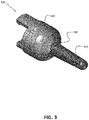
- FIG. 9 illustrates a second view of a portion of the mock welding tool 800 of FIG. 8 .
- the mock welding tool 800 includes a handle 810 configured to be held by a student welder.
- the mock welding tool 800 also includes a trigger 820 operatively connected to the handle 810 and configured to indicate an active weld state to a welding simulator.
- an electrical signal is sent from the mock welding tool 800 to a welding simulator, either wired or wirelessly, to activate a simulated (e.g., virtual reality) welding operation.
- a welding simulator will be discussed in more detail later herein.
- the handle 810 and the trigger 820 may be configured for a right-handed student welder in one embodiment, and for a left-handed student welder in another embodiment.
- the mock welding tool 800 also includes a mock stick electrode 830 having a spring-loaded tip assembly 100 or 700 attached to a portion thereof.
- the tip assembly 100 or 700 is as previously described herein, in accordance with various embodiments, and attaches (and is removable) via the attachable portion 600 of the tip assembly 100 or 700 (e.g., also see FIG. 6 and FIG. 7 ).
- the attachable portion 600 is configured to clip or snap onto the mock welding tool 800, in accordance with one embodiment. In other embodiments, the attachable portion may be configured to twist onto or slide and lock onto the mock welding tool. Other attachable embodiments are possible as well.
- the tip assembly 100 or 700 is configured as an adapter that connects to the mock welding tool 800.
- the mock welding tool 800 may also support the attachment of other adapter tool configurations for simulation of other types of welding or cutting, for example.
- the mock welding tool 800 includes an actuator assembly 840 configured to retract or withdraw the mock stick electrode 830 toward the student welder in response to the student welder activating (e.g., pressing or pulling) the trigger 820.
- the retracting or withdrawing of the mock stick electrode 830 simulates consumption of a real stick electrode during a SMAW operation.
- the actuator assembly 840 includes an electric motor.
- the mock welding tool 800 includes at least one sensor 850 to aid a welding simulator in tracking the mock welding tool 800 in at least position and orientation in three-dimensional space.
- the sensor and tracking technology may include one or more of, for example, accelerometers, gyros, magnets, conductive coils, lasers, ultrasonics, radio frequency devices, and scanning systems, in accordance with certain embodiments.
- An example of a welding simulator with spatial tracking capability is discussed in U.S. Patent No. 8,915,740 which is incorporated herein by reference in its entirety.
- the mock welding tool 800 includes a communication module 860 configured to communicate with a welding simulator. Communication between the mock welding tool 800 and the welding simulator may take place either wirelessly (e.g., via radio frequency or infrared) or via wired means (e.g., via an electrical cable), in accordance with various embodiments.
- the communication module 860 may facilitate communication of the electrical signal, produced when the trigger 820 is activated, from the mock welding tool 800 to the welding simulator.
- the communication module 860 may also facilitate communication of sensor signals produced by the sensor 850 (indicating position and orientation of the mock welding tool 800) from the mock welding tool 800 to the welding simulator.
- the communication module 860 may facilitate communication of warning and alert signals from the welding simulator to the mock welding tool 800.
- the mock welding tool 800 may include light emitting diodes (LEDs) and/or sound-producing transducers to warn and alert a welding student in response to the warning and alert signals.
- LEDs light emitting diodes
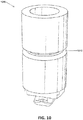
- FIG. 10 illustrates an embodiment of a pipe welding coupon 1000 used to support a simulated SMAW pipe welding operation.
- the pipe welding coupon 1000 includes a joint 1010 that circumscribes the coupon 1000.
- FIG. 11 illustrates one embodiment of the mock welding tool 800 of FIG. 8 and FIG. 9 in relation to the pipe welding coupon 1000 of FIG. 10 to simulate welding of the joint 1010 as part of a simulated SMAW pipe welding operation.
- the spring-loaded tip assembly of the mock welding tool 800 mitigates slippage at the welding coupon and provides a pressure-based tactile feedback to the student welder.
- FIG. 12 illustrates an example of a student welder 1100 using the mock welding tool 800 of FIG. 8 and FIG. 9 on the pipe welding coupon 1000 of Fig. 10 during a simulated SMAW operation as supported by a welding simulator 1200.
- the pipe welding coupon 1000 is supported by a welding stand 1110 which holds the pipe welding coupon in a desired position for the student welder 1100.
- the student welder 1100 is wearing a virtual reality welding helmet or face mounted display device (FMDD) 1120 which, along with the mock welding tool 800, communicatively interfaces to the welding simulator 1200.
- FMDD virtual reality welding helmet or face mounted display device
- the welding simulator 1200 provides an augmented reality and/or a virtual reality environment to the student welder which can be viewed by the student welder 1100 on display devices within the FMDD 1120 as the student welder 1100 uses the mock welding tool 800 to practice simulated SMAW pipe welding on the pipe welding coupon 1000.
- the spring-loaded tip assembly of the mock welding tool 800 provides a pressure-based tactile feedback to the student welder 1100 to simulate a feel of performing an actual shielded metal arc welding operation on a pipe as the electrode tip engages the pipe welding coupon 1000 during a simulated shielded metal arc welding operation.
- FIG. 13 illustrates a block diagram of an embodiment of a training welding system 1300 which includes the welding simulator 1200, the welding coupon 1000, the welding table/stand 1110, the FMDD 1120, and the mock welding tool 800 of FIG. 12 .
- the welding simulator 1200 includes a programmable processor-based subsystem (PPS) 1210, a spatial tracker (ST) 1220, a welding user interface (WUI) 1230, and an observer display device (ODD) 1240.
- PPS programmable processor-based subsystem
- ST spatial tracker
- WUI welding user interface
- ODD observer display device
- the signal generated by the pressure sensor transducer 710 to indicate the amount of compression of the compression spring 120 is representative of at least one simulated arc characteristic, in accordance with one embodiment.
- the simulated arc characteristic may be, for example, an arc voltage, an arc current, an arc length (arc distance), or an extinguished arc.
- the signal may be provided (wired or wirelessly) to the welding simulator 1200 which is configured to correlate the signal to at least one arc characteristic and generate a response based on the correlation.
- the signal may be an analog signal and/or a digital signal, in accordance with various embodiments.
- the signal may be correlated to an "arc extinguish” characteristic, indicating that the electrode tip 110 has been pushed too far into the joint 1010 of the pipe welding coupon 1000 and that, in the real world, the arc would have been extinguished as a result.
- the signal may be correlated to an "arc distance” characteristic, indicating that the arc distance is too short or too long and that the student welder should adjust the position of the mock welding tool 800 with respect to the joint 1010 in an attempt to achieve a proper arc distance.
- the welding simulator 1200 can provide various alerts and warnings to the student welder based on such arc characteristics, in accordance with one embodiment. Also, the welding simulator 1200 can apply a penalty to a score of a student welder when the student welder goes "out of bounds" with respect to various arc characteristics.
- FIG. 14 illustrates a flowchart of a first embodiment of a method 1400 to assemble a spring-loaded tip assembly 100.
- interface a first end of a compression spring with a proximal end of an elongate mock electrode tip having a locking sleeve near the proximal end.
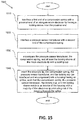
- FIG. 15 illustrates a flowchart of a second embodiment of a method 1500 to assemble a spring-loaded tip assembly 700.
- REFERENCE NUMERALS 100 tip assembly 1000 pipe welding coupon 110 mock electrode tip 1010 joint 112 proximal end 1100 student welder 114 distal end 1110 welding table/stand 116 locking sleeve 1120 face mounted display device (FMDD) 120 compression spring 122 first end 1200 welding simulator 124 second end 1210 processor-based subsystem (PPS) 130 locking cup 140 housing 1220 spatial tracker (ST) 142 orifice 1230 welding user interface (WUI) 400 locked configuration 1240 observer display device (ODD) 500 un-locked configuration 1300 training welding system 600 attachable portion 1400 method 700 tip assembly 1410 block 710 transducer 1420 block 800 mock welding tool 1430 block 810 handle 1500 method 820 trigger 1510 block 830 mock stick electrode 1520 block 840 actuator assembly 1530 block 850 sensor 1540 block 860 communication module
Abstract
Description
- This U.S. patent application claims priority to and the benefit of
U.S. provisional patent application serial number 62/513,584 filed on June 1, 2017 U.S. Patent No. 8,915,740 entitled "Virtual Reality Pipe Welding Simulator", filed on July 10, 2009 and issued on December 23, 2014, is incorporated herein by reference in its entirety. - The invention relates to a tip assembly, to a mock welding tool having a tip assembly, and to a method of assembling a tip assembly, according to the preamble of claims 1, 12 and 15, respectively. Embodiments of the present invention thus relate to systems, apparatus, and methods associated with simulated welding. More specifically, embodiments of the present invention relate to systems, apparatus, and methods to support simulation of a shielded metal arc welding (SMAW) operation via a spring-loaded tip assembly.
- In certain weld joints (e.g., SMAW pipe welding), the process of welding requires the user to feel the welding joint of the workpiece via the electrode being used. There is an ideal pressure that is to be applied to the weld joint to find the proper arc distance. Current professional welders feed the electrode into the joint beyond first contact to obtain proper arc length and weld deposition rate. Simulating a SMAW pipe welding process for training welding students can be difficult. With today's simulated/virtual welding training systems, an artificial electrode tip provided as part of a mock SMAW tool tends to be rigid. This results in an unrealistic simulation of the SMAW operation. For example, electrode slippage can occur at the welding coupon, there is an absence of a pressure-based welding technique, and there is a lack of proper disposition. A way to more realistically simulate a SMAW pipe welding process is desired.
- Embodiments of the present invention include spring-loaded tip assemblies to support simulation of a shielded metal arc welding (SMAW) operation for training student welders. The spring-loaded tip assemblies include an elongate mock electrode tip that mitigates slippage at the welding coupon and provides a pressure-based tactile feedback to the student welder.
- One embodiment includes a tip assembly to support simulation of a shielded metal arc welding (SMAW) operation. The tip assembly includes an elongate mock electrode tip having a proximal end, a distal end, and a locking sleeve near the proximal end. The tip assembly also includes a compression spring having a first end and a second end. The first end is configured to interface with the proximal end of the electrode tip. The tip assembly further includes a locking cup configured to encompass the compression spring and the locking sleeve of the electrode tip. The tip assembly also includes a housing having an orifice. The housing is configured to receive the electrode tip, the compression spring, and the locking cup into the housing by accepting the distal end of the electrode tip through the orifice of the housing up to the locking sleeve. The result is that the compression spring, the locking cup, and the locking sleeve reside in an interior of the housing with a majority of the electrode tip protruding out of the housing. The locking sleeve and the locking cup are configured to be rotated with respect to each other to allow changing between a locked position and an unlocked position. In one embodiment, the locked position holds the compression spring in a fully compressed state within the locking cup while holding the electrode tip in an immovable state with respect to the locking cup and the housing, for use in simulated shielded metal arc welding of a plate welding coupon. The unlocked position puts the compression spring in a free state. The free state allows the compression spring to compress as the distal end of the electrode tip is pushed toward the housing. The free state also allows the compression spring to decompress to push the distal end of the electrode tip away from the housing. The result is that a tactile feedback is provided to a student welder to simulate a feel of performing an actual shielded metal arc welding operation on a pipe as the electrode tip engages a pipe welding coupon during a simulated shielded metal arc welding operation. In one embodiment, the housing is configured to removably attach to a mock welding tool for use in a SMAW operation. In one embodiment, the distal end of the electrode tip is made of a material configured to mitigate slippage between the electrode tip and a welding coupon during a simulated SMAW operation. For example, at least a portion of the electrode tip may be made of polyoxymethylene. In one embodiment, at least a portion of the compression spring is made of polyetherimide.
- One embodiment includes a tip assembly to support simulation of a shielded metal arc welding operation. The tip assembly includes an elongate mock electrode tip having a proximal end, a distal end, and a sleeve near the proximal end. The tip assembly also includes a compression spring having a first end and a second end. The first end is configured to interface with the proximal end of the electrode tip. The tip assembly further includes a pressure sensor transducer configured to interface with the second end of the compression spring to sense an amount of compression of the compression spring and to generate a signal indicating the amount of compression of the compression spring. The tip assembly also includes a cup configured to encompass the pressure sensor transducer, the compression spring, and the sleeve of the electrode tip. The tip assembly further includes a housing having an orifice. The housing is configured to receive the electrode tip, the compression spring, the pressure sensor transducer, and the cup into the housing by accepting the distal end of the electrode tip through the orifice of the housing up to the sleeve. The result is that the pressure sensor transducer, the compression spring, the cup, and the sleeve reside in an interior of the housing with a majority of the electrode tip protruding out of the housing. In one embodiment, the signal indicating the amount of compression of the compression spring is representative of at least one simulated arc characteristic. The simulated arc characteristic may include, for example, an arc voltage, an arc current, an arc length, or an extinguished arc. In one embodiment, the sleeve and the cup are configured to be rotated with respect to each other to allow changing between a locked position and an unlocked position. In one embodiment, the locked position holds the compression spring in a fully compressed state within the locking cup while holding the electrode tip in an immovable state with respect to the locking cup and the housing, for use in simulated shielded metal arc welding of a plate welding coupon. The unlocked position puts the compression spring in a free state. The free state allows the compression spring to compress as the distal end of the electrode tip is pushed toward the housing. The free state also allows the compression spring to decompress to push the distal end of the electrode tip away from the housing. The result is that a tactile feedback is provided to a student welder to simulate a feel of performing an actual shielded metal arc welding operation on a pipe as the electrode tip engages a pipe welding coupon during a simulated shielded metal arc welding operation.
- One embodiment includes a mock welding tool to support simulation of a SMAW operation. The mock welding tool includes a handle configured to be held by a student welder and a trigger operatively connected to the handle and configured to indicate an active weld state to a welding simulator. The mock welding tool also includes a mock stick electrode having a tip assembly. The tip assembly includes an elongate mock electrode tip having a proximal end, a distal end, and a locking sleeve near the proximal end. The tip assembly also includes a compression spring having a first end and a second end. The first end is configured to interface with the proximal end of the electrode tip. The tip assembly further includes a locking cup configured to encompass the compression spring and the locking sleeve of the electrode tip. The tip assembly also includes a housing having an orifice. The housing is configured to receive the electrode tip, the compression spring, and the locking cup into the housing by accepting the distal end of the electrode tip through the orifice of the housing up to the locking sleeve. The result is that the compression spring, the locking cup, and the locking sleeve reside in an interior of the housing with a majority of the electrode tip protruding out of the housing. The locking sleeve and the locking cup are configured to be rotated with respect to each other to allow changing between a locked position and an unlocked position. In one embodiment, the locked position holds the compression spring in a fully compressed state within the locking cup while holding the electrode tip in an immovable state with respect to the locking cup and the housing, for use in simulated shielded metal arc welding of a plate welding coupon. The unlocked position puts the compression spring in a free state. The free state allows the compression spring to compress as the distal end of the electrode tip is pushed toward the housing. The free state also allows the compression spring to decompress to push the distal end of the electrode tip away from the housing. The result is that a tactile feedback is provided to a student welder to simulate a feel of performing an actual shielded metal arc welding operation on a pipe as the electrode tip engages a pipe welding coupon during a simulated shielded metal arc welding operation. In one embodiment, the mock welding tool includes at least one sensor to aid the welding simulator in tracking the mock welding tool in at least position and orientation in three-dimensional space. In one embodiment, the mock welding tool includes an actuator assembly configured to retract the mock stick electrode toward the student welder, in response to the student welder activating the trigger, to simulate consumption of a real stick electrode. In one embodiment, the mock welding tool includes a communication module configured to communicate with the welding simulator. Communication may be wireless or via a cable connected between the mock welding tool and the welding simulator.
- Numerous aspects of the general inventive concepts will become readily apparent from the following detailed description of exemplary embodiments, from the claims, and from the accompanying drawings.
- The accompanying drawings, which are incorporated in and constitute a part of the specification, illustrate various embodiments of the disclosure. It will be appreciated that the illustrated element boundaries (e.g., boxes, groups of boxes, or other shapes) in the figures represent one embodiment of boundaries. In some embodiments, one element may be designed as multiple elements or that multiple elements may be designed as one element. In some embodiments, an element shown as an internal component of another element may be implemented as an external component and vice versa. Furthermore, elements may not be drawn to scale.
-
FIG. 1 illustrates an exploded view of a first embodiment of a spring-loaded tip assembly to support a simulated SMAW operation; -
FIG. 2 illustrates a first assembled view of the embodiment ofFIG. 1 ; -
FIG. 3 illustrates a second assembled view of the embodiment ofFIG. 1 ; -
FIG. 4 illustrates a locked configuration of a portion of an assembled embodiment of the spring-loaded tip assembly ofFIG. 1 to FIG. 3 ; -
FIG. 5 illustrates an un-locked configuration of a portion of an assembled embodiment of the spring-loaded tip assembly ofFIG. 1 to FIG. 3 ; -
FIG. 6 illustrates a cross-sectional view of the assembled embodiment of the spring-loaded tip assembly ofFIG. 1 to FIG. 3 ; -
FIG. 7 illustrates an exploded view of a second embodiment of a spring-loaded tip assembly to support a simulated SMAW operation; -
FIG. 8 illustrates a first view of an embodiment of a mock welding tool having the spring-loaded tip assembly ofFIG. 1 to FIG. 3 ; -
FIG. 9 illustrates a second view of the mock welding tool ofFIG. 8 ; -
FIG. 10 illustrates an embodiment of a pipe welding coupon used to support a simulated SMAW operation; -
FIG. 11 illustrates one embodiment of the mock welding tool ofFIG. 8 andFIG. 9 in relation to the pipe welding coupon ofFIG. 10 ; -
FIG. 12 illustrates an example of a student welder using the mock welding tool ofFIG. 8 andFIG. 9 on the pipe welding coupon ofFig. 10 during a simulated SMAW operation as supported by a welding simulator; -
FIG. 13 illustrates a block diagram of an embodiment of a training welding system having the welding simulator ofFIG. 12 ; -
FIG. 14 illustrates a flowchart of a first embodiment of a method to assemble a spring-loaded tip assembly; and -
FIG. 15 illustrates a flowchart of a second embodiment of a method to assemble a spring-loaded tip assembly. - Embodiments of systems, apparatus, and methods to support simulation of a shielded metal arc welding (SMAW) operation via a spring-loaded tip assembly are disclosed. In one embodiment, a welding simulator is provided which includes a mock welding tool having a tip assembly. The tip assembly includes an elongate mock electrode tip having a proximal end, a distal end, and a locking sleeve near the proximal end. A compression spring is configured to interface with the proximal end of the electrode tip. A locking cup is configured to encompass the compression spring and the locking sleeve. A housing, having an orifice, is configured to receive the electrode tip, the compression spring, and the locking cup into an interior of the housing by accepting the distal end of the electrode tip through the orifice up to the locking sleeve. The locking sleeve and the locking cup are configured to be rotated with respect to each other to allow changing between a locked position and an unlocked position.
- The examples and figures herein are illustrative only and are not meant to limit the subject invention, which is measured by the scope and spirit of the claims. Referring now to the drawings, wherein the showings are for the purpose of illustrating exemplary embodiments of the subject invention only and not for the purpose of limiting same,
FIG. 1 illustrates an exploded view of a first embodiment of a spring-loadedtip assembly 100 to support a simulated SMAW operation. - Referring to
FIG. 1 , thetip assembly 100 includes an elongatemock electrode tip 110. Theelectrode tip 110 has aproximal end 112, adistal end 114, and a lockingsleeve 116 near theproximal end 112. Thetip assembly 100 also includes acompression spring 120 having afirst end 122 and a second end 124. Thefirst end 122 is configured to interface with theproximal end 112 of theelectrode tip 110. For example, as shown inFIG. 1 , a male/female type of interface is provided. Thetip assembly 100 includes a lockingcup 130 configured to encompass thecompression spring 120 and the lockingsleeve 116 of theelectrode tip 110. - The
tip assembly 100 includes ahousing 140 having anorifice 142. Thehousing 140 is configured to receive theelectrode tip 110, thecompression spring 120, and the lockingcup 130 into an interior of thehousing 140 by accepting thedistal end 114 of theelectrode tip 110 through theorifice 142 up to the lockingsleeve 116. With theelectrode tip 110, thecompression spring 120, and the lockingcup 130 assembled within the interior of thehousing 140, the majority of theelectrode tip 110 protrudes from thehousing 140 out of theorifice 142, as shown inFIG. 2 andFIG. 3 .FIG. 2 illustrates a first assembled view of the embodiment ofFIG. 1 andFIG. 3 illustrates a second assembled view of the embodiment ofFIG. 1 . - In accordance with one embodiment, the locking
sleeve 116 and the lockingcup 130 are configured to be rotated with respect to each other to allow changing between a locked position and an unlocked position.FIG. 4 illustrates a lockedconfiguration 400 of a portion of an assembled embodiment of the spring-loadedtip assembly 100 ofFIG. 1 to FIG. 3 , showing theelectrode tip 110 and the lockingcup 130 in a locked position.FIG. 5 illustrates anun-locked configuration 500 of a portion of an assembled embodiment of the spring-loadedtip assembly 100 ofFIG. 1 to FIG. 3 , showing theelectrode tip 110 and the lockingcup 130 in an unlocked position. - In
FIG. 4 , thecompression spring 120 is in the locked position and is not seen inFIG. 4 because it is compressed and entirely encompassed by the lockingcup 130 and the lockingsleeve 116. In one embodiment, thecompression spring 120 is in a fully compressed state in the locked position and theelectrode tip 110 is in an immovable state (is locked) with respect to the lockingcup 130 and thehousing 140. To accomplish the locked position, in one embodiment, a user would push theelectrode tip 110 into thehousing 140 as far as theelectrode tip 110 will go, and then rotate theelectrode tip 110 with respect to the lockingcup 130. As can be seen inFIG. 4 , a portion of the lockingsleeve 116 engages with a slot of the lockingcup 130 to put thetip assembly 100 in the locked position. Other equivalent locking configurations are possible as well, in accordance with other embodiments. In this manner, the locking position is provided to support a simulated SMAW plate welding operation. - In
FIG. 5 , thecompression spring 120 is in the unlocked position which puts thecompression spring 120 in a free state. As can be seen inFig. 5 , the lockingsleeve 116 is no longer engaged with the slot of the lockingcup 130. The free state allows thecompression spring 120 to compress as thedistal end 114 of theelectrode tip 110 is pushed toward the housing 140 (e.g., as a student welder pushes thedistal end 114 of theelectrode tip 110 into the joint of a pipe welding coupon during a simulated SMAW pipe welding operation via a mock welding tool having thetip assembly 100 attached thereto). The free state also allows thecompression spring 120 to decompress to push thedistal end 114 of theelectrode tip 110 away from the housing 140 (e.g. as the student welder pulls the mock welding tool, having thetip assembly 100 attached thereto, away from the joint of the pipe welding coupon during the simulated SMAW pipe welding operation). In this manner, a tactile feedback is provided to the student welder to simulate a feel of performing an actual SMAW operation on a pipe as theelectrode tip 110 engages the pipe welding coupon during the simulated SMAW operation. -
FIG. 6 illustrates a cross-sectional view of the assembled embodiment of the spring-loadedtip assembly 100 ofFIG. 1 to FIG. 3 . As seen inFIG. 6 , thehousing 140 includes anattachable portion 600 which allows thetip assembly 100 to be attached to and removed from a mock welding tool as discussed later herein. Theattachable portion 600 ofFIG. 6 is in the form of a clip-on or snap-on configuration. Other equivalent attachable portion configurations are possible as well, in accordance with other embodiments. - The
electrode tip 110 is made of a material configured to mitigate slippage between theelectrode tip 110 and a welding coupon during a simulated SMAW operation. For example, in one embodiment, at least thedistal end 114 of theelectrode tip 110 is made of a polyoxymethylene material. The polyoxymethylene material mitigates slippage as desired. In accordance with one embodiment, at least a portion of thecompression spring 120 is made of a polyetherimide material. The polyetherimide material provides desired compression spring characteristics for applications to simulated SMAW operations. Other equivalent materials may be possible as well, in accordance with other embodiments. -
FIG. 7 illustrates an exploded view of a second embodiment of a spring-loadedtip assembly 700 to support a simulated SMAW operation. Thetip assembly 700 ofFIG. 7 is similar to thetip assembly 100 of the previous figures except that thetip assembly 700 further includes apressure sensor transducer 710. Thepressure sensor transducer 710 is configured to interface with thesecond end 121 of thecompression spring 120 to sense an amount of compression of thecompression spring 120 and to generate a signal indicating the amount of compression of thecompression spring 120. In accordance with one embodiment, thepressure sensor transducer 710 uses piezoelectric technology. In other embodiments, thepressure sensor transducer 710 may use other types of sensor and transducer technology. Thecup 130 is configured to encompass thepressure sensor transducer 710, thecompression spring 120, and thesleeve 116 of theelectrode tip 110. Thehousing 140 is configured to receive theelectrode tip 110, thecompression spring 120, thepressure sensor transducer 710, and thecup 130 into an interior of the housing in a similar manner to that ofFIG. 1 to Fig. 3 . - In one embodiment, the
cup 130 and thesleeve 116 of thetip assembly 700 are a locking cup and a locking sleeve similar to that ofFIG. 1 to FIG. 3 . However, in an alternative embodiment, thecup 130 and thesleeve 116 of thetip assembly 700 do not provide the ability to change between a locked position and an unlocked position as described previously herein. Instead, theelectrode tip 110 is always unlocked and in the free state (described previously herein) to support a simulated SMAW pipe welding operation. - The signal generated by the
pressure sensor transducer 710 to indicate the amount of compression of thecompression spring 120 is representative of at least one simulated arc characteristic, in accordance with one embodiment. The simulated arc characteristic may be an arc voltage, an arc current, an arc length (arc distance), or an extinguished arc. The signal may be provided (wired or wirelessly) to a welding simulator which is configured to correlate the signal to at least one arc characteristic and generate a response based on the correlation as discussed later herein. The signal may be an analog signal and/or a digital signal, in accordance with various embodiments. -
FIG. 8 illustrates a first view of an embodiment of amock welding tool 800 having the spring-loadedtip assembly 100 ofFIG. 1 or the spring-loadedtip assembly 700 ofFIG. 7 .FIG. 9 illustrates a second view of a portion of themock welding tool 800 ofFIG. 8 . Themock welding tool 800 includes ahandle 810 configured to be held by a student welder. Themock welding tool 800 also includes atrigger 820 operatively connected to thehandle 810 and configured to indicate an active weld state to a welding simulator. For example, in one embodiment, when a student welder presses thetrigger 820, an electrical signal is sent from themock welding tool 800 to a welding simulator, either wired or wirelessly, to activate a simulated (e.g., virtual reality) welding operation. A welding simulator will be discussed in more detail later herein. Thehandle 810 and thetrigger 820 may be configured for a right-handed student welder in one embodiment, and for a left-handed student welder in another embodiment. - The
mock welding tool 800 also includes amock stick electrode 830 having a spring-loadedtip assembly tip assembly attachable portion 600 of thetip assembly 100 or 700 (e.g., also seeFIG. 6 andFIG. 7 ). Theattachable portion 600 is configured to clip or snap onto themock welding tool 800, in accordance with one embodiment. In other embodiments, the attachable portion may be configured to twist onto or slide and lock onto the mock welding tool. Other attachable embodiments are possible as well. Furthermore, in one embodiment, thetip assembly mock welding tool 800. Themock welding tool 800 may also support the attachment of other adapter tool configurations for simulation of other types of welding or cutting, for example. - The
mock welding tool 800 includes anactuator assembly 840 configured to retract or withdraw themock stick electrode 830 toward the student welder in response to the student welder activating (e.g., pressing or pulling) thetrigger 820. The retracting or withdrawing of themock stick electrode 830 simulates consumption of a real stick electrode during a SMAW operation. In accordance with one embodiment, theactuator assembly 840 includes an electric motor. - In one embodiment, the
mock welding tool 800 includes at least onesensor 850 to aid a welding simulator in tracking themock welding tool 800 in at least position and orientation in three-dimensional space. The sensor and tracking technology may include one or more of, for example, accelerometers, gyros, magnets, conductive coils, lasers, ultrasonics, radio frequency devices, and scanning systems, in accordance with certain embodiments. An example of a welding simulator with spatial tracking capability is discussed inU.S. Patent No. 8,915,740 which is incorporated herein by reference in its entirety. - In one embodiment, the
mock welding tool 800 includes acommunication module 860 configured to communicate with a welding simulator. Communication between themock welding tool 800 and the welding simulator may take place either wirelessly (e.g., via radio frequency or infrared) or via wired means (e.g., via an electrical cable), in accordance with various embodiments. Thecommunication module 860 may facilitate communication of the electrical signal, produced when thetrigger 820 is activated, from themock welding tool 800 to the welding simulator. Thecommunication module 860 may also facilitate communication of sensor signals produced by the sensor 850 (indicating position and orientation of the mock welding tool 800) from themock welding tool 800 to the welding simulator. In one embodiment, thecommunication module 860 may facilitate communication of warning and alert signals from the welding simulator to themock welding tool 800. For example, themock welding tool 800 may include light emitting diodes (LEDs) and/or sound-producing transducers to warn and alert a welding student in response to the warning and alert signals. -
FIG. 10 illustrates an embodiment of apipe welding coupon 1000 used to support a simulated SMAW pipe welding operation. Thepipe welding coupon 1000 includes a joint 1010 that circumscribes thecoupon 1000.FIG. 11 illustrates one embodiment of themock welding tool 800 ofFIG. 8 andFIG. 9 in relation to thepipe welding coupon 1000 ofFIG. 10 to simulate welding of the joint 1010 as part of a simulated SMAW pipe welding operation. The spring-loaded tip assembly of themock welding tool 800 mitigates slippage at the welding coupon and provides a pressure-based tactile feedback to the student welder. -
FIG. 12 illustrates an example of astudent welder 1100 using themock welding tool 800 ofFIG. 8 andFIG. 9 on thepipe welding coupon 1000 ofFig. 10 during a simulated SMAW operation as supported by awelding simulator 1200. As shown inFIG. 12 , thepipe welding coupon 1000 is supported by awelding stand 1110 which holds the pipe welding coupon in a desired position for thestudent welder 1100. InFIG. 12 , thestudent welder 1100 is wearing a virtual reality welding helmet or face mounted display device (FMDD) 1120 which, along with themock welding tool 800, communicatively interfaces to thewelding simulator 1200. In certain embodiments, thewelding simulator 1200 provides an augmented reality and/or a virtual reality environment to the student welder which can be viewed by thestudent welder 1100 on display devices within theFMDD 1120 as thestudent welder 1100 uses themock welding tool 800 to practice simulated SMAW pipe welding on thepipe welding coupon 1000. Again, the spring-loaded tip assembly of themock welding tool 800 provides a pressure-based tactile feedback to thestudent welder 1100 to simulate a feel of performing an actual shielded metal arc welding operation on a pipe as the electrode tip engages thepipe welding coupon 1000 during a simulated shielded metal arc welding operation. -
FIG. 13 illustrates a block diagram of an embodiment of atraining welding system 1300 which includes thewelding simulator 1200, thewelding coupon 1000, the welding table/stand 1110, theFMDD 1120, and themock welding tool 800 ofFIG. 12 . Thewelding simulator 1200 includes a programmable processor-based subsystem (PPS) 1210, a spatial tracker (ST) 1220, a welding user interface (WUI) 1230, and an observer display device (ODD) 1240. A detailed description of embodiments of thePPS 1210, theST 1220, theWUI 1230, the ODD 1240 (as well as theFMDD 1120, thewelding coupon 1000, and the welding table/stand 1110) can be found inU.S. Patent No. 8,915,740 which is incorporated herein by reference in its entirety. It is noted that reference numerals that are different from those used herein may be used inU.S. Patent No. 8,915,740 for the corresponding components. - As discussed previously herein, the signal generated by the
pressure sensor transducer 710 to indicate the amount of compression of thecompression spring 120 is representative of at least one simulated arc characteristic, in accordance with one embodiment. The simulated arc characteristic may be, for example, an arc voltage, an arc current, an arc length (arc distance), or an extinguished arc. The signal may be provided (wired or wirelessly) to thewelding simulator 1200 which is configured to correlate the signal to at least one arc characteristic and generate a response based on the correlation. The signal may be an analog signal and/or a digital signal, in accordance with various embodiments. - For example, the signal may be correlated to an "arc extinguish" characteristic, indicating that the
electrode tip 110 has been pushed too far into the joint 1010 of thepipe welding coupon 1000 and that, in the real world, the arc would have been extinguished as a result. As another example, the signal may be correlated to an "arc distance" characteristic, indicating that the arc distance is too short or too long and that the student welder should adjust the position of themock welding tool 800 with respect to the joint 1010 in an attempt to achieve a proper arc distance. Thewelding simulator 1200 can provide various alerts and warnings to the student welder based on such arc characteristics, in accordance with one embodiment. Also, thewelding simulator 1200 can apply a penalty to a score of a student welder when the student welder goes "out of bounds" with respect to various arc characteristics. -
FIG. 14 illustrates a flowchart of a first embodiment of amethod 1400 to assemble a spring-loadedtip assembly 100. Atblock 1410 ofFIG. 14 , interface a first end of a compression spring with a proximal end of an elongate mock electrode tip having a locking sleeve near the proximal end. Atblock 1420, encompass the compression spring and at least the locking sleeve of the mock electrode tip with a locking cup. Atblock 1430, insert the electrode tip, the compression spring, and the locking cup (as interfaced and encompassed) into a housing having an orifice such that the compression spring, the locking cup, and the locking sleeve reside in an interior of the housing with a majority of the mock electrode tip protruding out of the housing through the orifice. The blocks 1410-1430 may be performed in the order given or in an alternate order which results in the same final assembled configuration of the spring-loadedtip assembly 100. -
FIG. 15 illustrates a flowchart of a second embodiment of amethod 1500 to assemble a spring-loadedtip assembly 700. Atblock 1510, interface a first end of a compression spring with a proximal end of an elongate mock electrode tip having a locking sleeve near the proximal end. Atblock 1520, interface a pressure sensor transducer with a second end of the compression spring. Atblock 1530, encompass the pressure sensor transducer, the compression spring, and at least the locking sleeve of the mock electrode tip with a locking cup. Atblock 1540, insert the electrode tip, the compression spring, the pressure sensor transducer, and the locking cup (as interfaced and encompassed) into a housing having an orifice such the compression spring, the pressure sensor transducer, the locking cup, and the locking sleeve reside in an interior of the housing with a majority of the electrode tip protruding out of the housing through the orifice. The blocks 1510-1540 may be performed in the order given or in an alternate order which results in the same final assembled configuration of the spring-loadedtip assembly 700. - While the disclosed embodiments have been illustrated and described in considerable detail, it is not the intention to restrict or in any way limit the scope of the appended claims to such detail. It is, of course, not possible to describe every conceivable combination of components or methodologies for purposes of describing the various aspects of the subject matter. Therefore, the disclosure is not limited to the specific details or illustrative examples shown and described. Thus, this disclosure is intended to embrace alterations, modifications, and variations that fall within the scope of the appended claims, which satisfy the statutory subject matter requirements of 35 U.S.C. §101. The above description of specific embodiments has been given by way of example. From the disclosure given, those skilled in the art will not only understand the general inventive concepts and attendant advantages, but will also find apparent various changes and modifications to the structures and methods disclosed. It is sought, therefore, to cover all such changes and modifications as fall within the spirit and scope of the general inventive concepts, as defined by the appended claims, and equivalents thereof.
REFERENCE NUMERALS 100 tip assembly 1000 pipe welding coupon 110 mock electrode tip 1010 joint 112 proximal end 1100 student welder 114 distal end 1110 welding table/stand 116 locking sleeve 1120 face mounted display device (FMDD) 120 compression spring 122 first end 1200 welding simulator 124 second end 1210 processor-based subsystem (PPS) 130 locking cup 140 housing 1220 spatial tracker (ST) 142 orifice 1230 welding user interface (WUI) 400 locked configuration 1240 observer display device (ODD) 500 un-locked configuration 1300 training welding system 600 attachable portion 1400 method 700 tip assembly 1410 block 710 transducer 1420 block 800 mock welding tool 1430 block 810 handle 1500 method 820 trigger 1510 block 830 mock stick electrode 1520 block 840 actuator assembly 1530 block 850 sensor 1540 block 860 communication module
Claims (15)
- A tip assembly (100) to support simulation of a shielded metal arc welding operation, the tip assembly (100) comprising:an elongate mock electrode tip (110) having a proximal end (112), a distal end (114), and a locking sleeve (116) near the proximal end;characterized bya compression spring (120) having a first end (122) and a second end (124), wherein the first end (122) is configured to interface with the proximal end (112) of the electrode tip (110);a locking cup (130) configured to encompass the compression spring (120) and the locking sleeve (116) of the electrode tip (110); anda housing (140) having an orifice (142), wherein the housing (140) is configured to receive the electrode tip (110), the compression spring (120), and the locking cup (130) into the housing (140) by accepting the distal end (114) of the electrode tip (110) through the orifice (142) of the housing (140) up to the locking sleeve 116), resulting in the compression spring (120), the locking cup (130), and the locking sleeve (116) residing in an interior of the housing (140) with a majority of the electrode tip (110)protruding out of the housing (140), andwherein the locking sleeve (116) and the locking cup (130) are configured to be rotated with respect to each other to allow changing between a locked position (400) and an unlocked position (500).
- The tip assembly of claim 1, wherein the locked position holds the compression spring in a fully compressed state within the locking cup while holding the electrode tip in an immovable state with respect to the locking cup and the housing, for use in simulated shielded metal arc welding of a plate welding coupon.
- The tip assembly of claim 1 or 2, wherein the unlocked position puts the compression spring in a free state, allowing the compression spring to compress as the distal end of the electrode tip is pushed toward the housing, and allowing the compression spring to decompress to push the distal end of the electrode tip away from the housing, resulting in providing a tactile feedback to a student welder to simulate a feel of performing an actual shielded metal arc welding operation on a pipe as the electrode tip engages a pipe welding coupon during a simulated shielded metal arc welding operation.
- The tip assembly of one of the claims 1 to 3, wherein the housing is configured to removably attach to a mock welding tool for use in a simulated shielded metal arc welding operation.
- The tip assembly of one of the claim 1 to 4, wherein at least the distal end of the electrode tip is made of a material configured to mitigate slippage between the electrode tip and a welding coupon during a simulated shielded metal arc welding operation.
- The tip assembly of one of the claims 1 to 5, wherein at least a portion of the compression spring is made of polyetherimide; and/or wherein at least a portion of the electrode tip is made of polyoxymethylene.
- A tip assembly to support simulation of a shielded metal arc welding operation, in particular according to one of the preceding claims, the tip assembly comprising:an elongate mock electrode tip having a proximal end, a distal end, and a sleeve near the proximal end;characterized bya compression spring having a first end and a second end, wherein the first end is configured to interface with the proximal end of the electrode tip;a pressure sensor transducer (710) configured to interface with the second end of the compression spring to sense an amount of compression of the compression spring and to generate a signal indicating the amount of compression of the compression spring;a cup configured to encompass the pressure sensor transducer (710), the compression spring, and the sleeve of the electrode tip; anda housing having an orifice, wherein the housing is configured to receive the electrode tip, the compression spring, the pressure sensor transducer (710), and the cup into the housing by accepting the distal end of the electrode tip through the orifice of the housing up to the sleeve, resulting in the pressure sensor transducer (710), the compression spring, the cup, and the sleeve residing in an interior of the housing with a majority of the electrode tip protruding out of the housing.
- The tip assembly of claim 7, wherein the signal indicating the amount of compression of the compression spring is representative of at least one simulated arc characteristic.
- The tip assembly of claim 8, wherein the at least one simulated arc characteristic includes at least one of an arc voltage, an arc current, an arc length, and an extinguished arc.
- The tip assembly of one of the claims 7 to 9, wherein the sleeve and the cup are configured to be rotated with respect to each other to allow changing between a locked position and an unlocked position.
- The tip assembly of claim 10, wherein the locked position holds the compression spring in a fully compressed state within the cup while holding the electrode tip in an immovable state with respect to the cup and the housing, for use during a simulated shielded metal arc welding operation on a plate welding coupon; and/or wherein the unlocked position puts the compression spring in a free state, allowing the compression spring to compress as the distal end of the electrode tip is pushed toward the housing, and allowing the compression spring to decompress to push the distal end of the electrode tip away from the housing, resulting in providing a tactile feedback to a student welder to simulate a feel of performing an actual shielded metal arc welding operation on a pipe as the electrode tip engages a pipe welding coupon during a simulated shielded metal arc welding operation.
- A mock welding tool (800) to support simulation of a shielded metal arc welding operation, the mock welding tool (800) comprising:a handle (810) configured to be held by a student welder (1100);a trigger (820) operatively connected to the handle (810) and configured to indicate an active weld state to a welding simulator;characterized by
a mock stick electrode (830) having a tip assembly (100), according to one of the preceding claims. - The mock welding tool of claim 12, further comprising at least one sensor to aid the welding simulator in tracking the mock welding tool in at least position and orientation in three-dimensional space; and/or further comprising an actuator assembly configured to retract the mock stick electrode toward the student welder, in response to the student welder activating the trigger, to simulate consumption of a real stick electrode.
- The mock welding tool of one of the claims 12 or 13, further comprising a communication module configured to wirelessly communicate with the welding simulator; and/or further comprising a communication module configured to communicate with the welding simulator via a cable connected between the mock welding tool and the welding simulator.
- Method of assembling spring loaded tip assembly according to one of the preceding claims, characterized by the steps of Fig. 14 or Fig. 15.
Applications Claiming Priority (2)
| Application Number | Priority Date | Filing Date | Title |
|---|---|---|---|
| US201762513584P | 2017-06-01 | 2017-06-01 | |
| US15/696,495 US10997872B2 (en) | 2017-06-01 | 2017-09-06 | Spring-loaded tip assembly to support simulated shielded metal arc welding |
Publications (3)
| Publication Number | Publication Date |
|---|---|
| EP3431215A2 true EP3431215A2 (en) | 2019-01-23 |
| EP3431215A3 EP3431215A3 (en) | 2019-04-10 |
| EP3431215B1 EP3431215B1 (en) | 2020-09-09 |
Family
ID=64459902
Family Applications (1)
| Application Number | Title | Priority Date | Filing Date |
|---|---|---|---|
| EP18175115.7A Active EP3431215B1 (en) | 2017-06-01 | 2018-05-30 | Tip assembly to support simulated shielded metal arc welding with a spring-loaded lockable elongated electrode tip |
Country Status (7)
| Country | Link |
|---|---|
| US (1) | US10997872B2 (en) |
| EP (1) | EP3431215B1 (en) |
| JP (1) | JP7041006B2 (en) |
| KR (1) | KR20180131974A (en) |
| CN (1) | CN108971715B (en) |
| BR (1) | BR102018011095A2 (en) |
| ES (1) | ES2827550T3 (en) |
Citations (1)
| Publication number | Priority date | Publication date | Assignee | Title |
|---|---|---|---|---|
| US8915740B2 (en) | 2008-08-21 | 2014-12-23 | Lincoln Global, Inc. | Virtual reality pipe welding simulator |
Family Cites Families (404)
| Publication number | Priority date | Publication date | Assignee | Title |
|---|---|---|---|---|
| US317063A (en) | 1885-05-05 | wittenstrom | ||
| US428459A (en) | 1890-05-20 | Process of welding metals electrically | ||
| US483428A (en) | 1892-09-27 | Process of electric metal-working | ||
| US1159119A (en) | 1915-04-21 | 1915-11-02 | Charles Springer | Welding-torch. |
| US1286529A (en) | 1917-12-31 | 1918-12-03 | Davis Bournonville Co | Autogenous-welding trainer. |
| GB528529A (en) | 1940-02-20 | 1940-10-31 | Reinhard Wilhelm Kremer | Improvements in or relating to lubricating apparatus |
| US2333192A (en) * | 1942-10-29 | 1943-11-02 | Carl E Moberg | Welder's training device |
| US2681969A (en) | 1950-12-26 | 1954-06-22 | Erico Prod Inc | Welding electrode holder |
| US2728838A (en) | 1953-10-13 | 1955-12-27 | Chalma V Barnes | Welding electrode holder |
| US6708385B1 (en) | 1954-07-28 | 2004-03-23 | Lemelson Medical, Education And Research Foundation, Lp | Flexible manufacturing systems and methods |
| US3059519A (en) | 1956-09-05 | 1962-10-23 | Austin N Stanton | Headgear mounted cathode ray tube and binocular viewing device |
| US2894086A (en) | 1957-11-29 | 1959-07-07 | Leo Vigne | Arc welding electrode holder with safety shutoff |
| US3035155A (en) | 1960-04-08 | 1962-05-15 | Thore C Hawk | Welding torch |
| US3356823A (en) | 1964-07-10 | 1967-12-05 | John W Waters | Arc welding electrode holder |
| FR1456780A (en) | 1965-09-03 | 1966-07-08 | Learning station and installation for teaching tool handling | |
| US3555239A (en) | 1966-11-16 | 1971-01-12 | William J Kerth | Welding machine with digital pulse control |
| US3621177A (en) | 1968-12-09 | 1971-11-16 | Ca Atomic Energy Ltd | Method and apparatus for tig tube welding |
| GB1501622A (en) | 1972-02-16 | 1978-02-22 | Int Harvester Co | Metal shaping processes |
| US3654421A (en) | 1970-09-22 | 1972-04-04 | Foy J Streetman | Gouger attachment for conventional electrode holder |
| US3739140A (en) | 1971-09-20 | 1973-06-12 | J Rotilio | Combination welding torch |
| US3866011A (en) | 1973-07-09 | 1975-02-11 | Edgar C Cole | Instructional apparatus for underwater welding |
| US3867769A (en) | 1973-08-06 | 1975-02-25 | Harvey B Schow | Arc welding simulator trainer |
| FR2241376B1 (en) | 1973-08-22 | 1976-11-19 | Etpm | |
| DD109278A1 (en) * | 1973-08-30 | 1974-10-20 | ||
| US4024371A (en) | 1974-12-18 | 1977-05-17 | Kelsey-Hayes Company | Welding monitoring and control system |
| GB1455972A (en) | 1975-01-07 | 1976-11-17 | Schow H B | Simulator trainer |
| USD243459S (en) | 1975-04-10 | 1977-02-22 | Saban Electric Corporation | Welding machine |
| NO751951L (en) | 1975-06-03 | 1976-12-06 | Akers Mek Verksted As | |
| US4041615A (en) | 1976-08-03 | 1977-08-16 | Joseph Whitehill | Small-motion test device |
| USD247421S (en) | 1977-01-21 | 1978-03-07 | Driscoll John J | Electrode holder |
| US4132014A (en) | 1977-06-20 | 1979-01-02 | Schow Harvey B | Welding simulator spot designator system |
| US4124944A (en) | 1977-07-08 | 1978-11-14 | Lenco, Inc. | Device for teaching and evaluating a person's skill as a welder |
| DE2741469C3 (en) | 1977-09-15 | 1981-05-21 | Messer Griesheim Gmbh, 6000 Frankfurt | Device for arc welding or cutting with a control device for the welding / cutting process |
| JPS5499754A (en) | 1978-01-25 | 1979-08-06 | Hitachi Ltd | Method and apparatus for automatic control of arc welding |
| JPS5817716B2 (en) | 1978-02-13 | 1983-04-08 | 大和鋼管工業株式会社 | Electric resistance welding equipment for manufacturing equipment for molten metal plated steel pipes |
| US4237365A (en) | 1978-12-06 | 1980-12-02 | Emerson Electric Co. | Combination arc brazing and welding electrode holder |
| FR2447770A1 (en) | 1979-02-01 | 1980-08-29 | Air Liquide | METHOD AND INSTALLATION FOR AUTOMATIC STARTING OF A PLASMA CUTTING TORCH |
| DE2936590C3 (en) | 1979-09-11 | 1982-03-04 | Salzgitter Ag, 1000 Berlin Und 3320 Salzgitter | Feeding device for granulated and powdery welding fluxes and aggregates |
| US4359622A (en) | 1980-05-19 | 1982-11-16 | Vanzetti Infrared & Computer Systems, Inc. | Controller for spot welding |
| DE3046634C2 (en) | 1980-12-11 | 1983-01-13 | Kuka Schweissanlagen + Roboter Gmbh, 8900 Augsburg | Procedure for programming an industrial robot |
| US4375026A (en) | 1981-05-29 | 1983-02-22 | The United States Of America As Represented By The Secretary Of The Army | Weld quality monitor |
| US4452589A (en) | 1981-08-14 | 1984-06-05 | Denison Tom G | Arc welding simulator |
| USD277761S (en) | 1981-08-27 | 1985-02-26 | Korovin Vyacheslav V | Automatic circuit-plate assembler |
| US4410787A (en) | 1981-08-31 | 1983-10-18 | Sri International | Image acquisition apparatus and process |
| US7663502B2 (en) | 1992-05-05 | 2010-02-16 | Intelligent Technologies International, Inc. | Asset system control arrangement and method |
| USD275292S (en) | 1982-08-19 | 1984-08-28 | Century Mfg. Co. | Welding machine |
| JPS5954171U (en) * | 1982-09-30 | 1984-04-09 | トヨタ自動車株式会社 | Welding machine positioning device using industrial robot |
| US5061841A (en) | 1982-10-22 | 1991-10-29 | The Ohio State University | Apparatus and methods for controlling a welding process |
| EP0108599B1 (en) | 1982-11-01 | 1988-12-28 | National Research Development Corporation | Automatic welding |
| JPS5985374A (en) | 1982-11-09 | 1984-05-17 | Mitsubishi Heavy Ind Ltd | Automatic profiling method of weld line |
| DE3244307A1 (en) | 1982-11-30 | 1984-05-30 | Siemens AG, 1000 Berlin und 8000 München | ROBOT CONTROL |
| US4493965A (en) | 1983-05-25 | 1985-01-15 | General Motors Corporation | Method and apparatus for predicting and controlling the quality of a resistance spot weld |
| USD280329S (en) | 1983-07-25 | 1985-08-27 | Century Mfg. Co. | Welding machine |
| IT1174831B (en) | 1983-11-30 | 1987-07-01 | Armco Spa | AUTOMATIC ELECTROWELDING MACHINE |
| JPH0117428Y2 (en) * | 1984-09-07 | 1989-05-19 | ||
| US4629860A (en) | 1984-10-30 | 1986-12-16 | Lindbom Torsten H | Robotic apparatus and method for automatically moving a tool through three dimensions and manually to an extended position |
| US4611111A (en) | 1985-01-22 | 1986-09-09 | General Electric Company | Method to determine weld puddle area and width from vision measurements |
| USD297704S (en) | 1985-03-11 | 1988-09-20 | Carol Bulow | Miniature welding torch with disposable tip |
| DE3522581A1 (en) | 1985-06-24 | 1987-01-02 | Eke Robotersysteme Gmbh | METHOD AND DEVICE FOR OPERATING AN INDUSTRIAL ROBOT WITH SENSOR CORRECTION |
| US4677277A (en) | 1985-11-08 | 1987-06-30 | Cook Marvin D | Arc welding instruction monitor |
| DE3541122A1 (en) | 1985-11-21 | 1987-05-27 | Inst Modelirovanija V Energeti | SIMULATOR FOR WELDERS |
| US4716273A (en) | 1985-12-30 | 1987-12-29 | Institute Problem Modelirovania V Energetike Akademii Nauk Ukrainskoi SSR | Electric-arc trainer for welders |
| DE3632829A1 (en) | 1986-10-14 | 1988-03-31 | Inst Modelirovanija V Energeti | SPARK WELDING EQUIPMENT |
| US4877940A (en) | 1987-06-30 | 1989-10-31 | Iit Research Institute | Using infrared imaging to monitor and control welding |
| US4867685A (en) | 1987-09-24 | 1989-09-19 | The Trustees Of The College Of Aeronautics | Audio visual instructional system |
| DE3765641D1 (en) | 1987-12-10 | 1990-11-22 | Atomic Energy Authority Uk | DEVICE FOR SIMULATING AN EXAMINATION DEVICE. |
| US4931018A (en) | 1987-12-21 | 1990-06-05 | Lenco, Inc. | Device for training welders |
| CH677745A5 (en) | 1988-02-15 | 1991-06-28 | Amada Co Ltd | |
| US4998050A (en) | 1988-06-13 | 1991-03-05 | Nissan Motor Co., Ltd. | System and method for teaching robots |
| US4907973A (en) | 1988-11-14 | 1990-03-13 | Hon David C | Expert system simulator for modeling realistic internal environments and performance |
| US4897521A (en) | 1989-03-01 | 1990-01-30 | The United States Of America As Represented By The United States Department Of Energy | Weld arc simulator |
| NO167636C (en) | 1989-06-12 | 1991-11-27 | Reidar Myking | USE FOR ELECTROD WELDING AND GAS / ARC WELDING. |
| JP2801034B2 (en) | 1989-08-09 | 1998-09-21 | 株式会社テトラック | Resistance welding machine |
| GB8922146D0 (en) | 1989-10-02 | 1989-11-15 | Eev Ltd | Thermal camera arrangement |
| DE3936329A1 (en) | 1989-10-27 | 1991-05-08 | Innovationsgesellschaft Fuer F | METHOD FOR AUTOMATICALLY DETERMINING PARAMETERS FOR PROCESS CONTROL SYSTEMS WITH UNKNOWN TRANSFER BEHAVIOR, ESPECIALLY FOR PROCESS CONTROL SYSTEMS FOR RESISTANCE SPOT WELDING, AND DEVICE FOR CARRYING OUT THE PROCESS |
| GB2238627B (en) | 1989-11-29 | 1994-04-06 | Yazaki Corp | Display apparatus |
| US5034593A (en) | 1990-03-23 | 1991-07-23 | W. R. Grace & Co.-Conn. | Coated welding cups |
| WO1991016168A1 (en) | 1990-04-17 | 1991-10-31 | Daihen Corporation | Mag arc-welding method and welding apparatus |
| US5751258A (en) | 1991-03-25 | 1998-05-12 | Osd Envizion, Inc. | Liquid crystal lens driver electronics for eye protection, high speed shuttering with consistent performance |
| US5305183A (en) | 1991-07-09 | 1994-04-19 | Edison Welding Institute | Portable personal computer with passive backplane having a doublesided staggered connector array |
| US5370071A (en) | 1991-09-11 | 1994-12-06 | Union Special Corporation | Lap seamer device for sewing machine |
| US5562843A (en) | 1991-12-28 | 1996-10-08 | Joven Electric Co., Ltd. | Industrial robot with contact sensor |
| EP0670194B1 (en) | 1992-03-25 | 1997-09-17 | Kabushiki Kaisha Meidensha | Welding management apparatus |
| US5283416A (en) | 1992-06-26 | 1994-02-01 | Trw Inc. | Laser process monitoring and evaluation |
| US5320538A (en) | 1992-09-23 | 1994-06-14 | Hughes Training, Inc. | Interactive aircraft training system and method |
| US5337611A (en) | 1992-12-02 | 1994-08-16 | Electric Power Research Institute | Method of simulating ultrasonic inspection of flaws |
| GB9300403D0 (en) | 1993-01-11 | 1993-03-03 | Huissoon Jan P | Dynamic seam tracking with redundant axes control |
| US5464957A (en) | 1993-01-27 | 1995-11-07 | The Babcock & Wilcox Company | Manual arc welding speed pacer |
| US5285916A (en) | 1993-02-19 | 1994-02-15 | Ross Donald B | Pressure vessel |
| US5728991A (en) | 1993-05-07 | 1998-03-17 | Kabushiki Kaisha Komatsu Seisakusho | Plasma arc welding apparatus and welding method using the same |
| JPH0747471A (en) | 1993-08-09 | 1995-02-21 | Ishikawajima Harima Heavy Ind Co Ltd | Welding quality diagnostic security device |
| DE69413553T2 (en) * | 1993-11-17 | 1999-05-20 | William Anthony Briscoe | BRUSH PRINTING SYSTEM |
| US5436638A (en) | 1993-12-17 | 1995-07-25 | Fakespace, Inc. | Image display method and apparatus with means for yoking viewpoint orienting muscles of a user |
| US5424634A (en) | 1994-02-18 | 1995-06-13 | International Business Machines Corporation | Non-destructive flex testing method and means |
| USD359296S (en) | 1994-04-29 | 1995-06-13 | Solvent Recovery Technology, Inc. | Solvent recovery system |
| USD395296S (en) | 1994-10-11 | 1998-06-16 | Compuserve Incorporated | Icon for a display screen |
| DE19581386C2 (en) | 1994-10-13 | 1998-07-23 | Hitachi Construction Machinery | Device and method for cutting inhibitor bars (dam bars) |
| JPH08123536A (en) | 1994-10-25 | 1996-05-17 | Fanuc Ltd | Teaching method for welding torch attitude |
| US5677795A (en) | 1995-01-10 | 1997-10-14 | Hughes Aircraft Company | Modular helmet-mounted display |
| US5835077A (en) | 1995-01-13 | 1998-11-10 | Remec, Inc., | Computer control device |
| USD365583S (en) | 1995-03-03 | 1995-12-26 | Viken James P | Transmission fluid exchange control cabinet |
| US6114645A (en) | 1995-04-27 | 2000-09-05 | Burgess; Lester E. | Pressure activated switching device |
| EP0747180A1 (en) | 1995-05-24 | 1996-12-11 | Armand Lang | Drilling support with feeding arrangement for hand-held drilling machine |
| US7453451B1 (en) | 1999-03-16 | 2008-11-18 | Maguire Francis J Jr | Moveable headrest for viewing images from different directions |
| US5708253A (en) | 1995-06-07 | 1998-01-13 | Hill Technical Services, Inc. | Apparatus and method for computerized interactive control, measurement and documentation of arc welding |
| SE515773C2 (en) | 1995-12-22 | 2001-10-08 | Esab Ab | Procedure for automatic multilayer welding |
| US5676867A (en) | 1995-12-28 | 1997-10-14 | Emhart Inc. | Apparatus and method for monitoring and evaluating weld quality |
| US5710405A (en) | 1996-04-09 | 1998-01-20 | General Electrical Company | Method for developing residual compressive stress in stainless steel and nickel base superalloys |
| US5719369A (en) | 1996-04-08 | 1998-02-17 | General Electric Company | Stress corrosion crack repair by plasma arc welding underwater welding |
| GB9608770D0 (en) | 1996-04-27 | 1996-07-03 | Philips Electronics Nv | Projection display system |
| US5781258A (en) | 1996-06-13 | 1998-07-14 | Rainbow Displays, Inc. | Assembling and sealing large, hermetic and semi-hermetic, h-tiled, flat-paneled displays |
| USD392534S (en) | 1996-09-23 | 1998-03-24 | Wolfcraft Gmbh | Drill stand |
| KR100200204B1 (en) | 1996-11-18 | 1999-06-15 | 윤종용 | Vision treatment and vision sensor for auto arc welder |
| US6037948A (en) | 1997-03-07 | 2000-03-14 | Silicon Graphics, Inc. | Method, system, and computer program product for updating texture with overscan |
| USD396238S (en) | 1997-03-14 | 1998-07-21 | Schmitt Robert D | Cylinder heating cabinet |
| US5877777A (en) | 1997-04-07 | 1999-03-02 | Colwell; Tyler G. | Fluid dynamics animation system and method |
| AUPO607397A0 (en) | 1997-04-08 | 1997-05-01 | University Of Sydney, The | Weld quality measurement |
| US5963891A (en) | 1997-04-24 | 1999-10-05 | Modern Cartoons, Ltd. | System for tracking body movements in a virtual reality system |
| RU2120664C1 (en) | 1997-05-06 | 1998-10-20 | Нурахмед Нурисламович Латыпов | System for generation of virtual reality for user |
| US6044210A (en) | 1997-06-05 | 2000-03-28 | Hibbitt Karlsson & Sorensen, Inc. | Computer process for prescribing second-order tetrahedral elements during deformation simulation in the design analysis of structures |
| US6445964B1 (en) | 1997-08-04 | 2002-09-03 | Harris Corporation | Virtual reality simulation-based training of telekinegenesis system for training sequential kinematic behavior of automated kinematic machine |
| JP3852635B2 (en) | 1997-08-08 | 2006-12-06 | 株式会社安川電機 | Arc welding monitor |
| US5916464A (en) | 1997-08-26 | 1999-06-29 | Geiger; Michael B. | Welding force feedback wire feed system |
| DE19739720C1 (en) | 1997-09-10 | 1998-10-22 | Roman Eissfeller Gmbh | Automatic welding unit for high precision welding |
| US7102621B2 (en) | 1997-09-30 | 2006-09-05 | 3M Innovative Properties Company | Force measurement system correcting for inertial interference |
| JP3322617B2 (en) | 1997-10-03 | 2002-09-09 | 三菱重工業株式会社 | Welding line copying method during welding |
| US20010032278A1 (en) | 1997-10-07 | 2001-10-18 | Brown Stephen J. | Remote generation and distribution of command programs for programmable devices |
| US5823785A (en) | 1997-10-27 | 1998-10-20 | Matherne, Jr.; Lee | Simulator for pipe welding |
| US6051805A (en) | 1998-01-20 | 2000-04-18 | Air Liquide Canada | Methods and apparatus for welding performance measurement |
| FR2775894B1 (en) | 1998-03-12 | 2000-06-23 | Soudure Autogene Francaise | INFRARED VISION WELDING HELMET |
| US6008470A (en) | 1998-03-26 | 1999-12-28 | University Of Kentucky Research Foundation | Method and system for gas metal arc welding |
| US6155928A (en) | 1998-05-19 | 2000-12-05 | The Coca-Cola Company | Modular portable gaming simulator systems and methods |
| FR2779841B1 (en) | 1998-06-15 | 2006-08-04 | Peugeot | METHOD AND DEVICE FOR CONTROLLING AN ELECTRIC ACTUATOR FOR ACTIVATING A FUNCTIONAL SYSTEM |
| US6184868B1 (en) | 1998-09-17 | 2001-02-06 | Immersion Corp. | Haptic feedback control devices |
| FR2784201B1 (en) | 1998-10-06 | 2003-01-31 | Sextant Avionique | OPTICAL DEVICE FOR A HELMET SIGHT COMPRISING A DIFFRACTIVE MIRROR |
| EP0901867B1 (en) | 1998-10-22 | 2001-01-03 | La Soudure Autogene Francaise | Method and automatic apparatus for marking by means of a plasma jet, in particular of metals |
| US20020007510A1 (en) | 1998-10-29 | 2002-01-24 | Mann W. Stephen G. | Smart bathroom fixtures and systems |
| US6373465B2 (en) | 1998-11-10 | 2002-04-16 | Lord Corporation | Magnetically-controllable, semi-active haptic interface system and apparatus |
| JP4696325B2 (en) | 1998-12-04 | 2011-06-08 | 株式会社日立製作所 | Automatic welding and defect repair method and automatic welding equipment |
| US6236017B1 (en) | 1999-07-01 | 2001-05-22 | Bechtel Bwxt Idaho, Llc | Method and apparatus for assessing weld quality |
| ES2223563T5 (en) | 1999-08-13 | 2007-09-16 | Fronius International Gmbh | VISUALIZATION OF DATA ON PROTECTION SCREEN FOR WELDING. |
| US6424410B1 (en) | 1999-08-27 | 2002-07-23 | Maui Innovative Peripherals, Inc. | 3D navigation system using complementary head-mounted and stationary infrared beam detection units |
| JP4270787B2 (en) * | 1999-10-29 | 2009-06-03 | 旭化成ケミカルズ株式会社 | Polyoxymethylene resin composition |
| US6768974B1 (en) | 1999-11-12 | 2004-07-27 | Caterpillar Inc | Method for determining a model for a welding simulation and model thereof |
| US6798974B1 (en) | 1999-12-02 | 2004-09-28 | Sony Corporation | Signal supplying apparatus, signal processing method and record medium |
| US7478108B2 (en) | 1999-12-06 | 2009-01-13 | Micro Strain, Inc. | Data collection using sensing units and separate control units with all power derived from the control units |
| JP4292492B2 (en) | 1999-12-10 | 2009-07-08 | 株式会社安川電機 | Welding evaluation device |
| EP1292420A4 (en) | 1999-12-15 | 2007-05-16 | Univ Sydney | Apparatus and method for welding assessment |
| US6242711B1 (en) | 1999-12-27 | 2001-06-05 | Accudata, Inc. | Arc welding monitoring system |
| US6865926B2 (en) | 2000-01-25 | 2005-03-15 | State Of Oregon Acting By And Through The State Board Of Higher Education On Behalf Of Portland State University | Method and apparatus for sample analysis |
| US7257987B2 (en) | 2000-01-25 | 2007-08-21 | State Of Oregon Acting By And Through The State Board Of Higher Education On Behalf Of Portland State University | Method and apparatus for sample analysis |
| SE515707C2 (en) | 2000-02-11 | 2001-10-01 | Nekp Sweden Ab | Protective device for metal welding or cutting including presentation of process data |
| US7021937B2 (en) | 2000-04-14 | 2006-04-04 | Viretek | Race car simulator |
| DE20009543U1 (en) | 2000-05-27 | 2001-08-02 | Kuka Roboter Gmbh | Hand flange of a robotic hand |
| CA2311685C (en) | 2000-06-22 | 2003-02-04 | Claude Choquet | Electronic virtual certification by data processing method via a communication network |
| DE10031314A1 (en) | 2000-06-27 | 2002-01-17 | Ctech Ag Chur | Holder for presenting at least one elongated multi-purpose handheld device |
| US7024342B1 (en) | 2000-07-01 | 2006-04-04 | Mercury Marine | Thermal flow simulation for casting/molding processes |
| FI117005B (en) | 2000-08-29 | 2006-05-15 | Aker Finnyards Oy | Arrangement and method of welding |
| JP5133490B2 (en) | 2000-09-21 | 2013-01-30 | マサチューセッツ インスティテュート オブ テクノロジー | Spot welding apparatus and method for detecting welding conditions in real time |
| AT411878B (en) | 2000-10-17 | 2004-07-26 | Fronius Schweissmasch Prod | METHOD FOR CONTROLLING AND / OR REGULATING A WELDING PROCESS |
| US6492618B1 (en) | 2000-11-02 | 2002-12-10 | Tri Tool Inc. | Automatic weld head alignment and guidance system and method |
| US6568846B1 (en) | 2000-11-15 | 2003-05-27 | The United States Of America As Represented By The Secretary Of The Army | Pulsed laser heating simulation of thermal damage on coated surface |
| US6441342B1 (en) | 2000-11-20 | 2002-08-27 | Lincoln Global, Inc. | Monitor for electric arc welder |
| EP1340576A4 (en) | 2000-12-07 | 2007-12-05 | Honda Motor Co Ltd | Control method of arc welding and arc welder |
| US6583386B1 (en) | 2000-12-14 | 2003-06-24 | Impact Engineering, Inc. | Method and system for weld monitoring and tracking |
| US7375304B2 (en) | 2001-01-25 | 2008-05-20 | Lincoln Global, Inc. | System and method providing automated welding notification |
| US6624388B1 (en) | 2001-01-25 | 2003-09-23 | The Lincoln Electric Company | System and method providing distributed welding architecture |
| US6647288B2 (en) | 2001-02-09 | 2003-11-11 | Peter V. Madill | Method and apparatus for designing a workstation |
| US7380697B2 (en) | 2001-02-14 | 2008-06-03 | Honda Giken Kogyo Kabushiki Kaisha | Welding condition monitoring device |
| SE520140C2 (en) | 2001-04-02 | 2003-06-03 | Abb Ab | Method and device for arc welding and use, computer program product and computer-readable medium |
| US6621049B2 (en) | 2001-04-26 | 2003-09-16 | Central Motor Wheel Co., Ltd. | Welding stability assessment apparatus for pulsed arc welding |
| US6572379B1 (en) | 2001-05-03 | 2003-06-03 | Lincoln Global, Inc. | Self instruction welding kit |
| USD456828S1 (en) | 2001-05-07 | 2002-05-07 | Ronson Corporation | Torch |
| USD456428S1 (en) | 2001-05-07 | 2002-04-30 | Ronson Corporation | Torch |
| US6795778B2 (en) | 2001-05-24 | 2004-09-21 | Lincoln Global, Inc. | System and method for facilitating welding system diagnostics |
| US6715502B1 (en) | 2001-05-25 | 2004-04-06 | Motorvac Technologies, Inc. | Automatic fuel system cleaner |
| US6552303B1 (en) | 2001-05-29 | 2003-04-22 | Lincoln Global, Inc. | System for enabling arc welders |
| US8224881B1 (en) | 2001-06-18 | 2012-07-17 | Lincoln Global, Inc. | System and method for managing welding information |
| FR2827066B1 (en) | 2001-07-04 | 2005-04-08 | Ass Nationale Pour La Formatio | SIMULATION DEVICE AND METHOD FOR LEARNING A MANUAL TECHNIQUE, INCLUDING ARC WELDING |
| US6649858B2 (en) | 2001-07-17 | 2003-11-18 | Illinois Tool Works Inc. | Multi-application welding system and method |
| JP2003043412A (en) | 2001-08-01 | 2003-02-13 | Fuji Photo Optical Co Ltd | Presentation system using laser pointer |
| US6887157B2 (en) | 2001-08-09 | 2005-05-03 | Igt | Virtual cameras and 3-D gaming environments in a gaming machine |
| US6697701B2 (en) | 2001-08-09 | 2004-02-24 | Lincoln Global, Inc. | Welding system and methodology providing multiplexed cell control interface |
| JP4667678B2 (en) | 2001-09-20 | 2011-04-13 | 中央精機株式会社 | Arc welding quality evaluation system |
| USD461383S1 (en) | 2001-09-27 | 2002-08-13 | Sunex International, Inc. | Heat gun with positioning stand therefor |
| US6730875B2 (en) | 2001-10-12 | 2004-05-04 | Lincoln Global, Inc. | System and method for estimating true heats of welding processes |
| US6772802B2 (en) | 2001-10-29 | 2004-08-10 | Norco Industries Inc. | Fluid servicing apparatus with integrated manifold and pump assembly |
| TW200300105A (en) | 2001-11-07 | 2003-05-16 | Commw Scient Ind Res Org | Improved consumable electrode arc welding |
| WO2003040323A2 (en) | 2001-11-08 | 2003-05-15 | Children's Medical Center Corporation | Bacterial ion channel and a method for screening ion channel modulators |
| US6926872B2 (en) | 2001-12-07 | 2005-08-09 | Hadronic Press, Inc. | Apparatus and method for producing a clean burning combustible gas with long life electrodes and multiple plasma-arc-flows |
| US6560029B1 (en) | 2001-12-21 | 2003-05-06 | Itt Manufacturing Enterprises, Inc. | Video enhanced night vision goggle |
| US20030186199A1 (en) | 2002-01-23 | 2003-10-02 | Melior-Delaware | System and method for interactive online training |
| US7132617B2 (en) | 2002-02-20 | 2006-11-07 | Daimlerchrysler Corporation | Method and system for assessing quality of spot welds |
| US7126078B2 (en) | 2002-02-28 | 2006-10-24 | Emcore Corporation | Sub-micron adjustable mount for supporting a component and method |
| JP3733485B2 (en) | 2002-03-04 | 2006-01-11 | 川崎重工業株式会社 | Automatic groove copying welding apparatus and method |
| US6765584B1 (en) | 2002-03-14 | 2004-07-20 | Nvidia Corporation | System and method for creating a vector map in a hardware graphics pipeline |
| USD486761S1 (en) | 2002-03-19 | 2004-02-17 | Sbs Enterprises, Llc | Ornamental housing |
| SE521787C2 (en) | 2002-04-05 | 2003-12-09 | Volvo Aero Corp | Device and method for controlling a welding area, arrangement and method for controlling a welding operation, computer program and computer program product |
| US20030223592A1 (en) | 2002-04-10 | 2003-12-04 | Michael Deruginsky | Microphone assembly with auxiliary analog input |
| US6857553B1 (en) | 2002-04-17 | 2005-02-22 | The United States Of America As Represented By The United States Department Of Energy | Method and apparatus for in-process sensing of manufacturing quality |
| GB2388266B (en) | 2002-04-30 | 2005-07-27 | Hewlett Packard Co | Improvements in and relating to camera controls |
| USD475726S1 (en) | 2002-05-28 | 2003-06-10 | Denyo Co., Ltd. | Engine-driven welding machine |
| US7102099B2 (en) | 2002-07-23 | 2006-09-05 | Illinois Tool Works Inc. | Method and apparatus for feeding wire to a welding arc |
| JP3875158B2 (en) | 2002-08-09 | 2007-01-31 | 株式会社東芝 | Exposure apparatus determination system, exposure apparatus determination method, exposure apparatus determination program, and semiconductor device manufacturing method |
| US6995331B2 (en) | 2002-09-16 | 2006-02-07 | Illinois Tool Works Inc. | Welding torch having collet and backcap adapted for securing engagement and method for operating same |
| US6744011B1 (en) | 2002-11-26 | 2004-06-01 | General Motors Corporation | Online monitoring system and method for a short-circuiting gas metal arc welding process |
| USD482171S1 (en) | 2002-12-13 | 2003-11-11 | One World Technologies Limited | Drill container |
| CA2412109A1 (en) | 2002-12-19 | 2004-06-19 | Claude Choquet | Virtual simulator method and system for neuromuscular training and certification via a communication network |
| US6655645B1 (en) | 2002-12-31 | 2003-12-02 | Shin Zu Shing Co., Ltd. | Automatically adjusting support for an LCD monitor |
| US20040181382A1 (en) | 2003-03-14 | 2004-09-16 | Yaohua Hu | Visualizing the surface of a liquid |
| ITMI20030589A1 (en) | 2003-03-25 | 2004-09-26 | Danieli Off Mecc | SYSTEM AND METHOD FOR IN-LINE CONTROL OF A MACHINE |
| US6942139B2 (en) | 2003-04-29 | 2005-09-13 | Lincoln Global, Inc. | Robotic cylinder welding |
| GB2401784B (en) | 2003-05-23 | 2005-10-12 | Peter Ligertwood | Display unit floor stand |
| WO2005008275A1 (en) | 2003-07-08 | 2005-01-27 | Lightswitch Safety Systems, Inc. | Method and element for light detecting and angle of view compensation for optical devices |
| US6977357B2 (en) | 2003-07-09 | 2005-12-20 | Lincoln Global, Inc. | Welding wire positioning system |
| US7342210B2 (en) | 2003-07-23 | 2008-03-11 | Lightswitch Safety Systems, Inc. | Remote control for auto-darkening lens systems and method |
| US6940037B1 (en) | 2003-08-25 | 2005-09-06 | Southern Methodist University | System and method for controlling welding parameters in welding-based deposition processes |
| US20050050168A1 (en) | 2003-08-27 | 2005-03-03 | Inventec Corporation | Real time learning system over worldwide network |
| JP3905073B2 (en) | 2003-10-31 | 2007-04-18 | ファナック株式会社 | Arc welding robot |
| US7170032B2 (en) | 2003-11-20 | 2007-01-30 | Tri Tool Inc. | Process for welding |
| US7414595B1 (en) | 2003-12-07 | 2008-08-19 | Advanced Simulation Displays Co. | Virtual mosaic wide field of view display system |
| US7194447B2 (en) | 2003-12-09 | 2007-03-20 | Illinois Tool Works Inc. | System and method for processing welding data |
| USD504449S1 (en) | 2003-12-18 | 2005-04-26 | Joseph R. Butchko | Express garage |
| US6940039B2 (en) | 2003-12-22 | 2005-09-06 | Lincoln Global, Inc. | Quality control module for tandem arc welding |
| FR2864499B1 (en) * | 2003-12-24 | 2006-03-17 | Bosch Gmbh Robert | ARRANGEMENT FOR BAIONNETTE FASTENING AND LATCHING OF A BRAKE ASSIST SERVOMOTOR |
| DE102004016669B3 (en) | 2004-01-07 | 2005-10-13 | Daimlerchrysler Ag | Method for testing a laser weld seam |
| NL1025267C2 (en) | 2004-01-16 | 2005-07-19 | Univ Delft Tech | Method and device for examining the internal material of the object from a surface of an object such as a pipeline or a human body with the aid of ultrasound. |
| US20050159840A1 (en) | 2004-01-16 | 2005-07-21 | Wen-Jong Lin | System for surface finishing a workpiece |
| TWM253430U (en) | 2004-03-01 | 2004-12-21 | Ru-Ching Gu | Structure for electric welding clip |
| KR100605455B1 (en) | 2004-04-27 | 2006-07-31 | 오토스테크 주식회사 | Automatic digital welding helmet using camera |
| US7262386B2 (en) | 2004-05-12 | 2007-08-28 | Lincoln Global, Inc. | Method of pulse welding and contact tip therefor |
| WO2005119376A2 (en) | 2004-06-01 | 2005-12-15 | Vesely Michael A | Horizontal perspective display |
| US20060014130A1 (en) | 2004-07-17 | 2006-01-19 | Weinstein Pini A | System and method for diagnosing deficiencies and assessing knowledge in test responses |
| CA2482240A1 (en) | 2004-09-27 | 2006-03-27 | Claude Choquet | Body motion training and qualification system and method |
| US20060076321A1 (en) | 2004-09-30 | 2006-04-13 | Maev Roman G | Ultrasonic in-process monitoring and feedback of resistance spot weld quality |
| US20070291035A1 (en) | 2004-11-30 | 2007-12-20 | Vesely Michael A | Horizontal Perspective Representation |
| US7315241B1 (en) | 2004-12-01 | 2008-01-01 | Hrl Laboratories, Llc | Enhanced perception lighting |
| US7353715B2 (en) | 2004-12-03 | 2008-04-08 | General Electric Company | System, apparatus and method for testing under applied and reduced loads |
| US20060142656A1 (en) | 2004-12-09 | 2006-06-29 | Don Malackowski | Wireless system for providing instrument and implant data to a surgical navigation unit |
| US20060154226A1 (en) | 2004-12-27 | 2006-07-13 | Maxfield M R | Learning support systems |
| US7643890B1 (en) | 2005-01-13 | 2010-01-05 | Lincoln Global, Inc. | Remote management of portable construction devices |
| US20060166174A1 (en) | 2005-01-21 | 2006-07-27 | Rowe T P | Predictive artificial intelligence and pedagogical agent modeling in the cognitive imprinting of knowledge and skill domains |
| US7772524B2 (en) | 2005-01-21 | 2010-08-10 | Lincoln Global, Inc. | Integrating sensors over a digital link |
| US7687741B2 (en) | 2005-02-03 | 2010-03-30 | Lincoln Global, Inc. | Triggering events in a welder with a real-time clock |
| US7363137B2 (en) | 2005-02-03 | 2008-04-22 | Lincoln Global, Inc. | Construction equipment discovery on a network |
| US20060189260A1 (en) | 2005-02-18 | 2006-08-24 | Kuo-Lung Sung | Process via worktable of relative coordinates |
| US8115138B2 (en) | 2005-03-15 | 2012-02-14 | Lincoln Global, Inc. | Comprehensive identification and designation of welding procedures |
| US7247814B2 (en) | 2005-03-23 | 2007-07-24 | Illinois Tool Works Inc. | System and method for data communications over a gas hose in a welding-type application |
| JP4683970B2 (en) | 2005-03-24 | 2011-05-18 | 任天堂株式会社 | Touch input program and touch input device |
| US7918732B2 (en) | 2005-05-06 | 2011-04-05 | Milton Charles Van Noland | Manifold compatibility electronic omni axis human interface |
| US7874921B2 (en) | 2005-05-11 | 2011-01-25 | Roblox Corporation | Online building toy |
| AT502283B1 (en) | 2005-07-15 | 2007-05-15 | Fronius Int Gmbh | WELDING PROCESS AND WELDING SYSTEM DETERMINING THE POSITION OF THE WELDING BURNER |
| US7825351B2 (en) | 2005-08-05 | 2010-11-02 | Dazcor Ip Pty Ltd | Electrode holder |
| US7580821B2 (en) | 2005-08-10 | 2009-08-25 | Nvidia Corporation | Application programming interface for fluid simulations |
| KR100630938B1 (en) | 2005-08-31 | 2006-10-04 | 삼성전자주식회사 | Display apparatus |
| DE102005043022A1 (en) | 2005-09-09 | 2007-03-22 | Siemens Ag | Method and / or device for controlling and / or monitoring a movement in industrial machines |
| US8952291B2 (en) | 2005-09-15 | 2015-02-10 | Lincoln Global, Inc. | System and method for controlling a hybrid welding process |
| US7972129B2 (en) | 2005-09-16 | 2011-07-05 | O'donoghue Joseph | Compound tooling system for molding applications |
| DE102005048136B4 (en) | 2005-10-06 | 2010-01-21 | Kuka Roboter Gmbh | A method for determining a virtual tool center point |
| JP4791133B2 (en) | 2005-10-14 | 2011-10-12 | 富士通株式会社 | Simulation system |
| US8738565B2 (en) | 2005-11-07 | 2014-05-27 | International Business Machines Corporation | Collecting data from data sources |
| AT502844B1 (en) | 2005-12-12 | 2007-08-15 | Fronius Int Gmbh | WELDING BURNER AND END PIECE AND CONTACT TUBE FOR A WELDING BURNER |
| US9082319B2 (en) | 2006-01-24 | 2015-07-14 | Carnegie Mellon University | Method, apparatus, and system for computer-aided tracking, navigation and motion teaching |
| US7970172B1 (en) | 2006-01-24 | 2011-06-28 | James Anthony Hendrickson | Electrically controlled optical shield for eye protection against bright light |
| US20070198117A1 (en) | 2006-02-17 | 2007-08-23 | Nasir Wajihuddin | Interactive custom design and building of toy vehicle |
| GB2435838A (en) | 2006-03-08 | 2007-09-12 | Taylor Innovation Ltd | Golf training device |
| JP4837405B2 (en) | 2006-03-09 | 2011-12-14 | 任天堂株式会社 | Coordinate calculation apparatus and coordinate calculation program |
| US7839417B2 (en) | 2006-03-10 | 2010-11-23 | University Of Northern Iowa Research Foundation | Virtual coatings application system |
| US20080031774A1 (en) | 2006-03-13 | 2008-02-07 | Sage Science, Inc. | Apparatus for Guiding Sample and Reagent Manipulations and Receptacles for Holding Same |
| CA2646000A1 (en) | 2006-03-21 | 2007-09-27 | Boc Limited | Apparatus and method for welding |
| US20070221797A1 (en) | 2006-03-24 | 2007-09-27 | Cooper Technologies Company | Worklight Stand With Worklight Coupling Means |
| USD555446S1 (en) | 2006-03-27 | 2007-11-20 | Rothenberger, S.A. | Blow torch |
| US7464606B2 (en) | 2006-04-18 | 2008-12-16 | Agency For Science, Technology And Research | Bend testing apparatus and method of carrying out the same |
| CN2891152Y (en) * | 2006-04-29 | 2007-04-18 | 李向民 | Manual electric welding teaching emulator |
| US9687931B2 (en) | 2006-12-05 | 2017-06-27 | Lincoln Global, Inc. | System for measuring energy using digitally controlled welding power sources |
| JP2009537229A (en) | 2006-05-19 | 2009-10-29 | マコ サージカル コーポレーション | Method and apparatus for controlling a haptic device |
| CN100463013C (en) * | 2006-06-09 | 2009-02-18 | 西安交通大学 | Simulative training device for manual arc welding operation |
| EP1872735B1 (en) | 2006-06-23 | 2016-05-18 | Brainlab AG | Method for automatic identification of instruments during medical navigation |
| ES2274736B1 (en) | 2006-06-29 | 2008-03-01 | Fundacio Privada Universitat I Tecnologia | WELDING SIMULATION DEVICE. |
| FR2903187B1 (en) | 2006-06-30 | 2008-09-26 | Setval Sarl | NON-DESTRUCTIVE CONTROL, ESPECIALLY FOR TUBES DURING MANUFACTURING OR IN THE FINAL STATE |
| EP1886757B1 (en) | 2006-08-07 | 2009-07-01 | LVD Company NV | Arrangement and method for the on-line monitoring of the quality of a laser process exerted on a workpiece using a heat detection camera and a tilted mirror |
| JP2008058391A (en) | 2006-08-29 | 2008-03-13 | Samsung Yokohama Research Institute Co Ltd | Imaging lens unit and imaging apparatus |
| AT504197B1 (en) | 2006-09-08 | 2010-01-15 | Fronius Int Gmbh | WELDING METHOD FOR CARRYING OUT A WELDING PROCESS |
| US20080078811A1 (en) | 2006-09-15 | 2008-04-03 | The Lincoln Electric Company | Weld data acquisition |
| US8963045B2 (en) | 2006-09-19 | 2015-02-24 | Lincoln Global, Inc. | Non-linear adaptive control system and method for welding |
| GB2458032A (en) | 2006-09-27 | 2009-09-09 | Luvgear Inc | Device and method for identifying a change in a predetermined condition |
| CA2667315A1 (en) | 2006-11-03 | 2008-05-15 | University Of Georgia Research Foundation | Interfacing with virtual reality |
| US8363048B2 (en) | 2006-11-16 | 2013-01-29 | General Electric Company | Methods and apparatus for visualizing data |
| WO2008064362A2 (en) | 2006-11-22 | 2008-05-29 | Take Two Interactive Software, Inc. | System and methods for fast simulation and visualization of sparse fluids |
| US8536488B2 (en) | 2006-12-06 | 2013-09-17 | Illinois Tool Works Inc. | Elevated welding-type cable support system |
| US20080140815A1 (en) | 2006-12-12 | 2008-06-12 | The Lincoln Electric Company | Network Device Location and Configuration |
| US9104195B2 (en) | 2006-12-20 | 2015-08-11 | Lincoln Global, Inc. | Welding job sequencer |
| CN101209512A (en) | 2006-12-28 | 2008-07-02 | 中国科学院金属研究所 | Combination type stirring friction welding tool |
| US20080233550A1 (en) | 2007-01-23 | 2008-09-25 | Advanced Fuel Research, Inc. | Method and apparatus for technology-enhanced science education |
| US8937266B2 (en) | 2007-02-27 | 2015-01-20 | Illinois Tool Works, Inc. | System and method for controlling and coordinating welding-type processes and gouging-type processes |
| USD561973S1 (en) | 2007-03-02 | 2008-02-12 | Bretford Manufacturing, Inc. | Electronic device storage cart |
| CN101415516A (en) | 2007-03-19 | 2009-04-22 | 松下电器产业株式会社 | Welding device |
| US8301286B2 (en) | 2007-04-20 | 2012-10-30 | Edison Welding Institute, Inc. | Remote high-performance computing material joining and material forming modeling system and method |
| US20090021514A1 (en) | 2007-05-22 | 2009-01-22 | Mark Klusza | Handling raster image 3d objects |
| US8113415B2 (en) | 2007-06-07 | 2012-02-14 | Doben Limited | Modular welding fixture |
| CN201117156Y (en) * | 2007-06-14 | 2008-09-17 | 中国石油天然气第一建设公司 | Manual electric arc welding simulation welding gun |
| KR100926045B1 (en) | 2007-07-24 | 2009-11-10 | 주식회사 코리아일레콤 | Welding simulation apparatus |
| US7822573B2 (en) | 2007-08-17 | 2010-10-26 | The Boeing Company | Method and apparatus for modeling responses for a material to various inputs |
| CN201083660Y (en) | 2007-09-24 | 2008-07-09 | 宝山钢铁股份有限公司 | Band steel bending test apparatus |
| USD587975S1 (en) | 2007-10-11 | 2009-03-10 | Ronson Corporation | Torch |
| US8248324B2 (en) | 2007-10-24 | 2012-08-21 | Lincoln Global, Inc. | Display with replica welding helmet viewer |
| GB2454232B (en) | 2007-11-01 | 2012-04-25 | Validation Ct Tvc Ltd | Welding support system |
| GB2454261B (en) | 2007-11-05 | 2010-05-12 | Validation Ct | Arc welding simulator |
| US20090152251A1 (en) | 2007-12-18 | 2009-06-18 | Illinois Tool Works Inc. | Personalized interface for torch system and method |
| UA87395C2 (en) | 2007-12-20 | 2009-07-10 | Государственный Научно-Инженерный Центр Сварки И Контроля В Области Атомной Энергетики Украины Института Электросварки Им. Е.О. Патона Нан Украины | Arc welder's simulator |
| FR2925690B1 (en) | 2007-12-21 | 2010-01-01 | V & M France | NON-DESTRUCTIVE CONTROL, ESPECIALLY FOR TUBES DURING MANUFACTURING OR IN THE FINAL STATE. |
| CN101214178A (en) | 2007-12-26 | 2008-07-09 | 北京理工大学 | Video frequency reinforcing reality auxiliary operation welding protection helmet |
| WO2009089337A1 (en) | 2008-01-09 | 2009-07-16 | Illinois Tool Works Inc. | Automatic weld arc monitoring system |
| US20090200282A1 (en) | 2008-02-08 | 2009-08-13 | Gm Global Technology Operations, Inc. | Weld signature monitoring method and apparatus |
| US20090200281A1 (en) | 2008-02-08 | 2009-08-13 | Gm Global Technology Operations, Inc. | Welding power supply with neural network controls |
| US7817162B2 (en) | 2008-02-11 | 2010-10-19 | University Of Northern Iowa Research Foundation | Virtual blasting system for removal of coating and/or rust from a virtual surface |
| US8502866B2 (en) | 2008-03-14 | 2013-08-06 | Illinois Tool Works Inc. | Video recording device for a welder's helmet |
| WO2009120921A1 (en) | 2008-03-27 | 2009-10-01 | Knowledge Athletes, Inc. | Virtual learning |
| US7962967B2 (en) | 2008-05-09 | 2011-06-21 | Illinois Tool Works Inc. | Weld characteristic communication system for a welding mask |
| US9352411B2 (en) | 2008-05-28 | 2016-05-31 | Illinois Tool Works Inc. | Welding training system |
| US7945349B2 (en) | 2008-06-09 | 2011-05-17 | Abb Technology Ab | Method and a system for facilitating calibration of an off-line programmed robot cell |
| AT507021B1 (en) | 2008-07-04 | 2010-04-15 | Fronius Int Gmbh | DEVICE FOR SIMULATING A WELDING PROCESS |
| US20100012637A1 (en) | 2008-07-16 | 2010-01-21 | Illinois Tool Works Inc. | Robotic gmaw torch with quick release gooseneck locking mechanism, dual alignment features, and multiple electrical contacts |
| US9280913B2 (en) | 2009-07-10 | 2016-03-08 | Lincoln Global, Inc. | Systems and methods providing enhanced education and training in a virtual reality environment |
| US8834168B2 (en) | 2008-08-21 | 2014-09-16 | Lincoln Global, Inc. | System and method providing combined virtual reality arc welding and three-dimensional (3D) viewing |
| US9483959B2 (en) | 2008-08-21 | 2016-11-01 | Lincoln Global, Inc. | Welding simulator |
| US9196169B2 (en) | 2008-08-21 | 2015-11-24 | Lincoln Global, Inc. | Importing and analyzing external data using a virtual reality welding system |
| US8911237B2 (en) | 2008-08-21 | 2014-12-16 | Lincoln Global, Inc. | Virtual reality pipe welding simulator and setup |
| US8747116B2 (en) | 2008-08-21 | 2014-06-10 | Lincoln Global, Inc. | System and method providing arc welding training in a real-time simulated virtual reality environment using real-time weld puddle feedback |
| US9318026B2 (en) | 2008-08-21 | 2016-04-19 | Lincoln Global, Inc. | Systems and methods providing an enhanced user experience in a real-time simulated virtual reality welding environment |
| US8851896B2 (en) | 2008-08-21 | 2014-10-07 | Lincoln Global, Inc. | Virtual reality GTAW and pipe welding simulator and setup |
| US8657605B2 (en) | 2009-07-10 | 2014-02-25 | Lincoln Global, Inc. | Virtual testing and inspection of a virtual weldment |
| US8069017B2 (en) | 2008-09-25 | 2011-11-29 | Livermore Software Technology Corporation | Method of initializing bolt pretension in a finite element analysis |
| USD606102S1 (en) | 2008-10-03 | 2009-12-15 | Lincoln Global, Inc. | Engine welder frame |
| US8170976B2 (en) | 2008-10-17 | 2012-05-01 | The Boeing Company | Assessing student performance and providing instructional mentoring |
| US8723078B2 (en) | 2008-11-21 | 2014-05-13 | The Regents Of The University Of Michigan | Monitoring of a welding process |
| USD602057S1 (en) | 2008-11-24 | 2009-10-13 | Lincoln Global, Inc. | Welding cell |
| US20100176107A1 (en) | 2009-01-12 | 2010-07-15 | Bong William L | System and method for electroslag welding spliced vertical box columns |
| US8144193B2 (en) | 2009-02-09 | 2012-03-27 | Recognition Robotics, Inc. | Work piece tracking system and method |
| US8831331B2 (en) | 2009-02-10 | 2014-09-09 | Optosecurity Inc. | Method and system for performing X-ray inspection of a product at a security checkpoint using simulation |
| US8274013B2 (en) | 2009-03-09 | 2012-09-25 | Lincoln Global, Inc. | System for tracking and analyzing welding activity |
| AT508094B1 (en) | 2009-03-31 | 2015-05-15 | Fronius Int Gmbh | METHOD AND DEVICE FOR OPERATING A POWER SOURCE ASSOCIATED WITH A HAND-HELD WORK EQUIPMENT |
| CN201489692U (en) * | 2009-04-21 | 2010-05-26 | 黑龙江技师学院 | Electric welder skill training simulator |
| US20110054806A1 (en) | 2009-06-05 | 2011-03-03 | Jentek Sensors, Inc. | Component Adaptive Life Management |
| US9773429B2 (en) | 2009-07-08 | 2017-09-26 | Lincoln Global, Inc. | System and method for manual welder training |
| US20150056585A1 (en) | 2012-07-06 | 2015-02-26 | Ewi, Inc. | System and method monitoring and characterizing manual welding operations |
| US9221117B2 (en) | 2009-07-08 | 2015-12-29 | Lincoln Global, Inc. | System for characterizing manual welding operations |
| US20110006047A1 (en) | 2009-07-08 | 2011-01-13 | Victor Matthew Penrod | Method and system for monitoring and characterizing the creation of a manual weld |
| USD615573S1 (en) | 2009-07-10 | 2010-05-11 | Lincoln Global, Inc. | Welding electrode holder |
| USD631074S1 (en) | 2009-07-10 | 2011-01-18 | Lincoln Global, Inc. | Welding simulator console |
| US10748447B2 (en) | 2013-05-24 | 2020-08-18 | Lincoln Global, Inc. | Systems and methods providing a computerized eyewear device to aid in welding |
| US9011154B2 (en) | 2009-07-10 | 2015-04-21 | Lincoln Global, Inc. | Virtual welding system |
| USD614217S1 (en) | 2009-07-10 | 2010-04-20 | Lincoln Global, Inc. | Simulator welding coupon stand |
| US8569655B2 (en) | 2009-10-13 | 2013-10-29 | Lincoln Global, Inc. | Welding helmet with integral user interface |
| US9121776B2 (en) | 2009-11-13 | 2015-09-01 | Lincoln Global, Inc. | Welding arc apparel with UV or thermochromic activated images |
| US8284385B2 (en) | 2009-11-13 | 2012-10-09 | Lincoln Global, Inc. | Welding arc apparel with UV activated images |
| US8569646B2 (en) | 2009-11-13 | 2013-10-29 | Lincoln Global, Inc. | Systems, methods, and apparatuses for monitoring weld quality |
| ES2361208B1 (en) | 2009-12-03 | 2012-04-19 | Andare Ingenieros, S.L | SIMULATOR WELDING SYSTEM BY ELECTRIC ARC AND BY ARC IN INERTE ATMOSPHERE. |
| WO2011073682A1 (en) | 2009-12-17 | 2011-06-23 | Bae Systems Plc | A method of aligning a helmet mounted display |
| US8939438B2 (en) * | 2010-01-08 | 2015-01-27 | Lee Spring Company Llc | Plastic spring and method and apparatus for making the same |
| JP5728159B2 (en) | 2010-02-02 | 2015-06-03 | ソニー株式会社 | Image processing apparatus, image processing method, and program |
| US20130323695A1 (en) | 2010-02-05 | 2013-12-05 | David Zboray | Simulator for skill-oriented training |
| CA2698078A1 (en) | 2010-03-26 | 2011-09-26 | Applied Technology Holdings, Inc. | Apparatus, systems and methods for gathering and processing biometric and biomechanical data |
| US9855622B2 (en) | 2010-05-26 | 2018-01-02 | Illinois Tool Works Inc. | Automatic and semi-automatic welding systems and methods |
| US8860760B2 (en) | 2010-09-25 | 2014-10-14 | Teledyne Scientific & Imaging, Llc | Augmented reality (AR) system and method for tracking parts and visually cueing a user to identify and locate parts in a scene |
| KR101390383B1 (en) | 2010-11-16 | 2014-04-29 | 한국전자통신연구원 | Apparatus for managing a reconfigurable platform for virtual reality based training simulator |
| EP2652726B1 (en) | 2010-12-13 | 2019-11-20 | Lincoln Global, Inc. | Welding training system |
| TWI521006B (en) | 2011-01-07 | 2016-02-11 | 三菱麗陽股份有限公司 | Thermoplastic acrylic resin composition containing glass and molded thermoplastic thereof |
| KR101523015B1 (en) | 2011-04-07 | 2015-05-26 | 링컨 글로벌, 인크. | Virtual testing and inspection of a virtual weldment |
| FR2974437B1 (en) | 2011-04-21 | 2013-10-25 | Eads Europ Aeronautic Defence | METHOD FOR SIMULATION OF NON-DESTRUCTIVE CONTROL OPERATIONS IN REAL CONDITIONS USING SYNTHETIC SIGNALS |
| US9073138B2 (en) | 2011-05-16 | 2015-07-07 | Lincoln Global, Inc. | Dual-spectrum digital imaging welding helmet |
| ITCO20110032A1 (en) | 2011-07-28 | 2013-01-29 | Nuovo Pignone Spa | DEVICE AND METHOD OF OPTIMIZATION AND DETERMINATION OF THE LIFE OF A GAS TURBINE |
| US9101994B2 (en) | 2011-08-10 | 2015-08-11 | Illinois Tool Works Inc. | System and device for welding training |
| US8581738B2 (en) | 2011-08-25 | 2013-11-12 | Sartorius Stedim Biotech Gmbh | Assembling method, monitoring method, and augmented reality system used for indicating correct connection of parts |
| US9862051B2 (en) | 2011-09-27 | 2018-01-09 | Illinois Tool Works Inc. | Welding system and method utilizing cloud computing and data storage |
| JP2013091086A (en) | 2011-10-26 | 2013-05-16 | Shikoku Kakoki Co Ltd | Welding skill evaluation device and weld zone quality evaluation device |
| BR112014019144A8 (en) | 2012-02-02 | 2017-07-11 | Lincoln Global Inc | VIRTUAL WELDING SYSTEM, IMITATION WELDING TOOL AND METHOD OF USE OF AN IMITATION WELDING TOOL |
| US9573215B2 (en) | 2012-02-10 | 2017-02-21 | Illinois Tool Works Inc. | Sound-based weld travel speed sensing system and method |
| WO2013131103A1 (en) | 2012-03-02 | 2013-09-06 | Advanced | Education organization analysis and improvement system |
| FI125384B (en) | 2012-05-25 | 2015-09-30 | Kemppi Oy | Method of manual welding |
| US10155277B2 (en) | 2012-06-06 | 2018-12-18 | Illinois Tool Works Inc. | Welding device for remotely controlling welding power supply settings |
| CN107731079B (en) | 2012-07-06 | 2019-11-22 | 林肯环球股份有限公司 | System for characterizing human weld's operation |
| WO2014020386A1 (en) | 2012-07-10 | 2014-02-06 | Lincoln Global, Inc. | Welding accessory with uv or thermochromic activated images; system forand method of detecting a threshold temperature of thermal radiation exposure during welding operations |
| US9767712B2 (en) | 2012-07-10 | 2017-09-19 | Lincoln Global, Inc. | Virtual reality pipe welding simulator and setup |
| BR102012018990A2 (en) | 2012-07-30 | 2015-05-05 | Quip S A | Computer readable recording system, methods, device and support for training and pre-assessment of hand skills, concentration and reflexes |
| KR101404288B1 (en) | 2012-09-03 | 2014-06-05 | 진인태 | Spot Welding Machine with Auxiliary Heating Electrode and Spot Welding Method using the Electrodes |
| US9368045B2 (en) | 2012-11-09 | 2016-06-14 | Illinois Tool Works Inc. | System and device for welding training |
| US9583014B2 (en) | 2012-11-09 | 2017-02-28 | Illinois Tool Works Inc. | System and device for welding training |
| US9600053B2 (en) | 2013-03-11 | 2017-03-21 | Barnes & Noble College Booksellers, Llc | Stylus control feature for locking/unlocking touch sensitive devices |
| US9666100B2 (en) | 2013-03-15 | 2017-05-30 | Illinois Tool Works Inc. | Calibration devices for a welding training system |
| US9728103B2 (en) | 2013-03-15 | 2017-08-08 | Illinois Tool Works Inc. | Data storage and analysis for a welding training system |
| US9672757B2 (en) | 2013-03-15 | 2017-06-06 | Illinois Tool Works Inc. | Multi-mode software and method for a welding training system |
| US9583023B2 (en) | 2013-03-15 | 2017-02-28 | Illinois Tool Works Inc. | Welding torch for a welding training system |
| US9713852B2 (en) | 2013-03-15 | 2017-07-25 | Illinois Tool Works Inc. | Welding training systems and devices |
| US10537954B2 (en) | 2013-04-17 | 2020-01-21 | Lincoln Global, Inc. | Systems and methods providing contact tip to work distance (CTWD) feedback for augmented reality |
| AT513828B1 (en) | 2013-04-22 | 2014-08-15 | Fronius Int Gmbh | Method and apparatus for simulating an electrode welding process |
| CN203572567U (en) * | 2013-11-29 | 2014-04-30 | 徐国荣 | Spoon used for accurately weighing medicine |
| CN203604794U (en) * | 2013-12-03 | 2014-05-21 | 新会北部精机有限公司 | Mechanical reversing safety valve based on monitoring of inductive transducer |
| CN103871279A (en) | 2014-03-28 | 2014-06-18 | 天津滨孚企业管理咨询有限公司 | Welder exercise and process evaluation device |
| US10307853B2 (en) | 2014-06-27 | 2019-06-04 | Illinois Tool Works Inc. | System and method for managing welding data |
| US8992226B1 (en) | 2014-07-15 | 2015-03-31 | Lincoln Global, Inc. | Unicoupon for virtual reality welding simulator |
| CN105894900A (en) * | 2014-08-21 | 2016-08-24 | 阮征 | Simulator of arc welding machine |
| CN204390582U (en) * | 2014-12-16 | 2015-06-10 | 广西农业职业技术学院 | A kind of covered arc welding supplemental training device |
| US10373517B2 (en) | 2015-08-12 | 2019-08-06 | Illinois Tool Works Inc. | Simulation stick welding electrode holder systems and methods |
-
2017
- 2017-09-06 US US15/696,495 patent/US10997872B2/en active Active
-
2018
- 2018-05-29 KR KR1020180061140A patent/KR20180131974A/en unknown
- 2018-05-30 BR BR102018011095-0A patent/BR102018011095A2/en not_active Application Discontinuation
- 2018-05-30 ES ES18175115T patent/ES2827550T3/en active Active
- 2018-05-30 EP EP18175115.7A patent/EP3431215B1/en active Active
- 2018-05-31 JP JP2018104450A patent/JP7041006B2/en active Active
- 2018-05-31 CN CN201810549441.5A patent/CN108971715B/en active Active
Patent Citations (1)
| Publication number | Priority date | Publication date | Assignee | Title |
|---|---|---|---|---|
| US8915740B2 (en) | 2008-08-21 | 2014-12-23 | Lincoln Global, Inc. | Virtual reality pipe welding simulator |
Also Published As
| Publication number | Publication date |
|---|---|
| CN108971715A (en) | 2018-12-11 |
| EP3431215B1 (en) | 2020-09-09 |
| US10997872B2 (en) | 2021-05-04 |
| KR20180131974A (en) | 2018-12-11 |
| EP3431215A3 (en) | 2019-04-10 |
| CN108971715B (en) | 2022-03-18 |
| ES2827550T3 (en) | 2021-05-21 |
| US20180350270A1 (en) | 2018-12-06 |
| JP7041006B2 (en) | 2022-03-23 |
| BR102018011095A2 (en) | 2018-12-18 |
| JP2018205740A (en) | 2018-12-27 |
Similar Documents
| Publication | Publication Date | Title |
|---|---|---|
| US10748442B2 (en) | Welding training system | |
| US20160049085A1 (en) | Weld training system and method | |
| AT507021B1 (en) | DEVICE FOR SIMULATING A WELDING PROCESS | |
| WO2005118998A8 (en) | Horizontal perspective simulator | |
| WO2007003902A3 (en) | Vision exercising apparatus | |
| US20080297590A1 (en) | 3-d robotic vision and vision control system | |
| JP2004519939A (en) | Remote camera placement and control system supported by an operator | |
| EP1620014A4 (en) | System and method for generating operator independent ultrasound images | |
| WO2003002047A3 (en) | Method and device for representing an operative field during laser operations | |
| EP3431215B1 (en) | Tip assembly to support simulated shielded metal arc welding with a spring-loaded lockable elongated electrode tip | |
| EP4016505A1 (en) | System and method providing combined virtual reality arc welding and three-dimensional (3d) viewing | |
| WO2007059814A3 (en) | Device and method for photocoagulation of the retina | |
| EP2956813A1 (en) | Universal retaining device for a mobile multimedia terminal | |
| WO2006113390A3 (en) | A three-dimensional measuring apparatus for scanning an object and a measurement head of a three-dimensional measuring apparatus and method of using the same | |
| WO2003062738A3 (en) | Analogue probe | |
| PH12020551801A1 (en) | Aerosol-generating apparatus including self-diagnostics | |
| Preechayasomboon et al. | Haplets: Finger-worn wireless and low-encumbrance vibrotactile haptic feedback for virtual and augmented reality | |
| ATE378231T1 (en) | DEVICE FOR OPERATING A VEHICLE | |
| DE102019207454B4 (en) | Augmented Reality System | |
| KR102393734B1 (en) | System and method for educating mechanical pulse radar operation using virtual reality | |
| CN210804974U (en) | Simulation equipment for learning welding | |
| AT412745B (en) | CONTROL UNIT | |
| JP2018205740A5 (en) | ||
| CN218181708U (en) | Moving trolley teaching aid | |
| CN216827305U (en) | High-precision connector rotation in-place detection module |
Legal Events
| Date | Code | Title | Description |
|---|---|---|---|
| PUAI | Public reference made under article 153(3) epc to a published international application that has entered the european phase |
Free format text: ORIGINAL CODE: 0009012 |
|
| STAA | Information on the status of an ep patent application or granted ep patent |
Free format text: STATUS: THE APPLICATION HAS BEEN PUBLISHED |
|
| AK | Designated contracting states |
Kind code of ref document: A2 Designated state(s): AL AT BE BG CH CY CZ DE DK EE ES FI FR GB GR HR HU IE IS IT LI LT LU LV MC MK MT NL NO PL PT RO RS SE SI SK SM TR |
|
| AX | Request for extension of the european patent |
Extension state: BA ME |
|
| PUAL | Search report despatched |
Free format text: ORIGINAL CODE: 0009013 |
|
| AK | Designated contracting states |
Kind code of ref document: A3 Designated state(s): AL AT BE BG CH CY CZ DE DK EE ES FI FR GB GR HR HU IE IS IT LI LT LU LV MC MK MT NL NO PL PT RO RS SE SI SK SM TR |
|
| AX | Request for extension of the european patent |
Extension state: BA ME |
|
| RIC1 | Information provided on ipc code assigned before grant |
Ipc: B23K 9/32 20060101ALI20190306BHEP Ipc: G09B 19/00 20060101ALI20190306BHEP Ipc: G09B 25/02 20060101ALI20190306BHEP Ipc: G09B 19/24 20060101ALI20190306BHEP Ipc: B23K 9/173 20060101AFI20190306BHEP Ipc: B23K 9/26 20060101ALI20190306BHEP Ipc: G09B 9/00 20060101ALI20190306BHEP Ipc: B23K 9/29 20060101ALI20190306BHEP |
|
| STAA | Information on the status of an ep patent application or granted ep patent |
Free format text: STATUS: REQUEST FOR EXAMINATION WAS MADE |
|
| 17P | Request for examination filed |
Effective date: 20191010 |
|
| RBV | Designated contracting states (corrected) |
Designated state(s): AL AT BE BG CH CY CZ DE DK EE ES FI FR GB GR HR HU IE IS IT LI LT LU LV MC MK MT NL NO PL PT RO RS SE SI SK SM TR |
|
| GRAP | Despatch of communication of intention to grant a patent |
Free format text: ORIGINAL CODE: EPIDOSNIGR1 |
|
| STAA | Information on the status of an ep patent application or granted ep patent |
Free format text: STATUS: GRANT OF PATENT IS INTENDED |
|
| RIC1 | Information provided on ipc code assigned before grant |
Ipc: G09B 9/00 20060101ALI20200219BHEP Ipc: G09B 19/24 20060101ALI20200219BHEP Ipc: B23K 9/173 20060101AFI20200219BHEP Ipc: G09B 25/02 20060101ALI20200219BHEP Ipc: B23K 9/32 20060101ALI20200219BHEP Ipc: B23K 9/29 20060101ALI20200219BHEP Ipc: G09B 19/00 20060101ALI20200219BHEP Ipc: B23K 9/26 20060101ALI20200219BHEP |
|
| INTG | Intention to grant announced |
Effective date: 20200325 |
|
| GRAS | Grant fee paid |
Free format text: ORIGINAL CODE: EPIDOSNIGR3 |
|
| GRAA | (expected) grant |
Free format text: ORIGINAL CODE: 0009210 |
|
| STAA | Information on the status of an ep patent application or granted ep patent |
Free format text: STATUS: THE PATENT HAS BEEN GRANTED |
|
| AK | Designated contracting states |
Kind code of ref document: B1 Designated state(s): AL AT BE BG CH CY CZ DE DK EE ES FI FR GB GR HR HU IE IS IT LI LT LU LV MC MK MT NL NO PL PT RO RS SE SI SK SM TR |
|
| REG | Reference to a national code |
Ref country code: GB Ref legal event code: FG4D |
|
| REG | Reference to a national code |
Ref country code: AT Ref legal event code: REF Ref document number: 1310959 Country of ref document: AT Kind code of ref document: T Effective date: 20200915 Ref country code: CH Ref legal event code: EP |
|
| REG | Reference to a national code |
Ref country code: IE Ref legal event code: FG4D |
|
| REG | Reference to a national code |
Ref country code: DE Ref legal event code: R096 Ref document number: 602018007521 Country of ref document: DE |
|
| REG | Reference to a national code |
Ref country code: LT Ref legal event code: MG4D |
|
| PG25 | Lapsed in a contracting state [announced via postgrant information from national office to epo] |
Ref country code: FI Free format text: LAPSE BECAUSE OF FAILURE TO SUBMIT A TRANSLATION OF THE DESCRIPTION OR TO PAY THE FEE WITHIN THE PRESCRIBED TIME-LIMIT Effective date: 20200909 Ref country code: GR Free format text: LAPSE BECAUSE OF FAILURE TO SUBMIT A TRANSLATION OF THE DESCRIPTION OR TO PAY THE FEE WITHIN THE PRESCRIBED TIME-LIMIT Effective date: 20201210 Ref country code: NO Free format text: LAPSE BECAUSE OF FAILURE TO SUBMIT A TRANSLATION OF THE DESCRIPTION OR TO PAY THE FEE WITHIN THE PRESCRIBED TIME-LIMIT Effective date: 20201209 Ref country code: SE Free format text: LAPSE BECAUSE OF FAILURE TO SUBMIT A TRANSLATION OF THE DESCRIPTION OR TO PAY THE FEE WITHIN THE PRESCRIBED TIME-LIMIT Effective date: 20200909 Ref country code: BG Free format text: LAPSE BECAUSE OF FAILURE TO SUBMIT A TRANSLATION OF THE DESCRIPTION OR TO PAY THE FEE WITHIN THE PRESCRIBED TIME-LIMIT Effective date: 20201209 Ref country code: LT Free format text: LAPSE BECAUSE OF FAILURE TO SUBMIT A TRANSLATION OF THE DESCRIPTION OR TO PAY THE FEE WITHIN THE PRESCRIBED TIME-LIMIT Effective date: 20200909 Ref country code: HR Free format text: LAPSE BECAUSE OF FAILURE TO SUBMIT A TRANSLATION OF THE DESCRIPTION OR TO PAY THE FEE WITHIN THE PRESCRIBED TIME-LIMIT Effective date: 20200909 |
|
| REG | Reference to a national code |
Ref country code: AT Ref legal event code: MK05 Ref document number: 1310959 Country of ref document: AT Kind code of ref document: T Effective date: 20200909 |
|
| REG | Reference to a national code |
Ref country code: NL Ref legal event code: MP Effective date: 20200909 |
|
| PG25 | Lapsed in a contracting state [announced via postgrant information from national office to epo] |
Ref country code: RS Free format text: LAPSE BECAUSE OF FAILURE TO SUBMIT A TRANSLATION OF THE DESCRIPTION OR TO PAY THE FEE WITHIN THE PRESCRIBED TIME-LIMIT Effective date: 20200909 Ref country code: PL Free format text: LAPSE BECAUSE OF FAILURE TO SUBMIT A TRANSLATION OF THE DESCRIPTION OR TO PAY THE FEE WITHIN THE PRESCRIBED TIME-LIMIT Effective date: 20200909 Ref country code: LV Free format text: LAPSE BECAUSE OF FAILURE TO SUBMIT A TRANSLATION OF THE DESCRIPTION OR TO PAY THE FEE WITHIN THE PRESCRIBED TIME-LIMIT Effective date: 20200909 |
|
| PG25 | Lapsed in a contracting state [announced via postgrant information from national office to epo] |
Ref country code: SM Free format text: LAPSE BECAUSE OF FAILURE TO SUBMIT A TRANSLATION OF THE DESCRIPTION OR TO PAY THE FEE WITHIN THE PRESCRIBED TIME-LIMIT Effective date: 20200909 Ref country code: EE Free format text: LAPSE BECAUSE OF FAILURE TO SUBMIT A TRANSLATION OF THE DESCRIPTION OR TO PAY THE FEE WITHIN THE PRESCRIBED TIME-LIMIT Effective date: 20200909 Ref country code: RO Free format text: LAPSE BECAUSE OF FAILURE TO SUBMIT A TRANSLATION OF THE DESCRIPTION OR TO PAY THE FEE WITHIN THE PRESCRIBED TIME-LIMIT Effective date: 20200909 Ref country code: PT Free format text: LAPSE BECAUSE OF FAILURE TO SUBMIT A TRANSLATION OF THE DESCRIPTION OR TO PAY THE FEE WITHIN THE PRESCRIBED TIME-LIMIT Effective date: 20210111 Ref country code: CZ Free format text: LAPSE BECAUSE OF FAILURE TO SUBMIT A TRANSLATION OF THE DESCRIPTION OR TO PAY THE FEE WITHIN THE PRESCRIBED TIME-LIMIT Effective date: 20200909 |
|
| REG | Reference to a national code |
Ref country code: ES Ref legal event code: FG2A Ref document number: 2827550 Country of ref document: ES Kind code of ref document: T3 Effective date: 20210521 |
|
| PG25 | Lapsed in a contracting state [announced via postgrant information from national office to epo] |
Ref country code: AT Free format text: LAPSE BECAUSE OF FAILURE TO SUBMIT A TRANSLATION OF THE DESCRIPTION OR TO PAY THE FEE WITHIN THE PRESCRIBED TIME-LIMIT Effective date: 20200909 Ref country code: AL Free format text: LAPSE BECAUSE OF FAILURE TO SUBMIT A TRANSLATION OF THE DESCRIPTION OR TO PAY THE FEE WITHIN THE PRESCRIBED TIME-LIMIT Effective date: 20200909 Ref country code: IS Free format text: LAPSE BECAUSE OF FAILURE TO SUBMIT A TRANSLATION OF THE DESCRIPTION OR TO PAY THE FEE WITHIN THE PRESCRIBED TIME-LIMIT Effective date: 20210109 |
|
| REG | Reference to a national code |
Ref country code: DE Ref legal event code: R097 Ref document number: 602018007521 Country of ref document: DE |
|
| PG25 | Lapsed in a contracting state [announced via postgrant information from national office to epo] |
Ref country code: SK Free format text: LAPSE BECAUSE OF FAILURE TO SUBMIT A TRANSLATION OF THE DESCRIPTION OR TO PAY THE FEE WITHIN THE PRESCRIBED TIME-LIMIT Effective date: 20200909 |
|
| PLBE | No opposition filed within time limit |
Free format text: ORIGINAL CODE: 0009261 |
|
| STAA | Information on the status of an ep patent application or granted ep patent |
Free format text: STATUS: NO OPPOSITION FILED WITHIN TIME LIMIT |
|
| 26N | No opposition filed |
Effective date: 20210610 |
|
| PG25 | Lapsed in a contracting state [announced via postgrant information from national office to epo] |
Ref country code: DK Free format text: LAPSE BECAUSE OF FAILURE TO SUBMIT A TRANSLATION OF THE DESCRIPTION OR TO PAY THE FEE WITHIN THE PRESCRIBED TIME-LIMIT Effective date: 20200909 Ref country code: SI Free format text: LAPSE BECAUSE OF FAILURE TO SUBMIT A TRANSLATION OF THE DESCRIPTION OR TO PAY THE FEE WITHIN THE PRESCRIBED TIME-LIMIT Effective date: 20200909 |
|
| PG25 | Lapsed in a contracting state [announced via postgrant information from national office to epo] |
Ref country code: IT Free format text: LAPSE BECAUSE OF FAILURE TO SUBMIT A TRANSLATION OF THE DESCRIPTION OR TO PAY THE FEE WITHIN THE PRESCRIBED TIME-LIMIT Effective date: 20200909 |
|
| REG | Reference to a national code |
Ref country code: CH Ref legal event code: PL |
|
| PG25 | Lapsed in a contracting state [announced via postgrant information from national office to epo] |
Ref country code: LU Free format text: LAPSE BECAUSE OF NON-PAYMENT OF DUE FEES Effective date: 20210530 Ref country code: MC Free format text: LAPSE BECAUSE OF FAILURE TO SUBMIT A TRANSLATION OF THE DESCRIPTION OR TO PAY THE FEE WITHIN THE PRESCRIBED TIME-LIMIT Effective date: 20200909 Ref country code: LI Free format text: LAPSE BECAUSE OF NON-PAYMENT OF DUE FEES Effective date: 20210531 Ref country code: CH Free format text: LAPSE BECAUSE OF NON-PAYMENT OF DUE FEES Effective date: 20210531 |
|
| REG | Reference to a national code |
Ref country code: BE Ref legal event code: MM Effective date: 20210531 |
|
| PG25 | Lapsed in a contracting state [announced via postgrant information from national office to epo] |
Ref country code: IE Free format text: LAPSE BECAUSE OF NON-PAYMENT OF DUE FEES Effective date: 20210530 |
|
| PG25 | Lapsed in a contracting state [announced via postgrant information from national office to epo] |
Ref country code: FR Free format text: LAPSE BECAUSE OF NON-PAYMENT OF DUE FEES Effective date: 20210531 |
|
| PG25 | Lapsed in a contracting state [announced via postgrant information from national office to epo] |
Ref country code: BE Free format text: LAPSE BECAUSE OF NON-PAYMENT OF DUE FEES Effective date: 20210531 |
|
| GBPC | Gb: european patent ceased through non-payment of renewal fee |
Effective date: 20220530 |
|
| PG25 | Lapsed in a contracting state [announced via postgrant information from national office to epo] |
Ref country code: GB Free format text: LAPSE BECAUSE OF NON-PAYMENT OF DUE FEES Effective date: 20220530 |
|
| PG25 | Lapsed in a contracting state [announced via postgrant information from national office to epo] |
Ref country code: NL Free format text: LAPSE BECAUSE OF NON-PAYMENT OF DUE FEES Effective date: 20200923 Ref country code: CY Free format text: LAPSE BECAUSE OF FAILURE TO SUBMIT A TRANSLATION OF THE DESCRIPTION OR TO PAY THE FEE WITHIN THE PRESCRIBED TIME-LIMIT Effective date: 20200909 |
|
| PG25 | Lapsed in a contracting state [announced via postgrant information from national office to epo] |
Ref country code: HU Free format text: LAPSE BECAUSE OF FAILURE TO SUBMIT A TRANSLATION OF THE DESCRIPTION OR TO PAY THE FEE WITHIN THE PRESCRIBED TIME-LIMIT; INVALID AB INITIO Effective date: 20180530 |
|
| PGFP | Annual fee paid to national office [announced via postgrant information from national office to epo] |
Ref country code: ES Payment date: 20230621 Year of fee payment: 6 Ref country code: DE Payment date: 20230519 Year of fee payment: 6 |