KR20180107116A - The optical laminate - Google Patents
The optical laminate Download PDFInfo
- Publication number
- KR20180107116A KR20180107116A KR1020187021638A KR20187021638A KR20180107116A KR 20180107116 A KR20180107116 A KR 20180107116A KR 1020187021638 A KR1020187021638 A KR 1020187021638A KR 20187021638 A KR20187021638 A KR 20187021638A KR 20180107116 A KR20180107116 A KR 20180107116A
- Authority
- KR
- South Korea
- Prior art keywords
- layer
- oxide layer
- polarizer
- optical laminate
- thickness
- Prior art date
Links
- 230000003287 optical effect Effects 0.000 title abstract description 75
- 239000000758 substrate Substances 0.000 claims abstract description 48
- 230000004888 barrier function Effects 0.000 claims abstract description 38
- 229910004298 SiO 2 Inorganic materials 0.000 claims abstract description 19
- 239000000853 adhesive Substances 0.000 claims abstract description 18
- 230000001070 adhesive effect Effects 0.000 claims abstract description 18
- 239000010410 layer Substances 0.000 claims description 163
- 239000004820 Pressure-sensitive adhesive Substances 0.000 claims description 49
- 239000011241 protective layer Substances 0.000 claims description 24
- 230000035699 permeability Effects 0.000 claims description 19
- HEMHJVSKTPXQMS-UHFFFAOYSA-M Sodium hydroxide Chemical compound [OH-].[Na+] HEMHJVSKTPXQMS-UHFFFAOYSA-M 0.000 claims description 18
- 238000000034 method Methods 0.000 claims description 13
- VEXZGXHMUGYJMC-UHFFFAOYSA-N Hydrochloric acid Chemical compound Cl VEXZGXHMUGYJMC-UHFFFAOYSA-N 0.000 claims description 8
- 229920005989 resin Polymers 0.000 description 41
- 239000011347 resin Substances 0.000 description 41
- 229920002451 polyvinyl alcohol Polymers 0.000 description 24
- 239000004372 Polyvinyl alcohol Substances 0.000 description 23
- XLOMVQKBTHCTTD-UHFFFAOYSA-N Zinc monoxide Chemical compound [Zn]=O XLOMVQKBTHCTTD-UHFFFAOYSA-N 0.000 description 18
- 229920000642 polymer Polymers 0.000 description 18
- NLKNQRATVPKPDG-UHFFFAOYSA-M potassium iodide Chemical compound [K+].[I-] NLKNQRATVPKPDG-UHFFFAOYSA-M 0.000 description 18
- 239000000463 material Substances 0.000 description 14
- 239000000945 filler Substances 0.000 description 12
- 239000000243 solution Substances 0.000 description 11
- 239000000126 substance Substances 0.000 description 11
- 239000007864 aqueous solution Substances 0.000 description 10
- 238000002834 transmittance Methods 0.000 description 10
- -1 Further Polymers 0.000 description 9
- 238000005401 electroluminescence Methods 0.000 description 9
- 239000007789 gas Substances 0.000 description 9
- 239000011787 zinc oxide Substances 0.000 description 9
- 230000000052 comparative effect Effects 0.000 description 8
- 238000004132 cross linking Methods 0.000 description 8
- 238000005259 measurement Methods 0.000 description 8
- 238000004544 sputter deposition Methods 0.000 description 8
- NIXOWILDQLNWCW-UHFFFAOYSA-N acrylic acid group Chemical group C(C=C)(=O)O NIXOWILDQLNWCW-UHFFFAOYSA-N 0.000 description 7
- 239000000654 additive Substances 0.000 description 7
- 238000004043 dyeing Methods 0.000 description 7
- 238000004519 manufacturing process Methods 0.000 description 7
- 239000000203 mixture Substances 0.000 description 7
- IJGRMHOSHXDMSA-UHFFFAOYSA-N Atomic nitrogen Chemical compound N#N IJGRMHOSHXDMSA-UHFFFAOYSA-N 0.000 description 6
- 230000000996 additive effect Effects 0.000 description 6
- QVGXLLKOCUKJST-UHFFFAOYSA-N atomic oxygen Chemical compound [O] QVGXLLKOCUKJST-UHFFFAOYSA-N 0.000 description 6
- KGBXLFKZBHKPEV-UHFFFAOYSA-N boric acid Chemical compound OB(O)O KGBXLFKZBHKPEV-UHFFFAOYSA-N 0.000 description 6
- 239000004327 boric acid Substances 0.000 description 6
- 238000011156 evaluation Methods 0.000 description 6
- 239000001301 oxygen Substances 0.000 description 6
- 229910052760 oxygen Inorganic materials 0.000 description 6
- XLYOFNOQVPJJNP-UHFFFAOYSA-N water Chemical compound O XLYOFNOQVPJJNP-UHFFFAOYSA-N 0.000 description 6
- 229920002284 Cellulose triacetate Polymers 0.000 description 5
- NNLVGZFZQQXQNW-ADJNRHBOSA-N [(2r,3r,4s,5r,6s)-4,5-diacetyloxy-3-[(2s,3r,4s,5r,6r)-3,4,5-triacetyloxy-6-(acetyloxymethyl)oxan-2-yl]oxy-6-[(2r,3r,4s,5r,6s)-4,5,6-triacetyloxy-2-(acetyloxymethyl)oxan-3-yl]oxyoxan-2-yl]methyl acetate Chemical compound O([C@@H]1O[C@@H]([C@H]([C@H](OC(C)=O)[C@H]1OC(C)=O)O[C@H]1[C@@H]([C@@H](OC(C)=O)[C@H](OC(C)=O)[C@@H](COC(C)=O)O1)OC(C)=O)COC(=O)C)[C@@H]1[C@@H](COC(C)=O)O[C@@H](OC(C)=O)[C@H](OC(C)=O)[C@H]1OC(C)=O NNLVGZFZQQXQNW-ADJNRHBOSA-N 0.000 description 5
- 230000008901 benefit Effects 0.000 description 5
- 239000004417 polycarbonate Substances 0.000 description 5
- 230000003746 surface roughness Effects 0.000 description 5
- NIXOWILDQLNWCW-UHFFFAOYSA-M Acrylate Chemical compound [O-]C(=O)C=C NIXOWILDQLNWCW-UHFFFAOYSA-M 0.000 description 4
- VYPSYNLAJGMNEJ-UHFFFAOYSA-N Silicium dioxide Chemical compound O=[Si]=O VYPSYNLAJGMNEJ-UHFFFAOYSA-N 0.000 description 4
- MCMNRKCIXSYSNV-UHFFFAOYSA-N Zirconium dioxide Chemical compound O=[Zr]=O MCMNRKCIXSYSNV-UHFFFAOYSA-N 0.000 description 4
- 238000010521 absorption reaction Methods 0.000 description 4
- 238000001035 drying Methods 0.000 description 4
- 239000000178 monomer Substances 0.000 description 4
- 229920000058 polyacrylate Polymers 0.000 description 4
- 229920000515 polycarbonate Polymers 0.000 description 4
- ZCYVEMRRCGMTRW-UHFFFAOYSA-N 7553-56-2 Chemical compound [I] ZCYVEMRRCGMTRW-UHFFFAOYSA-N 0.000 description 3
- XEKOWRVHYACXOJ-UHFFFAOYSA-N Ethyl acetate Chemical compound CCOC(C)=O XEKOWRVHYACXOJ-UHFFFAOYSA-N 0.000 description 3
- PXHVJJICTQNCMI-UHFFFAOYSA-N Nickel Chemical compound [Ni] PXHVJJICTQNCMI-UHFFFAOYSA-N 0.000 description 3
- KDLHZDBZIXYQEI-UHFFFAOYSA-N Palladium Chemical compound [Pd] KDLHZDBZIXYQEI-UHFFFAOYSA-N 0.000 description 3
- 239000002253 acid Substances 0.000 description 3
- 239000003513 alkali Substances 0.000 description 3
- 239000002585 base Substances 0.000 description 3
- 229920001577 copolymer Polymers 0.000 description 3
- 230000000694 effects Effects 0.000 description 3
- 238000010438 heat treatment Methods 0.000 description 3
- 239000011261 inert gas Substances 0.000 description 3
- 239000011630 iodine Substances 0.000 description 3
- 229910052740 iodine Inorganic materials 0.000 description 3
- 239000004973 liquid crystal related substance Substances 0.000 description 3
- 238000001755 magnetron sputter deposition Methods 0.000 description 3
- 229910052757 nitrogen Inorganic materials 0.000 description 3
- 239000011368 organic material Substances 0.000 description 3
- 230000010287 polarization Effects 0.000 description 3
- 229920005672 polyolefin resin Polymers 0.000 description 3
- 239000011342 resin composition Substances 0.000 description 3
- 238000003860 storage Methods 0.000 description 3
- 238000005406 washing Methods 0.000 description 3
- 229910018072 Al 2 O 3 Inorganic materials 0.000 description 2
- XKRFYHLGVUSROY-UHFFFAOYSA-N Argon Chemical compound [Ar] XKRFYHLGVUSROY-UHFFFAOYSA-N 0.000 description 2
- 239000004593 Epoxy Substances 0.000 description 2
- DKNPRRRKHAEUMW-UHFFFAOYSA-N Iodine aqueous Chemical compound [K+].I[I-]I DKNPRRRKHAEUMW-UHFFFAOYSA-N 0.000 description 2
- VQTUBCCKSQIDNK-UHFFFAOYSA-N Isobutene Chemical compound CC(C)=C VQTUBCCKSQIDNK-UHFFFAOYSA-N 0.000 description 2
- 239000004698 Polyethylene Substances 0.000 description 2
- 239000004793 Polystyrene Substances 0.000 description 2
- PPBRXRYQALVLMV-UHFFFAOYSA-N Styrene Natural products C=CC1=CC=CC=C1 PPBRXRYQALVLMV-UHFFFAOYSA-N 0.000 description 2
- 206010042674 Swelling Diseases 0.000 description 2
- GWEVSGVZZGPLCZ-UHFFFAOYSA-N Titan oxide Chemical compound O=[Ti]=O GWEVSGVZZGPLCZ-UHFFFAOYSA-N 0.000 description 2
- 239000012790 adhesive layer Substances 0.000 description 2
- PNEYBMLMFCGWSK-UHFFFAOYSA-N aluminium oxide Inorganic materials [O-2].[O-2].[O-2].[Al+3].[Al+3] PNEYBMLMFCGWSK-UHFFFAOYSA-N 0.000 description 2
- 239000003963 antioxidant agent Substances 0.000 description 2
- 238000005452 bending Methods 0.000 description 2
- 230000005540 biological transmission Effects 0.000 description 2
- 229910002091 carbon monoxide Inorganic materials 0.000 description 2
- 239000003086 colorant Substances 0.000 description 2
- 238000007334 copolymerization reaction Methods 0.000 description 2
- 239000006185 dispersion Substances 0.000 description 2
- 239000010419 fine particle Substances 0.000 description 2
- 239000011521 glass Substances 0.000 description 2
- 239000010931 gold Substances 0.000 description 2
- 239000012943 hotmelt Substances 0.000 description 2
- 239000011256 inorganic filler Substances 0.000 description 2
- 229910003475 inorganic filler Inorganic materials 0.000 description 2
- 229910010272 inorganic material Inorganic materials 0.000 description 2
- 239000011147 inorganic material Substances 0.000 description 2
- JFNLZVQOOSMTJK-KNVOCYPGSA-N norbornene Chemical compound C1[C@@H]2CC[C@H]1C=C2 JFNLZVQOOSMTJK-KNVOCYPGSA-N 0.000 description 2
- 125000001997 phenyl group Chemical group [H]C1=C([H])C([H])=C(*)C([H])=C1[H] 0.000 description 2
- 239000000049 pigment Substances 0.000 description 2
- 239000004014 plasticizer Substances 0.000 description 2
- 229920002647 polyamide Polymers 0.000 description 2
- 229920000728 polyester Polymers 0.000 description 2
- 229920006254 polymer film Polymers 0.000 description 2
- 229920000098 polyolefin Polymers 0.000 description 2
- 229920002223 polystyrene Polymers 0.000 description 2
- 239000002356 single layer Substances 0.000 description 2
- 239000007787 solid Substances 0.000 description 2
- 238000005477 sputtering target Methods 0.000 description 2
- 230000008961 swelling Effects 0.000 description 2
- 229920005992 thermoplastic resin Polymers 0.000 description 2
- 239000010936 titanium Substances 0.000 description 2
- OZAIFHULBGXAKX-UHFFFAOYSA-N 2,2'-azo-bis-isobutyronitrile Substances N#CC(C)(C)N=NC(C)(C)C#N OZAIFHULBGXAKX-UHFFFAOYSA-N 0.000 description 1
- SMZOUWXMTYCWNB-UHFFFAOYSA-N 2-(2-methoxy-5-methylphenyl)ethanamine Chemical compound COC1=CC=C(C)C=C1CCN SMZOUWXMTYCWNB-UHFFFAOYSA-N 0.000 description 1
- OEPOKWHJYJXUGD-UHFFFAOYSA-N 2-(3-phenylmethoxyphenyl)-1,3-thiazole-4-carbaldehyde Chemical compound O=CC1=CSC(C=2C=C(OCC=3C=CC=CC=3)C=CC=2)=N1 OEPOKWHJYJXUGD-UHFFFAOYSA-N 0.000 description 1
- CBECDWUDYQOTSW-UHFFFAOYSA-N 2-ethylbut-3-enal Chemical compound CCC(C=C)C=O CBECDWUDYQOTSW-UHFFFAOYSA-N 0.000 description 1
- CUXGDKOCSSIRKK-UHFFFAOYSA-N 7-methyloctyl prop-2-enoate Chemical compound CC(C)CCCCCCOC(=O)C=C CUXGDKOCSSIRKK-UHFFFAOYSA-N 0.000 description 1
- QTBSBXVTEAMEQO-UHFFFAOYSA-M Acetate Chemical compound CC([O-])=O QTBSBXVTEAMEQO-UHFFFAOYSA-M 0.000 description 1
- HRPVXLWXLXDGHG-UHFFFAOYSA-N Acrylamide Chemical compound NC(=O)C=C HRPVXLWXLXDGHG-UHFFFAOYSA-N 0.000 description 1
- 239000004925 Acrylic resin Substances 0.000 description 1
- 229920000178 Acrylic resin Polymers 0.000 description 1
- NLHHRLWOUZZQLW-UHFFFAOYSA-N Acrylonitrile Chemical compound C=CC#N NLHHRLWOUZZQLW-UHFFFAOYSA-N 0.000 description 1
- 239000004342 Benzoyl peroxide Substances 0.000 description 1
- OMPJBNCRMGITSC-UHFFFAOYSA-N Benzoylperoxide Chemical compound C=1C=CC=CC=1C(=O)OOC(=O)C1=CC=CC=C1 OMPJBNCRMGITSC-UHFFFAOYSA-N 0.000 description 1
- 229920002799 BoPET Polymers 0.000 description 1
- 229910004261 CaF 2 Inorganic materials 0.000 description 1
- VGGSQFUCUMXWEO-UHFFFAOYSA-N Ethene Chemical compound C=C VGGSQFUCUMXWEO-UHFFFAOYSA-N 0.000 description 1
- JOYRKODLDBILNP-UHFFFAOYSA-N Ethyl urethane Chemical compound CCOC(N)=O JOYRKODLDBILNP-UHFFFAOYSA-N 0.000 description 1
- 239000005977 Ethylene Substances 0.000 description 1
- 206010052128 Glare Diseases 0.000 description 1
- 241000692870 Inachis io Species 0.000 description 1
- CERQOIWHTDAKMF-UHFFFAOYSA-N Methacrylic acid Chemical compound CC(=C)C(O)=O CERQOIWHTDAKMF-UHFFFAOYSA-N 0.000 description 1
- 239000004677 Nylon Substances 0.000 description 1
- 229930040373 Paraformaldehyde Natural products 0.000 description 1
- 239000004696 Poly ether ether ketone Substances 0.000 description 1
- 239000004952 Polyamide Substances 0.000 description 1
- 239000004734 Polyphenylene sulfide Substances 0.000 description 1
- 239000004743 Polypropylene Substances 0.000 description 1
- 239000006087 Silane Coupling Agent Substances 0.000 description 1
- XUIMIQQOPSSXEZ-UHFFFAOYSA-N Silicon Chemical compound [Si] XUIMIQQOPSSXEZ-UHFFFAOYSA-N 0.000 description 1
- 229910010413 TiO 2 Inorganic materials 0.000 description 1
- RTAQQCXQSZGOHL-UHFFFAOYSA-N Titanium Chemical compound [Ti] RTAQQCXQSZGOHL-UHFFFAOYSA-N 0.000 description 1
- XTXRWKRVRITETP-UHFFFAOYSA-N Vinyl acetate Chemical compound CC(=O)OC=C XTXRWKRVRITETP-UHFFFAOYSA-N 0.000 description 1
- 230000002159 abnormal effect Effects 0.000 description 1
- 239000006096 absorbing agent Substances 0.000 description 1
- 239000003522 acrylic cement Substances 0.000 description 1
- 229920001893 acrylonitrile styrene Polymers 0.000 description 1
- 230000002411 adverse Effects 0.000 description 1
- 125000000217 alkyl group Chemical group 0.000 description 1
- 229920005603 alternating copolymer Polymers 0.000 description 1
- 229910052782 aluminium Inorganic materials 0.000 description 1
- XAGFODPZIPBFFR-UHFFFAOYSA-N aluminium Chemical compound [Al] XAGFODPZIPBFFR-UHFFFAOYSA-N 0.000 description 1
- 150000001408 amides Chemical class 0.000 description 1
- 230000003078 antioxidant effect Effects 0.000 description 1
- 239000002216 antistatic agent Substances 0.000 description 1
- 239000004760 aramid Substances 0.000 description 1
- 229910052786 argon Inorganic materials 0.000 description 1
- 229920003235 aromatic polyamide Polymers 0.000 description 1
- 239000012298 atmosphere Substances 0.000 description 1
- 235000019400 benzoyl peroxide Nutrition 0.000 description 1
- 239000005388 borosilicate glass Substances 0.000 description 1
- CQEYYJKEWSMYFG-UHFFFAOYSA-N butyl acrylate Chemical compound CCCCOC(=O)C=C CQEYYJKEWSMYFG-UHFFFAOYSA-N 0.000 description 1
- 229910052799 carbon Inorganic materials 0.000 description 1
- 229920002678 cellulose Polymers 0.000 description 1
- 239000001913 cellulose Substances 0.000 description 1
- 229920003174 cellulose-based polymer Polymers 0.000 description 1
- 239000003795 chemical substances by application Substances 0.000 description 1
- 238000004140 cleaning Methods 0.000 description 1
- 238000004040 coloring Methods 0.000 description 1
- 238000013329 compounding Methods 0.000 description 1
- 239000000470 constituent Substances 0.000 description 1
- 238000010276 construction Methods 0.000 description 1
- 238000011109 contamination Methods 0.000 description 1
- 230000008602 contraction Effects 0.000 description 1
- 239000003431 cross linking reagent Substances 0.000 description 1
- 125000004122 cyclic group Chemical group 0.000 description 1
- 150000001925 cycloalkenes Chemical class 0.000 description 1
- 238000011161 development Methods 0.000 description 1
- 229920005994 diacetyl cellulose Polymers 0.000 description 1
- KPUWHANPEXNPJT-UHFFFAOYSA-N disiloxane Chemical class [SiH3]O[SiH3] KPUWHANPEXNPJT-UHFFFAOYSA-N 0.000 description 1
- 230000009977 dual effect Effects 0.000 description 1
- 239000000975 dye Substances 0.000 description 1
- 229920001971 elastomer Polymers 0.000 description 1
- 238000004049 embossing Methods 0.000 description 1
- 239000000839 emulsion Substances 0.000 description 1
- 239000003822 epoxy resin Substances 0.000 description 1
- 150000002148 esters Chemical class 0.000 description 1
- 125000005670 ethenylalkyl group Chemical group 0.000 description 1
- RTZKZFJDLAIYFH-UHFFFAOYSA-N ether Substances CCOCC RTZKZFJDLAIYFH-UHFFFAOYSA-N 0.000 description 1
- IPZIVCLZBFDXTA-UHFFFAOYSA-N ethyl n-prop-2-enoylcarbamate Chemical compound CCOC(=O)NC(=O)C=C IPZIVCLZBFDXTA-UHFFFAOYSA-N 0.000 description 1
- 238000001125 extrusion Methods 0.000 description 1
- 239000003063 flame retardant Substances 0.000 description 1
- 239000005357 flat glass Substances 0.000 description 1
- 239000003365 glass fiber Substances 0.000 description 1
- PCHJSUWPFVWCPO-UHFFFAOYSA-N gold Chemical compound [Au] PCHJSUWPFVWCPO-UHFFFAOYSA-N 0.000 description 1
- 229910052737 gold Inorganic materials 0.000 description 1
- LNEPOXFFQSENCJ-UHFFFAOYSA-N haloperidol Chemical compound C1CC(O)(C=2C=CC(Cl)=CC=2)CCN1CCCC(=O)C1=CC=C(F)C=C1 LNEPOXFFQSENCJ-UHFFFAOYSA-N 0.000 description 1
- 125000000623 heterocyclic group Chemical group 0.000 description 1
- 229920001477 hydrophilic polymer Polymers 0.000 description 1
- 125000002768 hydroxyalkyl group Chemical group 0.000 description 1
- 125000005462 imide group Chemical group 0.000 description 1
- 150000003949 imides Chemical class 0.000 description 1
- 239000012535 impurity Substances 0.000 description 1
- 238000011534 incubation Methods 0.000 description 1
- 239000003112 inhibitor Substances 0.000 description 1
- 150000002596 lactones Chemical group 0.000 description 1
- 239000005001 laminate film Substances 0.000 description 1
- 238000010030 laminating Methods 0.000 description 1
- 239000000314 lubricant Substances 0.000 description 1
- 239000000395 magnesium oxide Substances 0.000 description 1
- CPLXHLVBOLITMK-UHFFFAOYSA-N magnesium oxide Inorganic materials [Mg]=O CPLXHLVBOLITMK-UHFFFAOYSA-N 0.000 description 1
- AXZKOIWUVFPNLO-UHFFFAOYSA-N magnesium;oxygen(2-) Chemical compound [O-2].[Mg+2] AXZKOIWUVFPNLO-UHFFFAOYSA-N 0.000 description 1
- 238000000691 measurement method Methods 0.000 description 1
- 230000007246 mechanism Effects 0.000 description 1
- 229910052751 metal Inorganic materials 0.000 description 1
- 239000002184 metal Substances 0.000 description 1
- 229910044991 metal oxide Inorganic materials 0.000 description 1
- 150000004706 metal oxides Chemical class 0.000 description 1
- 125000005641 methacryl group Chemical group 0.000 description 1
- 239000006082 mold release agent Substances 0.000 description 1
- SEEYREPSKCQBBF-UHFFFAOYSA-N n-methylmaleimide Chemical compound CN1C(=O)C=CC1=O SEEYREPSKCQBBF-UHFFFAOYSA-N 0.000 description 1
- JTHNLKXLWOXOQK-UHFFFAOYSA-N n-propyl vinyl ketone Natural products CCCC(=O)C=C JTHNLKXLWOXOQK-UHFFFAOYSA-N 0.000 description 1
- 229910052759 nickel Inorganic materials 0.000 description 1
- 125000002560 nitrile group Chemical group 0.000 description 1
- 229910052755 nonmetal Inorganic materials 0.000 description 1
- 239000002667 nucleating agent Substances 0.000 description 1
- 229920001778 nylon Polymers 0.000 description 1
- 239000012766 organic filler Substances 0.000 description 1
- RPQRDASANLAFCM-UHFFFAOYSA-N oxiran-2-ylmethyl prop-2-enoate Chemical compound C=CC(=O)OCC1CO1 RPQRDASANLAFCM-UHFFFAOYSA-N 0.000 description 1
- 229910052763 palladium Inorganic materials 0.000 description 1
- 230000036961 partial effect Effects 0.000 description 1
- 230000000704 physical effect Effects 0.000 description 1
- KNCYXPMJDCCGSJ-UHFFFAOYSA-N piperidine-2,6-dione Chemical group O=C1CCCC(=O)N1 KNCYXPMJDCCGSJ-UHFFFAOYSA-N 0.000 description 1
- 229920003023 plastic Polymers 0.000 description 1
- 239000004033 plastic Substances 0.000 description 1
- 229920003207 poly(ethylene-2,6-naphthalate) Polymers 0.000 description 1
- 229920003229 poly(methyl methacrylate) Polymers 0.000 description 1
- 229920000636 poly(norbornene) polymer Polymers 0.000 description 1
- 229920005668 polycarbonate resin Polymers 0.000 description 1
- 239000004431 polycarbonate resin Substances 0.000 description 1
- 150000004291 polyenes Chemical class 0.000 description 1
- 229920000647 polyepoxide Polymers 0.000 description 1
- 229920001225 polyester resin Polymers 0.000 description 1
- 229920006393 polyether sulfone Polymers 0.000 description 1
- 229920002530 polyetherether ketone Polymers 0.000 description 1
- 229920000573 polyethylene Polymers 0.000 description 1
- 239000011112 polyethylene naphthalate Substances 0.000 description 1
- 229920000139 polyethylene terephthalate Polymers 0.000 description 1
- 239000005020 polyethylene terephthalate Substances 0.000 description 1
- 238000006116 polymerization reaction Methods 0.000 description 1
- 239000004926 polymethyl methacrylate Substances 0.000 description 1
- 229920006324 polyoxymethylene Polymers 0.000 description 1
- 229920000069 polyphenylene sulfide Polymers 0.000 description 1
- 229920001155 polypropylene Polymers 0.000 description 1
- 229920001296 polysiloxane Polymers 0.000 description 1
- 229920005990 polystyrene resin Polymers 0.000 description 1
- 239000004800 polyvinyl chloride Substances 0.000 description 1
- 229920000915 polyvinyl chloride Polymers 0.000 description 1
- 238000002360 preparation method Methods 0.000 description 1
- 230000008569 process Effects 0.000 description 1
- 238000012545 processing Methods 0.000 description 1
- SCUZVMOVTVSBLE-UHFFFAOYSA-N prop-2-enenitrile;styrene Chemical compound C=CC#N.C=CC1=CC=CC=C1 SCUZVMOVTVSBLE-UHFFFAOYSA-N 0.000 description 1
- 238000001552 radio frequency sputter deposition Methods 0.000 description 1
- 230000002829 reductive effect Effects 0.000 description 1
- 230000002441 reversible effect Effects 0.000 description 1
- 229910052702 rhenium Inorganic materials 0.000 description 1
- 238000007788 roughening Methods 0.000 description 1
- 239000005060 rubber Substances 0.000 description 1
- 238000005488 sandblasting Methods 0.000 description 1
- 239000010703 silicon Substances 0.000 description 1
- 229910052710 silicon Inorganic materials 0.000 description 1
- 239000005361 soda-lime glass Substances 0.000 description 1
- 239000002904 solvent Substances 0.000 description 1
- 238000010186 staining Methods 0.000 description 1
- 238000003756 stirring Methods 0.000 description 1
- 150000003457 sulfones Chemical class 0.000 description 1
- 238000004381 surface treatment Methods 0.000 description 1
- 230000002195 synergetic effect Effects 0.000 description 1
- 238000012360 testing method Methods 0.000 description 1
- 229920002803 thermoplastic polyurethane Polymers 0.000 description 1
- 229920001187 thermosetting polymer Polymers 0.000 description 1
- 229910052719 titanium Inorganic materials 0.000 description 1
- BPSIOYPQMFLKFR-UHFFFAOYSA-N trimethoxy-[3-(oxiran-2-ylmethoxy)propyl]silane Chemical compound CO[Si](OC)(OC)CCCOCC1CO1 BPSIOYPQMFLKFR-UHFFFAOYSA-N 0.000 description 1
- 239000006097 ultraviolet radiation absorber Substances 0.000 description 1
Images
Classifications
-
- B—PERFORMING OPERATIONS; TRANSPORTING
- B32—LAYERED PRODUCTS
- B32B—LAYERED PRODUCTS, i.e. PRODUCTS BUILT-UP OF STRATA OF FLAT OR NON-FLAT, e.g. CELLULAR OR HONEYCOMB, FORM
- B32B7/00—Layered products characterised by the relation between layers; Layered products characterised by the relative orientation of features between layers, or by the relative values of a measurable parameter between layers, i.e. products comprising layers having different physical, chemical or physicochemical properties; Layered products characterised by the interconnection of layers
- B32B7/02—Physical, chemical or physicochemical properties
- B32B7/023—Optical properties
-
- B—PERFORMING OPERATIONS; TRANSPORTING
- B32—LAYERED PRODUCTS
- B32B—LAYERED PRODUCTS, i.e. PRODUCTS BUILT-UP OF STRATA OF FLAT OR NON-FLAT, e.g. CELLULAR OR HONEYCOMB, FORM
- B32B27/00—Layered products comprising a layer of synthetic resin
- B32B27/06—Layered products comprising a layer of synthetic resin as the main or only constituent of a layer, which is next to another layer of the same or of a different material
- B32B27/08—Layered products comprising a layer of synthetic resin as the main or only constituent of a layer, which is next to another layer of the same or of a different material of synthetic resin
-
- B—PERFORMING OPERATIONS; TRANSPORTING
- B32—LAYERED PRODUCTS
- B32B—LAYERED PRODUCTS, i.e. PRODUCTS BUILT-UP OF STRATA OF FLAT OR NON-FLAT, e.g. CELLULAR OR HONEYCOMB, FORM
- B32B27/00—Layered products comprising a layer of synthetic resin
- B32B27/16—Layered products comprising a layer of synthetic resin specially treated, e.g. irradiated
-
- B—PERFORMING OPERATIONS; TRANSPORTING
- B32—LAYERED PRODUCTS
- B32B—LAYERED PRODUCTS, i.e. PRODUCTS BUILT-UP OF STRATA OF FLAT OR NON-FLAT, e.g. CELLULAR OR HONEYCOMB, FORM
- B32B7/00—Layered products characterised by the relation between layers; Layered products characterised by the relative orientation of features between layers, or by the relative values of a measurable parameter between layers, i.e. products comprising layers having different physical, chemical or physicochemical properties; Layered products characterised by the interconnection of layers
- B32B7/04—Interconnection of layers
- B32B7/12—Interconnection of layers using interposed adhesives or interposed materials with bonding properties
-
- B—PERFORMING OPERATIONS; TRANSPORTING
- B32—LAYERED PRODUCTS
- B32B—LAYERED PRODUCTS, i.e. PRODUCTS BUILT-UP OF STRATA OF FLAT OR NON-FLAT, e.g. CELLULAR OR HONEYCOMB, FORM
- B32B9/00—Layered products comprising a layer of a particular substance not covered by groups B32B11/00 - B32B29/00
-
- G—PHYSICS
- G02—OPTICS
- G02B—OPTICAL ELEMENTS, SYSTEMS OR APPARATUS
- G02B5/00—Optical elements other than lenses
- G02B5/30—Polarising elements
-
- G—PHYSICS
- G02—OPTICS
- G02F—OPTICAL DEVICES OR ARRANGEMENTS FOR THE CONTROL OF LIGHT BY MODIFICATION OF THE OPTICAL PROPERTIES OF THE MEDIA OF THE ELEMENTS INVOLVED THEREIN; NON-LINEAR OPTICS; FREQUENCY-CHANGING OF LIGHT; OPTICAL LOGIC ELEMENTS; OPTICAL ANALOGUE/DIGITAL CONVERTERS
- G02F1/00—Devices or arrangements for the control of the intensity, colour, phase, polarisation or direction of light arriving from an independent light source, e.g. switching, gating or modulating; Non-linear optics
- G02F1/01—Devices or arrangements for the control of the intensity, colour, phase, polarisation or direction of light arriving from an independent light source, e.g. switching, gating or modulating; Non-linear optics for the control of the intensity, phase, polarisation or colour
- G02F1/13—Devices or arrangements for the control of the intensity, colour, phase, polarisation or direction of light arriving from an independent light source, e.g. switching, gating or modulating; Non-linear optics for the control of the intensity, phase, polarisation or colour based on liquid crystals, e.g. single liquid crystal display cells
- G02F1/133—Constructional arrangements; Operation of liquid crystal cells; Circuit arrangements
- G02F1/1333—Constructional arrangements; Manufacturing methods
- G02F1/1335—Structural association of cells with optical devices, e.g. polarisers or reflectors
-
- H—ELECTRICITY
- H05—ELECTRIC TECHNIQUES NOT OTHERWISE PROVIDED FOR
- H05B—ELECTRIC HEATING; ELECTRIC LIGHT SOURCES NOT OTHERWISE PROVIDED FOR; CIRCUIT ARRANGEMENTS FOR ELECTRIC LIGHT SOURCES, IN GENERAL
- H05B33/00—Electroluminescent light sources
- H05B33/02—Details
-
- H—ELECTRICITY
- H05—ELECTRIC TECHNIQUES NOT OTHERWISE PROVIDED FOR
- H05B—ELECTRIC HEATING; ELECTRIC LIGHT SOURCES NOT OTHERWISE PROVIDED FOR; CIRCUIT ARRANGEMENTS FOR ELECTRIC LIGHT SOURCES, IN GENERAL
- H05B33/00—Electroluminescent light sources
- H05B33/02—Details
- H05B33/04—Sealing arrangements, e.g. against humidity
-
- B—PERFORMING OPERATIONS; TRANSPORTING
- B32—LAYERED PRODUCTS
- B32B—LAYERED PRODUCTS, i.e. PRODUCTS BUILT-UP OF STRATA OF FLAT OR NON-FLAT, e.g. CELLULAR OR HONEYCOMB, FORM
- B32B2255/00—Coating on the layer surface
- B32B2255/10—Coating on the layer surface on synthetic resin layer or on natural or synthetic rubber layer
-
- B—PERFORMING OPERATIONS; TRANSPORTING
- B32—LAYERED PRODUCTS
- B32B—LAYERED PRODUCTS, i.e. PRODUCTS BUILT-UP OF STRATA OF FLAT OR NON-FLAT, e.g. CELLULAR OR HONEYCOMB, FORM
- B32B2255/00—Coating on the layer surface
- B32B2255/20—Inorganic coating
-
- B—PERFORMING OPERATIONS; TRANSPORTING
- B32—LAYERED PRODUCTS
- B32B—LAYERED PRODUCTS, i.e. PRODUCTS BUILT-UP OF STRATA OF FLAT OR NON-FLAT, e.g. CELLULAR OR HONEYCOMB, FORM
- B32B2307/00—Properties of the layers or laminate
- B32B2307/50—Properties of the layers or laminate having particular mechanical properties
- B32B2307/51—Elastic
-
- B—PERFORMING OPERATIONS; TRANSPORTING
- B32—LAYERED PRODUCTS
- B32B—LAYERED PRODUCTS, i.e. PRODUCTS BUILT-UP OF STRATA OF FLAT OR NON-FLAT, e.g. CELLULAR OR HONEYCOMB, FORM
- B32B2307/00—Properties of the layers or laminate
- B32B2307/70—Other properties
- B32B2307/724—Permeability to gases, adsorption
- B32B2307/7242—Non-permeable
- B32B2307/7246—Water vapor barrier
-
- C—CHEMISTRY; METALLURGY
- C23—COATING METALLIC MATERIAL; COATING MATERIAL WITH METALLIC MATERIAL; CHEMICAL SURFACE TREATMENT; DIFFUSION TREATMENT OF METALLIC MATERIAL; COATING BY VACUUM EVAPORATION, BY SPUTTERING, BY ION IMPLANTATION OR BY CHEMICAL VAPOUR DEPOSITION, IN GENERAL; INHIBITING CORROSION OF METALLIC MATERIAL OR INCRUSTATION IN GENERAL
- C23C—COATING METALLIC MATERIAL; COATING MATERIAL WITH METALLIC MATERIAL; SURFACE TREATMENT OF METALLIC MATERIAL BY DIFFUSION INTO THE SURFACE, BY CHEMICAL CONVERSION OR SUBSTITUTION; COATING BY VACUUM EVAPORATION, BY SPUTTERING, BY ION IMPLANTATION OR BY CHEMICAL VAPOUR DEPOSITION, IN GENERAL
- C23C14/00—Coating by vacuum evaporation, by sputtering or by ion implantation of the coating forming material
- C23C14/06—Coating by vacuum evaporation, by sputtering or by ion implantation of the coating forming material characterised by the coating material
- C23C14/08—Oxides
Abstract
배리어 필름 및 편광판으로서 기능하고, 또한, 크랙의 발생이 억제된 광학 적층체가 제공된다. 본 발명의 광학 적층체는, 편광자와, 응력 완화층과, 기재와, ZnO, Al 및 SiO2 를 포함하는 제 1 산화물층과, SiO2 로 구성된 제 2 산화물층을 이 순서로 갖고, 응력 완화층의 탄성률이 0.01 ㎫ ∼ 70 ㎬ 이고, 또한, 두께가 13 ㎛ ∼ 200 ㎛ 이다. 하나의 실시형태에 있어서는, 응력 완화층은 점착제로 구성되어 있다.There is provided an optical laminate which functions as a barrier film and a polarizing plate and in which generation of cracks is suppressed. The optical laminate of the present invention has a polarizer, a stress relaxation layer, a substrate, a first oxide layer containing ZnO, Al and SiO 2 , and a second oxide layer composed of SiO 2 in this order, The layer has a modulus of elasticity of 0.01 to 70 mm and a thickness of 13 to 200 μm. In one embodiment, the stress relieving layer is composed of an adhesive.
Description
본 발명은 광학 적층체에 관한 것이다. 보다 상세하게는, 본 발명은 배리어 필름 및 편광판으로서 기능할 수 있는 광학 적층체에 관한 것이다.The present invention relates to an optical laminate. More particularly, the present invention relates to an optical laminate capable of functioning as a barrier film and a polarizing plate.
종래, 화상 표시 장치 (예를 들어, 액정 표시 장치, 유기 일렉트로루미네선스 (EL) 표시 장치) 에는, 배리어 필름이 사용되고 있다. 이와 같은 배리어 필름의 개발에 있어서, 제막 (製膜) 속도가 빠르고, 굴절률이 낮고, 양호한 가스 배리어성을 갖는 배리어 필름으로서, Al-Zn-O (알루미늄 첨가 산화아연) 막에 SiO2 를 첨가한 투명 산화물막 (필름) 이 제안되어 있다 (특허문헌 1). 그러나, 이 투명 산화물막은, 내약품성 (예를 들어, 내산성, 내알칼리성) 이 매우 불충분하다.Conventionally, a barrier film is used for an image display apparatus (for example, a liquid crystal display apparatus or an organic electroluminescence (EL) display apparatus). In the development of such a barrier film, SiO 2 was added to Al-Zn-O (aluminum-doped zinc oxide) film as a barrier film having a high film forming rate and a low refractive index and having good gas barrier properties A transparent oxide film (film) has been proposed (Patent Document 1). However, this transparent oxide film is very insufficient in chemical resistance (for example, acid resistance and alkali resistance).
본 발명은 상기 종래의 과제를 해결하기 위해서 이루어진 것으로, 그 목적으로 하는 바는, 배리어 필름 및 편광판으로서 기능하고, 또한, 크랙의 발생이 억제된 광학 적층체를 제공하는 것에 있다.An object of the present invention is to provide an optical laminate which functions as a barrier film and a polarizing plate and in which the occurrence of cracks is suppressed.
본 발명의 광학 적층체는, 편광자와, 응력 완화층과, 기재와, ZnO, Al 및 SiO2 를 포함하는 제 1 산화물층과, SiO2 로 구성된 제 2 산화물층을 이 순서로 갖고, 그 응력 완화층의 탄성률은 0.01 ㎫ ∼ 70 ㎬ 이고, 또한, 두께는 13 ㎛ ∼ 200 ㎛ 이다.The optical laminate of the present invention has a polarizer, a stress relieving layer, a substrate, a first oxide layer containing ZnO, Al and SiO 2 , and a second oxide layer composed of SiO 2 in this order, The modulus of elasticity of the relaxed layer is 0.01 MPa to 70 GPa, and the thickness thereof is 13 GPa to 200 GPa.
하나의 실시형태에 있어서는, 상기 광학 적층체는, 상기 편광자의 적어도 일방의 측에 보호층을 추가로 갖는다.In one embodiment, the optical laminate further has a protective layer on at least one side of the polarizer.
하나의 실시형태에 있어서는, 상기 응력 완화층은 점착제로 구성되어 있다.In one embodiment, the stress relieving layer is made of a pressure-sensitive adhesive.
하나의 실시형태에 있어서는, 상기 응력 완화층은 상기 점착제로 구성된 2 개의 점착제층과 그 2 개의 점착제층의 사이에 배치된 응력 완화체를 포함한다.In one embodiment, the stress relieving layer includes two pressure sensitive adhesive layers composed of the pressure sensitive adhesive and a stress relieving body disposed between the two pressure sensitive adhesive layers.
하나의 실시형태에 있어서는, 상기 제 1 산화물층의 두께는 10 ㎚ ∼ 100 ㎚ 이다.In one embodiment, the thickness of the first oxide layer is 10 nm to 100 nm.
하나의 실시형태에 있어서는, 상기 제 2 산화물층의 두께는 10 ㎚ ∼ 100 ㎚ 이다.In one embodiment, the thickness of the second oxide layer is 10 nm to 100 nm.
하나의 실시형태에 있어서는, 상기 광학 적층체는, 투습도가 3.0 × 10⁻² g/㎡/24 hr 이하이다.In one embodiment, the optical laminate has a moisture permeability of 3.0 x 10 < -2 > g / m2 / 24 hr or less.
하나의 실시형태에 있어서는, 상기 광학 적층체는, 가스 배리어성이 1.0 × 10⁻⁷ g/㎡/24 hr ∼ 0.5 g/㎡/24 hr 이다.In one embodiment, the optical laminate has a gas barrier property of 1.0 占10-7 g / m2 / 24 hr to 0.5 g / m2 / 24 hr.
하나의 실시형태에 있어서는, 상기 광학 적층체는, 염산 또는 수산화나트륨 용액 적하 후의 투습도가 1.0 × 10⁻¹ g/㎡/24 hr 미만이다.In one embodiment, the optical laminate has a moisture permeability of less than 1.0 x 10 < -1 > g / m < 2 > / 24 hr after dropwise addition of a hydrochloric acid or sodium hydroxide solution.
본 발명의 실시형태에 의하면, 배리어층으로서 ZnO, Al 및 SiO2 를 포함하는 제 1 산화물층과 SiO2 로 구성된 제 2 산화물층의 적층 구조를 채용하고, 또한 편광자를 적층함으로써, 우수한 투습성 및 가스 배리어성을 갖고, 또한, 우수한 내약품성, 굴곡성 및 내열성을 갖는 광학 적층체를 실현할 수 있다. 즉, 배리어 필름으로서도 편광판으로서도 우수한 기능을 발휘할 수 있는 광학 적층체를 실현할 수 있다. 또한, 본 발명의 실시형태에 있어서는, 편광자와 기재 사이에 소정의 탄성률 및 두께를 갖는 응력 완화층을 형성함으로써, 상기와 같은 배리어 필름 및 편광판으로서의 우수한 특성을 유지하면서, 제 1 산화물층 및/또는 제 2 산화물층에 있어서의 크랙의 발생을 현저하게 억제할 수 있다.According to the embodiment of the present invention, by adopting the laminated structure of the first oxide layer containing ZnO, Al and SiO 2 and the second oxide layer composed of SiO 2 as the barrier layer, and by laminating the polarizer, It is possible to realize an optical laminate having barrier properties and excellent chemical resistance, flexibility and heat resistance. That is, it is possible to realize an optical laminate which can exhibit a superior function as both a barrier film and a polarizing plate. In the embodiment of the present invention, by forming the stress relaxation layer having a predetermined modulus of elasticity and thickness between the polarizer and the substrate, the first oxide layer and / or the second oxide layer can be formed while maintaining excellent properties as the above- The generation of cracks in the second oxide layer can be remarkably suppressed.
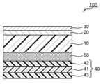
도 1 은, 본 발명의 하나의 실시형태에 의한 광학 적층체의 개략 단면도이다.1 is a schematic sectional view of an optical laminate according to one embodiment of the present invention.
이하, 본 발명의 대표적인 실시형태에 대해서 설명하는데, 본 발명은 이들 실시형태에는 한정되지 않는다.Hereinafter, exemplary embodiments of the present invention will be described, but the present invention is not limited to these embodiments.
A. 광학 적층체의 전체 구성A. Overall construction of optical laminate
도 1 은, 본 발명의 하나의 실시형태에 의한 광학 적층체의 개략 단면도이다. 본 실시형태의 광학 적층체 (100) 는, 편광자 (41) 와 응력 완화층 (50) 과 기재 (10) 와 제 1 산화물층 (20) 과 제 2 산화물층 (30) 을 이 순서로 갖는다. 이와 같은 구성을 가짐으로써, 본 발명의 실시형태에 의한 광학 적층체는, 화상 표시 장치의 배리어 필름 및 편광판의 양방으로서 기능할 수 있다. 실용적으로는, 편광자의 적어도 일방의 측에는 보호층 (42 및/또는 43) 이 형성된다 (도시 예에서는, 편광자 (41) 의 양측에 보호층 (42 및 43) 이 형성되어 있다). 이 경우, 대표적으로는, 편광자 (41) 는 편광판 (40) 으로서 광학 적층체에 도입될 수 있다. 제 1 산화물층 (20) 은, ZnO, Al 및 SiO2 를 포함한다. 제 2 산화물층 (30) 은, SiO2 로 구성되어 있다. 제 1 산화물층 (20) 의 두께는, 바람직하게는 10 ㎚ ∼ 100 ㎚ 이다. 제 2 산화물층 (30) 의 두께는, 바람직하게는 10 ㎚ ∼ 100 ㎚ 이다.1 is a schematic sectional view of an optical laminate according to one embodiment of the present invention. The
본 발명의 실시형태에 있어서는, 응력 완화층 (50) 의 탄성률은 0.01 ㎫ ∼ 70 ㎬ 이고, 또한, 두께는 13 ㎛ ∼ 200 ㎛ 이다. 응력 완화층은, 점착제로 구성되어도 되고, 점착제와 응력 완화체의 적층체로 구성되어도 된다. 편광자 (편광판) 와 기재 사이에 응력 완화층을 형성하고, 또한, 당해 응력 완화층의 탄성률 및 두께를 상기 소정의 범위로 설정함으로써, 이하의 효과가 얻어진다:광학 적층체에 있어서는 편광자의 치수 변화 (대표적으로는, 수축) 가 다른 구성 요소에 비해 현저하게 크다. 따라서, 편광자의 수축에 의한 응력이나 변형이 기재, 제 1 산화물층 및 제 2 산화물층에 전파하고, 결과적으로, 제 1 산화물층 및/또는 제 2 산화물층에 있어서 두께 방향으로 크랙이 발생하는 경우가 있다. 여기서, 상기한 바와 같이 편광자 (편광판) 와 기재 사이에 응력 완화층을 형성하고, 또한, 당해 응력 완화층의 탄성률 및 두께를 상기 소정의 범위로 설정함으로써, 상기 응력이나 변형의 전파가 완화된다. 그 결과, 편광자의 수축에서 주로 기인하는 크랙의 발생이 현저하게 억제되고, 제 1 산화물층과 제 2 산화물층의 적층 구조에 의한 우수한 배리어성이 유지될 수 있다. 따라서, 편광자와 배리어 필름 (기재와 제 1 산화물층과 제 2 산화물층의 적층체) 의 일체화가 가능해지고, 이것은, 화상 표시 장치의 박형화 및 제조 프로세스의 간략화에 현저하게 공헌할 수 있다. 이것은, 편광자와 배리어 필름을 일체화하여 비로소 인식된 과제를 해결하기 위해서 시행 착오함으로써 얻어진 지견이고, 예기치 못한 우수한 효과이다.In the embodiment of the present invention, the modulus of elasticity of the
광학 적층체는, 수분 및 가스 (예를 들어 산소) 에 대한 배리어성을 갖는다. 광학 적층체의 40 ℃, 90 %RH 조건 아래에서의 수증기 투과율 (투습도) 은, 바람직하게는 1.0 × 10⁻¹ g/㎡/24 hr 미만이다. 배리어성의 관점에서는, 투습도의 하한은 낮을수록 바람직하다. 투습도의 측정 한계는, 예를 들어 0.1 × 10⁻⁶ g/㎡/24 hr 정도이다. 하나의 실시형태에 있어서는, 디바이스 구성물로부터 시간 경과적으로 발생하는 아웃 가스를 방출한다는 관점에서, 투습도의 하한은, 예를 들어 0.1 × 10⁻⁴ g/㎡/24 hr 이다. 투습도의 바람직한 상한은, 용도에 따라 변동될 수 있다. 투습도의 상한은, 예를 들어 실내의 화상 표시 장치 (예를 들어, PC 디스플레이) 용도에서는 5.0 × 10⁻² g/㎡/24 hr 이고, 옥외의 화상 표시 장치 (디지털 사이니지) 용도에서는 3.0 × 10⁻² g/㎡/24 hr 이고, 차재 디스플레이 등의 실내 과혹 환경 용도에서는 1.0 × 10⁻² g/㎡/24 hr 이다. 광학 적층체의 60 ℃, 90 %RH 조건 아래에서의 가스 배리어성은, 바람직하게는 1.0 × 10⁻⁷ g/㎡/24 hr ∼ 0.5 g/㎡/24 hr 이고, 보다 바람직하게는 1.0 × 10⁻⁷ g/㎡/24 hr ∼ 0.1 g/㎡/24 hr 이다. 투습도 및 가스 배리어성이 이와 같은 범위이면, 광학 적층체를 화상 표시 장치에 첩합 (貼合) 한 경우에, 당해 화상 표시 장치를 공기 중의 수분 및 산소로부터 양호하게 보호할 수 있다. 또한, 투습도 및 가스 배리어성은 모두, JIS K7126-1 에 준하여 측정될 수 있다.The optical laminate has barrier properties to moisture and gas (for example, oxygen). The moisture vapor transmission rate (moisture permeability) of the optical laminate under the conditions of 40 캜 and 90% RH is preferably less than 1.0 10 -1 g / m 2/24 hr. From the viewpoint of barrier property, the lower the lower limit of the moisture permeability is, the better. The measurement limit of the moisture permeability is, for example, about 0.1 × 10 -6 g / m 2/24 hr. In one embodiment, the lower limit of the moisture permeability is, for example, 0.1 × 10 -4 g / m 2/24 hr from the viewpoint of releasing outgas generated over time from the device structure. The preferred upper limit of the moisture permeability may vary depending on the application. The upper limit of the moisture permeability is 5.0 × 10 -2 g / m 2/24 hr for an indoor image display device (for example, a PC display) and 3.0 × 10 -2 g / m 2/24 hr, and 1.0 × 10 -2 g / m 2/24 hr in the case of indoor aggressive environments such as on-vehicle displays. Castle gas barrier of below 60 ℃, 90% RH conditions for the optical multilayer body, preferably from 1.0 × 10 -7 g / ㎡ / 24 hr ~ 0.5 g / ㎡ / 24 hr , more preferably from 1.0 × 10 - 7 g / m 2/24 hr to 0.1 g / m 2/24 hr. When the optical laminate is bonded to an image display device, the image display device can be well protected from moisture and oxygen in the air if the moisture permeability and the gas barrier property are in such a range. In addition, both the moisture permeability and the gas barrier property can be measured in accordance with JIS K7126-1.
광학 적층체는, 바람직하게는 내약품성을 갖는다. 보다 상세하게는, 광학 적층체는, 바람직하게는 내산성 및 내알칼리성을 갖는다. 본 명세서에 있어서 「내산성」 이란, 2 % 의 염산 용액 (pH 0.3) 을 광학 적층체에 적하하고, 10 분 후에 염산 용액을 닦아낸 후의 투습도가 1.0 × 10⁻¹ g/㎡/24 hr 미만인 것을 말한다. 또, 「내알칼리성」 이란, 2 % 의 수산화나트륨 용액 (pH 13.7) 을 광학 적층체에 적하하고, 10 분 후에 수산화나트륨 용액을 닦아낸 후의 투습도가 1.0 × 10⁻¹ g/㎡/24 hr 미만인 것을 말한다. 상기와 같은 원하는 배리어성 및 투명성을 유지하면서, 이와 같은 우수한 내약품성을 실현한 것이, 본 발명의 성과의 하나이다.The optical laminate preferably has chemical resistance. More specifically, the optical laminate preferably has acid resistance and alkali resistance. In the present specification, the "acid resistance" means that the 2% hydrochloric acid solution (pH 0.3) is dropped onto the optical laminate and the water vapor permeability after wiping off the hydrochloric acid solution after 10 minutes is less than 1.0 × 10 -1 g / m 2/24 hr It says. "Alkali resistance" means that the water vapor permeability after dropping a 2% sodium hydroxide solution (pH 13.7) into the optical laminate and wiping off the sodium hydroxide solution after 10 minutes is less than 1.0 × 10 -1 g / m 2/24 hr It says. It is one of the achievements of the present invention that such excellent chemical resistance is realized while maintaining the desired barrier property and transparency as described above.
광학 적층체는, 바람직하게는 곡률 반경 7 ㎜, 보다 바람직하게는 곡률 반경 5 ㎜ 로 굴곡해도 균열 및 크랙이 발생하지 않는 굴곡성을 갖는다. 상기 소정의 제 1 산화물층과 제 2 산화물층의 적층 구조를 채용함으로써, 우수한 내약품성과 우수한 굴곡성 및 내열성 (후술) 을 양립할 수 있다.The optical laminate preferably has a bending property such that cracks and cracks do not occur even if the optical laminate is bent with a radius of curvature of 7 mm, more preferably a radius of curvature of 5 mm. By adopting the laminated structure of the predetermined first oxide layer and the second oxide layer, excellent chemical resistance, excellent bendability and heat resistance (described later) can be achieved.
광학 적층체는, 95 ℃ 에서 바람직하게는 500 시간, 보다 바람직하게는 600 시간, 더욱 바람직하게는 700 시간 가열해도 투습도가 1.0 × 10⁻¹ g/㎡/24 hr 미만인 내열성을 갖는다. 상기 소정의 제 1 산화물층과 제 2 산화물층의 적층 구조를 채용함으로써, 우수한 내약품성과 우수한 굴곡성 및 내열성을 양립할 수 있다.The optical laminate has a heat resistance of less than 1.0 x 10 < -1 > g / m < 2 > / 24 hr, even when heated at 95 deg. C, preferably 500 hours, more preferably 600 hours, more preferably 700 hours. By adopting the laminated structure of the predetermined first oxide layer and the second oxide layer, excellent chemical resistance, excellent bendability and heat resistance can be achieved.
하나의 실시형태에 있어서는, 본 발명의 광학 적층체는 장척상 (長尺狀) 이다. 장척상의 광학 적층체는, 예를 들어, 롤상으로 권회되어 보관 및/또는 운반될 수 있다. 광학 적층체는 굴곡성이 우수하므로, 롤상으로 권회되어도 문제는 발생하지 않는다. 이 경우, 편광자의 흡수축 방향은, 대표적으로는 장척 방향으로 실질적으로 평행이다. 이와 같은 구성이면, 광학 적층체를 이른바 롤투롤로 제조할 수 있다.In one embodiment, the optical laminate of the present invention is elongated. The elongated optical stack can be stored and / or transported, for example, in a rolled form. Since the optical laminate has excellent bendability, there is no problem even if the optical laminate is wound in a roll form. In this case, the absorption axis direction of the polarizer is typically substantially parallel to the longitudinal direction. With such a constitution, the optical laminate can be made of so-called Rollou roll.
필요에 따라, 편광판 (40) 과 응력 완화층 (50) 사이, 및/또는, 편광판 (40) 의 기재와 반대측에 위상차 층 (도시하지 않음) 이 형성되어도 된다. 위상차 층의 광학 특성 (예를 들어, 굴절률 타원체, 면내 위상차, 두께 방향 위상차, Nz 계수, 파장 분산 특성, 광 탄성 계수), 기계적 특성, 배치되는 수, 조합 등은, 목적에 따라 적절히 설정될 수 있다. 예를 들어, 편광판 (40) 의 기재와 반대측에, 역분산의 파장 의존성을 나타내고, 또한, 이른바 λ/4 판으로서 기능할 수 있는 위상차 층이 배치될 수 있다. 이 경우, 위상차 층의 지상축과 편광자의 흡수축이 이루는 각도는, 대표적으로는 약 45° 이다. 이와 같은 구성이면, 광학 적층체에 양호한 원 편광 기능이 부여되므로, 광학 적층체가 화상 표시 장치의 반사 방지 필름으로서도 양호하게 기능할 수 있다.A retardation layer (not shown) may be formed between the polarizing
이하, 광학 적층체의 구성 요소에 대해서 설명한다.Hereinafter, constituent elements of the optical laminate will be described.
B. 편광판B. Polarizer
상기한 바와 같이, 편광자 (41) 는, 대표적으로는, 편광판 (40) 으로서 광학 적층체에 도입될 수 있다. 편광판 (40) (실질적으로는 보호층 (42), 보호층 (42) 이 존재하지 않는 경우에는 편광자 (41)) 은, 대표적으로는 응력 완화층 (50) 을 개재하여 기재 (10) 에 첩합된다.As described above, the
B-1. 편광자 B-1. Polarizer
편광자 (41) 로는, 임의의 적절한 편광자가 채용될 수 있다. 예를 들어, 편광자를 형성하는 수지 필름은, 단층의 수지 필름이어도 되고, 2 층 이상의 적층체여도 된다.As the
단층의 수지 필름으로 구성되는 편광자의 구체예로는, 폴리비닐알코올 (PVA) 계 필름, 부분 포멀화 PVA 계 필름, 에틸렌·아세트산비닐 공중합체계 부분 비누화 필름 등의 친수성 고분자 필름에, 요오드나 이색성 염료 등의 이색성 물질에 의한 염색 처리 및 연신 처리가 실시된 것, PVA 의 탈수 처리물이나 폴리염화비닐의 탈염산 처리물 등 폴리엔계 배향 필름 등을 들 수 있다. 바람직하게는, 광학 특성이 우수하다는 점에서, PVA 계 필름을 요오드로 염색하고 1 축 연신하여 얻어진 편광자가 사용된다.Specific examples of the polarizer composed of the single-layer resin film include a hydrophilic polymer film such as a polyvinyl alcohol (PVA) film, a partially formalized PVA film, and an ethylene / vinyl acetate copolymerization system partially saponified film, Dyes such as dyestuffs, and polyene-based oriented films such as dehydrated PVA and dehydrochlorinated polyvinyl chloride films. Preferably, a polarizer obtained by dyeing a PVA-based film with iodine and uniaxially stretching is used from the viewpoint of excellent optical characteristics.
상기 요오드에 의한 염색은, 예를 들어, PVA 계 필름을 요오드 수용액에 침지함으로써 실시된다. 상기 1 축 연신의 연신 배율은, 바람직하게는 3 ∼ 7 배이다. 연신은, 염색 처리 후에 실시해도 되고, 염색하면서 실시해도 된다. 또, 연신하고 나서 염색해도 된다. 필요에 따라, PVA 계 필름에, 팽윤 처리, 가교 처리, 세정 처리, 건조 처리 등이 실시된다. 예를 들어, 염색 전에 PVA 계 필름을 물에 침지하여 물 세정함으로써, PVA 계 필름 표면의 오염이나 블로킹 방지제를 세정할 수 있을 뿐만 아니라, PVA 계 필름을 팽윤시켜 염색 불균일 등을 방지할 수 있다.The dyeing by iodine is carried out, for example, by immersing a PVA-based film in an iodine aqueous solution. The stretching ratio of the uniaxial stretching is preferably 3 to 7 times. The stretching may be performed after the dyeing treatment, or may be performed while dyeing. Further, it may be dyed after stretching. If necessary, swelling treatment, crosslinking treatment, washing treatment, drying treatment and the like are performed on the PVA film. For example, before the dyeing, the PVA film is immersed in water and washed with water to clean the contamination on the surface of the PVA film and the antiblocking agent, and the PVA film can be swollen to prevent uneven dyeing.
적층체를 사용하여 얻어지는 편광자의 구체예로는, 수지 기재와 당해 수지 기재에 적층된 PVA 계 수지층 (PVA 계 수지 필름) 의 적층체, 혹은, 수지 기재와 당해 수지 기재에 도포 형성된 PVA 계 수지층의 적층체를 사용하여 얻어지는 편광자를 들 수 있다. 수지 기재와 당해 수지 기재에 도포 형성된 PVA 계 수지층의 적층체를 사용하여 얻어지는 편광자는, 예를 들어, PVA 계 수지 용액을 수지 기재에 도포하고, 건조시켜 수지 기재 상에 PVA 계 수지층을 형성하여, 수지 기재와 PVA 계 수지층의 적층체를 얻는 것;당해 적층체를 연신 및 염색하여 PVA 계 수지층을 편광자로 하는 것;에 의해 제조될 수 있다. 본 실시형태에 있어서는, 연신은, 대표적으로는 적층체를 붕산 수용액 중에 침지시켜 연신하는 것을 포함한다. 또한, 연신은, 필요에 따라, 붕산 수용액 중에서의 연신 전에 적층체를 고온 (예를 들어, 95 ℃ 이상) 에서 공중 연신하는 것을 추가로 포함할 수 있다. 얻어진 수지 기재/편광자의 적층체는 그대로 사용해도 되고 (즉, 수지 기재를 편광자의 보호층으로 해도 되고), 수지 기재/편광자의 적층체로부터 수지 기재를 박리하고, 당해 박리면에 목적에 따른 임의의 적절한 보호층을 적층하여 사용해도 된다. 이와 같은 편광자의 제조 방법의 상세한 내용은, 예를 들어 일본 공개특허공보 2012-73580호에 기재되어 있다. 당해 공보는, 그 전체의 기재가 본 명세서에 참고로서 원용된다.Specific examples of the polarizer obtained by using the laminate include a laminate of a resin substrate and a PVA resin layer (PVA resin film) laminated on the resin substrate, or a laminate of a resin substrate and a PVA- And a polarizer obtained by using a laminate of a paper layer. A polarizer obtained by using a laminate of a resin substrate and a PVA resin layer formed on the resin substrate can be produced by, for example, applying a PVA resin solution to a resin substrate and drying to form a PVA resin layer on the resin substrate To obtain a laminate of a resin substrate and a PVA-based resin layer; stretching and staining the laminate to prepare a PVA-based resin layer as a polarizer; In the present embodiment, the stretching typically involves immersing the laminate in an aqueous solution of boric acid and stretching. In addition, the stretching may further include, if necessary, air-stretching the laminate at a high temperature (for example, 95 캜 or higher) before stretching in an aqueous solution of boric acid. The obtained laminate of the resin substrate / polarizer may be used as is (that is, the resin substrate may be the protective layer of the polarizer), the resin substrate is peeled from the laminate of the resin substrate / polarizer, May be laminated and used. The details of the method for producing such a polarizer are described, for example, in Japanese Laid-Open Patent Publication No. 2012-73580. This publication is incorporated herein by reference in its entirety.
편광자의 두께는, 바람직하게는 15 ㎛ 이하이고, 보다 바람직하게는 1 ㎛ ∼ 12 ㎛ 이고, 더욱 바람직하게는 3 ㎛ ∼ 10 ㎛ 이고, 특히 바람직하게는 3 ㎛ ∼ 8 ㎛ 이다. 편광자의 두께가 이와 같은 범위이면, 가열시의 컬을 양호하게 억제할 수 있고, 및, 양호한 가열시의 외관 내구성이 얻어진다. 또한, 편광자의 두께가 이와 같은 범위이면, 광학 적층체 (결과적으로, 유기 EL 표시 장치) 의 박형화에 공헌할 수 있다.The thickness of the polarizer is preferably 15 占 퐉 or less, more preferably 1 占 퐉 to 12 占 퐉, still more preferably 3 占 퐉 to 10 占 퐉, particularly preferably 3 占 퐉 to 8 占 퐉. When the thickness of the polarizer is in this range, curling at the time of heating can be suppressed well, and good durability in appearance at the time of heating can be obtained. Further, if the thickness of the polarizer is within this range, it can contribute to the thinness of the optical laminate (consequently, the organic EL display device).
편광자는, 바람직하게는, 파장 380 ㎚ ∼ 780 ㎚ 중 어느 것의 파장에서 흡수 이색성을 나타낸다. 편광자의 단체 투과율은, 바람직하게는 43.0 % ∼ 46.0 % 이고, 보다 바람직하게는 44.5 % ∼ 46.0 % 이다. 편광자의 편광도는, 바람직하게는 97.0 % 이상이고, 보다 바람직하게는 99.0 % 이상이고, 더욱 바람직하게는 99.9 % 이상이다.The polarizer preferably exhibits absorption dichroism at a wavelength of 380 nm to 780 nm. The light transmittance of the polarizer is preferably 43.0% to 46.0%, more preferably 44.5% to 46.0%. The degree of polarization of the polarizer is preferably 97.0% or more, more preferably 99.0% or more, and further preferably 99.9% or more.
B-2. 보호층 B-2. Protective layer
보호층 (42) 은, 편광자의 보호층으로서 사용할 수 있는 임의의 적절한 필름으로 형성된다. 당해 필름의 주성분이 되는 재료의 구체예로는, 트리아세틸셀룰로오스 (TAC) 등의 셀룰로오스계 수지나, 폴리에스테르계, 폴리비닐알코올계, 폴리카보네이트계, 폴리아미드계, 폴리이미드계, 폴리에테르술폰계, 폴리술폰계, 폴리스티렌계, 폴리노르보르넨계, 폴리올레핀계, (메트)아크릴계, 아세테이트계 등의 투명 수지 등을 들 수 있다. 또, (메트)아크릴계, 우레탄계, (메트)아크릴우레탄계, 에폭시계, 실리콘계 등의 열 경화형 수지 또는 자외선 경화형 수지 등도 들 수 있다. 이 밖에도, 예를 들어, 실록산계 폴리머 등의 유리질계 폴리머도 들 수 있다. 또, 일본 공개특허공보 2001-343529호 (WO01/37007) 에 기재된 폴리머 필름도 사용할 수 있다. 이 필름의 재료로는, 예를 들어, 측사슬에 치환 또는 비치환의 이미드기를 갖는 열가소성 수지와, 측사슬에 치환 또는 비치환의 페닐기 그리고 니트릴기를 갖는 열가소성 수지를 함유하는 수지 조성물을 사용할 수 있으며, 예를 들어, 이소부텐과 N-메틸말레이미드로 이루어지는 교호 공중합체와, 아크릴로니트릴·스티렌 공중합체를 갖는 수지 조성물을 들 수 있다. 당해 폴리머 필름은, 예를 들어, 상기 수지 조성물의 압출 성형물일 수 있다.The
본 발명의 광학 적층체는, 대표적으로는 화상 표시 장치의 시인측에 배치되며, 보호층 (42) 은, 대표적으로는 그 시인측에 배치된다. 따라서, 보호층 (42) 에는, 필요에 따라, 하드 코트 처리, 반사 방지 처리, 스티킹 방지 처리, 안티글레어 처리 등의 표면 처리가 실시되어 있어도 된다. 또한/혹은, 보호층 (42) 에는, 필요에 따라, 편광 선글라스를 통해서 시인하는 경우의 시인성을 개선하는 처리 (대표적으로는, (타)원 편광 기능을 부여하는 것, 초고위상차를 부여하는 것) 가 실시되어 있어도 된다. 이와 같은 처리를 실시함으로써, 편광 선글라스 등의 편광 렌즈를 통해서 표시 화면을 시인한 경우에도, 우수한 시인성을 실현할 수 있다. 따라서, 광학 적층체는, 옥외에서 사용될 수 있는 화상 표시 장치에도 적합하게 적용될 수 있다.The optical laminate of the present invention is typically disposed on the viewer side of the image display apparatus, and the
보호층 (42) 의 두께는, 바람직하게는 20 ㎛ ∼ 200 ㎛, 보다 바람직하게는 30 ㎛ ∼ 100 ㎛, 더욱 바람직하게는 35 ㎛ ∼ 95 ㎛ 이다.The thickness of the
보호층 (43) 은, 광학적으로 등방성인 것이 바람직하다. 본 명세서에 있어서 「광학적으로 등방성」 이란, 면내 위상차 Re(550) 이 0 ㎚ ∼ 10 ㎚ 이고, 두께 방향의 위상차 Rth(550) 이 ―10 ㎚ ∼ +10 ㎚ 인 것을 말한다. 기재의 면내 위상차 Re(550) 은 바람직하게는 0 ㎚ ∼ 5 ㎚ 이고, 두께 방향의 위상차 Rth(550) 은 바람직하게는 ―5 ㎚ ∼ +5 ㎚ 이다. 또한, 「Re(550)」 은, 23 ℃ 에 있어서의 파장 550 ㎚ 의 광으로 측정한 필름의 면내 위상차이고, 필름의 두께를 d (㎚) 로 했을 때, 식:Re = (nx ― ny) × d 에 의해 구해진다. 「Rth(550)」 은, 23 ℃ 에 있어서의 파장 550 ㎚ 의 광으로 측정한 필름의 두께 방향의 위상차이고, 필름의 두께를 d (㎚) 로 했을 때, 식:Rth = (nx ― nz) × d 에 의해 구해진다. 여기서, 「nx」 는 면내의 굴절률이 최대가 되는 방향 (즉, 지상축 방향) 의 굴절률이고, 「ny」 는 면내에서 지상축과 직교하는 방향 (즉, 진상축 방향) 의 굴절률이고, 「nz」 는 두께 방향의 굴절률이다.The
보호층 (43) 의 재료 및 두께 등은, 보호층 (42) 에 관해서 상기에서 설명한 바와 같다.The material, thickness, and the like of the
보호층 (42 및 43) 은, 대표적으로는, 임의의 적절한 접착제층 (예를 들어, PVA 계 수지 접착제층) 을 개재하여 편광자 (41) 에 첩합된다.The protective layers 42 and 43 are typically bonded to the
C. 응력 완화층C. Stress relieving layer
응력 완화층 (50) 은, 그 95 ℃ 에 있어서의 탄성률 (영률) 이 상기한 바와 같이 0.01 ㎫ ∼ 70 ㎬ 이고, 바람직하게는 0.03 ㎫ ∼ 5 ㎬ 이고, 보다 바람직하게는 0.05 ㎫ ∼ 0.3 ㎬ 이다. 응력 완화층의 탄성률이 이와 같은 범위이면, 편광자의 수축에서 기인하는 기재의 응력이 양호하게 완화될 수 있다. 그 결과, 제 1 산화물층 및/또는 제 2 산화물층에 있어서의 크랙의 발생이 현저하게 억제될 수 있다.As described above, the
응력 완화층의 95 ℃ 에 있어서의 전단 저장 탄성률 G' (95 ℃) 는, 바람직하게는 5.0 × 10⁴ ㎩ ∼ 1.0 × 10¹¹ ㎩ 이고, 보다 바람직하게는 1.5 × 10⁵ ㎩ ∼ 7.0 × 10⁹ ㎩ 이고, 더욱 바람직하게는 2.5 × 10⁵ ㎩ ∼ 4.0 × 10⁸ ㎩ 이다. 응력 완화층의 G' (95 ℃) 가 이와 같은 범위이면, 편광자의 수축에서 기인하는 응력 등의 전파가 양호하게 완화될 수 있다. 그 결과, 제 1 산화물층 및/또는 제 2 산화물층에 있어서의 크랙의 발생이 현저하게 억제될 수 있다. 또한, G' (95 ℃) 는, 동적 점탄성 측정에 의해 측정된다.The shear storage modulus G '(95 ° C) of the stress relieving layer at 95 ° C is preferably 5.0 × 10 4 Pa to 1.0 × 10 11 Pa, more preferably 1.5 × 10 5 Pa to 7.0 × 10 9 Pa, and more preferably 2.5 x 10 5 Pa to 4.0 x 10 8 Pa. When G '(95 캜) of the stress relaxation layer is in such a range, propagation such as stress caused by shrinkage of the polarizer can be satisfactorily mitigated. As a result, occurrence of cracks in the first oxide layer and / or the second oxide layer can be remarkably suppressed. Also, G '(95 캜) is measured by dynamic viscoelasticity measurement.
응력 완화층의 두께는, 상기한 바와 같이 13 ㎛ ∼ 200 ㎛ 이고, 바람직하게는 15 ㎛ ∼ 200 ㎛ 이고, 보다 바람직하게는 20 ㎛ ∼ 150 ㎛ 이다. 응력 완화층의 두께가 이와 같은 범위이면, 상기의 탄성률과의 상승적인 효과에 의해, 편광자의 수축에서 기인하는 기재의 응력이 양호하게 완화될 수 있다. 즉, 본 발명의 실시형태에 있어서는, 편광자와 기재 사이에 응력 완화층을 형성하고, 또한, 그 탄성률과 두께를 조합하여 최적화함으로써, 배리어 필름 및 편광판으로서 기능하는 광학 적층체에 있어서, 배리어 필름 및 편광판으로서의 우수한 특성을 유지하면서, 제 1 산화물층 및/또는 제 2 산화물층에 있어서의 크랙의 발생을 현저하게 억제할 수 있다.The thickness of the stress relieving layer is 13 탆 to 200 탆, preferably 15 탆 to 200 탆, and more preferably 20 탆 to 150 탆 as described above. When the thickness of the stress relieving layer is in this range, the stress of the base material due to the shrinkage of the polarizer can be satisfactorily mitigated by the synergistic effect with the above-mentioned elastic modulus. That is, in the embodiment of the present invention, in the optical laminate functioning as the barrier film and the polarizing plate by forming the stress relaxation layer between the polarizer and the substrate and optimizing the combination of the elastic modulus and the thickness, Generation of cracks in the first oxide layer and / or the second oxide layer can be remarkably suppressed while maintaining excellent characteristics as a polarizing plate.
응력 완화층은, 가시광 (예를 들어, 파장 550 ㎚ 의 광) 의 전광선 투과율이, 바람직하게는 85 % 이상이고, 보다 바람직하게는 90 % 이상이고, 더욱 바람직하게는 95 % 이상이다. 또, 응력 완화층은, 헤이즈가, 바람직하게는 1.5 % 이하이고, 보다 바람직하게는 1.0 % 이하이다.The stress relieving layer preferably has a total light transmittance of visible light (for example, light having a wavelength of 550 nm) of preferably 85% or more, more preferably 90% or more, still more preferably 95% or more. The stress relieving layer has a haze of preferably 1.5% or less, more preferably 1.0% or less.
응력 완화층으로는, 상기와 같은 특성을 갖는 임의의 적절한 구성이 채용될 수 있다. 구체적으로는 상기한 바와 같이, 응력 완화층은 점착제로 구성되어도 되고, 점착제와 응력 완화체의 적층체 (보다 상세하게는, 2 개의 점착제층과 당해 2 개의 점착제층의 사이에 배치된 응력 완화체를 갖는 적층체) 로 구성되어도 된다.As the stress relieving layer, any suitable configuration having the above-described characteristics can be employed. Specifically, as described above, the stress relieving layer may be composed of a pressure-sensitive adhesive, and may be a layered product of a pressure-sensitive adhesive and a stress relieving member (more specifically, two pressure-sensitive adhesive layers and a stress relieving member disposed between the two pressure- And the like).
응력 완화층에는, 상기와 같은 특성을 갖는 한 임의의 적절한 점착제 (점착제 조성물) 를 사용할 수 있다. 구체예로는, 아크릴계 점착제, 고무계 점착제, 비닐알킬에테르계 점착제, 실리콘계 점착제, 폴리에스테르계 점착제, 폴리아미드계 점착제, 우레탄계 점착제, 불소계 점착제, 에폭시계 점착제를 들 수 있다. 점착제는, 단독으로 사용해도 되고, 2 종 이상을 조합하여 사용해도 된다. 점착제의 형태 (점착 메커니즘) 도 또한, 임의의 적절한 형태가 채용될 수 있다. 구체예로는, 에멀션형 점착제, 용제형 (용액형) 점착제, 활성 에너지선 경화형 점착제, 열 용융형 점착제 (핫멜트형 점착제) 를 들 수 있다. 바람직하게는, 아크릴계 점착제이다. 모노머 성분의 선택의 폭이 넓고, 그로 인해 탄성률의 조정이 용이하기 때문이다. 또한, 아크릴계 점착제는, 우수한 투명성 및 내후성을 갖고, 저비용이라는 이점도 갖는다.Any appropriate pressure-sensitive adhesive (pressure-sensitive adhesive composition) may be used for the stress relieving layer as long as it has the above-described characteristics. Specific examples include acrylic pressure sensitive adhesives, rubber pressure sensitive adhesives, vinyl alkyl ether pressure sensitive adhesives, silicone pressure sensitive adhesives, polyester pressure sensitive adhesives, polyamide pressure sensitive adhesives, urethane pressure sensitive adhesives, fluorinated pressure sensitive adhesives and epoxy pressure sensitive adhesives. The pressure-sensitive adhesives may be used alone or in combination of two or more. The shape of the adhesive (adhesive mechanism) may also be any suitable shape. Specific examples thereof include an emulsion type adhesive, a solvent type (solution type) adhesive, an active energy ray curable adhesive, and a hot melt type adhesive (hot melt type adhesive). Preferably, it is an acrylic adhesive. This is because the range of selection of the monomer component is wide and therefore the adjustment of the modulus of elasticity is easy. Further, the acrylic pressure-sensitive adhesive has excellent transparency and weatherability and has an advantage of low cost.
아크릴계 점착제는, (메트)아크릴계 폴리머를 주성분으로서 포함한다. 점착제에 있어서의 아크릴계 폴리머의 함유량은, 점착제의 고형분 100 중량부에 대해서, 바람직하게는 65 중량부 이상 (예를 들어, 65 중량부 ∼ 100 중량부) 이며, 보다 바람직하게는 70 중량부 ∼ 99.999 중량부이다. 또한, 본 명세서에 있어서 「(메트)아크릴」 이란, 아크릴 및/또는 메타크릴을 의미한다.The acrylic pressure-sensitive adhesive contains (meth) acryl-based polymer as a main component. The content of the acrylic polymer in the pressure-sensitive adhesive is preferably 65 parts by weight or more (for example, 65 parts by weight to 100 parts by weight), more preferably 70 parts by weight to 99.999 parts by weight, per 100 parts by weight of the solid content of the pressure- Parts by weight. In the present specification, "(meth) acryl" means acryl and / or methacryl.
(메트)아크릴계 폴리머를 구성하는 모노머 성분으로는, 대표적으로는, 알킬(메트)아크릴레이트, 하이드록시알킬(메트)아크릴레이트, (메트)아크릴산, 복소 고리 함유 아크릴 모노머, 아크릴아미드, 글리시딜아크릴레이트를 들 수 있다. 모노머 성분의 종류, 조합 및 공중합비 등을 조정함으로써, 원하는 탄성률을 갖는 점착제를 얻을 수 있다.Examples of the monomer component constituting the (meth) acrylic polymer include alkyl (meth) acrylate, hydroxyalkyl (meth) acrylate, (meth) acrylic acid, heterocyclic-containing acrylic monomer, acrylamide, glycidyl Acrylate. By adjusting the kind, combination and copolymerization ratio of the monomer components, a pressure-sensitive adhesive having a desired elastic modulus can be obtained.
점착제 (점착제 조성물) 는, 가교제를 함유해도 된다. 또한, 점착제 (점착제 조성물) 는, 임의의 적절한 첨가제를 함유해도 된다. 첨가제의 구체예로는, 점착 부여제, 가소제, 유리 섬유, 충전제, 안료, 착색제, 산화 방지제, 자외선 흡수제, 실란 커플링제, 광 확산성 미립자를 들 수 있다. 첨가제의 함유량, 종류, 수, 조합 등은 목적에 따라 적절히 설정될 수 있다.The pressure-sensitive adhesive (pressure-sensitive adhesive composition) may contain a crosslinking agent. The pressure-sensitive adhesive (pressure-sensitive adhesive composition) may contain any suitable additives. Specific examples of the additive include a tackifier, a plasticizer, a glass fiber, a filler, a pigment, a colorant, an antioxidant, an ultraviolet absorber, a silane coupling agent, and a light diffusing fine particle. The content, type, number, combination, and the like of the additive can be appropriately set according to the purpose.
본 발명의 실시형태에 있어서는, 점착제 (점착제 조성물) 는, 탄성률을 제어할 목적으로, 충전제 (필러) 를 함유할 수 있다. 필러의 구체예로는, 폴리스티렌, 폴리카보네이트 등의 유기물로 이루어지는 유기물 필러;티타니아 (TiO2), 실리카 (SiO2), 알루미나 (Al2O3), 지르코니아 (ZrO2), 칼시아 (CaO), 마그네시아 (MgO) 등의 금속 산화물 또는 비금속 산화물, 혹은, 동 (Cu), 은 (Ag), 금 (Au), 알루미늄 (Al), 팔라듐 (Pd), 티탄 (Ti), 니켈 (Ni) 등의 금속으로 이루어지는 무기물 필러를 들 수 있다. 필러의 배합비는, 필러의 종류나 목적으로 하는 탄성률에 따라 적절히 선택될 수 있다. 필러는, 예를 들어, 점착제 (점착제 조성물) 의 총중량에 대해서 10 중량% ∼ 70 중량% 의 비율로 함유될 수 있다. 필러의 형상으로는, 목적에 따라 임의의 적절한 형상이 채용될 수 있다. 구체예로는, 진구상 (眞球狀), 타원 구상, 침상 (針狀), 원반상, 별형, 인편상 (鱗片狀) 을 들 수 있다. 필러의 사이즈도 또한, 목적에 따라 임의의 적절한 사이즈가 채용될 수 있다. 필러의 사이즈는, 예를 들어 10 ㎚ 정도의 나노 오더로부터 10 ㎛ 정도의 마이크로 오더까지 변동될 수 있다. 필러의 상세한 내용은, 예를 들어 WO2009/145005 에 기재되어 있다. 이 공보의 기재는, 본 명세서에 참고로서 원용된다.In the embodiment of the present invention, the pressure-sensitive adhesive (pressure-sensitive adhesive composition) may contain a filler (filler) for the purpose of controlling the modulus of elasticity. Specific examples of the filler include organic fillers made of organic materials such as polystyrene and polycarbonate; inorganic fillers such as titania (TiO 2 ), silica (SiO 2 ), alumina (Al 2 O 3 ), zirconia (ZrO 2 ) (Ag), gold (Au), aluminum (Al), palladium (Pd), titanium (Ti), nickel (Ni) or the like, or a metal oxide or nonmetal oxide such as magnesium oxide Of an inorganic filler composed of a metal. The compounding ratio of the filler can be appropriately selected according to the type of filler and the intended modulus of elasticity. The filler may be contained in a proportion of, for example, 10% by weight to 70% by weight based on the total weight of the pressure-sensitive adhesive (pressure-sensitive adhesive composition). As the shape of the filler, any appropriate shape may be employed depending on the purpose. Specific examples include spheroid, ellipsoidal, acicular, circular, star-shaped, and scaly-shaped. The size of the filler may also be any suitable size depending on the purpose. The size of the filler can be varied, for example, from a nano order of about 10 nm to a micro order of about 10 m. The details of the filler are described, for example, in WO2009 / 145005. The description of this publication is incorporated herein by reference.
점착제의 상세한 구성은, 예를 들어, 일본 공개특허공보 2005-307034호, 일본 공개특허공보 2007-277510호, 일본 공개특허공보 2012-87240호에 기재되어 있다. 이들 공보의 기재는, 본 명세서에 참고로서 원용된다.The detailed structure of the pressure-sensitive adhesive is described, for example, in Japanese Patent Application Laid-Open No. 2005-307034, Japanese Patent Application Laid-Open No. 2007-277510, and Japanese Laid-Open Patent Publication No. 2012-87240. The descriptions of these publications are incorporated herein by reference.
응력 완화층이 점착제와 응력 완화체의 적층체 (보다 상세하게는, 2 개의 점착제층과 당해 2 개의 점착제층의 사이에 배치된 응력 완화체를 갖는 적층체) 로 구성되어 있는 경우, 응력 완화체는, 95 ℃ 에 있어서의 열수축률이, 바람직하게는 0.5 % 이하이고, 보다 바람직하게는 0.3 % 이하이고, 더욱 바람직하게는 0.1 % 이하이다. 또한, 열수축률은, JIS K 7133 에 준하여 측정될 수 있다. 또한, 점착제는, 상기의 점착제가 사용될 수 있다.When the stress relieving layer is composed of a laminate of the pressure-sensitive adhesive and the stress relieving member (more specifically, a laminate having two pressure-sensitive adhesive layers and a stress relieving member disposed between the two pressure-sensitive adhesive layers) Is preferably 0.5% or less, more preferably 0.3% or less, and further preferably 0.1% or less, at 95 캜. The heat shrinkage ratio can be measured in accordance with JIS K7133. As the pressure-sensitive adhesive, the above-mentioned pressure-sensitive adhesive may be used.
응력 완화체를 형성하는 재료로는, 상기와 같은 특성을 갖는 한 임의의 적절한 재료를 사용할 수 있다. 재료로는, 유기 재료와 무기 재료로 대별된다.As the material for forming the stress relieving member, any appropriate material can be used as long as it has the above-mentioned characteristics. The material is roughly classified into an organic material and an inorganic material.
유기 재료의 구체예로는, 폴리에틸렌테레프탈레이트나 폴리에틸렌나프탈레이트 등의 폴리에스테르계 폴리머, 디아세틸셀룰로오스나 트리아세틸셀룰로오스 등의 셀룰로오스계 폴리머, 폴리메틸메타크릴레이트 등의 아크릴계 폴리머, 폴리스티렌이나 아크릴로니트릴·스티렌 공중합체 (AS 수지) 등의 스티렌계 폴리머, 폴리카보네이트계 폴리머, 폴리에틸렌, 폴리프로필렌, 시클로계 또는 노르보르넨 구조를 갖는 폴리올레핀, 에틸렌·프로필렌 공중합체 등의 폴리올레핀계 폴리머, 염화비닐계 폴리머, 나일론이나 방향족 폴리아미드 등의 아미드계 폴리머, 이미드계 폴리머, 술폰계 폴리머, 폴리에테르술폰계 폴리머, 폴리에테르에테르케톤계 폴리머, 폴리페닐렌술파이드계 폴리머, 비닐알코올계 폴리머, 염화비닐리덴계 폴리머, 비닐부티랄계 폴리머, 아릴레이트계 폴리머, 폴리옥시메틸렌계 폴리머, 에폭시계 폴리머를 들 수 있다. 이들 폴리머는, 단독으로 사용해도 되고 2 종 이상을 병용 (예를 들어, 블렌드, 공중합) 해도 된다.Specific examples of the organic material include polyester-based polymers such as polyethylene terephthalate and polyethylene naphthalate, cellulose-based polymers such as diacetylcellulose and triacetylcellulose, acrylic polymers such as polymethylmethacrylate, polystyrene and acrylonitrile A styrene copolymer such as styrene copolymer (AS resin), a polyolefin-based polymer such as a polycarbonate-based polymer, a polyethylene, a polypropylene, a cycloolefin-based or norbornene-structured polyolefin, or an ethylene-propylene copolymer, , Amide polymers such as nylon and aromatic polyamides, imide polymers, sulfone polymers, polyether sulfone polymers, polyether ether ketone polymers, polyphenylene sulfide polymers, vinyl alcohol polymers, vinylidene chloride polymers , Vinyl butyral based polymer, An acrylate-based polymer, a polyoxymethylene-based polymer, and an epoxy-based polymer. These polymers may be used alone or in combination of two or more (for example, blended or copolymerized).
무기 재료의 구체예로는, 소다라임 유리, 무알칼리 유리 등의 실리카 유리, 붕규산 유리, 석영 유리, 지르코니아 (ZrO2), 알루미나 (Al2O3), 반디석 (CaF2) 등의 투광성 결정체를 들 수 있다.Specific examples of the inorganic material include transparent glass such as silica glass such as soda lime glass and alkali-free glass, borosilicate glass, quartz glass, zirconia (ZrO 2 ), alumina (Al 2 O 3 ), and hemidite (CaF 2 ) .
응력 완화체에는, 목적에 따라 임의의 적절한 첨가제가 포함되어 있어도 된다. 첨가제로는, 예를 들어, 충전제, 자외선 흡수제, 산화 방지제, 활제 (滑劑), 가소제, 이형제, 착색 방지제, 난연제, 핵제, 대전 방지제, 안료, 착색제를 들 수 있다. 첨가제의 함유량, 종류, 수, 조합 등은 목적에 따라 적절히 설정될 수 있다. 첨가제의 상세한 내용은, 점착제에 관해서 설명한 바와 같다. 또, 탄성률의 제어에 대해서도 점착제에 관해서 설명한 바와 같다.The stress relieving material may contain any suitable additive depending on the purpose. Examples of the additive include fillers, ultraviolet absorbers, antioxidants, lubricants, plasticizers, mold release agents, coloring inhibitors, flame retardants, nucleating agents, antistatic agents, pigments and colorants. The content, type, number, combination, and the like of the additive can be appropriately set according to the purpose. The details of the additive are as described for the pressure-sensitive adhesive. The control of the modulus of elasticity is also described for the pressure-sensitive adhesive.
D. 기재D. Substrate
기재 (10) 는, 바람직하게는 투명하다. 기재는, 가시광 (예를 들어, 파장 550 ㎚ 의 광) 의 전광선 투과율이, 바람직하게는 85 % 이상이고, 보다 바람직하게는 90 % 이상이고, 더욱 바람직하게는 95 % 이상이다.The
기재 (10) 는, 하나의 실시형태에 있어서는, 광학적으로 등방성이다. 이와 같은 구성이면, 광학 적층체를 화상 표시 장치에 적용한 경우에 당해 화상 표시 장치의 표시 특성에 대한 악영향을 방지할 수 있다.The
기재의 평균 굴절률은, 바람직하게는 1.7 미만이고, 보다 바람직하게는 1.59 이하이고, 더욱 바람직하게는 1.4 ∼ 1.55 이다. 평균 굴절률이 이와 같은 범위이면, 이면 반사를 억제할 수 있고, 높은 광 투과율을 달성할 수 있다는 이점을 갖는다.The average refractive index of the substrate is preferably less than 1.7, more preferably not more than 1.59, and further preferably 1.4 to 1.55. When the average refractive index is in this range, the back reflection can be suppressed and an advantage of being able to achieve a high light transmittance can be obtained.
기재의 제 1 산화물층측의 표면의 표면 조도 Ra 는, 바람직하게는 0.30 ㎚ 이상이고, 보다 바람직하게는 0.40 ㎚ 이상이고, 더욱 바람직하게는 0.50 ㎚ 이상이고, 특히 바람직하게는 0.60 ㎚ 이상이다. 당해 표면의 표면 조도 Ra 의 상한은, 예를 들어 50 ㎚ 이다. 당해 표면의 표면 조도가 이와 같은 범위이면, 상기한 바와 같이, 기재와 제 1 산화물층의 우수한 밀착성이 실현되고, 결과적으로, 편광자의 수축에서 기인하는 제 1 산화물층 및/또는 제 2 산화물층의 크랙 (대표적으로는, 두께 방향의 크랙) 이 더욱 현저하게 억제될 수 있다. 이와 같은 표면 조도는, 임의의 적절한 조면화 처리에 의해 실현될 수 있다. 조면화 처리로는, 예를 들어, 엠보스 가공, 샌드 블라스트, 연신 절곡, 미립자의 도입을 들 수 있다. 표면 조도 Ra 는, JIS B 0601 에 준하여 측정될 수 있다.The surface roughness Ra of the surface of the substrate on the side of the first oxide layer is preferably 0.30 nm or more, more preferably 0.40 nm or more, still more preferably 0.50 nm or more, and particularly preferably 0.60 nm or more. The upper limit of the surface roughness Ra of the surface is, for example, 50 nm. When the surface roughness of the surface is in this range, as described above, excellent adhesion between the substrate and the first oxide layer is realized, and consequently, the first oxide layer and / or the second oxide layer The crack (typically, the crack in the thickness direction) can be suppressed more remarkably. Such surface roughness can be realized by any appropriate roughing process. Examples of the roughening treatment include embossing, sand blasting, stretching bending, and introduction of fine particles. The surface roughness Ra can be measured in accordance with JIS B 0601.
기재를 구성하는 재료로는, 상기 특성을 만족할 수 있는 임의의 적절한 재료를 사용할 수 있다. 기재를 구성하는 재료로는, 예를 들어, 노르보르넨계 수지나 올레핀계 수지 등의 공액계를 갖지 않는 수지, 락톤 고리나 글루타르이미드 고리 등의 고리형 구조를 아크릴계 주사슬 중에 갖는 수지, 폴리에스테르계 수지, 폴리카보네이트계 수지를 들 수 있다. 이와 같은 재료이면, 기재를 형성했을 때에, 분자 사슬의 배향에 수반하는 위상차의 발현을 작게 억제할 수 있다.As the material constituting the base material, any suitable material that can satisfy the above characteristics can be used. Examples of the material constituting the substrate include a resin having no conjugated system such as a norbornene resin or an olefin resin, a resin having a cyclic structure such as a lactone ring or a glutarimide ring in an acrylic main chain, An ester-based resin, and a polycarbonate-based resin. With such a material, it is possible to suppress the occurrence of the phase difference due to the orientation of the molecular chains to be small when the substrate is formed.
기재는, 다른 실시형태에 있어서는, 소정의 위상차를 가지고 있어도 된다. 예를 들어, 기재가 이른바 λ/4 판으로서 기능할 수 있는 면내 위상차를 가지고 있어도 된다. 이와 같은 구성이면, 위상차 층을 별도 배치하는 일 없이, 광학 적층체에 양호한 원 편광 기능이 부여되므로, 광학 적층체가 화상 표시 장치의 배리어 필름으로서 뿐만 아니라 반사 방지 필름으로서도 양호하게 기능할 수 있다. 이 경우, 기재의 지상축과 편광자 (41) 의 흡수축이 이루는 각도는, 대표적으로는 약 45° 이다. 이와 같은 기재는, 예를 들어, 노르보르넨계 수지나 폴리카보네이트계 수지의 필름을 적절한 조건으로 연신함으로써 형성될 수 있다.In another embodiment, the substrate may have a predetermined retardation. For example, the substrate may have an in-plane retardation capable of functioning as a so-called? / 4 plate. With this configuration, since the optical laminate is provided with a good circular polarization function without separately arranging the retardation layer, the optical laminate can function well as an anti-reflection film as well as a barrier film of an image display apparatus. In this case, the angle formed by the slow axis of the substrate and the absorption axis of the
기재의 두께는, 바람직하게는 10 ㎛ ∼ 50 ㎛ 이하이고, 보다 바람직하게는 20 ㎛ ∼ 35 ㎛ 이하이다.The thickness of the substrate is preferably 10 to 50 mu m, more preferably 20 to 35 mu m.
E. 제 1 산화물층E. First oxide layer
제 1 산화물층 (20) 은, 상기한 바와 같이, ZnO, Al 및 SiO2 를 포함한다. 제 1 산화물층은, 전체 중량에 대해서, Al 을 바람직하게는 2.5 중량% ∼ 3.5 중량%, SiO2 를 바람직하게는 20.0 중량% ∼ 62.4 중량% 의 비율로 포함한다. ZnO 는, 바람직하게는 잔량이다. ZnO 를 이와 같은 범위로 함유함으로써, 비정성 (非晶性), 배리어성, 굴곡성 및 내열성이 우수한 층을 형성할 수 있다. Al 을 이와 같은 범위로 함유함으로써, 제 1 산화물층은 대표적으로는 스퍼터링으로 형성되는 바, 타겟의 도전율을 증대시킬 수 있다. SiO2 를 이와 같은 범위로 함유함으로써, 이상 방전을 발생시키는 일 없이, 또한, 배리어성을 저해하는 일 없이, 제 1 산화물층의 굴절률을 작게 할 수 있다.A
제 1 산화물층의 두께는, 상기한 바와 같이 바람직하게는 10 ㎚ ∼ 100 ㎚ 이고, 보다 바람직하게는 10 ㎚ ∼ 60 ㎚ 이고, 더욱 바람직하게는 20 ㎚ ∼ 40 ㎚ 이다. 두께가 이와 같은 범위이면, 높은 광 투과성과 우수한 배리어성을 양립할 수 있다는 이점을 갖는다.The thickness of the first oxide layer is preferably 10 nm to 100 nm, more preferably 10 nm to 60 nm, and still more preferably 20 nm to 40 nm, as described above. When the thickness is in this range, it has an advantage that both high light transmittance and excellent barrier property can be achieved.
제 1 산화물층의 평균 굴절률은, 바람직하게는 1.59 ∼ 1.80 이다. 평균 굴절률이 이와 같은 범위이면, 높은 광 투과성을 달성할 수 있다는 이점을 갖는다.The average refractive index of the first oxide layer is preferably 1.59 to 1.80. If the average refractive index is in this range, it has an advantage that high light transmittance can be achieved.
제 1 산화물층은, 바람직하게는 투명하다. 제 1 산화물층은, 가시광 (예를 들어, 파장 550 ㎚ 의 광) 의 전광선 투과율이, 바람직하게는 85 % 이상이고, 보다 바람직하게는 90 % 이상이고, 더욱 바람직하게는 95 % 이상이다.The first oxide layer is preferably transparent. The first oxide layer preferably has a total light transmittance of visible light (for example, light having a wavelength of 550 nm) of preferably 85% or more, more preferably 90% or more, and still more preferably 95% or more.
제 1 산화물층은, 대표적으로는 스퍼터링에 의해 기재 상에 형성될 수 있다. 제 1 산화물층은, 예를 들어, Al, SiO2 및 ZnO 를 포함하는 스퍼터링 타겟을 사용하고, 산소를 함유시킨 불활성 가스 분위기하에 있어서, 스퍼터링법에 의해 형성될 수 있다. 스퍼터링 방법으로는, 마그네트론 스퍼터링법, RF 스퍼터링법, RF 중첩 DC 스퍼터링법, 펄스 스퍼터법, 듀얼 마그네트론 스퍼터링법 등을 채용할 수 있다. 기판의 가열 온도는 예를 들어 ―8 ℃ ∼ 200 ℃ 이다. 산소와 불활성 가스의 분위기 가스 전체에 대한 산소의 가스 분압은, 예를 들어 0.05 이상이다.The first oxide layer may be typically formed on the substrate by sputtering. The first oxide layer can be formed by a sputtering method under an inert gas atmosphere containing oxygen using, for example, a sputtering target containing Al, SiO 2 and ZnO. As the sputtering method, a magnetron sputtering method, an RF sputtering method, an RF superposition DC sputtering method, a pulse sputtering method, a dual magnetron sputtering method, or the like can be adopted. The heating temperature of the substrate is, for example, -8 캜 to 200 캜. The gas partial pressure of oxygen with respect to the entire atmospheric gas of oxygen and inert gas is, for example, 0.05 or more.
제 1 산화물층을 구성하는 AZO 막 및 그 제조 방법의 상세한 내용에 대해서는, 예를 들어 일본 공개특허공보 2013-189657호에 기재되어 있다. 당해 공보의 기재는, 본 명세서에 참고로서 원용된다.Details of the AZO film constituting the first oxide layer and the manufacturing method thereof are described in, for example, Japanese Laid-Open Patent Publication No. 2013-189657. The description of such a publication is incorporated herein by reference.
F. 제 2 산화물층F. Second oxide layer
제 2 산화물층 (30) 은, 상기한 바와 같이, SiO2 로 구성된다 (불가피 불순물도 포함될 수 있다). 이와 같은 제 2 산화물층을 제 1 산화물층의 표면에 형성함으로써, 제 1 산화물층에 의한 양호한 특성을 유지하면서, 광학 적층체의 내약품성 및 투명성을 현격히 향상시킬 수 있다. 또한, 제 2 산화물층은 저굴절률층으로서 기능할 수 있으므로, 광학 적층체에 양호한 반사 방지 특성을 부여할 수 있다.The
제 2 산화물층의 두께는, 상기한 바와 같이 바람직하게는 10 ㎚ ∼ 100 ㎚ 이고, 보다 바람직하게는 50 ㎚ ∼ 100 ㎚ 이고, 더욱 바람직하게는 60 ㎚ ∼ 100 ㎚ 이다. 두께가 이와 같은 범위이면, 높은 광 투과성과 우수한 배리어성과 우수한 내약품성을 양립할 수 있다는 이점을 갖는다.The thickness of the second oxide layer is preferably 10 nm to 100 nm, more preferably 50 nm to 100 nm, and still more preferably 60 nm to 100 nm, as described above. When the thickness is in this range, it has an advantage that high light transmittance, excellent barrier property and excellent chemical resistance can be compatible.
제 2 산화물층의 평균 굴절률은, 바람직하게는 1.44 ∼ 1.50 이다. 그 결과, 제 2 산화물층은, 저굴절률층 (반사 방지층) 으로서 양호하게 기능할 수 있다.The average refractive index of the second oxide layer is preferably 1.44 to 1.50. As a result, the second oxide layer can function well as a low refractive index layer (antireflection layer).
제 2 산화물층은, 바람직하게는 투명하다. 제 2 산화물층은, 가시광 (예를 들어, 파장 550 ㎚ 의 광) 의 전광선 투과율이, 바람직하게는 85 % 이상이고, 보다 바람직하게는 90 % 이상이고, 더욱 바람직하게는 95 % 이상이다.The second oxide layer is preferably transparent. The second oxide layer preferably has a total light transmittance of visible light (for example, light having a wavelength of 550 nm) of preferably 85% or more, more preferably 90% or more, and still more preferably 95% or more.
제 2 산화물층은, 대표적으로는 스퍼터링에 의해 제 1 산화물층 상에 형성될 수 있다. 제 2 산화물층은, 예를 들어, Si, SiC, SiN 또는 SiO 를 타겟으로 하고, 산소를 함유한 불활성 가스 (예를 들어, 아르곤, 질소, CO, CO2, 및 이들의 혼합 가스) 를 사용하여 스퍼터를 실시함으로써 형성될 수 있다. 제 1 산화물층 및 제 2 산화물층은 모두 SiO2 를 포함하므로, 제 1 산화물층과 제 2 산화물층의 밀착성은 매우 우수한 것이 된다. 이로부터, 제 1 산화물층과 제 2 산화물층의 계면에서 충분한 배리어 기능을 발현시키기 위해서는, 제 1 산화물층의 두께는, 상기한 바와 같이 10 ㎚ 이상인 것이 바람직하다. 그 이유로는, 성장 초기막인, 이른바 인큐베이션 레이어의 비율을 충분히 작게 할 수 있어, 목적으로 하는 물성을 갖는 산화물층을 형성할 수 있기 때문이다. 또, 제 1 산화물층과 제 2 산화물층의 토탈 두께는, 바람직하게는 200 ㎚ 이하이고, 보다 바람직하게는 140 ㎚ 이하이다.The second oxide layer may be typically formed on the first oxide layer by sputtering. The second oxide layer is formed by using an inert gas containing oxygen (for example, argon, nitrogen, CO, CO 2 , and a mixed gas thereof) with Si, SiC, And then performing sputtering. Since both the first oxide layer and the second oxide layer include SiO 2 , the adhesion between the first oxide layer and the second oxide layer is extremely excellent. Thus, in order to exhibit a sufficient barrier function at the interface between the first oxide layer and the second oxide layer, the thickness of the first oxide layer is preferably 10 nm or more as described above. The reason for this is that the ratio of the so-called incubation layer, which is the initial growth film, can be made sufficiently small, and an oxide layer having desired physical properties can be formed. The total thickness of the first oxide layer and the second oxide layer is preferably 200 nm or less, and more preferably 140 nm or less.
G. 광학 적층체의 용도G. Use of optical laminate
본 발명의 광학 적층체는, 화상 표시 장치의 배리어층 (배리어 필름) 및 편광판의 양방의 기능을 갖는 광학 부재로서 적합하게 사용될 수 있다. 보다 상세하게는, 본 발명의 광학 적층체는, 액정 표시 장치 및 유기 EL 표시 장치, 바람직하게는 유기 EL 표시 장치, 보다 바람직하게는 굴곡 가능한 유기 EL 표시 장치의 광학 부재로서 사용될 수 있다.The optical laminate of the present invention can be suitably used as an optical member having both functions of a barrier layer (barrier film) and a polarizing plate of an image display apparatus. More specifically, the optical laminate of the present invention can be used as a liquid crystal display device and an organic EL display device, preferably an organic EL display device, more preferably an optical member of a bendable organic EL display device.
실시예Example
이하, 실시예에 의해 본 발명을 구체적으로 설명하는데, 본 발명은 이들 실시예에 의해 한정되는 것은 아니다. 또한, 각 특성의 측정 방법은 이하와 같다.Hereinafter, the present invention will be described concretely with reference to examples, but the present invention is not limited to these examples. The measurement method of each characteristic is as follows.
(1) 두께(1) Thickness
제 1 산화물층 및 제 2 산화물층의 두께는, 투과형 전자 현미경 (히타치 제작소 제조 H-7650) 을 사용하여 단면 (斷面) 을 관찰하고, 측정을 실시하였다. 광학 적층체의 그 밖의 구성 요소의 두께는 막두께계 (Peacock 사 제조 디지털 다이얼 게이지 DG-205) 를 사용하여 측정하였다.The thicknesses of the first oxide layer and the second oxide layer were measured by observing a cross section using a transmission electron microscope (H-7650 manufactured by Hitachi, Ltd.). The thickness of the other components of the optical laminate was measured using a film thickness meter (digital dial gauge DG-205 manufactured by Peacock).
(2) 탄성률(2) Elastic modulus
실시예 및 비교예에서 사용한 응력 완화층에 대해서, 동적 점탄성 측정 장치 (상품명:ARES, 레오메트릭스사 제조) 에 의해, 저장 탄성률 G' 의 온도 의존성을 측정하고, 95 ℃ 에 있어서의 측정값 G' (95 ℃) 를 탄성률로 하였다.The temperature dependence of the storage elastic modulus G 'was measured by a dynamic viscoelasticity measuring apparatus (trade name: ARES, manufactured by Rheometrics Co.) for the stress relieving layers used in the examples and the comparative examples, and the measured value G' (95 deg. C) as the elastic modulus.
(3) 신뢰성(3) Reliability
실시예 및 비교예에서 얻어진 광학 적층체를 50 ㎜ × 50 ㎜ 사이즈로 잘라내고, 측정 시료로 하였다. 이 측정 시료를 석영 유리에 첩합하고, 95 ℃ 의 오븐에 1000 시간 보관하고, 보관 후의 투습도를 측정하고, 이하의 기준으로 평가하였다.The optical laminate obtained in Examples and Comparative Examples was cut into a size of 50 mm x 50 mm and used as a measurement sample. This measurement sample was bonded to quartz glass, stored in an oven at 95 ° C for 1000 hours, and the moisture permeability after storage was measured and evaluated according to the following criteria.
○:1.0 × 10⁻¹ g/㎡/24 hr 미만?: Less than 1.0 × 10 -1 g / m 2/24 hr
×:1.0 × 10⁻¹ g/㎡/24 hr 이상×: 1.0 × 10 -1 g / m 2/24 hr or more
(4) 투습도(4) Water vapor permeability
실시예 및 비교예에서 얻어진 광학 적층체를 10 ㎝Φ 의 원 형상으로 잘라내고, 측정 시료로 하였다. 이 측정 시료에 대해서, 테크노록스사 제조 「DELTAPERM」 을 사용하여, 40 ℃, 90 %RH 의 시험 조건으로 투습도를 측정하였다.The optical laminate obtained in Examples and Comparative Examples was cut into a circular shape of 10 cm? To obtain a measurement sample. For this measurement sample, the moisture permeability was measured under the test conditions of 40 DEG C and 90% RH by using "DELTAPERM" manufactured by Technorox.
(5) 내약품성(5) Chemical resistance
실시예 및 비교예에서 얻어진 광학 적층체를 100 ㎜ × 100 ㎜ 사이즈로 잘라내고, 측정 시료로 하였다. 2 % 의 수산화나트륨 용액 (pH 13.7) 을 측정 시료에 적하하고, 10 분 후에 수산화나트륨 용액을 닦아내어, 투습도를 측정하고, 이하의 기준으로 평가하였다.The optical laminate obtained in Examples and Comparative Examples was cut into a size of 100 mm x 100 mm and used as a measurement sample. 2% sodium hydroxide solution (pH 13.7) was dropped on the measurement sample, and 10 minutes later, the sodium hydroxide solution was wiped off and the moisture permeability was measured and evaluated according to the following criteria.
○:1.0 × 10⁻¹ g/㎡/24 hr 미만 ?: Less than 1.0 × 10 -1 g / m 2/24 hr
×:1.0 × 10⁻¹ g/㎡/24 hr 이상×: 1.0 × 10 -1 g / m 2/24 hr or more
<실시예 1> ≪ Example 1 >
(적층 배리어 필름의 제조) (Preparation of laminated barrier film)
시판되는 COP 필름 (닛폰 제온 주식회사 제조, 상품명 「제오노아」, 두께 40 ㎛) 을 기재로 하여, Al, SiO2 및 ZnO 를 포함하는 스퍼터링 타겟을 사용하여, DC 마그네트론 스퍼터링법에 의해 기재 상에 제 1 산화물층 (두께 30 ㎚) 을 형성하였다. 다음으로, Si 타겟을 사용하여, 기재/제 1 산화물층의 적층체의 제 1 산화물층 상에 제 2 산화물층 (50 ㎚) 을 형성하였다. 이와 같이 하여, 기재/제 1 산화물층 (AZO)/제 2 산화물층 (SiO2) 의 구성을 갖는 적층 배리어 필름을 제조하였다.Using a commercially available COP film (manufactured by Nippon Zeon Co., Ltd., trade name "Zeonoa", thickness: 40 탆) as a substrate, a sputtering target containing Al, SiO 2 and ZnO was used, and a DC magnetron sputtering method Oxide layer (
(편광자의 제조) (Production of Polarizer)
두께 30 ㎛ 의 폴리비닐알코올 (PVA) 계 수지 필름 (쿠라레 제조, 제품명 「PE3000」) 의 장척 롤을, 롤 연신기에 의해 길이 방향으로 5.9 배가 되도록 길이 방향으로 1 축 연신하면서 동시에 팽윤, 염색, 가교, 세정 처리를 실시하고, 마지막에 건조 처리를 실시함으로써 두께 12 ㎛ 의 편광자를 제조하였다.A long roll of a polyvinyl alcohol (PVA) based resin film (manufactured by Kuraray Co., Ltd., product name " PE 3000 ") having a thickness of 30 탆 was uniaxially stretched in the longitudinal direction by a roll stretching machine so as to be 5.9 times in the machine direction, Crosslinking and washing treatment were carried out, and finally a drying treatment was carried out to prepare a polarizer having a thickness of 12 탆.
구체적으로는, 팽윤 처리는 20 ℃ 의 순수로 처리하면서 2.2 배로 연신하였다. 이어서, 염색 처리는 얻어지는 편광자의 단체 투과율이 45.0 % 가 되도록 요오드 농도가 조정된 요오드와 요오드화 칼륨의 중량비가 1:7 인 30 ℃ 의 수용액 중에 있어서 처리하면서 1.4 배로 연신하였다. 또한, 가교 처리는, 2 단계의 가교 처리를 채용하고, 1 단계째의 가교 처리는 40 ℃ 의 붕산과 요오드화 칼륨을 용해한 수용액에 있어서 처리하면서 1.2 배로 연신하였다. 1 단계째의 가교 처리의 수용액의 붕산 함유량은 5.0 중량% 이고, 요오드화 칼륨 함유량은 3.0 중량% 로 하였다. 2 단계째의 가교 처리는 65 ℃ 의 붕산과 요오드화 칼륨을 용해한 수용액에 있어서 처리하면서 1.6 배로 연신하였다. 2 단계째의 가교 처리의 수용액의 붕산 함유량은 4.3 중량% 이고, 요오드화 칼륨 함유량은 5.0 중량% 로 하였다. 또, 세정 처리는, 20 ℃ 의 요오드화 칼륨 수용액으로 처리하였다. 세정 처리의 수용액의 요오드화 칼륨 함유량은 2.6 중량% 로 하였다. 마지막으로, 건조 처리는 70 ℃ 에서 5 분간 건조시켜 편광자를 얻었다.Specifically, the swelling treatment was conducted at a stretching ratio of 2.2 times while being treated with pure water at 20 占 폚. Then, the dyeing treatment was performed in an amount of 1.4 times while being treated in an aqueous solution of 30 DEG C at a weight ratio of iodine and potassium iodide adjusted to an iodine concentration of 1: 7 such that the ultraviolet transmittance of the resulting polarizer was 45.0%. In the crosslinking treatment, a two-step crosslinking treatment was employed, and in the first-stage crosslinking treatment, the solution was stretched 1.2 times while being treated in an aqueous solution of boric acid and potassium iodide dissolved at 40 占 폚. The content of boric acid in the aqueous solution of the crosslinking treatment in the first step was 5.0 wt%, and the content of potassium iodide was 3.0 wt%. The crosslinking treatment in the second step was conducted in an aqueous solution containing boric acid and potassium iodide at 65 DEG C while being stretched to 1.6 times. The content of boric acid in the aqueous solution of the crosslinking treatment in the second step was 4.3% by weight, and the content of potassium iodide was 5.0% by weight. The cleaning treatment was performed with an aqueous solution of potassium iodide at 20 占 폚. The potassium iodide content in the aqueous solution for the washing treatment was 2.6 wt%. Finally, the drying treatment was carried out at 70 DEG C for 5 minutes to obtain a polarizer.
(편광판의 제조) (Production of polarizing plate)
상기 편광자의 편측에, 폴리비닐알코올계 접착제를 개재하여, TAC 필름의 편면에 하드 코트 처리에 의해 형성된 하드 코트 (HC) 층을 갖는 HC-TAC 필름 (두께 32 ㎛) 을, 다른 일방의 측에, 폴리비닐알코올계 접착제를 개재하여, 통상적인 TAC 필름 (두께 25 ㎛) 을 롤투롤에 의해 첩합하고, 보호층/편광자/보호층의 구성을 갖는 장척상의 편광판을 얻었다.An HC-TAC film (thickness: 32 占 퐉) having a hard coat (HC) layer formed on one side of the TAC film by a hard coat treatment was laminated on one side of the polarizer via a polyvinyl alcohol adhesive, , And a conventional TAC film (thickness: 25 mu m) was laminated by roll-to-roll through a polyvinyl alcohol-based adhesive to obtain a long polarizing plate having a protective layer / polarizer / protective layer structure.
(점착제로 이루어지는 응력 완화층의 제조)(Production of stress relieving layer made of pressure-sensitive adhesive)
이소노닐아크릴레이트 70 중량부, 부틸아크릴레이트 25 중량부, 아크릴산 5부, 및 2,2-아조비스이소부티로니트릴 0.1 중량부와 아세트산에틸 200 중량부를, 질소 도입관, 냉각관을 구비한 4 구 플라스크에 투입하고, 충분히 질소 치환한 후, 질소 기류하에서 교반하면서 55 ℃ 에서 20 시간 중합 반응을 실시하고, 중량 평균 분자량 125 만의 아크릴 폴리머를 얻었다. 폴리머 용액의 고형분 100 중량부에 대해서, 비벤조일퍼옥사이드 0.4 중량부, 3-글리시독시프로필트리메톡시실란 0.1 중량부를 배합한 점착제 조성물을, 실리콘 박리 처리한 38 ㎛ 의 PET 필름에, 점착제층의 건조 두께가 25 ㎛ 가 되도록 도포하고, 130 ℃ 에서 3 분간 건조 및 가교를 실시하고, 상기에서 얻어진 편광판의 HC-TAC 면에 전사하고, 아크릴계 점착제로 이루어지는 응력 완화층 (95 ℃ 에 있어서의 탄성률:8 × 10⁻³ ㎬) 을 얻었다.A mixture of 70 parts by weight of isononyl acrylate, 25 parts by weight of butyl acrylate, 5 parts by weight of acrylic acid, and 0.1 part by weight of 2,2-azobisisobutyronitrile and 200 parts by weight of ethyl acetate, The mixture was poured into a globular flask, sufficiently purged with nitrogen, and subjected to a polymerization reaction at 55 DEG C for 20 hours while stirring in a nitrogen stream to obtain an acrylic polymer having a weight average molecular weight of 125,000. 0.4 parts by weight of non-benzoyl peroxide and 0.1 part by weight of 3-glycidoxypropyltrimethoxysilane were blended with 100 parts by weight of the solid content of the polymer solution to obtain a pressure-sensitive adhesive layer And dried and crosslinked at 130 캜 for 3 minutes. The thus-obtained photosensitive layer was transferred onto the HC-TAC surface of the polarizing plate obtained above, and a stress relieving layer made of an acrylic pressure sensitive adhesive (modulus of elasticity at 95 캜 : 8 × 10 -3 ㎬).
(광학 적층체의 제조) (Production of optical laminate)
상기 편광판과 상기 적층 배리어 필름의 기재 면을, 상기 응력 완화층을 개재하여 롤투롤에 의해 첩합하고, 보호층/편광자/보호층/기재/제 1 산화물층/제 2 산화물층의 구성을 갖는 장척상의 광학 적층체를 얻었다. 얻어진 광학 적층체를 상기 (3) ∼ (5) 의 평가에 제공하였다. 결과를 표 1 에 나타낸다.The polarizing plate and the substrate surface of the laminated barrier film are laminated by roll-to-roll through the stress relieving layer to form a laminate film having a structure of protective layer / polarizer / protective layer / substrate / first oxide layer / Was obtained. The obtained optical laminate was subjected to the evaluation of the above (3) to (5). The results are shown in Table 1.
<실시예 2>≪ Example 2 >
응력 완화층을, 실시예 1 에서 사용한 점착제 (13 ㎛)/응력 완화체/실시예 1 에서 사용한 점착제 (13 ㎛) 의 구성으로 한 것 이외에는 실시예 1 과 동일하게 하여 광학 적층체를 제조하였다. 응력 완화체로서, 시판되는 PET 필름 (미츠비시 수지사 제조, 상품명 「다이아 호일」, 두께 23 ㎛) 을 사용하였다. 얻어진 광학 적층체를 실시예 1 과 동일한 평가에 제공하였다. 결과를 표 1 에 나타낸다.An optical laminate was prepared in the same manner as in Example 1 except that the stress relieving layer was composed of the pressure-sensitive adhesive (13 占 퐉) / stress relieving material / pressure-sensitive adhesive (13 占 퐉) used in Example 1. As a stress relieving member, a commercially available PET film (trade name " Diafoil ", thickness 23 占 퐉, manufactured by Mitsubishi Plastics, Inc.) was used. The obtained optical laminate was subjected to the same evaluation as in Example 1. The results are shown in Table 1.
<실시예 3>≪ Example 3 >
응력 완화체로서, 시판되는 박판 유리 (코닝사 제조, 상품명 「윌로우 유리」, 두께 100 ㎛) 를 사용한 것 이외에는 실시예 2 와 동일하게 하여 광학 적층체를 제조하였다. 얻어진 광학 적층체를 실시예 1 과 동일한 평가에 제공하였다. 결과를 표 1 에 나타낸다.An optical laminate was prepared in the same manner as in Example 2 except that a commercially available thin plate glass (trade name: "Willow Glass", thickness: 100 μm) was used as the stress relaxation body. The obtained optical laminate was subjected to the same evaluation as in Example 1. The results are shown in Table 1.
<비교예 1>≪ Comparative Example 1 &
응력 완화층의 두께를 8 ㎛ 로 한 것 이외에는 실시예 1 과 동일하게 하여 광학 적층체를 제조하였다. 얻어진 광학 적층체를 실시예 1 과 동일한 평가에 제공하였다. 결과를 표 1 에 나타낸다.An optical laminate was produced in the same manner as in Example 1 except that the thickness of the stress relieving layer was 8 占 퐉. The obtained optical laminate was subjected to the same evaluation as in Example 1. The results are shown in Table 1.
<비교예 2>≪ Comparative Example 2 &
응력 완화층의 두께를 10 ㎛ 로 한 것 이외에는 실시예 1 과 동일하게 하여 광학 적층체를 제조하였다. 얻어진 광학 적층체를 실시예 1 과 동일한 평가에 제공하였다. 결과를 표 1 에 나타낸다.An optical laminate was prepared in the same manner as in Example 1 except that the thickness of the stress relieving layer was changed to 10 탆. The obtained optical laminate was subjected to the same evaluation as in Example 1. The results are shown in Table 1.
(㎛)thickness
(탆)
(GPa)Elastic modulus
(GPa)
(g/m2/24h)Moisture permeability
(g / m 2 / 24h)
<평가><Evaluation>
표 1 로부터 분명한 바와 같이, 배리어층 (제 1 산화물층 및 제 2 산화물층) 과 기재와 편광자를 갖는 광학 적층체에 있어서, 편광자 (편광판) 와 기재 사이에 소정의 탄성률 및 두께를 갖는 응력 완화층을 형성함으로써, 우수한 배리어성 및 내약품성을 유지하면서, 신뢰성을 현저하게 개선할 수 있다. 보다 상세하게는, 편광자의 가열 수축에서 기인하는 크랙을 현저하게 억제할 수 있다.As is apparent from Table 1, in the optical laminate having the barrier layer (the first oxide layer and the second oxide layer), the substrate and the polarizer, the stress relieving layer having a predetermined elastic modulus and thickness between the polarizer (polarizing plate) The reliability can be remarkably improved while maintaining excellent barrier property and chemical resistance. More specifically, a crack caused by heat shrinkage of the polarizer can be remarkably suppressed.
산업상 이용가능성Industrial availability
본 발명의 광학 적층체는, 화상 표시 장치의 배리어층 (배리어 필름) 및 편광판의 양방의 기능을 갖는 광학 부재로서 적합하게 사용될 수 있다. 보다 상세하게는, 본 발명의 광학 적층체는, 액정 표시 장치 및 유기 EL 표시 장치, 바람직하게는 유기 EL 표시 장치, 보다 바람직하게는 굴곡 가능한 유기 EL 표시 장치의 광학 부재로서 사용될 수 있다.The optical laminate of the present invention can be suitably used as an optical member having both functions of a barrier layer (barrier film) and a polarizing plate of an image display apparatus. More specifically, the optical laminate of the present invention can be used as a liquid crystal display device and an organic EL display device, preferably an organic EL display device, more preferably an optical member of a bendable organic EL display device.
10:기재
20:제 1 산화물층
30:제 2 산화물층
40:편광판
41:편광자
42:보호층
43:보호층
50:응력 완화층
100:적층 필름10: substrate
20: First oxide layer
30: Second oxide layer
40: polarizer
41: Polarizer
42: Protective layer
43: Protective layer
50: stress relieving layer
100: laminated film
Claims (9)
그 응력 완화층의 탄성률이 0.01 ㎫ ∼ 70 ㎬ 이고, 또한 두께가 13 ㎛ ∼ 200 ㎛ 인, 광학 적층체.A polarizer, a stress relaxation layer, a substrate, a first oxide layer containing ZnO, Al and SiO 2 , and a second oxide layer composed of SiO 2 in this order,
Wherein the stress relaxation layer has a modulus of elasticity of 0.01 to 70 mm and a thickness of 13 to 200 mm.
상기 응력 완화층이 점착제로 구성되어 있는, 광학 적층체.The method according to claim 1,
Wherein the stress relieving layer is composed of an adhesive.
상기 응력 완화층이, 상기 점착제로 구성된 2 개의 점착제층과 그 2 개의 점착제층의 사이에 배치된 응력 완화체를 포함하는, 광학 적층체.3. The method of claim 2,
Wherein the stress relieving layer comprises two pressure-sensitive adhesive layers composed of the pressure-sensitive adhesive and a stress relieving body disposed between the two pressure-sensitive adhesive layers.
상기 편광자의 적어도 일방의 측에 보호층을 추가로 갖는, 광학 적층체.4. The method according to any one of claims 1 to 3,
And a protective layer on at least one side of the polarizer.
상기 제 1 산화물층의 두께가 10 ㎚ ∼ 100 ㎚ 인, 광학 적층체.5. The method according to any one of claims 1 to 4,
And the thickness of the first oxide layer is 10 nm to 100 nm.
상기 제 2 산화물층의 두께가 10 ㎚ ∼ 100 ㎚ 인, 광학 적층체.6. The method according to any one of claims 1 to 5,
And the thickness of the second oxide layer is 10 nm to 100 nm.
투습도가 3.0 × 10⁻² g/㎡/24 hr 이하인, 광학 적층체.7. The method according to any one of claims 1 to 6,
And a moisture permeability of 3.0 x 10 < -2 > g / m < 2 > / 24 hr or less.
가스 배리어성이 1.0 × 10⁻⁷ g/㎡/24 hr ∼ 0.5 g/㎡/24 hr 인, 광학 적층체.8. The method of claim 7,
And a gas barrier property of 1.0 占10-7 g / m2 / 24 hr to 0.5 g / m2 / 24 hr.
염산 또는 수산화나트륨 용액 적하 후의 투습도가 1.0 × 10⁻¹ g/㎡/24 hr 미만인, 광학 적층체.9. The method according to any one of claims 1 to 8,
And the moisture permeability after dropwise addition of hydrochloric acid or sodium hydroxide solution is less than 1.0 x 10 -1 g / m 2/24 hr.
Applications Claiming Priority (3)
| Application Number | Priority Date | Filing Date | Title |
|---|---|---|---|
| JP2016016527A JP6945965B2 (en) | 2016-01-29 | 2016-01-29 | Optical laminate |
| JPJP-P-2016-016527 | 2016-01-29 | ||
| PCT/JP2017/003049 WO2017131200A1 (en) | 2016-01-29 | 2017-01-27 | Optical laminate |
Publications (1)
| Publication Number | Publication Date |
|---|---|
| KR20180107116A true KR20180107116A (en) | 2018-10-01 |
Family
ID=59398349
Family Applications (1)
| Application Number | Title | Priority Date | Filing Date |
|---|---|---|---|
| KR1020187021638A KR20180107116A (en) | 2016-01-29 | 2017-01-27 | The optical laminate |
Country Status (4)
| Country | Link |
|---|---|
| JP (1) | JP6945965B2 (en) |
| KR (1) | KR20180107116A (en) |
| CN (1) | CN108603965A (en) |
| WO (1) | WO2017131200A1 (en) |
Families Citing this family (2)
| Publication number | Priority date | Publication date | Assignee | Title |
|---|---|---|---|---|
| JP7219222B2 (en) * | 2017-09-15 | 2023-02-07 | 住友化学株式会社 | Laminates and devices |
| JP7369536B2 (en) * | 2019-03-27 | 2023-10-26 | リンテック株式会社 | Laminated sheet roll |
Family Cites Families (12)
| Publication number | Priority date | Publication date | Assignee | Title |
|---|---|---|---|---|
| JP2001311062A (en) * | 2001-03-07 | 2001-11-09 | Lintec Corp | Tacky sheet |
| TW564471B (en) * | 2001-07-16 | 2003-12-01 | Semiconductor Energy Lab | Semiconductor device and peeling off method and method of manufacturing semiconductor device |
| JP4742787B2 (en) * | 2005-09-29 | 2011-08-10 | 大日本印刷株式会社 | Barrier substrate for organic electroluminescence device |
| EP2080613B1 (en) * | 2006-11-16 | 2016-03-16 | Mitsubishi Plastics, Inc. | Gas barrier film laminate |
| JP2008143931A (en) * | 2006-12-06 | 2008-06-26 | Nitto Denko Corp | Impact-absorbing adhesive sheet and polarizing plate having impact-absorbing adhesive layer |
| JP2009090632A (en) * | 2007-09-19 | 2009-04-30 | Fujifilm Corp | Laminated film and light emitting element or display element using the same |
| JP2010191158A (en) * | 2009-02-18 | 2010-09-02 | Sony Corp | Method of manufacturing polarizing film and polarizer, polarizing film manufactured by the same, polarizer using the polarizing film and liquid crystal display device |
| KR20140004143A (en) * | 2011-02-25 | 2014-01-10 | 미쓰비시 마테리알 가부시키가이샤 | Transparent oxide film and process for producing same |
| EP2842737A4 (en) * | 2012-04-25 | 2015-12-16 | Konica Minolta Inc | Gas barrier film, substrate for electronic device, and electronic device |
| KR102255614B1 (en) * | 2014-01-27 | 2021-05-25 | 도레이 카부시키가이샤 | Gas barrier film |
| JP6340843B2 (en) * | 2014-03-14 | 2018-06-13 | 東レ株式会社 | Gas barrier film |
| US9459490B2 (en) * | 2014-04-16 | 2016-10-04 | Fujifilm Corporation | Polarizing plate, image display apparatus, and liquid crystal display apparatus |
-
2016
- 2016-01-29 JP JP2016016527A patent/JP6945965B2/en active Active
-
2017
- 2017-01-27 KR KR1020187021638A patent/KR20180107116A/en unknown
- 2017-01-27 CN CN201780008717.2A patent/CN108603965A/en active Pending
- 2017-01-27 WO PCT/JP2017/003049 patent/WO2017131200A1/en active Application Filing
Also Published As
| Publication number | Publication date |
|---|---|
| JP6945965B2 (en) | 2021-10-06 |
| CN108603965A (en) | 2018-09-28 |
| WO2017131200A1 (en) | 2017-08-03 |
| JP2017134370A (en) | 2017-08-03 |
Similar Documents
| Publication | Publication Date | Title |
|---|---|---|
| US10983391B2 (en) | Polarizing plate with retardation layer and image display device | |
| JP4758327B2 (en) | Polarizer | |
| JP6938112B2 (en) | Optical laminate | |
| WO2015190428A1 (en) | Laminate and image display device | |
| JP7044468B2 (en) | An optical laminate and an image display device using the optical laminate | |
| KR101978802B1 (en) | Optical laminate and image display device | |
| CN111295605A (en) | Polarizing plate with antireflection layer and method for producing same | |
| KR102060795B1 (en) | Anti-reflection layer and anti-mirroring layer-attached polarizing plate and manufacturing method thereof | |
| JP2017049536A (en) | Polarizing plate, anti-reflection laminate, and image display system | |
| KR20180107116A (en) | The optical laminate | |
| KR102593816B1 (en) | Optical laminate and image display device using the optical laminate | |
| JP2018072995A (en) | Transparent conductivity film and display device with touch function | |
| WO2021095516A1 (en) | Optical film set and liquid crystal panel | |
| KR102377099B1 (en) | conductive film for transfer | |
| JP7420700B2 (en) | Optical laminates and display devices | |
| WO2020179376A1 (en) | Sensor device | |
| TWI736968B (en) | Optical film group and optical laminate | |
| KR102426168B1 (en) | Polarizing plate and optical display apparatus comprising the same | |
| JP2022179511A (en) | Optical laminate and display | |
| TW202303199A (en) | Optical laminate and display device | |
| KR20200018689A (en) | Conductive Film for Transfer |