KR20180098774A - 절연형 멀티 입력 레귤레이터 및 절연형 멀티 입력 레귤레이팅 방법 - Google Patents
절연형 멀티 입력 레귤레이터 및 절연형 멀티 입력 레귤레이팅 방법 Download PDFInfo
- Publication number
- KR20180098774A KR20180098774A KR1020170025310A KR20170025310A KR20180098774A KR 20180098774 A KR20180098774 A KR 20180098774A KR 1020170025310 A KR1020170025310 A KR 1020170025310A KR 20170025310 A KR20170025310 A KR 20170025310A KR 20180098774 A KR20180098774 A KR 20180098774A
- Authority
- KR
- South Korea
- Prior art keywords
- voltage
- output
- conversion unit
- winding
- input
- Prior art date
- Legal status (The legal status is an assumption and is not a legal conclusion. Google has not performed a legal analysis and makes no representation as to the accuracy of the status listed.)
- Granted
Links
- 238000000034 method Methods 0.000 title claims abstract description 23
- 230000001105 regulatory effect Effects 0.000 title claims abstract description 16
- 238000006243 chemical reaction Methods 0.000 claims description 97
- 238000004804 winding Methods 0.000 claims description 83
- 239000003990 capacitor Substances 0.000 claims description 33
- 230000001276 controlling effect Effects 0.000 claims description 6
- 238000004891 communication Methods 0.000 abstract description 18
- 230000000694 effects Effects 0.000 description 4
- 238000012986 modification Methods 0.000 description 2
- 230000004048 modification Effects 0.000 description 2
- 230000002123 temporal effect Effects 0.000 description 2
- 230000001131 transforming effect Effects 0.000 description 2
- 230000005540 biological transmission Effects 0.000 description 1
- 238000002485 combustion reaction Methods 0.000 description 1
- 230000005611 electricity Effects 0.000 description 1
- 239000002803 fossil fuel Substances 0.000 description 1
- 230000020169 heat generation Effects 0.000 description 1
- 238000002955 isolation Methods 0.000 description 1
Images


Classifications
-
- H—ELECTRICITY
- H02—GENERATION; CONVERSION OR DISTRIBUTION OF ELECTRIC POWER
- H02M—APPARATUS FOR CONVERSION BETWEEN AC AND AC, BETWEEN AC AND DC, OR BETWEEN DC AND DC, AND FOR USE WITH MAINS OR SIMILAR POWER SUPPLY SYSTEMS; CONVERSION OF DC OR AC INPUT POWER INTO SURGE OUTPUT POWER; CONTROL OR REGULATION THEREOF
- H02M3/00—Conversion of DC power input into DC power output
- H02M3/22—Conversion of DC power input into DC power output with intermediate conversion into AC
- H02M3/24—Conversion of DC power input into DC power output with intermediate conversion into AC by static converters
- H02M3/28—Conversion of DC power input into DC power output with intermediate conversion into AC by static converters using discharge tubes with control electrode or semiconductor devices with control electrode to produce the intermediate AC
- H02M3/285—Single converters with a plurality of output stages connected in parallel
-
- H—ELECTRICITY
- H02—GENERATION; CONVERSION OR DISTRIBUTION OF ELECTRIC POWER
- H02M—APPARATUS FOR CONVERSION BETWEEN AC AND AC, BETWEEN AC AND DC, OR BETWEEN DC AND DC, AND FOR USE WITH MAINS OR SIMILAR POWER SUPPLY SYSTEMS; CONVERSION OF DC OR AC INPUT POWER INTO SURGE OUTPUT POWER; CONTROL OR REGULATION THEREOF
- H02M3/00—Conversion of DC power input into DC power output
- H02M3/22—Conversion of DC power input into DC power output with intermediate conversion into AC
- H02M3/24—Conversion of DC power input into DC power output with intermediate conversion into AC by static converters
- H02M3/28—Conversion of DC power input into DC power output with intermediate conversion into AC by static converters using discharge tubes with control electrode or semiconductor devices with control electrode to produce the intermediate AC
- H02M3/325—Conversion of DC power input into DC power output with intermediate conversion into AC by static converters using discharge tubes with control electrode or semiconductor devices with control electrode to produce the intermediate AC using devices of a triode or a transistor type requiring continuous application of a control signal
- H02M3/335—Conversion of DC power input into DC power output with intermediate conversion into AC by static converters using discharge tubes with control electrode or semiconductor devices with control electrode to produce the intermediate AC using devices of a triode or a transistor type requiring continuous application of a control signal using semiconductor devices only
- H02M3/33538—Conversion of DC power input into DC power output with intermediate conversion into AC by static converters using discharge tubes with control electrode or semiconductor devices with control electrode to produce the intermediate AC using devices of a triode or a transistor type requiring continuous application of a control signal using semiconductor devices only of the forward type
- H02M3/33546—Conversion of DC power input into DC power output with intermediate conversion into AC by static converters using discharge tubes with control electrode or semiconductor devices with control electrode to produce the intermediate AC using devices of a triode or a transistor type requiring continuous application of a control signal using semiconductor devices only of the forward type with automatic control of the output voltage or current
- H02M3/33553—Conversion of DC power input into DC power output with intermediate conversion into AC by static converters using discharge tubes with control electrode or semiconductor devices with control electrode to produce the intermediate AC using devices of a triode or a transistor type requiring continuous application of a control signal using semiconductor devices only of the forward type with automatic control of the output voltage or current with galvanic isolation between input and output of both the power stage and the feedback loop
-
- H02M2001/0003—
Landscapes
- Engineering & Computer Science (AREA)
- Power Engineering (AREA)
- Dc-Dc Converters (AREA)
Abstract
제안된 발명이 해결하고자 하는 하나의 과제는 배터리가 출력하는 전압의 크기와 무관하게 전기자동차의 통신 컨트롤러에서 필요로 하는 안정적인 전압을 공급하는 것이다.
Description
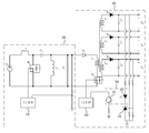
도 2는 일 실시예에 따른 제 2 변환부의 전체적인 구성을 도시한다.
도 3는 다른 실시예에 따른 절연형 멀티 입력 레귤레이터의 전체적인 구성을 도시한다.
도 4는 일 실시예에 따른 제 1 변환부 및 제 2 변환부의 전체적인 구성을 도시한다.
도 5는 다른 실시예에 따른 제 1 변환부 및 제 2 변환부의 전체적인 구성을 도시한다.
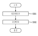
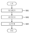
도 6은 일 실시예에 따른 절연형 멀티 입력 레귤레이팅 방법의 전체적인 흐름을 도시한다.
도 7은 다른 실시예에 따른 절연형 멀티 입력 레귤레이팅 방법의 전체적인 흐름을 도시한다.
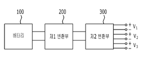
200: 제 1 변환부
300: 제 2 변환부
320: 포토 커플러
321: 수광 소자
322: 발광 소자
330: 가변 정밀 제너 션트 레귤레이터
L1: 제 1 인덕터
M1: 제 1 스위칭 소자
C1: 제 1 커패시터
L2: 제 2 인덕터
D1: 제 1 다이오드
C2: 제 2 커패시터
L3: 제 1 권선
L4: 제 2 권선
L5: 제 3 권선
L6: 제 4 권선
D2: 제 2 다이오드
D3: 제 3 다이오드
D4: 제 4 다이오드
C3: 제 3 커패시터
C4: 제 4 커패시터
C5: 제 5 커패시터
Claims (9)
- 전압을 입력받아 서로 다른 크기를 가지는기설정된 범위의 전압을 출력하는 배터리로부터 전압을 입력받아 서로 다른 크기를 가지는 3개의 출력 전압으로 변환하여 3개의 출력단으로 출력하는 제 2 변환부;를 포함하되,
상기 제 2 변환부는 3개의 출력단 중 적어도 2개의 출력단에서 출력되는 전압에 기초하여 피드백 전압을 입력받고,
상기 적어도 2개의 출력단 중 하나는 출력 전압이 가장 높은 출력단이고, 다른 하나는 부하에 연속적으로 전압을 공급하는 출력단인
절연형 멀티 입력 레귤레이터
- 제 1 항에 있어서,
상기 적어도 2개의 출력단과 기준단자가 연결되는 가변 정밀 제너 션트 레귤레이터; 및
상기 가변 정밀 제너 션트 레귤레이터에 기준 전압 이상의 전압이 인가되면 상기 제 2 변환부로 피드백 전압을 공급하는 포토 커플러;를 포함하는
절연형 멀티 입력 레귤레이터
- 제 1 항에 있어서,
기설정된 범위의 전압을 입력받아 제 1 전압으로 변환하여 상기 제 2 변환부로 출력하는 제 1 변환부;를 더 포함하는,
절연형 멀티 입력 레귤레이터
- 제 3 항에 있어서,
상기 제 1 변환부 및 상기 제 2 변환부는 상기 제 2 변환부의 출력단에 연결된 포토 커플러가 출력하는 피드백 전압을 입력받거나,
상기 제 1 변환부는 상기 제 1 변환부의 출력 전압을 피드백 전압으로 입력 받고,
상기 제 2 변환부는 상기 제 2 변환부의 출력단에 연결된 포토 커플러가 출력하는 피드백 전압을 입력받는 것을 특징으로 하는
절연형 멀티 입력 레귤레이터
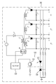
- 제 3 항에 있어서, 상기 제 1 변환부는,
제 1 인덕터;
상기 제 1 인덕터와 일단이 연결되는 제 1 스위칭 소자;
상기 제 1 스위칭 소자를 제어하는 제 1 제어부;
상기 제 1 스위칭 소자의 일단과 연결되는 제 1 커패시터;
상기 제 1 커패시터와 일단이 연결되는 제 2 인덕터;
상기 제 2 인덕터와 에노드가 연결되는 제 1 다이오드; 및
상기 제 1 다이오드와 일단이 연결되는 제 2 커패시터;를 포함하는,
절연형 멀티 입력 레귤레이터.
- 제 1 항에 있어서, 상기 제 2 변환부는
제 1 권선;
상기 제 1 권선과 일단이 연결된 제 2 스위칭 소자;
상기 제 2 스위칭 소자를 제어하는 제 2 제어부;
상기 제 1 권선과 커플링 된 제 2 권선;
상기 제 2 권선과 에노드가 연결되는 제 2 다이오드;
상기 제 2 다이오드와 일단이 연결되는 제 3 커패시터;
상기 제 1 권선과 커플링 된 제 3 권선;
상기 제 3 권선과 에노드가 연결되는 제 3 다이오드;
상기 제 3 다이오드와 일단이 연결되는 제 4 커패시터;
상기 제 1 권선과 커플링 된 제 4 권선;
상기 제 4 권선과 에노드가 연결되는 제 4 다이오드;
상기 제 4 다이오드와 일단이 연결되는 제 5 커패시터;
를 포함하는,
절연형 멀티 입력 레귤레이터.
- 제 2 변환부가 기설정된 범위의 전압을 출력하는 배터리로부터 전압을 입력받아 서로 다른 크기를 가지는 3개의 출력 전압으로 변환하여 3개의 출력단으로 출력하는 제 2 변환 단계; 및
상기 제 2 변환부는 3개의 출력단 중 적어도 2개의 출력단에서 출력되는 전압에 기초하여 피드백 전압을 입력받는 피드백 단계;를 포함하되,
상기 적어도 2개의 출력단 중 하나는 출력 전압이 가장 높은 출력단이고, 다른 하나는 부하에 연속적으로 전압을 공급하는 출력단인
절연형 멀티 입력 레귤레이팅 방법.
- 제 7 항에 있어서,
제 1 변환부가 기설정된 범위의 전압을 입력받아 제 1 전압으로 변환하여 상기 제 2 변환부로 출력하는 OI제 1 변환 단계;를 더 포함하는
절연형 멀티 입력 레귤레이팅 방법.
- 제 8 항에 있어서,
상기 피드백 단계는
상기 제 1 변환부 및 상기 2 변환부는 상기 제 2 변환부의 출력단에 연결된 포토 커플러가 출력하는 피드백 전압을 입력받거나,
상기 제 1 변환부는 상기 제 1 변환부의 출력 전압을 피드백 전압으로 입력 받고,
상기 제 2 변환부는 상기 제 2 변환부의 출력단에 연결된 포토 커플러가 출력하는 피드백 전압을 입력받는 것을 특징으로 하는
절연형 멀티 입력 레귤레이팅 방법.
Priority Applications (1)
| Application Number | Priority Date | Filing Date | Title |
|---|---|---|---|
| KR1020170025310A KR102615836B1 (ko) | 2017-02-27 | 2017-02-27 | 절연형 멀티 입력 레귤레이터 및 절연형 멀티 입력 레귤레이팅 방법 |
Applications Claiming Priority (1)
| Application Number | Priority Date | Filing Date | Title |
|---|---|---|---|
| KR1020170025310A KR102615836B1 (ko) | 2017-02-27 | 2017-02-27 | 절연형 멀티 입력 레귤레이터 및 절연형 멀티 입력 레귤레이팅 방법 |
Publications (2)
| Publication Number | Publication Date |
|---|---|
| KR20180098774A true KR20180098774A (ko) | 2018-09-05 |
| KR102615836B1 KR102615836B1 (ko) | 2023-12-19 |
Family
ID=63594254
Family Applications (1)
| Application Number | Title | Priority Date | Filing Date |
|---|---|---|---|
| KR1020170025310A Active KR102615836B1 (ko) | 2017-02-27 | 2017-02-27 | 절연형 멀티 입력 레귤레이터 및 절연형 멀티 입력 레귤레이팅 방법 |
Country Status (1)
| Country | Link |
|---|---|
| KR (1) | KR102615836B1 (ko) |
Cited By (3)
| Publication number | Priority date | Publication date | Assignee | Title |
|---|---|---|---|---|
| KR20200032569A (ko) * | 2018-09-18 | 2020-03-26 | 엘지이노텍 주식회사 | 피드백 회로를 포함하는 전력 변환 장치 |
| CN112636574A (zh) * | 2020-12-30 | 2021-04-09 | 华清瑞达(天津)科技有限公司 | 一种电源输出保护电路 |
| DE102024126866A1 (de) * | 2024-09-19 | 2026-03-19 | sonnen GmbH | Analog-frontend-schaltung für ein batteriesystem |
Citations (4)
| Publication number | Priority date | Publication date | Assignee | Title |
|---|---|---|---|---|
| KR20060106081A (ko) * | 2005-04-06 | 2006-10-12 | 주식회사 엘지화학 | 멀티 직류 출력 전원 시스템 |
| KR20080024321A (ko) * | 2006-09-13 | 2008-03-18 | 삼성에스디아이 주식회사 | 전원 공급 장치, 전원 공급 장치를 포함하는 플라즈마 표시장치 및 이의 스탠바이 전압 생성 방법 |
| KR20080110376A (ko) * | 2007-06-15 | 2008-12-18 | 엘에스전선 주식회사 | 다출력 어댑터 |
| KR20100027528A (ko) * | 2008-09-02 | 2010-03-11 | 페어차일드코리아반도체 주식회사 | 스위치 모드 전력 공급 장치 및 그 구동 방법 |
-
2017
- 2017-02-27 KR KR1020170025310A patent/KR102615836B1/ko active Active
Patent Citations (4)
| Publication number | Priority date | Publication date | Assignee | Title |
|---|---|---|---|---|
| KR20060106081A (ko) * | 2005-04-06 | 2006-10-12 | 주식회사 엘지화학 | 멀티 직류 출력 전원 시스템 |
| KR20080024321A (ko) * | 2006-09-13 | 2008-03-18 | 삼성에스디아이 주식회사 | 전원 공급 장치, 전원 공급 장치를 포함하는 플라즈마 표시장치 및 이의 스탠바이 전압 생성 방법 |
| KR20080110376A (ko) * | 2007-06-15 | 2008-12-18 | 엘에스전선 주식회사 | 다출력 어댑터 |
| KR20100027528A (ko) * | 2008-09-02 | 2010-03-11 | 페어차일드코리아반도체 주식회사 | 스위치 모드 전력 공급 장치 및 그 구동 방법 |
Cited By (3)
| Publication number | Priority date | Publication date | Assignee | Title |
|---|---|---|---|---|
| KR20200032569A (ko) * | 2018-09-18 | 2020-03-26 | 엘지이노텍 주식회사 | 피드백 회로를 포함하는 전력 변환 장치 |
| CN112636574A (zh) * | 2020-12-30 | 2021-04-09 | 华清瑞达(天津)科技有限公司 | 一种电源输出保护电路 |
| DE102024126866A1 (de) * | 2024-09-19 | 2026-03-19 | sonnen GmbH | Analog-frontend-schaltung für ein batteriesystem |
Also Published As
| Publication number | Publication date |
|---|---|
| KR102615836B1 (ko) | 2023-12-19 |
Similar Documents
| Publication | Publication Date | Title |
|---|---|---|
| US11230201B2 (en) | System of charging battery of vehicle and method for controlling the same | |
| KR20170126053A (ko) | 양방향 파워링이 가능한 차량용 충전기, 이를 포함하는 차량 전력 공급 시스템 및 그 제어방법 | |
| US9776518B2 (en) | System with battery charging device and vehicle electrical system power supply stage | |
| KR20200122033A (ko) | 통합형 컨버터 장치 | |
| KR20210156107A (ko) | 차량용 배터리 충전 장치 및 방법 | |
| CN104377791A (zh) | 一种电动车辆的转换装置和方法 | |
| US9193275B2 (en) | In-vehicle charger | |
| KR20150075591A (ko) | 친환경 차량의 저전압 직류 변환 장치를 위한 멀티 전압 출력 제공 장치 및 방법 | |
| KR20160050953A (ko) | 전기 자동차의 전력 변환 장치 | |
| CN110999053A (zh) | 用于向功率开关控制设备供电的可调电源设备 | |
| US5717579A (en) | Power supply unit, more specifically battery charger for electric vehicles and the like | |
| KR102615836B1 (ko) | 절연형 멀티 입력 레귤레이터 및 절연형 멀티 입력 레귤레이팅 방법 | |
| KR102338378B1 (ko) | 차량용 배터리 충전 시스템 | |
| JP6642119B2 (ja) | 充電器 | |
| KR20130117210A (ko) | 차량용 배터리충전시스템 | |
| JP5255094B2 (ja) | Dc−dcコンバータ及びdc−dcコンバータシステム | |
| CN114649949A (zh) | 大容量双向隔离式直流-直流转换器及其控制方法 | |
| CN111231669B (zh) | 车载充电器、电动车辆的供电系统、电动车辆 | |
| KR102227190B1 (ko) | 전기자동차용 탑재형 충전장치 | |
| KR20180123834A (ko) | 전압 감지 장치 | |
| WO2024106382A1 (ja) | 電源装置 | |
| CN107005162A (zh) | 直流电压转换器系统、直流电压供电系统和用于直流电压转换器系统的印刷电路板 | |
| JP4871647B2 (ja) | Dc−dcコンバータ及びdc−dcコンバータシステム | |
| CN209526519U (zh) | 支持以太网供电的电源供应装置 | |
| KR101387239B1 (ko) | 전력 변환 장치 |
Legal Events
| Date | Code | Title | Description |
|---|---|---|---|
| PA0109 | Patent application |
Patent event code: PA01091R01D Comment text: Patent Application Patent event date: 20170227 |
|
| PG1501 | Laying open of application | ||
| A201 | Request for examination | ||
| PA0201 | Request for examination |
Patent event code: PA02012R01D Patent event date: 20220128 Comment text: Request for Examination of Application Patent event code: PA02011R01I Patent event date: 20170227 Comment text: Patent Application |
|
| E902 | Notification of reason for refusal | ||
| PE0902 | Notice of grounds for rejection |
Comment text: Notification of reason for refusal Patent event date: 20230609 Patent event code: PE09021S01D |
|
| E701 | Decision to grant or registration of patent right | ||
| PE0701 | Decision of registration |
Patent event code: PE07011S01D Comment text: Decision to Grant Registration Patent event date: 20231011 |
|
| GRNT | Written decision to grant | ||
| PR0701 | Registration of establishment |
Comment text: Registration of Establishment Patent event date: 20231215 Patent event code: PR07011E01D |
|
| PR1002 | Payment of registration fee |
Payment date: 20231215 End annual number: 3 Start annual number: 1 |
|
| PG1601 | Publication of registration |