KR20180098774A - Isolated multi-input regulator and Isolated Multi-Input Regulating Method - Google Patents
Isolated multi-input regulator and Isolated Multi-Input Regulating Method Download PDFInfo
- Publication number
- KR20180098774A KR20180098774A KR1020170025310A KR20170025310A KR20180098774A KR 20180098774 A KR20180098774 A KR 20180098774A KR 1020170025310 A KR1020170025310 A KR 1020170025310A KR 20170025310 A KR20170025310 A KR 20170025310A KR 20180098774 A KR20180098774 A KR 20180098774A
- Authority
- KR
- South Korea
- Prior art keywords
- voltage
- output
- conversion unit
- winding
- input
- Prior art date
- Legal status (The legal status is an assumption and is not a legal conclusion. Google has not performed a legal analysis and makes no representation as to the accuracy of the status listed.)
- Granted
Links
- 238000000034 method Methods 0.000 title claims abstract description 23
- 230000001105 regulatory effect Effects 0.000 title claims abstract description 16
- 238000006243 chemical reaction Methods 0.000 claims description 97
- 238000004804 winding Methods 0.000 claims description 83
- 239000003990 capacitor Substances 0.000 claims description 33
- 230000001276 controlling effect Effects 0.000 claims description 6
- 238000004891 communication Methods 0.000 abstract description 18
- 230000000694 effects Effects 0.000 description 4
- 238000012986 modification Methods 0.000 description 2
- 230000004048 modification Effects 0.000 description 2
- 230000002123 temporal effect Effects 0.000 description 2
- 230000001131 transforming effect Effects 0.000 description 2
- 230000005540 biological transmission Effects 0.000 description 1
- 238000002485 combustion reaction Methods 0.000 description 1
- 230000005611 electricity Effects 0.000 description 1
- 239000002803 fossil fuel Substances 0.000 description 1
- 230000020169 heat generation Effects 0.000 description 1
- 238000002955 isolation Methods 0.000 description 1
Images


Classifications
-
- H—ELECTRICITY
- H02—GENERATION; CONVERSION OR DISTRIBUTION OF ELECTRIC POWER
- H02M—APPARATUS FOR CONVERSION BETWEEN AC AND AC, BETWEEN AC AND DC, OR BETWEEN DC AND DC, AND FOR USE WITH MAINS OR SIMILAR POWER SUPPLY SYSTEMS; CONVERSION OF DC OR AC INPUT POWER INTO SURGE OUTPUT POWER; CONTROL OR REGULATION THEREOF
- H02M3/00—Conversion of DC power input into DC power output
- H02M3/22—Conversion of DC power input into DC power output with intermediate conversion into AC
- H02M3/24—Conversion of DC power input into DC power output with intermediate conversion into AC by static converters
- H02M3/28—Conversion of DC power input into DC power output with intermediate conversion into AC by static converters using discharge tubes with control electrode or semiconductor devices with control electrode to produce the intermediate AC
- H02M3/285—Single converters with a plurality of output stages connected in parallel
-
- H—ELECTRICITY
- H02—GENERATION; CONVERSION OR DISTRIBUTION OF ELECTRIC POWER
- H02M—APPARATUS FOR CONVERSION BETWEEN AC AND AC, BETWEEN AC AND DC, OR BETWEEN DC AND DC, AND FOR USE WITH MAINS OR SIMILAR POWER SUPPLY SYSTEMS; CONVERSION OF DC OR AC INPUT POWER INTO SURGE OUTPUT POWER; CONTROL OR REGULATION THEREOF
- H02M3/00—Conversion of DC power input into DC power output
- H02M3/22—Conversion of DC power input into DC power output with intermediate conversion into AC
- H02M3/24—Conversion of DC power input into DC power output with intermediate conversion into AC by static converters
- H02M3/28—Conversion of DC power input into DC power output with intermediate conversion into AC by static converters using discharge tubes with control electrode or semiconductor devices with control electrode to produce the intermediate AC
- H02M3/325—Conversion of DC power input into DC power output with intermediate conversion into AC by static converters using discharge tubes with control electrode or semiconductor devices with control electrode to produce the intermediate AC using devices of a triode or a transistor type requiring continuous application of a control signal
- H02M3/335—Conversion of DC power input into DC power output with intermediate conversion into AC by static converters using discharge tubes with control electrode or semiconductor devices with control electrode to produce the intermediate AC using devices of a triode or a transistor type requiring continuous application of a control signal using semiconductor devices only
- H02M3/33538—Conversion of DC power input into DC power output with intermediate conversion into AC by static converters using discharge tubes with control electrode or semiconductor devices with control electrode to produce the intermediate AC using devices of a triode or a transistor type requiring continuous application of a control signal using semiconductor devices only of the forward type
- H02M3/33546—Conversion of DC power input into DC power output with intermediate conversion into AC by static converters using discharge tubes with control electrode or semiconductor devices with control electrode to produce the intermediate AC using devices of a triode or a transistor type requiring continuous application of a control signal using semiconductor devices only of the forward type with automatic control of the output voltage or current
- H02M3/33553—Conversion of DC power input into DC power output with intermediate conversion into AC by static converters using discharge tubes with control electrode or semiconductor devices with control electrode to produce the intermediate AC using devices of a triode or a transistor type requiring continuous application of a control signal using semiconductor devices only of the forward type with automatic control of the output voltage or current with galvanic isolation between input and output of both the power stage and the feedback loop
-
- H02M2001/0003—
Landscapes
- Engineering & Computer Science (AREA)
- Power Engineering (AREA)
- Dc-Dc Converters (AREA)
Abstract
안정적인 전압을 출력하는 절연형 멀티 입력 레귤레이터 및 절연형 멀티 입력 레귤레이팅 방법에 관한 것으로, 자세하게는 3개의 출력단 중 적어도 2개의 출력단으로부터 전압을 피드백 받아 소형차와 대형차의 전원에 구분 없이 전기자동차의 통신 컨트롤러(Communication Controller of Electric Vehicle; EVCC)에서 필요로 하는 안정적인 전압을 공급하는 절연형 멀티 입력 레귤레이터 및 절연형 멀티 입력 레귤레이팅 방법에 관한 것이다.
제안된 발명이 해결하고자 하는 하나의 과제는 배터리가 출력하는 전압의 크기와 무관하게 전기자동차의 통신 컨트롤러에서 필요로 하는 안정적인 전압을 공급하는 것이다.The present invention relates to an insulated multi-input regulator for outputting a stable voltage and an insulated multi-input regulating method. More particularly, the present invention relates to an insulated multi-input regulator that outputs voltage from at least two output terminals out of three output terminals, And more particularly, to an isolated multi-input regulator and an isolated multi-input regulating method for supplying a stable voltage required by a communication controller of an electric vehicle (EVCC).
One challenge to be solved by the proposed invention is to provide a stable voltage required by the communication controller of the electric vehicle regardless of the magnitude of the voltage output by the battery.
Description
안정적인 전압을 출력하는 절연형 멀티 입력 레귤레이터 및 절연형 멀티 입력 레귤레이팅 방법에 관한 것으로, 자세하게는 3개의 출력단 중 적어도 2개의 출력단으로부터 전압을 피드백 받아 소형차와 대형차의 전원에 구분 없이 전기자동차의 통신 컨트롤러(Communication Controller of Electric Vehicle; EVCC)에서 필요로 하는 안정적인 전압을 공급하는 절연형 멀티 입력 레귤레이터 및 절연형 멀티 입력 레귤레이팅 방법에 관한 것이다. The present invention relates to an insulated multi-input regulator for outputting a stable voltage and an insulated multi-input regulating method. More particularly, the present invention relates to an insulated multi-input regulator that outputs voltage from at least two output terminals out of three output terminals, And more particularly, to an isolated multi-input regulator and an isolated multi-input regulating method for supplying a stable voltage required by a communication controller of an electric vehicle (EVCC).
전기자동차는 구동 에너지를 기존의 자동차와 같이 화석 연료의 연소로부터가 아닌 전기에너지로부터 얻는 자동차이다. 따라서, 이러한 전기 자동차는 전기에너지를 배터리에 충전함으로써 구동력을 확보한다.An electric vehicle is an automobile that derives its drive energy from electric energy, not from combustion of fossil fuels like existing vehicles. Therefore, such an electric vehicle secures the driving force by charging electric energy into the battery.
전기 자동차에 장착되는 배터리로부터 전기 자동차의 모터뿐만 아니라 전기자동차의 통신 컨트롤러(Communication Controller of Electric Vehicle; EVCC)에서 필요로 하는 안정적인 전압을 공급할 필요가 있다.It is necessary to supply a stable voltage required by a communication controller of electric vehicles (EVCC) as well as a motor of an electric vehicle from a battery mounted in the electric vehicle.
자동차의 종류, 예를 들어 소형차, 대형차에 따라 배터리가 출력하는 전압은 상이하다. 배터리가 출력하는 전압의 크기와 무관하게 전기자동차의 통신 컨트롤러에서 필요로 하는 안정적인 전압을 공급할 필요가 있다. 즉, 다중 입력을 가지는 표준화된 멀티 입력 레귤레이터가 제안될 필요가 있다.The voltage output by the battery differs depending on the type of automobile, for example, a compact car or a large car. It is necessary to supply a stable voltage required by the electric vehicle communication controller regardless of the magnitude of the voltage outputted from the battery. That is, a standardized multi-input regulator with multiple inputs needs to be proposed.
또한, 멀티 입력 레귤레이터의 입력단과 출력단을 절연시켜서 입력 전원이 불안정한 경우 발생되는 전원 노이즈의 영향을 최소화할 필요가 있다.Further, it is necessary to insulate the input terminal and the output terminal of the multi-input regulator so as to minimize the influence of power source noise generated when the input power source is unstable.
나아가, 3개의 출력단 중 적어도 2개의 출력단으로부터 전압을 피드백 받아 안정적인 전압을 공급할 필요가 있다.Further, it is necessary to supply a stable voltage by feeding back the voltage from at least two output terminals among the three output terminals.
더 나아가, 멀티 입력 레귤레이터는 출력단에 별도의 LDO 레귤레이터 (Low Dropout Regulator)를 구비하지 않음에 따라 인쇄회로기판의 공간을 확보하고 단가를 낮출 필요가 있다.Furthermore, since the multi-input regulator does not have a separate LDO regulator at the output stage, it is necessary to secure the space of the printed circuit board and to reduce the unit cost.
더 나아가, 멀티 입력 레귤레이터는 하나의 컨버터만을 사용하여 인쇄회로기판의 공간을 확보하고 단가를 낮출 필요가 있다.Furthermore, the multi-input regulator needs to use only one converter to secure the space of the printed circuit board and lower the unit cost.
제안된 발명이 해결하고자 하는 하나의 과제는 배터리가 출력하는 전압의 크기와 무관하게 전기자동차의 통신 컨트롤러에서 필요로 하는 안정적인 전압을 공급하는 것이다.One challenge to be solved by the proposed invention is to provide a stable voltage required by the communication controller of the electric vehicle regardless of the magnitude of the voltage output by the battery.
제안된 발명이 해결하고자 하는 하나의 과제는 멀티 입력 레귤레이터의 입력단과 출력단을 절연시켜서 입력 전원이 불안정한 경우 발생되는 전원 노이즈의 영향을 최소화하는 것이다. One of the problems to be solved by the proposed invention is to insulate the input terminal and the output terminal of the multi-input regulator so as to minimize the influence of power source noise generated when the input power is unstable.
제안된 발명이 해결하고자 하는 하나의 과제는 3개의 출력단 중 적어도 2개의 출력단으로부터 전압을 피드백 받아 안정적인 전압을 공급하는 것이다.One of the problems to be solved by the proposed invention is to supply a stable voltage by feeding back voltage from at least two output terminals among the three output terminals.
제안된 발명이 해결하고자 하는 하나의 과제는 멀티 입력 레귤레이터가 출력단에 별도의 LDO 레귤레이터 (Low Dropout Regulator)를 구비하지 않음에 따라 인쇄회로기판의 공간을 확보하고 단가를 낮추는 것이다.One of the problems to be solved by the proposed invention is that the multi-input regulator does not have a separate LDO regulator at the output stage, thereby securing the space of the printed circuit board and lowering the unit cost.
제안된 발명이 해결하고자 하는 하나의 과제는 멀티 입력 레귤레이터가 하나의 컨버터만을 사용하여 인쇄회로기판의 공간을 확보하고 단가를 낮추는 것이다.One challenge for the proposed invention is that the multi-input regulator uses only one converter to secure space on the printed circuit board and lower the unit cost.
한편, 본 발명이 이루고자 하는 기술적 과제는 이상에서 언급한 기술적 과제로 제한되지 않으며, 이하에서 설명할 내용으로부터 통상의 기술자에게 자명한 범위 내에서 다양한 기술적 과제가 포함될 수 있다.It is to be understood that both the foregoing general description and the following detailed description are exemplary and explanatory and are intended to provide further explanation of the invention as claimed.
일 양상에 있어서, 절연형 멀티 입력 레귤레이터는 기설정된 범위의 전압을 출력하는 배터리로부터 전압을 입력받아 서로 다른 크기를 가지는 3개의 출력 전압으로 변환하여 3개의 출력단으로 출력하는 제 2 변환부;를 포함하되, 상기 제 2 변환부는 3개의 출력단 중 적어도 2개의 출력단에서 출력되는 전압에 기초하여 피드백 전압을 입력받는 것을 특징으로 할 수 있다.In one aspect, the isolated multi-input regulator includes a second converter that receives a voltage from a battery that outputs a voltage in a predetermined range, converts the voltage into three output voltages having different sizes, and outputs the output voltage to three output terminals The second conversion unit receives the feedback voltage based on the voltages output from at least two of the three output stages.
다른 양상에 있어서, 상기 적어도 2개의 출력단 중 하나는 출력 전압이 가장 높은 출력단이고, 다른 하나는 부하에 연속적으로 전압을 공급하는 출력단인 것을 특징으로 한다.In another aspect, one of the at least two output stages is an output stage having the highest output voltage, and the other is an output stage that continuously supplies a voltage to the load.
다른 양상에 있어서, 절연형 멀티 입력 레귤레이터는 상기 적어도 2개의 출력단과 기준단자가 연결되는 가변 정밀 제너 션트 레귤레이터; 및 상기 가변 정밀 제너 션트 레귤레이터에 기준 전압 이상의 전압이 인가되면 제 2 변환부로 피드백 전압을 공급하는 포토 커플러;를 포함한다.In another aspect, an isolated multi-input regulator includes: a variable precision zener regulator in which the at least two output terminals and a reference terminal are connected; And an optocoupler that supplies a feedback voltage to the second conversion unit when a voltage equal to or higher than a reference voltage is applied to the variable precision zener regulator.
다른 양상에 있어서, 절연형 멀티 입력 레귤레이터는 기설정된 범위의 전압을 입력받아 제 1 전압으로 변환하여 제 2 변환부로 출력하는 제 1 변환부;를 더 포함한다.In another aspect, the isolated multi-input regulator further includes a first conversion unit that receives a voltage of a predetermined range, converts the voltage into a first voltage, and outputs the first voltage to the second conversion unit.
다른 양상에 있어서, 제 1 변환부 및 제 2 변환부는 제 2 변환부의 출력단에 연결된 포토 커플러가 출력하는 피드백 전압을 입력받는 것을 특징으로 할 수 있다.In another aspect, the first converter and the second converter may receive the feedback voltage output from the photocoupler connected to the output of the second converter.
다른 양상에 있어서, 제 1 변환부는 제 1 변환부의 출력 전압을 피드백 전압으로 입력 받고, 제 2 변환부는 제 2 변환부의 출력단에 연결된 포토 커플러가 출력하는 피드백 전압을 입력받는 것을 특징으로 한다.In another aspect, the first converter receives the output voltage of the first converter as the feedback voltage, and the second converter receives the feedback voltage output from the photo coupler connected to the output of the second converter.
다른 양상에 있어서, 제 1 변환부는, 세픽 컨버터인 것을 특징으로 한다.In another aspect, the first converter is characterized by being a divide converter.
다른 양상에 있어서, 제 1 변환부는, 제 1 인덕터; 제 1 인덕터와 일단이 연결되는 제 1 스위칭 소자; 제 1 스위칭 소자를 제어하는 제 1 제어부; 제 1 스위칭 소자의 일단과 연결되는 제 1 커패시터; 제 1 커패시터와 일단이 연결되는 제 2 인덕터; 제 2 인덕터와 에노드가 연결되는 제 1 다이오드; 및 제 1 다이오드와 일단이 연결되는 제 2 커패시터;를 포함한다.In another aspect, the first conversion unit includes: a first inductor; A first switching device having a first end connected to the first inductor; A first control unit for controlling the first switching device; A first capacitor connected to one end of the first switching device; A second inductor whose one end is connected to the first capacitor; A first diode connected to the second inductor and the node; And a second capacitor whose one end is connected to the first diode.
다른 양상에 있어서, 제 2 변환부는, 플라이백 컨버터인 것을 특징으로 한다.In another aspect, the second converter is a flyback converter.
다른 양상에 있어서, 제 2 변환부는 제 1 권선; 제 1 권선과 일단이 연결된 제 2 스위칭 소자; 제 2 스위칭 소자를 제어하는 제 2 제어부; 제 1 권선과 커플링 된 제 2 권선; 제 2 권선과 에노드가 연결되는 제 2 다이오드; 제 2 다이오드와 일단이 연결되는 제 3 커패시터; 제 1 권선과 커플링 된 제 3 권선;In another aspect, the second conversion unit includes: a first winding; A second switching element connected to the first winding at one end; A second controller for controlling the second switching element; A second winding coupled to the first winding; A second diode having a node connected to the second winding; A third capacitor whose one end is connected to the second diode; A third winding coupled to the first winding;
제 3 권선과 에노드가 연결되는 제 3 다이오드; 제 3 다이오드와 일단이 연결되는 제 4 커패시터; 제 1 권선과 커플링 된 제 4 권선; 제 4 권선과 에노드가 연결되는 제 4 다이오드; 제 4 다이오드와 일단이 연결되는 제 5 커패시터; 를 포함한다.A third diode having a node connected to the third winding; A fourth capacitor whose one end is connected to the third diode; A fourth winding coupled to the first winding; A fourth diode to which a node is connected to a fourth winding; A fifth capacitor whose one end is connected to the fourth diode; .
다른 양상에 있어서, 제 2 변환부가 기설정된 범위의 전압을 출력하는 배터리로부터 전압을 입력받아 서로 다른 크기를 가지는 3개의 출력 전압으로 변환하여 3개의 출력단으로 출력하는 제 2 변환 단계; 및 상기 제 2 변환부는 3개의 출력단 중 적어도 2개의 출력단에서 출력되는 전압에 기초하여 피드백 전압을 입력받는 피드백 단계;를 포함할 수 있다.In another aspect, the second conversion step may include: a second conversion step of converting a voltage of the battery into a third output voltage having a different magnitude and outputting the output voltage to three output stages; And a feedback step of receiving the feedback voltage based on a voltage output from at least two of the three output stages.
다른 양상에 있어서, 상기 피드백 단계는 제 1 변환부 및 제 2 변환부는 제 2 변환부의 출력단에 연결된 포토 커플러가 출력하는 피드백 전압을 입력받는 것을 특징으로 한다.In another aspect of the present invention, in the feedback step, the first and second conversion units receive a feedback voltage output from a photocoupler connected to an output terminal of the second conversion unit.
다른 양상에 있어서, 상기 피드백 단계는 제 1 변환부는 제 1 변환부의 출력 전압을 피드백 전압으로 입력 받고, 제 2 변환부는 제 2 변환부의 출력단에 연결된 포토 커플러가 출력하는 피드백 전압을 입력받는 것을 특징으로 한다.According to another aspect of the present invention, in the feedback step, the first converter receives the output voltage of the first converter as the feedback voltage, and the second converter receives the feedback voltage output from the photo coupler connected to the output of the second converter. do.
제안된 발명은 배터리가 출력하는 전압의 크기와 무관하게 전기자동차의 통신 컨트롤러에서 필요로 하는 안정적인 전압을 공급할 수 있다.The proposed invention can supply a stable voltage required by the communication controller of the electric vehicle regardless of the magnitude of the voltage output by the battery.
제안된 발명은 멀티 입력 레귤레이터의 입력단과 출력단을 절연시켜서 입력 전원이 불안정한 경우 발생되는 전원 노이즈의 영향을 최소화하는 것이다. The proposed invention isolates the input and output stages of a multi-input regulator to minimize the effects of power source noise when the input power source is unstable.
제안된 발명이 해결하고자 하는 하나의 과제는 3개의 출력단 중 적어도 2개의 출력단으로부터 전압을 피드백 받아 안정적인 전압을 공급하는 것이다.One of the problems to be solved by the proposed invention is to supply a stable voltage by feeding back voltage from at least two output terminals among the three output terminals.
제안된 발명은 멀티 입력 레귤레이터가 출력단에 별도의 LDO 레귤레이터 (Low Dropout Regulator)를 구비하지 않음에 따라 인쇄회로기판의 공간을 확보하고 단가를 낮추는 것이다.In the proposed invention, the multi-input regulator does not have a separate LDO regulator at the output stage, thereby securing the space of the printed circuit board and lowering the unit cost.
제안된 발명은 멀티 입력 레귤레이터가 하나의 컨버터만을 사용하여 인쇄회로기판의 공간을 확보하고 단가를 낮추는 것이다.In the proposed invention, the multi-input regulator uses only one converter to secure the space of the printed circuit board and lower the unit cost.
본 발명의 효과는 이상에서 언급한 효과들로 제한되지 않으며, 이하에서 설명할 내용으로부터 통상의 기술자에게 자명한 범위 내에서 다양한 효과들이 포함될 수 있다.The effects of the present invention are not limited to the above-mentioned effects, and various effects can be included within the range that is obvious to a person skilled in the art from the following description.
도 1은 일 실시예에 따른 절연형 멀티 입력 레귤레이터의 전체적인 구성을 도시한다.
도 2는 일 실시예에 따른 제 2 변환부의 전체적인 구성을 도시한다.
도 3는 다른 실시예에 따른 절연형 멀티 입력 레귤레이터의 전체적인 구성을 도시한다.
도 4는 일 실시예에 따른 제 1 변환부 및 제 2 변환부의 전체적인 구성을 도시한다.
도 5는 다른 실시예에 따른 제 1 변환부 및 제 2 변환부의 전체적인 구성을 도시한다.
도 6은 일 실시예에 따른 절연형 멀티 입력 레귤레이팅 방법의 전체적인 흐름을 도시한다.
도 7은 다른 실시예에 따른 절연형 멀티 입력 레귤레이팅 방법의 전체적인 흐름을 도시한다.
1 shows an overall configuration of an isolated multi-input regulator according to an embodiment.
Fig. 2 shows the overall configuration of the second conversion unit according to one embodiment.
3 shows an overall configuration of an insulated multi-input regulator according to another embodiment.
4 shows an overall configuration of a first conversion unit and a second conversion unit according to an embodiment.
5 shows an overall configuration of a first conversion unit and a second conversion unit according to another embodiment.
6 illustrates an overall flow of an isolated multi-input regulating method according to one embodiment.
FIG. 7 shows an overall flow of an isolated multi-input regulating method according to another embodiment.
전술한, 그리고 추가적인 양상들은 첨부된 도면을 참조하여 설명하는 실시예들을 통해 구체화된다. 각 실시예들의 구성 요소들은 다른 언급이나 상호간에 모순이 없는 한 실시예 내에서 다양한 조합이 가능한 것으로 이해된다. 나아가 제안된 발명은 여러 가지 상이한 형태로 구현될 수 있으며 여기에서 설명하는 실시예에 한정되지 않는다. The foregoing and further aspects are embodied through the embodiments described with reference to the accompanying drawings. It is to be understood that the components of each embodiment are capable of various combinations within an embodiment as long as no other mention or mutual contradiction exists. Furthermore, the proposed invention may be embodied in many different forms and is not limited to the embodiments described herein.
도면에서 제안된 발명을 명확하게 설명하기 위해서 설명과 관계없는 부분은 생략하였으며, 명세서 전체를 통하여 유사한 부분에 대해서는 유사한 도면 부호를 붙였다. 그리고, 어떤 부분이 어떤 구성 요소를 "포함"한다고 할 때, 이는 특별히 반대되는 기재가 없는 한 다른 구성 요소를 제외하는 것이 아니라 다른 구성 요소를 더 포함할 수 있는 것을 의미한다. In order to clearly illustrate the claimed invention, parts not related to the description are omitted, and like reference numerals are used for like parts throughout the specification. And, when a section is referred to as "including " an element, it does not exclude other elements unless specifically stated to the contrary.
또한, 명세서 전체에서, 어떤 부분이 다른 부분과 "연결"되어 있다고 할 때, 이는 "직접적으로 연결"되어 있는 경우뿐 아니라, 그 중간에 다른 소자를 사이에 두고 "전기적으로 연결"되어 있는 경우도 포함한다. 나아가, 명세서 전체에서 신호는 전압이나 전류 등의 전기량을 의미한다.In addition, throughout the specification, when a part is referred to as being "connected" to another part, it is not limited to a case where it is "directly connected", but also an "electrically connected" . Further, in the specification, a signal means a quantity of electricity such as a voltage or a current.
명세서에서 기술한 부란, "하드웨어 또는 소프트웨어의 시스템을 변경이나 플러그인 가능하도록 구성한 블록"을 의미하는 것으로서, 즉 하드웨어나 소프트웨어에 있어 특정 기능을 수행하는 하나의 단위 또는 블록을 의미한다.As used herein, the term " block " refers to a block of hardware or software configured to be changed or pluggable, i.e., a unit or block that performs a specific function in hardware or software.
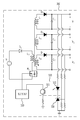
도 1은 일 실시예에 따른 절연형 멀티 입력 레귤레이터의 전체적인 구성을 도시한다. 1 shows an overall configuration of an isolated multi-input regulator according to an embodiment.
절연형 멀티 입력 레귤레이터는 넓은 입력 범위에서 동작한다. 입력 범위는 예를 들어 2~40V이다. 절연형 멀티 입력 레귤레이터는 전기 자동차(Electric Vehicle; EV)에 구비될 수 있다. 자세하게, 절연형 멀티 입력 레귤레이터는 전기자동차의 통신 컨트롤러(Communication Controller of Electric Vehicle; EVCC)에 구비되어, 통신 컨트롤러가 포함하는 캔(Controller Area Network, CAN) 전송기에 필요로 하는 전압을 공급한다. 이에 한정되는 것은 아니고, 통신 컨트롤러에 포함된 마이크로 컨트롤러 유닛(Micro controller unit; MCU)의 메인 전압 또는 마이크로 컨트롤럴 유닛의 코어 전압을 공급한다.Isolated multi-input regulators operate over a wide input range. The input range is, for example, 2 to 40 V. An isolated multi-input regulator may be provided in an electric vehicle (EV). In detail, an insulated multi-input regulator is provided in a communication controller of an electric vehicle (EVCC) to supply a voltage required for a CAN (Controller Area Network) transmitter included in a communication controller. But is not limited to this, and supplies the main voltage of the micro controller unit (MCU) included in the communication controller or the core voltage of the microcontroller unit.
마이크로 컨트롤러 유닛은 마이크로프로세서와 입출력 모듈을 하나의 칩으로 만들어 정해진 기능을 수행하는 컴퓨터를 의미한다. 마이크로컨트롤러가 자동차에 사용되는 경우 ECU(Electronic control unit)라는 장치로 구현될 수 있으며, 자동차의 엔진, 자동 변속기, ABS 의 다양한 부품을 컴퓨터로 제어하도록 한다. A microcontroller unit refers to a computer that makes a microprocessor and an input / output module into one chip and performs predetermined functions. When a microcontroller is used in an automobile, it can be implemented as an electronic control unit (ECU), and various components of an automobile engine, an automatic transmission and an ABS are controlled by a computer.
도 2는 일 실시예에 따른 제 2 변환부(300)의 전체적인 구성을 도시한다.FIG. 2 shows the overall configuration of the
일 실시예에 있어서, 절연형 멀티 입력 레귤레이터는 기설정된 범위의 전압을 출력하는 배터리로부터 전압을 입력받아 서로 다른 크기를 가지는 3개의 출력 전압으로 변환하여 3개의 출력단으로 출력하는 제 2 변환부(300);를 포함하되, 상기 제 2 변환부(300)는 3개의 출력단 중 적어도 2개의 출력단에서 출력되는 전압에 기초하여 피드백 전압을 입력받는 것을 특징으로 한다.In one embodiment, the insulated multi-input regulator includes a
배터리는 전기 자동차에 구비되어 전기 자동차 충전 설비 (Electric Vehicle Supply Equipment, EVSE)로부터 충전될 수 있다. 배터리의 충전을 위해, 전기 자동차 충전 설비에 연결된 충전 케이블이 전기 자동차의 주입구에 연결될 수 있다.The battery may be provided in an electric vehicle and charged from an Electric Vehicle Supply Equipment (EVSE). To charge the battery, a charging cable connected to the electric vehicle charging facility may be connected to the inlet of the electric vehicle.
전기 자동차가 충전을 위하여 전기 자동차 충전 설비와 연결되는 경우, 전기 자동차가 포함하는 전기자동차의 통신 컨트롤러를 통하여 배터리에 전기에너지를 충전하게 된다. When the electric vehicle is connected to an electric vehicle charging facility for charging, electric energy is charged to the battery through a communication controller of the electric vehicle included in the electric vehicle.
여기서, 전기 자동차 충전 설비는 AC 또는 DC를 공급하는 설비이며, 충전소에 배치되거나, 가정 내에 배치될 수 있으며, 휴대 가능하도록 구현될 수도 있다. Here, the electric vehicle charging facility is a facility for supplying AC or DC, and may be disposed in a charging station, placed in a home, or portable.
한편, 전기 자동차와 전기 자동차 충전 설비는 여러 가지 방법으로 연결될 수 있다. 먼저, 전기 자동차와 전기 자동차 충전 설비는 충전 케이블을 이용하여 연결되며, 충전 케이블의 플러그는 전기 자동차에 영구적으로 장착될 수 있다. 이때, 충전 케이블은 가정용 또는 산업용 소켓-아웃렛에 연결되거나, 충전소에 연결될 수 있다.On the other hand, electric vehicles and electric vehicle charging facilities can be connected in various ways. First, the electric vehicle and the electric vehicle charging facility are connected using a charging cable, and the plug of the charging cable can be permanently mounted on the electric vehicle. At this time, the charging cable may be connected to a socket for domestic or industrial use or to a charging station.
또한, 전기 자동차와 전기 자동차 충전 설비는 탈착 가능한(detachable) 충전 케이블을 이용하여 연결되며, 충전 케이블은 차량측 커넥터와 전기 자동차 충전 설비측 플러그, 즉 벽에 고정된 소켓-아웃렛측 또는 충전소측 커넥터를 포함할 수 있다.In addition, the electric vehicle and electric vehicle charging equipment are connected using a detachable charging cable, and the charging cable is connected to the vehicle-side connector and the electric vehicle charging equipment-side plug, that is, the socket-outlet side or the charging- . ≪ / RTI >
아울러, 전기 자동차와 전기 자동차 충전 설비는 충전 케이블을 이용하여 연결되며, 충전 케이블은 충전소에 영구적으로 장착될 수 있다.In addition, electric vehicles and electric vehicle charging facilities are connected using a charging cable, and the charging cable can be permanently attached to the charging station.
배터리는 배터리 관리 시스템(Battery Management System, BMS)을 포함하는 것을 의미할 수 있다. 이때, 배터리 관리 시스템은 마이크로 컨트롤러 유닛과 연결되어 전기 자동차 충전 설비로부터 전달되는 전원을 배터리에 연결하고, 충전을 컨트롤할 수 있다. 또는, 배터리 관리 시스템은 배터리의 충전 개시 여부를 판단하거나, 마이크로 컨트롤러 유닛에게 배터리의 소모량을 전송할 수도 있다.The battery may be meant to include a battery management system (BMS). At this time, the battery management system can be connected to the microcontroller unit to connect the power supplied from the electric vehicle charging equipment to the battery and to control the charging. Alternatively, the battery management system may determine whether to start charging the battery, or may transmit the consumption amount of the battery to the microcontroller unit.
일 실시예에 있어서, 제 2 변환부(300)는 기설정된 범위의 전압을 출력하는 배터리로부터 전압을 입력받아 서로 다른 크기를 가지는 3개의 출력 전압으로 변환하여 3개의 출력단으로 출력한다. 제 2 변환부(300)는 배터리(100)로부터 전압을 입력받는다. In one embodiment, the
배터리(100)는 기설정된 범위의 전압을 출력한다 기설정된 범위의 전압은 예를 들어 2~40V이다. 이에 한정되는 것은 아니고 6~36V이다. 전술한 기설정된 범위의 전압은 전기 자동차가 포함하는 배터리(100)가 공급하는 전압이다.The
기설정된 범위의 전압을 입력받는 다는 것은 고정된 직류 전압을 입력 받되, 상기 고정된 직류 전압의 크기는 기설정된 범위내에 있음을 의미한다. 이에 한정되는 것은 아니고, 제 2 변환부(300)는 교류 전압을 공급 받을 수도 있다.Receiving a predetermined range of voltage means that a fixed DC voltage is input, and the magnitude of the fixed DC voltage is within a predetermined range. The present invention is not limited thereto, and the
제 2 변환부(300)는 입력단과 출력단이 절연되어 있는 것을 특징으로 한다.The
제 2 변환부(300)는 서로 다른 크기를 가지는 3개의 출력 전압을 3개의 출력단으로 출력한다. 3개의 출력단에서 출력되는 전압은 도 1 또는 도 2에 도시된 V1, V2, V3이다. 제 2 변환부(300)의 제 1 권선(L3)과 커플링된 권선은 제 2 권선(L4), 제 3 권선(L5), 제 4 권선(L6)이다.The
제 1 권선(L3)과 제 2 권선(L4)의 권선비에 따라 입력 전압과 다른 크기의 출력 전압 V1이 출력된다. 제 1 권선(L3)과 제 3 권선(L5)의 권선비에 따라 입력 전압과 다른 크기의 출력 전압 V2이 출력된다. 제 1 권선(L3)과 제 3 권선(L5)의 권선비에 따라 입력 전압과 다른 크기의 출력 전압 V3이 출력된다.An output voltage V1 having a magnitude different from the input voltage is output according to the turns ratio of the first winding L3 and the second winding L4. An output voltage V2 having a magnitude different from the input voltage is output according to the turns ratio of the first winding L3 and the third winding L5. An output voltage V3 having a magnitude different from that of the input voltage is output according to the turns ratio of the first winding L3 and the third winding L5.
제 2 변환부(300)의 어느 하나의 출력단은 통신 컨트롤러가 포함하는 캔(Controller Area Network, CAN) 전송기와 연결되어 5V를 공급할 수 있다.Any one of the output terminals of the
제 2 변환부(300)의 다른 하나의 출력단은 마이크로 컨트롤러 유닛과 연결되어 마이크로 컨트롤러 유닛 메인 전압인 3.3V를 공급할 수 있다.The other output terminal of the
제 2 변환부(300)의 또 다른 하나의 출력단은 마이크로 컨트롤러 유닛과 연결되어 마이크로 컨트롤러 유닛 코어 전압인 1.3V를 공급할 수 있다.Another output terminal of the
제 2 스위칭 소자의 온/오프에 따라 제 2 변환부(300)의 제 1 권선(L3)에 전류가 흐르거나 흐르지 않는다. 제 2 스위칭 소자는 도 2에 도시된 것 처럼 모스펫(MOSFET)일 수 있다. 이에 한정되는 것은 아니고, 양극성 접합 트랜지스터(Bipolar Junction Transistor, BJT) 등 다른 스위칭 소자일 수 있다.Current does not flow or flows in the first winding (L3) of the second converter (300) in accordance with the on / off state of the second switching element. The second switching device may be a MOSFET (MOSFET) as shown in Fig. But the present invention is not limited thereto, and may be other switching devices such as a bipolar junction transistor (BJT).
제 2 제어부는 상기 제 2 스위칭 소자의 온/오프를 제어한다.The second control unit controls on / off of the second switching device.
일 실시예에 있어서, 상기 제 2 변환부(300)는 3개의 출력단 중 적어도 2개의 출력단에서 출력되는 전압에 기초하여 피드백 전압을 입력받는 것을 특징으로 한다. 상기 제 2 변환부(300)는 3개의 출력단 모두에서 출력되는 전압에 기초하여 피드백 전압을 입력받는 것을 특징으로 할 수도 있다.In one embodiment, the
제 2 변환부(300)가 포함하는 제 2 제어부는 3개의 출력 단 중 적어도 2개의 출력단에서 출력되는 전압에 기초하여 피드백 전압을 입력 받는다.The second control unit included in the
제 2 제어부는 3개의 출력 단 중 적어도 2개의 출력단에서 출력되는 전압을 피드백 받아 제 2 스위칭부의 온/오프를 제어한다.The second control unit controls the on / off state of the second switching unit by receiving the voltage output from at least two of the three output stages.
일 실시예에 있어서, 상기 적어도 2개의 출력단 중 하나는 출력 전압이 가장 높은 출력단이고, 다른 하나는 부하에 연속적으로 전압을 공급하는 출력단인 것을 특징으로 한다.In one embodiment, one of the at least two output terminals is an output terminal with the highest output voltage, and the other is an output terminal that continuously supplies a voltage to the load.
출력 전압이 가장 높은 출력단은 통신 컨트롤러가 포함하는 캔 전송기와 연결된 출력단이다.The output terminal with the highest output voltage is the output terminal connected to the CAN transmitter included in the communication controller.
출력 전압이 가장 높은 출력단이 출력하는 전압을 제 2 변환부(300)가 피드백 받음에 따라, 더 정밀하게 제 2 스위칭 소자를 제어할 수 있다. 출력 전압의 크기가 크면 출력 전압의 최대값과 최소값의 차이도 커지게 되어 제 2 변환부(300)는 세밀한 피드백을 받을 수 있다.The
연속적으로 전압을 공급하는 출력단은 마이크로 컨트롤러 유닛과 연결되어 마이크로 컨트롤러 유닛 코어 전압을 공급하는 출력단이다.An output terminal for supplying a continuous voltage is an output terminal connected to the microcontroller unit to supply a microcontroller unit core voltage.
연속적으로 전압을 공급하는 출력단이 출력하는 전압을 제 2 변환부(300)가 피드백 받음에 따라, 시간적인 공백 없이 연속적으로 현재 출력 전압에 기초하여 제 2 스위칭 소자를 제어할 수 있다. The second switching unit can be continuously controlled based on the current output voltage without temporal blanking as the second converting
일 실시예에 있어서, 상기 제 2 변환부(300)는, 입력 전압과 동일한 크기를 가지는 전압을 출력하는 것을 특징으로 한다.In one embodiment, the
즉, 제 2 변환부(300)의 3개의 출력단 중 어느 하나의 출력단은 입력 전압과 동일한 크기를 가지는 전압을 출력한다.That is, one of the three output terminals of the
제 2 변환부(300)는 예를 들어 배터리(100)가 공급하는 전압인 5V와 동일한 제 2 전압인 5V를 출력할 수 있다. 이에 한정되는 것은 아니고 입력 전압의 크기와 상관없이 입력 전압의 크기와 동일한 출력 전압을 출력할 수 있다.The
제 2 변환부(300)가 포함하는 제 2 스위칭 소자의 온 오프 듀티비가 50:50인 경우, 제 2 변환부(300)는 제 1 전압의 크기와 상관없이 제 1 전압의 크기와 동일한 제 2 전압을 출력할 수 있다.If the on / off duty ratio of the second switching device included in the
제 2 변환부(300)가 포함하는 제 2 스위칭 소자의 온 오프 듀티비가 50:50인 경우, 온의 비율이 높은 경우 보다 제 2 스위칭 소자의 동작 시간이 줄어들어 발열로 인한 손실이 줄어든다.When the on-off duty ratio of the second switching device included in the
제 2 변환부(300)가 포함하는 제 2 스위칭 소자의 온 오프 듀티비가 50:50인 경우, 온의 비율이 낮은 경우 보다 제 2 변환부(300)가 출력하는 전류 피크치가 높지 않고, 스위칭 손실이 줄어들어 전력 소모가 줄어든다.When the on-off duty ratio of the second switching element included in the
일 실시예에 있어서, 절연형 멀티 입력 레귤레이터는 상기 적어도 2개의 출력단과 기준단자가 연결되는 가변 정밀 제너 션트 레귤레이터(330))(Adjustable Precision Zener Shunt Regulator); 및 상기 가변 정밀 제너 션트 레귤레이터(330)에 기준 전압 이상의 전압이 인가되면 제 2 변환부(300)로 피드백 전압을 공급하는 포토 커플러(320);를 포함한다.In one embodiment, the isolated multi-input regulator includes an adjustable precision
일 실시예에 있어서, 가변 정밀 제너 션트 레귤레이터(330)는 상기 적어도 2개의 출력단과 기준단자가 연결된다. 도 2에 따르면 가변 정밀 제너 션트 레귤레이터(330)의 기준단자는 제 2 권선(L4)과 연결된 출력단 및 제 4 권선(L6)과 연결된 출력단과 연결된다.In one embodiment, the variable
가변 정밀 제너 션트 레귤레이터(330)는 제 2 권선(L4)과 연결된 출력단이 출력하는 전압이 2개의 저항의 분배비가 곱해진 전압이 인가된다.The variable
가변 정밀 제너 션트 레귤레이터(330)는 제 4 권선(L6)과 연결된 출력단이 출력하는 전압이 2개의 저항의 분배비가 곱해진 전압이 인가된다.In the variable
제 2 권선(L4)과 연결된 출력단이 출력하는 전압이 2개의 저항의 분배비가 곱해진 전압과 제 4 권선(L6)과 연결된 출력단이 출력하는 전압이 2개의 저항의 분배비가 곱해진 전압이 동일해 지도록 하는 저항 4개가 사용된다.The voltage output by the output terminal connected to the second winding L4 is multiplied by the distribution ratio of the two resistors and the voltage output by the output terminal connected to the fourth winding L6 is equal to the voltage obtained by multiplying the distribution ratio of the two resistors Four resistors are used.
일 실시예에 있어서, 포토 커플러(320)는 상기 가변 정밀 제너 션트 레귤레이터(330)에 기준 전압 이상의 전압이 인가되면 제 2 변환부(300)로 피드백 전압을 공급한다. 포토 커플러(320)는 발광 소자(322) 및 수광 소자(321)를 포함한다.In one embodiment, the
포토 커플러(320)의 발광 소자(322)와 연결된 가변 정밀 제너 션트 레귤레이터(330)(Adjustable Precision Zener Shunt Regulator)에 기준 이상의 전압이 인가되면 포토 커플러(320)가 포함하는 발광 소자(322)에 전류가 흐름에 따라 발광 소자(322)는 발광한다. 발광 소자(322)가 발광함에 따라 수광 소자(321)는 온되어 제 1 변환부(200) 및 제 2 변환부(300)로 피드백 전압이 공급된다.When a voltage equal to or higher than a reference voltage is applied to the variable precision
도 2에 따르면, 발광 소자(322)의 일단은 제 2 권선(L4)과 연결된 출력단에 연결된다. 이에 한정되는 것은 아니고, 발광 소자(322)의 일단은 제 3권선과 연결되 출력단 또는 제 4권선과 연결된 출력단에 연결될 수 있다.2, one end of the
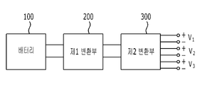
도 3는 다른 실시예에 따른 절연형 멀티 입력 레귤레이터의 전체적인 구성을 도시한다.3 shows an overall configuration of an insulated multi-input regulator according to another embodiment.
일 실시예에 있어서, 절연형 멀티 입력 레귤레이터는 기설정된 범위의 전압을 입력받아 제 1 전압으로 변환하여 제 2 변환부(300)로 출력하는 제 1 변환부(200);를 더 포함한다. 기설정된 범위의 전압은 예를 들어 2~40V이다. 이에 한정되는 것은 아니고 6~36V이다. 전술한 기설정된 범위의 전압은 전기 자동차가 포함하는 배터리(100)가 공급하는 전압이다.In one embodiment, the isolation type multi-input regulator further includes a
기설정된 범위의 전압을 입력받는 다는 것은 고정된 직류 전압을 입력 받되, 상기 고정된 직류 전압의 크기는 기설정된 범위내에 있음을 의미한다.Receiving a predetermined range of voltage means that a fixed DC voltage is input, and the magnitude of the fixed DC voltage is within a predetermined range.
제 1 변환부(200)는 기설정된 범위의 전압을 입력 받아 12V의 전압으로 변환하여 출력한다. 이에 한정되는 것은 아니고, 제 1 변환부(200)는 2~40V 범위에 있는 직류 전압을 출력할 수 있다.The
도 4는 일 실시예에 따른 제 1 변환부(200) 및 제 2 변환부(300)의 전체적인 구성을 도시한다.4 illustrates the overall configuration of the
일 실시예에 있어서, 제 1 변환부(200) 및 제 2 변환부(300)는 제 2 변환부(300)의 출력단에 연결된 포토 커플러(320)가 출력하는 피드백 전압을 입력받는 것을 특징으로 한다.The
제 1 변환부(200) 및 제 2 변환부(300)는 제 2 변환부(300)의 출력단에 연결된 포토 커플러(320)가 출력하는 피드백 전압을 통해 단일 피드백을 받는다.The
제 2 변환부(300)의 포토 커플러(320)의 발광 소자(322)와 연결된 가변 정밀 제너 션트 레귤레이터(330)(Adjustable Precision Zener Shunt Regulator)에 기준 이상의 전압이 인가되면 포토 커플러(320)가 포함하는 발광 소자(322)에 전류가 흐름에 따라 발광 소자(322)는 발광한다. 발광 소자(322)가 발광함에 따라 수광 소자(321)는 온되어 제 1 변환부(200) 및 제 2 변환부(300)로 피드백 전압이 공급된다.When a voltage equal to or higher than a reference voltage is applied to the variable precision
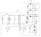
도 5는 다른 실시예에 따른 제 1 변환부(200) 및 제 2 변환부(300)의 전체적인 구성을 도시한다.5 shows the overall configuration of the
일 실시예에 있어서, 제 1 변환부(200)는 제 1 변환부(200)의 출력 전압을 피드백 전압으로 입력 받고, 제 2 변환부(300)는 제 2 변환부(300)의 출력단에 연결된 포토 커플러(320)가 출력하는 피드백 전압을 입력받는 것을 특징으로한다.The
제 1 변환부(200) 및 제 2 변환부(300)는 각각 상이한 피드백 전압을 입력 받는다.The
제 1 변환부(200)는 제 1 변환부(200)의 출력단에 직렬 연결된 2개의 저항 중 접지에 연결된 저항의 크기에 비례하여 피드백 전압을 입력받는다.The
제 2 변환부(300)의 포토 커플러(320)의 발광 소자(322)와 연결된 가변 정밀 제너 션트 레귤레이터(330)(Adjustable Precision Zener Shunt Regulator)에 기준 이상의 전압이 인가되면 포토 커플러(320)가 포함하는 발광 소자(322)에 전류가 흐름에 따라 발광 소자(322)는 발광한다. 발광 소자(322)가 발광함에 따라 수광 소자(321)는 온되어 제 2 변환부(300)로 피드백 전압이 공급된다.When a voltage equal to or higher than a reference voltage is applied to the variable precision
일 실시예에 있어서, 제 1 변환부(200)는, 세픽 컨버터인 것을 특징으로 한다.In one embodiment, the
세픽 컨버터는 입력 단과 출력 단에 각각 인덕터를 구비함으로써 입력 및 출력 측의 전류 리플 (Current Ripple)이 적다. 세픽 컨버터의 출력 전압이 입력 전압보다 높거나 낮을 수 있는 특징을 지님으로서 역률 개선 (Power Factor Correction)과 전압 조절 장치(Voltage Regulator Module)로 이용될 수 있다.The ripple currents at the input and output sides are small because the inductor is provided at the input and output stages, respectively. The output voltage of the divide converter can be higher or lower than the input voltage and can be used as a power factor correction and a voltage regulator module.
일 실시예에 있어서, 제 1 변환부(200)는, 제 1 인덕터(L1); 제 1 인덕터(L1)와 일단이 연결되는 제 1 스위칭 소자(M1); 제 1 스위칭 소자(M1)를 제어하는 제 1 제어부; 제 1 스위칭 소자(M1)의 일단과 연결되는 제 1 커패시터(C1); 제 1 커패시터(C1)와 일단이 연결되는 제 2 인덕터(L2); 제 2 인덕터(L2)와 에노드가 연결되는 제 1 다이오드(D1); 및 제 1 다이오드(D1)와 일단이 연결되는 제 2 커패시터(C2);를 포함한다.In one embodiment, the
제 1 제어부는 제 1 스위칭 소자(M1)의 게이트단과 연결되어 제 1 스위칭 소자(M1)를 온오프 시킨다.The first control unit is connected to the gate of the first switching device M1 to turn on / off the first switching device M1.
제 1 스위칭 소자(M1)가 ON 상태이면 제 1 인덕터(L1)는 입력 전압에 의해 충전된다. 제 1 스위칭 소자(M1)가 ON 상태이면, 제 2 인덕터(L2)는 충전되어 있던 제 1 커패시터(C1)에 의해 충전된다. 제 1 스위칭 소자(M1)가 ON 상태이면, 제 3 커패시터(C3)(C3)에 의해 부하 전류가 공급된다. When the first switching device M1 is in the ON state, the first inductor L1 is charged by the input voltage. When the first switching device M1 is in the ON state, the second inductor L2 is charged by the first capacitor C1 that has been charged. When the first switching device M1 is in the ON state, the load current is supplied by the third capacitors C3 and C3.
제 1 스위칭 소자(M1)가 ON 상태이면, 제 1 인덕터(L1)의 전압은 입력 전압과 같고, 제 2 인덕터(L2)의 전압은 제 1 커패시터(C1) 전압과 동일하다.When the first switching device M1 is in the ON state, the voltage of the first inductor L1 is equal to the input voltage, and the voltage of the second inductor L2 is equal to the voltage of the first capacitor C1.
제 1 스위칭 소자(M1)가 OFF 상태이면, 제 1 인덕터(L1)와 제 2 인덕터(L2)는 방전된다.When the first switching device M1 is in the OFF state, the first inductor L1 and the second inductor L2 are discharged.
제 1 스위칭 소자(M1)가 OFF 상태이면, 제 1 인덕터(L1)가 출력하는 전류는 제 1 커패시터(C1) 및 제 2 커패시터(C2)를 충전시키고, 출력단으로 흐른다. 제 1 스위칭 소자(M1)가 OFF 상태이면, 제 2 인덕터(L2)가 출력하는 전류는 제 2 커패시터(C2)를 충전시키고 출력단으로 흐른다. When the first switching device M1 is in the OFF state, the current output from the first inductor L1 charges the first capacitor C1 and the second capacitor C2 and flows to the output terminal. When the first switching device M1 is in the OFF state, the current output from the second inductor L2 charges the second capacitor C2 and flows to the output terminal.
제 1 스위칭 소자(M1)가 OFF 상태이면, 제 1 인덕터(L1)의 전압은 입력전압-제 1 커패시터(C1) 전압- 출력전압이다. 제 1 스위칭 소자(M1)가 OFF 상태이면, 제 2 인덕터(L2)의 전압은 출력 전압과 같다.When the first switching device M1 is in the OFF state, the voltage of the first inductor L1 is the input voltage-the first capacitor C1 voltage-output voltage. When the first switching device M1 is in the OFF state, the voltage of the second inductor L2 is equal to the output voltage.
제 1 변환부(200)의 제 1 제어부는 제 1 스위칭 소자(M1)의 온 오프 듀티비를 조절하여, 제 1 변환부(200)가 입력 전압에 상관없이 의도한 출력 전압을 출력할 수 있도록 한다.The first control unit of the
일 실시예에 있어서, 제 2 변환부(300)는 플라이백 컨버터인 것을 특징으로 한다.In one embodiment, the
일 실시예에 있어서, 제 2 변환부(300)는 제 1 권선(L3); 제 1 권선(L3)과 일단이 연결된 제 2 스위칭 소자; 제 2 스위칭 소자를 제어하는 제 2 제어부; 제 1 권선(L3)과 커플링 된 제 2 권선(L4); 제 2 권선(L4)과 에노드가 연결되는 제 2 다이오드(D2); 제 2 다이오드(D2)와 일단이 연결되는 제 3 커패시터(C3); 제 1 권선(L3)과 커플링 된 제 3 권선(L5);In one embodiment, the
제 3 권선(L5)과 에노드가 연결되는 제 3 다이오드(D3); 제 3 다이오드(D3)와 일단이 연결되는 제 4 커패시터(C4); 제 1 권선(L3)과 커플링 된 제 4 권선(L6); 제 4 권선(L6)과 에노드가 연결되는 제 4 다이오드(D4); 제 4 다이오드(D4)와 일단이 연결되는 제 5 커패시터(C5); 를 포함한다.A third diode D3 to which the third winding L5 and the node are connected; A fourth capacitor C4 having one end connected to the third diode D3; A fourth winding L6 coupled with the first winding L3; A fourth diode D4 to which the fourth winding L6 and the node are connected; A fifth capacitor C5 whose one end is connected to the fourth diode D4; .
제 2 제어부는 제 2 스위칭 소자의 게이트단과 연결되어 제 2 스위칭 소자를 온오프 시킨다.The second control unit is connected to the gate terminal of the second switching element to turn on / off the second switching element.
제 2 스위칭 소자가 ON 상태이면, 제 1 권선(L3)의 양단 전압은 제 2 변환부(300)의 입력 전압과 같아진다. 제 2 스위칭 소자가 ON 상태이면 제 1 권선(L3)에는 에너지가 저장된다. 제 2 스위칭 소자가 ON 상태이면, 제 2 다이오드(D2), 제 3 다이오드(D3) 및 제 4 다이오드(D4)에 역전압이 인가되어 제 2 권선(L4), 제 3 권선(L5) 및 제 4 권선(L6)에는 전류가 흐르지 못한다.When the second switching element is in the ON state, the voltage across the first winding L3 becomes equal to the input voltage of the
제 2 스위칭 소자가 OFF 상태이면, 제 1 권선(L3)을 포함하는 1차측 회로는 개방되어 제 1 권선(L3)에 전류가 흐르지 못한다. 제 2 권선(L4)에는 역기전력이 발생하여 제 2 다이오드(D2)를 도통시킨다. 제 2 권선(L4)이 출력하는 전류는 제 2 다이오드(D2)를 통해 제 3 캐패시터 및 부하로 흐른다.When the second switching element is in the OFF state, the primary side circuit including the first winding L3 is opened and no current flows through the first winding L3. A counter electromotive force is generated in the second winding L4 to turn on the second diode D2. The current output by the second winding L4 flows to the third capacitor and the load through the second diode D2.
제 3 권선(L5)에는 역기전력이 발생하여 제 3 다이오드(D3)를 도통시킨다. 제 3 권선(L5)이 출력하는 전류는 제 2 다이오드(D2)를 통해 제 4 캐패시터 및 부하로 흐른다.A counter electromotive force is generated in the third winding L5 to turn on the third diode D3. The current output by the third winding L5 flows through the second diode D2 to the fourth capacitor and the load.
제 4 권선(L6)에는 역기전력이 발생하여 제 4 다이오드(D4)를 도통시킨다. 제 4 권선(L6)이 출력하는 전류는 제 4 다이오드(D4)를 통해 제 5 캐패시터 및 부하로 흐른다.A counter electromotive force is generated in the fourth winding L6 to turn on the fourth diode D4. The current output by the fourth winding L6 flows through the fourth diode D4 to the fifth capacitor and the load.
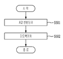
도 6은 일 실시예에 따른 절연형 멀티 입력 레귤레이팅 방법의 전체적인 흐름을 도시한다.6 illustrates an overall flow of an isolated multi-input regulating method according to one embodiment.
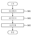
일 실시예에 있어서, 절연형 레귤레이팅 방법은 제 2 변환부(300)가 기설정된 범위의 전압을 출력하는 배터리로부터 전압을 입력받아 서로 다른 크기를 가지는 3개의 출력 전압으로 변환하여 3개의 출력단으로 출력하는 제 2 변환 단계(S501); 및 상기 제 2 변환부(300)는 3개의 출력단 중 적어도 2개의 출력단에서 출력되는 전압에 기초하여 피드백 전압을 입력받는 피드백 단계(S502);를 포함한다.In an embodiment, the insulated regulating method is a method in which the
절연형 멀티 입력 레귤레이팅 방법은 넓은 입력 범위에서 수행된다. 입력 범위는 예를 들어 2~40V이다. 절연형 멀티 입력 레귤레이팅 방법은 전기 자동차(Electric Vehicle; EV)에 구비된 절연형 멀티 입력 레귤레이터에서 수행되는 방법이다. 자세하게, 절연형 멀티 입력 레귤레이터는 전기자동차의 통신 컨트롤러(Communication Controller of Electric Vehicle; EVCC)에 구비되어, 통신 컨트롤러가 포함하는 캔(Controller Area Network, CAN) 전송기에 필요로 하는 전압을 공급한다. 이에 한정되는 것은 아니고, 통신 컨트롤러에 포함된 마이크로 컨트롤러 유닛(Micro controller unit; MCU)의 메인 전압 또는 마이크로 컨트롤러 유닛의 코어 전압을 공급한다.The isolated multi-input regulating method is performed over a wide input range. The input range is, for example, 2 to 40 V. An isolated multi-input regulating method is a method performed in an isolated multi-input regulator provided in an electric vehicle (EV). In detail, an insulated multi-input regulator is provided in a communication controller of an electric vehicle (EVCC) to supply a voltage required for a CAN (Controller Area Network) transmitter included in a communication controller. But is not limited to this, and supplies the main voltage of the micro controller unit (MCU) included in the communication controller or the core voltage of the microcontroller unit.
일 실시예에 있어서, 제 2 변환 단계(S501)는 제 2 변환부(300)가 기설정된 범위의 전압을 출력하는 배터리로부터 전압을 입력받아 서로 다른 크기를 가지는 3개의 출력 전압으로 변환하여 3개의 출력단으로 출력한다. 제 2 변환부(300)는 배터리(100)로부터 전압을 입력받는다. In the second conversion step S501, the
배터리(100)는 기설정된 범위의 전압을 출력한다 기설정된 범위의 전압은 예를 들어 2~40V이다. 이에 한정되는 것은 아니고 6~36V이다. 전술한 기설정된 범위의 전압은 전기 자동차가 포함하는 배터리(100)가 공급하는 전압이다.The
기설정된 범위의 전압을 입력받는 다는 것은 고정된 직류 전압을 입력 받되, 상기 고정된 직류 전압의 크기는 기설정된 범위내에 있음을 의미한다. 이에 한정되는 것은 아니고, 제 2 변환부(300)는 교류 전압을 공급 받을 수도 있다.Receiving a predetermined range of voltage means that a fixed DC voltage is input, and the magnitude of the fixed DC voltage is within a predetermined range. The present invention is not limited thereto, and the
제 2 변환부(300)는 입력단과 출력단이 절연되어 있는 것을 특징으로 한다.The
제 2 변환부(300)는 서로 다른 크기를 가지는 3개의 출력 전압을 3개의 출력단으로 출력한다. 3개의 출력단에서 출력되는 전압은 도 1 또는 도 2에 도시된 V1, V2, V3이다. 제 2 변환부(300)의 제 1 권선(L3)과 커플링된 권선은 제 2 권선(L4), 제 3 권선(L5), 제 4 권선(L6)이다.The
제 1 권선(L3)과 제 2 권선(L4)의 권선비에 따라 입력 전압과 다른 크기의 출력 전압 V1이 출력된다. 제 1 권선(L3)과 제 3 권선(L5)의 권선비에 따라 입력 전압과 다른 크기의 출력 전압 V2이 출력된다. 제 1 권선(L3)과 제 3 권선(L5)의 권선비에 따라 입력 전압과 다른 크기의 출력 전압 V3이 출력된다.An output voltage V1 having a magnitude different from the input voltage is output according to the turns ratio of the first winding L3 and the second winding L4. An output voltage V2 having a magnitude different from the input voltage is output according to the turns ratio of the first winding L3 and the third winding L5. An output voltage V3 having a magnitude different from that of the input voltage is output according to the turns ratio of the first winding L3 and the third winding L5.
제 2 변환부(300)의 어느 하나의 출력단은 통신 컨트롤러가 포함하는 캔(Controller Area Network, CAN) 전송기와 연결되어 5V를 공급할 수 있다.Any one of the output terminals of the
제 2 변환부(300)의 다른 하나의 출력단은 마이크로 컨트롤러 유닛과 연결되어 마이크로 컨트롤러 유닛 메인 전압인 3.3V를 공급할 수 있다.The other output terminal of the
제 2 변환부(300)의 또 다른 하나의 출력단은 마이크로 컨트롤러 유닛과 연결되어 마이크로 컨트롤러 유닛 코어 전압인 1.3V를 공급할 수 있다.Another output terminal of the
제 2 스위칭 소자의 온/오프에 따라 제 2 변환부(300)의 제 1 권선(L3)에 전류가 흐르거나 흐르지 않는다. 제 2 스위칭 소자는 도 2에 도시된 것 처럼 모스펫(MOSFET)일 수 있다. 이에 한정되는 것은 아니고, 양극성 접합 트랜지스터(Bipolar Junction Transistor, BJT) 등 다른 스위칭 소자일 수 있다.Current does not flow or flows in the first winding (L3) of the second converter (300) in accordance with the on / off state of the second switching element. The second switching device may be a MOSFET (MOSFET) as shown in Fig. But the present invention is not limited thereto, and may be other switching devices such as a bipolar junction transistor (BJT).
제 2 제어부는 상기 제 2 스위칭 소자의 온/오프를 제어한다.The second control unit controls on / off of the second switching device.
일 실시예에 있어서, 피드백 단계(S502)는 상기 제 2 변환부(300)는 3개의 출력단 중 적어도 2개의 출력단에서 출력되는 전압에 기초하여 피드백 전압을 입력받는다.In one embodiment, the feedback unit S502 receives the feedback voltage based on the voltage output from at least two of the three output units.
제 2 변환부(300)가 포함하는 제 2 제어부는 3개의 출력 단 중 적어도 2개의 출력단에서 출력되는 전압에 기초하여 피드백 전압을 입력 받는다.The second control unit included in the
제 2 제어부는 3개의 출력 단 중 적어도 2개의 출력단에서 출력되는 전압을 피드백 받아 제 2 스위칭부의 온/오프를 제어한다.The second control unit controls the on / off state of the second switching unit by receiving the voltage output from at least two of the three output stages.
일 실시예에 있어서, 상기 적어도 2개의 출력단 중 하나는 출력 전압이 가장 높은 출력단이고, 다른 하나는 부하에 연속적으로 전압을 공급하는 출력단인 것을 특징으로 한다.In one embodiment, one of the at least two output terminals is an output terminal with the highest output voltage, and the other is an output terminal that continuously supplies a voltage to the load.
출력 전압이 가장 높은 출력단은 통신 컨트롤러가 포함하는 캔 전송기와 연결된 출력단이다.The output terminal with the highest output voltage is the output terminal connected to the CAN transmitter included in the communication controller.
출력 전압이 가장 높은 출력단이 출력하는 전압을 제 2 변환부(300)가 피드백 받음에 따라, 더 정밀하게 제 2 스위칭 소자를 제어할 수 있다. 출력 전압의 크기가 크면 출력 전압의 최대값과 최소값의 차이도 커지게 되어 제 2 변환부(300)는 세밀한 피드백을 받을 수 있다.The
연속적으로 전압을 공급하는 출력단은 마이크로 컨트롤러 유닛과 연결되어 마이크로 컨트롤러 유닛 코어 전압을 공급하는 출력단이다.An output terminal for supplying a continuous voltage is an output terminal connected to the microcontroller unit to supply a microcontroller unit core voltage.
연속적으로 전압을 공급하는 출력단이 출력하는 전압을 제 2 변환부(300)가 피드백 받음에 따라, 시간적인 공백 없이 연속적으로 현재 출력 전압에 기초하여 제 2 스위칭 소자를 제어할 수 있다.The second switching unit can be continuously controlled based on the current output voltage without temporal blanking as the second converting
도 7은 다른 실시예에 따른 절연형 멀티 입력 레귤레이팅 방법의 전체적인 흐름을 도시한다.FIG. 7 shows an overall flow of an isolated multi-input regulating method according to another embodiment.
일 실시예에 있어서, 절연형 멀티 입력 레귤레이팅 방법은 제 1 변환부가 기설정된 범위의 전압을 입력받아 제 1 전압으로 변환하여 제 2 변환부로 출력하는 제 1 변환 단계(S601);를 더 포함한다.In one embodiment, the method of isolating multi-input regulating further includes a first converting step (S601) in which the first converting unit receives a voltage of a predetermined range, converts the voltage into a first voltage, and outputs the first voltage to the second converting unit .
제 1 변환부는 기설정된 범위의 전압을 입력 받아 12V의 전압으로 변환하여 출력한다. 이에 한정되는 것은 아니고, 제 1 변환부는 2~40V 범위에 있는 직류 전압을 출력할 수 있다.The first conversion unit receives a voltage of a predetermined range, converts the voltage into a voltage of 12V, and outputs the converted voltage. However, the present invention is not limited to this, and the first conversion unit can output a DC voltage in the range of 2 to 40V.
일 실시예에 있어서, 상기 피드백 단계(S603)는 제 1 변환부 및 제 2 변환부는 제 2 변환부의 출력단에 연결된 포토 커플러가 출력하는 피드백 전압을 입력받는 것을 특징으로 한다.In one embodiment, the feedback step S603 is characterized in that the first conversion unit and the second conversion unit receive the feedback voltage output from the photocoupler connected to the output terminal of the second conversion unit.
제 1 변환부 및 제 2 변환부는 제 2 변환부의 출력단에 연결된 포토 커플러가 출력하는 피드백 전압을 통해 단일 피드백을 받는다.The first conversion unit and the second conversion unit receive a single feedback through the feedback voltage outputted from the photocoupler connected to the output terminal of the second conversion unit.
제 2 변환부의 포토 커플러의 발광 소자와 연결된 가변 정밀 제너 션트 레귤레이터(Adjustable Precision Zener Shunt Regulator)에 기준 이상의 전압이 인가되면 포토 커플러가 포함하는 발광 소자에 전류가 흐름에 따라 발광 소자는 발광한다. 발광 소자가 발광함에 따라 수광 소자는 온되어 제 1 변환부 및 제 2 변환부로 피드백 전압이 공급된다.When a voltage equal to or higher than a reference voltage is applied to the variable precision zener shunt regulator connected to the light emitting element of the photocoupler of the second conversion unit, the light emitting element emits light as current flows through the light emitting element included in the photocoupler. As the light emitting device emits light, the light receiving element is turned on and a feedback voltage is supplied to the first and second conversion units.
일 실시예에 있어서, 상기 피드백 단계(S603)는 제 1 변환부는 제 1 변환부의 출력 전압을 피드백 전압으로 입력 받고, 제 2 변환부는 제 2 변환부의 출력단에 연결된 포토 커플러가 출력하는 피드백 전압을 입력받는 것을 특징으로 한다.In an exemplary embodiment, the feedback step S603 may include receiving the feedback voltage output from the first conversion unit as a feedback voltage and the feedback voltage output from the photo-coupler connected to the output unit of the second conversion unit, .
제 1 변환부 및 제 2 변환부는 각각 상이한 피드백 전압을 입력 받는다.Each of the first and second converters receives a different feedback voltage.
제 1 변환부는 제 1 변환부의 출력단에 직렬 연결된 2개의 저항 중 접지에 연결된 저항의 크기에 비례하여 피드백 전압을 입력받는다.The first converter receives the feedback voltage proportional to the magnitude of the resistor connected to the ground among the two resistors connected in series to the output terminal of the first converter.
제 2 변환부의 포토 커플러의 발광 소자와 연결된 가변 정밀 제너 션트 레귤레이터(Adjustable Precision Zener Shunt Regulator)에 기준 이상의 전압이 인가되면 포토 커플러가 포함하는 발광 소자에 전류가 흐름에 따라 발광 소자는 발광한다. 발광 소자가 발광함에 따라 수광 소자는 온되어 제 2 변환부로 피드백 전압이 공급된다.When a voltage equal to or higher than a reference voltage is applied to the variable precision zener shunt regulator connected to the light emitting element of the photocoupler of the second conversion unit, the light emitting element emits light as current flows through the light emitting element included in the photocoupler. As the light emitting device emits light, the light receiving element is turned on and a feedback voltage is supplied to the second conversion unit.
이와 같이, 본 발명이 속하는 기술분야에서 통상의 지식을 가진 자는 본 발명이 그 기술적 사상이나 필수적인 특징을 변경하지 않고서 다른 구체적인 실시 형태로 실시될 수 있다는 것을 인지할 수 있을 것이다. 따라서 이상에서 기술한 실시 예들은 예시적인 것일 뿐이며, 그 범위를 제한해놓은 한정적인 것이 아닌 것으로 이해해야만 한다. 또한, 도면에 도시된 순서도들은 본 발명을 실시함에 있어서 가장 바람직한 결과를 달성하기 위해 예시적으로 도시된 순차적인 순서에 불과하며, 다른 추가적인 단계들이 제공되거나, 일부 단계가 삭제될 수 있음은 물론이다.Thus, those skilled in the art will appreciate that the present invention may be embodied in other specific forms without departing from the spirit or essential characteristics thereof. It is therefore to be understood that the above-described embodiments are illustrative only and not restrictive of the scope of the invention. It is also to be understood that the flow charts shown in the figures are merely the sequential steps illustrated in order to achieve the most desirable results in practicing the present invention and that other additional steps may be provided or some steps may be deleted .
이와 같이, 본 명세서는 그 제시된 구체적인 용어에 의해 본 발명을 제한하려는 의도가 아니다. 따라서, 이상에서 기술한 실시 예를 참조하여 본 발명을 상세하게 설명하였지만, 본 발명이 속하는 기술분야에서 통상의 지식을 가진 자라면 본 발명의 범위를 벗어나지 않으면서도 본 실시 예들에 대한 개조, 변경 및 변형을 가할 수 있다.As such, the specification is not intended to limit the invention to the precise form disclosed. While the present invention has been particularly shown and described with reference to exemplary embodiments thereof, it is evident that many alternatives, modifications, and variations will be apparent to those skilled in the art without departing from the spirit and scope of the present invention as defined by the appended claims. It is possible to apply a deformation.
본 발명의 범위는 상기 상세한 설명보다는 후술하는 특허청구범위에 의하여 나타내어지며, 특허청구범위의 의미 및 범위 그리고 그 등가개념으로부터 도출되는 모든 변경 또는 변형된 형태가 본 발명의 권리범위에 포함되는 것으로 해석되어야 한다.The scope of the present invention is defined by the appended claims rather than the foregoing description, and all changes or modifications derived from the meaning and scope of the claims and equivalents thereof are deemed to be included in the scope of the present invention. .
100: 배터리
200: 제 1 변환부
300: 제 2 변환부
320: 포토 커플러
321: 수광 소자
322: 발광 소자
330: 가변 정밀 제너 션트 레귤레이터
L1: 제 1 인덕터
M1: 제 1 스위칭 소자
C1: 제 1 커패시터
L2: 제 2 인덕터
D1: 제 1 다이오드
C2: 제 2 커패시터
L3: 제 1 권선
L4: 제 2 권선
L5: 제 3 권선
L6: 제 4 권선
D2: 제 2 다이오드
D3: 제 3 다이오드
D4: 제 4 다이오드
C3: 제 3 커패시터
C4: 제 4 커패시터
C5: 제 5 커패시터100: Battery
200: first conversion section
300: second conversion section
320: Photo coupler
321: Light receiving element
322: Light emitting element
330: Variable Precision Zenerant Regulator
L1: first inductor
M1: first switching element
C1: first capacitor
L2: second inductor
D1: first diode
C2: second capacitor
L3: 1st winding
L4: Secondary winding
L5: Third winding
L6: Fourth winding
D2: second diode
D3: Third diode
D4: fourth diode
C3: third capacitor
C4: fourth capacitor
C5: fifth capacitor
Claims (9)
상기 제 2 변환부는 3개의 출력단 중 적어도 2개의 출력단에서 출력되는 전압에 기초하여 피드백 전압을 입력받고,
상기 적어도 2개의 출력단 중 하나는 출력 전압이 가장 높은 출력단이고, 다른 하나는 부하에 연속적으로 전압을 공급하는 출력단인
절연형 멀티 입력 레귤레이터
And a second conversion unit that receives a voltage from a battery that receives a voltage and outputs a predetermined range of voltages having different sizes, converts the voltage into three output voltages having different sizes, and outputs the output voltage to three output terminals,
Wherein the second converter receives a feedback voltage based on a voltage output from at least two of the three output terminals,
One of the at least two output stages is an output stage having the highest output voltage, and the other is an output stage
Isolated multi-input regulator
상기 적어도 2개의 출력단과 기준단자가 연결되는 가변 정밀 제너 션트 레귤레이터; 및
상기 가변 정밀 제너 션트 레귤레이터에 기준 전압 이상의 전압이 인가되면 상기 제 2 변환부로 피드백 전압을 공급하는 포토 커플러;를 포함하는
절연형 멀티 입력 레귤레이터
The method according to claim 1,
A variable precision zener regulator in which at least two output terminals are connected to a reference terminal; And
And an optocoupler that supplies a feedback voltage to the second conversion unit when a voltage equal to or higher than a reference voltage is applied to the variable precision zener regulator
Isolated multi-input regulator
기설정된 범위의 전압을 입력받아 제 1 전압으로 변환하여 상기 제 2 변환부로 출력하는 제 1 변환부;를 더 포함하는,
절연형 멀티 입력 레귤레이터
The method according to claim 1,
And a first converter for converting a voltage of a predetermined range into a first voltage and outputting the voltage to the second converter,
Isolated multi-input regulator
상기 제 1 변환부 및 상기 제 2 변환부는 상기 제 2 변환부의 출력단에 연결된 포토 커플러가 출력하는 피드백 전압을 입력받거나,
상기 제 1 변환부는 상기 제 1 변환부의 출력 전압을 피드백 전압으로 입력 받고,
상기 제 2 변환부는 상기 제 2 변환부의 출력단에 연결된 포토 커플러가 출력하는 피드백 전압을 입력받는 것을 특징으로 하는
절연형 멀티 입력 레귤레이터
The method of claim 3,
The first conversion unit and the second conversion unit may receive a feedback voltage output from a photocoupler connected to an output terminal of the second conversion unit,
The first conversion unit receives the output voltage of the first conversion unit as a feedback voltage,
And the second converter receives the feedback voltage output from the photocoupler connected to the output terminal of the second converter
Isolated multi-input regulator
제 1 인덕터;
상기 제 1 인덕터와 일단이 연결되는 제 1 스위칭 소자;
상기 제 1 스위칭 소자를 제어하는 제 1 제어부;
상기 제 1 스위칭 소자의 일단과 연결되는 제 1 커패시터;
상기 제 1 커패시터와 일단이 연결되는 제 2 인덕터;
상기 제 2 인덕터와 에노드가 연결되는 제 1 다이오드; 및
상기 제 1 다이오드와 일단이 연결되는 제 2 커패시터;를 포함하는,
절연형 멀티 입력 레귤레이터.
The image processing apparatus according to claim 3,
A first inductor;
A first switching device having a first end connected to the first inductor;
A first control unit for controlling the first switching device;
A first capacitor connected to one end of the first switching device;
A second inductor whose one end is connected to the first capacitor;
A first diode having a node connected to the second inductor; And
And a second capacitor having one end connected to the first diode,
Isolated multi-input regulator.
제 1 권선;
상기 제 1 권선과 일단이 연결된 제 2 스위칭 소자;
상기 제 2 스위칭 소자를 제어하는 제 2 제어부;
상기 제 1 권선과 커플링 된 제 2 권선;
상기 제 2 권선과 에노드가 연결되는 제 2 다이오드;
상기 제 2 다이오드와 일단이 연결되는 제 3 커패시터;
상기 제 1 권선과 커플링 된 제 3 권선;
상기 제 3 권선과 에노드가 연결되는 제 3 다이오드;
상기 제 3 다이오드와 일단이 연결되는 제 4 커패시터;
상기 제 1 권선과 커플링 된 제 4 권선;
상기 제 4 권선과 에노드가 연결되는 제 4 다이오드;
상기 제 4 다이오드와 일단이 연결되는 제 5 커패시터;
를 포함하는,
절연형 멀티 입력 레귤레이터.
The apparatus of claim 1, wherein the second conversion unit
A first winding;
A second switching element connected to the first winding at one end;
A second controller for controlling the second switching element;
A second winding coupled to the first winding;
A second diode having a node connected to the second winding;
A third capacitor whose one end is connected to the second diode;
A third winding coupled to the first winding;
A third diode having a node connected to the third winding;
A fourth capacitor having one end connected to the third diode;
A fourth winding coupled to the first winding;
A fourth diode having a node connected to the fourth winding;
A fifth capacitor whose one end is connected to the fourth diode;
/ RTI >
Isolated multi-input regulator.
상기 제 2 변환부는 3개의 출력단 중 적어도 2개의 출력단에서 출력되는 전압에 기초하여 피드백 전압을 입력받는 피드백 단계;를 포함하되,
상기 적어도 2개의 출력단 중 하나는 출력 전압이 가장 높은 출력단이고, 다른 하나는 부하에 연속적으로 전압을 공급하는 출력단인
절연형 멀티 입력 레귤레이팅 방법.
A second conversion step of receiving a voltage from a battery outputting a voltage of a predetermined range and converting the voltage into three output voltages having different sizes and outputting the output voltages to three output terminals; And
And the second conversion unit includes a feedback step of receiving a feedback voltage based on a voltage output from at least two of the three output stages,
One of the at least two output stages is an output stage having the highest output voltage, and the other is an output stage
Isolated multi-input regulating method.
제 1 변환부가 기설정된 범위의 전압을 입력받아 제 1 전압으로 변환하여 상기 제 2 변환부로 출력하는 OI제 1 변환 단계;를 더 포함하는
절연형 멀티 입력 레귤레이팅 방법.
8. The method of claim 7,
And an OI first converting step of converting a voltage of a predetermined range into a first voltage and outputting the voltage to the second converting unit,
Isolated multi-input regulating method.
상기 피드백 단계는
상기 제 1 변환부 및 상기 2 변환부는 상기 제 2 변환부의 출력단에 연결된 포토 커플러가 출력하는 피드백 전압을 입력받거나,
상기 제 1 변환부는 상기 제 1 변환부의 출력 전압을 피드백 전압으로 입력 받고,
상기 제 2 변환부는 상기 제 2 변환부의 출력단에 연결된 포토 커플러가 출력하는 피드백 전압을 입력받는 것을 특징으로 하는
절연형 멀티 입력 레귤레이팅 방법.
9. The method of claim 8,
The feedback step
The first converter and the second converter may receive a feedback voltage output from the photocoupler connected to the output of the second converter,
The first conversion unit receives the output voltage of the first conversion unit as a feedback voltage,
And the second converter receives the feedback voltage output from the photocoupler connected to the output terminal of the second converter
Isolated multi-input regulating method.
Priority Applications (1)
| Application Number | Priority Date | Filing Date | Title |
|---|---|---|---|
| KR1020170025310A KR102615836B1 (en) | 2017-02-27 | 2017-02-27 | Isolated multi-input regulator and Isolated Multi-Input Regulating Method |
Applications Claiming Priority (1)
| Application Number | Priority Date | Filing Date | Title |
|---|---|---|---|
| KR1020170025310A KR102615836B1 (en) | 2017-02-27 | 2017-02-27 | Isolated multi-input regulator and Isolated Multi-Input Regulating Method |
Publications (2)
| Publication Number | Publication Date |
|---|---|
| KR20180098774A true KR20180098774A (en) | 2018-09-05 |
| KR102615836B1 KR102615836B1 (en) | 2023-12-19 |
Family
ID=63594254
Family Applications (1)
| Application Number | Title | Priority Date | Filing Date |
|---|---|---|---|
| KR1020170025310A Active KR102615836B1 (en) | 2017-02-27 | 2017-02-27 | Isolated multi-input regulator and Isolated Multi-Input Regulating Method |
Country Status (1)
| Country | Link |
|---|---|
| KR (1) | KR102615836B1 (en) |
Cited By (3)
| Publication number | Priority date | Publication date | Assignee | Title |
|---|---|---|---|---|
| KR20200032569A (en) * | 2018-09-18 | 2020-03-26 | 엘지이노텍 주식회사 | Power regulator including feedback circuit |
| CN112636574A (en) * | 2020-12-30 | 2021-04-09 | 华清瑞达(天津)科技有限公司 | Power output protection circuit |
| DE102024126866A1 (en) * | 2024-09-19 | 2026-03-19 | sonnen GmbH | ANALOG FRONTEND CIRCUIT FOR A BATTERY SYSTEM |
Citations (4)
| Publication number | Priority date | Publication date | Assignee | Title |
|---|---|---|---|---|
| KR20060106081A (en) * | 2005-04-06 | 2006-10-12 | 주식회사 엘지화학 | Multi DC output power system |
| KR20080024321A (en) * | 2006-09-13 | 2008-03-18 | 삼성에스디아이 주식회사 | Power supply, plasma display including power supply and standby voltage generation method thereof |
| KR20080110376A (en) * | 2007-06-15 | 2008-12-18 | 엘에스전선 주식회사 | Multi-output adapter |
| KR20100027528A (en) * | 2008-09-02 | 2010-03-11 | 페어차일드코리아반도체 주식회사 | Switch mode power supply and the driving method thereof |
-
2017
- 2017-02-27 KR KR1020170025310A patent/KR102615836B1/en active Active
Patent Citations (4)
| Publication number | Priority date | Publication date | Assignee | Title |
|---|---|---|---|---|
| KR20060106081A (en) * | 2005-04-06 | 2006-10-12 | 주식회사 엘지화학 | Multi DC output power system |
| KR20080024321A (en) * | 2006-09-13 | 2008-03-18 | 삼성에스디아이 주식회사 | Power supply, plasma display including power supply and standby voltage generation method thereof |
| KR20080110376A (en) * | 2007-06-15 | 2008-12-18 | 엘에스전선 주식회사 | Multi-output adapter |
| KR20100027528A (en) * | 2008-09-02 | 2010-03-11 | 페어차일드코리아반도체 주식회사 | Switch mode power supply and the driving method thereof |
Cited By (3)
| Publication number | Priority date | Publication date | Assignee | Title |
|---|---|---|---|---|
| KR20200032569A (en) * | 2018-09-18 | 2020-03-26 | 엘지이노텍 주식회사 | Power regulator including feedback circuit |
| CN112636574A (en) * | 2020-12-30 | 2021-04-09 | 华清瑞达(天津)科技有限公司 | Power output protection circuit |
| DE102024126866A1 (en) * | 2024-09-19 | 2026-03-19 | sonnen GmbH | ANALOG FRONTEND CIRCUIT FOR A BATTERY SYSTEM |
Also Published As
| Publication number | Publication date |
|---|---|
| KR102615836B1 (en) | 2023-12-19 |
Similar Documents
| Publication | Publication Date | Title |
|---|---|---|
| US11230201B2 (en) | System of charging battery of vehicle and method for controlling the same | |
| KR20170126053A (en) | Bidirectional powering on board charger, vehicle power providing system comprising the same, and control method therefor | |
| US9776518B2 (en) | System with battery charging device and vehicle electrical system power supply stage | |
| KR20200122033A (en) | united converter apparatus | |
| KR20210156107A (en) | Apparatus and method for charging battery of vehicle | |
| CN104377791A (en) | Converter apparatus and method of electric vehicle | |
| US9193275B2 (en) | In-vehicle charger | |
| KR20150075591A (en) | Apparatus and method for providing multi-voltage output of low voltage dc-dc converter of environmentally friendly vehicle | |
| KR20160050953A (en) | Apparatus for converting power of electric vehicle | |
| CN110999053A (en) | Adjustable power supply device for supplying power to power switch control device | |
| US5717579A (en) | Power supply unit, more specifically battery charger for electric vehicles and the like | |
| KR102615836B1 (en) | Isolated multi-input regulator and Isolated Multi-Input Regulating Method | |
| KR102338378B1 (en) | Battery charging system of vehicle | |
| JP6642119B2 (en) | Charger | |
| KR20130117210A (en) | Vehicle battery charging system | |
| JP5255094B2 (en) | DC-DC converter and DC-DC converter system | |
| CN114649949A (en) | High-capacity bidirectional isolation type direct current-direct current converter and control method thereof | |
| CN111231669B (en) | On-board chargers, power supply systems for electric vehicles, electric vehicles | |
| KR102227190B1 (en) | On board Charger for electric vehicle | |
| KR20180123834A (en) | Voltage sensing apparatus | |
| WO2024106382A1 (en) | Power supply device | |
| CN107005162A (en) | Dc voltage changer system, DC-voltage supply system and the printed circuit board (PCB) for dc voltage changer system | |
| JP4871647B2 (en) | DC-DC converter and DC-DC converter system | |
| CN209526519U (en) | Support the power supply device of Power over Ethernet | |
| KR101387239B1 (en) | Power converting apparatus |
Legal Events
| Date | Code | Title | Description |
|---|---|---|---|
| PA0109 | Patent application |
Patent event code: PA01091R01D Comment text: Patent Application Patent event date: 20170227 |
|
| PG1501 | Laying open of application | ||
| A201 | Request for examination | ||
| PA0201 | Request for examination |
Patent event code: PA02012R01D Patent event date: 20220128 Comment text: Request for Examination of Application Patent event code: PA02011R01I Patent event date: 20170227 Comment text: Patent Application |
|
| E902 | Notification of reason for refusal | ||
| PE0902 | Notice of grounds for rejection |
Comment text: Notification of reason for refusal Patent event date: 20230609 Patent event code: PE09021S01D |
|
| E701 | Decision to grant or registration of patent right | ||
| PE0701 | Decision of registration |
Patent event code: PE07011S01D Comment text: Decision to Grant Registration Patent event date: 20231011 |
|
| GRNT | Written decision to grant | ||
| PR0701 | Registration of establishment |
Comment text: Registration of Establishment Patent event date: 20231215 Patent event code: PR07011E01D |
|
| PR1002 | Payment of registration fee |
Payment date: 20231215 End annual number: 3 Start annual number: 1 |
|
| PG1601 | Publication of registration |