KR20180098684A - Apparatus for automated positioning of eddy current test probe - Google Patents
Apparatus for automated positioning of eddy current test probe Download PDFInfo
- Publication number
- KR20180098684A KR20180098684A KR1020187024283A KR20187024283A KR20180098684A KR 20180098684 A KR20180098684 A KR 20180098684A KR 1020187024283 A KR1020187024283 A KR 1020187024283A KR 20187024283 A KR20187024283 A KR 20187024283A KR 20180098684 A KR20180098684 A KR 20180098684A
- Authority
- KR
- South Korea
- Prior art keywords
- tube
- gripper
- grippers
- robot
- housing
- Prior art date
- Legal status (The legal status is an assumption and is not a legal conclusion. Google has not performed a legal analysis and makes no representation as to the accuracy of the status listed.)
- Granted
Links
Images

Classifications
-
- B—PERFORMING OPERATIONS; TRANSPORTING
- B66—HOISTING; LIFTING; HAULING
- B66C—CRANES; LOAD-ENGAGING ELEMENTS OR DEVICES FOR CRANES, CAPSTANS, WINCHES, OR TACKLES
- B66C1/00—Load-engaging elements or devices attached to lifting or lowering gear of cranes or adapted for connection therewith for transmitting lifting forces to articles or groups of articles
- B66C1/10—Load-engaging elements or devices attached to lifting or lowering gear of cranes or adapted for connection therewith for transmitting lifting forces to articles or groups of articles by mechanical means
- B66C1/42—Gripping members engaging only the external or internal surfaces of the articles
- B66C1/44—Gripping members engaging only the external or internal surfaces of the articles and applying frictional forces
- B66C1/54—Internally-expanding grippers for handling hollow articles
-
- B—PERFORMING OPERATIONS; TRANSPORTING
- B25—HAND TOOLS; PORTABLE POWER-DRIVEN TOOLS; MANIPULATORS
- B25J—MANIPULATORS; CHAMBERS PROVIDED WITH MANIPULATION DEVICES
- B25J15/00—Gripping heads and other end effectors
-
- B—PERFORMING OPERATIONS; TRANSPORTING
- B66—HOISTING; LIFTING; HAULING
- B66C—CRANES; LOAD-ENGAGING ELEMENTS OR DEVICES FOR CRANES, CAPSTANS, WINCHES, OR TACKLES
- B66C1/00—Load-engaging elements or devices attached to lifting or lowering gear of cranes or adapted for connection therewith for transmitting lifting forces to articles or groups of articles
- B66C1/10—Load-engaging elements or devices attached to lifting or lowering gear of cranes or adapted for connection therewith for transmitting lifting forces to articles or groups of articles by mechanical means
- B66C1/42—Gripping members engaging only the external or internal surfaces of the articles
- B66C1/44—Gripping members engaging only the external or internal surfaces of the articles and applying frictional forces
- B66C1/54—Internally-expanding grippers for handling hollow articles
- B66C1/56—Internally-expanding grippers for handling hollow articles for handling tubes
-
- F—MECHANICAL ENGINEERING; LIGHTING; HEATING; WEAPONS; BLASTING
- F22—STEAM GENERATION
- F22B—METHODS OF STEAM GENERATION; STEAM BOILERS
- F22B37/00—Component parts or details of steam boilers
- F22B37/002—Component parts or details of steam boilers specially adapted for nuclear steam generators, e.g. maintenance, repairing or inspecting equipment not otherwise provided for
- F22B37/003—Maintenance, repairing or inspecting equipment positioned in or via the headers
- F22B37/005—Positioning apparatus specially adapted therefor
-
- F—MECHANICAL ENGINEERING; LIGHTING; HEATING; WEAPONS; BLASTING
- F22—STEAM GENERATION
- F22B—METHODS OF STEAM GENERATION; STEAM BOILERS
- F22B37/00—Component parts or details of steam boilers
- F22B37/002—Component parts or details of steam boilers specially adapted for nuclear steam generators, e.g. maintenance, repairing or inspecting equipment not otherwise provided for
- F22B37/006—Walking equipment, e.g. walking platforms suspended at the tube sheet
-
- G—PHYSICS
- G01—MEASURING; TESTING
- G01D—MEASURING NOT SPECIALLY ADAPTED FOR A SPECIFIC VARIABLE; ARRANGEMENTS FOR MEASURING TWO OR MORE VARIABLES NOT COVERED IN A SINGLE OTHER SUBCLASS; TARIFF METERING APPARATUS; MEASURING OR TESTING NOT OTHERWISE PROVIDED FOR
- G01D11/00—Component parts of measuring arrangements not specially adapted for a specific variable
- G01D11/30—Supports specially adapted for an instrument; Supports specially adapted for a set of instruments
-
- G—PHYSICS
- G01—MEASURING; TESTING
- G01M—TESTING STATIC OR DYNAMIC BALANCE OF MACHINES OR STRUCTURES; TESTING OF STRUCTURES OR APPARATUS, NOT OTHERWISE PROVIDED FOR
- G01M5/00—Investigating the elasticity of structures, e.g. deflection of bridges or air-craft wings
- G01M5/0025—Investigating the elasticity of structures, e.g. deflection of bridges or air-craft wings of elongated objects, e.g. pipes, masts, towers or railways
-
- G—PHYSICS
- G01—MEASURING; TESTING
- G01M—TESTING STATIC OR DYNAMIC BALANCE OF MACHINES OR STRUCTURES; TESTING OF STRUCTURES OR APPARATUS, NOT OTHERWISE PROVIDED FOR
- G01M5/00—Investigating the elasticity of structures, e.g. deflection of bridges or air-craft wings
- G01M5/0033—Investigating the elasticity of structures, e.g. deflection of bridges or air-craft wings by determining damage, crack or wear
-
- G—PHYSICS
- G01—MEASURING; TESTING
- G01M—TESTING STATIC OR DYNAMIC BALANCE OF MACHINES OR STRUCTURES; TESTING OF STRUCTURES OR APPARATUS, NOT OTHERWISE PROVIDED FOR
- G01M5/00—Investigating the elasticity of structures, e.g. deflection of bridges or air-craft wings
- G01M5/0091—Investigating the elasticity of structures, e.g. deflection of bridges or air-craft wings by using electromagnetic excitation or detection
-
- G—PHYSICS
- G01—MEASURING; TESTING
- G01N—INVESTIGATING OR ANALYSING MATERIALS BY DETERMINING THEIR CHEMICAL OR PHYSICAL PROPERTIES
- G01N27/00—Investigating or analysing materials by the use of electric, electrochemical, or magnetic means
- G01N27/72—Investigating or analysing materials by the use of electric, electrochemical, or magnetic means by investigating magnetic variables
- G01N27/82—Investigating or analysing materials by the use of electric, electrochemical, or magnetic means by investigating magnetic variables for investigating the presence of flaws
- G01N27/90—Investigating or analysing materials by the use of electric, electrochemical, or magnetic means by investigating magnetic variables for investigating the presence of flaws using eddy currents
- G01N27/9013—Arrangements for scanning
- G01N27/902—Arrangements for scanning by moving the sensors
-
- Y—GENERAL TAGGING OF NEW TECHNOLOGICAL DEVELOPMENTS; GENERAL TAGGING OF CROSS-SECTIONAL TECHNOLOGIES SPANNING OVER SEVERAL SECTIONS OF THE IPC; TECHNICAL SUBJECTS COVERED BY FORMER USPC CROSS-REFERENCE ART COLLECTIONS [XRACs] AND DIGESTS
- Y10—TECHNICAL SUBJECTS COVERED BY FORMER USPC
- Y10T—TECHNICAL SUBJECTS COVERED BY FORMER US CLASSIFICATION
- Y10T29/00—Metal working
- Y10T29/51—Plural diverse manufacturing apparatus including means for metal shaping or assembling
- Y10T29/5199—Work on tubes
Landscapes
- Engineering & Computer Science (AREA)
- Physics & Mathematics (AREA)
- Mechanical Engineering (AREA)
- General Physics & Mathematics (AREA)
- Aviation & Aerospace Engineering (AREA)
- Chemical & Material Sciences (AREA)
- General Engineering & Computer Science (AREA)
- Thermal Sciences (AREA)
- High Energy & Nuclear Physics (AREA)
- Life Sciences & Earth Sciences (AREA)
- Health & Medical Sciences (AREA)
- Pathology (AREA)
- Chemical Kinetics & Catalysis (AREA)
- General Health & Medical Sciences (AREA)
- Biochemistry (AREA)
- Analytical Chemistry (AREA)
- Immunology (AREA)
- Electrochemistry (AREA)
- Electromagnetism (AREA)
- Robotics (AREA)
- Manipulator (AREA)
- Investigating Or Analyzing Materials By The Use Of Magnetic Means (AREA)
- Monitoring And Testing Of Nuclear Reactors (AREA)
Abstract
튜브 시트의 자동 검사 및 수리를 위한 장치로, 상기 장치는 적어도 하나의 튜브 그리퍼를 포함하는 회전 그리퍼 포드를 포함하는 슬라이딩 몸체 부분, 적어도 하나의 튜브 그리퍼를 포함하는 하우징 부분, 및 도구 헤드 커플링을 포함한다. 상기 도구 헤드 커플링은 에디 전류 테스트 프로브 및 적어도 한 종류의 튜브 수리 도구에 교환가능하게 부착되어 있다. 신규한 자동잠김 튜브 그리퍼들 또한 개시되고 있다. 직렬 버스는 상기 장치 안의 전자 모듈들을 연결하고 상기 장치를 외부 컨트롤러에 연결한다. An apparatus for automatic inspection and repair of a tubesheet, the apparatus comprising: a sliding body portion including a rotating gripper pod including at least one tube gripper; a housing portion including at least one tube gripper; and a tool head coupling . The tool head coupling is replaceably attached to an eddy current test probe and at least one type of tube repair tool. New automatic locking tube grippers are also disclosed. A serial bus connects the electronic modules within the device and connects the device to an external controller.
Description
본 발명은 자동 검사 및 수리 시스템에 관한 것으로서, 보다 상세하게는 증기 생성기 튜브들의 어레이 안에 에디 전류 테스트 프로브(an eddy current test probe)를 위치시키는 로봇 장치에 관한 것이다. The present invention relates to an automatic inspection and repair system, and more particularly to a robotic device for positioning an eddy current test probe in an array of steam generator tubes.
본 출원서는 2010년 1월 14일에 출원되어, 진행중인 미국 출원 제 12/687,261호의 분할 출원이며, 2009년 1월 19일에 출원된 미국 가출원 제 61/145,629호에 대하여 우선권을 주장하고, 이들 각각은 그 전체로서 여기에 참조에 의해 반영된다. This application is a divisional application of US Provisional Application No. 12 / 687,261, filed on January 14, 2010, and claims priority to U.S. Provisional Application No. 61 / 145,629, filed January 19, 2009, Quot; is hereby incorporated by reference in its entirety.
증기 생성기 튜브 시트(steam generator tube sheets)의 정기적 검사 및 테스트는 증기 생성기 공장의 가동에 있어 중요한 일이다. 튜브 시트는 적어도 하나의 끝단에서는 접근할 수 있는 평행한 튜브들의 어레이이고, 상기 튜브 끝단은 하나의 평면에 배치되어 있다. 각 튜브의 테스트는 정교하고 시간이 많이 든다. 과거에 이것은 튜브 안에 테스트 프로브들을 수동으로 넣는 것에 의해 수행되었다. Periodic inspection and testing of steam generator tube sheets is an important task in the operation of the steam generator plant. The tube sheet is an array of parallel tubes accessible at least at one end, the tube ends being arranged in one plane. Testing of each tube is elaborate and time consuming. In the past, this was done by manually inserting test probes into the tube.
여기서 설명할 것은 증기 생성기를 위한 튜브 시트 안에 테스트 및 수리 장치를 위치시키는 개선된 자동 장치이다.Described herein is an improved automated apparatus for placing test and repair equipment within a tube sheet for a steam generator.
이러한 자동 장치의 바람직한 특성들은, 한 사람에 의한 빠른 설치(installation), 취급을 위한 통합된 그랩 특성(integrated grab features for handling), 보호 범퍼, 튜브 시트와 증기 생성기의 독립적 특성, 단순한 배선 시스템 및 단일 지점 배선 연결, 단순화된 조정(calibration), 오염방지의 용이함, 데이터 획득 시스템과의 완벽한 통합, 빠르고 정확한 수행능력 및 수리 도구의 지지를 포함한다. Desirable characteristics of such an automatic device include rapid installation by one person, integrated grab features for handling, independent characteristics of the protective bumper, tube sheet and steam generator, simple wiring system and single Point wiring, simplified calibration, ease of contamination prevention, complete integration with data acquisition systems, fast and accurate performance and support for repair tools.
로봇 도구 포지셔너(robotic tool positioner)는 증기 생성기에서와 같이, 튜브 어레이 안에 도구 및 테스트 장비를 위치시키기에 특히 적합하다. 도구 포지셔너는 여기 설명된 여러 가지 신규한 특성들을 가진다. A robotic tool positioner is particularly suited for positioning tools and test equipment in a tube array, such as in a steam generator. The tool positioner has a number of novel features described herein.
일 실시예에 있어서, 상기 도구 포지셔너는 개방 튜브들의 튜브 시트의 면을 가로질러 움직이도록 되어 있다. 상기 포지셔너는, 적어도 하나의 튜브 그리퍼를 포함하는 회전 그리퍼 포드(a rotating gripper pod)를 갖는 슬라이딩 몸체 부분(a sliding body portion), 각각 적어도 하나의 튜브 그리퍼를 가지는 좌측 및 우측 외부 하우징 부분 및 에디 전류 테스트 프로브, 수리 및 유지 도구들을 포함하는 다양한 부착물들을 지지하는 도구 헤드 커플링 포함한다. 슬라이딩 몸체 부분은 하우징 부분에 대하여 상기 튜브 시트를 가로질러 측면으로 움직인다. 회전 그리퍼 포드는 포지셔너가 튜브 시트의 평면에 수직한 축으로 회전하도록 허용한다.In one embodiment, the tool positioner is adapted to move across the face of the tube sheet of open tubes. The positioner includes a sliding body portion having a rotating gripper pod including at least one tube gripper, a left and right outer housing portion each having at least one tube gripper, A test probe, a tool head coupling that supports various attachments including repair and maintenance tools. The sliding body portion moves laterally across the tube sheet relative to the housing portion. The rotating gripper pod allows the positioner to rotate in an axis perpendicular to the plane of the tube sheet.
도구 헤드 커플링은 슬라이딩 몸체 부분에 테스트 프로브와 수리 및 유지 도구들의 부착을 위해 제공된다. 로봇 또한 머신 비전(machine vision) 및 머신 비전 조명장치(machine vision lighting)를 포함한다.The tool head coupling is provided for attachment of the test probe and repair and maintenance tools to the sliding body portion. The robot also includes machine vision and machine vision lighting.
일 실시예에 있어서, 상기 튜브 그리퍼들은 공압 액츄에이터(pneumatic actuator), 적어도 하나의 그리퍼 고정부들(gripper shoes) 및 배치 및 후퇴 위치(deployment and retraction position)을 감지하는 통합 센서들을 가진다. 일 실시예에 있어서, 상기 센서들은 홀 효과 센서들(Hall effect sensors)이다. 튜브 그리퍼들은 튜브 시트로부터 멀어지도록 끌어당기는 도구 포지셔너의 반동력이 튜브 벽에 대하여 튜브 그리퍼 고정부들에 힘을 가하도록 되어 있다. 튜브 그리퍼를 끌어당기기 위해, 그리퍼 헤드는 그리퍼 고정부들 위의 해제하도록 상기 튜브 안으로 약간 밀어 넣어지고, 그때 스프링이 적재된 견인기들(spring-loaded retractors)에 의해 끌어 당겨진다. 일 실시예에 있어서, 탑재된 마이크로프로세서를 포함하여 로봇 전자 부품들은 단순화된 직렬 네트워크(serial network)에 의해 상호연결되어, 로봇 안의 전자 모듈들 사이의 상호연결 배선들을 최소화하고, 비용을 들여 배선을 변경할 필요 없이 새로운 모듈들의 설치 및 기존의 모듈들의 상호교환 및 업데이트들을 허용한다. 로봇은 단순화된 직렬 네트워크를 통해 로봇과 통신하는 외부 컨트롤러에 의해 제어된다. 일 실시예에 있어서, 상기 단순화된 직렬 네트워크는 산업표준 컨트롤러 영역 네트워크(Controller Area Network),즉 "CAN" 버스이다.In one embodiment, the tube grippers have pneumatic actuators, at least one gripper shoes, and integrated sensors that sense deployment and retraction position. In one embodiment, the sensors are Hall effect sensors. The tube grippers are configured such that the reaction force of the tool positioner pulling away from the tube sheet forces the tube gripper fasteners against the tube wall. To pull the tube gripper, the gripper head is pushed slightly into the tube to release over the gripper fixtures, and then pulled by spring-loaded retractors. In one embodiment, the robot electronic components, including the mounted microprocessor, are interconnected by a simplified serial network to minimize interconnect interconnects between the electronic modules in the robot, Allowing the installation of new modules and the exchange and updating of existing modules without the need to change. The robot is controlled by an external controller that communicates with the robot through a simplified serial network. In one embodiment, the simplified serial network is an industry standard Controller Area Network ("CAN" bus).
본 발명은 동일한 요소들을 지칭하는 동일한 참조부호가 도시되어 있는 이하의 도면들과 함께 설명될 것이다.
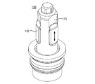
도 1은, 자동 포지셔너의 예시적인 설계가 도시된 등축도이다.
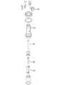
도 2는, 튜브 그리퍼 헤드의 등축도이다.
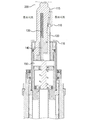
도 3은, 튜브 안에 삽입된 예시적인 튜브 그리퍼의 단면도이다.
도 4는, 예시적인 튜브 그리퍼의 확대도이다.The invention will be described in conjunction with the following drawings, wherein like reference numerals denote like elements.
1 is an isometric view showing an exemplary design of an automatic positioner.
2 is an isometric view of the tube gripper head.
3 is a cross-sectional view of an exemplary tube gripper inserted into a tube.
4 is an enlarged view of an exemplary tube gripper.
검사 및 수리 로봇이 개시되어 있다. 설계는 증기 생성기 안에서 에디 전류 테스트 프로브들의 이동 및 재위치를 위한 매우 효율적인 공간을 제공한다. 고유의 움직임 및 작은 크기는 복잡한 재위치를 위한 움직임들 없이 튜브 시트 안에서 모든 튜브들에 도달하는 데 있어서 높은 유연성을 제공한다. 이것은 목표 지역 또는 특정 튜브에 로봇의 위치시킴에 있어서 빠르고 효율적인 움직임을 제공한다. 이 모든 것은 해당 기술분야의 발전 속도 상태에서 달성된다. 대표적인 실시예에 있어서, 로봇은 튜브 시트를 큰 움직임에 대하여 분당 5 피트까지의 속도로 가로지를 수 있고, 초당 4인치까지의 테스트 또는 수리 작업 동안 튜브간 속도를 달성할 수 있다. 로봇은 부착된 도구에 대한 2차 튜브 확인을 위해 내장 머신 비전을 이용한다.Inspection and repair robots are disclosed. The design provides a very efficient space for moving and repositioning eddy current test probes within the steam generator. The inherent motion and small size provide a high degree of flexibility in reaching all the tubes in the tubesheet without movements for complex repositioning. This provides fast and efficient movement in positioning the robot in a target area or in a specific tube. All of this is achieved at the pace of development in the art. In an exemplary embodiment, the robot can traverse the tube sheet at a rate of up to 5 feet per minute for large motion and achieve inter-tube velocity during up to 4 inches of test or repair work. The robot uses built-in machine vision to identify the secondary tube for the attached tool.
로봇 몸체Robot body
도 1을 참조하면, 예시적인 0수리 및 검사 로봇은, 4개의 하우징 그리퍼(20)을 포함하는 외부 하우징(10) 및 3개의 그리퍼(50)를 가지는 회전 그리퍼 포드(40)를 포함하는 슬라이딩 몸체 부분(30)을 가진다. 슬라이딩 몸체 부분(30)은 또한 도구 헤드 잠금장치(a tool head lock)(61)를 포함하는 도구 헤드 커플링((60)을 구비하고, 도구 헤드 잠금장치(a tool head lock)(61)는 핫슈(hot shoe)(미도시), 머신 비전 조명장치(63) 및 통합된 머신 비전 카메라(64)를 구비한다. 도구 헤드 잠금장치(61)는 도구 헤드 커플링(60)에 회전 가능하게 부착되어 있다. 로봇은 외부 하우징(10) 또는 회전 그리퍼 포드(40) 중 하나로부터 튜브들로 그리퍼(20, 50)를 교대로 삽입하고 고정하는 것에 의해 튜브 시트(도시되지 않음)를 가로질러 움직인다. 이것은 3개의 중심 그리퍼(50)들이 튜브들로 삽입될 때, 외부 하우징(10)이 소정의 각으로 회전하여 슬라이딩 몸체 부분(30)과 외부 하우징(10) 사이의 슬라이딩 관계를 통해 회전 그리퍼 포드(40)로부터 벗어나 한정된 거리를 이동한다는 것을 알 수 있다. 외부 하우징(10)은 그 자체를 슬라이딩 몸체 부분(30)에 대하여 재위치시키면, 외부 하우징(10) 안의 튜브 그리퍼들(20)은 튜브들 안으로 삽입되고 고정되고, 회전 포드(40) 안의 튜브 그리퍼(50)는 튜브 시트로부터 해제되고 후퇴되어진다. 슬라이딩 몸체 부분(30)은 그때 새로운 튜브들과 결합하기 위해 외부 하우징(10)에 대하여 자유롭게 움직이게 된다. 이러한 프로세스는 하우징(10)이 튜브 시트 상의 필요한 위치에 도달할 때까지 반복된다.Referring to Figure 1, an exemplary 0 repair and inspection robot includes a sliding
4개의 외부 하우징 그리퍼들(20) 및 3개의 회전 포드 그리퍼(50)들의 구성은 사각의 넓은 범위 및 3개-피치 튜브 시트 구성, 피치 및 패턴들을 지지하도록 설계되어 있다. 몸체는 기존의 장비에 있어서 최소형의 수동 개구부(도시되지 않음)들을 통해 잘 맞도록 설계되어 있다. 로봇을 위한 컨트롤러 또한 플랫폼 공간을 최대화할 수 있도록 가능한 한 작다. 작은 반지름을 갖는 컨트롤 케이블 선은 케이블 선 얽힘을 최소화한다. The configuration of the four
튜브 시트 평면 상에 배치된 복수의 튜브 개구부들을 갖는 튜브 시트의 자동 테스트 및 자동 검사를 위한 장치로서, 코어 조립체 및 외부 하우징을 포함하고,상기 코어 조립체는 3 개의 튜브 그리퍼들을 갖는 회전 그리퍼 포드를 포함하는 슬라이딩 몸체 부분, 슬라이딩 몸체 부분(30)에 힌지 가능하게 장착되는 도구 헤드 커플링(60) 및 외부 하우징 액츄에이터들을 포함하고, 상기 외부 하우징은 좌측 및 우측 외부 하우징들을 가지며, 각 외부 하우징은 하나 이상의 튜브 그리퍼들을 포함한다.CLAIMS 1. An apparatus for automatic testing and automatic inspection of a tube sheet having a plurality of tube openings disposed on a tube sheet plane, the apparatus comprising a core assembly and an outer housing, the core assembly including a rotating gripper pod having three tube grippers A tool head coupling (60) hingably mounted to the sliding body portion (30) and outer housing actuators, the outer housing having left and right outer housings, each outer housing having one or more Tube grippers.
로봇 위치잡기Robot positioning
예시적인 실시예에 있어서, 튜브 시트 환경 외부에 호스트 컴퓨터가 있다. 또한, 튜브 시트 환경 안에 호스트 컴퓨터 및 로봇과 통신하는 외부 컨트롤러가 있다. In an exemplary embodiment, there is a host computer outside the tubesheet environment. There is also a host computer in the tube sheet environment and an external controller communicating with the robot.
호스트 컴퓨터 및 소프트웨어는 로봇의 움직임을 계획하여 컨트롤러에 명령을 보낸다. 로봇 및 컨트롤러가 동작하는 방사상 환경에서는 통상 떨어져 있다. 로봇의 외부에 있는 컨트롤러에 이더넷(Ethernet)을 통해 명령을 보낸다.The host computer and software send commands to the controller by planning the movement of the robot. It is usually off in radial environments where robots and controllers operate. It sends commands to the controller outside the robot via Ethernet.
컨트롤러는 CAN 통신 및 장비들에 전력을 전달하는 파워/데이터 선을 통해 로봇과 통신한다. 로봇은 특정 기능들을 위한 복수의 CAN 장비들을 가진다. 이것은 컨트롤러로부터 직접 명령들을 받고 실행한다.The controller communicates with the robot via power / data lines that carry power to the CAN communication and equipment. The robot has multiple CAN devices for specific functions. It receives and executes commands directly from the controller.
컨트롤러는 로봇 및 호스트 컴퓨터/소프트웨어 모두와 통신한다.The controller communicates with both the robot and the host computer / software.
한 지점으로부터 다른 지점으로 움직이는 로봇에 대한 시퀀스들은 호스트 컴퓨터에 의해 결정되고, 로봇 외부 컨트롤러에 전달된다.The sequences for a robot moving from one point to another are determined by the host computer and transmitted to the robot's external controller.
움직이게 하기 위해, 외부 컨트롤러는 특정 종류의 장비인 인수(argument) 및 장비의 어드레스를 생성한다. 이동 축에 대하여, 이것은 장비에 대한 직렬 버스 상의 어드레스와 함께 축에 대한 회전각, 회전 방향 및 회전 속도의 형태로 축 상의 모터에 대한 명령들을 포함할 수 있다. To make it move, the external controller generates an argument of the specific kind of equipment and the address of the equipment. With respect to the translation axis, this may include instructions for the motor on the axis in the form of a rotation angle, rotation direction and rotation speed relative to the axis, along with an address on the serial bus to the equipment.
호스트 컴퓨터 소프트웨어는 어떻게 콘트롤러를 움직여서 명령을 생성하는가에 대한 논리를 관리하고, 결국 그들의 형식을 상기에서 설명한 장비들에 위한 지시들로 변환하여 맞추게 된다.The host computer software manages the logic of how to move the controller to generate commands, and ultimately translates the format into instructions for the devices described above.
튜브 내부 반지름 그리퍼들Inner tube radial grippers
도 2는 예시적인 튜브 그리퍼 헤드(100)를 보여준다. 그리퍼 헤드(100)는 그리퍼 헤드(100)의 외부 벽 주위로 등간격으로 위치하는 3개의 채널들을 따라 슬라이딩하는 3개의 그리핑 고정부(110)들을 가진다. 각 채널은 그리퍼 고정부(110)에 접촉하는 경사면(115)을 가진다. 경사면(115)은 고정부(110)들이 튜브 안으로 밀어넣어질 때(도 3 참조), 로봇 몸체(10)로부터 멀어지는 방향으로, 그리퍼 헤드(100)의 중심으로부터 멀어지도록 그리퍼 고정부(110)에 힘을 가한다. 이로써, 그리퍼(20, 50)들은 자가잠금된다. 고정부(110)들이 튜브로 힘이 가해지면, 공기에 의한 압력에 의해 생성된 힘이 튜브 시트로부터 멀어지도록 그리퍼 몸체들에 힘을 가하게 되고, 이로써 튜브 벽(200)에 대하여 고정부(110)들이 힘을 가하게 된다. 로봇이 튜브 시트 아래에 있을 때, 그리퍼 헤드(100) 상에서 끌어내리는 로봇의 무게는 전원이 제거된 때조차도 튜브 벽(200)에 대하여 고정부들이 잠겨 있도록 한다. 튜브 시트가 수평이 아닐 때, 튜브로부터 멀어지는 반동력은 그리퍼(20, 50)들이 잠겨있도록 한다. 튜브들로부터 로봇을 끌어당기는 어떠한 힘이라도 그리퍼들이 제자리에 잠겨 있도록 한다. 그리퍼 고정부(110)들은 그리퍼 몸체가 튜브 벽(200)으로 약간 연장되어 고정부들(110)이 경사면(115) 후방 아래로 또한 튜브 벽(200)으로부터 멀어지도록 미는 것을 돕는 한편, 상기 고정부들을 억지로 후퇴시키는 것에 의해서만 잠금해제된다.FIG. 2 shows an exemplary
일 실시예에 있어서, 고정부(110) 면과 경사면(115) 사이의 마찰은 그리퍼 고정부 마찰 감쇄 요소(미도시)에 의해 감소된다. 그리퍼 고정부들의 작동에서 고정부(110)와 경사면(115) 사이의 마찰을 조절하여 경사평면을 가로질러 고정부(110)를 움직이는 데 필요한 힘이 튜브 벽(200)을 가로질러 고정부(110)를 움직이는 데 필요한 힘보다 적게 들도록 하는 것이 중요하다. 일 실시예에 있어서, 플라스틱 삽입부(111)는 고정부(110)와 경사면(115) 사이에 삽입된다.In one embodiment, the friction between the fixed
도 3은 튜브 벽(200)에 삽입된 그리퍼 헤드(100)가 도시된 단면도이다. 그리퍼 고정부(110)는 벽(200)에 대하여 압력을 가해진 상태를 도시하고 있고, 그리퍼 헤드(100)에서 슬롯의 경사면(115)에 의해 벽(200)으로 힘이 가해지고 있다. 예시적인 구성 있어서, 각 그리퍼 고정부(110)는 밀대(a pushrod)(120)와 접촉하고 있다. 고정부(110)를 튜브 벽(200)에 대하여 고정하기 위해, 밀대(120)는 플레이트(150)에 의해 위로 향하여 가압되고 있다. 플레이트(150)가 후퇴되어질때, 회복 핀들(140)이 적재된 스프링(130)은 밀대(120)를 아래로 향하게 하여, 그리퍼 고정부(110)에 대해 바깥으로 압력을 해제시킨다. 이미 언급한 바와 같이, 튜브 벽(200)으로부터 그리퍼 고정부(110)들을 해제시키는 데 도움을 주기 위해, 전체 그리퍼 헤드 조립체는 튜브 안으로 약간 위로 향하게 가압하여, 경사면(115)을 위로 이동시키고, 그리고 그리퍼 고정부들(110)에 대해 바깥으로 압력을 해제시킨다. 3 is a sectional view showing the
도시된 실시예는 튜브에 손상을 주지 않는 고성능 그리퍼 설계 구성으로서, (그리퍼당 300 lbs까지의) 높은 적재 능력을 제공하고, 또한 로봇에 적용되는 부하에 일치하는 고정력(grip force)을 자동적으로 제공한다. 이 모든 것은 전력 공급 방해 동안의 안전 상태(오류-방지)(fail-safe)를 유지하면서 달성된다. The illustrated embodiment is a high performance gripper design configuration that does not damage the tube, providing high loading capacity (up to 300 lbs per gripper) and automatically providing a grip force consistent with the load applied to the robot do. All of this is accomplished while maintaining a fail-safe state during power interruption.
예시적인 설계에 있어서, 로봇 튜브 그리퍼들(도 2 내지 도 4)은 이하의 특성들을 가진다. 로봇의 부하가 잠금과 잠금 유지를 돕는 자가잠금 튜브 ID 그리퍼 개념, 잠금 후퇴 스텝과 함께 그리퍼(110) 및 토우(toe, 116)의 동시 배치, 복수 단계 고객맞춤 공기 실린더 배치/해제 메커니즘, 텔리스코핑형 실린더, 동시 배치, 그러나 개별적인 견인 그리퍼 고정부(110), 개별적으로 교체가능한 그리퍼 고정부, 그리퍼 주축과 고정부 표면 사이에 미끄럼 평면을 제공하기 위한 코팅 또는 다른 마찰 감쇄 요, 홀 효과, 배치 상태를 감지하고 튜브 안의 플러그들을 감지하는 그리퍼 헤드 안의 다른 종류의 광학 센, 복수 단계 공압 잠금 그리퍼, 로봇 부하는 튜브 표면의 고정을 증가시키고, 부드러운 그리퍼 고정부(110)들은 튜브 벽(200)에 스트레스 지점을 부과하지 않고, 증기 생성기 튜브에 손상을 주지 않고, 통합된 홀 센서들은 배치 및 견인 위치를 감지하고, 전력 공급 방해 동안의 오류방지 그리퍼, 그리퍼 헤드들은 빠른 변경을 위해 설계되는 구성, 분산된 I/O 및 내장 서보 및 컨트롤 특성을 갖는다. 그리핑 및 그리핑하지 않는 작업들을 위해 튜브 직경에 있어서 변화의 조정을 위해 튜브 내부 직경 안에서 그리퍼의 최적 위치잡기를 위해 각 그리퍼의 자동적 및 개별적 조정을 한다.In an exemplary design, the robot tube grippers (Figures 2 to 4) have the following characteristics. Self-locking tube ID gripper concept that helps the load of the robot lock and maintain the lock, simultaneous placement of the gripper (110) and the toe (116) with the locking retraction step, multiple stage custom air cylinder deployment / release mechanism, Shaped cylinders, co-located, but separate tow
일 실시예에 있어서, 튜브 안에서의 그리퍼의 위치는 다양한 튜브 지름 및 개구부 오차들에 따라 적절하게 조정된다. 그리퍼가 튜브에 삽입되어야 할 때 최적의 깊이 범위가 있다. 그리퍼가 튜브에 너무 깊이 삽입되면, 추출이 어려운 것은, 그리퍼가 고정되는 위치보다는 튜브 안으로 약간 더 연장되는 이 필요하기 때문이다. 튜브의 개방단에 근접하여 그리퍼를 고정하면 어떠한 경우들에 있어서 상기 튜브에 손상을 가져올 수 있다. 따라서, 상기 그리퍼는 상기 튜브 안에 한정된 삽입 범위에 위치시키는 것이 유용하다. 이것을 달성하는 한 방법은 그리퍼에 위치 센서를 포함하는 것이다. 위치 센서는 홀 효과 센서 또는 광학 센서일 수 있다. 그리퍼는 튜브 안에 삽입되어 고정되고, 그 위치가 결정되어진다. 그리퍼가 요구된 영역에 있지 않으면, 그리퍼는 해제되어 재삽입된다. 그리퍼의 위치잡기는 2가지 타이밍 변수들의 함수이다. 그리퍼 삽입 지속시간 및 그리퍼 고정부들이 튜브 벽을 잡기 위해 외부로 힘이 가해지는 시간이다. 이들 2가지의 시간의 조합은 튜브 안에서 깊이를 달리하여 그리퍼를 배치하기 위해 조정된다. 튜브 지름 및 모양의 변화 때문에, 타이밍 변수들은 보편적이지 않다. 이러한 이유로, 본 출원서에서 설명하는 접근방법이 삽입 시간 및 고정 가동 시간을 조정하는 것에 의해 요구된 위치에 그리퍼를 배치하는 데 사용되고, 그리퍼가 튜브 안의 요구된 위치에 고정될 때까지 각 시간에서 그리퍼는 재위치된다.In one embodiment, the position of the gripper in the tube is appropriately adjusted according to various tube diameters and opening errors. There is an optimum depth range when the gripper has to be inserted into the tube. If the gripper is inserted too deeply into the tube, it is difficult to extract because it needs to extend slightly into the tube rather than where the gripper is fixed. Fixing the gripper close to the open end of the tube can cause damage to the tube in some cases. Accordingly, it is useful to place the gripper in an insertion range defined within the tube. One way to achieve this is to include a position sensor on the gripper. The position sensor may be a Hall effect sensor or an optical sensor. The gripper is inserted and fixed in the tube, and its position is determined. If the gripper is not in the requested area, the gripper is released and reinserted. Positioning of the gripper is a function of two timing parameters. Gripper insertion duration and time when gripper fixtures are externally applied to hold the tube wall. The combination of these two times is adjusted to position the gripper at different depths within the tube. Because of changes in tube diameter and shape, the timing parameters are not universal. For this reason, the approach described in the present application is used to position the gripper at the required position by adjusting the insertion time and the fixed run time, and at each time the gripper is moved to the desired position in the tube Lt; / RTI >
직렬 네트워크Serial network
일 실시예에 있어서, 직렬 네트워크는 로봇의 내부 전자 모듈들을 연결한다. 직렬 네트워크는 또한 도구 헤드에 부착된 어떠한 전자부품, 외부 컨트롤러 및 설치 로봇도 연결한다. 직렬 네트워크는 이러한 장비들 사이의 고객맞춤 배선을 필요를 제거하고 배선 수를 줄이고, 그래서 신뢰도를 높이고 비용을 감소시킨다. 직렬 네트워크의 사용은 직렬 네트워크를 단순히 이용하는 것에 의해 기존 모듈들과 통신하는 추가적인 모듈들이 부가될 수 있기 때문에 기존의 하드웨어의 확장 및 개선을 허용한다. 일 실시예에 있어서, 직렬 네트워크는 전기적 네트워크이고 산업표준 CAN 버스로 구현된다. 다른 실시예에 있어서, 직렬 네트워크는 광섬유 네트워크이다. 직렬 네트워크는 또한 단일 외부 컨트롤러가 동일 버스 상의 로봇 시스템 안의 복수의 시스템 요소들을 제어하는 것을 허용한다. 추가적인 직렬 네트워크는 시스템 레벨 항목들을 제어하고, 데이터를 저장하고 소프트웨어 작동 구성을 하는 데 사용되는 시스템 부품들에 저장된 정보를 관리하고 통신하기 위해 "1-배선(1-Wire)" 메모리 칩의 형태로 제공된다. "1-배선" 네트워크는 적절한 시스템 작동 변수들을 보장하는 것을 제공되는 것과 함께 바람직하지 않는 작동을 피하는 것이 준수되어야 한다.In one embodiment, the serial network connects the internal electronic modules of the robot. The serial network also connects any electronic components, external controllers and installation robots attached to the tool head. Serial networks eliminate the need for custom wiring between these devices and reduce the number of wires, thus increasing reliability and reducing cost. The use of a serial network allows extension and enhancement of existing hardware because additional modules communicating with existing modules can be added by simply using a serial network. In one embodiment, the serial network is an electrical network and is implemented as an industry standard CAN bus. In another embodiment, the serial network is a fiber optic network. The serial network also allows a single external controller to control multiple system components in the robotic system on the same bus. An additional serial network may be used in the form of a "1-Wire" memory chip to manage and communicate information stored in system components used to control system level items, store data, / RTI > The "1-wire" network should be adhered to to avoid undesirable operation as well as being provided to ensure proper system operating parameters.
로봇 도구 헤드Robot tool head
예시적인 설계에 있어서, 로봇 도구 헤드 커플링은 이하의 특성들을 가진다. 전기적(전원 및 신호) 연결 및 근접/홀 효과 자동잠금 특성과 조합된 빠른 공기 커플링 생성/해제 특성을 가진다.In an exemplary design, the robot tool head coupling has the following characteristics. Electrical (power and signal) connection, and fast air coupling generation / release characteristics combined with proximity / hall effect auto-locking characteristics.
제어 소프트웨어Control software
예시적인 설계를 위한 소프트웨어는 이하를 포함한다. 운동역학적 복수 로봇 조정 및 충돌 감지/회피, 소프트웨어 검사 계획 및 시뮬레이션(모사), 용기 내 작동을 유효화시키기 위한 이동경로 계획 알고리즘, 목표 위치까지의 최적 경로를 제공하기 위한 궤적 계획 알고리즘, 플러그 및 멈춤(plugs and stays)들 주위의 움직임을 제어하기 위한 이동 최적화 알고리즘 및 에디 전류 테스트 검사 및 수리 도구 전달을 최적화하기 위한 효과적인 검사 계획 알고리즘을 포함한다.The software for the exemplary design includes the following. Motion path planning algorithm to validate in - vessel operation, trajectory planning algorithm to provide optimal path to target position, plug and stop (collision detection / plugs and stays, and an effective test planning algorithm to optimize the delivery of eddy current test tests and repair tools.
특성들 및 장점들Features and Benefits
본 발명은 이하의 특징 및 장점들을 포함한다.The present invention includes the following features and advantages.
로봇의 작은 공간 차지는, 보다 작은 영역을 차지하는 한편 튜브 시트의 모든 영역들에서 효과적인 재위치잡기를 위한 궁극의 기동성을 제공하여, 헤드당 복수의 로봇들을 사용가능하게 한다. The small space occupancy of the robot allows for a plurality of robots per head, occupying a smaller area while providing ultimate maneuverability for effective repositioning in all areas of the tubesheet.
경량성. 40lbs 미만에서, 로봇은 용이하게 이동가능하고 설치 가능하다. 작은 공간차지와 함께, 튜브 시트에 고정되기 위해 보다 적은 에너지를 필요로 한다. Lightweight. Below 40 lbs, the robot is easily movable and installable. With a small space charge, less energy is required to be secured to the tubesheet.
획기적인 오류-방지 그리퍼 설계 구성은 모든 전력이 손실되더라도 로봇이 튜브 시트에 부착된 채로 있고, 긴급 상황 동안 용이하게 제거될 수 있도록 보장한다.A breakthrough fault-tolerant gripper design configuration ensures that the robot remains attached to the tubesheet even if all power is lost, and can be easily removed during an emergency.
튜브와 튜브 사이에 초당 4인치의 튜브간 속도 및 그리퍼당 300lbs 적재 능력을 갖는 빠르고 강한 로봇이다. 로봇은 고속의 검사 및 수리 도구의 적재 요구를 지지할 수 있다. It is a fast and robust robot with a tube-to-tube velocity between tubes of 4 inches per second and a loading capacity of 300 lbs per gripper. Robots can support the loading demands of high-speed inspection and repair tools.
단순화된 시스템은 CAN(Controller-area Network) 버스 조절 시스템 구조를 사용한다. 로봇은 1인치 미만의 반지름을 갖는 산업상 최소형의 로봇 선 번들(the smallest robot cable bundle)을 제공한다.The simplified system uses a controller-area network (CAN) bus control system architecture. The robot provides the industry's smallest robot cable bundle with a radius of less than one inch.
지능적인 소프트웨어 제어는 로봇이 다른 채널 헤드에서 작동하는 로봇들을 갖는 프로브 충돌들 뿐만 아니라 로봇 충돌들을 방지하기 위해 증기 생성기 안의 모든 로봇들의 원격 측정(telemetry)을 관리한다.Intelligent software control manages the telemetry of all robots in the steam generator to prevent robot collisions as well as probe collisions with robots operating on different channel heads.
제텍의 MIZ®-80iD 지능 시스템 능력을 가진 경계없는 인터페이스(seamless interface)는 하드웨어 부품 및 도구 사이의 정보 교환이 가능하게 있다.Zetek's seamless interface with MIZ®-80iD intelligent system capability enables the exchange of information between hardware components and tools.
본 발명은 특정 예들을 참조하여 상세하게 설명되었으나, 당업자에게는 본 발명의 개념을 벗어나지 않으면서 다양한 변경 및 변형이 이루어질 수 있음이 명백하다.Although the present invention has been described in detail with reference to specific examples, it will be apparent to those skilled in the art that various changes and modifications can be made without departing from the concept of the present invention.
10: 외부 하우징 20: 하우징 그리퍼
30: 슬라이딩 몸체 부분 40: 회전 그리퍼 포드
50: 그리퍼 60: 도구 헤드 커플링
61: 도구 헤드 잠금장치 63: 머신 비전 조명장치
64: 머신 비전 카메라 100: 그리퍼 헤드
110: 그리핑 고정부 115: 경사면
120: 밀대 130: 스프링
140: 회복 핀 150: 플레이트
200: 튜브 벽10: outer housing 20: housing gripper
30: sliding body portion 40: rotating gripper pod
50: gripper 60: tool head coupling
61: tool head lock device 63: machine vision light device
64: Machine vision camera 100: Gripper head
110: gripping fixing portion 115: inclined surface
120: Mouth 130: Spring
140: Recovery pin 150: Plate
200: tube wall
Claims (5)
상기 장치는:
삽입 엑츄에이터,
그리퍼 고정부들,
그리퍼 고정부 엑츄에이터, 및
위치 센서를 가지고,
상기 방법은:
상기 장비가 상기 튜브 안에 삽입되는 제1 시간 간격 동안 상기 엑츄에이터를 가동시키는 단계;
제2 시간 간격 동안 상기 그리퍼 고정부 엑츄에이터를 가동시키는 단계;
상기 튜브 안에서 상기 장치의 위치를 감지하는 단계; 및
상기 제1 및 제2 시간 간격들 중 적어도 하나에 대하여 다른 값들을 가지고, 상기 장치를 끌어당기고 상기 장치를 재삽입하는 것에 의해 상기 튜브 안에서 상기 엑츄에이터의 위치를 조정하는 단계를 포함하는 방법.
CLAIMS What is claimed is: 1. A method of adjusting an apparatus for securing an apparatus to an inner wall of a tube,
The apparatus comprises:
Insert actuator,
Grippers and governments,
A gripper fixing actuator, and
With a position sensor,
The method comprising:
Actuating the actuator during a first time interval during which the device is inserted into the tube;
Actuating the gripper fixed actuator during a second time interval;
Sensing the position of the device within the tube; And
And adjusting the position of the actuator within the tube by pulling the device and reinserting the device with different values for at least one of the first and second time intervals.
상기 포지셔너는,
a) 하우징;
b) 튜브에 결합되기 위해 하우징으로부터 연장되며 튜브 개구부 개별적으로 연장되는 모든 그리퍼를 갖추고, 모든 그리퍼가 또한 하우징을 향해 개별적으로 다시 끌어당겨질 수 있는(retractable back) 적어도 네 개의 그리퍼; 및
c) 상기 적어도 네 개의 그리퍼 중 적어도 세 개의 그리퍼가 튜브와 결합되고 그리퍼 중 적어도 하나가 또 다른 튜브로부터 끌어당겨질 때 이동가능하여, 하우징이 이동에 의해서 튜브 어레이에 대해 이동되고 재위치될 수 있는 하우징을 포함하는 로봇 도구 포지셔너.
1. A robot tool positioner for positioning test and repair equipment in a tube array having a plurality of tube openings,
The positioner includes:
a) a housing;
b) at least four grippers extending from the housing for engagement with the tube, each gripper having all of the tube openings individually extended, and all grippers also retractable individually back towards the housing; And
c) at least three of the at least four grippers are engageable with the tube and moveable when at least one of the grippers is pulled from another tube such that the housing can be moved relative to the tube array by movement and repositioned, A robot tool positioner.
모든 그리퍼가 슬라이드식으로(slidably) 연장가능하며 슬라이드식으로 끌어당겨질 수 있는 로봇 도구 포지셔너.
3. The method of claim 2,
A robot tool positioner where all grippers can be slidably extended and pulled in a sliding manner.
하우징이 그리퍼 중 적어도 하나에 대해서 이동가능한 로봇 도구 포지셔너.
3. The method of claim 2,
A robot tool positioner in which the housing is movable relative to at least one of the grippers.
적어도 네 개의 그리퍼 중 네 개의 그리퍼가 튜브에 결합될 때 하우징이 그리퍼 중 적어도 하나에 대해서 이동가능한 로봇 도구 포지셔너.3. The method of claim 2,
Wherein the housing is movable relative to at least one of the grippers when four of the at least four grippers are coupled to the tube.
Applications Claiming Priority (3)
| Application Number | Priority Date | Filing Date | Title |
|---|---|---|---|
| US14562909P | 2009-01-19 | 2009-01-19 | |
| US61/145,629 | 2009-01-19 | ||
| PCT/US2010/021407 WO2010083521A2 (en) | 2009-01-19 | 2010-01-19 | Apparatus for automated positioning of eddy current test probe |
Related Parent Applications (1)
| Application Number | Title | Priority Date | Filing Date |
|---|---|---|---|
| KR1020117019217A Division KR101894596B1 (en) | 2009-01-19 | 2010-01-19 | Apparatus for automated positioning of eddy current test probe |
Publications (2)
| Publication Number | Publication Date |
|---|---|
| KR20180098684A true KR20180098684A (en) | 2018-09-04 |
| KR102081528B1 KR102081528B1 (en) | 2020-02-25 |
Family
ID=42336330
Family Applications (3)
| Application Number | Title | Priority Date | Filing Date |
|---|---|---|---|
| KR1020187024283A Active KR102081528B1 (en) | 2009-01-19 | 2010-01-19 | Apparatus for automated positioning of eddy current test probe |
| KR1020177009662A Active KR102110018B1 (en) | 2009-01-19 | 2010-01-19 | Apparatus for automated positioning of eddy current test probe |
| KR1020117019217A Active KR101894596B1 (en) | 2009-01-19 | 2010-01-19 | Apparatus for automated positioning of eddy current test probe |
Family Applications After (2)
| Application Number | Title | Priority Date | Filing Date |
|---|---|---|---|
| KR1020177009662A Active KR102110018B1 (en) | 2009-01-19 | 2010-01-19 | Apparatus for automated positioning of eddy current test probe |
| KR1020117019217A Active KR101894596B1 (en) | 2009-01-19 | 2010-01-19 | Apparatus for automated positioning of eddy current test probe |
Country Status (9)
| Country | Link |
|---|---|
| US (3) | US8746089B2 (en) |
| EP (2) | EP2389538B1 (en) |
| JP (1) | JP5676479B2 (en) |
| KR (3) | KR102081528B1 (en) |
| CN (1) | CN102388266B (en) |
| CA (2) | CA2750221C (en) |
| ES (2) | ES2728721T3 (en) |
| SI (2) | SI2389538T1 (en) |
| WO (1) | WO2010083521A2 (en) |
Families Citing this family (19)
| Publication number | Priority date | Publication date | Assignee | Title |
|---|---|---|---|---|
| JP2012042185A (en) * | 2010-08-23 | 2012-03-01 | Mitsubishi Heavy Ind Ltd | Clamper, and in-water-chamber operation device |
| US8278779B2 (en) | 2011-02-07 | 2012-10-02 | General Electric Company | System and method for providing redundant power to a device |
| CN102649274A (en) * | 2011-02-25 | 2012-08-29 | 富泰华工业(深圳)有限公司 | Robot claw and robot adopting same |
| GB2522472B (en) * | 2014-01-27 | 2017-09-06 | Epsilon Optics Aerospace Ltd | A method and apparatus for a structural monitoring device adapted to be locatable within a tubular structure |
| CN104249368B (en) * | 2014-09-09 | 2016-06-01 | 上海交通大学 | Double columnar form Self-Reconfigurable Modular Robot |
| WO2016083897A2 (en) * | 2014-11-24 | 2016-06-02 | Kitov Systems Ltd. | Automated inspection |
| US9894199B1 (en) | 2016-04-05 | 2018-02-13 | State Farm Mutual Automobile Insurance Company | Systems and methods for authenticating a caller at a call center |
| CN105945962B (en) * | 2016-05-19 | 2018-01-30 | 哈尔滨工业大学 | Articulated type climbing robot for the detection of steam generator heat pipe |
| DE102016013247A1 (en) * | 2016-11-08 | 2018-05-09 | Westinghouse Electric Germany Gmbh | Drilling device for processing pipes on tube sheets in a radioactive environment |
| DE102016013245B4 (en) | 2016-11-08 | 2025-10-16 | Westinghouse Electric Germany Gmbh | Drilling rig for processing pipes in radioactive environments |
| EP3592493A4 (en) * | 2017-03-08 | 2020-12-02 | BWXT Nuclear Energy, Inc. | DEVICE AND METHOD FOR REPAIRING GUIDE PLATE BOLTS |
| CN106970146B (en) * | 2017-03-28 | 2020-02-21 | 哈尔滨工业大学 | A positioning connection mechanism of a steam generator heat transfer tube detection equipment |
| US11112382B2 (en) * | 2018-03-21 | 2021-09-07 | Infrastructure Preservation Corporation | Robotic magnetic flux inspection system for bridge wire rope suspender cables |
| US20220260529A1 (en) * | 2019-03-21 | 2022-08-18 | Infrastructure Preservation Corporation | Robotic magnetic flux inspection system for broadcast tower support cables |
| FR3095274B1 (en) * | 2019-04-19 | 2021-04-02 | Framatome Sa | Device for checking a weld of a hollow longitudinal tubular element |
| CN112066158A (en) * | 2019-12-10 | 2020-12-11 | 天目爱视(北京)科技有限公司 | Intelligent pipeline robot |
| CN111717609A (en) * | 2020-05-13 | 2020-09-29 | 中核武汉核电运行技术股份有限公司 | Carrying platform and control method for steam generator tube sheet maintenance |
| CN111458404A (en) * | 2020-05-20 | 2020-07-28 | 四川纽赛特工业机器人制造有限公司 | Automatic change pipe fitting test center |
| CN112945507B (en) * | 2021-02-03 | 2023-05-19 | 中国空气动力研究与发展中心高速空气动力研究所 | Hypersonic wind tunnel axisymmetric spray pipe |
Citations (1)
| Publication number | Priority date | Publication date | Assignee | Title |
|---|---|---|---|---|
| KR20050029231A (en) * | 2002-07-22 | 2005-03-24 | 웨스팅하우스 일레트릭 캄파니 엘엘씨 | Miniature manipulator for servicing the interior of nuclear steam generator tubes |
Family Cites Families (45)
| Publication number | Priority date | Publication date | Assignee | Title |
|---|---|---|---|---|
| US2865640A (en) * | 1955-12-21 | 1958-12-23 | Exxon Research Engineering Co | Tube holding apparatus |
| DE1627286C3 (en) * | 1967-09-14 | 1973-01-18 | Schmid & Wezel | Hand-held device with reciprocating tool |
| US3495546A (en) * | 1967-11-03 | 1970-02-17 | American Mach & Foundry | Speed control device for pipeline inspection apparatus |
| US3913752A (en) * | 1973-08-01 | 1975-10-21 | Combustion Eng | Remotely movable platform |
| US3889820A (en) * | 1973-08-01 | 1975-06-17 | Combustion Eng | Method and apparatus for suspendedly supporting a platform |
| JPS5157489A (en) * | 1974-11-15 | 1976-05-19 | Mitsubishi Heavy Ind Ltd | Jidokensasochino kontorooruhoho |
| FR2309314A1 (en) * | 1974-12-05 | 1976-11-26 | Framatome Sa | DEVICE FOR SELECTIVE POSITIONING OF AN ORGAN ON A TUBULAR PLATE |
| CA1014724A (en) | 1975-03-11 | 1977-08-02 | Peter D. Stevens-Guille | Locating test probes in heat exchanger tubes |
| US4018346A (en) * | 1975-11-18 | 1977-04-19 | Combustion Engineering, Inc. | Mounting arrangement for anchor fingers on a surface traversing apparatus |
| US4018345A (en) * | 1975-11-18 | 1977-04-19 | Combustion Engineering, Inc. | Surface traversing apparatus |
| US4074814A (en) * | 1976-03-26 | 1978-02-21 | Combustion Engineering, Inc. | Method and apparatus for controlling surface traversing device |
| US4193735A (en) * | 1978-04-24 | 1980-03-18 | Combustion Engineering, Inc. | Work table for a stepped platform |
| GB2039268B (en) * | 1978-12-15 | 1983-01-19 | Exxon Research Engineering Co | Metal extraction by solid-liquid agglomerates |
| FR2448143A1 (en) * | 1979-02-05 | 1980-08-29 | Intercontrole Sa | METHOD AND DEVICE FOR REMOVING A PROBE HOLDER FROM THE LOWER CHAMBER OF A VERTICAL TUBULAR HEAT EXCHANGER |
| FR2503920B1 (en) * | 1981-04-08 | 1987-08-21 | Intercontrole Sa | DEVICE FOR POSITIONING A MEMBER OPPOSING THE PERFORATIONS OF A PLATE |
| FR2503921A1 (en) * | 1981-04-10 | 1982-10-15 | Commissariat Energie Atomique | DEVICE FOR POSITIONING A BODY INTO PERFORATIONS OF A PLATE AND METHOD FOR REMOTELY MOUNTING SUCH A DEVICE |
| FR2513927A1 (en) * | 1981-10-05 | 1983-04-08 | Framatome Sa | TELE-MANIPULATOR FOR INTERVENTION IN A STEAM GENERATOR WATER BOX |
| US4449599A (en) * | 1982-09-27 | 1984-05-22 | Combustion Engineering, Inc. | Finger walker for tube sheet |
| JPS5997864A (en) | 1982-11-29 | 1984-06-05 | 三菱重工業株式会社 | Intermittent shifter for work |
| US4688327A (en) * | 1983-10-03 | 1987-08-25 | Westinghouse Electric Corp. | Sleeving of tubes of steam generator |
| US4597294A (en) * | 1984-06-25 | 1986-07-01 | Westinghouse Electric Corp. | Ultrasonic nondestructive tubing inspection system |
| DE3509177C1 (en) * | 1985-03-14 | 1986-10-02 | Brown Boveri Reaktor GmbH, 6800 Mannheim | Device for introducing a cylindrical body, in particular a sleeve, into a tube of a steam generator |
| JPH086894B2 (en) | 1985-03-22 | 1996-01-29 | 株式会社日立製作所 | Heat exchanger Water chamber work Robot movement / holding device |
| US4702878A (en) * | 1986-01-15 | 1987-10-27 | Westinghouse Electric Corp. | Search and retrieval device |
| JPS6344162A (en) * | 1986-08-11 | 1988-02-25 | Kubota Ltd | Cracking detector for suction roll shell |
| US4720902A (en) * | 1986-12-22 | 1988-01-26 | Carrier Corporation | One step tension expander and method of using |
| US4829648A (en) * | 1987-01-27 | 1989-05-16 | Westinghouse Electric Corp. | Apparatus and method for simultaneously loading a reinforcing sleeve and mandrel into a tube |
| JPH073333B2 (en) * | 1988-01-28 | 1995-01-18 | 住友ゴム工業株式会社 | Method and device for detecting defective joint portion of elastic sheet |
| US4872524A (en) * | 1988-04-13 | 1989-10-10 | Oconnor Chadwell | Wheel-less walking dolly |
| FR2644568B1 (en) * | 1989-03-16 | 1991-07-05 | Intercontrole Sa | INTERVENTION DEVICE, PARTICULARLY FOR CHECKING, INSPECTING AND MAINTAINING HEAT EXCHANGERS |
| FR2645328B1 (en) * | 1989-04-04 | 1991-07-19 | Framatome Sa | DEVICE FOR CENTERING AN INTERVENTION TOOL IN A STEAM GENERATOR TUBE |
| JPH0333651A (en) * | 1989-06-30 | 1991-02-13 | Chubu Electric Power Co Inc | Automatic inspection apparatus |
| US5355063A (en) * | 1990-11-01 | 1994-10-11 | Westinghouse Electric Corp. | Robotic system for servicing the heat exchanger tubes of a nuclear steam generator |
| FR2674938B1 (en) | 1991-04-05 | 1993-07-30 | Barras Provence | VEHICLE FOR EXPLORING AND MAINTAINING A TUBE NETWORK OF A STEAM GENERATOR. |
| US6672257B1 (en) * | 1994-05-06 | 2004-01-06 | Foster-Miller, Inc. | Upper bundle steam generator cleaning system and method |
| US5890553A (en) * | 1996-08-01 | 1999-04-06 | California Institute Of Technology | Multifunction automated crawling system |
| DE29700027U1 (en) | 1997-01-02 | 1998-04-30 | Siemens AG, 80333 München | Test manipulator for eddy current and ultrasonic testing of hollow cylindrical nuclear reactor components, in particular control rod drive housings |
| AUPO724797A0 (en) * | 1997-06-06 | 1997-07-03 | Down Hole Technologies Pty Ltd | Retrieval head for a drill bit composed of a plurality of bit segments |
| JPH11174032A (en) * | 1997-12-10 | 1999-07-02 | Toshiba Corp | Inspection apparatus and method for intermediate heat exchanger |
| TW463028B (en) * | 1998-04-21 | 2001-11-11 | Hitachi Shipbuilding Eng Co | Working robot for heat exchangers and operating method thereof |
| US6450104B1 (en) * | 2000-04-28 | 2002-09-17 | North Carolina State University | Modular observation crawler and sensing instrument and method for operating same |
| US7909120B2 (en) * | 2005-05-03 | 2011-03-22 | Noetic Technologies Inc. | Gripping tool |
| JP2008089328A (en) | 2006-09-29 | 2008-04-17 | Hitachi Ltd | Eddy current flaw detector and eddy current flaw detection method |
| US7896111B2 (en) * | 2007-12-10 | 2011-03-01 | Noetic Technologies Inc. | Gripping tool with driven screw grip activation |
| US8317455B2 (en) * | 2009-11-11 | 2012-11-27 | Peinemann Equipment B.V. | Device and method for removing a bundle from a heat exchanger |
-
2010
- 2010-01-14 US US12/687,261 patent/US8746089B2/en active Active
- 2010-01-19 SI SI201031325A patent/SI2389538T1/en unknown
- 2010-01-19 EP EP10700929.2A patent/EP2389538B1/en active Active
- 2010-01-19 KR KR1020187024283A patent/KR102081528B1/en active Active
- 2010-01-19 ES ES16183475T patent/ES2728721T3/en active Active
- 2010-01-19 EP EP16183475.9A patent/EP3163161B1/en active Active
- 2010-01-19 CN CN201080011051.4A patent/CN102388266B/en active Active
- 2010-01-19 ES ES10700929.2T patent/ES2605227T3/en active Active
- 2010-01-19 JP JP2011546426A patent/JP5676479B2/en active Active
- 2010-01-19 WO PCT/US2010/021407 patent/WO2010083521A2/en not_active Ceased
- 2010-01-19 SI SI201031881T patent/SI3163161T1/en unknown
- 2010-01-19 CA CA2750221A patent/CA2750221C/en active Active
- 2010-01-19 KR KR1020177009662A patent/KR102110018B1/en active Active
- 2010-01-19 CA CA2967589A patent/CA2967589C/en active Active
- 2010-01-19 KR KR1020117019217A patent/KR101894596B1/en active Active
-
2013
- 2013-08-09 US US13/963,630 patent/US9273985B2/en active Active
-
2016
- 2016-02-26 US US15/055,178 patent/US20160176685A1/en not_active Abandoned
Patent Citations (1)
| Publication number | Priority date | Publication date | Assignee | Title |
|---|---|---|---|---|
| KR20050029231A (en) * | 2002-07-22 | 2005-03-24 | 웨스팅하우스 일레트릭 캄파니 엘엘씨 | Miniature manipulator for servicing the interior of nuclear steam generator tubes |
Also Published As
| Publication number | Publication date |
|---|---|
| CA2967589A1 (en) | 2010-07-22 |
| CA2750221C (en) | 2017-07-04 |
| CA2750221A1 (en) | 2010-07-22 |
| EP3163161A3 (en) | 2017-06-21 |
| CN102388266A (en) | 2012-03-21 |
| US9273985B2 (en) | 2016-03-01 |
| CA2967589C (en) | 2019-06-25 |
| KR101894596B1 (en) | 2018-10-04 |
| EP2389538A2 (en) | 2011-11-30 |
| US20140033837A1 (en) | 2014-02-06 |
| JP5676479B2 (en) | 2015-02-25 |
| ES2605227T3 (en) | 2017-03-13 |
| ES2728721T3 (en) | 2019-10-28 |
| KR102081528B1 (en) | 2020-02-25 |
| EP3163161A2 (en) | 2017-05-03 |
| SI2389538T1 (en) | 2017-04-26 |
| US20100181791A1 (en) | 2010-07-22 |
| EP2389538B1 (en) | 2016-08-10 |
| CN102388266B (en) | 2014-12-03 |
| WO2010083521A2 (en) | 2010-07-22 |
| WO2010083521A3 (en) | 2011-09-29 |
| KR20110121687A (en) | 2011-11-08 |
| US20160176685A1 (en) | 2016-06-23 |
| US8746089B2 (en) | 2014-06-10 |
| EP3163161B1 (en) | 2019-03-13 |
| KR20170045358A (en) | 2017-04-26 |
| JP2012515895A (en) | 2012-07-12 |
| KR102110018B1 (en) | 2020-05-13 |
| SI3163161T1 (en) | 2019-08-30 |
Similar Documents
| Publication | Publication Date | Title |
|---|---|---|
| KR101894596B1 (en) | Apparatus for automated positioning of eddy current test probe | |
| EP1523395B1 (en) | Miniature manipulator for servicing the interior of nuclear steam generator tubes | |
| CN110769959B (en) | Apparatus and method for blind bolt repair | |
| WO2008063303A2 (en) | Collimator changer | |
| EP0836694B1 (en) | Movable robot for internal inspection of pipes | |
| JP2012515895A5 (en) | ||
| WO2018013899A1 (en) | Tube sheet inspection robot | |
| US20060017237A1 (en) | Bayonet collet pickup tool for agile fixturing | |
| US12202126B2 (en) | Articulated manipulator for navigating and servicing a heat exchanger | |
| Qiu et al. | Research on the Automatic Exchange Technology for Space Robot Manipulators |
Legal Events
| Date | Code | Title | Description |
|---|---|---|---|
| A107 | Divisional application of patent | ||
| A201 | Request for examination | ||
| PA0104 | Divisional application for international application |
St.27 status event code: A-0-1-A10-A18-div-PA0104 St.27 status event code: A-0-1-A10-A16-div-PA0104 |
|
| PA0201 | Request for examination |
St.27 status event code: A-1-2-D10-D11-exm-PA0201 |
|
| PG1501 | Laying open of application |
St.27 status event code: A-1-1-Q10-Q12-nap-PG1501 |
|
| E902 | Notification of reason for refusal | ||
| PE0902 | Notice of grounds for rejection |
St.27 status event code: A-1-2-D10-D21-exm-PE0902 |
|
| R17-X000 | Change to representative recorded |
St.27 status event code: A-3-3-R10-R17-oth-X000 |
|
| T11-X000 | Administrative time limit extension requested |
St.27 status event code: U-3-3-T10-T11-oth-X000 |
|
| T11-X000 | Administrative time limit extension requested |
St.27 status event code: U-3-3-T10-T11-oth-X000 |
|
| T11-X000 | Administrative time limit extension requested |
St.27 status event code: U-3-3-T10-T11-oth-X000 |
|
| AMND | Amendment | ||
| P11-X000 | Amendment of application requested |
St.27 status event code: A-2-2-P10-P11-nap-X000 |
|
| P13-X000 | Application amended |
St.27 status event code: A-2-2-P10-P13-nap-X000 |
|
| E601 | Decision to refuse application | ||
| PE0601 | Decision on rejection of patent |
St.27 status event code: N-2-6-B10-B15-exm-PE0601 |
|
| X091 | Application refused [patent] | ||
| T11-X000 | Administrative time limit extension requested |
St.27 status event code: U-3-3-T10-T11-oth-X000 |
|
| T13-X000 | Administrative time limit extension granted |
St.27 status event code: U-3-3-T10-T13-oth-X000 |
|
| T11-X000 | Administrative time limit extension requested |
St.27 status event code: U-3-3-T10-T11-oth-X000 |
|
| T13-X000 | Administrative time limit extension granted |
St.27 status event code: U-3-3-T10-T13-oth-X000 |
|
| AMND | Amendment | ||
| P11-X000 | Amendment of application requested |
St.27 status event code: A-2-2-P10-P11-nap-X000 |
|
| P13-X000 | Application amended |
St.27 status event code: A-2-2-P10-P13-nap-X000 |
|
| PX0901 | Re-examination |
St.27 status event code: A-2-3-E10-E12-rex-PX0901 |
|
| R17-X000 | Change to representative recorded |
St.27 status event code: A-3-3-R10-R17-oth-X000 |
|
| PX0701 | Decision of registration after re-examination |
St.27 status event code: A-3-4-F10-F13-rex-PX0701 |
|
| X701 | Decision to grant (after re-examination) | ||
| R18-X000 | Changes to party contact information recorded |
St.27 status event code: A-3-3-R10-R18-oth-X000 |
|
| GRNT | Written decision to grant | ||
| PR0701 | Registration of establishment |
St.27 status event code: A-2-4-F10-F11-exm-PR0701 |
|
| PR1002 | Payment of registration fee |
St.27 status event code: A-2-2-U10-U12-oth-PR1002 Fee payment year number: 1 |
|
| PG1601 | Publication of registration |
St.27 status event code: A-4-4-Q10-Q13-nap-PG1601 |
|
| PR1001 | Payment of annual fee |
St.27 status event code: A-4-4-U10-U11-oth-PR1001 Fee payment year number: 4 |
|
| PR1001 | Payment of annual fee |
St.27 status event code: A-4-4-U10-U11-oth-PR1001 Fee payment year number: 5 |
|
| PR1001 | Payment of annual fee |
St.27 status event code: A-4-4-U10-U11-oth-PR1001 Fee payment year number: 6 |
|
| PR1001 | Payment of annual fee |
St.27 status event code: A-4-4-U10-U11-oth-PR1001 Fee payment year number: 7 |
|
| U11 | Full renewal or maintenance fee paid |
Free format text: ST27 STATUS EVENT CODE: A-4-4-U10-U11-OTH-PR1001 (AS PROVIDED BY THE NATIONAL OFFICE) Year of fee payment: 7 |