EP2389538B1 - Apparatus for automated positioning of eddy current test probe - Google Patents
Apparatus for automated positioning of eddy current test probe Download PDFInfo
- Publication number
- EP2389538B1 EP2389538B1 EP10700929.2A EP10700929A EP2389538B1 EP 2389538 B1 EP2389538 B1 EP 2389538B1 EP 10700929 A EP10700929 A EP 10700929A EP 2389538 B1 EP2389538 B1 EP 2389538B1
- Authority
- EP
- European Patent Office
- Prior art keywords
- tube
- gripper
- gripper shoe
- grippers
- tube sheet
- Prior art date
- Legal status (The legal status is an assumption and is not a legal conclusion. Google has not performed a legal analysis and makes no representation as to the accuracy of the status listed.)
- Active
Links
- 238000012360 testing method Methods 0.000 title claims description 16
- 239000000523 sample Substances 0.000 title claims description 9
- 230000008439 repair process Effects 0.000 claims description 12
- 238000007689 inspection Methods 0.000 claims description 9
- 238000003780 insertion Methods 0.000 claims description 7
- 230000037431 insertion Effects 0.000 claims description 7
- 230000008878 coupling Effects 0.000 claims description 6
- 238000010168 coupling process Methods 0.000 claims description 6
- 238000005859 coupling reaction Methods 0.000 claims description 6
- 238000004891 communication Methods 0.000 claims description 3
- 230000013011 mating Effects 0.000 claims 6
- 239000003638 chemical reducing agent Substances 0.000 claims 4
- 230000003213 activating effect Effects 0.000 claims 2
- 230000033001 locomotion Effects 0.000 description 10
- 238000013461 design Methods 0.000 description 8
- 230000005355 Hall effect Effects 0.000 description 4
- 238000009434 installation Methods 0.000 description 3
- 230000008901 benefit Effects 0.000 description 2
- 230000006870 function Effects 0.000 description 2
- 238000012423 maintenance Methods 0.000 description 2
- 230000003287 optical effect Effects 0.000 description 2
- 239000011295 pitch Substances 0.000 description 2
- 230000009467 reduction Effects 0.000 description 2
- 230000004308 accommodation Effects 0.000 description 1
- 230000003044 adaptive effect Effects 0.000 description 1
- 238000004873 anchoring Methods 0.000 description 1
- 238000013459 approach Methods 0.000 description 1
- 238000003491 array Methods 0.000 description 1
- 230000008859 change Effects 0.000 description 1
- 238000000576 coating method Methods 0.000 description 1
- 238000005202 decontamination Methods 0.000 description 1
- 230000003588 decontaminative effect Effects 0.000 description 1
- 238000001514 detection method Methods 0.000 description 1
- 238000004033 diameter control Methods 0.000 description 1
- 238000000605 extraction Methods 0.000 description 1
- 239000000835 fiber Substances 0.000 description 1
- 230000006872 improvement Effects 0.000 description 1
- 230000010354 integration Effects 0.000 description 1
- 230000007246 mechanism Effects 0.000 description 1
- 238000000034 method Methods 0.000 description 1
- 238000012986 modification Methods 0.000 description 1
- 230000004048 modification Effects 0.000 description 1
- 238000005457 optimization Methods 0.000 description 1
- 230000008569 process Effects 0.000 description 1
- 230000002285 radioactive effect Effects 0.000 description 1
- 238000010079 rubber tapping Methods 0.000 description 1
- 238000004088 simulation Methods 0.000 description 1
- 238000012795 verification Methods 0.000 description 1
Images


Classifications
-
- B—PERFORMING OPERATIONS; TRANSPORTING
- B66—HOISTING; LIFTING; HAULING
- B66C—CRANES; LOAD-ENGAGING ELEMENTS OR DEVICES FOR CRANES, CAPSTANS, WINCHES, OR TACKLES
- B66C1/00—Load-engaging elements or devices attached to lifting or lowering gear of cranes or adapted for connection therewith for transmitting lifting forces to articles or groups of articles
- B66C1/10—Load-engaging elements or devices attached to lifting or lowering gear of cranes or adapted for connection therewith for transmitting lifting forces to articles or groups of articles by mechanical means
- B66C1/42—Gripping members engaging only the external or internal surfaces of the articles
- B66C1/44—Gripping members engaging only the external or internal surfaces of the articles and applying frictional forces
- B66C1/54—Internally-expanding grippers for handling hollow articles
-
- B—PERFORMING OPERATIONS; TRANSPORTING
- B25—HAND TOOLS; PORTABLE POWER-DRIVEN TOOLS; MANIPULATORS
- B25J—MANIPULATORS; CHAMBERS PROVIDED WITH MANIPULATION DEVICES
- B25J15/00—Gripping heads and other end effectors
-
- B—PERFORMING OPERATIONS; TRANSPORTING
- B66—HOISTING; LIFTING; HAULING
- B66C—CRANES; LOAD-ENGAGING ELEMENTS OR DEVICES FOR CRANES, CAPSTANS, WINCHES, OR TACKLES
- B66C1/00—Load-engaging elements or devices attached to lifting or lowering gear of cranes or adapted for connection therewith for transmitting lifting forces to articles or groups of articles
- B66C1/10—Load-engaging elements or devices attached to lifting or lowering gear of cranes or adapted for connection therewith for transmitting lifting forces to articles or groups of articles by mechanical means
- B66C1/42—Gripping members engaging only the external or internal surfaces of the articles
- B66C1/44—Gripping members engaging only the external or internal surfaces of the articles and applying frictional forces
- B66C1/54—Internally-expanding grippers for handling hollow articles
- B66C1/56—Internally-expanding grippers for handling hollow articles for handling tubes
-
- F—MECHANICAL ENGINEERING; LIGHTING; HEATING; WEAPONS; BLASTING
- F22—STEAM GENERATION
- F22B—METHODS OF STEAM GENERATION; STEAM BOILERS
- F22B37/00—Component parts or details of steam boilers
- F22B37/002—Component parts or details of steam boilers specially adapted for nuclear steam generators, e.g. maintenance, repairing or inspecting equipment not otherwise provided for
- F22B37/003—Maintenance, repairing or inspecting equipment positioned in or via the headers
- F22B37/005—Positioning apparatus specially adapted therefor
-
- F—MECHANICAL ENGINEERING; LIGHTING; HEATING; WEAPONS; BLASTING
- F22—STEAM GENERATION
- F22B—METHODS OF STEAM GENERATION; STEAM BOILERS
- F22B37/00—Component parts or details of steam boilers
- F22B37/002—Component parts or details of steam boilers specially adapted for nuclear steam generators, e.g. maintenance, repairing or inspecting equipment not otherwise provided for
- F22B37/006—Walking equipment, e.g. walking platforms suspended at the tube sheet
-
- G—PHYSICS
- G01—MEASURING; TESTING
- G01D—MEASURING NOT SPECIALLY ADAPTED FOR A SPECIFIC VARIABLE; ARRANGEMENTS FOR MEASURING TWO OR MORE VARIABLES NOT COVERED IN A SINGLE OTHER SUBCLASS; TARIFF METERING APPARATUS; MEASURING OR TESTING NOT OTHERWISE PROVIDED FOR
- G01D11/00—Component parts of measuring arrangements not specially adapted for a specific variable
- G01D11/30—Supports specially adapted for an instrument; Supports specially adapted for a set of instruments
-
- G—PHYSICS
- G01—MEASURING; TESTING
- G01M—TESTING STATIC OR DYNAMIC BALANCE OF MACHINES OR STRUCTURES; TESTING OF STRUCTURES OR APPARATUS, NOT OTHERWISE PROVIDED FOR
- G01M5/00—Investigating the elasticity of structures, e.g. deflection of bridges or air-craft wings
- G01M5/0025—Investigating the elasticity of structures, e.g. deflection of bridges or air-craft wings of elongated objects, e.g. pipes, masts, towers or railways
-
- G—PHYSICS
- G01—MEASURING; TESTING
- G01M—TESTING STATIC OR DYNAMIC BALANCE OF MACHINES OR STRUCTURES; TESTING OF STRUCTURES OR APPARATUS, NOT OTHERWISE PROVIDED FOR
- G01M5/00—Investigating the elasticity of structures, e.g. deflection of bridges or air-craft wings
- G01M5/0033—Investigating the elasticity of structures, e.g. deflection of bridges or air-craft wings by determining damage, crack or wear
-
- G—PHYSICS
- G01—MEASURING; TESTING
- G01M—TESTING STATIC OR DYNAMIC BALANCE OF MACHINES OR STRUCTURES; TESTING OF STRUCTURES OR APPARATUS, NOT OTHERWISE PROVIDED FOR
- G01M5/00—Investigating the elasticity of structures, e.g. deflection of bridges or air-craft wings
- G01M5/0091—Investigating the elasticity of structures, e.g. deflection of bridges or air-craft wings by using electromagnetic excitation or detection
-
- G—PHYSICS
- G01—MEASURING; TESTING
- G01N—INVESTIGATING OR ANALYSING MATERIALS BY DETERMINING THEIR CHEMICAL OR PHYSICAL PROPERTIES
- G01N27/00—Investigating or analysing materials by the use of electric, electrochemical, or magnetic means
- G01N27/72—Investigating or analysing materials by the use of electric, electrochemical, or magnetic means by investigating magnetic variables
- G01N27/82—Investigating or analysing materials by the use of electric, electrochemical, or magnetic means by investigating magnetic variables for investigating the presence of flaws
- G01N27/90—Investigating or analysing materials by the use of electric, electrochemical, or magnetic means by investigating magnetic variables for investigating the presence of flaws using eddy currents
- G01N27/9013—Arrangements for scanning
- G01N27/902—Arrangements for scanning by moving the sensors
-
- Y—GENERAL TAGGING OF NEW TECHNOLOGICAL DEVELOPMENTS; GENERAL TAGGING OF CROSS-SECTIONAL TECHNOLOGIES SPANNING OVER SEVERAL SECTIONS OF THE IPC; TECHNICAL SUBJECTS COVERED BY FORMER USPC CROSS-REFERENCE ART COLLECTIONS [XRACs] AND DIGESTS
- Y10—TECHNICAL SUBJECTS COVERED BY FORMER USPC
- Y10T—TECHNICAL SUBJECTS COVERED BY FORMER US CLASSIFICATION
- Y10T29/00—Metal working
- Y10T29/51—Plural diverse manufacturing apparatus including means for metal shaping or assembling
- Y10T29/5199—Work on tubes
Definitions
- Tube sheets are arrays of parallel tubes that can be accessed at at least one end wherein the tube ends are arranged in an single plane. Testing of each tube is delicate and time consuming. In the past, this has been done by manually placing testing probes in the tubes. Described herein is an improved automated apparatus for positioning test and repair equipment in a tube sheet for steam generators.
- Desirable attributes of such an automated apparatus include: single person fast installation; integrated grab features for handling; protection bumpers ; independent of tube sheet and steam generator features; simplified cable systems and single point cable connection; simplified calibration; ease of decontamination; complete integration with data acquisition systems; fast, accurate performance; and support for repair tooling.
- WO 2004/009287 A1 discloses a miniature manipulator for servicing the interior of nuclear steam generator tubes including a base member, a block member and a foot member.
- the base member has at least one gripper for gripping a tube extending through a tube sheet.
- the block member is connected to the base member for a linear movement and rotation relative to the base member.
- the foot member is connected to the block member for a linear movement relative to the block member.
- the present invention relates to automatic inspection and repair systems and more particularly to a robotic apparatus for positioning an eddy current test probe in an array of steam generator tubes.
- An apparatus for automated inspection and testing of a tube sheet in particular a robotic tool positioner especially adapted for positioning tooling and testing equipment in a tube array, such as in a steam generator, comprising the features of claim 1.
- the tool positioner has several novel features, described herein.
- the tool positioner is adapted to move across the face of a tube sheet of open tubes.
- the positioner includes: a sliding body portion containing a rotating gripper pod with the rotating gripper pod having at least one tube gripper; left and right outer housing portions having at least one tube gripper each; and a tool head coupler to support various attachments, including an eddy current test probe, repair and maintenance tools.
- the sliding body portion moves laterally across the tube sheet with respect to the housing portion.
- the rotating gripper pod allows the positioner to rotate in an axis perpendicular to the plane of the tube sheet.
- the tool head coupler provides for the attachment of test probes and repair and maintenance tools to the sliding body portion.
- the robot also includes machine vision and machine vision lighting.
- the tube grippers have a pneumatic actuator, at least one gripper shoes and integrated sensors adapted to detect deployment and retraction position.
- the sensors are Hall effect sensors.
- the tube grippers are adapted so that the reactionary force of the tool positioner pulling away from the tube sheet forces the tube gripper shoes against the tube wall.
- the gripper head is pushed up into the tube slightly to release pressure on the gripper shoes, which are then retracted by spring-loaded retractors.
- the robot electronics including an on-board microprocessor, are interconnected by a simplified serial network that minimizes interconnection wires between electronic modules within the robot and allows for installation of new modules and interchangeability and updates to existing modules without costly wiring harness changes.
- the robot is controlled by an external controller that communicates with the robot over the simplified serial network.
- the simplified serial network is the industry standard Controller Area Network or "CAN" bus.
- An inspection and repair robot is disclosed.
- the design provides a very efficient footprint for moving and repositioning eddy current test probes within a steam generator.
- the unique motion and small size provide high flexibility in reaching all tubes within the tube sheet without complex repositioning motions. This provides quick and efficient motion in positioning the robot to a target zone or specific tube. All of this is accomplished at state of the art speed.
- the robot can transverse across the tube sheet at speeds of up to 2,54 cm/s (5 feet per minute) for large moves and can achieve tube-to-tube speeds during test or repair operations of up to 10,2 cm/s (4 inches/second).
- the robot utilizes built-in machine vision for secondary tube verification for all attached tooling.
- an exemplary repair and inspection robot has an outer housing 10 comprising four housing grippers 20; a sliding body center 30, comprising a rotating gripper pod 40, which has three grippers 50.
- the sliding body center 30 also has a tool head interface 60 comprising a tool head lock 61 with a hot shoe (not shown), machine vision lighting 63 and integrated machine vision camera 64.
- the tool head lock is rotatably attached to the tool head bracket 60. The robot moves across a tube sheet by alternately inserting and locking grippers into the tubes from either the outer housing 10 or the rotating gripper pod 40.
- the outer housing can rotate to any angle and translate a limited distance away from the rotating gripper pod via the sliding relationship between the center body and the outer housing.
- the configuration of the four outer housing grippers 20 and three rotating pod grippers is designed to support a broad range of square and tri-pitch tube sheet configuration, pitches and patterns.
- the body is designed to fit through the smallest man-way openings in existing equipment.
- the controller for the robot is also as small as possible to maximize platform space. A small diameter control cable minimizes cable tangle.
- a host computer which is outside the tube sheet environment.
- an external controller in the tube sheet environment that communicates with the host computer and with the robot.
- the host computer and software plans the robot movements and sends commands to the controller. It is typically remote to the radioactive environment where the robot and controller work. It sends commands through Ethernet to the controller which is external to the robot.
- the controller communicates to the robot via a power/data cable that carries the CAN communication and power for the devices.
- the robot has multiple CAN devices for the specific functions. It receives and executes commands directly from the controller.
- the controller has communication with both robot and host computer/software.
- Sequences for robot moves from one position to another are determined by the host computer and transmitted to the robot external controller.
- the external controller issues a command with arguments for the specific type of the device and an address for the device.
- this may include commands for the motor on the axis in the form of rotation in degrees, rotation direction and rotation speed for an axis along with the address on the serial bus for the device.
- the host computer software manages the logic of how to move and issues commands to the controller which in turns formats them in to the instructions for the devices described above.
- FIG. 2 shows an exemplary tube gripper head 100.
- the gripper head has three gripping shoes 110 that slide along three channels equally spaced around the outside wall of the gripper head. Each channel has an inclined surface 115 that is in contact with the gripper shoe.
- the inclined surface 115 forces the gripper shoe 110 away from the center of the gripper head when the shoes are pushed up into a tube, in a direction away from the robot body 10.
- the grippers are self-locking. Once the shoes are forced up into a tube, a force created by air pressure is exerted forcing the gripper bodies away from the tube sheet, thus forcing the shoes against the tube wall.
- the weight of the robot pulling down on the gripper head keeps the shoes locked against the tube wall, even if power is removed.
- the friction between the shoe 110 face and the inclined surface 115 is reduced by a friction reduction element (not shown). It is critical to the operation of the gripper shoes that the friction between the shoe and the inclined surface be controlled so that less force is required to move the shoe across the inclined plane than is required to move the shoe across the tube wall.
- a plastic insert is inserted between the shoe 110 and the inclined surface 115.
- FIG. 3 is a cross section view showing a gripper head inserted in a tube wall 200.
- a gripper shoe 110 is shown pressed against the wall, being forced into the wall by the inclined surface 115 of the slot in the gripper head.
- each gripper shoe 110 is in contact with a pushrod 120.
- the pushrod 120 is urged upward by a plate 150.
- spring 130 loaded return pins 140 urge the pushrods 120 back down, thus releasing outward pressure on the gripper shoes 110.
- the entire gripper head assembly is urged upward into the tube slightly, moving the inclined surface 115 up and releasing the outward pressure on the gripper shoes 110.
- the embodiment shown is an advanced high performance gripper design that will not cause tube damage, yet provides high load capacity (of up to 300 lbs per gripper) and automatically provides grip force to match the load applied to the robot. All of this is accomplished while remaining fail-safe during power service interruptions.
- the robot tube grippers ( Figures 2-4 ) have the following features: self locking tube ID gripper concept where the load of the robot helps lock and hold the lock; simultaneous deployment of gripper 110 and toe 116 along with the locking retract step; multi-stage custom air cylinder deployment / release mechanism, telescoping cylinders; simultaneously deploying, but individually retracting gripper shoes 110; individually replaceable gripper shoes; coatings or other friction reduction elements to provide slip plane surface between the gripper mandrel and shoe surface; hall effect, optical other type of sensor in the gripper head senses deployment status and senses plugs in the tube; multistage pneumatic locking gripper; robot load increases lock to tube surface; smooth gripper shoes do not impose stress points on tube wall, will not damage steam generator tubing; integrated hall sensors detect deployment and retraction position; failsafe grip during power interruptions; gripper heads are designed for quick change; and distributed I/O and on-board servo and control. Automatically and individually adjusting each gripper for optimum positioning of gripper within the tube inside diameter for
- the position of the gripper within the tube is adaptively adjusted to account for variations in tube diameter and opening tolerances. There is an optimal depth range at which the gripper should be inserted into the tube. If the gripper is inserted too far into the tube, it is difficult to extract, since extraction requires extending the gripper slightly farther into the tube than the position where it is anchored. Anchoring the gripper to close to the open end of the tube can possibly damage the tube in some situations. Thus, it is useful to be able to locate the gripper in a limited insertion range in the tube. One way to do this is to include a position sensor on the gripper. The position sensor can be a Hall effect sensor or optical sensor. The gripper is inserted in the tube and locked and its position is determined.
- Positioning the gripper is a function of two timing parameters: there is a gripper insertion duration and a time at which the gripper shoes are forced outward to grip the tube wall. The combination of these two times is adjusted to place the gripper at differing depths within the tube. Because of variations in tube diameter and shape, the timing parameters are not universal. For this reason, an adaptive approach as described here is used to place the gripper in the desired location by adjusting the insertion time and shoe actuation time each time the gripper is repositioned until the gripper is anchored at the desired location in the tube.
- a serial network connects internal electronic modules of the robot.
- the serial network also connects any electronics attached to the tool head, the external controller and an installation robot.
- the serial network eliminates the need for custom wiring between these devices and reduces wire count, thus increasing reliability and reducing cost.
- the use of the serial network allows for expansion and improvements to existing hardware since additional modules can be added that communicate with the existing modules by simply tapping into the serial network.
- the serial network is an electrical network and is implemented with the industry standard CAN bus.
- the serial network is a fiber optic network.
- the serial network also allows a single external controller to control multiple system elements within the robot system on the same bus.
- An additional serial network is provided in the form of a "1-Wire" memory chip to communicate and manage information stored in system components for use in controlling system level inventory, storing of data and configuration of software operations.
- the "1-Wire" network provides for insuring proper system operation parameters are respected to avoid undesirable operation.
- the robot tool head interface has the following features: quick make/break air coupling combined with electrical (power and signal) connection and proximity / Hall effect auto-lock feature.
- Software for an exemplary design includes: kinematics, multiple robot coordination, and collision detection / avoidance; software inspection planning & simulation; motion path planning algorithms to validate operation in bowl; trajectory planning algorithms to provide optimal path to target location; movement optimization algorithms to control movement around plugs and stays; and efficient inspection planning algorithms to optimize eddy current testing inspection and delivery of repair tooling.
- Fail-safe revolutionary gripper design ensures that the robot will remain attached to the tube sheet through loss of all power, yet remains easily removable during emergency situations.
- the robot Fast and strong with a tube-to-tube speed of up to 10,2 cm/s (4 inches/sec) and up to 133,6 kg (300lbs) load capacity per gripper.
- the robot is capable of performing both high speed inspections and supporting the load demands of repair tooling.
- a simplified system uses CAN-bus (Controller-area Network) control system architecture.
- the robot provides the smallest robot cable bundle in the industry with a diameter of less than 2,54 cm (1 inch).
- Intelligent software control manages the telemetry of all robots within a steam generator to avoid robot to robot collisions as well as probe collisions with robots operating in the opposite channel head.
Landscapes
- Engineering & Computer Science (AREA)
- Physics & Mathematics (AREA)
- Mechanical Engineering (AREA)
- General Physics & Mathematics (AREA)
- Aviation & Aerospace Engineering (AREA)
- Chemical & Material Sciences (AREA)
- General Engineering & Computer Science (AREA)
- Thermal Sciences (AREA)
- High Energy & Nuclear Physics (AREA)
- Life Sciences & Earth Sciences (AREA)
- Electrochemistry (AREA)
- Pathology (AREA)
- General Health & Medical Sciences (AREA)
- Biochemistry (AREA)
- Analytical Chemistry (AREA)
- Health & Medical Sciences (AREA)
- Immunology (AREA)
- Chemical Kinetics & Catalysis (AREA)
- Electromagnetism (AREA)
- Robotics (AREA)
- Manipulator (AREA)
- Investigating Or Analyzing Materials By The Use Of Magnetic Means (AREA)
- Monitoring And Testing Of Nuclear Reactors (AREA)
Description
- Regular inspection and testing of steam generator tube sheets is critical to the operation of a steam generator plant. Tube sheets are arrays of parallel tubes that can be accessed at at least one end wherein the tube ends are arranged in an single plane. Testing of each tube is delicate and time consuming. In the past, this has been done by manually placing testing probes in the tubes. Described herein is an improved automated apparatus for positioning test and repair equipment in a tube sheet for steam generators.
- Desirable attributes of such an automated apparatus include: single person fast installation; integrated grab features for handling; protection bumpers ; independent of tube sheet and steam generator features; simplified cable systems and single point cable connection; simplified calibration; ease of decontamination; complete integration with data acquisition systems; fast, accurate performance; and support for repair tooling.
-
WO 2004/009287 A1 discloses a miniature manipulator for servicing the interior of nuclear steam generator tubes including a base member, a block member and a foot member. The base member has at least one gripper for gripping a tube extending through a tube sheet. The block member is connected to the base member for a linear movement and rotation relative to the base member. The foot member is connected to the block member for a linear movement relative to the block member. - The present invention relates to automatic inspection and repair systems and more particularly to a robotic apparatus for positioning an eddy current test probe in an array of steam generator tubes.
- An apparatus for automated inspection and testing of a tube sheet, in particular a robotic tool positioner especially adapted for positioning tooling and testing equipment in a tube array, such as in a steam generator, comprising the features of claim 1. The tool positioner has several novel features, described herein.
- In an embodiment, the tool positioner is adapted to move across the face of a tube sheet of open tubes. The positioner includes: a sliding body portion containing a rotating gripper pod with the rotating gripper pod having at least one tube gripper; left and right outer housing portions having at least one tube gripper each; and a tool head coupler to support various attachments, including an eddy current test probe, repair and maintenance tools. The sliding body portion moves laterally across the tube sheet with respect to the housing portion. The rotating gripper pod allows the positioner to rotate in an axis perpendicular to the plane of the tube sheet.
- The tool head coupler provides for the attachment of test probes and repair and maintenance tools to the sliding body portion. The robot also includes machine vision and machine vision lighting.
- In an embodiment, the tube grippers have a pneumatic actuator, at least one gripper shoes and integrated sensors adapted to detect deployment and retraction position. In an embodiment, the sensors are Hall effect sensors. The tube grippers are adapted so that the reactionary force of the tool positioner pulling away from the tube sheet forces the tube gripper shoes against the tube wall. To retract a tube gripper, the gripper head is pushed up into the tube slightly to release pressure on the gripper shoes, which are then retracted by spring-loaded retractors. In an embodiment, the robot electronics, including an on-board microprocessor, are interconnected by a simplified serial network that minimizes interconnection wires between electronic modules within the robot and allows for installation of new modules and interchangeability and updates to existing modules without costly wiring harness changes. The robot is controlled by an external controller that communicates with the robot over the simplified serial network. In an embodiment, the simplified serial network is the industry standard Controller Area Network or "CAN" bus.
- The invention will be described in conjunction with the following drawings in which like reference numerals designate like elements and wherein:
-
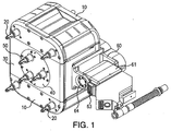
Figure 1 is an isometric drawing of an exemplary design of an automated positioner; -
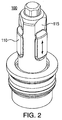
Figure 2 is an isometric view of a tube gripper head; -
Figure 3 is a cross-sectional drawing of an exemplary tube gripper inserted in a tube; and -
Figure 4 is an exploded view of an exemplary tube gripper. - An inspection and repair robot is disclosed. The design provides a very efficient footprint for moving and repositioning eddy current test probes within a steam generator. The unique motion and small size provide high flexibility in reaching all tubes within the tube sheet without complex repositioning motions. This provides quick and efficient motion in positioning the robot to a target zone or specific tube. All of this is accomplished at state of the art speed. In an exemplary embodiment, the robot can transverse across the tube sheet at speeds of up to 2,54 cm/s (5 feet per minute) for large moves and can achieve tube-to-tube speeds during test or repair operations of up to 10,2 cm/s (4 inches/second). The robot utilizes built-in machine vision for secondary tube verification for all attached tooling.
- With reference to
Figure 1 , an exemplary repair and inspection robot has anouter housing 10 comprising fourhousing grippers 20; a slidingbody center 30, comprising a rotatinggripper pod 40, which has threegrippers 50. Thesliding body center 30 also has atool head interface 60 comprising atool head lock 61 with a hot shoe (not shown),machine vision lighting 63 and integratedmachine vision camera 64. The tool head lock is rotatably attached to thetool head bracket 60. The robot moves across a tube sheet by alternately inserting and locking grippers into the tubes from either theouter housing 10 or the rotating gripper pod 40. It can be seen that when the three central grippers are inserted into tubes, the outer housing can rotate to any angle and translate a limited distance away from the rotating gripper pod via the sliding relationship between the center body and the outer housing. Once theouter housing 10 has repositioned itself with respect to the center body, thetube grippers 20 in theouter housing 10 are inserted into tubes and locked and thetube grippers 50 in the rotatingpod 40 are released and withdrawn from the tube sheet. The sliding body is then free to move with respect to the outer housing to engage new tubes. This process is repeated until the housing reaches the required location on the tube sheet. - The configuration of the four
outer housing grippers 20 and three rotating pod grippers is designed to support a broad range of square and tri-pitch tube sheet configuration, pitches and patterns. The body is designed to fit through the smallest man-way openings in existing equipment. The controller for the robot is also as small as possible to maximize platform space. A small diameter control cable minimizes cable tangle. - In an exemplary embodiment, there is a host computer, which is outside the tube sheet environment. There is also an external controller in the tube sheet environment that communicates with the host computer and with the robot.
- The host computer and software plans the robot movements and sends commands to the controller. It is typically remote to the radioactive environment where the robot and controller work. It sends commands through Ethernet to the controller which is external to the robot. The controller communicates to the robot via a power/data cable that carries the CAN communication and power for the devices. The robot has multiple CAN devices for the specific functions. It receives and executes commands directly from the controller.
- The controller has communication with both robot and host computer/software.
- Sequences for robot moves from one position to another are determined by the host computer and transmitted to the robot external controller.
- To make a move the external controller issues a command with arguments for the specific type of the device and an address for the device. For a motion axis, this may include commands for the motor on the axis in the form of rotation in degrees, rotation direction and rotation speed for an axis along with the address on the serial bus for the device.
- The host computer software manages the logic of how to move and issues commands to the controller which in turns formats them in to the instructions for the devices described above.
-
Figure 2 shows an exemplarytube gripper head 100. The gripper head has threegripping shoes 110 that slide along three channels equally spaced around the outside wall of the gripper head. Each channel has aninclined surface 115 that is in contact with the gripper shoe. Theinclined surface 115 forces thegripper shoe 110 away from the center of the gripper head when the shoes are pushed up into a tube, in a direction away from therobot body 10. As such, the grippers are self-locking. Once the shoes are forced up into a tube, a force created by air pressure is exerted forcing the gripper bodies away from the tube sheet, thus forcing the shoes against the tube wall. When the robot is below a tube sheet, the weight of the robot pulling down on the gripper head keeps the shoes locked against the tube wall, even if power is removed. When the tube sheet is not horizontal, reactionary force away from the tubes keeps the grippers locked. Any force tending to pull the robot away from the tubes will keep the grippers locked in place. The gripper shoes are withdrawn only by forcibly retracting the shoes while extending the gripper body slightly into the tube wall to aid in pushing theshoes 110 back down theinclined surface 115 and away from the tube wall. - In an embodiment, the friction between the
shoe 110 face and theinclined surface 115 is reduced by a friction reduction element (not shown). It is critical to the operation of the gripper shoes that the friction between the shoe and the inclined surface be controlled so that less force is required to move the shoe across the inclined plane than is required to move the shoe across the tube wall. In an embodiment, a plastic insert is inserted between theshoe 110 and theinclined surface 115. -
Figure 3 is a cross section view showing a gripper head inserted in atube wall 200. Agripper shoe 110 is shown pressed against the wall, being forced into the wall by theinclined surface 115 of the slot in the gripper head. In an exemplary design, eachgripper shoe 110 is in contact with apushrod 120. To lock the shoe against thetube wall 200, thepushrod 120 is urged upward by aplate 150. When theplate 150 is retracted,spring 130 loaded return pins 140 urge thepushrods 120 back down, thus releasing outward pressure on the gripper shoes 110. As stated earlier, to aid in releasing the gripper shoes 110 from thetube wall 200, the entire gripper head assembly is urged upward into the tube slightly, moving theinclined surface 115 up and releasing the outward pressure on the gripper shoes 110. - The embodiment shown is an advanced high performance gripper design that will not cause tube damage, yet provides high load capacity (of up to 300 lbs per gripper) and automatically provides grip force to match the load applied to the robot. All of this is accomplished while remaining fail-safe during power service interruptions.
- In an exemplary design, the robot tube grippers (
Figures 2-4 ) have the following features: self locking tube ID gripper concept where the load of the robot helps lock and hold the lock; simultaneous deployment ofgripper 110 andtoe 116 along with the locking retract step; multi-stage custom air cylinder deployment / release mechanism, telescoping cylinders; simultaneously deploying, but individually retractinggripper shoes 110; individually replaceable gripper shoes; coatings or other friction reduction elements to provide slip plane surface between the gripper mandrel and shoe surface; hall effect, optical other type of sensor in the gripper head senses deployment status and senses plugs in the tube; multistage pneumatic locking gripper; robot load increases lock to tube surface; smooth gripper shoes do not impose stress points on tube wall, will not damage steam generator tubing; integrated hall sensors detect deployment and retraction position; failsafe grip during power interruptions; gripper heads are designed for quick change; and distributed I/O and on-board servo and control. Automatically and individually adjusting each gripper for optimum positioning of gripper within the tube inside diameter for accommodation of variances in tubing diameters for gripping and un-gripping operations. - In an embodiment, the position of the gripper within the tube is adaptively adjusted to account for variations in tube diameter and opening tolerances. There is an optimal depth range at which the gripper should be inserted into the tube. If the gripper is inserted too far into the tube, it is difficult to extract, since extraction requires extending the gripper slightly farther into the tube than the position where it is anchored. Anchoring the gripper to close to the open end of the tube can possibly damage the tube in some situations. Thus, it is useful to be able to locate the gripper in a limited insertion range in the tube. One way to do this is to include a position sensor on the gripper. The position sensor can be a Hall effect sensor or optical sensor. The gripper is inserted in the tube and locked and its position is determined. If the gripper is not in the desired area, the gripper is released and re-inserted. Positioning the gripper is a function of two timing parameters: there is a gripper insertion duration and a time at which the gripper shoes are forced outward to grip the tube wall. The combination of these two times is adjusted to place the gripper at differing depths within the tube. Because of variations in tube diameter and shape, the timing parameters are not universal. For this reason, an adaptive approach as described here is used to place the gripper in the desired location by adjusting the insertion time and shoe actuation time each time the gripper is repositioned until the gripper is anchored at the desired location in the tube.
- In an exemplary embodiment, a serial network connects internal electronic modules of the robot. The serial network also connects any electronics attached to the tool head, the external controller and an installation robot. The serial network eliminates the need for custom wiring between these devices and reduces wire count, thus increasing reliability and reducing cost. The use of the serial network allows for expansion and improvements to existing hardware since additional modules can be added that communicate with the existing modules by simply tapping into the serial network. In an embodiment, the serial network is an electrical network and is implemented with the industry standard CAN bus. In an alternate embodiment, the serial network is a fiber optic network. The serial network also allows a single external controller to control multiple system elements within the robot system on the same bus. An additional serial network is provided in the form of a "1-Wire" memory chip to communicate and manage information stored in system components for use in controlling system level inventory, storing of data and configuration of software operations. The "1-Wire" network provides for insuring proper system operation parameters are respected to avoid undesirable operation.
- In an exemplary design, the robot tool head interface has the following features: quick make/break air coupling combined with electrical (power and signal) connection and proximity / Hall effect auto-lock feature.
- Software for an exemplary design includes: kinematics, multiple robot coordination, and collision detection / avoidance; software inspection planning & simulation; motion path planning algorithms to validate operation in bowl; trajectory planning algorithms to provide optimal path to target location; movement optimization algorithms to control movement around plugs and stays; and efficient inspection planning algorithms to optimize eddy current testing inspection and delivery of repair tooling.
- Some features and benefits of the present invention include:
- Small footprint of the robot provides ultimate maneuverability for efficient repositioning in all regions of the tube sheet while occupying less area thereby allowing the use of multiple robots per head.
- Light Weight. At less than 18,1 kg (40lbs) the robot is easily transportable and installable. In conjunction with the small footprint it requires less energy to grip into the tube sheet.
- Fail-safe revolutionary gripper design ensures that the robot will remain attached to the tube sheet through loss of all power, yet remains easily removable during emergency situations.
- Fast and strong with a tube-to-tube speed of up to 10,2 cm/s (4 inches/sec) and up to 133,6 kg (300lbs) load capacity per gripper. The robot is capable of performing both high speed inspections and supporting the load demands of repair tooling.
- A simplified system uses CAN-bus (Controller-area Network) control system architecture. The robot provides the smallest robot cable bundle in the industry with a diameter of less than 2,54 cm (1 inch).
- Intelligent software control manages the telemetry of all robots within a steam generator to avoid robot to robot collisions as well as probe collisions with robots operating in the opposite channel head.
- Seamless Interface with Zetec's MIZ®-80iD intelligent system capabilities for exchange information between hardware components and tooling.
- While the invention has been described in detail and with reference to specific examples thereof, it will be apparent to one skilled in the art that various changes and modifications can be made therein without departing from the scope of the invention as defined in the apppended claims.
Claims (13)
- An apparatus for automated inspection and testing of a tube sheet wherein the tube sheet has a plurality of tube openings arranged on a tube sheet plane, the apparatus comprising:a core assembly comprising:a sliding body portion (30) containing a rotating gripper pod (40) with three tube grippers (50);a tool head coupling (60) hingedly mounted to said core assembly; andouter housing actuators; and characaterized by:a housing portion (10) with left and right outer housings;each outer housing comprising one or more tube grippers (20);wherein said sliding body portion moves with respect to said housing portion (10);wherein said core assembly is arranged between said left and right outer housings, and wherein said core assembly, including said rotating gripper pod (40), and said left and right outer housings have top surfaces aligned on a common plane which, when the apparatus is in use, is parallel to said tube sheet plane, and wherein said tube grippers (50) emerge from said rotating gripper pod (40) and left and right outer housings, respectively, perpendicular to said common plane, andwherein said core assembly actuators move said left and right outer housings with respect to said core assembly such that said top surfaces remain in said common plane.
- The apparatus of Claim 1, wherein
said tool head coupling (60) is a part of one of said sliding body portion or said housing portion, or
said tool head coupling (60) supports a tool head comprising an eddy current test probe for insertion into a tube in the tube sheet, or
said tool head coupling (60) supports a tool head comprising tube repair equipment. - The apparatus of Claim 1, further comprising machine vision (63, 64).
- The apparatus of Claim 1, comprising four tube grippers (20) on said housing portion.
- The apparatus of Claim 1, wherein said tube gripper comprises
a pneumatic actuator;
gripper shoes (110); and
sensors for detecting deployment and retraction position. - The apparatus of Claim 5, wherein
the tube gripper shoes (110) are locked against the tube inner wall by reactionary force directed away from the tube; or
said tube gripper comprises spring-loaded retractors in communication with said gripper shoes; or
said gripper shoes (110) have a tube contacting surface and an inner surface and said tube gripper further comprises a gripper shoe mating surface, and a gripper shoe friction reducer wherein said gripper shoe friction reducer reduces the friction between said gripper shoe inner surface and said gripper shoe mating surface such that less force is required to slide said gripper shoe along said gripper shoe mating surface than is required to slide said gripper shoe tube contacting surface against said tube wall. - The apparatus of Claim 1, further comprising a plurality of electronic modules interconnected by a serial network.
- The apparatus of Claim 7, wherein said serial network also connects said apparatus to an external controller.
- The apparatus of Claim 1, wherein said tool head coupling (60) supports alternately an eddy current test probe and a tube repair device.
- The apparatus of Claim 1, wherein each of said tube grippers comprises
an actuator; and
gripper shoes (110);
wherein said gripper shoes (110) have a tube contacting surface and an inner surface and said tube gripper further comprises a gripper shoe mating surface, and a gripper shoe friction reducer wherein said gripper shoe friction reducer reduces the friction between said gripper shoe inner surface and said gripper shoe mating surface such that less force is required to slide said gripper show along said gripper shoe mating surface than is required to slide said gripper shoe tube contacting surface against said tube wall. - The apparatus of Claim 1, wherein when at least two of said rotating gripper pod (40) tube grippers (50) are locked into tubes and none of said outer housing tube grippers are inserted into tubes,
the rotating gripper pod (40) can be actuated to rotate the apparatus about an axis that is perpendicular to said tube sheet plane; or
the outer housing actuators can be actuated to move said outer housings across the tube sheet parallel to said tube sheet plane; or
said outer housing actuators can be actuated to move said core assembly across said tube sheet parallel to said tube sheet plane. - The apparatus of claim 8, wherein said serial network also connects an installer device to said external controller.
- The apparatus of Claim 5, further comprising
an insertion actuator, and
a gripper shoe actuator, said insertion actuator and said gripper shoe actuator being arranged for(a) activating said insertion actuator for a first time period during which the device is inserted into the tube;(b) activating said gripper shoe actuator for a second time period;(c) sensing the location of the device within the tube;(d) adjusting the position of the device within in the tube by retracting the device, and reinserting by repeating (a) and (b) the device with different values for at least one of said first and second time periods.
Priority Applications (2)
| Application Number | Priority Date | Filing Date | Title |
|---|---|---|---|
| SI201031325A SI2389538T1 (en) | 2009-01-19 | 2010-01-19 | Apparatus for automated positioning of eddy current test probe |
| EP16183475.9A EP3163161B1 (en) | 2009-01-19 | 2010-01-19 | Apparatus for automated positioning of eddy current test probe |
Applications Claiming Priority (2)
| Application Number | Priority Date | Filing Date | Title |
|---|---|---|---|
| US14562909P | 2009-01-19 | 2009-01-19 | |
| PCT/US2010/021407 WO2010083521A2 (en) | 2009-01-19 | 2010-01-19 | Apparatus for automated positioning of eddy current test probe |
Related Child Applications (1)
| Application Number | Title | Priority Date | Filing Date |
|---|---|---|---|
| EP16183475.9A Division EP3163161B1 (en) | 2009-01-19 | 2010-01-19 | Apparatus for automated positioning of eddy current test probe |
Publications (2)
| Publication Number | Publication Date |
|---|---|
| EP2389538A2 EP2389538A2 (en) | 2011-11-30 |
| EP2389538B1 true EP2389538B1 (en) | 2016-08-10 |
Family
ID=42336330
Family Applications (2)
| Application Number | Title | Priority Date | Filing Date |
|---|---|---|---|
| EP16183475.9A Active EP3163161B1 (en) | 2009-01-19 | 2010-01-19 | Apparatus for automated positioning of eddy current test probe |
| EP10700929.2A Active EP2389538B1 (en) | 2009-01-19 | 2010-01-19 | Apparatus for automated positioning of eddy current test probe |
Family Applications Before (1)
| Application Number | Title | Priority Date | Filing Date |
|---|---|---|---|
| EP16183475.9A Active EP3163161B1 (en) | 2009-01-19 | 2010-01-19 | Apparatus for automated positioning of eddy current test probe |
Country Status (9)
| Country | Link |
|---|---|
| US (3) | US8746089B2 (en) |
| EP (2) | EP3163161B1 (en) |
| JP (1) | JP5676479B2 (en) |
| KR (3) | KR101894596B1 (en) |
| CN (1) | CN102388266B (en) |
| CA (2) | CA2750221C (en) |
| ES (2) | ES2605227T3 (en) |
| SI (2) | SI3163161T1 (en) |
| WO (1) | WO2010083521A2 (en) |
Families Citing this family (18)
| Publication number | Priority date | Publication date | Assignee | Title |
|---|---|---|---|---|
| JP2012042185A (en) * | 2010-08-23 | 2012-03-01 | Mitsubishi Heavy Ind Ltd | Clamper, and in-water-chamber operation device |
| US8278779B2 (en) | 2011-02-07 | 2012-10-02 | General Electric Company | System and method for providing redundant power to a device |
| CN102649274A (en) * | 2011-02-25 | 2012-08-29 | 富泰华工业(深圳)有限公司 | Robot claw and robot adopting same |
| GB2522472B (en) * | 2014-01-27 | 2017-09-06 | Epsilon Optics Aerospace Ltd | A method and apparatus for a structural monitoring device adapted to be locatable within a tubular structure |
| CN104249368B (en) * | 2014-09-09 | 2016-06-01 | 上海交通大学 | Double columnar form Self-Reconfigurable Modular Robot |
| EP3224806B1 (en) * | 2014-11-24 | 2024-06-05 | Kitov Systems Ltd. | Automated inspection |
| US9961194B1 (en) | 2016-04-05 | 2018-05-01 | State Farm Mutual Automobile Insurance Company | Systems and methods for authenticating a caller at a call center |
| CN105945962B (en) * | 2016-05-19 | 2018-01-30 | 哈尔滨工业大学 | Articulated type climbing robot for the detection of steam generator heat pipe |
| DE102016013245A1 (en) | 2016-11-08 | 2018-06-07 | Westinghouse Electric Germany Gmbh | Drill for working pipes in radioactive environment |
| DE102016013247A1 (en) * | 2016-11-08 | 2018-05-09 | Westinghouse Electric Germany Gmbh | Drilling device for processing pipes on tube sheets in a radioactive environment |
| WO2018165488A2 (en) * | 2017-03-08 | 2018-09-13 | Fisher Benjamin D | Apparatus and method for baffle bolt repair |
| CN106970146B (en) * | 2017-03-28 | 2020-02-21 | 哈尔滨工业大学 | Positioning and connecting mechanism of steam generator heat-transfer pipe detection equipment |
| US11112382B2 (en) * | 2018-03-21 | 2021-09-07 | Infrastructure Preservation Corporation | Robotic magnetic flux inspection system for bridge wire rope suspender cables |
| US20220260529A1 (en) * | 2019-03-21 | 2022-08-18 | Infrastructure Preservation Corporation | Robotic magnetic flux inspection system for broadcast tower support cables |
| FR3095274B1 (en) * | 2019-04-19 | 2021-04-02 | Framatome Sa | Device for checking a weld of a hollow longitudinal tubular element |
| CN112066158A (en) * | 2019-12-10 | 2020-12-11 | 天目爱视(北京)科技有限公司 | Intelligent pipeline robot |
| CN111458404A (en) * | 2020-05-20 | 2020-07-28 | 四川纽赛特工业机器人制造有限公司 | Automatic change pipe fitting test center |
| CN112945507B (en) * | 2021-02-03 | 2023-05-19 | 中国空气动力研究与发展中心高速空气动力研究所 | Hypersonic wind tunnel axisymmetric spray pipe |
Family Cites Families (46)
| Publication number | Priority date | Publication date | Assignee | Title |
|---|---|---|---|---|
| US2865640A (en) * | 1955-12-21 | 1958-12-23 | Exxon Research Engineering Co | Tube holding apparatus |
| DE1627286C3 (en) * | 1967-09-14 | 1973-01-18 | Schmid & Wezel | Hand-held device with reciprocating tool |
| US3495546A (en) * | 1967-11-03 | 1970-02-17 | American Mach & Foundry | Speed control device for pipeline inspection apparatus |
| US3913752A (en) * | 1973-08-01 | 1975-10-21 | Combustion Eng | Remotely movable platform |
| US3889820A (en) * | 1973-08-01 | 1975-06-17 | Combustion Eng | Method and apparatus for suspendedly supporting a platform |
| JPS5157489A (en) * | 1974-11-15 | 1976-05-19 | Mitsubishi Heavy Ind Ltd | Jidokensasochino kontorooruhoho |
| FR2309314A1 (en) * | 1974-12-05 | 1976-11-26 | Framatome Sa | DEVICE FOR SELECTIVE POSITIONING OF AN ORGAN ON A TUBULAR PLATE |
| CA1014724A (en) | 1975-03-11 | 1977-08-02 | Peter D. Stevens-Guille | Locating test probes in heat exchanger tubes |
| US4018345A (en) * | 1975-11-18 | 1977-04-19 | Combustion Engineering, Inc. | Surface traversing apparatus |
| US4018346A (en) * | 1975-11-18 | 1977-04-19 | Combustion Engineering, Inc. | Mounting arrangement for anchor fingers on a surface traversing apparatus |
| US4074814A (en) * | 1976-03-26 | 1978-02-21 | Combustion Engineering, Inc. | Method and apparatus for controlling surface traversing device |
| US4193735A (en) * | 1978-04-24 | 1980-03-18 | Combustion Engineering, Inc. | Work table for a stepped platform |
| GB2039268B (en) * | 1978-12-15 | 1983-01-19 | Exxon Research Engineering Co | Metal extraction by solid-liquid agglomerates |
| FR2448143A1 (en) * | 1979-02-05 | 1980-08-29 | Intercontrole Sa | METHOD AND DEVICE FOR REMOVING A PROBE HOLDER FROM THE LOWER CHAMBER OF A VERTICAL TUBULAR HEAT EXCHANGER |
| FR2503920B1 (en) * | 1981-04-08 | 1987-08-21 | Intercontrole Sa | DEVICE FOR POSITIONING A MEMBER OPPOSING THE PERFORATIONS OF A PLATE |
| FR2503921A1 (en) | 1981-04-10 | 1982-10-15 | Commissariat Energie Atomique | DEVICE FOR POSITIONING A BODY INTO PERFORATIONS OF A PLATE AND METHOD FOR REMOTELY MOUNTING SUCH A DEVICE |
| FR2513927A1 (en) * | 1981-10-05 | 1983-04-08 | Framatome Sa | TELE-MANIPULATOR FOR INTERVENTION IN A STEAM GENERATOR WATER BOX |
| US4449599A (en) * | 1982-09-27 | 1984-05-22 | Combustion Engineering, Inc. | Finger walker for tube sheet |
| JPS5997864A (en) | 1982-11-29 | 1984-06-05 | 三菱重工業株式会社 | Intermittent shifter for work |
| US4688327A (en) * | 1983-10-03 | 1987-08-25 | Westinghouse Electric Corp. | Sleeving of tubes of steam generator |
| US4597294A (en) * | 1984-06-25 | 1986-07-01 | Westinghouse Electric Corp. | Ultrasonic nondestructive tubing inspection system |
| DE3509177C1 (en) * | 1985-03-14 | 1986-10-02 | Brown Boveri Reaktor GmbH, 6800 Mannheim | Device for introducing a cylindrical body, in particular a sleeve, into a tube of a steam generator |
| JPH086894B2 (en) | 1985-03-22 | 1996-01-29 | 株式会社日立製作所 | Heat exchanger Water chamber work Robot movement / holding device |
| US4702878A (en) * | 1986-01-15 | 1987-10-27 | Westinghouse Electric Corp. | Search and retrieval device |
| JPS6344162A (en) * | 1986-08-11 | 1988-02-25 | Kubota Ltd | Cracking detector for suction roll shell |
| US4720902A (en) * | 1986-12-22 | 1988-01-26 | Carrier Corporation | One step tension expander and method of using |
| US4829648A (en) * | 1987-01-27 | 1989-05-16 | Westinghouse Electric Corp. | Apparatus and method for simultaneously loading a reinforcing sleeve and mandrel into a tube |
| JPH073333B2 (en) * | 1988-01-28 | 1995-01-18 | 住友ゴム工業株式会社 | Method and device for detecting defective joint portion of elastic sheet |
| US4872524A (en) * | 1988-04-13 | 1989-10-10 | Oconnor Chadwell | Wheel-less walking dolly |
| FR2644568B1 (en) | 1989-03-16 | 1991-07-05 | Intercontrole Sa | INTERVENTION DEVICE, PARTICULARLY FOR CHECKING, INSPECTING AND MAINTAINING HEAT EXCHANGERS |
| FR2645328B1 (en) * | 1989-04-04 | 1991-07-19 | Framatome Sa | DEVICE FOR CENTERING AN INTERVENTION TOOL IN A STEAM GENERATOR TUBE |
| JPH0333651A (en) * | 1989-06-30 | 1991-02-13 | Chubu Electric Power Co Inc | Automatic inspection apparatus |
| US5355063A (en) * | 1990-11-01 | 1994-10-11 | Westinghouse Electric Corp. | Robotic system for servicing the heat exchanger tubes of a nuclear steam generator |
| FR2674938B1 (en) | 1991-04-05 | 1993-07-30 | Barras Provence | VEHICLE FOR EXPLORING AND MAINTAINING A TUBE NETWORK OF A STEAM GENERATOR. |
| US6672257B1 (en) * | 1994-05-06 | 2004-01-06 | Foster-Miller, Inc. | Upper bundle steam generator cleaning system and method |
| US5890553A (en) * | 1996-08-01 | 1999-04-06 | California Institute Of Technology | Multifunction automated crawling system |
| DE29700027U1 (en) | 1997-01-02 | 1998-04-30 | Siemens AG, 80333 München | Test manipulator for eddy current and ultrasonic testing of hollow cylindrical nuclear reactor components, in particular control rod drive housings |
| AUPO724797A0 (en) * | 1997-06-06 | 1997-07-03 | Down Hole Technologies Pty Ltd | Retrieval head for a drill bit composed of a plurality of bit segments |
| JPH11174032A (en) * | 1997-12-10 | 1999-07-02 | Toshiba Corp | Device and method for inspection of intermediate heat exchanger |
| TW463028B (en) * | 1998-04-21 | 2001-11-11 | Hitachi Shipbuilding Eng Co | Working robot for heat exchangers and operating method thereof |
| US6450104B1 (en) * | 2000-04-28 | 2002-09-17 | North Carolina State University | Modular observation crawler and sensing instrument and method for operating same |
| US7314343B2 (en) * | 2002-07-22 | 2008-01-01 | Westinghouse Electric Co. Llc | Miniature manipulator for servicing the interior of nuclear steam generator tubes |
| DK1877644T3 (en) * | 2005-05-03 | 2016-10-17 | Noetic Tech Inc | GRIP TOOL |
| JP2008089328A (en) | 2006-09-29 | 2008-04-17 | Hitachi Ltd | Eddy current flaw detector and eddy current flaw detection method |
| CA2646927C (en) * | 2007-12-10 | 2014-01-21 | Noetic Technologies Inc. | Gripping tool with driven screw grip activation |
| US8317455B2 (en) * | 2009-11-11 | 2012-11-27 | Peinemann Equipment B.V. | Device and method for removing a bundle from a heat exchanger |
-
2010
- 2010-01-14 US US12/687,261 patent/US8746089B2/en active Active
- 2010-01-19 KR KR1020117019217A patent/KR101894596B1/en active IP Right Grant
- 2010-01-19 SI SI201031881T patent/SI3163161T1/en unknown
- 2010-01-19 KR KR1020177009662A patent/KR102110018B1/en active IP Right Grant
- 2010-01-19 WO PCT/US2010/021407 patent/WO2010083521A2/en active Application Filing
- 2010-01-19 EP EP16183475.9A patent/EP3163161B1/en active Active
- 2010-01-19 CA CA2750221A patent/CA2750221C/en active Active
- 2010-01-19 EP EP10700929.2A patent/EP2389538B1/en active Active
- 2010-01-19 KR KR1020187024283A patent/KR102081528B1/en active IP Right Grant
- 2010-01-19 CA CA2967589A patent/CA2967589C/en active Active
- 2010-01-19 SI SI201031325A patent/SI2389538T1/en unknown
- 2010-01-19 CN CN201080011051.4A patent/CN102388266B/en active Active
- 2010-01-19 ES ES10700929.2T patent/ES2605227T3/en active Active
- 2010-01-19 ES ES16183475T patent/ES2728721T3/en active Active
- 2010-01-19 JP JP2011546426A patent/JP5676479B2/en active Active
-
2013
- 2013-08-09 US US13/963,630 patent/US9273985B2/en active Active
-
2016
- 2016-02-26 US US15/055,178 patent/US20160176685A1/en not_active Abandoned
Also Published As
| Publication number | Publication date |
|---|---|
| EP2389538A2 (en) | 2011-11-30 |
| KR20180098684A (en) | 2018-09-04 |
| CA2967589A1 (en) | 2010-07-22 |
| WO2010083521A3 (en) | 2011-09-29 |
| US9273985B2 (en) | 2016-03-01 |
| JP2012515895A (en) | 2012-07-12 |
| JP5676479B2 (en) | 2015-02-25 |
| KR102110018B1 (en) | 2020-05-13 |
| US8746089B2 (en) | 2014-06-10 |
| SI3163161T1 (en) | 2019-08-30 |
| KR101894596B1 (en) | 2018-10-04 |
| CN102388266A (en) | 2012-03-21 |
| WO2010083521A2 (en) | 2010-07-22 |
| EP3163161B1 (en) | 2019-03-13 |
| CA2967589C (en) | 2019-06-25 |
| EP3163161A2 (en) | 2017-05-03 |
| US20140033837A1 (en) | 2014-02-06 |
| ES2605227T3 (en) | 2017-03-13 |
| SI2389538T1 (en) | 2017-04-26 |
| US20160176685A1 (en) | 2016-06-23 |
| CA2750221C (en) | 2017-07-04 |
| KR102081528B1 (en) | 2020-02-25 |
| US20100181791A1 (en) | 2010-07-22 |
| ES2728721T3 (en) | 2019-10-28 |
| KR20170045358A (en) | 2017-04-26 |
| KR20110121687A (en) | 2011-11-08 |
| EP3163161A3 (en) | 2017-06-21 |
| CA2750221A1 (en) | 2010-07-22 |
| CN102388266B (en) | 2014-12-03 |
Similar Documents
| Publication | Publication Date | Title |
|---|---|---|
| EP2389538B1 (en) | Apparatus for automated positioning of eddy current test probe | |
| US9272423B2 (en) | Robotic tool interchange system | |
| EP2619079B1 (en) | Carrier vessel for supplying pipes to an underwater-pipeline laying vessel, and method for transferring pipes from a carrier vessel to an underwater-pipeline laying vessel | |
| EP1523395B1 (en) | Miniature manipulator for servicing the interior of nuclear steam generator tubes | |
| US10967465B2 (en) | Apparatus and method for baffle bolt repair | |
| KR20180032569A (en) | Automated mounting device for performing assembly jobs in an elevator shaft of an elevator system | |
| EP0979512A2 (en) | Inspection device | |
| CN109071181B (en) | Method and assembly device for carrying out an installation operation in an elevator shaft of an elevator installation | |
| CN108687559A (en) | Automatic tool head for drilling machine is placed and assembling equipment | |
| JPS62106294A (en) | Method and device for mounting heat-transfer tube sleeve of steam generator | |
| EP4252978A2 (en) | Articulated manipulator for navigating and servicing a heat exchanger | |
| JPH1039088A (en) | Fuel handling machine for reactor | |
| ITPI20120086A1 (en) | DEVICE FOR UNLOCKING A TOOL OF A MACHINE TOOL |
Legal Events
| Date | Code | Title | Description |
|---|---|---|---|
| PUAI | Public reference made under article 153(3) epc to a published international application that has entered the european phase |
Free format text: ORIGINAL CODE: 0009012 |
|
| AK | Designated contracting states |
Kind code of ref document: A2 Designated state(s): AT BE BG CH CY CZ DE DK EE ES FI FR GB GR HR HU IE IS IT LI LT LU LV MC MK MT NL NO PL PT RO SE SI SK SM TR |
|
| AX | Request for extension of the european patent |
Extension state: AL BA RS |
|
| 17P | Request for examination filed |
Effective date: 20120328 |
|
| RBV | Designated contracting states (corrected) |
Designated state(s): AT BE BG CH CY CZ DE DK EE ES FI FR GB GR HR HU IE IS IT LI LT LU LV MC MK MT NL NO PL PT RO SE SI SK SM TR |
|
| DAX | Request for extension of the european patent (deleted) | ||
| RAP1 | Party data changed (applicant data changed or rights of an application transferred) |
Owner name: BABCOCK & WILCOX NUCLEAR ENERGY, INC. |
|
| REG | Reference to a national code |
Ref country code: DE Ref legal event code: R079 Ref document number: 602010035320 Country of ref document: DE Free format text: PREVIOUS MAIN CLASS: F22B0037000000 Ipc: B66C0001540000 |
|
| RIC1 | Information provided on ipc code assigned before grant |
Ipc: B66C 1/54 20060101AFI20151130BHEP Ipc: G01D 11/30 20060101ALI20151130BHEP Ipc: F22B 37/00 20060101ALI20151130BHEP Ipc: G01N 27/90 20060101ALI20151130BHEP Ipc: G01M 5/00 20060101ALI20151130BHEP |
|
| GRAP | Despatch of communication of intention to grant a patent |
Free format text: ORIGINAL CODE: EPIDOSNIGR1 |
|
| INTG | Intention to grant announced |
Effective date: 20160119 |
|
| GRAS | Grant fee paid |
Free format text: ORIGINAL CODE: EPIDOSNIGR3 |
|
| GRAR | Information related to intention to grant a patent recorded |
Free format text: ORIGINAL CODE: EPIDOSNIGR71 |
|
| GRAA | (expected) grant |
Free format text: ORIGINAL CODE: 0009210 |
|
| AK | Designated contracting states |
Kind code of ref document: B1 Designated state(s): AT BE BG CH CY CZ DE DK EE ES FI FR GB GR HR HU IE IS IT LI LT LU LV MC MK MT NL NO PL PT RO SE SI SK SM TR |
|
| INTG | Intention to grant announced |
Effective date: 20160701 |
|
| REG | Reference to a national code |
Ref country code: GB Ref legal event code: FG4D |
|
| REG | Reference to a national code |
Ref country code: CH Ref legal event code: EP Ref country code: AT Ref legal event code: REF Ref document number: 818801 Country of ref document: AT Kind code of ref document: T Effective date: 20160815 |
|
| REG | Reference to a national code |
Ref country code: IE Ref legal event code: FG4D |
|
| REG | Reference to a national code |
Ref country code: DE Ref legal event code: R096 Ref document number: 602010035320 Country of ref document: DE |
|
| REG | Reference to a national code |
Ref country code: LT Ref legal event code: MG4D |
|
| REG | Reference to a national code |
Ref country code: NL Ref legal event code: MP Effective date: 20160810 |
|
| REG | Reference to a national code |
Ref country code: AT Ref legal event code: MK05 Ref document number: 818801 Country of ref document: AT Kind code of ref document: T Effective date: 20160810 |
|
| REG | Reference to a national code |
Ref country code: FR Ref legal event code: PLFP Year of fee payment: 8 |
|
| PG25 | Lapsed in a contracting state [announced via postgrant information from national office to epo] |
Ref country code: NO Free format text: LAPSE BECAUSE OF FAILURE TO SUBMIT A TRANSLATION OF THE DESCRIPTION OR TO PAY THE FEE WITHIN THE PRESCRIBED TIME-LIMIT Effective date: 20161110 Ref country code: LT Free format text: LAPSE BECAUSE OF FAILURE TO SUBMIT A TRANSLATION OF THE DESCRIPTION OR TO PAY THE FEE WITHIN THE PRESCRIBED TIME-LIMIT Effective date: 20160810 Ref country code: HR Free format text: LAPSE BECAUSE OF FAILURE TO SUBMIT A TRANSLATION OF THE DESCRIPTION OR TO PAY THE FEE WITHIN THE PRESCRIBED TIME-LIMIT Effective date: 20160810 Ref country code: NL Free format text: LAPSE BECAUSE OF FAILURE TO SUBMIT A TRANSLATION OF THE DESCRIPTION OR TO PAY THE FEE WITHIN THE PRESCRIBED TIME-LIMIT Effective date: 20160810 Ref country code: IS Free format text: LAPSE BECAUSE OF FAILURE TO SUBMIT A TRANSLATION OF THE DESCRIPTION OR TO PAY THE FEE WITHIN THE PRESCRIBED TIME-LIMIT Effective date: 20161210 Ref country code: IT Free format text: LAPSE BECAUSE OF FAILURE TO SUBMIT A TRANSLATION OF THE DESCRIPTION OR TO PAY THE FEE WITHIN THE PRESCRIBED TIME-LIMIT Effective date: 20160810 |
|
| PG25 | Lapsed in a contracting state [announced via postgrant information from national office to epo] |
Ref country code: PT Free format text: LAPSE BECAUSE OF FAILURE TO SUBMIT A TRANSLATION OF THE DESCRIPTION OR TO PAY THE FEE WITHIN THE PRESCRIBED TIME-LIMIT Effective date: 20161212 Ref country code: LV Free format text: LAPSE BECAUSE OF FAILURE TO SUBMIT A TRANSLATION OF THE DESCRIPTION OR TO PAY THE FEE WITHIN THE PRESCRIBED TIME-LIMIT Effective date: 20160810 Ref country code: GR Free format text: LAPSE BECAUSE OF FAILURE TO SUBMIT A TRANSLATION OF THE DESCRIPTION OR TO PAY THE FEE WITHIN THE PRESCRIBED TIME-LIMIT Effective date: 20161111 Ref country code: SE Free format text: LAPSE BECAUSE OF FAILURE TO SUBMIT A TRANSLATION OF THE DESCRIPTION OR TO PAY THE FEE WITHIN THE PRESCRIBED TIME-LIMIT Effective date: 20160810 Ref country code: AT Free format text: LAPSE BECAUSE OF FAILURE TO SUBMIT A TRANSLATION OF THE DESCRIPTION OR TO PAY THE FEE WITHIN THE PRESCRIBED TIME-LIMIT Effective date: 20160810 Ref country code: PL Free format text: LAPSE BECAUSE OF FAILURE TO SUBMIT A TRANSLATION OF THE DESCRIPTION OR TO PAY THE FEE WITHIN THE PRESCRIBED TIME-LIMIT Effective date: 20160810 |
|
| REG | Reference to a national code |
Ref country code: ES Ref legal event code: FG2A Ref document number: 2605227 Country of ref document: ES Kind code of ref document: T3 Effective date: 20170313 |
|
| RAP2 | Party data changed (patent owner data changed or rights of a patent transferred) |
Owner name: BWXT NUCLEAR ENERGY, INC. |
|
| PG25 | Lapsed in a contracting state [announced via postgrant information from national office to epo] |
Ref country code: EE Free format text: LAPSE BECAUSE OF FAILURE TO SUBMIT A TRANSLATION OF THE DESCRIPTION OR TO PAY THE FEE WITHIN THE PRESCRIBED TIME-LIMIT Effective date: 20160810 Ref country code: RO Free format text: LAPSE BECAUSE OF FAILURE TO SUBMIT A TRANSLATION OF THE DESCRIPTION OR TO PAY THE FEE WITHIN THE PRESCRIBED TIME-LIMIT Effective date: 20160810 |
|
| REG | Reference to a national code |
Ref country code: DE Ref legal event code: R082 Ref document number: 602010035320 Country of ref document: DE Representative=s name: D YOUNG & CO LLP, GB Ref country code: DE Ref legal event code: R081 Ref document number: 602010035320 Country of ref document: DE Owner name: BWXT NUCLEAR ENERGY, INC., LYNCHBURG, US Free format text: FORMER OWNER: BABCOCK & WILCOX NUCLEAR ENERGY, INC., LYNCHBURG, VA., US Ref country code: DE Ref legal event code: R082 Ref document number: 602010035320 Country of ref document: DE Representative=s name: D YOUNG & CO LLP, DE |
|
| REG | Reference to a national code |
Ref country code: DE Ref legal event code: R097 Ref document number: 602010035320 Country of ref document: DE |
|
| PG25 | Lapsed in a contracting state [announced via postgrant information from national office to epo] |
Ref country code: CZ Free format text: LAPSE BECAUSE OF FAILURE TO SUBMIT A TRANSLATION OF THE DESCRIPTION OR TO PAY THE FEE WITHIN THE PRESCRIBED TIME-LIMIT Effective date: 20160810 Ref country code: DK Free format text: LAPSE BECAUSE OF FAILURE TO SUBMIT A TRANSLATION OF THE DESCRIPTION OR TO PAY THE FEE WITHIN THE PRESCRIBED TIME-LIMIT Effective date: 20160810 Ref country code: SM Free format text: LAPSE BECAUSE OF FAILURE TO SUBMIT A TRANSLATION OF THE DESCRIPTION OR TO PAY THE FEE WITHIN THE PRESCRIBED TIME-LIMIT Effective date: 20160810 Ref country code: BG Free format text: LAPSE BECAUSE OF FAILURE TO SUBMIT A TRANSLATION OF THE DESCRIPTION OR TO PAY THE FEE WITHIN THE PRESCRIBED TIME-LIMIT Effective date: 20161110 |
|
| PLBE | No opposition filed within time limit |
Free format text: ORIGINAL CODE: 0009261 |
|
| STAA | Information on the status of an ep patent application or granted ep patent |
Free format text: STATUS: NO OPPOSITION FILED WITHIN TIME LIMIT |
|
| REG | Reference to a national code |
Ref country code: SK Ref legal event code: T3 Ref document number: E 23152 Country of ref document: SK |
|
| 26N | No opposition filed |
Effective date: 20170511 |
|
| PG25 | Lapsed in a contracting state [announced via postgrant information from national office to epo] |
Ref country code: MC Free format text: LAPSE BECAUSE OF FAILURE TO SUBMIT A TRANSLATION OF THE DESCRIPTION OR TO PAY THE FEE WITHIN THE PRESCRIBED TIME-LIMIT Effective date: 20160810 |
|
| REG | Reference to a national code |
Ref country code: IE Ref legal event code: MM4A |
|
| PG25 | Lapsed in a contracting state [announced via postgrant information from national office to epo] |
Ref country code: LU Free format text: LAPSE BECAUSE OF NON-PAYMENT OF DUE FEES Effective date: 20170119 |
|
| REG | Reference to a national code |
Ref country code: FR Ref legal event code: PLFP Year of fee payment: 9 |
|
| PG25 | Lapsed in a contracting state [announced via postgrant information from national office to epo] |
Ref country code: IE Free format text: LAPSE BECAUSE OF NON-PAYMENT OF DUE FEES Effective date: 20170119 |
|
| PG25 | Lapsed in a contracting state [announced via postgrant information from national office to epo] |
Ref country code: MT Free format text: LAPSE BECAUSE OF NON-PAYMENT OF DUE FEES Effective date: 20170119 |
|
| REG | Reference to a national code |
Ref country code: SI Ref legal event code: SP73 Owner name: BWXT NUCLEAR ENERGY, INC.; US Effective date: 20180906 |
|
| PG25 | Lapsed in a contracting state [announced via postgrant information from national office to epo] |
Ref country code: HU Free format text: LAPSE BECAUSE OF FAILURE TO SUBMIT A TRANSLATION OF THE DESCRIPTION OR TO PAY THE FEE WITHIN THE PRESCRIBED TIME-LIMIT; INVALID AB INITIO Effective date: 20100119 |
|
| PG25 | Lapsed in a contracting state [announced via postgrant information from national office to epo] |
Ref country code: CY Free format text: LAPSE BECAUSE OF NON-PAYMENT OF DUE FEES Effective date: 20160810 |
|
| PG25 | Lapsed in a contracting state [announced via postgrant information from national office to epo] |
Ref country code: MK Free format text: LAPSE BECAUSE OF FAILURE TO SUBMIT A TRANSLATION OF THE DESCRIPTION OR TO PAY THE FEE WITHIN THE PRESCRIBED TIME-LIMIT Effective date: 20160810 |
|
| PG25 | Lapsed in a contracting state [announced via postgrant information from national office to epo] |
Ref country code: TR Free format text: LAPSE BECAUSE OF FAILURE TO SUBMIT A TRANSLATION OF THE DESCRIPTION OR TO PAY THE FEE WITHIN THE PRESCRIBED TIME-LIMIT Effective date: 20160810 |
|
| REG | Reference to a national code |
Ref country code: DE Ref legal event code: R082 Ref document number: 602010035320 Country of ref document: DE Representative=s name: D YOUNG & CO LLP, DE |
|
| P01 | Opt-out of the competence of the unified patent court (upc) registered |
Effective date: 20230606 |
|
| PGFP | Annual fee paid to national office [announced via postgrant information from national office to epo] |
Ref country code: SK Payment date: 20231220 Year of fee payment: 15 |
|
| PGFP | Annual fee paid to national office [announced via postgrant information from national office to epo] |
Ref country code: FI Payment date: 20231222 Year of fee payment: 15 |
|
| PGFP | Annual fee paid to national office [announced via postgrant information from national office to epo] |
Ref country code: ES Payment date: 20240207 Year of fee payment: 15 |
|
| PGFP | Annual fee paid to national office [announced via postgrant information from national office to epo] |
Ref country code: DE Payment date: 20240115 Year of fee payment: 15 Ref country code: GB Payment date: 20240119 Year of fee payment: 15 Ref country code: CH Payment date: 20240202 Year of fee payment: 15 |
|
| PGFP | Annual fee paid to national office [announced via postgrant information from national office to epo] |
Ref country code: SI Payment date: 20231221 Year of fee payment: 15 |
|
| PGFP | Annual fee paid to national office [announced via postgrant information from national office to epo] |
Ref country code: FR Payment date: 20240124 Year of fee payment: 15 Ref country code: BE Payment date: 20240116 Year of fee payment: 15 |