KR20180098682A - Clip cartridge - Google Patents
Clip cartridge Download PDFInfo
- Publication number
- KR20180098682A KR20180098682A KR1020187024219A KR20187024219A KR20180098682A KR 20180098682 A KR20180098682 A KR 20180098682A KR 1020187024219 A KR1020187024219 A KR 1020187024219A KR 20187024219 A KR20187024219 A KR 20187024219A KR 20180098682 A KR20180098682 A KR 20180098682A
- Authority
- KR
- South Korea
- Prior art keywords
- clip
- sleeve
- inner case
- ring
- distal end
- Prior art date
- Legal status (The legal status is an assumption and is not a legal conclusion. Google has not performed a legal analysis and makes no representation as to the accuracy of the status listed.)
- Granted
Links
Images


Classifications
-
- A—HUMAN NECESSITIES
- A61—MEDICAL OR VETERINARY SCIENCE; HYGIENE
- A61B—DIAGNOSIS; SURGERY; IDENTIFICATION
- A61B17/00—Surgical instruments, devices or methods
- A61B17/12—Surgical instruments, devices or methods for ligaturing or otherwise compressing tubular parts of the body, e.g. blood vessels or umbilical cord
- A61B17/122—Clamps or clips, e.g. for the umbilical cord
- A61B17/1222—Packages or dispensers therefor
-
- A—HUMAN NECESSITIES
- A61—MEDICAL OR VETERINARY SCIENCE; HYGIENE
- A61B—DIAGNOSIS; SURGERY; IDENTIFICATION
- A61B17/00—Surgical instruments, devices or methods
- A61B17/12—Surgical instruments, devices or methods for ligaturing or otherwise compressing tubular parts of the body, e.g. blood vessels or umbilical cord
- A61B17/122—Clamps or clips, e.g. for the umbilical cord
-
- A—HUMAN NECESSITIES
- A61—MEDICAL OR VETERINARY SCIENCE; HYGIENE
- A61B—DIAGNOSIS; SURGERY; IDENTIFICATION
- A61B17/00—Surgical instruments, devices or methods
- A61B17/12—Surgical instruments, devices or methods for ligaturing or otherwise compressing tubular parts of the body, e.g. blood vessels or umbilical cord
- A61B17/128—Surgical instruments, devices or methods for ligaturing or otherwise compressing tubular parts of the body, e.g. blood vessels or umbilical cord for applying or removing clamps or clips
- A61B17/1285—Surgical instruments, devices or methods for ligaturing or otherwise compressing tubular parts of the body, e.g. blood vessels or umbilical cord for applying or removing clamps or clips for minimally invasive surgery
-
- A—HUMAN NECESSITIES
- A61—MEDICAL OR VETERINARY SCIENCE; HYGIENE
- A61B—DIAGNOSIS; SURGERY; IDENTIFICATION
- A61B17/00—Surgical instruments, devices or methods
- A61B2017/00526—Methods of manufacturing
- A61B2017/0053—Loading magazines or sutures into applying tools
-
- A—HUMAN NECESSITIES
- A61—MEDICAL OR VETERINARY SCIENCE; HYGIENE
- A61B—DIAGNOSIS; SURGERY; IDENTIFICATION
- A61B17/00—Surgical instruments, devices or methods
- A61B17/12—Surgical instruments, devices or methods for ligaturing or otherwise compressing tubular parts of the body, e.g. blood vessels or umbilical cord
- A61B2017/12004—Surgical instruments, devices or methods for ligaturing or otherwise compressing tubular parts of the body, e.g. blood vessels or umbilical cord for haemostasis, for prevention of bleeding
Landscapes
- Health & Medical Sciences (AREA)
- Surgery (AREA)
- Life Sciences & Earth Sciences (AREA)
- Heart & Thoracic Surgery (AREA)
- Nuclear Medicine, Radiotherapy & Molecular Imaging (AREA)
- Vascular Medicine (AREA)
- Engineering & Computer Science (AREA)
- Biomedical Technology (AREA)
- Reproductive Health (AREA)
- Medical Informatics (AREA)
- Molecular Biology (AREA)
- Animal Behavior & Ethology (AREA)
- General Health & Medical Sciences (AREA)
- Public Health (AREA)
- Veterinary Medicine (AREA)
- Surgical Instruments (AREA)
Abstract
본 발명은, 일련의 수기를 용이하게 행하는 것이 가능한 구조의 클립을, 용이하고 또한 확실히 처치구 본체에 장착하는 것이 가능한 클립 카트리지를 제공한다. 본 발명의 클립 카트리지(200)는, 클립(110)을 수용하는 제1 수용 영역(32)을 갖는 내부 케이스(30)와, 처치구 본체(90)가 삽통되는 장척의 삽통 구멍(43)과 내부 케이스(30)를 이동 가능하게 수용하는 제2 수용 영역(42)을 갖는 외부 케이스(40)를 구비한다. 삽통 구멍(43)에 처치구 본체(90)가 삽입되어 조작 와이어가 전방으로 밀어넣어짐으로써, 선단 연결부와 슬리브의 확경부가 시스로부터 돌출되어 제2 수용 영역(42)에 들어감과 함께 확경부가 확경되고, 조작 와이어가 더 밀어넣어짐으로써 선단 연결부와 클립(110)이 연결 상태가 되어, 조작 와이어가 견인됨으로써, 내부 케이스(30)가 외부 케이스(40)에 대하여 후퇴하여 슬리브를 후방으로 압압함으로써, 확경부가 축경하면서 시스로 끌어들여진다.The present invention provides a clip cartridge capable of easily and surely mounting a clip having a structure capable of easily performing a series of handwriting on the treatment instrument body. The clip cartridge 200 of the present invention includes an inner case 30 having a first receiving area 32 for receiving the clip 110, a long insertion hole 43 for inserting the treatment instrument body 90, And an outer case (40) having a second receiving area (42) for movably receiving the inner case (30). The treatment tool main body 90 is inserted into the insertion hole 43 and the operation wire is pushed forward so that the distal end connecting portion and the enlarged diameter portion of the sleeve protrude from the sheath into the second receiving area 42, The distal end connecting portion and the clip 110 are connected and the operating wire is pulled so that the inner case 30 is retracted relative to the outer case 40 to move the sleeve backward By depressing, the enlarged diameter portion is drawn into the sheath with a reduced diameter.
Description
본 발명은, 클립 카트리지에 관한 것이다.The present invention relates to a clip cartridge.
내시경하에서 체강 내의 생체 조직을 절제하고, 그 절제 부위를 결찰하여 지혈하는 내시경용 클립 장치가 제공되고 있다. 이 종류의 내시경용 클립 장치에 관하여, 특허문헌 1에는, 처치구 본체에 마련된 조작 와이어의 선단의 화살촉 훅을, 클립의 기단부의 연결 부재에 삽입하여 연결함으로써, 클립이 처치구 본체에 연결된 상태로 하기 위한 클립 카트리지(동일 문헌의 케이스)에 대하여 기재되어 있다.There is provided an endoscopic clip device for cutting a biotissue in a body cavity under an endoscope and ligating the cut-off site for hemostasis. With respect to this kind of endoscope clip apparatus, in Patent Document 1, an arrowhead hook at the tip of an operating wire provided in a treatment instrument body is inserted into and connected to a connecting member at a base end portion of a clip, The clip cartridge (case of the same document) is described.
특허문헌 1의 내시경용 클립 장치를 이용하여 생체 조직을 결찰하기 위해서는, 화살촉 훅을 연결 부재에 삽입한 상태로 조작 와이어의 견인 조작을 행한다. 생체 조직이 결찰된 상태로부터 추가로 조작 와이어를 강하게 견인하면, 연결 부재의 세경부가 파단되고, 클립은 생체 조직을 결찰한 상태로 체강 내에 유치(留置)된다.In order to ligate the living tissue using the endoscope clip apparatus of Patent Document 1, the pulling operation of the operating wire is performed in a state in which the arrowhead hook is inserted into the connecting member. When the operation wire is further pulled from the ligature tissue, the diameter of the connecting member is broken, and the clip is retained in the body cavity in a ligated state.
파단된 연결 부재는, 화살촉 훅에 연결된 상태로 회수된 후, 화살촉 훅으로부터 분리되어 폐기된다.The broken connecting member is recovered in a state of being connected to the arrowhead hook, and then is separated from the arrowhead hook and discarded.
상술한 바와 같이, 특허문헌 1의 내시경용 클립 장치에 있어서는, 클립을 체강 내에 유치한 후에, 파단된 연결 부재를 회수하고, 화살촉 훅으로부터 분리하여 폐기할 필요가 있다. 이로 인하여, 일련의 수기(手技)가 번잡하고, 감염 등의 문제가 발생할 우려가 있다.As described above, in the endoscope clip apparatus of Patent Document 1, after the clip is held in the body cavity, the broken connecting member must be collected, separated from the arrowhead hook, and discarded. As a result, a series of hand techniques are troublesome and a problem such as infection may occur.
본 발명은 상술한 바와 같은 과제를 감안하여 이루어진 것이며, 일련의 수기를 용이하게 행하는 것이 가능한 구조의 클립을, 용이하고 또한 확실히 처치구 본체에 장착하는 것이 가능한 클립 카트리지를 제공하는 것이다.SUMMARY OF THE INVENTION The present invention has been made in view of the above-mentioned problems, and it is an object of the present invention to provide a clip cartridge which can easily and surely be mounted on a treatment tool body with a structure capable of easily carrying out a series of handwriting.
본 발명은, 장척의 처치구 본체에 대하여 클립을 연결하기 위하여 이용되는 클립 카트리지로서,The present invention is a clip cartridge used for connecting a clip to a long treatment instrument body,
상기 클립은, 생체 조직을 파지하기 위한 복수의 완부(腕部) 및 상기 완부의 기단 측에 마련된 계지부(係止部)를 갖는 클립 본체를 구비하고,The clip includes a clip body having a plurality of arm portions for gripping a living tissue and an engagement portion provided at a base end side of the arm portion,
상기 처치구 본체는, 장척의 시스와, 상기 시스의 내부에 진퇴 이동 가능하게 삽통되어 원위단(遠位端)에 선단 연결부가 마련된 조작 와이어와, 상기 시스의 내부에 수납 가능하며 상기 선단 연결부를 수용하는 통형의 슬리브와, 상기 조작 와이어로부터 상기 슬리브에 전진력 및 후퇴력을 전달하는 전달부를 가지며,Wherein the treatment instrument body comprises an elongated sheath, an operation wire inserted into the sheath so as to be retreated and retractably moved and provided with a distal end connection portion at a distal end thereof, and an operation wire accommodated in the sheath, And a transmission portion for transmitting a forward force and a retraction force from the operating wire to the sleeve,
상기 슬리브는, 탄성적으로 자기 확개(擴開) 가능한 확경부와, 상기 확경부보다 근위 측에 마련되고 상기 확경부보다 직경 방향의 강성이 높은 통형의 슬리브 본체를 갖고,Wherein the sleeve has a large diameter portion capable of being elastically self-expanding and a cylindrical sleeve body provided on a proximal side of the diameter-increased portion and having a higher rigidity in the radial direction than the enlarged diameter portion,
상기 클립 카트리지는,The clip cartridge includes:
상기 클립을 수용하는 제1 수용 영역을 갖는 내부 케이스와,An inner case having a first receiving area for receiving the clip,
상기 처치구 본체가 삽통되는 장척의 삽통 구멍과, 상기 삽통 구멍의 선단에 연통하고 있음과 함께 상기 내부 케이스를 선단 측 및 기단 측으로 이동 가능하게 수용하는 제2 수용 영역을 갖는 외부 케이스를 구비하며,And an outer case having a long insertion hole into which the treatment instrument main body is inserted and a second accommodation area communicating with the distal end of the insertion hole and accommodating the inner case movably to the distal end side and the proximal end side,
상기 삽통 구멍에 상기 처치구 본체가 삽입된 상태로, 상기 조작 와이어가 전방으로 밀어넣어짐으로써, 상기 선단 연결부와 상기 슬리브의 상기 확경부가, 상기 시스로부터 선단 측으로 돌출되어 상기 제2 수용 영역에 있어서의 상기 내부 케이스와 상기 삽통 구멍의 사이의 영역으로 들어감과 함께, 상기 확경부가 탄성적으로 확경되고,The manipulating wire is pushed forward in a state in which the treatment tool body is inserted into the insertion hole so that the distal end connecting portion and the enlarged diameter portion of the sleeve protrude from the sheath toward the distal end side, And the enlarged diameter portion is resiliently enlarged, and at the same time,
상기 조작 와이어가 더 전방으로 밀어넣어짐으로써, 상기 선단 연결부가 상기 슬리브에 대하여 상대적으로 전진함으로써 상기 슬리브로부터 선단 측으로 돌출하고, 상기 선단 연결부와 상기 계지부가 연결된 연결 상태가 되며,The distal end connecting portion is advanced relative to the sleeve so as to protrude from the sleeve toward the distal end side so that the distal end connecting portion and the engaging portion are connected to each other,
상기 연결 상태에서 상기 조작 와이어가 기단 측으로 견인됨으로써, 상기 내부 케이스가 상기 제2 수용 영역 내에서 상기 외부 케이스에 대하여 상대적으로 후퇴하고, 상기 내부 케이스가 상기 슬리브를 후방으로 압압함으로써 상기 확경부가 축경하면서 상기 시스로 끌어들여지는 클립 카트리지를 제공하는 것이다.The operating wire is pulled toward the proximal end side in the connected state so that the inner case retracts relative to the outer case in the second receiving area and the inner case pushes the sleeve backward, And the clip cartridge is pulled into the sheath.
본 발명에 의하면, 일련의 수기를 용이하게 행하는 것이 가능한 구조의 클립을, 용이하고 또한 확실히 처치구 본체에 장착하는 것이 가능해진다.According to the present invention, it is possible to easily and surely mount a clip having a structure capable of easily performing a series of handwriting on the treatment instrument main body.
도 1은 실시형태에 관한 클립 카트리지의 분해 사시도이다.
도 2는 클립 카트리지의 내부 케이스를 구성하는 내부 케이스 구성 부품의 사시도이다.
도 3은 개완(開腕) 상태의 클립의 평면도이다.
도 4는 클립 카트리지에 클립을 수용한 상태를 나타내는 평면도이다.
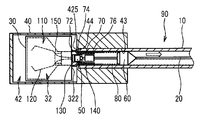
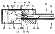
도 5는 도 4의 A-A선을 따른 측단면도이다.
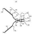
도 6은 내시경용 클립 장치의 일례를 나타내는 사시도이다.
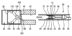
도 7a는 내시경용 클립 장치의 처치구 본체에 클립을 장착하는 일련의 동작 중, 장착 전 상태를 설명하기 위한 모식도이다.
도 7b는 내시경용 클립 장치의 처치구 본체에 클립을 장착하는 일련의 동작 중, 장착한 상태를 설명하기 위한 모식도이다.
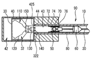
도 8a는 내시경용 클립 장치의 처치구 본체에 클립을 장착하는 일련의 동작을 설명하기 위한 모식도이다.
도 8b는 내시경용 클립 장치의 처치구 본체에 클립을 장착하는 일련의 동작을 설명하기 위한 모식도이다.
도 8c는 내시경용 클립 장치의 처치구 본체에 클립을 장착하는 일련의 동작을 설명하기 위한 모식도이다.
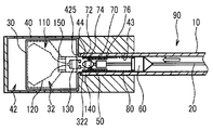
도 9a는 내시경용 클립 장치의 처치구 본체에 클립을 장착하는 일련의 동작을 설명하기 위한 모식도이다.
도 9b는 내시경용 클립 장치의 처치구 본체에 클립을 장착하는 일련의 동작을 설명하기 위한 모식도이다.
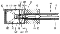
도 10a는 내시경용 클립 장치의 처치구 본체에 클립을 장착하는 일련의 동작을 설명하기 위한 모식도이다.
도 10b는 내시경용 클립 장치의 처치구 본체에 클립을 장착하는 일련의 동작을 설명하기 위한 모식도이다.
도 10c는 내시경용 클립 장치의 처치구 본체에 클립을 장착하는 일련의 동작을 설명하기 위한 모식도이다.
도 11a는 폐완(閉腕) 상태의 클립을 나타내는 평면도이다.
도 11b는 폐완 상태의 클립을 나타내는 측면도이다.1 is an exploded perspective view of a clip cartridge according to the embodiment.
2 is a perspective view of an inner case component constituting an inner case of the clip cartridge.
3 is a plan view of a clip in an open arm state.
4 is a plan view showing a state in which a clip is accommodated in the clip cartridge.
5 is a side sectional view along the line AA in Fig.
6 is a perspective view showing an example of an endoscope clip device.
Fig. 7A is a schematic view for explaining a state before mounting a clip in the instrument body of the endoscope clip device in a series of operations. Fig.
Fig. 7B is a schematic diagram for explaining a state in which a clip is attached to a treatment instrument body of the endoscope clip device during a series of operations. Fig.
8A is a schematic view for explaining a series of operations for attaching a clip to a treatment instrument main body of an endoscope clip device.
Fig. 8B is a schematic diagram for explaining a series of operations for attaching a clip to a treatment instrument main body of an endoscope clip device. Fig.
8C is a schematic diagram for explaining a series of operations for mounting a clip on a treatment instrument main body of an endoscope clip device;
9A is a schematic view for explaining a series of operations for mounting a clip on a treatment instrument main body of an endoscope clip device.
Fig. 9B is a schematic view for explaining a series of operations for attaching a clip to a treatment instrument main body of an endoscope clip device. Fig.
10A is a schematic diagram for explaining a series of operations for mounting a clip on a treatment instrument main body of an endoscope clip device.
Fig. 10B is a schematic view for explaining a series of operations for attaching a clip to a treatment instrument main body of an endoscope clip device. Fig.
Fig. 10C is a schematic view for explaining a series of operations for attaching a clip to a treatment instrument main body of an endoscope clip device. Fig.
11A is a plan view showing a clip in a closed arm state.
11B is a side view showing a clip in a closed state.
이하, 본 발명의 실시형태에 대하여, 도면을 이용하여 설명한다. 또한, 모든 도면에 있어서, 동일한 구성 요소에는 동일한 부호를 붙이고, 중복되는 설명은 적절하게 생략한다.BEST MODE FOR CARRYING OUT THE INVENTION Hereinafter, embodiments of the present invention will be described with reference to the drawings. In all the drawings, the same constituent elements are denoted by the same reference numerals and redundant explanations are appropriately omitted.
도 1은 실시형태에 관한 클립 카트리지(200)의 분해 사시도이다. 도 2는 클립 카트리지(200)의 내부 케이스(30)(도 1)를 구성하는 내부 케이스 구성 부품(31)의 사시도이다. 도 3은 개완 상태의 클립(110)의 평면도이다.1 is an exploded perspective view of a
도 4는 클립 카트리지(200)에 클립(110)을 수용한 상태를 나타내는 평면도이다. 또한, 도 4에 있어서는, 외부 케이스(40)를 구성하는 한 쌍의 외부 케이스 구성 부품(41) 중 상측의 외부 케이스 구성 부품(41)의 도시를 생략하고 있음과 함께, 내부 케이스(30)를 구성하고 있는 한 쌍의 내부 케이스 구성 부품(31) 중 상측의 내부 케이스 구성 부품(31)에 대해서는, 그 측벽(315)(후술) 및 인접벽(316)(후술)만을 나타내고 있다. 도 5는 도 4의 A-A선을 따른 측단면도이다. 도 6은 내시경용 클립 장치(이하, 클립 장치로 약기하는 경우가 있음)(100)의 일례를 나타내는 사시도이다.4 is a plan view showing a state in which the
도 7a, 도 7b부터 도 10a, 도 10b, 도 10c의 각 도는, 내시경용 클립 장치(100)의 처치구 본체(90)에 클립(110)을 장착하는 일련의 동작을 설명하기 위한 모식도이다.Figs. 7A, 7B, 10A, 10B, and 10C are schematic diagrams for explaining a series of operations for attaching the
도 11a는 폐완 상태의 클립(110)을 나타내는 평면도이며, 도 11b는 측면도이다.11A is a plan view showing a
또한, 본 명세서에 있어서 "축 방향"이란, 특별히 설명이 없는 한, 처치구 본체(90)의 조작 와이어(20)(도 7a, 도 7b 등 참조)의 진퇴 방향을 의미한다. 또, "단면"이란, 특별히 설명이 없는 한, 내시경용 클립 장치(100)를 축 방향으로 절단한 종단면을 의미한다.In this specification, the term "axial direction" means a direction in which the operation wire 20 (refer to FIG. 7A, FIG. 7B, etc.) of the
또, "원위 측(또는 원위)"이란, 특별히 설명이 없는 한, 내시경용 클립 장치(100), 이에 장착된 클립(110) 또는 클립 카트리지(200)에 있어서, 내시경용 클립 장치(100)의 조작자로부터 먼 측을 호칭하고, 구체적으로는 클립(110)의 완부(120)의 선단(클로부(126))이 있는 측을 말한다. 또, "근위 측(또는 근위)"이란, 특별히 설명이 없는 한, 내시경용 클립 장치(100), 클립(110) 또는 클립 카트리지(200)에 있어서 조작자에게 가까운 측을 말한다. 또, 내시경용 클립 장치(100), 클립(110) 또는 클립 카트리지(200)의 구성 요소가 원위 측으로 이동하는 것을 전진한다고 하고, 반대로 근위 측으로 이동하는 것을 후퇴한다고 하는 경우가 있다. 또한 "선단 측(또는 선단)"을 "원위 측(또는 원위)"과 동의로 이용하고, "기단 측(또는 기단)"을 "근위 측(또는 근위)"과 동의로 이용한다.The term "distal side (or distal side)" means an
또, 기단 측으로부터 선단 측, 또는, 선단 측으로부터 기단 측을 향하는 방향을, 선기단 방향 또는 전후 방향이라고 칭한다.The direction from the proximal end side to the distal end side or from the distal end side to the proximal end side is referred to as a line base end direction or a forward / backward direction.
또, 후술하는 바와 같이 클립 카트리지(200)는 편평하게 형성되어 있다. 그리고, 선기단 방향과 클립 카트리지(200)의 두께 방향의 쌍방에 대하여 직교하는 방향을 폭 방향이라고 칭한다.In addition, as will be described later, the
본 실시형태에 관한 클립 카트리지(200)는, 장척의 처치구 본체(90)에 대하여 클립(110)을 연결하기 위하여 이용되는 클립 카트리지(200)이다.The
도 3에 나타내는 바와 같이, 클립(110)은, 생체 조직을 파지하기 위한 복수의 완부(120)와, 완부(120)의 기단 측에 마련된 계지부(130)를 갖는 클립 본체(110a)를 구비하고 있다.3, the
도 6부터 도 10a, 도 10b, 도 10c 중 어느 하나에 나타나는 바와 같이, 처치구 본체(90)는, 장척의 시스(10)와, 시스(10)의 내부에 진퇴 이동 가능하게 삽통되어 원위단에 선단 연결부(50)가 마련된 조작 와이어(20)와, 시스(10)의 내부에 수납 가능하며 선단 연결부(50)를 수용하는 통형의 슬리브(축경 슬리브(70))와, 조작 와이어(20)로부터 슬리브에 전진력 및 후퇴력을 전달하는 전달부(예를 들면, 신축부(80))를 갖는다.6 to 10, 10, 10, and 10c, the
슬리브는, 탄성적으로 자기 확개 가능한 확경부(72)와, 확경부(72)보다 근위 측에 마련되고 확경부(72)보다 직경 방향의 강성이 높은 통형의 슬리브 본체(76)를 갖는다. 여기에서, 슬리브 본체(76)의 직경 방향의 강성이, 확경부(72)의 직경 방향의 강성보다 높은이란, 슬리브 본체(76) 및 확경부(72)에 대하여 각각 직경 방향 내측에 힘이 가해졌을 때에, 탄성 변형에 의한 직경 방향 내측으로의 변위량이, 확경부(72)보다 슬리브 본체(76) 쪽이 작아지는 것을 의미한다.The sleeve has a resiliently self-expanding
도 1, 도 4, 도 5, 도 7a, 도 7b~도 10a, 도 10b, 도 10c 중 어느 하나에 나타나는 바와 같이, 클립 카트리지(200)는, 내부 케이스(30)와 외부 케이스(40)를 구비하고 있다. 이 중 내부 케이스(30)는, 클립(110)을 수용하는 제1 수용 영역(32)을 갖고 있다. 또, 외부 케이스(40)는, 처치구 본체(90)가 삽통되는 장척의 삽통 구멍(43)과, 삽통 구멍(43)의 선단에 연통하고 있음과 함께 내부 케이스(30)를 선단 측 및 기단 측으로 이동 가능하게 수용하는 제2 수용 영역(42)을 갖는다.The
도 7a, 도 7b, 도 8a, 도 8b에 나타나는 바와 같이, 삽통 구멍(43)에 처치구 본체(90)가 삽입된 상태로, 조작 와이어(20)가 전방으로 밀어넣어짐으로써, 선단 연결부(50)와 슬리브의 확경부(72)가, 시스(10)로부터 선단 측으로 돌출되어 제2 수용 영역(42)에 있어서의 내부 케이스(30)와 삽통 구멍(43)의 사이의 영역으로 들어감과 함께, 확경부(72)가 탄성적으로 확경한다.The
도 8c에 나타나는 바와 같이, 조작 와이어(20)가 더 전방으로 밀어넣어짐으로써, 선단 연결부(50)가 슬리브에 대하여 상대적으로 전진함으로써 슬리브로부터 선단 측으로 돌출하고, 선단 연결부(50)와 계지부(130)가 연결된 연결 상태가 된다.8C, the
도 9a, 도 9b부터 도 10a에 나타나는 바와 같이, 연결 상태에서 조작 와이어(20)가 기단 측으로 견인됨으로써, 내부 케이스(30)가 제2 수용 영역(42) 내에서 외부 케이스(40)에 대하여 상대적으로 후퇴하고, 내부 케이스(30)가 슬리브를 후방으로 압압함으로써 확경부(72)가 축경하면서 시스(10)로 끌어들여진다.The
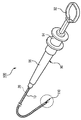
클립 장치(100)가 구비하는 처치구 본체(90)의 구체적인 구조는 특별히 한정되지 않는다. 도 6에는, 손가락 걸이 링(92), 슬라이더(94) 및 본체 축(96)을 구비하는 처치구 본체(90)를 예시한다. 클립 장치(100)의 사용자는, 예를 들면, 손가락 걸이 링(92)에 손가락(예를 들면 엄지)을 걸고, 슬라이더(94)를 다른 손가락(예를 들면 검지 및 중지)으로 협지한 상태로, 본체 축(96)에 대하여 슬라이더(94)를 상대 이동시켜 조작한다. 이로써, 슬라이더(94)에 연결된 조작 와이어(20)가 시스(10)의 내부에서 진퇴 이동한다. 또, 처치구 본체(90)의 전체를 축 둘레로 회전시킴으로써, 슬라이더(94)와 함께 조작 와이어(20)가 회전한다. 시스(10)가 내시경의 겸자 구멍의 벽면에 밀착하고 있는 경우, 조작 와이어(20)는 시스(10)의 내부에서 축 회전하게 된다. 이하, 처치구 본체(90)나 조작 와이어(20), 클립(110)이 축 회전하는 것을 "토크 회전"한다고 하는 경우가 있다.The specific structure of the
클립 장치(100)는, 조작 와이어(20)의 선단에 클립(110)을 연결한 상태로, 내시경의 겸자 구멍(도시 생략)에 삽통하여 이용된다. 구체적으로는, 클립 장치(100)는, 체강 내에 유치된 내시경의 겸자 구멍에 대하여 근위 측으로부터 시스(10)를 삽입하고, 겸자 구멍의 원위 개구로부터 시스(10)의 원위단을 돌출시켜, 추가로 시스(10)로부터 클립(110)을 노출시켜 생체 조직을 결찰하는 데에 이용할 수 있다. 결찰되는 생체 조직으로서는, 내시경적 점막 하층 박리 방법(ESD)의 피처치 부위 등의 점막벽 외에, 혈관 등의 체관을 들 수 있다.The
클립(110)은, 생체 조직을 결찰하는 것이며, 완부(120)로 생체 조직을 결찰함으로써, 예를 들면 지혈 처치, 봉축(縫縮) 및 마킹 등의 처치를 행할 수 있다. 완부(120)는 자기 확개력을 갖고, 후술하는 바와 같이 폐완 상태의 완부(120)를 시스(10)로부터 돌출시킴으로써 완부(120)는 자연스럽게 확개하여 개완 상태가 된다. 여기에서, "자기 확개"란, 닫으려고 하는 외력에 대하여 반발하여 스스로 열려고 하는 것을 말한다.The
클립(110)은, 복수의 완부(120)와 계지부(130)를 갖는 클립 본체(110a) 외에, 복수의 완부(120)가 모아져 삽입된 체결 링(150)을 구비하고 있다. 체결 링(150)이 완부(120)에 대하여 상대적으로 완부(120)의 선단 측으로 이동함으로써, 복수의 완부(120)의 선단(클로부(126))이 서로 닫힌 상태가 되도록 구성되어 있다.The
보다 상세하게는, 클립(110)은, 서로 대향하는 한 쌍의 완부(120)를 구비하고 있다.More specifically, the
한 쌍의 완부(120)는, 계지부(130)로부터 원위 측(도 3에 있어서의 좌측)을 향하여 돌출되는 기단부(122)와, 이 기단부(122)의 원위 측에 연접되어 있는 완 본체부(124)를 각각 구비하고 있다. 기단부(122)는 원위 측을 향하여 외향으로 만곡하고 있다.The pair of
여기에서, "외향"이란, 조작 와이어(20)의 축 또는 당해 축의 연장선으로부터 멀어지는 방향을 의미하며, 예를 들면 직경 방향의 외측 방향이다. "내향"이란, 조작 와이어(20)의 축 또는 당해 축의 연장선에 가까워지는 방향을 의미하고, 예를 들면 직경 방향의 내측 방향이다.Here, the "outward direction " means a direction away from the axis of the
완 본체부(124)는 직선형으로 형성되어 있으며, 완 본체부(124)의 선단에는 클로부(126)가 형성되어 있다. 완 본체부(124) 및 클로부(126)는 생체 조직을 주로 파지하는 파지 영역이다. 클로부(126)는, 한 쌍의 완 본체부(124)로부터 내향으로 돌출되어 있고, 생체 조직에 파고들어감으로써 클립(110)의 파지력을 향상시킨다.The
완부(120)는, 기단부(122)와 완 본체부(124)의 경계에서 굴곡하고 있고, 또 이러한 경계에는 완부(120)의 폭 치수가 국소적으로 축소하는 세폭부(細幅部)(123)가 형성되어 있다(도 11b 참조).The width of the
도 3에 나타내는 바와 같이, 계지부(130)와 한 쌍의 완부(120)는 일체 성형되어 클립 본체(110a)를 구성하고 있다. 즉 한쪽의 클로부(126), 완 본체부(124) 및 기단부(122)와, 다른 쪽의 클로부(126), 완 본체부(124) 및 기단부(122)가 계지부(130)를 통하여 심리스로 연속 형성되어 있다.As shown in Fig. 3, the
보다 구체적으로는, 금속제의 판재를 뚫어, 프레스 및 굽힘 가공함으로써, 서로 일체적인 한 쌍의 완부(120) 및 계지부(130)를 포함하는 클립 본체(110a)를 제작할 수 있다. 이러한 금속 재료로서는, 스테인리스강, 타이타늄 또는 타이타늄 합금 등을 예시할 수 있지만, 이에 한정되지 않는다. 또 상기 금속 재료는, 내부식성 피복 처리가 이루어진 것이어도 된다.More specifically, a clip
완 본체부(124)에는, 폭 방향의 중앙의 일부를 프레스(엠보스) 가공함으로써 보강부(125)가 형성되어 있다(도 11b 참조). 보강부(125)를 형성함으로써 완 본체부(124)의 두께 치수가 증대하고(도 3, 도 11a 참조), 완 본체부(124)의 굽힘 강성이 향상된다. 이로써, 생체 조직에 대한 높은 파지력을 얻을 수 있다. 보강부(125)는, 완 본체부(124) 중 클로부(126)를 제외한 선단부로부터, 세폭부(123)에 이르는 기단부까지 연속 형성되어 있다.A reinforcing
클립(110)의 체결 링(150)은 완부(120)에 대하여 진퇴 가능하게 장착되어 있다. 체결 링(150)을 완부(120)에 대하여 상대적으로 원위 측으로 이동시킴으로써, 개완 상태(도 3 참조)의 완부(120)를 자기 확개력에 저항하여 체결 링(150)으로 체결할 수 있다. 이로써, 완부(120)는 폐완 상태(도 11a 및 도 11b 참조)가 된다. 또, 체결 링(150)을 완부(120)에 대하여 상대적으로 후퇴시킴으로써 완부(120)는 자기 확개력에 의하여 개완한다. 또한, 환형의 체결 링(150)은, 둘레 방향에 걸쳐 둘레면 전체가 연속되는 전체 환형이어도 되고, 또는 둘레 방향의 일부에 절결이나 슬릿이 마련되어 있는 부분 환형이어도 된다.The fastening ring (150) of the clip (110) is movably mounted on the arm (120). By moving the
완부(120)의 완 본체부(124)는, 기단부(122)나 세폭부(123)보다 태폭(太幅)으로 형성되어 있어, 체결 링(150)이 세폭부(123)를 타고 넘어 완 본체부(124)까지 전진하는 것이 규제되어 있다. 또, 기단부(122)에는, 부분적으로 태폭으로 형성된 태폭부(121)가 형성되어 있다. 체결 링(150)의 근위 측의 내경은 태폭부(121)의 폭 치수보다 작다. 이로 인하여, 체결 링(150)이 태폭부(121)를 타고 넘어 클립(110)의 근위 측으로 이동하는 것도 규제되어 있다. 체결 링(150)은 태폭부(121)와 완 본체부(124)의 사이의 길이 영역에서 완부(120)에 대하여 진퇴 이동한다. 그리고, 체결 링(150)이 세폭부(123)에 감합(嵌合)함으로써 체결 링(150)은 완부(120)에 계지되고, 클립(110)은 폐완 상태로 고정된다.The
클립(110)의 계지부(130)는, 조작 와이어(20)의 선단의 선단 연결부(50)(도 7a 등)를 수용하는 공간(132)을 내부에 갖는 수용부(134)와, 이 수용부(134)의 기단 측에 내향으로 돌출 형성된 돌기부(140)를 갖고 있다. 수용부(134)가 공간(132) 내에 선단 연결부(50)를 수용함으로써, 클립(110)과 조작 와이어(20)는 서로 연결된다.The engaging
돌기부(140)는, 선단 연결부(50)에 의하여 확대되도록 탄성적 변형되어 개방되고, 또 탄성 복원됨으로써 선단 연결부(50)와 계합하여 이를 지지하는 클로부이다.The projecting
돌기부(140)는 수용부(134)의 근위 측에 배치되어 공간(132)의 일부 또는 전부를 개방 가능하게 폐쇄하는 부위이다. 돌기부(140)의 형상, 위치 및 크기는 특별히 한정되지 않는다. 예를 들면, 수용부(134)를 환형으로 형성하고, 돌기부(140)를 환형의 수용부(134)의 둘레면으로부터 직경 방향의 내향으로 돌출 형성해도 된다. 또는, 하기와 같이 수용부(134)를 환형 등의 기부(136)와, 이 기부(136)로부터 근위 측으로 돌출되는 돌편부(142)로 구성하고, 돌기부(140)를 당해 돌편부(142)의 선단에 형성해도 된다.The protruding
계지부(130)는, 완부(120)의 기단에 접속된 기부(136)와, 이 기부(136)로부터 기단 측으로 돌출 형성되어 수용부(134)를 구성하는 복수의 돌편부(142)를 구비하고 있다. 돌기부(140)는, 돌편부(142)의 근위 측의 선단부에 각각 형성되어 있다.The
기부(136)와 돌편부(142)와 돌기부(140)로 둘러싸이는 공간(132)에 조작 와이어(20)의 선단 연결부(50)는 수용된다. 기부(136)의 내경은 선단 연결부(50)의 최대 외경보다 작아, 기부(136)는 선단 연결부(50)의 전진 이동을 규제한다. 돌기부(140)는, 공간(132)에 수용된 선단 연결부(50)가 후퇴하는 것을 규제한다. 공간(132)에 수용된 선단 연결부(50)는, 기부(136)와 돌기부(140)로 선기단 방향으로 구속되어 공간(132)의 내부에서 진퇴 이동이 규제되어도 되고, 또는 공간(132)의 내부에서 선단 연결부(50)는 약간 축 방향으로 진퇴 이동 가능해도 된다.The distal
여기에서, 본 실시형태의 경우, 선단 연결부(50)는 괴상의 것이다. 선단 연결부(50)가 "괴상"이라는 것은, 선단 연결부(50)가 계지부(130)보다 두꺼우며, 선단 연결부(50)가 계지부(130)에 연결되고, 또 선단 연결부(50)가 계지부(130)로부터 발거(拔去)됨에 있어서, 계지부(130)의 변형에 비하여 선단 연결부(50)의 변형이 충분히 작은 것을 말한다. 괴상의 선단 연결부(50)의 구체적인 형상은 특별히 한정되지 않고, 도 7a에 나타내는 바와 같이 원위 측부와 근위단부가 각각 원위단과 근위단을 향하여 축경하는 형상인 것 외에, 기둥형이나 구형이어도 된다.Here, in the case of the present embodiment, the tip
예를 들면, 선단 연결부(50)의 단면 형상은 다각형이며, 바람직하게는 정다각형 단면이다. 일례로서 선단 연결부(50)는 정육각형 단면을 갖고 있다.For example, the cross-sectional shape of the tip
계지부(130)에는 복수의 돌편부(142)가 대향하여 배치되어 있다. 돌편부(142)의 수는 한정되지 않지만, 다각형 단면의 선단 연결부(50)의 외주 평면의 수보다 적은 수인 것이 바람직하다. 구체적으로는, 계지부(130)는, 예를 들면 2개의 돌편부(142)를 갖고 있다. 돌편부(142)는 선단 연결부(50)의 직경보다 세폭의 판형을 이루고 있다.A plurality of protruded
2개의 돌편부(142)는, 선단 연결부(50)의 외주 평면에 각각 대면 가능한 위치에 마련되어 있다. 보다 구체적으로는, 2개의 돌편부(142)는 계지부(130)의 기부(136)에 있어서 180도 대향하는 위치에 마련되어 있다.The two protruded
단, 본 발명은 이 예에 한정되지 않고, 3개의 돌편부(142)가 120도 간격으로 균등하게 대향 배치되어 있어도 된다. 돌편부(142)끼리의 대향 간격은, 선단 연결부(50)의 외주 평면에 돌편부(142)가 각각 밀착 또는 근접하는 것이 가능한 치수로 설정되어 있다.However, the present invention is not limited to this example, and three
선단 연결부(50)를 클립(110)(클립 본체(110a))에 연결하면, 수용부(134)에 수용된 선단 연결부(50)의 외주 평면을 둘러싸도록 하여, 복수의 돌편부(142)는 선단 연결부(50)에 밀착 또는 근접하여 배치된다. 이로써, 선단 연결부(50)를 토크 회전시키면 선단 연결부(50)의 외주 평면은 돌편부(142)를 축 둘레로 회전시켜, 계지부(130)를 통하여 클립 본체(110a) 전체에 토크를 부여한다.The distal
돌편부(142)의 근위 측의 선단에 형성된 돌기부(140)는, 기부(136)와 동심의 원주 상에 배치되어 있고, 부분 원호형으로 형성되어 있다. 개개의 돌기부(140)는, 중심각이 약 120도인 부분 원호형을 이루고, 2개의 돌기부(140)에 의하여 상기 원주의 약 3분의 2의 영역을 지지할 수 있도록 형성되어 있다.The
기부(136)는, 금속 재료 등의 판재를 굽힘 형성하고 단부 가장자리(138)를 서로 맞닿게 하여 이루어지는 환형을 이루고 있다. 복수의 돌편부(142)는, 환형의 기부(136)의 주위에 이간 배치되어 있다.The
도 3 및 도 11a에 나타내는 바와 같이, 맞닿은 단부 가장자리(138)의 맞댐 부분은, 인접하는 돌편부(142)끼리의 중간 위치에 배치되어 있다.As shown in Figs. 3 and 11A, the butted portion of the
환형의 기부(136)의 구체적인 형상은 특별히 한정되지 않고, 원통형, 각통형, 또는 이들의 조합 등을 예시할 수 있다. 또, 기부(136)는, 단부 가장자리(138)의 맞댐 부분이 서로 접촉한 전체 환형 외에, 단부 가장자리(138)의 맞댐 부분이 소정의 간격으로 이간된 부분 환형이어도 된다.The specific shape of the
기부(136)의 기단 측의 둘레 가장자리에는, 원위 측을 향하여 파인 복수의 오목부(137)가 형성되어 있다. 돌편부(142)는, 오목부(137)의 바닥부(139)로부터 기단 측으로 돌출 형성되어 있다. 이로써, 축 방향에 있어서의 계지부(130)의 치수를 억제하면서, 돌편부(142)를 길게 형성할 수 있고, 수용부(134)에 조작 와이어(20)의 선단 연결부(50)를 감합 또는 발거할 때에 돌편부(142)를 유연하게 변형시킬 수 있다.A plurality of concave portions 137 are formed on the peripheral edge of the base end side of the
다음으로, 도 6 및 도 7a 등에 나타내는 바와 같이, 처치구 본체(90)의 시스(10)는, 장척이며 가요성의 관형 부재이다. 시스(10)는, 클립 장치(100)와 함께 이용되는 내시경의 겸자 구멍보다 길다. 시스(10)는, 예를 들면 금속 와이어를 장척으로 권회한 코일층(도시 생략)으로 구성할 수 있다. 코일층의 내주면에는, 불소계 폴리머로 제작된 내층(도시 생략)이 마련되어 있어도 된다. 또, 시스(10)를 수지제의 와이어를 권회한 코일층으로 해도 되고, 가요성의 수지 튜브로 해도 된다.Next, as shown in Figs. 6 and 7A and the like, the
시스(10)의 내경 치수는, 조작 와이어(20)의 선단에 마련된 센터링부(60)(도 7a 등)를 슬라이딩 가능하게 수용하는 크기이다. 시스(10)는, 폐완 상태의 클립(110)을 내부에 수용 가능하다(도 10b, 도 10c 참조). 구체적으로는, 시스(10)의 내경은, 예를 들면, 100μm 이상 또한 2400μm 이하이다. 또, 시스(10)의 두께 치수는, 예를 들면, 100μm 이상 또한 350μm 이하이다. 이로써, 시스(10)의 굴곡성을 양호하게 할 수 있다.The inner diameter dimension of the
조작 와이어(20)는, 시스(10)에 삽통되어 있으며, 당해 시스(10)의 내부를 축 방향으로 진퇴 가능하게 되어 있다. 조작 와이어(20)는, 예를 들면, 스테인리스강, 내부식성 피복된 강철선, 타이타늄 또는 타이타늄 합금 등의 강성이 강한 금속 재료에 의하여 형성되어 있다. 금속판을 구성하는 금속 재료로서는, 스테인리스강, 타이타늄 또는 타이타늄 합금 등을 예시할 수 있지만, 이에 한정되지 않는다. 또 상기 금속 부재는, 적절히 내부식성 피복 처리가 이루어진 것이어도 된다. 조작 와이어(20)의 외주면에는, 불소계 폴리머로 제작된 외층(도시 생략)이 마련되어 있어도 된다.The
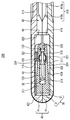
조작 와이어(20)의 원위단부에는, 예를 들면, 센터링부(60), 지주부(56), 선단 연결부(50), 신축부(80) 및 축경 슬리브(70)가 마련되어 있다.A centering
센터링부(60)는, 조작 와이어(20)보다 대경인 괴상를 이루고, 조작 와이어(20)의 원위단부에 고정되어 있다. 센터링부(60)는 원기둥형의 부위(원기둥부)를 포함하고, 이러한 원기둥부의 외경은 시스(10)의 내경과 동등하거나 약간 작게 형성되어 있다. 시스(10)의 내부에서 조작 와이어(20)를 진퇴 이동시킴에 따라 센터링부(60)는 시스(10)의 내부를 슬라이딩하여 진퇴한다. 이때, 센터링부(60)의 외경이 시스(10)의 내경과 대략 동일한 직경이면, 조작 와이어(20)는 시스(10)의 축심 근방에 위치한 채 진퇴 이동한다. 만곡한 내시경(도시 생략)의 겸자 구멍에 시스(10)가 삽입된 경우에도, 조작 와이어(20)는 당해 겸자 구멍의 중심선 상에 대략 위치하기 때문에 조작 와이어(20)의 경로 길이는 변화하지 않아, 선단 연결부(50)나 클립(110)이 시스(10)로부터 예측할 수 없게 돌출되어 버리는 것이 억제된다.The centering
조작 와이어(20)의 원위단부이며 센터링부(60)보다 원위 측의 위치에는, 조작 와이어(20)와 동일 축에 지주부(56)가 형성되어 있다. 지주부(56)의 원위단에는 선단 연결부(50)가 일체 형성되어 있다. 지주부(56)와 선단 연결부(50)의 사이에는, 잘록부(51)가 형성되어 있다(도 7a 등 참조). 신축부(80)는 지주부(56)를 수용하도록 하여 지주부(56)의 주위에 마련되고, 선단 연결부(50)는 축경 슬리브(70)의 내부에 수용 가능하게 되어 있다.A supporting
선단 연결부(50)의 원위부에 제2 경사면(54)이 마련되어 있다. 이로써, 선단 연결부(50)를 돌기부(140)에 대하여 기단 측으로부터 압압함으로써, 제2 경사면(54)은 돌기부(140)를 외향으로 탄성 변형시킨다.And a second
또, 선단 연결부(50)의 근위부에 제1 경사면(52)이 마련되어 있다. 이로써, 선단 연결부(50)가 수용부(134)에 수용된 상태로 조작 와이어(20)를 진퇴 방향의 근위 측으로 견인함으로써, 제1 경사면(52)은 돌기부(140)를 외향으로 변형시킨다.In addition, a first
제1 경사면(52) 및 제2 경사면(54)의 한쪽 또는 양쪽 모두는, 평면이어도 되고, 또는 곡면이어도 된다. 곡면인 경우는, 돌기부(140)를 적합하게 외향으로 확대시킬 수 있도록, 직경 방향의 외향으로 팽출하는 볼록면이어도 된다.Either or both of the first
제1 경사면(52) 또는 제2 경사면(54) 중 적어도 한쪽은, 원뿔대 또는 각뿔대 등의 뿔면형을 이루고 있다.At least one of the first
보다 구체적으로는, 제1 경사면(52)은 근위 측을 향하여 축경하는 원뿔대면이며, 제2 경사면(54)은 원위 측을 향하여 축경하는 원뿔대면이다.More specifically, the first
조작 와이어(20)의 원위단부에는, 시스(10)의 내부에 수납 가능하고, 또한 선단 연결부(50)를 수용하는 통형의 슬리브(축경 슬리브(70))가 마련되어 있다. 축경 슬리브(70)의 적어도 일부의 내경은, 선단 연결부(50)를 수용부(134)로부터 뽑아내는 것이 가능해질 때의 계지부(130)의 외경보다 작다.A distal end of the
축경 슬리브(70)는, 시스(10)에 대한 체결 링(150)의 후퇴 이동을 규제하고, 개완 상태의 클립(110)(도 3 참조)을 폐완 상태(도 11a 및 도 11b 참조)에 전이시키기 위한 부재이다. 축경 슬리브(70)는, 도 7a 등에 나타내는 바와 같이 시스(10)의 내부에 수납 가능하고, 또 조작 와이어(20)를 전진시킴으로써 축경 슬리브(70)의 일부(확경부(72))를 시스(10)로부터 돌출시키는 것이 가능하다(도 8b 등 참조).The
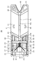
슬리브(축경 슬리브(70))는, 확경부(72), 축경 단차부(74) 및 슬리브 본체(76)를 갖고 있다. 확경부(72)는, 축경 슬리브(70)에 있어서의 원위 측에 마련되고 탄성적으로 자기 확개 가능하다. 축경 단차부(74)는, 확경부(72)의 근위 측에 마련되어 있다. 슬리브 본체(76)는, 축경 단차부(74)보다 더 근위 측에 마련되고, 확경부(72)보다 직경 방향의 강성이 높다.The sleeve (shaft sleeve 70) has a diameter enlarged
슬리브 본체(76)의 내경은, 도 9b에 나타내는 바와 같이, 선단 연결부(50)를 수용부(134)로부터 뽑아내는 것이 가능해질 때의 계지부(130)의 외경보다 작다. 이로 인하여, 계지부(130)와 선단 연결부(50)가 연결되어 있는 상태이며, 또한 돌기부(140) 및 돌편부(142)가 슬리브 본체(76)에 수용되어 있는 상태에서는, 돌편부(142)의 외향 변형을 슬리브 본체(76)가 구속하기 때문에, 선단 연결부(50)가 수용부(134)로부터 이탈하는 것이 방지된다.The inner diameter of the sleeve
단, 돌기부(140) 및 돌편부(142) 중 적어도 일부를 슬리브 본체(76)보다 후퇴시킴으로써, 돌편부(142)가 충분히 변형되어 선단 연결부(50)를 수용부(134)로부터 뽑아내는 것이 가능해진다.However, by retracting at least some of the protruding
축경 단차부(74)는, 슬리브 본체(76)와 확경부(72)의 사이에 있어서, 근위 측을 향하여 축경하는 테이퍼형으로 형성되어 있다. 축경 슬리브(70)의 구성 재료는, 외력에 의하여 축경 가능한 부재이면 특정의 재질에 한정되지 않는다. 예를 들면 금속 재료나, 수지, 고무 등의 엘라스토머를 이용할 수 있다.The shaft-shaft stepped
축경 슬리브(70)는 스테인리스강 등의 금속 재료로 제작된 통형체(파이프)이며, 확경부(72)의 원위단으로부터 근위 측을 향하여 절결 형성된 하나 이상의 슬릿(도시 생략)을 갖고 있다. 슬릿은, 축경 단차부(74)에 이르는 길이로 형성되어 있어도 된다. 이러한 슬릿을 가짐으로써, 축경 슬리브(70)의 적어도 확경부(72)는 확경 변형 또는 축경 변형되는 것이 가능하게 구성되어 있다. 확경부(72)는, 도 7a 등에 나타내는 바와 같이 축경 슬리브(70)가 시스(10)에 수용되고 또한 시스(10)에 구속되어 있는 상태일 때에, 시스(10)에 구속되어 있지 않은 자연 상태(도 8b 등)일 때보다 축경 변형되어, 외경이 시스(10)의 내경보다 소경으로 되어 있다.The
그리고, 도 8b 등에 나타내는 바와 같이 축경 슬리브(70)의 확경부(72)가 시스(10)로부터 원위 측으로 돌출됨으로써 확경부(72)는 자연 상태로 탄성 복원된다. 확경부(72)는, 자연 상태에서 시스(10)의 내경보다 대경이다. 또, 슬리브 본체(76)는 자연 상태에서 시스(10)의 내경보다 소경이며, 축경 단차부(74)는 자연 상태에서 시스(10)의 내경보다 대경인 부분과 소경인 부분을 갖는다.As shown in FIG. 8B, the
신축부(전달부)(80)는, 센터링부(60)와 축경 슬리브(70)를 연결하는 부재이며, 축 방향으로 신축 가능하게 구성되어 있다.The stretchable and contractible portion (transmission portion) 80 is a member for connecting the centering
신축부(80)는, 금속 혹은 수지의 선재를 나선 권회한 코일, 또는 고무 등의 엘라스토머에 의하여 구성할 수 있다. 선재로서는, 스테인리스나 텅스텐 등의 금속선을 바람직하게 이용할 수 있다.The stretchable and
본 실시형태의 경우, 신축부(80)는 코일에 의하여 구성되어 있다.In the case of the present embodiment, the stretchable and
신축부(80)는, 센터링부(60)와 축경 슬리브(70)에 각각 고정되는 양단부의 권회 피치를 작게 하고, 중간부의 권회 피치를 양단부보다 크게 한 부등 피치로 권회된 코일이다. 보다 구체적으로는, 신축부(80)의 양단부는, 인접하는 권선 루프끼리가 서로 접촉하는 밀권(密卷)으로 권회되고, 신축부(80)의 중간부는, 인접하는 권선 루프끼리가 서로 이간한 피치 감김에 의하여 권회되어 있다.The stretchable and
축경 슬리브(70)는 신축부(80)에 고정된 통형의 부재이며, 조작 와이어(20), 신축부(80) 및 축경 슬리브(70)는 시스(10)와 동일한 축에 배치되어 있다. 축경 슬리브(70)의 슬리브 본체(76)는 신축부(80)에 수용되어 있다. 신축부(80)의 원위단은 축경 단차부(74)의 근위 측에 맞닿아 있다. 신축부(80)의 원위부는, 슬리브 본체(76)의 주위에 고정된 고착부(82)와, 고착부(82)의 원위 측에 위치하여 슬리브 본체(76)의 주위에 비고정으로 장착된 비고착부(84)를 포함한다. 고착부(82)는 접착제, 땜납 등의 금속납(金屬蠟), 또는 용접에 의하여 슬리브 본체(76)의 주위에 고정되어 있다.The
또한, 상기에 있어서는, 조작 와이어(20)의 선단부가 센터링부(60)를 통하여 신축부(80)의 기단부에 연결(접속)되어 있는 예를 설명했지만, 조작 와이어(20)의 선단부가 신축부(80)의 기단부에 대하여 직접적으로 연결(접속)되어 있어도 된다.Although the distal end portion of the
일례로서, 코일에 의하여 구성된 신축부(80)에 있어서의 축경 슬리브(70)보다 기단 측의 부분이, 당해 신축부(80)의 기단을 향하여 내경 및 외경이 서서히 축경하는 테이퍼형의 나선 형상으로 형성되어 있는 구조를 예시할 수 있다. 이 경우, 예를 들면, 당해 나선 형상의 부분의 내경을, 조작 와이어(20)의 선단부의 외경과 동등하게 설정함과 함께, 당해 나선 형상의 부분의 내주면을 조작 와이어(20)의 선단부의 외주면에 대하여 접합함으로써, 조작 와이어(20)와 신축부(80)를 서로 연결할 수 있다.As an example, the proximal end side of the shaft-
이하, 클립 카트리지(200)에 대하여 상세하게 설명한다.Hereinafter, the
도 1에 나타내는 바와 같이, 클립 카트리지(200)는, 내부 케이스(30)와 외부 케이스(40)를 구비하고 있다.As shown in Fig. 1, the
도 5에 나타내는 바와 같이, 내부 케이스(30)는, 한 쌍의 내부 케이스 구성 부품(31)을 서로 조립함으로써 구성되어 있다. 내부 케이스(30)는, 평면에서 보았을 때 직사각형 형상의 편평한 형상의 것이며, 클립(110)을 수용하는 제1 수용 영역(32)을 내부에 갖는다.As shown in Fig. 5, the
보다 상세하게는, 한 쌍의 내부 케이스 구성 부품(31)은, 서로 동일 형상으로 형성되어 있다.More specifically, the pair of inner
또, 외부 케이스(40)도, 한 쌍의 외부 케이스 구성 부품(41)을 서로 조립함으로써 구성되어 있다. 외부 케이스(40)는, 전후 방향으로 장척의 평면에서 보았을 때 직사각형 형상의 편평한 형상의 것이며, 내부 케이스(30)를 수용하는 제2 수용 영역(42)를 내부에 갖는다.The
보다 상세하게는, 한 쌍의 외부 케이스 구성 부품(41)은, 서로 동일 형상으로 형성되어 있다.More specifically, the pair of outer
도 1 및 도 2에 나타내는 바와 같이, 내부 케이스 구성 부품(31)은, 평면에서 보았을 때 직사각형 형상의 판형의 판형부(311)를 갖고 있다.As shown in Figs. 1 and 2, the
한 쌍의 내부 케이스 구성 부품(31)은, 판형부(311)의 한쪽의 면끼리가 서로 대향하도록 하여 서로 조립되어, 내부 케이스(30)를 구성한다.The pair of inner
내부 케이스 구성 부품(31)은, 또한 판형부(311)의 폭 방향에 있어서의 일측단에 마련되고, 판형부(311)의 한쪽의 면으로부터 기립하고 있는 측벽(315)을 갖고 있다. 측벽(315)은, 전후 방향으로 뻗어 있다.The
또한, 내부 케이스(30)는, 한쪽의 측벽(315)이 제2 수용 영역(42)의 폭 방향에 있어서의 일단에, 다른 쪽의 측벽(315)이 제2 수용 영역(42)의 폭 방향에 있어서의 타단에, 각각 배치되도록 하여, 제2 수용 영역(42)에 수용된다(도 4 참조).The
판형부(311)는, 당해 판형부(311)의 한쪽의 면에 있어서의 전단부에 형성된 돌기부(312)와, 당해 전단부에 형성된 구멍부(313)를 갖는다. 구멍부(313)는, 적어도 판형부(311)의 한쪽의 면에 개구하고 있다. 본 실시형태의 경우, 구멍부(313)는, 판형부(311)의 표리를 관통하고 있으며, 따라서 판형부(311)의 양면에 개구하고 있다.The plate-
돌기부(312)와 구멍부(313)는, 폭 방향에 있어서 서로 대칭으로 배치되어 있다. 보다 상세하게는, 돌기부(312)와 구멍부(313) 중 구멍부(313)가 측벽(315)의 근방에 배치되고, 돌기부(312)가 측벽(315)으로부터 먼 측에 배치되어 있다.The protruding
한 쌍의 내부 케이스 구성 부품(31)이 서로 조립된 상태에 있어서, 한쪽의 내부 케이스 구성 부품(31)의 돌기부(312)를 다른 쪽의 내부 케이스 구성 부품(31)의 구멍부(313)에 감입(嵌入)함과 함께, 다른 쪽의 내부 케이스 구성 부품(31)의 돌기부(312)를 한쪽의 내부 케이스 구성 부품(31)의 구멍부(313)에 감입하도록 되어 있다.The
또한, 판형부(311)의 한쪽의 면에는, 클립(110)의 완부(120)를 수용하기 위한 오목부(314)가 형성되어 있다. 오목부(314)는, 폭 방향에 있어서 대칭형으로 형성되어 있다.A
한 쌍의 내부 케이스 구성 부품(31)이 조립된 상태로, 한 쌍의 오목부(314)의 대향 간격에 의하여 제1 수용 영역(32)의 일부분, 즉 완부(120)를 수용하는 부분이 구성되도록 되어 있다.A portion of the first
판형부(311)의 한쪽의 면에 있어서, 오목부(314)의 기단 측에 인접하는 위치에는, 클립(110)의 체결 링(150)을 감합 상태로 지지하는 링 지지 오목부(317)가 형성되어 있다.A ring supporting
도 2에 나타내는 바와 같이, 링 지지 오목부(317)는, 반통형(예를 들면 반원통형)으로 형성되어 있으며, 오목부(314)의 바닥면보다 파여 있다. 링 지지 오목부(317)는, 폭 방향에 있어서의 오목부(314)의 중앙부의 기단 측에 배치되어 있다.As shown in Fig. 2, the
도 2에 나타내는 바와 같이, 판형부(311)의 한쪽의 면에는, 또한 링 지지 오목부(317)의 기단 측에 인접하고 있는 경사면(318)이 형성되어 있다. 경사면(318)은, 기단 측을 향하여 높아지도록 경사져 있다.2, an
경사면(318)의 하단은 링 지지 오목부(317)의 후단과 교차하고 있으며, 경사면(318)은 오목부(314)의 바닥면보다 높은 위치까지 뻗어 있다.The lower end of the
또한, 판형부(311)의 한쪽의 면에는, 경사면(318)의 기단 측에 인접하고 있는 계지부 수용 오목부(319)가 형성되어 있다. 계지부 수용 오목부(319)는 반통형(예를 들면 반각통형)으로 형성되어 있으며, 오목부(314)의 바닥면보다 높은 위치에 배치되어 있다.An engagement portion accommodating
또한, 판형부(311)의 한쪽의 면에 있어서, 링 지지 오목부(317), 경사면(318) 및 계지부 수용 오목부(319)에 대하여 폭 방향에 있어서의 한쪽 편에 인접하는 위치에는, 측벽(315)과 동일 방향으로 기립(돌출)하고 있는 인접벽(316)이 형성되어 있다. 인접벽(316)은, 측벽(315)과 동등한 높이로 기립하고 있다. 인접벽(316)의 후단면은, 내부 케이스 구성 부품(31)의 후단 위치에 배치되어 있다.On one surface of the plate-
인접벽(316)의 후단면 등에 의하여, 축경 슬리브(70)와 선단 연결부(50) 중 축경 슬리브(70)의 전진을 선택적으로 규제하는 전진 규제부(322)가 구성되어 있다. 즉, 내부 케이스(30)가 전진 규제부(322)를 갖는다.The rear end face of the
또한, 판형부(311)에는, 선기단 방향으로 뻗는 한 쌍의 슬릿(320)이 형성되어 있다. 한쪽의 슬릿(320)은, 링 지지 오목부(317), 경사면(318), 계지부 수용 오목부(319) 및 인접벽(316)보다 폭 방향에 있어서의 한쪽의 측에 배치되어 있으며, 다른 쪽의 슬릿(320)은, 링 지지 오목부(317), 경사면(318), 계지부 수용 오목부(319) 및 인접벽(316)보다 폭 방향에 있어서의 다른 쪽의 측에 배치되어 있다.In addition, a pair of
한 쌍의 슬릿(320)의 전단은, 예를 들면, 오목부(314)의 전단 근방에 위치하고 있으며, 슬릿(320)의 후단은, 내부 케이스 구성 부품(31)의 후단에 이르고 있다. 따라서, 한 쌍의 슬릿(320)은, 후방을 향하여 개방되어 있다.The front end of the pair of
이와 같은 한 쌍의 슬릿(320)이 판형부(311)에 형성되어 있음으로써, 판형부(311)에 있어서 한 쌍의 슬릿(320)에 끼워져 있는 부분은, 판형부(311)가 탄성 변형함으로써 판형부(311)의 두께 방향으로 변위 가능한 가동편(321)을 구성하고 있다.Since the pair of
그리고, 가동편(321)이 링 지지 오목부(317), 경사면(318), 계지부 수용 오목부(319) 및 인접벽(316)을 포함하고 있다.The
또한, 한 쌍의 내부 케이스 구성 부품(31)이 서로 조립된 상태로, 인접벽(316)은, 상대방의 판형부(311)와 두께 방향에 있어서 중복되게 되어 있다. 이로 인하여, 가동편(321)에는, 상대방의 인접벽(316)의 선단부와의 간섭을 피하기 위한 절결 형상부(323)가 형성되어 있다.The
도 1 및 도 4에 나타내는 바와 같이, 전후 방향으로 장척의 평면에서 보았을 때 직사각형 형상의 평판형으로 형성된 판형부(411)를 갖고 있다.As shown in Figs. 1 and 4, has a plate-
한 쌍의 외부 케이스 구성 부품(41)은, 판형부(411)의 한쪽의 면끼리가 서로 대향하도록 하여 서로 조립되어, 외부 케이스(40)를 구성한다.The pair of outer
판형부(411)의 한쪽의 면의 전부(前部)에는, 내부 케이스(30)를 수용하기 위한 오목부(424)가 형성되어 있다. 한 쌍의 외부 케이스 구성 부품(41)이 조립된 상태로, 한 쌍의 오목부(424)의 대향 간격에 의하여 제2 수용 영역(42)이 구성되도록 되어 있다.A
외부 케이스(40)는, 오목부(424)의 전측에 인접하여 배치된 선단벽(421)과, 폭 방향에 있어서의 오목부(424)의 양측으로 각각 인접하여 배치된 한 쌍의 측벽(422)을 갖고 있다. 선단벽(421)은 폭 방향으로 뻗어 있는 한편, 한 쌍의 측벽(422)은 각각 전후 방향으로 뻗어 있으며, 선단벽(421) 및 측벽(422)은 각각 판형부(411)의 한쪽의 면으로부터 기립하고 있다.The
한 쌍의 외부 케이스 구성 부품(41)이 조립된 상태로, 선단벽(421)의 정면끼리가 맞닿게 되어 있다.The front ends of the
선단벽(421)의 정면(頂面)에는, 상대방의 선단벽(421)을 향하여 돌출되어 있는 돌기부(416)가 형성되어 있다. 선단벽(421)의 배면 측에는, 한 쌍의 외부 케이스 구성 부품(41)이 조립된 상태로 상대방의 돌기부(416)를 감입하는 절결 형상부(417)가 형성되어 있다. 돌기부(416)와 절결 형상부(417)는, 폭 방향에 있어서 서로 대칭 위치에 배치되어 있다.A protruding
판형부(411)의 후단부에는, 돌기부(414)와 구멍부(415)가 형성되어 있다. 돌기부(414)와 구멍부(415)는 폭 방향에 있어서 서로 대칭 위치에 배치되어 있다.At the rear end of the
돌기부(414)는, 판형부(411)의 한쪽의 면으로부터 융기한 융기부(423)로부터 더 돌출된 상태로 형성되어 있다.The protruding
구멍부(415)는, 융기부(423) 및 판형부(411)를 표리에 관통하고 있으며, 돌기부(414)를 감입 가능한 형상으로 형성되어 있다.The
한 쌍의 외부 케이스 구성 부품(41)을 서로 조립한 상태에서는, 돌기부(414)가 근원까지 구멍부(415)에 감입하여, 서로의 융기부(423)의 대향면(정면)끼리가 맞닿게 되어 있다.The protruding
오목부(424)의 후측에는, 돌기부(412), 구멍부(429), 주위벽(425), 계지 클로(428), 가이드 돌기(413) 및 구멍부(427)가, 서로 병렬의 배치로 마련되어 있다.The protruding
돌기부(412), 구멍부(429), 주위벽(425), 계지 클로(428), 가이드 돌기(413) 및 구멍부(427) 중, 돌기부(412)는, 폭 방향에 있어서의 일단 측에 배치되어 있으며, 판형부(411)의 한쪽의 면으로부터, 측벽(422)의 정면보다 높게 돌출되어 있다. 구멍부(427)는, 판형부(411)를 관통하고 있다. 돌기부(412)와 구멍부(427)는, 폭 방향에 있어서 서로 대칭 위치에 배치되어 있다.The protruding
한 쌍의 외부 케이스 구성 부품(41)을 서로 조립한 상태에서는, 돌기부(412)가 구멍부(427)에 감입하도록 되어 있다.The protruding
가이드 돌기(413)는, 폭 방향에 있어서 구멍부(427)와 인접하는 위치에 배치되어 있으며, 판형부(411)의 한쪽의 면으로부터 돌기부(412)와 동일 방향으로 돌출되어 있다. 가이드 돌기(413)는, 한 쌍의 외부 케이스 구성 부품(41)을 서로 조립할 때에, 돌기부(412)를 구멍부(427)를 향하여 안내한다.The
계지 클로(428)는, 폭 방향에 있어서 가이드 돌기(413)보다 중심 쪽으로 배치되어 있음과 함께, 판형부(411)의 한쪽의 면으로부터 돌기부(412)와 동일 방향으로 돌출되어 있고, 선단이 구조(鉤爪)형으로 굴곡하고 있다.The engaging
구멍부(429)는, 판형부(411)를 관통하고 있다. 구멍부(429)와 계지 클로(428)는, 폭 방향에 있어서 서로 대칭 위치에 배치되어 있다.The
한 쌍의 외부 케이스 구성 부품(41)을 서로 조립한 상태에서는, 계지 클로(428)가 구멍부(429)에 감입하여 계지되도록 되어 있다.In the state where the pair of outer
주위벽(425)은 폭 방향에 있어서의 중앙부에 배치되어 있으며, 삽통 구멍(43)의 선단의 개구를 둘러싸는 것이다. 주위벽(425)은, 오목부(424)보다 높게 형성되어 있다. 주위벽(425)의 전면은 평탄하게 형성되어, 전방을 향하고 있다.The
외부 케이스 구성 부품(41)에 있어서, 돌기부(412), 구멍부(429), 주위벽(425), 계지 클로(428), 가이드 돌기(413) 및 구멍부(427)가 배치되어 있는 부위와, 후단부의 한 쌍의 융기부(423)가 배치되어 있는 부위와의 사이의 부위는, 융기부(423)보다 저단에 형성되어 있다.In the
이 저단의 부위의 전후 방향에 있어서의 중간 위치에는, 중간 돌기부(426)가 형성되어 있다. 중간 돌기부(426)의 정면의 높이 위치는, 융기부(423)의 정면의 높이 위치와 동등하게 되어 있으며, 한 쌍의 외부 케이스 구성 부품(41)이 서로 조립된 상태에서는, 한 쌍의 중간 돌기부(426)의 정면끼리가 맞닿게 되어 있다.An intermediate protruding
또한, 판형부(411)에는, 예를 들면, 후술하는 삽통 구멍 구성 홈(418)의 양측 위치에, 각각 1개씩의 중간 돌기부(426)가 형성되어 있다.In the plate-
판형부(411)의 후단부의 폭 방향에 있어서의 중앙부에는, 후방을 향하여 폭이 넓어지는 평면에서 보았을 때 V자형의 절결 형상부(420)가 형성되어 있다.A V-shaped notched
판형부(411)의 한쪽의 면의 폭 방향에 있어서의 중앙부에는, 절결 형상부(420)의 전단부로부터 주위벽(425)의 전단에 걸쳐 직선형의 삽통 구멍 구성 홈(418)이 형성되어 있다.A straight through-
삽통 구멍 구성 홈(418)은, 축 방향으로 뻗어 있다. 삽통 구멍 구성 홈(418)은, 반통형으로 형성되어 있으며, 한 쌍의 외부 케이스 구성 부품(41)이 서로 조립된 상태에서는, 한 쌍의 삽통 구멍 구성 홈(418)이 서로 대향 배치되어 합쳐짐으로써, 원관형의 삽통 구멍(43)(도 5, 도 7a 등 참조)이 형성된다. 또한, 본 실시형태에서는, 직선형의 삽통 구멍(43)을 예시하지만, 삽통 구멍(43)은 만곡하고 있어도 된다.The insertion
삽통 구멍 구성 홈(418)은, 삽통 구멍 구성 홈(418)의 길이 방향에 있어서의 대부분을 차지하는 홈 본체(418a)와, 홈 본체(418a)의 전측에 위치하여 홈 본체(418a)보다 폭 방향에 있어서 폭넓게 형성되어 있는 광폭부(418b)를 포함하고 있다.The insertion
홈 본체(418a)의 내경(즉 삽통 구멍(43)의 내경)은, 시스(10)의 외경보다 약간 큰 정도로 설정되어 있으며, 삽통 구멍(43)에 시스(10)를 삽입할 때에는, 시스(10)는 삽통 구멍(43)의 둘레벽을 따라 전방으로 가이드되도록 되어 있다.The inner diameter of the groove
삽통 구멍 구성 홈(418)의 전단부에는, 시스(10)의 전진을 규제하는 스토퍼부(44)(도 5, 도 7a 등 참조)를 구성하는 스토퍼 구성부(419)가 형성되어 있다.At the front end portion of the insertion
클립 카트리지(200)의 내부 케이스 구성 부품(31) 및 외부 케이스 구성 부품(41)은, 각각 이상과 같이 구성되어 있다.The
그리고, 한 쌍의 내부 케이스 구성 부품(31)은, 상호 간에 형성되는 제1 수용 영역(32)에 클립(110)이 수용된 상태가 되도록, 서로 조립되어, 내부 케이스(30)를 구성하고 있다(도 5, 도 7a 등 참조).The pair of inner
또한, 한 쌍의 외부 케이스 구성 부품(41)은, 상호 간에 형성되는 제2 수용 영역(42)에 내부 케이스(30)가 수용된 상태가 되도록, 서로 조립되어, 외부 케이스(40)를 구성하고 있다.The pair of outer
이렇게 하여, 클립(110)을 내부에 지지한 클립 카트리지(200)가 구성되어 있다(도 4, 도 5, 도 7a 등 참조).In this way, the
여기에서, 한 쌍의 내부 케이스 구성 부품(31)의 돌기부(312)와 구멍부(313)는 서로 감합하고 있다. 즉, 내부 케이스(30)는, 서로 동일 형상으로 형성된 한 쌍의 내부 케이스 구성 부품(31)을 조합하여 구성되며, 한 쌍의 내부 케이스 구성 부품(31)은, 서로 대향한 상태로 서로 감합하고 있다.Here, the protruding
또, 한 쌍의 외부 케이스 구성 부품(41)은, 돌기부(416)와 절결 형상부(417)가 서로 감합하고, 돌기부(414)와 구멍부(415)가 서로 감합하며, 돌기부(412)와 구멍부(427)가 서로 감합하고, 계지 클로(428)와 구멍부(429)가 서로 감합하고 있다.The protruding
즉, 외부 케이스(40)는, 서로 동일 형상으로 형성된 한 쌍의 외부 케이스 구성 부품(41)을 조합하여 구성되며, 한 쌍의 외부 케이스 구성 부품(41)은, 서로 대향한 상태로 서로 감합하고 있다.That is, the
또한, 폭 방향에 있어서, 내부 케이스(30)의 치수는, 제2 수용 영역(42)의 내측 치수보다 약간 작은 정도로 설정되어 있으며, 내부 케이스(30)는, 제2 수용 영역(42) 내에 있어서 전후로 이동 가능하게 되어 있다. 보다 상세하게는, 한 쌍의 측벽(315)의 외면이, 외부 케이스 구성 부품(41)의 측벽(422)의 내면에 가이드되어, 내부 케이스(30)는 외부 케이스(40)에 대하여 전후로 슬라이딩하게 되어 있다.The
또, 체결 링(150)은 한 쌍의 내부 케이스 구성 부품(31)의 가동편(321)에 의하여 협지되어 있다. 보다 상세하게는, 체결 링(150)은 한 쌍의 링 지지 오목부(317)에 끼워져, 체결 링(150)의 후단은 한 쌍의 경사면(318)에 의하여 후방으로의 이동이 규제되어 있다.The
본 실시형태의 경우, 한 쌍의 가동편(321)에 의하여 한 쌍의 링 협지부가 구성되어 있다.In the case of the present embodiment, a pair of ring holding portions are constituted by the pair of
다음으로, 도 7a, 도 7b부터 도 10a, 도 10b, 도 10c의 각 도면을 이용하여, 조작 와이어(20)의 선단 연결부(50)를 클립(110)에 연결하기 위한 일련의 수기를 설명한다.Next, a series of handpieces for connecting the
먼저, 도 7a 및 도 7b에 나타내는 바와 같이, 시스(10)의 선단이 스토퍼부(44)에 부딪칠 때까지 처치구 본체(90)의 시스(10)를 클립 카트리지(200)의 외부 케이스(40)의 삽통 구멍(43)에 삽입한다.7A and 7B, the
다음으로, 도 8a 및 도 8b에 나타내는 바와 같이, 조작 와이어(20)를 밀어넣음으로써, 선단 연결부(50)와 축경 슬리브(70)의 확경부(72)가, 시스(10)로부터 선단 측으로 돌출되어 제2 수용 영역(42)에 있어서의 내부 케이스(30)와 삽통 구멍(43)의 사이의 영역으로 들어감과 함께, 확경부(72)가 탄성적으로 확경한다.Next, as shown in Figs. 8A and 8B, by pushing in the
또한, 축경 슬리브(70)는, 확경부(72)의 선단이 전진 규제부(322)에 부딪친 단계에서 추가적인 전진이 규제되고, 이후에는, 축경 슬리브(70)와 선단 연결부(50) 중 선단 연결부(50)가 선택적으로 전진한다.The
다음으로, 도 8c에 나타내는 바와 같이, 조작 와이어(20)를 더 밀어넣음으로써, 선단 연결부(50)가 축경 슬리브(70)에 대하여 상대적으로 전진함으로써 축경 슬리브(70)로부터 선단 측으로 돌출되어, 선단 연결부(50)와 계지부(130)가 연결된 연결 상태가 된다. 또한, 내부 케이스(30)는, 외부 케이스(40)에 대하여 전후로 슬라이딩 가능하기 때문에, 조작 와이어(20)를 밀어넣을 때에 내부 케이스(30)가 외부 케이스(40)에 대하여 전진할 수 있지만, 내부 케이스(30)의 전진은 제2 수용 영역(42)의 전단 위치에 있어서 규제된다.Next, as shown in Fig. 8C, the
다음으로, 도 9a 및 도 9b에 나타내는 바와 같이, 조작 와이어(20)를 견인하면, 클립(110)의 기단부가 약간 축경 슬리브(70) 내로 끌어들여진 상태가 되면서, 내부 케이스(30)와 클립(110)이 시스(10)로 당겨진다.9A and 9B, when the
이때, 체결 링(150)이 경사면(318)을 후방으로 누름으로써 내부 케이스(30)가 후퇴하고, 축경 슬리브(70)는 내부 케이스(30)의 전진 규제부(322)에 의하여 후방으로 밀려 후퇴한다.At this time, the
또, 클립(110)의 한 쌍의 완부(120)는 약간 닫으면서 체결 링(150) 내로 끌어들여지지만, 결찰에는 이르지 않는다.Further, the pair of
도 9b부터 도 10a에 나타내는 바와 같이, 축경 슬리브(70)는, 확경부(72)가 주위벽(425)에 맞닿을 때까지 후퇴한 후에는, 확경부(72)가 축경하면서 시스(10)에 들어간다.9A to 9A, after the diameter-enlarged
이때, 내부 케이스(30)가 제2 수용 영역(42) 내에서 외부 케이스(40)에 대하여 상대적으로 후퇴하고, 내부 케이스(30)가 축경 슬리브(70)를 후방으로 압압함으로써 확경부(72)가 축경하면서 삽통 구멍(43)으로 끌어들여진다.At this time, the
여기에서, 체결 링(150)에 의하여 한 쌍의 완부(120)를 닫아 결찰하는 데에 필요로 하는 힘의 크기는, 예를 들면 30N 이상 50N 이하 정도인 데에 대하여, 클립(110)을 내부 케이스(30)로부터 후방으로 이탈시키는 데에 필요로 하는 힘 F1의 크기는, 예를 들면 10N 정도이다. 힘 F1은, 체결 링(150)을 링 협지부에서 후방으로 이탈시키는 데에 필요로 하는 힘이다.Here, the force required for closing and ligating the pair of
따라서, 조작 와이어(20)를 힘 F1 이상의 힘으로 견인함으로써, 클립(110)이 선단 연결부(50)에 의하여 끌어당겨짐으로써 내부 케이스(30)로부터 이탈하여 후퇴하지만, 결찰에는 이르지 않는다(도 10b 참조).Therefore, by pulling the
여기에서, 축경 슬리브(70)의 확경부(72)를 제2 수용 영역(42)으로부터 시스(10)로 끌어들이는 데에 필요로 하는 힘 F2의 크기는, 예를 들면 2N 이상 3N 이하 정도이다.Here, the magnitude of the force F2 required to pull the
또, 내부 케이스(30)를 제2 수용 영역(42)에 있어서 외부 케이스(40)에 대하여 상대적으로 후퇴시키는 데에 필요로 하는 힘 F3은, 힘 F2보다 충분히 작은 것으로 한다.The force F3 required to retract the
즉, 클립 카트리지(200)는, 연결 상태에서 조작 와이어(20)가 기단 측으로 견인됨으로써, 클립(110)이 선단 연결부(50)에 의하여 끌어당겨짐으로써 내부 케이스(30)로부터 이탈하여 후퇴하도록 구성되어 있다. 그리고, 클립(110)을 내부 케이스(30)로부터 이탈시키는 데에 필요로 하는 힘 F1과, 축경 슬리브(70)의 확경부(72)를 제2 수용 영역(42)으로부터 시스(10)로 끌어들이는 데에 필요로 하는 힘 F2와, 내부 케이스(30)를 제2 수용 영역(42)에 있어서 외부 케이스(40)에 대하여 상대적으로 후퇴시키는 데에 필요로 하는 힘 F3이, F1>F2>F3을 충족시킨다.That is, the
따라서, 조작 와이어(20)가 체결 링(150)을 통하여 내부 케이스(30)를 견인함으로써 내부 케이스(30)를 후퇴시키면서, 확경부(72)를 시스(10)로 끌어들일 수 있다.The
상술한 바와 같이 클립(110)을 완전하게 결찰하기(본체결하기) 위해서는 30N 이상 50N 이하 정도의 힘이 필요하기 때문에, 본체결이 되기 전에 축경 슬리브(70)의 확경부(72)가 축경하여 시스(10)에 수납된다. 또한, 본체결이 되기 전에, 체결 링(150)과 클립(110)이 시스(10)에 수납된다(도 10b).The diameter of the diameter-enlarged
그 후, 클립 카트리지(200)로부터 시스(10)를 뽑아낸다(도 10c).Thereafter, the
이상에 의하여, 처치구 본체(90)에 대한 클립(110)의 장전이 완료된다.Thus, loading of the
여기에서, 연결 상태에서 조작 와이어(20)가 기단 측으로 견인될 때에, 확경부(72)가 시스(10)로 끌어들여지기 전에, 클립(110)의 계지부(130) 및 선단 연결부(50)가 축경 슬리브(70)의 슬리브 본체(76)의 내부에 수납되도록 되어 있다(도 9a 참조). 따라서, 연결 상태를 지지하면서, 확경부(72)를 시스(10)로 끌어들일 수 있다.Here, when the
보다 상세하게는, 클립(110)은, 복수의 완부(120)가 모아져 삽입된 체결 링(150)을 구비하고, 체결 링(150)이 완부(120)에 대하여 상대적으로 완부(120)의 선단 측으로 이동함으로써 복수의 완부(120)의 선단이 서로 닫힌 상태가 되도록 구성되어 있다.More specifically, the
내부 케이스(30)는, 체결 링(150)을 협지하는 링 협지부(예를 들면 가동편(321))를 갖고, 연결 상태에서 조작 와이어(20)가 기단 측으로 견인됨으로써, 링 협지부가 탄성 변형하여 체결 링(150)이 링 협지부로부터 이탈하도록 구성되어 있다.The
그리고, 힘 F1은, 체결 링(150)을 링 협지부로부터 이탈시킬 때에 필요로 하는 힘이다.The force F 1 is a force required when the tightening
여기에서, 체결 링(150)을 링 협지부로부터 이탈시킬 때에 필요로 하는 힘이란, 체결 링(150)을 링 협지부로부터 이탈시킬 때에 필요하게 되는 다양한 힘의 합력(合力)이다.Here, the force required when releasing the
상기 합력을 구성하는 힘에는, 체결 링(150)을 링 협지부로부터 이탈시키는 데에 필요로 하는 힘이 포함된다. 이 힘은, 체결 링(150)이 기단 측으로 견인됨으로써, 당해 체결 링(150)이, 예를 들면, 한 쌍의 가동편(321)의 대향 간격을 눌러 펼치면서, 한 쌍의 가동편(321)에 대하여 마찰적으로 슬라이딩하여, 기단 측으로 이동하기 위하여 필요한 힘이다.The force constituting the resultant force includes a force required to disengage the
또한 상기 합력에는, 클립(110)을 제1 수용 영역(32)으로부터 기단 측으로 이탈시키는 데에 필요로 하는 힘도 포함된다. 즉, 클립(110)의 완부(120)가 자기 확개력을 가짐으로써, 클립(110)이 제1 수용 영역(32)으로부터 후방으로 이탈할 때에는, 완부(120)와 내부 케이스(30)에 있어서의 제1 수용 영역(32)의 내벽면과의 사이에, 당해 자기 확개력에 기인하는 마찰 저항(저항력)이 발생한다. 이로 인하여, 이 저항력도, 상기 합력에 포함된다.The resultant force also includes a force required to release the
상기 합력에는, 이들 이외에도, 각부의 마찰 등에 기인하는 힘이 포함된다.The resultant force includes, in addition to these, forces due to frictional forces and the like of each part.
보다 상세하게는, 링 협지부는, 체결 링(150)을 감합 상태로 지지하는 링 지지 오목부(317)와, 링 지지 오목부(317)의 기단 측에 인접하고 있는 경사면(318)이며 기단 측을 향하여 링 협지부의 대향 간격이 좁아지는 방향으로 경사져 있는 경사면(318)을 갖는다.More specifically, the ring holding portion includes a
보다 상세하게는, 내부 케이스(30)는, 내부 케이스 본체(예를 들면 내부 케이스 구성 부품(31)에 있어서의 가동편(321)을 제외한 부분)와, 링 협지부를 갖고, 링 협지부는, 내부 케이스 본체에 의하여 편측 지지식으로 지지된 가동편(321)을 포함한다(본 실시형태의 경우, 가동편(321) 자체가 링 협지부이다).More specifically, the
그리고, 연결 상태에서 조작 와이어(20)가 기단 측으로 견인될 때에, 가동편(321)이 링 협지부(즉 가동편(321))의 대향 간격이 확대되는 방향으로 탄성적으로 변위함으로써, 체결 링(150)이 내부 케이스(30)로부터 이탈한다. 즉, 한 쌍의 가동편(321)이 서로 이간하는 방향으로 각각 탄성 변형됨으로써, 체결 링(150)이 내부 케이스(30)로부터 이탈한다.When the
여기에서, 도 5에 나타내는 바와 같이, 가동편(321)에 있어서, 외부 케이스(40)의 내면과 대향하는 외면(324)이, 기단 측을 향하여 외부 케이스(40)의 내면으로부터 이간하는 방향으로 경사져 있다. 이로써, 외면(324)과 외부 케이스(40)의 내면의 사이에는, 한 쌍의 가동편(321)이 서로의 대향 간격이 확대되는 방향으로 탄성적으로 변위하기 위한 공간이 확보되어 있다.5, the
다음으로, 클립(110)을 폐완시키고, 선단 연결부(50)로부터 클립(110)을 더 이탈시킬 때까지의 일련의 수기를 설명한다.Next, a series of steps from closure of the
도 10c에 나타내는 바와 같이 클립(110)이 시스(10)에 수용된 상태로, 내시경의 겸자 구멍을 통하여 체강 내에 시스(10)를 침입시킨다. 시스(10)의 원위 측 단부가, 결찰을 필요로 하는 생체 조직의 근방에 이르면, 조작 와이어(20)를 원위 측으로 밀어낸다. 이로써, 클립(110) 및 체결 링(150)이 시스(10) 선단보다 돌출되고, 클립(110)은 자기 확개력에 의하여 자연스럽게 최대 개구 폭까지 넓어진다.The
이때, 축경 슬리브(70)에 있어서의 적어도 확경부(72)와 축경 단차부(74)는 시스(10)의 원위 개구보다 돌출되고, 자연 상태의 직경으로 확경 변형한다. 다음으로, 결찰해야 할 생체 조직에 대하여 클립(110)의 위치 및 방향을 조정한다.At this time, at least the diameter-enlarged
처치구 본체(90)(도 1 참조)를 토크 회전시키면, 조작 와이어(20) 및 선단 연결부(50)는 연동하여 토크 회전한다. 또한, 선단 연결부(50)가 계지부(130)로 토크를 전달하므로, 클립(110)의 완부(120)도 토크 회전한다. 이로써, 완부(120)의 개완 방향을 생체 조직의 결찰 부위에 대하여 원하는 방향으로 지향시킬 수 있다.When the treatment instrument body 90 (see Fig. 1) is rotated by torque, the
클립(110)의 위치 및 방향을 결정한 후, 클립(110)의 선단을 결찰 부위에 누른 상태로, 조작 와이어(20)를 근위 측으로 끌어들인다. 체결 링(150)은, 축경 단차부(74)의 내측면에 맞닿음과 함께 확경부(72)의 내측에 감합하고 있으며, 축경 슬리브(70) 및 시스(10)에 대한 후퇴 이동이 규제되어 있다. 또, 체결 링(150)이 확경부(72)에 감합하고 있음으로써 확경부(72)에 외력이 부가되어도 축경 변형되는 것이 억제되고 있어, 조작 와이어(20)를 큰 힘으로 근위 측으로 끌어들여도 확경부(72)가 시스(10) 내로 끌어들여지는 것은 방지되고 있다.After determining the position and direction of the
조작 와이어(20)와 축경 슬리브(70)는, 신축부(80)에 의하여 연결되어 있다. 이로 인하여, 축경 슬리브(70)가 클립 장치(100)에 대한 근위 측으로의 상대 이동이 규제된 후에도, 조작 와이어(20)를 근위 측으로 끌어들임으로써 신축부(80)가 신장하여, 선단 연결부(50)를 시스(10) 내에 있어서 더 근위 측으로 끌어들이는 것이 가능하다.The
선단 연결부(50)가 수용부(134)에 수용된 상태로 조작 와이어(20)를 진퇴 방향의 근위 측으로 견인함으로써, 완부(120)가 폐완하여(도 11a 및 도 11b 참조) 생체 조직을 파지한다. 또한, 완부(120)가 폐완하는 도중에 끌어들임을 중단하고, 재차, 조작 와이어(20)를 밀어넣음으로써, 완부(120)를 다시 확개시키는 것도 가능하다. 그리고, 최적의 결찰이 확인된 후에, 추가로 조작 와이어(20)를 근위 측으로 끌어들이면, 완부(120)에 마련된 세폭부(123)에 체결 링(150)이 감합하여 클립(110)이 고정된다. 이로써, 클립(110)은 폐완 상태가 된다.By pulling the
완부(120)가 폐완하여 생체 조직을 파지할 때에, 계지부(130)의 돌기부(140)는 축경 슬리브(70)의 내부에 수용되어 있다. 이 상태로부터 추가로 조작 와이어(20)를 근위 측으로 견인함으로써, 돌기부(140)는 축경 슬리브(70)의 슬리브 본체(76)로부터 기단 측으로 돌출되어, 외향으로 크게 변형 가능해진다. 여기에서 돌기부(140)가 크게 변형된다란, 적어도 선단 연결부(50)를 수용부(134)로부터 뽑아내는 것이 가능해질 때까지 돌기부(140)가 대경으로 변형되는 것을 말한다.The projecting
이로 인하여, 생체 조직을 결찰할 때에 슬라이더(94)를 후퇴시키는 동작과 연속하여, 슬라이더(94)를 추가로 후퇴시킴으로써 선단 연결부(50)가 계지부(130)로부터 발거된다. 이로써 클립(110)은 조작 와이어(20)로부터 분리되고, 생체 조직을 결찰한 상태로 체강 내에 유치된다.As a result, the distal
이상에 의하여, 선단 연결부(50)를 클립(110)에 연결하여, 클립(110)을 폐완시키고, 또한 클립(110)으로부터 선단 연결부(50)를 이탈시킬 때까지의 일련의 수기가 종료된다. 상기의 수기를 반복함으로써, 다수의 클립(110)으로 생체 조직을 결찰할 수 있다.The series of handwriting ends until the
특허문헌 1의 기술과는 달리, 일련의 수기에는, 파단된 연결 부재를 회수하고 분리하는 작업이 포함되지 않기 때문에, 일련의 수기를 용이하게 행할 수 있다.Unlike the technique disclosed in Patent Document 1, a series of handwritings can be easily carried out because a series of handwritings does not include the operation of recovering and separating the broken connecting members.
이상과 같은 실시형태에 의하면, 삽통 구멍(43)에 처치구 본체(90)가 삽입된 상태로, 조작 와이어(20)가 전방으로 밀어넣어짐으로써, 선단 연결부(50)와 슬리브의 확경부(72)가, 시스(10)로부터 선단 측으로 돌출되어 제2 수용 영역(42)에 있어서의 내부 케이스(30)와 삽통 구멍(43)의 사이의 영역으로 들어감과 함께, 확경부(72)가 탄성적으로 확경한다.According to the embodiment described above, the
그리고, 조작 와이어(20)가 더 전방으로 밀어넣어짐으로써, 선단 연결부(50)가 슬리브에 대하여 상대적으로 전진함으로써 슬리브로부터 선단 측으로 돌출하고, 선단 연결부(50)와 계지부(130)가 연결된 연결 상태가 된다.When the
또, 연결 상태에서 조작 와이어(20)가 기단 측으로 견인됨으로써, 내부 케이스(30)가 제2 수용 영역(42) 내에서 외부 케이스(40)에 대하여 상대적으로 후퇴하고, 내부 케이스(30)가 슬리브를 후방으로 압압함으로써 확경부(72)가 축경하면서 시스(10)로 끌어들여진다.The
따라서, 일련의 수기를 용이하게 행하는 것이 가능한 구조의 클립(110)을, 용이하고 또한 확실히 처치구 본체(90)에 장착하는 것이 가능하다.Therefore, it is possible to easily and surely mount the
또한, 본 발명은 상술한 실시형태에 한정되는 것은 아니고, 본 발명의 목적이 달성되는 한에 있어서의 다양한 변형, 개량 등의 양태도 포함한다.The present invention is not limited to the above-described embodiments, but includes various modifications and improvements as long as the object of the present invention is achieved.
예를 들면, 상술한 실시형태에 있어서는, 선단 연결부(50)가 괴상이며, 클립(110)의 기단의 클로형의 계지부(130)에 대하여 수용되는 예를 설명했지만, 이 예와는 반대로, 클로형으로 형성된 선단 연결부(50)에 의하여, 클립(110)의 기단의 계지부(130)를 감싸도록 하여 지지하도록 해도 된다.For example, in the above-described embodiment, an example has been described in which the
또한, 본 발명의 클립 카트리지(200)의 각 구성 요소는, 각각이 독립적인 존재일 필요는 없다. 복수의 구성 요소가 한 개의 부재로서 형성되어 있는 것, 하나의 구성 요소가 복수의 부재로 형성되어 있는 것, 어느 구성 요소가 다른 구성 요소의 일부인 것, 어느 구성 요소의 일부와 다른 구성 요소의 일부가 중복되어 있는 것 등을 허용한다.In addition, each component of the
상기 실시형태는, 이하의 기술 사상을 포함하는 것이다.The above embodiment includes the following technical idea.
(1) 클립을 지지하는 장척의 처치구 본체에 대하여 상기 클립을 연결하기 위하여 이용되는 클립 카트리지로서,(1) A clip cartridge used for connecting the clip to an elongated treatment instrument body that supports the clip,
상기 클립은, 생체 조직을 파지하기 위한 복수의 완부 및 상기 완부의 기단 측에 마련된 계지부를 갖는 클립 본체를 구비하고,The clip includes a clip body having a plurality of cuffs for gripping a living tissue and an engagement portion provided on a base end side of the cuff,
상기 처치구 본체는, 장척의 시스와, 상기 시스의 내부에 진퇴 이동 가능하게 삽통되어 원위단에 선단 연결부가 마련된 조작 와이어와, 상기 시스의 내부에 수납 가능하며 상기 선단 연결부를 수용하는 통형의 슬리브와, 상기 조작 와이어로부터 상기 슬리브에 전진력 및 후퇴력을 전달하는 전달부를 가지며,The treatment instrument body includes a long sheath, an operation wire inserted into the sheath so as to be retractably moved and provided with a distal end connecting portion at its distal end, a cylindrical sleeve accommodated in the sheath and accommodating the distal end connecting portion, And a transmission portion for transmitting a forward force and a backward force from the operating wire to the sleeve,
상기 슬리브는, 탄성적으로 자기 확개 가능한 확경부와, 상기 확경부보다 근위 측에 마련되고 상기 확경부보다 직경 방향의 강성이 높은 통형의 슬리브 본체를 갖고,Wherein the sleeve has a resiliently expandable magnified portion and a cylindrical sleeve body provided on a proximal side of the enlarged diameter portion and having a higher rigidity in the radial direction than the enlarged diameter portion,
상기 클립 카트리지는,The clip cartridge includes:
상기 클립을 수용하는 제1 수용 영역을 갖는 내부 케이스와,An inner case having a first receiving area for receiving the clip,
상기 처치구 본체가 삽통되는 장척의 삽통 구멍과, 상기 삽통 구멍의 선단에 연통하고 있음과 함께 상기 내부 케이스를 선단 측 및 기단 측으로 이동 가능하게 수용하는 제2 수용 영역을 갖는 외부 케이스를 구비하며,And an outer case having a long insertion hole into which the treatment instrument main body is inserted and a second accommodation area communicating with the distal end of the insertion hole and accommodating the inner case movably to the distal end side and the proximal end side,
상기 삽통 구멍에 상기 처치구 본체가 삽입된 상태로, 상기 조작 와이어가 전방으로 밀어넣어짐으로써, 상기 선단 연결부와 상기 슬리브의 상기 확경부가, 상기 시스로부터 선단 측으로 돌출되어 상기 제2 수용 영역에 있어서의 상기 내부 케이스와 상기 삽통 구멍의 사이의 영역으로 들어감과 함께, 상기 확경부가 탄성적으로 확경되고,The manipulating wire is pushed forward in a state in which the treatment tool body is inserted into the insertion hole so that the distal end connecting portion and the enlarged diameter portion of the sleeve protrude from the sheath toward the distal end side, And the enlarged diameter portion is resiliently enlarged, and at the same time,
상기 조작 와이어가 더 전방으로 밀어넣어짐으로써, 상기 선단 연결부가 상기 슬리브에 대하여 상대적으로 전진함으로써 상기 슬리브로부터 선단 측으로 돌출하고, 상기 선단 연결부와 상기 계지부가 연결된 연결 상태가 되며,The distal end connecting portion is advanced relative to the sleeve so as to protrude from the sleeve toward the distal end side so that the distal end connecting portion and the engaging portion are connected to each other,
상기 연결 상태에서 상기 조작 와이어가 기단 측으로 견인됨으로써, 상기 내부 케이스가 상기 제2 수용 영역 내에서 상기 외부 케이스에 대하여 상대적으로 후퇴하고, 상기 내부 케이스가 상기 슬리브를 후방으로 압압함으로써 상기 확경부가 축경하면서 상기 시스로 끌어들여지는 클립 카트리지.The operating wire is pulled toward the proximal end side in the connected state so that the inner case retracts relative to the outer case within the second receiving area and the inner case pushes the sleeve backward, While being pulled into the sheath.
(2) 상기 연결 상태에서 상기 조작 와이어가 기단 측으로 견인됨으로써, 상기 클립이 상기 선단 연결부에 의하여 끌어들여짐으로써 상기 내부 케이스로부터 이탈하여 후퇴하도록 구성되고,(2) the operating wire is pulled toward the proximal end side in the connected state, so that the clip is pulled out by the distal end connecting portion to retreat away from the inner case,
상기 클립을 상기 내부 케이스로부터 이탈시키는 데에 필요로 하는 힘 F1과,A force F1 required to detach the clip from the inner case,
상기 슬리브의 상기 확경부를 상기 제2 수용 영역으로부터 상기 시스로 끌어들이는 데에 필요로 하는 힘 F2와,A force F2 required to pull the enlarged portion of the sleeve from the second receiving area to the sheath,
상기 내부 케이스를 상기 제2 수용 영역에 있어서 상기 외부 케이스에 대하여 상대적으로 후퇴시키는 데에 필요로 하는 힘 F3이,The force F3 required to retract the inner case relative to the outer case in the second receiving area,
F1>F2>F3을 충족시키는 (1)에 기재된 클립 카트리지.The clip cartridge according to (1), wherein F1> F2> F3.
(3) 상기 클립은, 상기 복수의 완부가 모아져 삽입된 체결 링을 더 구비하고, 상기 체결 링이 상기 완부에 대하여 상대적으로 상기 완부의 선단 측으로 이동함으로써 상기 복수의 완부의 선단이 서로 닫힌 상태가 되도록 구성되며,(3) The clip further includes a fastening ring into which the plurality of fasteners are gathered, and the fastening ring is moved toward the distal end side of the fastener relative to the fastener, so that the distal ends of the multiple fasteners are closed Respectively,
상기 내부 케이스는, 상기 체결 링을 협지하는 링 협지부를 갖고, 상기 연결 상태에서 상기 조작 와이어가 기단 측으로 견인됨으로써, 상기 링 협지부가 탄성 변형하여 상기 체결 링이 상기 링 협지부로부터 이탈하도록 구성되며,Wherein the inner case has a ring holding portion for holding the holding ring and the operating ring is pulled toward the base end in the connected state so that the ring holding portion is elastically deformed to detach the holding ring from the ring holding portion ,
상기 힘 F1은, 상기 체결 링을 상기 링 협지부로부터 이탈시킬 때에 필요로 하는 힘인 (2)에 기재된 클립 카트리지.The clip cartridge according to (2), wherein the force F1 is a force required when releasing the fastening ring from the ring holding portion.
(4) 상기 링 협지부는, 상기 체결 링을 감합 상태로 지지하는 링 지지 오목부와, 상기 링 지지 오목부의 기단 측에 인접하고 있는 경사면으로서 기단 측을 향하여 상기 링 협지부의 대향 간격이 좁아지는 방향으로 경사져 있는 경사면을 갖는 (3)에 기재된 클립 카트리지.(4) The ring holding portion includes a ring supporting recess for supporting the locking ring in an engaged state, and an inclined surface which is adjacent to a base end side of the ring supporting recess, (3). ≪ / RTI >
(5) 상기 내부 케이스는,(5)
내부 케이스 본체와,An inner case body,
상기 링 협지부를 갖고,And a ring-
상기 링 협지부는, 상기 내부 케이스 본체에 의하여 편측 지지식으로 지지된 가동편을 포함하며,Wherein the ring holding portion includes a movable piece supported by the side case body by the side case,
상기 연결 상태에서 상기 조작 와이어가 기단 측으로 견인될 때에, 상기 가동편이 상기 링 협지부의 대향 간격이 확대되는 방향으로 탄성적으로 변위함으로써, 상기 체결 링이 상기 내부 케이스로부터 이탈하는 (3) 또는 (4)에 기재된 클립 카트리지.(3) or (3) when the operating ring is pulled toward the proximal end side in the connected state, the movable ring is resiliently displaced in the direction in which the opposing distance of the ring- 4).
(6) 상기 가동편에 있어서, 상기 외부 케이스의 내면과 대향하는 외면이, 기단 측을 향하여 상기 외부 케이스의 상기 내면으로부터 이간하는 방향으로 경사져 있는 (5)에 기재된 클립 카트리지.(6) The clip cartridge according to (5), wherein in the movable piece, an outer surface facing the inner surface of the outer case is inclined in a direction away from the inner surface of the outer case toward the base end.
(7) 상기 내부 케이스는, 상기 슬리브와 상기 선단 연결부 중 상기 슬리브의 전진을 선택적으로 규제하는 전진 규제부를 갖는 (1) 내지 (6) 중 어느 한 항에 기재된 클립 카트리지.(7) The clip cartridge according to any one of (1) to (6), wherein the inner case has an advance restricting portion for selectively restricting advancement of the sleeve among the sleeve and the distal end connecting portion.
(8) 상기 내부 케이스는, 서로 동일 형상으로 형성된 한 쌍의 내부 케이스 구성 부품을 조합하여 구성되고,(8) The internal case is formed by combining a pair of inner case component parts formed in the same shape,
상기 한 쌍의 내부 케이스 구성 부품은, 서로 대향한 상태로 서로 감합하고 있는 (1) 내지 (7) 중 어느 한 항에 기재된 클립 카트리지.The clip cartridge according to any one of (1) to (7), wherein the pair of inner case component parts are mutually opposed to each other.
(9) 상기 외부 케이스는, 서로 동일 형상으로 형성된 한 쌍의 외부 케이스 구성 부품을 조합하여 구성되고,(9) The external case is formed by combining a pair of external case component parts formed in the same shape,
상기 한 쌍의 외부 케이스 구성 부품은, 서로 대향한 상태로 서로 감합하고 있는 (1) 내지 (8) 중 어느 한 항에 기재된 클립 카트리지.The clip cartridge according to any one of (1) to (8), wherein the pair of outer case component parts are fitted to each other so as to face each other.
(10) 상기 연결 상태에서 상기 조작 와이어가 기단 측으로 견인될 때에, 상기 확경부가 상기 시스로 끌어들여지기 전에, 상기 클립의 상기 계지부 및 상기 선단 연결부가 상기 슬리브의 상기 슬리브 본체의 내부에 수납되는 (1) 내지 (9) 중 어느 한 항에 기재된 클립 카트리지.(10) When the operating wire is pulled toward the proximal end side in the connected state, before the enlarged diameter portion is pulled into the sheath, the locking portion and the distal end connecting portion of the clip are housed in the sleeve body of the sleeve The clip cartridge according to any one of (1) to (9).
산업상 이용가능성Industrial availability
본 발명에 의하면, 일련의 수기를 용이하게 행하는 것이 가능한 구조의 클립을, 용이하고 또한 확실히, 내시경 본체에 장착하는 것이 가능해진다.According to the present invention, it is possible to easily and surely mount a clip having a structure capable of easily performing a series of handwriting on the endoscope body.
10 시스
20 조작 와이어
30 내부 케이스
31 내부 케이스 구성 부품
32 제1 수용 영역
311 판형부
312 돌기부
313 구멍부
314 오목부
315 측벽
316 인접벽
317 링 지지 오목부
318 경사면
319 계지부 수용 오목부
320 슬릿
321 가동편
322 전진 규제부
323 절결 형상부
324 외면
40 외부 케이스
41 외부 케이스 구성 부품
42 제2 수용 영역
43 삽통 구멍
44 스토퍼부
411 판형부
412 돌기부
413 가이드 돌기
414 돌기부
415 구멍부
416 돌기부
417 절결 형상부
418 삽통 구멍 구성 홈
418a 홈 본체
418b 광폭부
419 스토퍼 구성부
420 절결 형상부
421 선단벽
422 측벽
423 융기부
424 오목부
425 주위벽
426 중간 돌기부
427 구멍부
428 계지 클로
429 구멍부
50 선단 연결부
51 잘록부
52 제1 경사면
54 제2 경사면
56 지주부
60 센터링부
70 축경 슬리브(슬리브)
72 확경부
74 축경 단차부
76 슬리브 본체
80 신축부(전달부)
82 고착부
84 비고착부
90 처치구 본체
92 손가락 걸이 링
94 슬라이더
96 본체 축
100 내시경용 클립 장치
110 클립
110a 클립 본체
120 완부
121 태폭부
122 기단부
123 세폭부
124 완 본체부
125 보강부
126 클로부
130 계지부
132 공간
134 수용부
136 기부
137 오목부
138 단부 가장자리
139 바닥부
140 돌기부
142 돌편부
150 체결 링
200 클립 카트리지 10 cis
20 operating wire
30 Inner case
31 Inner case components
32 first receiving area
311 plate portion
312 protrusion
313 hole
314 concave portion
315 side wall
316 adjacent wall
317 ring support recess
318 slope
319 Locking recessed portion
320 slits
321 movable piece
322 Advance Regulation Department
323,
324 outer surface
40 outer case
41 External case components
42 2nd reception area
43 Insertion hole
44 stopper portion
411 plate portion
412 protrusion
413 Guide projection
414 protrusion
415 hole
416 protrusion
417
418 Insertion hole configuration groove
418a groove body
418b wide portion
419 Stopper component
420 notch portion
421 end wall
422 side wall
423 ridge
424 recess
425 surrounding wall
426 intermediate protrusion
427 hole
428 Detached claw
429 hole
50 end connection
51 constriction
52 First inclined surface
54 second slope surface
56 Housewives
60 Centering section
70 Shaft sleeve (sleeve)
72 magnified section
74 Shaft diameter stepped portion
76 Sleeve body
80 Extension part (transmission part)
82 Fixture
84 non-adhered portion
90 Treatment Body
92 finger hook ring
94 slider
96 Body Axis
100 Endoscope clip device
110 clip
110a clip body
120 Wan
121
122 base end
123-year-old
124 full body part
125 reinforcement portion
126 Clove
130 branch
132 space
134 accommodating portion
136 Donations
137 concave portion
138 end edge
139 bottom portion
140 protrusion
142 stone piece
150 fastening ring
200 clip cartridges
Claims (10)
상기 클립은, 생체 조직을 파지하기 위한 복수의 완부 및 상기 완부의 기단 측에 마련된 계지부를 갖는 클립 본체를 구비하고,
상기 처치구 본체는, 장척의 시스와, 상기 시스의 내부에 진퇴 이동 가능하게 삽통되어 원위단에 선단 연결부가 마련된 조작 와이어와, 상기 시스의 내부에 수납 가능하며 상기 선단 연결부를 수용하는 통형의 슬리브와, 상기 조작 와이어로부터 상기 슬리브에 전진력 및 후퇴력을 전달하는 전달부를 가지며,
상기 슬리브는, 탄성적으로 자기 확개 가능한 확경부와, 상기 확경부보다 근위 측에 마련되고 상기 확경부보다 직경 방향의 강성이 높은 통형의 슬리브 본체를 갖고,
상기 클립 카트리지는,
상기 클립을 수용하는 제1 수용 영역을 갖는 내부 케이스와,
상기 처치구 본체가 삽통되는 장척의 삽통 구멍과, 상기 삽통 구멍의 선단에 연통하고 있음과 함께 상기 내부 케이스를 선단 측 및 기단 측으로 이동 가능하게 수용하는 제2 수용 영역을 갖는 외부 케이스를 구비하며,
상기 삽통 구멍에 상기 처치구 본체가 삽입된 상태로, 상기 조작 와이어가 전방으로 밀어넣어짐으로써, 상기 선단 연결부와 상기 슬리브의 상기 확경부가, 상기 시스로부터 선단 측으로 돌출되어 상기 제2 수용 영역에 있어서의 상기 내부 케이스와 상기 삽통 구멍의 사이의 영역으로 들어감과 함께, 상기 확경부가 탄성적으로 확경되고,
상기 조작 와이어가 더 전방으로 밀어넣어짐으로써, 상기 선단 연결부가 상기 슬리브에 대하여 상대적으로 전진함으로써 상기 슬리브로부터 선단 측으로 돌출하고, 상기 선단 연결부와 상기 계지부가 연결된 연결 상태가 되며,
상기 연결 상태에서 상기 조작 와이어가 기단 측으로 견인됨으로써, 상기 내부 케이스가 상기 제2 수용 영역 내에서 상기 외부 케이스에 대하여 상대적으로 후퇴하고, 상기 내부 케이스가 상기 슬리브를 후방으로 압압함으로써 상기 확경부가 축경하면서 상기 시스로 끌어들여지는 클립 카트리지.CLAIMS 1. A clip cartridge used for connecting a clip to an elongated treatment instrument body,
The clip includes a clip body having a plurality of cuffs for gripping a living tissue and an engagement portion provided on a base end side of the cuff,
The treatment instrument body includes a long sheath, an operation wire inserted into the sheath so as to be retractably moved and provided with a distal end connecting portion at its distal end, a cylindrical sleeve accommodated in the sheath and accommodating the distal end connecting portion, And a transmission portion for transmitting a forward force and a backward force from the operating wire to the sleeve,
Wherein the sleeve has a resiliently expandable magnified portion and a cylindrical sleeve body provided on a proximal side of the enlarged diameter portion and having a higher rigidity in the radial direction than the enlarged diameter portion,
The clip cartridge includes:
An inner case having a first receiving area for receiving the clip,
And an outer case having a long insertion hole into which the treatment instrument main body is inserted and a second accommodation area communicating with the distal end of the insertion hole and accommodating the inner case movably to the distal end side and the proximal end side,
The manipulating wire is pushed forward in a state in which the treatment tool body is inserted into the insertion hole so that the distal end connecting portion and the enlarged diameter portion of the sleeve protrude from the sheath toward the tip end, And the enlarged diameter portion is resiliently enlarged, and at the same time,
The distal end connecting portion is advanced relative to the sleeve so as to protrude from the sleeve toward the distal end side so that the distal end connecting portion and the engaging portion are connected to each other,
The operating wire is pulled toward the proximal end side in the connected state so that the inner case retracts relative to the outer case in the second receiving area and the inner case pushes the sleeve backward, While being pulled into the sheath.
상기 연결 상태에서 상기 조작 와이어가 기단 측으로 견인됨으로써, 상기 클립이 상기 선단 연결부에 의하여 끌어들여짐으로써 상기 내부 케이스로부터 이탈하여 후퇴하도록 구성되고,
상기 클립을 상기 내부 케이스로부터 이탈시키는 데에 필요로 하는 힘 F1과,
상기 슬리브의 상기 확경부를 상기 제2 수용 영역으로부터 상기 시스로 끌어들이는 데에 필요로 하는 힘 F2와,
상기 내부 케이스를 상기 제2 수용 영역에 있어서 상기 외부 케이스에 대하여 상대적으로 후퇴시키는 데에 필요로 하는 힘 F3이,
F1>F2>F3을 충족시키는 클립 카트리지.The method according to claim 1,
The operating wire is pulled toward the proximal end side in the connected state so that the clip is pulled out by the distal end connecting portion to retreat away from the inner case,
A force F1 required to detach the clip from the inner case,
A force F2 required to pull the enlarged portion of the sleeve from the second receiving area to the sheath,
The force F3 required to retract the inner case relative to the outer case in the second receiving area,
Clip cartridge satisfying F1>F2> F3.
상기 클립은, 상기 복수의 완부가 모아져 삽입된 체결 링을 더 구비하고, 상기 체결 링이 상기 완부에 대하여 상대적으로 상기 완부의 선단 측으로 이동함으로써 상기 복수의 완부의 선단이 서로 닫힌 상태가 되도록 구성되며,
상기 내부 케이스는, 상기 체결 링을 협지하는 링 협지부를 갖고, 상기 연결 상태에서 상기 조작 와이어가 기단 측으로 견인됨으로써, 상기 링 협지부가 탄성 변형하여 상기 체결 링이 상기 링 협지부로부터 이탈하도록 구성되며,
상기 힘 F1은, 상기 체결 링을 상기 링 협지부로부터 이탈시킬 때에 필요로 하는 힘인 클립 카트리지.The method of claim 2,
Wherein the clip further comprises a fastening ring into which the plurality of fasteners are gathered and configured such that the fastening ring is moved toward the distal end side of the fastener relative to the fastener, ,
Wherein the inner case has a ring holding portion for holding the holding ring and the operating ring is pulled toward the base end in the connected state so that the ring holding portion is elastically deformed to detach the holding ring from the ring holding portion ,
The force F1 is a force required when releasing the fastening ring from the ring holding portion.
상기 링 협지부는, 상기 체결 링을 감합 상태로 지지하는 링 지지 오목부와, 상기 링 지지 오목부의 기단 측에 인접하고 있는 경사면으로서 기단 측을 향하여 상기 링 협지부의 대향 간격이 좁아지는 방향으로 경사져 있는 경사면을 갖는 클립 카트리지.The method of claim 3,
The ring holding portion includes a ring supporting recess for supporting the locking ring in an engaged state and an inclined surface adjoining the base end side of the ring supporting recess so as to be inclined toward the base end in a direction in which the opposing distance of the ring holding portion is narrowed The clip cartridge having an inclined surface.
상기 내부 케이스는,
내부 케이스 본체와,
상기 링 협지부를 갖고,
상기 링 협지부는, 상기 내부 케이스 본체에 의하여 편측 지지식으로 지지된 가동편을 포함하며,
상기 연결 상태에서 상기 조작 와이어가 기단 측으로 견인될 때에, 상기 가동편이 상기 링 협지부의 대향 간격이 확대되는 방향으로 탄성적으로 변위함으로써, 상기 체결 링이 상기 내부 케이스로부터 이탈하는 클립 카트리지.The method according to claim 3 or 4,
The inner case includes:
An inner case body,
And a ring-
Wherein the ring holding portion includes a movable piece supported by the side case body by the side case,
Wherein when the operating wire is pulled toward the proximal end side in the connected state, the movable piece is elastically displaced in a direction in which the opposing distance of the ring holding portion is enlarged, thereby releasing the clamping ring from the inner case.
상기 가동편에 있어서, 상기 외부 케이스의 내면과 대향하는 외면이, 기단 측을 향하여 상기 외부 케이스의 상기 내면으로부터 이간하는 방향으로 경사져 있는 클립 카트리지.The method of claim 5,
Wherein an outer surface of the movable piece facing the inner surface of the outer case is inclined in a direction away from the inner surface of the outer case toward the base end side.
상기 내부 케이스는, 상기 슬리브와 상기 선단 연결부 중 상기 슬리브의 전진을 선택적으로 규제하는 전진 규제부를 갖는 클립 카트리지.The method according to any one of claims 1 to 6,
Wherein the inner case has a forward restricting portion that selectively restricts advancement of the sleeve of the sleeve and the distal end connecting portion.
상기 내부 케이스는, 서로 동일 형상으로 형성된 한 쌍의 내부 케이스 구성 부품을 조합하여 구성되고,
상기 한 쌍의 내부 케이스 구성 부품은, 서로 대향한 상태로 서로 감합하고 있는 클립 카트리지.The method according to any one of claims 1 to 7,
Wherein the inner case is formed by combining a pair of inner case component parts formed in the same shape,
Wherein the pair of inner case component parts are fitted to each other in a state in which they face each other.
상기 외부 케이스는, 서로 동일 형상으로 형성된 한 쌍의 외부 케이스 구성 부품을 조합하여 구성되고,
상기 한 쌍의 외부 케이스 구성 부품은, 서로 대향한 상태로 서로 감합하고 있는 클립 카트리지.The method according to any one of claims 1 to 8,
Wherein the outer case is formed by combining a pair of outer case component parts formed in the same shape,
Wherein the pair of outer case component parts are fitted to each other in a state of being opposed to each other.
상기 연결 상태에서 상기 조작 와이어가 기단 측으로 견인될 때에, 상기 확경부가 상기 시스로 끌어들여지기 전에, 상기 클립의 상기 계지부 및 상기 선단 연결부가 상기 슬리브의 상기 슬리브 본체의 내부에 수납되는 클립 카트리지.The method according to any one of claims 1 to 9,
Wherein when the operation wire is pulled toward the proximal end side in the connected state, before the enlarged portion is pulled into the sheath, the engagement portion and the distal end connection portion of the clip are received in the sleeve body of the sleeve, .
Applications Claiming Priority (3)
| Application Number | Priority Date | Filing Date | Title |
|---|---|---|---|
| JP2016032278A JP6274233B2 (en) | 2016-02-23 | 2016-02-23 | Clip cartridge system |
| JPJP-P-2016-032278 | 2016-02-23 | ||
| PCT/JP2017/006792 WO2017146138A1 (en) | 2016-02-23 | 2017-02-23 | Clip cartridge |
Publications (2)
| Publication Number | Publication Date |
|---|---|
| KR20180098682A true KR20180098682A (en) | 2018-09-04 |
| KR101975732B1 KR101975732B1 (en) | 2019-05-07 |
Family
ID=59685285
Family Applications (1)
| Application Number | Title | Priority Date | Filing Date |
|---|---|---|---|
| KR1020187024219A Expired - Fee Related KR101975732B1 (en) | 2016-02-23 | 2017-02-23 | Clip cartridge |
Country Status (6)
| Country | Link |
|---|---|
| US (1) | US10492794B2 (en) |
| EP (1) | EP3420975B1 (en) |
| JP (1) | JP6274233B2 (en) |
| KR (1) | KR101975732B1 (en) |
| CN (1) | CN108697428B (en) |
| WO (1) | WO2017146138A1 (en) |
Families Citing this family (64)
| Publication number | Priority date | Publication date | Assignee | Title |
|---|---|---|---|---|
| US8465502B2 (en) | 2008-08-25 | 2013-06-18 | Covidien Lp | Surgical clip applier and method of assembly |
| US9358015B2 (en) | 2008-08-29 | 2016-06-07 | Covidien Lp | Endoscopic surgical clip applier with wedge plate |
| US8267944B2 (en) | 2008-08-29 | 2012-09-18 | Tyco Healthcare Group Lp | Endoscopic surgical clip applier with lock out |
| US9186136B2 (en) | 2009-12-09 | 2015-11-17 | Covidien Lp | Surgical clip applier |
| US8403945B2 (en) | 2010-02-25 | 2013-03-26 | Covidien Lp | Articulating endoscopic surgical clip applier |
| US8968337B2 (en) | 2010-07-28 | 2015-03-03 | Covidien Lp | Articulating clip applier |
| US20130131697A1 (en) | 2011-11-21 | 2013-05-23 | Covidien Lp | Surgical clip applier |
| US9364216B2 (en) | 2011-12-29 | 2016-06-14 | Covidien Lp | Surgical clip applier with integrated clip counter |
| US9408610B2 (en) | 2012-05-04 | 2016-08-09 | Covidien Lp | Surgical clip applier with dissector |
| US9532787B2 (en) | 2012-05-31 | 2017-01-03 | Covidien Lp | Endoscopic clip applier |
| US9113892B2 (en) | 2013-01-08 | 2015-08-25 | Covidien Lp | Surgical clip applier |
| US9775624B2 (en) | 2013-08-27 | 2017-10-03 | Covidien Lp | Surgical clip applier |
| US9931124B2 (en) | 2015-01-07 | 2018-04-03 | Covidien Lp | Reposable clip applier |
| CN107205747B (en) | 2015-01-15 | 2020-09-08 | 柯惠有限合伙公司 | Reusable Endoscopic Surgical Clip Applicator |
| US10292712B2 (en) | 2015-01-28 | 2019-05-21 | Covidien Lp | Surgical clip applier with integrated cutter |
| US10159491B2 (en) | 2015-03-10 | 2018-12-25 | Covidien Lp | Endoscopic reposable surgical clip applier |
| WO2017059587A1 (en) | 2015-10-10 | 2017-04-13 | Covidien Lp | Endoscopic surgical clip applier |
| US10702279B2 (en) | 2015-11-03 | 2020-07-07 | Covidien Lp | Endoscopic surgical clip applier |
| WO2017079895A1 (en) | 2015-11-10 | 2017-05-18 | Covidien Lp | Endoscopic reposable surgical clip applier |
| US10390831B2 (en) | 2015-11-10 | 2019-08-27 | Covidien Lp | Endoscopic reposable surgical clip applier |
| CA2999906A1 (en) | 2015-11-10 | 2017-05-18 | Covidien Lp | Endoscopic reposable surgical clip applier |
| EP3402417A4 (en) | 2016-01-11 | 2019-12-04 | Covidien LP | ENDOSCOPIC RESTABLE SURGICAL STAPLER APPLICATOR |
| EP3405116B1 (en) | 2016-01-18 | 2022-04-20 | Covidien LP | Endoscopic surgical clip applier |
| CA2958160A1 (en) | 2016-02-24 | 2017-08-24 | Covidien Lp | Endoscopic reposable surgical clip applier |
| CN109561897B (en) | 2016-08-11 | 2022-03-01 | 柯惠有限合伙公司 | Endoscopic surgical clip applier and clip application system |
| US10660651B2 (en) | 2016-10-31 | 2020-05-26 | Covidien Lp | Endoscopic reposable surgical clip applier |
| US10639044B2 (en) | 2016-10-31 | 2020-05-05 | Covidien Lp | Ligation clip module and clip applier |
| CN116942242A (en) | 2017-05-04 | 2023-10-27 | 杭州安杰思医学科技股份有限公司 | End effector and conveying device |
| US10863992B2 (en) | 2017-08-08 | 2020-12-15 | Covidien Lp | Endoscopic surgical clip applier |
| US10932790B2 (en) | 2017-08-08 | 2021-03-02 | Covidien Lp | Geared actuation mechanism and surgical clip applier including the same |
| US10786262B2 (en) | 2017-08-09 | 2020-09-29 | Covidien Lp | Endoscopic reposable surgical clip applier |
| US10786263B2 (en) | 2017-08-15 | 2020-09-29 | Covidien Lp | Endoscopic reposable surgical clip applier |
| US10835341B2 (en) | 2017-09-12 | 2020-11-17 | Covidien Lp | Endoscopic surgical clip applier and handle assemblies for use therewith |
| US11116513B2 (en) * | 2017-11-03 | 2021-09-14 | Covidien Lp | Modular surgical clip cartridge |
| US10945734B2 (en) | 2017-11-03 | 2021-03-16 | Covidien Lp | Rotation knob assemblies and surgical instruments including the same |
| US11376015B2 (en) | 2017-11-03 | 2022-07-05 | Covidien Lp | Endoscopic surgical clip applier and handle assemblies for use therewith |
| US10849630B2 (en) | 2017-12-13 | 2020-12-01 | Covidien Lp | Reposable multi-fire surgical clip applier |
| US10743887B2 (en) | 2017-12-13 | 2020-08-18 | Covidien Lp | Reposable multi-fire surgical clip applier |
| US11051827B2 (en) | 2018-01-16 | 2021-07-06 | Covidien Lp | Endoscopic surgical instrument and handle assemblies for use therewith |
| US10993721B2 (en) | 2018-04-25 | 2021-05-04 | Covidien Lp | Surgical clip applier |
| US10786273B2 (en) | 2018-07-13 | 2020-09-29 | Covidien Lp | Rotation knob assemblies for handle assemblies |
| US11259887B2 (en) | 2018-08-10 | 2022-03-01 | Covidien Lp | Feedback mechanisms for handle assemblies |
| US11253267B2 (en) | 2018-08-13 | 2022-02-22 | Covidien Lp | Friction reduction mechanisms for handle assemblies |
| US11051828B2 (en) | 2018-08-13 | 2021-07-06 | Covidien Lp | Rotation knob assemblies and surgical instruments including same |
| US11033256B2 (en) | 2018-08-13 | 2021-06-15 | Covidien Lp | Linkage assembly for reusable surgical handle assemblies |
| US11278267B2 (en) | 2018-08-13 | 2022-03-22 | Covidien Lp | Latch assemblies and surgical instruments including the same |
| US11147566B2 (en) | 2018-10-01 | 2021-10-19 | Covidien Lp | Endoscopic surgical clip applier |
| JP7175327B2 (en) * | 2018-10-24 | 2022-11-18 | オリンパス株式会社 | Treatment tool |
| CN113194849B (en) * | 2018-12-11 | 2024-07-19 | 奥林巴斯株式会社 | Cassette, fixture system and fixture installation method |
| JP7247218B2 (en) * | 2018-12-11 | 2023-03-28 | オリンパス株式会社 | How to release medical devices and clip units |
| CN113365565B (en) | 2019-01-30 | 2024-06-11 | 奥林巴斯株式会社 | Fixture box, medical device and installation method of medical device |
| JP2022518957A (en) * | 2019-02-01 | 2022-03-17 | テウン メディカル カンパニー リミテッド | Cartridge and endoscopic treatment tool device with it |
| US11524398B2 (en) | 2019-03-19 | 2022-12-13 | Covidien Lp | Gear drive mechanisms for surgical instruments |
| JP7633941B2 (en) * | 2019-11-19 | 2025-02-20 | 株式会社カネカ | Endoscopic Clip System |
| US11779340B2 (en) | 2020-01-02 | 2023-10-10 | Covidien Lp | Ligation clip loading device |
| US11723669B2 (en) | 2020-01-08 | 2023-08-15 | Covidien Lp | Clip applier with clip cartridge interface |
| WO2021171407A1 (en) * | 2020-02-26 | 2021-09-02 | オリンパス株式会社 | Cartridge system |
| US12114866B2 (en) | 2020-03-26 | 2024-10-15 | Covidien Lp | Interoperative clip loading device |
| JP7631748B2 (en) * | 2020-11-12 | 2025-02-19 | 住友ベークライト株式会社 | Cartridge and Clip Cartridge System |
| JP7548810B2 (en) * | 2020-12-23 | 2024-09-10 | 株式会社カネカ | Clip cartridge, and method for connecting clip to linear object |
| JP7569681B2 (en) * | 2020-12-25 | 2024-10-18 | 株式会社カネカ | Clip Cartridge |
| JP7557361B2 (en) * | 2020-12-25 | 2024-09-27 | 株式会社カネカ | Clip Cartridge |
| US11937828B2 (en) * | 2021-01-26 | 2024-03-26 | Olympus Medical Systems Corp. | Endoscope treatment device |
| US12419648B2 (en) | 2022-09-26 | 2025-09-23 | Covidien Lp | Two-part fasteners for surgical clip appliers and surgical clip appliers for deploying the same |
Citations (5)
| Publication number | Priority date | Publication date | Assignee | Title |
|---|---|---|---|---|
| JP2004121485A (en) | 2002-10-01 | 2004-04-22 | Olympus Corp | Ligature apparatus of animate tissue |
| WO2006068242A1 (en) * | 2004-12-24 | 2006-06-29 | Olympus Corporation | Ligation device |
| JP2009011769A (en) * | 2007-07-02 | 2009-01-22 | River Seiko:Kk | Endoscope clip attachment |
| JP2009125547A (en) * | 2007-11-28 | 2009-06-11 | Sumitomo Bakelite Co Ltd | Extracorporeal collected part removing cartridge and dual-purpose cartridge |
| WO2013067974A1 (en) * | 2011-11-11 | 2013-05-16 | Zhu Jian | Living tissue ligating device |
Family Cites Families (19)
| Publication number | Priority date | Publication date | Assignee | Title |
|---|---|---|---|---|
| EP2455010A3 (en) | 2002-08-21 | 2017-09-13 | Olympus Corporation | Ligating device for biological tissue |
| EP1818020B1 (en) | 2004-12-07 | 2017-05-10 | Olympus Corporation | Endo-therapy product system and cartridge including a treatment device |
| CN101087564B (en) * | 2004-12-24 | 2010-06-02 | 奥林巴斯株式会社 | Ligation device |
| JP4591433B2 (en) * | 2006-10-11 | 2010-12-01 | 住友ベークライト株式会社 | Clip device |
| EP2335610A3 (en) * | 2008-03-06 | 2011-12-21 | Fujifilm Corporation | Magazine type clipping device |
| JP5233401B2 (en) * | 2008-05-15 | 2013-07-10 | 住友ベークライト株式会社 | clip |
| US8663247B2 (en) * | 2008-06-19 | 2014-03-04 | Boston Scientific Scimed, Inc | Hemostatic clipping devices and methods |
| US8398041B2 (en) * | 2009-07-30 | 2013-03-19 | Kimberly-Clark Worldwide, Inc. | Mounting bracket and wall mountable material dispensing system |
| JP3159939U (en) * | 2010-03-26 | 2010-06-03 | 日本ゼオン株式会社 | Medical clip cartridge |
| JP5588711B2 (en) * | 2010-03-30 | 2014-09-10 | 富士フイルム株式会社 | Ligation device |
| US20110312537A1 (en) * | 2010-06-17 | 2011-12-22 | Geneasys Pty Ltd | Loc device for amplifying and detecting target nucleic acid sequences using electrochemiluminescent resonant energy transfer, linear probes with covalently attached primers |
| AU2011289675A1 (en) * | 2010-08-10 | 2013-02-28 | Cook Medical Technologies Llc | Clip devices and methods of delivery and deployment |
| CN102727276B (en) * | 2012-07-05 | 2014-04-23 | 安瑞医疗器械(杭州)有限公司 | A tissue hemostatic clamping device |
| WO2014013860A1 (en) * | 2012-07-20 | 2014-01-23 | オリンパスメディカルシステムズ株式会社 | Hemostatic clip |
| JP2015043858A (en) * | 2013-08-28 | 2015-03-12 | 住友ベークライト株式会社 | Clip cartridge and clip device |
| JP6284009B2 (en) * | 2014-02-10 | 2018-02-28 | 住友ベークライト株式会社 | Endoscopic clip device, endoscopic clip device kit and clip |
| JP6244975B2 (en) * | 2014-02-25 | 2017-12-13 | 住友ベークライト株式会社 | Endoscopic clip device and endoscope clip device kit |
| WO2015151629A1 (en) * | 2014-03-31 | 2015-10-08 | 日本ゼオン株式会社 | Treatment instrument for endoscope |
| US10335159B2 (en) * | 2015-07-20 | 2019-07-02 | Boston Scientific Scimed, Inc. | Reloadable mechanical device for ligating living tissue and achieving hemostasis |
-
2016
- 2016-02-23 JP JP2016032278A patent/JP6274233B2/en active Active
-
2017
- 2017-02-23 EP EP17756576.9A patent/EP3420975B1/en not_active Not-in-force
- 2017-02-23 CN CN201780012449.1A patent/CN108697428B/en not_active Expired - Fee Related
- 2017-02-23 WO PCT/JP2017/006792 patent/WO2017146138A1/en not_active Ceased
- 2017-02-23 US US16/078,449 patent/US10492794B2/en not_active Expired - Fee Related
- 2017-02-23 KR KR1020187024219A patent/KR101975732B1/en not_active Expired - Fee Related
Patent Citations (7)
| Publication number | Priority date | Publication date | Assignee | Title |
|---|---|---|---|---|
| JP2004121485A (en) | 2002-10-01 | 2004-04-22 | Olympus Corp | Ligature apparatus of animate tissue |
| WO2006068242A1 (en) * | 2004-12-24 | 2006-06-29 | Olympus Corporation | Ligation device |
| JP2009011769A (en) * | 2007-07-02 | 2009-01-22 | River Seiko:Kk | Endoscope clip attachment |
| JP2009125547A (en) * | 2007-11-28 | 2009-06-11 | Sumitomo Bakelite Co Ltd | Extracorporeal collected part removing cartridge and dual-purpose cartridge |
| WO2013067974A1 (en) * | 2011-11-11 | 2013-05-16 | Zhu Jian | Living tissue ligating device |
| EP2777549A1 (en) * | 2011-11-11 | 2014-09-17 | Jian Zhu | Clamping and ligating device |
| KR101554443B1 (en) * | 2011-11-11 | 2015-09-18 | 지안 주 | Clamping and ligating device |
Also Published As
| Publication number | Publication date |
|---|---|
| JP6274233B2 (en) | 2018-02-07 |
| KR101975732B1 (en) | 2019-05-07 |
| JP2017148182A (en) | 2017-08-31 |
| EP3420975A1 (en) | 2019-01-02 |
| WO2017146138A1 (en) | 2017-08-31 |
| EP3420975B1 (en) | 2020-05-13 |
| EP3420975A4 (en) | 2019-03-27 |
| CN108697428B (en) | 2021-07-23 |
| CN108697428A (en) | 2018-10-23 |
| US10492794B2 (en) | 2019-12-03 |
| US20190046205A1 (en) | 2019-02-14 |
Similar Documents
| Publication | Publication Date | Title |
|---|---|---|
| KR101975732B1 (en) | Clip cartridge | |
| CN107405046B (en) | Clamp device and clamp for endoscope | |
| US12089852B2 (en) | Endoscope clip and operation method for clip arm | |
| JP6284009B2 (en) | Endoscopic clip device, endoscopic clip device kit and clip | |
| CN114469238B (en) | Endoscope clamp | |
| CN105208949A (en) | Medical device handles and related methods of use | |
| CN108289687B (en) | Connector, medical jig device, and manufacturing method of medical jig device | |
| JP6447315B2 (en) | Endoscopic clip device and clip | |
| WO2012039163A1 (en) | Ligature device and clip unit used therein | |
| JP6402671B2 (en) | Endoscopic clip device | |
| JP6244975B2 (en) | Endoscopic clip device and endoscope clip device kit | |
| JP7303217B2 (en) | Ligating device and applicator | |
| CN113164174B (en) | Administer, medical device, and method of operating medical device | |
| JP2016193004A (en) | Clip and treatment instrument for endoscope | |
| JP2008113673A (en) | Clip device | |
| JP2024128558A (en) | Clip cartridge and clip cartridge system | |
| JP7631748B2 (en) | Cartridge and Clip Cartridge System | |
| JP2024128559A (en) | Clip cartridge and clip cartridge system | |
| JP2025016994A (en) | Endoscopic clipping device | |
| JP2024138999A (en) | ENDOSCOPIC CLIP DEVICE AND CLIP SET | |
| JP2022106471A (en) | Clip device for endoscope | |
| JP2010081963A (en) | Clip treatment tool operation handle and repetitive clip treatment tool |
Legal Events
| Date | Code | Title | Description |
|---|---|---|---|
| A201 | Request for examination | ||
| A302 | Request for accelerated examination | ||
| P11-X000 | Amendment of application requested |
St.27 status event code: A-2-2-P10-P11-nap-X000 |
|
| P13-X000 | Application amended |
St.27 status event code: A-2-2-P10-P13-nap-X000 |
|
| PA0105 | International application |
St.27 status event code: A-0-1-A10-A15-nap-PA0105 |
|
| PA0201 | Request for examination |
St.27 status event code: A-1-2-D10-D11-exm-PA0201 |
|
| PA0302 | Request for accelerated examination |
St.27 status event code: A-1-2-D10-D17-exm-PA0302 St.27 status event code: A-1-2-D10-D16-exm-PA0302 |
|
| PG1501 | Laying open of application |
St.27 status event code: A-1-1-Q10-Q12-nap-PG1501 |
|
| E902 | Notification of reason for refusal | ||
| PE0902 | Notice of grounds for rejection |
St.27 status event code: A-1-2-D10-D21-exm-PE0902 |
|
| P11-X000 | Amendment of application requested |
St.27 status event code: A-2-2-P10-P11-nap-X000 |
|
| P13-X000 | Application amended |
St.27 status event code: A-2-2-P10-P13-nap-X000 |
|
| E701 | Decision to grant or registration of patent right | ||
| PE0701 | Decision of registration |
St.27 status event code: A-1-2-D10-D22-exm-PE0701 |
|
| GRNT | Written decision to grant | ||
| PR0701 | Registration of establishment |
St.27 status event code: A-2-4-F10-F11-exm-PR0701 |
|
| PR1002 | Payment of registration fee |
St.27 status event code: A-2-2-U10-U12-oth-PR1002 Fee payment year number: 1 |
|
| PG1601 | Publication of registration |
St.27 status event code: A-4-4-Q10-Q13-nap-PG1601 |
|
| PC1903 | Unpaid annual fee |
St.27 status event code: A-4-4-U10-U13-oth-PC1903 Not in force date: 20220430 Payment event data comment text: Termination Category : DEFAULT_OF_REGISTRATION_FEE |
|
| PC1903 | Unpaid annual fee |
St.27 status event code: N-4-6-H10-H13-oth-PC1903 Ip right cessation event data comment text: Termination Category : DEFAULT_OF_REGISTRATION_FEE Not in force date: 20220430 |