KR20180098656A - Substrate processing method and substrate processing apparatus - Google Patents
Substrate processing method and substrate processing apparatus Download PDFInfo
- Publication number
- KR20180098656A KR20180098656A KR1020187021935A KR20187021935A KR20180098656A KR 20180098656 A KR20180098656 A KR 20180098656A KR 1020187021935 A KR1020187021935 A KR 1020187021935A KR 20187021935 A KR20187021935 A KR 20187021935A KR 20180098656 A KR20180098656 A KR 20180098656A
- Authority
- KR
- South Korea
- Prior art keywords
- substrate
- inert gas
- liquid
- drying
- head
- Prior art date
- Legal status (The legal status is an assumption and is not a legal conclusion. Google has not performed a legal analysis and makes no representation as to the accuracy of the status listed.)
- Granted
Links
Images


Classifications
-
- H01L21/02052—
-
- H—ELECTRICITY
- H10—SEMICONDUCTOR DEVICES; ELECTRIC SOLID-STATE DEVICES NOT OTHERWISE PROVIDED FOR
- H10P—GENERIC PROCESSES OR APPARATUS FOR THE MANUFACTURE OR TREATMENT OF DEVICES COVERED BY CLASS H10
- H10P72/00—Handling or holding of wafers, substrates or devices during manufacture or treatment thereof
- H10P72/04—Apparatus for manufacture or treatment
- H10P72/0402—Apparatus for fluid treatment
- H10P72/0406—Apparatus for fluid treatment for cleaning followed by drying, rinsing, stripping, blasting or the like
- H10P72/0411—Apparatus for fluid treatment for cleaning followed by drying, rinsing, stripping, blasting or the like for wet cleaning or washing
- H10P72/0414—Apparatus for fluid treatment for cleaning followed by drying, rinsing, stripping, blasting or the like for wet cleaning or washing using mainly spraying means, e.g. nozzles
-
- H—ELECTRICITY
- H10—SEMICONDUCTOR DEVICES; ELECTRIC SOLID-STATE DEVICES NOT OTHERWISE PROVIDED FOR
- H10P—GENERIC PROCESSES OR APPARATUS FOR THE MANUFACTURE OR TREATMENT OF DEVICES COVERED BY CLASS H10
- H10P70/00—Cleaning of wafers, substrates or parts of devices
- H10P70/10—Cleaning before device manufacture, i.e. Begin-Of-Line process
- H10P70/15—Cleaning before device manufacture, i.e. Begin-Of-Line process by wet cleaning only
-
- B—PERFORMING OPERATIONS; TRANSPORTING
- B08—CLEANING
- B08B—CLEANING IN GENERAL; PREVENTION OF FOULING IN GENERAL
- B08B3/00—Cleaning by methods involving the use or presence of liquid or steam
- B08B3/02—Cleaning by the force of jets or sprays
- B08B3/024—Cleaning by means of spray elements moving over the surface to be cleaned
-
- H01L21/02046—
-
- H01L21/02057—
-
- H01L21/304—
-
- H01L21/67028—
-
- H01L21/6715—
-
- H—ELECTRICITY
- H10—SEMICONDUCTOR DEVICES; ELECTRIC SOLID-STATE DEVICES NOT OTHERWISE PROVIDED FOR
- H10P—GENERIC PROCESSES OR APPARATUS FOR THE MANUFACTURE OR TREATMENT OF DEVICES COVERED BY CLASS H10
- H10P52/00—Grinding, lapping or polishing of wafers, substrates or parts of devices
-
- H—ELECTRICITY
- H10—SEMICONDUCTOR DEVICES; ELECTRIC SOLID-STATE DEVICES NOT OTHERWISE PROVIDED FOR
- H10P—GENERIC PROCESSES OR APPARATUS FOR THE MANUFACTURE OR TREATMENT OF DEVICES COVERED BY CLASS H10
- H10P70/00—Cleaning of wafers, substrates or parts of devices
- H10P70/10—Cleaning before device manufacture, i.e. Begin-Of-Line process
- H10P70/12—Cleaning before device manufacture, i.e. Begin-Of-Line process by dry cleaning only
-
- H—ELECTRICITY
- H10—SEMICONDUCTOR DEVICES; ELECTRIC SOLID-STATE DEVICES NOT OTHERWISE PROVIDED FOR
- H10P—GENERIC PROCESSES OR APPARATUS FOR THE MANUFACTURE OR TREATMENT OF DEVICES COVERED BY CLASS H10
- H10P70/00—Cleaning of wafers, substrates or parts of devices
- H10P70/10—Cleaning before device manufacture, i.e. Begin-Of-Line process
- H10P70/18—Cleaning before device manufacture, i.e. Begin-Of-Line process by combined dry cleaning and wet cleaning
-
- H—ELECTRICITY
- H10—SEMICONDUCTOR DEVICES; ELECTRIC SOLID-STATE DEVICES NOT OTHERWISE PROVIDED FOR
- H10P—GENERIC PROCESSES OR APPARATUS FOR THE MANUFACTURE OR TREATMENT OF DEVICES COVERED BY CLASS H10
- H10P70/00—Cleaning of wafers, substrates or parts of devices
- H10P70/20—Cleaning during device manufacture
-
- H—ELECTRICITY
- H10—SEMICONDUCTOR DEVICES; ELECTRIC SOLID-STATE DEVICES NOT OTHERWISE PROVIDED FOR
- H10P—GENERIC PROCESSES OR APPARATUS FOR THE MANUFACTURE OR TREATMENT OF DEVICES COVERED BY CLASS H10
- H10P72/00—Handling or holding of wafers, substrates or devices during manufacture or treatment thereof
- H10P72/04—Apparatus for manufacture or treatment
- H10P72/0402—Apparatus for fluid treatment
- H10P72/0406—Apparatus for fluid treatment for cleaning followed by drying, rinsing, stripping, blasting or the like
- H10P72/0408—Apparatus for fluid treatment for cleaning followed by drying, rinsing, stripping, blasting or the like for drying
-
- H—ELECTRICITY
- H10—SEMICONDUCTOR DEVICES; ELECTRIC SOLID-STATE DEVICES NOT OTHERWISE PROVIDED FOR
- H10P—GENERIC PROCESSES OR APPARATUS FOR THE MANUFACTURE OR TREATMENT OF DEVICES COVERED BY CLASS H10
- H10P72/00—Handling or holding of wafers, substrates or devices during manufacture or treatment thereof
- H10P72/04—Apparatus for manufacture or treatment
- H10P72/0448—Apparatus for applying a liquid, a resin, an ink or the like
Landscapes
- Cleaning Or Drying Semiconductors (AREA)
Abstract
기판의 상면에 저표면 장력 액체 공급 유닛으로부터 저표면 장력 액체가 공급되어 기판에 저표면 장력 액체의 액막이 형성된다. 유기 용제의 액막의 중앙 영역에 개구가 형성되고, 개구가 넓어짐으로써, 기판의 상면으로부터 액막이 배제된다. 저표면 장력 액체 공급 유닛으로부터 개구의 외측에 설정한 착액점을 향하여 저표면 장력 액체를 액막에 공급하면서, 개구의 넓어짐에 추종하도록 착액점을 이동시킨다. 개구의 내측에 설정된 건조 영역에 건조 헤드의 대향면을 대향시켜 대향면과 건조 영역의 사이의 공간에 그 공간 외보다도 저습도인 저습도 공간을 형성하면서, 건조 영역 및 대향면을 개구의 넓어짐에 추종하도록 이동시킨다.A low surface tension liquid is supplied to the upper surface of the substrate from the low surface tension liquid supply unit to form a liquid film of the low surface tension liquid on the substrate. An opening is formed in the central region of the liquid film of the organic solvent and the opening is widened to exclude the liquid film from the upper surface of the substrate. The low surface tension liquid is supplied to the liquid film from the low surface tension liquid supply unit toward the set liquid point set outside the opening and the liquid point is moved so as to follow the opening of the opening. It is possible to form the drying zone and the opposed surface in the space between the opposed surface and the drying zone by forming the drying zone and the opposed surface in a widening of the opening Move to follow.
Description
이 발명은, 액체로 기판을 처리하는 기판 처리 장치 및 기판 처리 방법에 관한 것이다. 처리 대상이 되는 기판에는, 예를 들어, 반도체 웨이퍼, 액정 표시 장치용 기판, 플라즈마 디스플레이용 기판, FED (Field Emission Display) 용 기판, 광 디스크용 기판, 자기 디스크용 기판, 광 자기 디스크용 기판, 포토마스크용 기판, 세라믹 기판, 태양 전지용 기판 등의 기판이 포함된다.The present invention relates to a substrate processing apparatus and a substrate processing method for processing a substrate with a liquid. Examples of the substrate to be processed include a semiconductor wafer, a substrate for a liquid crystal display, a substrate for a plasma display, a substrate for an FED (Field Emission Display), a substrate for an optical disk, a substrate for a magnetic disk, A photomask substrate, a ceramic substrate, and a solar cell substrate.
기판을 1 매씩 처리하는 매엽식의 기판 처리 장치에 의한 기판 처리에서는, 예를 들어, 스핀 척에 의해 거의 수평으로 유지된 기판에 대해 약액이 공급된다. 그 후, 린스액이 기판에 공급되고, 그것에 의해, 기판 상의 약액이 린스액으로 치환된다. 그 후, 기판 상의 린스액을 배제하기 위한 스핀 드라이 공정이 실시된다.In the substrate processing by the single wafer processing apparatus for processing the substrates one by one, for example, the chemical liquid is supplied to the substrate held almost horizontally by the spin chuck. Thereafter, the rinsing liquid is supplied to the substrate, whereby the chemical liquid on the substrate is replaced with the rinsing liquid. Thereafter, a spin-drying process is performed to remove the rinsing liquid on the substrate.
도 16 에 나타내는 바와 같이, 기판의 표면에 미세한 패턴이 형성되어 있는 경우, 스핀 드라이 공정에서는, 패턴 내부에 들어간 린스액을 제거할 수 없는 우려가 있고, 그것에 의해, 건조 불량이 생길 우려가 있다. 패턴 내부에 들어간 린스액의 액면 (공기와 액체의 계면) 은, 패턴 내에 형성되므로, 액면과 패턴의 접촉 위치에, 액체의 표면 장력이 작용한다. 이 표면 장력이 큰 경우에는, 패턴의 도괴가 일어나기 쉬워진다. 전형적인 린스액인 물은, 표면 장력이 크기 때문에, 스핀 드라이 공정에 있어서의 패턴의 도괴를 무시할 수 없다.As shown in Fig. 16, in the case where fine patterns are formed on the surface of the substrate, there is a fear that the rinsing liquid contained in the pattern can not be removed in the spin-dry process, thereby possibly causing drying failure. Since the liquid surface (air and liquid interface) of the rinse liquid that has entered the pattern is formed in the pattern, the surface tension of the liquid acts on the contact position between the liquid surface and the pattern. When the surface tension is large, the pattern is easily broken. Water, which is a typical rinsing liquid, has a large surface tension, so that the pattern of the spin dry process can not be neglected.
그래서, 물보다 표면 장력이 낮은 저표면 장력 액체인 이소프로필알코올 (Isopropyl Alcohol : IPA) 을 공급하는 수법이 제안되어 있다. 이 수법에서는, 패턴의 내부에 들어간 물을 IPA 로 치환하고, 그 후에 IPA 를 제거함으로써 기판의 상면을 건조시킨다.Thus, a method of supplying isopropyl alcohol (IPA), which is a low surface tension liquid having a lower surface tension than water, has been proposed. In this method, the water contained in the pattern is replaced with IPA, and then the upper surface of the substrate is dried by removing IPA.
예를 들어, 하기 특허문헌 1 의 웨이퍼 세정 장치는, IPA 토출 노즐과 질소 가스 토출 노즐이 선단에 형성된 노즐 헤드와, 기판의 상면의 거의 전체를 덮고, 저습도 가스를 토출 가능한 가스 토출 헤드를 가지고 있다. 스핀 드라이 공정에서는, 기판을 회전시킨 상태로 IPA 토출 노즐로부터 IPA 를 토출시킨 채로 노즐 헤드를 기판의 중심으로부터 둘레 가장자리를 향하여 이동시킴으로써, IPA 의 액막을 원심력에 의해 기판의 외측으로 밀어 낸다.For example, the wafer cleaning apparatus of Patent Document 1 described below has a nozzle head having an IPA discharge nozzle and a nitrogen gas discharge nozzle formed at the tip thereof, and a gas discharge head which can cover almost the entire upper surface of the substrate and can discharge low humidity gas have. In the spin dry process, the nozzle head is moved from the center of the substrate toward the peripheral edge while IPA is discharged from the IPA discharge nozzle while rotating the substrate, thereby pushing the liquid film of IPA to the outside of the substrate by centrifugal force.
또, 원심력에 의해 액막이 밀려 나온 후에 기판의 상면에 남는 IPA 를 증발시켜 기판의 상면을 건조시키기 때문에, 노즐 헤드를 기판의 중심으로부터 둘레 가장자리를 향하여 이동시킬 때에 질소 가스 토출 노즐로부터 질소 가스를 토출시키거나, 노즐 헤드가 기판의 중심으로부터 둘레 가장자리를 향하여 이동하는 동안, 기판의 상면을 향하여 가스 토출 헤드로부터 저습도 가스를 토출시키거나 한다.Further, since the upper surface of the substrate is dried by evaporating the IPA remaining on the upper surface of the substrate after the liquid film is pushed out by the centrifugal force, nitrogen gas is discharged from the nitrogen gas discharge nozzle when the nozzle head is moved from the center of the substrate to the peripheral edge Or the low-humidity gas is discharged from the gas discharge head toward the upper surface of the substrate while the nozzle head moves from the center of the substrate toward the peripheral edge.
특허문헌 1 의 웨이퍼 세정 장치에서는, 기판의 상면에 약간 남는 IPA 를 신속하게 증발시키기 위해서는, 질소 토출 노즐로부터의 질소 가스를 기판의 상면에 강하게 분사할 필요가 있다. 그러나, 질소 가스가 강하게 분사되면, 기판 상의 패턴에 국부적인 외력이 작용하여, 패턴 도괴가 일어날 우려가 있다.In the wafer cleaning apparatus of Patent Document 1, in order to rapidly evaporate IPA remaining on the upper surface of the substrate, nitrogen gas from the nitrogen ejection nozzle needs to be injected strongly on the upper surface of the substrate. However, when the nitrogen gas is injected strongly, a local external force acts on the pattern on the substrate, and there is a risk of pattern collapse.
한편, 가스 토출 헤드는, 기판의 상면의 거의 전체를 덮는다. 그 때문에, 가스 토출 헤드와 기판의 상면의 사이에서 노즐 헤드를 이동시키지 않으면 안 되기 때문에, 가스 토출 헤드를 기판의 상면에 충분히 근접시킬 수 없다. 따라서, 기판을 신속하게 건조시킬 수 없는 우려가 있다.On the other hand, the gas discharge head covers almost the entire upper surface of the substrate. Therefore, since the nozzle head must be moved between the gas discharge head and the upper surface of the substrate, the gas discharge head can not be sufficiently brought close to the upper surface of the substrate. Therefore, there is a concern that the substrate can not be dried quickly.
또, 특허문헌 1 의 도 11 에는, 노즐 헤드와의 간섭을 피하면서 가스 토출 헤드를 기판의 상면에 근접시키기 위해서 가스 토출 헤드에 절결을 형성하는 구성도 개시되어 있다. 그러나, 이 구성에서는, 기판의 상면 전체에 가스 토출 헤드로부터 질소 가스가 계속 공급된다. 그 때문에, 원심력으로 IPA 의 액막을 제거하기 전에 국소적으로 IPA 가 다 증발하여 액막 균열이 발생한다. 그 결과, 기판이 노출된다. 이로써, 기판의 상면에 부분적으로 액적이 남는 경우가 있다. 이 액적은, 최종적으로 증발할 때까지, 기판 상의 패턴에 표면 장력을 계속 가한다. 이로써, 패턴 도괴가 일어날 우려가 있다.Fig. 11 of Patent Document 1 also discloses a configuration in which a notch is formed in the gas discharge head so as to bring the gas discharge head closer to the upper surface of the substrate while avoiding interference with the nozzle head. However, in this structure, nitrogen gas is continuously supplied from the gas discharge head to the entire upper surface of the substrate. Therefore, IPA is locally evaporated before the liquid film of IPA is removed by centrifugal force, and liquid film cracking occurs. As a result, the substrate is exposed. As a result, a droplet may partially remain on the upper surface of the substrate. This droplet keeps the surface tension on the pattern on the substrate until it finally evaporates. As a result, there is a risk of pattern collapse.
그래서, 이 발명의 하나의 목적은, 저표면 장력 액체를 기판의 상면으로부터 양호하게 배제할 수 있는 기판 처리 방법 및 기판 처리 장치를 제공하는 것이다.It is therefore an object of the present invention to provide a substrate processing method and a substrate processing apparatus capable of satisfactorily eliminating a low surface tension liquid from an upper surface of a substrate.
이 발명은, 기판을 수평으로 유지하는 기판 유지 공정과, 상기 수평으로 유지된 기판의 상면에, 물보다 표면 장력이 낮은 저표면 장력 액체의 액막을 형성하는 액막 형성 공정과, 상기 저표면 장력 액체의 액막의 중앙 영역에 개구를 형성하는 개구 형성 공정과, 상기 개구를 넓힘으로써, 상기 기판의 상면으로부터 상기 액막을 배제하는 액막 배제 공정과, 저표면 장력 액체를 공급하는 저표면 장력 액체 노즐로부터 상기 개구의 외측에 설정한 착액점을 향하여 저표면 장력 액체를 상기 액막에 공급하면서, 상기 개구의 넓어짐에 추종하도록 상기 착액점을 이동시키는 착액점 이동 공정과, 상기 개구의 내측에 설정된 건조 영역에, 상기 기판보다 평면에서 보아 사이즈가 작은 대향면을 갖는 건조 헤드의 상기 대향면을 대향시켜 상기 대향면과 상기 건조 영역의 사이의 공간에 그 공간 외보다도 저습도인 저습도 공간을 형성하면서, 상기 건조 영역 및 상기 대향면을 상기 개구의 넓어짐에 추종하도록 이동시키는 건조 영역 이동 공정을 포함하는, 기판 처리 방법을 제공한다.A liquid film forming step of forming a liquid film of a low surface tension liquid having a surface tension lower than that of water on the upper surface of the horizontally held substrate; A liquid film removing step of removing the liquid film from the upper surface of the substrate by widening the opening to form an opening in a central region of the liquid film of the lower surface tension liquid; A liquidus point moving step of moving the liquidus point so as to follow the spreading of the opening while supplying a low surface tension liquid toward the liquidus point set on the outside of the opening to the liquid film; Wherein the drying head having a facing surface with a smaller size as viewed in plan than the substrate faces the facing surface, And a drying region moving step of moving the drying region and the opposed surface to follow the spreading of the opening while forming a low humidity region having a lower humidity than the outside of the space in the space between the regions do.
이 방법에 의하면, 저표면 장력 액체의 액막의 개구의 내측에 설정된 건조 영역에 대향하는 대향면과 건조 영역의 사이의 공간에는, 그 공간 외보다도 저습도인 저습도 공간이 형성된다. 그 때문에, 건조 영역에 남은 저표면 장력 액체를 신속하게 증발시킬 수 있다.According to this method, a low-humidity space having a lower humidity than the space is formed in the space between the drying area and the facing surface opposed to the drying area set inside the opening of the liquid film of the low surface tension liquid. Therefore, the low surface tension liquid remaining in the drying zone can be rapidly evaporated.
건조 영역 및 대향면은, 액막의 개구의 넓어짐에 추종하여 이동한다. 그 때문에, 저표면 장력 액체의 액막이 배제된 후에 기판의 상면에 남은 저표면 장력 액체를 신속하게 증발시킬 수 있다. 게다가, 대향면이 대향하는 건조 영역은 비교적 넓기 때문에, 기판의 상면에 국부적인 외력이 작용하기 어렵다.The drying zone and the opposing surface move following the widening of the opening of the liquid film. Therefore, the low surface tension liquid remaining on the upper surface of the substrate can be rapidly evaporated after the liquid film of the low surface tension liquid is excluded. In addition, since the drying region opposed to the opposed surface is relatively wide, a local external force hardly acts on the upper surface of the substrate.
한편, 대향면은, 기판보다 평면에서 보아 사이즈가 작다. 그 때문에, 저표면 장력 액체 노즐을 회피한 위치, 즉 기판의 상면에 충분히 가까운 위치에 건조 헤드를 배치하면서 대향면을 이동시킬 수 있다. 이로써, 건조 영역에 남은 저표면 장력 액체를 한층 신속하게 증발시킬 수 있다.On the other hand, the opposite surface is smaller in size than the substrate. Therefore, the opposing surface can be moved while arranging the drying head at a position at which the low surface tension liquid nozzle is avoided, that is, at a position sufficiently close to the upper surface of the substrate. Thereby, the low surface tension liquid remaining in the drying zone can be evaporated even more quickly.
건조 영역이 개구의 내측에 설정되어 있고, 착액점이 개구의 외측에 설정되어 있다. 그 때문에, 기판의 상면으로부터 액막이 배제될 때까지의 동안, 액막으로부터 저표면 장력 액체가 자연스럽게 증발하는 것을 억제하면서, 충분한 양의 저표면 장력 액체를 액막에 공급할 수 있다. 그 때문에, 개구의 넓어짐에 의해 액막이 배제되기 전에, 국소적인 액막의 증발에서 기인하여 액막 균열이 발생하는 것을 억제할 수 있다.The drying region is set inside the opening, and the liquid immersion point is set outside the opening. Therefore, a sufficient amount of the low surface tension liquid can be supplied to the liquid film while suppressing the natural evaporation of the low surface tension liquid from the liquid film while the liquid film is excluded from the upper surface of the substrate. Therefore, it is possible to prevent liquid film cracking from occurring due to evaporation of the local liquid film before the liquid film is excluded by the widening of the opening.
따라서, 저표면 장력 액체를 기판의 상면으로부터 양호하게 배제할 수 있다.Therefore, the low surface tension liquid can be preferably excluded from the upper surface of the substrate.
이 발명의 일 실시 형태에서는, 상기 건조 영역 이동 공정은, 상기 착액점의 이동에 추종하도록, 상기 착액점의 이동 궤적을 따라 상기 건조 영역을 이동시키는 공정을 포함한다. 그 때문에, 착액점에 착액한 저표면 장력 액체가 자연스럽게 증발하기 전에, 저표면 장력 액체를 건조 헤드에 의해 신속하게 증발시킬 수 있다.In one embodiment of the present invention, the drying region moving step includes a step of moving the drying region along a movement trajectory of the pickling point so as to follow the movement of the pickling point. Therefore, the low surface tension liquid can be rapidly evaporated by the drying head before the low surface tension liquid adhering to the liquidation point naturally evaporates.
이 발명의 일 실시 형태에서는, 상기 개구 형성 공정이, 상기 기판의 중앙 영역을 향하여 불활성 가스를 분사하는 불활성 가스 분사 공정을 포함한다. 또, 상기 불활성 가스 분사 공정이, 상기 액막 배제 공정이 완료될 때까지 계속된다.In an embodiment of the present invention, the opening forming step includes an inert gas injection step of injecting an inert gas toward the central region of the substrate. Further, the inert gas injection step is continued until the liquid film elimination step is completed.
이 방법에 의하면, 개구 형성 공정에 있어서, 액막의 중앙 영역을 향하여 불활성 가스를 분사시킴으로써, 개구를 효율적으로, 또한 확실하게 중앙 영역에 형성 할 수 있다. 또, 불활성 가스의 분사가, 액막 배제 공정이 완료될 때까지 계속된다. 이로써, 개구의 넓어짐이 촉진되어, 저표면 장력 액체를 보다 한층 신속하게 기판 외로 배제할 수 있다.According to this method, in the opening forming step, by injecting the inert gas toward the central region of the liquid film, the opening can be formed efficiently and reliably in the central region. Further, the injection of the inert gas continues until the liquid film removal process is completed. As a result, the widening of the opening is promoted, and the low surface tension liquid can be excluded from the substrate more rapidly.
이 발명의 일 실시 형태에서는, 상기 기판 처리 방법이, 상기 액막 배제 공정과 병행하여 상기 기판을 회전시키는 기판 회전 공정을 추가로 포함한다.In one embodiment of the present invention, the substrate processing method further includes a substrate rotating process for rotating the substrate in parallel with the liquid film removing process.
이 방법에 의하면, 액막 배제 공정과 병행하여 기판을 회전시키므로, 기판의 회전에 의해 발생하는 원심력에 의해 개구의 넓어짐을 촉진할 수 있다. 이로써, 저표면 장력 액체를 한층 신속하게 기판 외로 배제할 수 있다. 또, 기판의 회전에 수반하여, 액막의 개구의 외측에서는, 저표면 장력 액체의 착액점이 기판을 주사하고, 개구의 내측에서는 건조 영역이 기판을 주사한다. 그것에 의해, 기판의 상면 전체에 대해, 균일한 건조 처리를 실시할 수 있다.According to this method, since the substrate is rotated in parallel with the liquid film removal step, the widening of the opening can be promoted by the centrifugal force generated by the rotation of the substrate. Thereby, the low surface tension liquid can be excluded from the substrate more quickly. With the rotation of the substrate, the substrate is scanned by a liquid-immersion point of the low surface tension liquid outside the opening of the liquid film, and the dry region is scanned on the inner side of the opening. Thus, a uniform drying process can be performed on the entire upper surface of the substrate.
이 발명의 일 실시 형태에서는, 상기 기판 회전 공정이, 상기 기판의 회전을 서서히 감속시키는 회전 감속 공정을 포함한다.In one embodiment of the present invention, the substrate rotating step includes a rotation decelerating step of gradually decelerating the rotation of the substrate.
액막 배제 공정의 초기 단계에서는, 액막의 개구가 작기 때문에, 건조 영역은, 기판의 상면의 중앙 영역 부근에 위치하고 있다. 한편, 액막 배제 공정의 종기 단계에서는, 액막의 개구가 커져 있으므로, 건조 영역은, 기판의 상면의 둘레 가장자리 부근에 위치하고 있다.In the initial stage of the liquid film elimination process, since the opening of the liquid film is small, the drying region is located in the vicinity of the central region of the upper surface of the substrate. On the other hand, in the last stage of the liquid film elimination step, since the opening of the liquid film is large, the drying region is located in the vicinity of the peripheral edge of the upper surface of the substrate.
만일, 액막 배제 공정에 있어서의 기판의 회전 속도를 일정하게 하면, 액막 배제 공정의 종기 단계에 있어서 단위 시간당 기판 회전 방향으로 건조 영역이 기판의 상면을 상대 이동하는 거리는, 액막 배제 공정의 초기 단계에 있어서 단위 시간당 기판 회전 방향으로 건조 영역이 기판의 상면을 상대 이동하는 거리보다 커진다. 그 때문에, 액막 배제 공정의 종기 단계에서는, 액막 배제 공정의 초기 단계와 비교해서, 단위 면적당 기판 상면 건조 시간, 즉 건조 헤드의 대향면에 대향하는 시간이 짧다.If the rotation speed of the substrate in the liquid film elimination step is made constant, the distance that the dry area moves relative to the upper surface of the substrate in the rotation direction of the substrate per unit time in the end stage of the liquid film elimination step, So that the drying area is larger than the distance that the drying area moves relative to the upper surface of the substrate in the substrate rotation direction per unit time. Therefore, in the final stage of the liquid film elimination step, the drying time of the upper surface of the substrate per unit area, that is, the time opposed to the opposed surface of the drying head, is shorter than the initial stage of the liquid film elimination step.
기판 회전 공정에 있어서 기판의 회전을 서서히 감속시킴으로써, 액막 배제 공정의 종기 단계에 있어서 단위 시간당 기판 회전 방향으로 건조 영역이 상대 이동하는 거리를 작게 하고, 단위 면적당 기판 상면 건조 시간을 길게 할 수 있다. 이로써, 액막 배제 공정의 초기 단계와 종기 단계에서, 단위 면적당 기판 상면 건조 시간의 차를 저감할 수 있다. 따라서, 이 방법에 의하면, 기판의 상면의 건조 불균일을 저감할 수 있다.By gradually reducing the rotation of the substrate in the substrate rotating process, the distance over which the dry region moves relative to the substrate rotating direction per unit time in the final stage of the liquid film removing process can be reduced and the substrate top surface drying time per unit area can be lengthened. This makes it possible to reduce the difference in drying time of the top surface of the substrate per unit area in the initial stage and the final stage of the liquid film elimination process. Therefore, according to this method, drying unevenness on the upper surface of the substrate can be reduced.
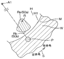
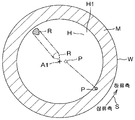
이 발명의 일 실시 형태에서는, 상기 건조 영역이, 상기 착액점에 대해 기판 회전 방향 하류측에 반보다 넓은 영역이 위치하도록 설정된다. 그 때문에, 착액점에 착액된 저표면 장력 액체가 자연스럽게 증발하기 전에 저표면 장력 액체를 한층 확실하게 증발시킬 수 있다.In one embodiment of the present invention, the drying region is set so that a region larger than half of the drying region is located on the downstream side of the substrate rotation direction with respect to the liquid-firing point. Therefore, it is possible to more reliably evaporate the low surface tension liquid before the low surface tension liquid immersed in the liquid developing point naturally evaporates.
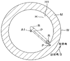
이 발명의 일 실시 형태에서는, 상기 건조 영역이, 선형 (扇形) 의 평면 형상을 가지고 있고, 상기 선형의 사북 (要) 이 상기 착액점으로부터 먼 위치에 배치되고, 상기 선형의 호가 상기 착액점에 가깝게 또한 기판 회전 방향을 따르도록 배치되어 있다.In an embodiment of the present invention, the drying region has a linear fan shape, and the linear convex portion is disposed at a position far from the liquid point, and the linear arc is located at the liquid point And is arranged so as to follow the rotation direction of the substrate.
이 방법에 의하면, 선형의 평면 형상을 갖는 건조 영역에 있어서, 그 선형의 사북이 착액점으로부터 먼 위치에 배치되고, 그 선형의 호가 착액점의 근처에 배치되어 있다. 이로써, 선형의 호가 사북보다 기판의 둘레 가장자리측에 위치하므로, 기판 상면의 각 부가 건조 헤드의 대향면에 대향하는 시간, 즉 건조 시간의 차를 저감할 수 있다. 따라서, 기판의 상면의 건조 불균일을 저감할 수 있다.According to this method, in a dry region having a linear planar shape, the linear north-south is arranged at a position far from the liquid-access point, and the linear arc is disposed near the liquid-liquid point. As a result, the linear arc is located closer to the periphery of the substrate than the convex portion, so that the difference in time between the portions of the upper surface of the substrate facing the opposed surfaces of the drying head, i.e., the drying time can be reduced. Therefore, drying unevenness on the upper surface of the substrate can be reduced.
이 발명의 일 실시 형태에서는, 상기 저표면 장력 액체 노즐과 상기 건조 헤드가 공통의 이동 부재에 지지되어 있고, 상기 착액점 이동 공정 및 상기 건조 영역 이동 공정이, 상기 이동 부재를 이동시키는 공정을 포함한다.In an embodiment of the present invention, the low surface tension liquid nozzle and the drying head are supported by a common moving member, and the liquid-mobility point moving step and the drying area moving step include a step of moving the moving member do.
이 방법에 의하면, 착액점 이동 공정 및 건조 영역 이동 공정에 있어서, 저표면 장력 액체 노즐과 건조 헤드를 공통으로 지지하는 이동 부재를 이동시킴으로써, 저표면 장력 액체 노즐과 건조 헤드의 사이의 거리가 일정하게 유지된다. 따라서, 기판의 상면 전체를 균등한 조건으로 건조시킬 수 있으므로, 기판의 상면의 건조 불균일을 저감할 수 있다.According to this method, by moving the moving member that commonly supports the low surface tension liquid nozzle and the drying head in the liquidus point moving step and the drying area moving step, the distance between the low surface tension liquid nozzle and the drying head is constant Lt; / RTI > Therefore, the entire top surface of the substrate can be dried under even conditions, and drying irregularity on the top surface of the substrate can be reduced.
이 발명의 일 실시 형태에서는, 상기 건조 헤드가, 불활성 가스를 공급하는 불활성 가스 공급 헤드이다. 이로써, 저습도 공간의 습도를 불활성 가스에 의해 저감시킬 수 있다. 따라서, 기판의 상면으로부터 저표면 장력 액체를 신속하게 증발시킬 수 있으므로, 기판의 상면을 신속하게 건조시킬 수 있다.In one embodiment of the present invention, the drying head is an inert gas supply head for supplying an inert gas. Thereby, the humidity of the low humidity space can be reduced by the inert gas. Therefore, the low surface tension liquid can be rapidly evaporated from the upper surface of the substrate, and the upper surface of the substrate can be dried quickly.
이 발명의 일 실시 형태에서는, 상기 대향면이, 기판의 상면으로부터 상방으로 함몰되어 불활성 가스 저류 공간을 형성하고 있고, 상기 불활성 가스 공급 헤드가, 상기 불활성 가스 저류 공간에 불활성 가스를 공급하는 불활성 가스 도입구를 포함한다.According to an embodiment of the present invention, the opposing surface is recessed upward from the upper surface of the substrate to form an inert gas storage space, and the inert gas supply head includes an inert gas supplying inert gas to the inert gas storage space And an introduction port.
이 방법에 의하면, 대향면이, 기판의 상면으로부터 상방으로 함몰되어 불활성 가스 저류 공간을 형성하고 있다. 불활성 가스 저류 공간에는, 불활성 가스 도입구로부터 공급된 불활성 가스가 저류된다. 그 때문에, 불활성 가스 저류 공간에 저류된 불활성 가스에 의해 기판의 상면에 남은 저표면 장력 액체를 증발시킬 수 있다. 따라서, 건조 영역의 저표면 장력 액체를 보다 한층 신속하게 증발시킬 수 있다.According to this method, the opposing surface is recessed upward from the upper surface of the substrate to form an inert gas storage space. In the inert gas storage space, the inert gas supplied from the inert gas inlet is stored. Therefore, the low surface tension liquid left on the upper surface of the substrate can be evaporated by the inert gas stored in the inert gas storage space. Thus, the low surface tension liquid in the drying zone can be evaporated even more quickly.
이 발명의 일 실시 형태에서는, 상기 불활성 가스 공급 헤드가, 상기 불활성 가스 저류 공간을 배기하는 배기구를 추가로 포함한다.In one embodiment of the present invention, the inert gas supply head further includes an exhaust port for exhausting the inert gas storage space.
이 방법에 의하면, 배기구가 불활성 가스 저류 공간을 배기한다. 이로써, 기판의 상면으로부터 증발하여 증기가 된 저표면 장력 액체가, 불활성 가스 저류 공간을 통하여 저습도 공간으로부터 배제된다. 이로써, 저습도 공간을 보다 한층 저습도로 유지할 수 있으므로, 건조 영역의 저표면 장력 액체를 보다 한층 신속하게 증발시킬 수 있다.According to this method, the exhaust port exhausts the inert gas storage space. Thereby, the low surface tension liquid evaporated from the upper surface of the substrate and vaporized is excluded from the low humidity space through the inert gas storage space. Thereby, the low-humidity space can be maintained at a lower humidity, so that the low surface tension liquid in the drying zone can be evaporated more quickly.
이 발명의 일 실시 형태에서는, 상기 대향면이, 기판의 상면에 평행한 평탄면이며, 상기 대향면에 복수의 불활성 가스 토출구가 형성되어 있다. 또, 상기 불활성 가스 공급 헤드가, 상기 복수의 불활성 가스 토출구에 연통하는 불활성 가스 저류 공간과, 상기 불활성 가스 저류 공간에 불활성 가스를 공급하는 불활성 가스 도입구를 포함한다.In an embodiment of the present invention, the opposed surface is a flat surface parallel to the upper surface of the substrate, and a plurality of inert gas outlets are formed on the opposed surface. In addition, the inert gas supply head may include an inert gas storage space communicating with the plurality of inert gas discharge openings, and an inert gas inlet for supplying inert gas to the inert gas storage space.
이 방법에 의하면, 불활성 가스 도입구로부터의 불활성 가스는 불활성 가스 저류 공간에 공급된다. 불활성 가스 저류 공간은, 기판의 상면에 평행한 평탄면인 대향면에 형성된 복수의 불활성 가스 토출구에 연통되어 있다. 그 때문에, 불활성 가스가 1 개의 토출구로부터 공급되는 경우와 비교해서, 넓은 범위에 균일하게 불활성 가스를 공급할 수 있기 때문에, 습도 불균일이 적은 저습도 공간을 형성할 수 있다. 따라서, 건조 영역의 저표면 장력 액체를 신속하게 증발시킬 수 있고, 또한, 기판의 상면의 건조 불균일을 저감할 수 있다. 또, 불활성 가스 토출구가 복수 있음으로써, 기판의 상면에 공급되는 불활성 가스의 기세를 저감할 수 있다. 그 때문에, 기판의 상면에 국부적으로 큰 외력이 작용하는 것을 억제할 수 있다.According to this method, the inert gas from the inert gas inlet is supplied to the inert gas storage space. The inert gas storage space communicates with a plurality of inert gas discharge openings formed in the opposite surface which is a flat surface parallel to the upper surface of the substrate. Therefore, as compared with the case where the inert gas is supplied from one discharge port, the inert gas can be uniformly supplied over a wide range, so that a low humidity space having less humidity unevenness can be formed. Therefore, the low surface tension liquid in the drying region can be quickly evaporated, and drying irregularity on the upper surface of the substrate can be reduced. Also, by having a plurality of inert gas discharge ports, the momentum of the inert gas supplied to the upper surface of the substrate can be reduced. Therefore, a large external force acting locally on the upper surface of the substrate can be suppressed.
이 발명의 일 실시 형태에서는, 상기 건조 헤드가, 상기 건조 영역을 가열하는 히터 유닛을 포함한다. 이로써, 건조 영역의 저표면 장력 액체의 증발을 한층 촉진할 수 있다.In one embodiment of the present invention, the drying head includes a heater unit for heating the drying region. This can further promote the evaporation of the low surface tension liquid in the drying zone.
이 발명의 일 실시 형태에서는, 상기 건조 헤드가, 상기 대향면과 상기 건조 영역의 사이의 공간을 배기하는 배기 유닛을 포함한다.In one embodiment of the present invention, the drying head includes an exhaust unit that exhausts a space between the opposed surface and the drying region.
이 방법에 의하면, 대향면과 건조 영역의 사이의 공간을 배기하는 배기 유닛에 의해, 저표면 장력 액체의 증기를 저습도 공간으로부터 배제할 수 있다. 따라서, 건조 영역의 저표면 장력 액체를 한층 신속하게 증발시킬 수 있다.According to this method, the vapor of the low surface tension liquid can be excluded from the low humidity space by the exhaust unit that exhausts the space between the facing surface and the drying region. Thus, the low surface tension liquid in the drying zone can be evaporated even more quickly.
이 발명의 일 실시 형태에서는, 기판 처리 장치는, 기판을 수평으로 유지하는 기판 유지 유닛과, 상기 기판 유지 유닛에 유지된 기판의 상면에 물보다 표면 장력이 낮은 저표면 장력 액체를 공급하는 저표면 장력 액체 공급 유닛과, 상기 기판 유지 유닛에 유지된 기판의 상면에 형성되는 상기 저표면 장력 액체의 액막의 중앙 영역에 개구를 형성하는 개구 형성 유닛과, 상기 기판 유지 유닛에 유지된 기판의 상면에 대향하고, 기판보다 평면에서 보아 사이즈가 작은 대향면을 가지며, 상기 대향면과 기판의 상면의 사이의 공간에 그 공간 외보다도 저습도인 저습도 공간을 형성함으로써 기판의 상면을 건조시키는 건조 헤드와, 상기 기판 유지 유닛에 유지된 기판의 상면을 따라 상기 건조 헤드를 이동시키는 건조 헤드 이동 유닛을 포함한다.According to an embodiment of the present invention, there is provided a substrate processing apparatus comprising: a substrate holding unit for holding a substrate horizontally; a low-surface-tension liquid supply unit for supplying a low- An opening forming unit for forming an opening in a central region of the liquid film of the low surface tension liquid formed on the upper surface of the substrate held by the substrate holding unit; A drying head for drying the upper surface of the substrate by forming a low humidity space having a lower humidity than the space in the space between the opposed surface and the upper surface of the substrate, And a drying head moving unit for moving the drying head along an upper surface of the substrate held by the substrate holding unit.
이 구성에 의하면, 기판 상에 저표면 장력 액체의 액막이 형성되고, 그 액막의 중앙 영역에 개구가 형성된다. 그 개구의 내측에 설정된 건조 영역에 대향하는 대향면과 건조 영역의 사이의 공간에는, 그 공간 외보다도 저습도인 저습도 공간이 형성된다. 그 때문에, 건조 영역에 남은 저표면 장력 액체를 신속하게 증발시킬 수 있다.According to this structure, a liquid film of a low surface tension liquid is formed on the substrate, and an opening is formed in the central region of the liquid film. A low humidity space having a lower humidity than the space outside the space is formed in the space between the opposed surface facing the drying area set inside the opening and the drying area. Therefore, the low surface tension liquid remaining in the drying zone can be rapidly evaporated.
이 발명의 일 실시 형태에서는, 상기 기판 처리 장치가, 상기 저표면 장력 액체 공급 유닛, 상기 개구 형성 유닛, 상기 건조 헤드 및 상기 건조 헤드 이동 유닛을 제어하는 컨트롤러를 추가로 포함한다. 그리고, 상기 컨트롤러가, 상기 저표면 장력 액체 공급 유닛으로부터 기판의 상면에 저표면 장력 액체를 공급시키고, 상기 기판의 상면에 저표면 장력 액체의 액막을 형성하는 액막 형성 공정과, 상기 개구 형성 유닛에 의해 상기 액막의 중앙 영역에 개구를 형성하는 개구 형성 공정과, 상기 개구를 넓힘으로써 상기 기판의 상면으로부터 상기 액막을 배제하는 액막 배제 공정과, 상기 저표면 장력 액체 공급 유닛으로부터 공급되는 저표면 장력 액체의 착액점을 상기 개구의 외측에 설정하여 상기 개구의 넓어짐에 추종하도록 상기 착액점을 이동시키는 착액점 이동 공정과, 상기 개구의 내측에 설정한 건조 영역에 상기 건조 헤드의 상기 대향면을 대향시켜, 상기 개구의 넓어짐에 추종하도록 상기 건조 영역 및 상기 대향면을 이동시키는 건조 영역 이동 공정을 실행하도록 프로그램되어 있다.In one embodiment of the present invention, the substrate processing apparatus further includes a controller for controlling the low surface tension liquid supply unit, the opening forming unit, the drying head, and the drying head moving unit. The controller may further include a liquid film forming step of supplying a low surface tension liquid to the upper surface of the substrate from the low surface tension liquid supply unit and forming a liquid film of low surface tension liquid on the upper surface of the substrate, A liquid film removing step of removing the liquid film from the upper surface of the substrate by widening the opening to form an opening in a central region of the liquid film by a low surface tension liquid supply unit; A liquidus point moving step of moving the liquid point so as to follow the spreading of the opening by setting the liquidus point of the drying liquid in the outside of the opening so that the facing surface of the drying head is opposed to the drying region set inside the opening , A drying zone for moving the drying zone and the facing surface to follow the widening of the opening It is programmed to execute the process.
이 구성에 의하면, 건조 영역 및 대향면은, 저표면 장력 액체의 액막의 개구의 넓어짐에 추종한다. 그 때문에, 저표면 장력 액체의 액막이 배제된 후에 기판의 상면에 남은 저표면 장력 액체를 신속하게 증발시킬 수 있다. 게다가, 대향면이 대향하는 건조 영역은 비교적 넓기 때문에, 기판의 상면에 국부적인 외력이 작용하기 어렵다.According to this configuration, the drying zone and the opposite surface follow the widening of the opening of the liquid film of the low surface tension liquid. Therefore, the low surface tension liquid remaining on the upper surface of the substrate can be rapidly evaporated after the liquid film of the low surface tension liquid is excluded. In addition, since the drying region opposed to the opposed surface is relatively wide, a local external force hardly acts on the upper surface of the substrate.
한편, 대향면은, 기판보다 평면에서 보아 사이즈가 작다. 그 때문에, 저표면 장력 액체 노즐을 회피한 위치, 즉 기판의 상면에 충분히 가까운 위치에 건조 헤드를 배치하면서 대향면을 이동시킬 수 있다. 이로써, 건조 영역에 남은 저표면 장력 액체를 한층 신속하게 증발시킬 수 있다.On the other hand, the opposite surface is smaller in size than the substrate. Therefore, the opposing surface can be moved while arranging the drying head at a position at which the low surface tension liquid nozzle is avoided, that is, at a position sufficiently close to the upper surface of the substrate. Thereby, the low surface tension liquid remaining in the drying zone can be evaporated even more quickly.
건조 영역이 개구의 내측에 설정되어 있고, 착액점이 개구의 외측에 설정되어 있으므로, 기판의 상면으로부터 액막이 배제될 때까지의 동안, 액막으로부터 저표면 장력 액체가 자연스럽게 증발하는 것을 억제하면서, 충분한 양의 저표면 장력 액체가 액막에 공급된다. 그 때문에, 개구의 넓어짐에 의해 액막이 배제되기 전에, 국소적인 액막의 증발에서 기인하여 액막 균열이 발생하는 것을 억제할 수 있다.Since the drying region is set on the inner side of the opening and the liquid immersion point is set on the outer side of the opening, it is possible to prevent the low surface tension liquid from naturally evaporating from the liquid film while the liquid film is excluded from the upper surface of the substrate, Low surface tension liquid is supplied to the liquid film. Therefore, it is possible to prevent liquid film cracking from occurring due to evaporation of the local liquid film before the liquid film is excluded by the widening of the opening.
따라서, 저표면 장력 액체를 기판의 상면으로부터 양호하게 배제할 수 있다.Therefore, the low surface tension liquid can be preferably excluded from the upper surface of the substrate.
이 발명의 일 실시 형태에서는, 상기 컨트롤러가, 상기 건조 영역 이동 공정 에 있어서, 상기 착액점의 이동에 추종하도록, 상기 착액점의 이동 궤적을 따라 상기 건조 영역을 이동시키는 공정을 실행하도록 프로그램되어 있다. 그 때문에, 착액점에 착액한 저표면 장력 액체가 자연스럽게 증발하기 전에, 저표면 장력 액체를 건조 헤드에 의해 신속하게 증발시킬 수 있다.In an embodiment of the present invention, the controller is programmed to execute a step of moving the drying region along a movement trajectory of the pickling point so as to follow the movement of the pickling point in the drying region moving step . Therefore, the low surface tension liquid can be rapidly evaporated by the drying head before the low surface tension liquid adhering to the liquidation point naturally evaporates.
이 발명의 일 실시 형태에서는, 상기 개구 형성 유닛이, 상기 기판 유지 유닛에 유지된 기판의 중앙 영역을 향하여 불활성 가스를 분사하는 불활성 가스 공급 유닛을 포함한다. 또, 상기 컨트롤러가, 상기 개구 형성 공정에 있어서, 상기 불활성 가스 공급 유닛으로부터 불활성 가스를 공급시키는 불활성 가스 분사 공정을 실행하고, 또한, 상기 액막 배제 공정이 완료될 때까지 상기 불활성 가스 분사 공정을 계속하도록 프로그램되어 있다.In an embodiment of the present invention, the aperture forming unit includes an inert gas supplying unit that injects an inert gas toward a central region of the substrate held by the substrate holding unit. The controller may perform an inert gas injection step of supplying the inert gas from the inert gas supply unit in the opening forming step and continue the inert gas injection step until the liquid film elimination step is completed .
이 구성에 의하면, 개구 형성 공정에 있어서, 액막의 중앙 영역을 향하여 불활성 가스를 분사함으로써, 개구를 효율적으로, 또한 확실하게 중앙 영역에 형성 할 수 있다. 또, 불활성 가스의 분사가, 액막 배제 공정이 완료될 때까지 계속된다. 이로써, 개구의 넓어짐이 촉진되어, 저표면 장력 액체를 보다 한층 신속하게 기판 외로 배제할 수 있다.According to this configuration, in the opening forming step, the opening can be formed efficiently and surely in the central region by jetting the inert gas toward the central region of the liquid film. Further, the injection of the inert gas continues until the liquid film removal process is completed. As a result, the widening of the opening is promoted, and the low surface tension liquid can be excluded from the substrate more rapidly.
이 발명의 일 실시 형태에서는, 상기 기판 처리 장치가, 상기 기판 유지 유닛에 유지된 기판을 연직 방향을 따른 소정의 회전 축선 둘레로 회전시키는 기판 회전 유닛을 추가로 포함한다. 또, 상기 컨트롤러가, 상기 액막 배제 공정과 병행해서 상기 기판을 회전시키는 기판 회전 공정을 실행하도록 프로그램되어 있다.In one embodiment of the present invention, the substrate processing apparatus further includes a substrate rotating unit that rotates the substrate held by the substrate holding unit about a predetermined rotation axis along the vertical direction. Further, the controller is programmed to execute a substrate rotating process for rotating the substrate in parallel with the liquid film removing process.
이 구성에 의하면, 액막 배제 공정과 병행해서 기판을 회전시키므로, 기판의 회전에 의해 발생하는 원심력에 의해 개구의 넓어짐을 촉진할 수 있다. 이로써, 저표면 장력 액체를 한층 신속하게 기판 외로 배제할 수 있다. 또, 기판의 회전에 수반하여, 액막의 개구의 외측에서는, 저표면 장력 액체의 착액점이 기판을 주사하고, 개구의 내측에서는, 건조 영역이 기판을 주사한다. 그것에 의해, 기판의 상면 전체에 대해 균일한 건조 처리를 실시할 수 있다.According to this configuration, since the substrate is rotated in parallel with the liquid film removal step, the widening of the opening can be promoted by the centrifugal force generated by the rotation of the substrate. Thereby, the low surface tension liquid can be excluded from the substrate more quickly. With the rotation of the substrate, the substrate is scanned by a liquid-immersion point of the low surface tension liquid on the outside of the opening of the liquid film, and on the inside of the opening, the dry region scans the substrate. This makes it possible to perform a uniform drying process on the entire upper surface of the substrate.
이 발명의 일 실시 형태에서는, 상기 컨트롤러가, 상기 기판 회전 공정에 있어서, 기판의 회전을 서서히 감속시키는 회전 감속 공정을 실행하도록 프로그램되어 있다.In one embodiment of the present invention, the controller is programmed to execute a rotation deceleration process for gradually decelerating the rotation of the substrate in the substrate rotation process.
이 구성에 의하면, 액막 배제 공정과 병행해서 실행되는 기판 회전 공정에 있어서, 기판의 회전을 서서히 감속시킴으로써, 기판의 상면의 건조 불균일을 저감 할 수 있다.According to this configuration, in the substrate rotation process executed in parallel with the liquid film removal process, the rotation of the substrate is gradually decelerated, whereby the drying unevenness on the upper surface of the substrate can be reduced.
이 발명의 일 실시 형태에서는, 상기 컨트롤러는, 상기 착액점에 대해 기판 회전 방향 하류측에 반보다 넓은 영역이 위치하도록 상기 건조 영역을 설정하도록 프로그램되어 있다. 그 때문에, 착액점에 착액된 저표면 장력 액체가 자연스럽게 증발하기 전에 저표면 장력 액체를 한층 확실하게 증발시킬 수 있다.In one embodiment of the present invention, the controller is programmed to set the drying region such that a region larger than half of the substrate is located on the downstream side of the substrate rotation direction with respect to the liquid-firing point. Therefore, it is possible to more reliably evaporate the low surface tension liquid before the low surface tension liquid immersed in the liquid developing point naturally evaporates.
이 발명의 일 실시 형태에서는, 상기 대향면이, 선형의 평면 형상을 가지고 있고, 상기 선형의 사북이 상기 착액점으로부터 먼 위치에 배치되고, 상기 선형의 호가 상기 착액점에 가깝게 또한 기판 회전 방향을 따르도록 배치되어 있다.According to an embodiment of the present invention, the opposing face has a linear planar shape, and the linear convex portion is disposed at a position farther from the liquid fitting point, and the linear arc is disposed close to the liquid- Respectively.
이 구성에 의하면, 선형의 평면 형상을 갖는 대향면에 있어서, 그 선형의 사북이 착액점으로부터 먼 위치에 배치되고, 그 선형의 호가 착액점의 근처에 배치되어 있다. 이로써, 사북보다 기판 회전 방향으로 큰 호를, 사북보다 기판의 둘레 가장자리측에 배치할 수 있다. 그 때문에, 선형의 호가 기판의 둘레 가장자리측에 위치하므로, 기판 상면의 각 부가 건조 헤드의 대향면에 대향하는 시간, 즉 건조 시간의 차를 저감할 수 있다. 따라서, 기판의 상면의 건조 불균일을 저감할 수 있다.According to this configuration, in the facing surface having a linear planar shape, the linear north-south is disposed at a position far from the liquid-access point, and the linear arc is disposed near the liquid-contact point. This makes it possible to arrange a large arc in the substrate rotation direction, rather than a cylindrical shape, on the peripheral edge side of the substrate relative to the cylindrical shape. Therefore, since the linear arc is located on the peripheral edge side of the substrate, it is possible to reduce the difference in time between the opposed surfaces of the respective portions of the upper surface of the substrate, that is, the drying time. Therefore, drying unevenness on the upper surface of the substrate can be reduced.
이 발명의 일 실시 형태에서는, 상기 저표면 장력 액체 공급 유닛이, 상기 기판 유지 유닛에 유지된 기판의 상면을 향하여 저표면 장력 액체를 공급하는 저표면 장력 액체 노즐을 포함한다. 또, 기판 처리 장치는, 상기 저표면 장력 액체 노즐과 상기 건조 헤드를 공통으로 지지하고, 상기 저표면 장력 액체 노즐 및 상기 건조 헤드를 상기 기판의 상방에서 이동시키는 이동 부재를 추가로 포함한다. 또, 상기 건조 헤드 이동 유닛이, 상기 이동 부재를 이동시킨다.In one embodiment of the present invention, the low surface tension liquid supply unit includes a low surface tension liquid nozzle for supplying a low surface tension liquid toward the upper surface of the substrate held by the substrate holding unit. The substrate processing apparatus further includes a moving member for supporting the low surface tension liquid nozzle and the drying head in common, and moving the low surface tension liquid nozzle and the drying head from above the substrate. Further, the drying head moving unit moves the moving member.
이 구성에 의하면, 저표면 장력 액체 노즐과 건조 헤드를 공통으로 지지하는 이동 부재를 이동시킴으로써, 저표면 장력 액체 노즐과 건조 헤드의 사이의 거리가 일정하게 유지된다. 따라서, 기판의 상면 전체를 균등한 조건으로 건조시킬 수 있으므로, 건조 불균일을 저감할 수 있다.According to this configuration, by moving the moving member that commonly supports the low surface tension liquid nozzle and the drying head, the distance between the low surface tension liquid nozzle and the drying head is kept constant. Therefore, the entire upper surface of the substrate can be dried under uniform conditions, and drying irregularity can be reduced.
이 발명의 일 실시 형태에서는, 상기 건조 헤드가, 불활성 가스를 공급하는 불활성 가스 공급 헤드이다. 그 때문에, 저습도 공간의 습도를 불활성 가스에 의해 저감시킬 수 있다. 이로써, 기판의 상면으로부터 저표면 장력 액체를 신속하게 증발시킬 수 있으므로, 기판의 상면을 신속하게 건조시킬 수 있다.In one embodiment of the present invention, the drying head is an inert gas supply head for supplying an inert gas. Therefore, the humidity in the low-humidity space can be reduced by the inert gas. Thereby, the low surface tension liquid can be rapidly evaporated from the upper surface of the substrate, and therefore, the upper surface of the substrate can be dried quickly.
이 발명의 일 실시 형태에서는, 상기 대향면이, 상기 기판 유지 유닛에 유지된 기판의 상면으로부터 상방으로 함몰되어 불활성 가스 저류 공간을 형성하고 있다. 또, 상기 불활성 가스 공급 헤드가, 상기 불활성 가스 저류 공간에 불활성 가스를 공급하는 불활성 가스 도입구를 포함한다.In an embodiment of the present invention, the opposing surface is recessed upward from the upper surface of the substrate held by the substrate holding unit to form an inert gas storage space. The inert gas supply head includes an inert gas inlet for supplying an inert gas to the inert gas storage space.
이 구성에 의하면, 대향면이, 기판의 상면으로부터 상방으로 함몰되어 불활성 가스 저류 공간을 형성하고 있다. 불활성 가스 저류 공간에는, 불활성 가스 도입구로부터 공급된 불활성 가스가 저류된다. 그 때문에, 불활성 가스 저류 공간에 저류된 불활성 가스에 의해 기판의 상면에 남은 저표면 장력 액체를 증발시킬 수 있다. 따라서, 기판의 상면의 저표면 장력 액체를 보다 한층 신속하게 증발시킬 수 있다.According to this structure, the opposing surface is recessed upward from the upper surface of the substrate to form an inert gas storage space. In the inert gas storage space, the inert gas supplied from the inert gas inlet is stored. Therefore, the low surface tension liquid left on the upper surface of the substrate can be evaporated by the inert gas stored in the inert gas storage space. Therefore, the low surface tension liquid on the upper surface of the substrate can be evaporated even more quickly.
이 발명의 일 실시 형태에서는, 상기 불활성 가스 공급 헤드가, 상기 불활성 가스 저류 공간을 배기하는 배기구를 추가로 포함한다.In one embodiment of the present invention, the inert gas supply head further includes an exhaust port for exhausting the inert gas storage space.
이 구성에 의하면, 불활성 가스 저류 공간을 배기하는 배기구에 의해, 기판의 상면으로부터 증발하여 증기가 된 저표면 장력 액체가, 불활성 가스 저류 공간을 통하여 저습도 공간으로부터 배제된다. 이로써, 저습도 공간을 보다 한층 저습도로 유지할 수 있으므로, 기판의 상면의 저표면 장력 액체를 보다 한층 신속하게 증발시킬 수 있다.According to this structure, the low-surface tension liquid evaporated from the upper surface of the substrate and vaporized by the exhaust port for exhausting the inert gas storage space is excluded from the low humidity space through the inert gas storage space. Thus, the low-humidity space can be maintained at a lower humidity, so that the low surface tension liquid on the upper surface of the substrate can be evaporated more quickly.
이 발명의 일 실시 형태에서는, 상기 대향면이, 기판의 상면에 평행한 평탄면이며, 상기 대향면에 복수의 불활성 가스 토출구가 형성되어 있다. 또, 상기 불활성 가스 공급 헤드는, 상기 복수의 불활성 가스 토출구에 연통하는 불활성 가스 저류 공간과, 상기 불활성 가스 저류 공간에 불활성 가스를 공급하는 불활성 가스 도입구를 포함한다.In an embodiment of the present invention, the opposed surface is a flat surface parallel to the upper surface of the substrate, and a plurality of inert gas outlets are formed on the opposed surface. The inert gas supply head includes an inert gas storage space communicating with the plurality of inert gas discharge openings and an inert gas inlet for supplying inert gas to the inert gas storage space.
이 구성에 의하면, 불활성 가스 도입구로부터의 불활성 가스는 불활성 가스 저류 공간에 공급된다. 불활성 가스 저류 공간은, 기판의 상면에 평행한 평탄면인 대향면에 형성된 복수의 불활성 가스 토출구에 연통되어 있다. 그 때문에, 불활성 가스가 1 개의 토출구로부터 공급되는 경우와 비교해서, 넓은 범위에 균일하게 불활성 가스를 공급할 수 있기 때문에, 습도 불균일이 적은 저습도 공간을 형성할 수 있다. 따라서, 기판의 상면의 저표면 장력 액체를, 불균일 없이, 또한 신속하게 증발시킬 수 있다. 또, 불활성 가스 토출구가 복수 있음으로써, 기판의 상면에 공급되는 불활성 가스의 기세를 저감할 수 있다. 그 때문에, 기판의 상면에 국부적으로 큰 외력이 작용하는 것을 억제할 수 있다.According to this configuration, the inert gas from the inert gas inlet is supplied to the inert gas storage space. The inert gas storage space communicates with a plurality of inert gas discharge openings formed in the opposite surface which is a flat surface parallel to the upper surface of the substrate. Therefore, as compared with the case where the inert gas is supplied from one discharge port, the inert gas can be uniformly supplied over a wide range, so that a low humidity space having less humidity unevenness can be formed. Therefore, the low surface tension liquid on the upper surface of the substrate can be evaporated quickly and quickly. Also, by having a plurality of inert gas discharge ports, the momentum of the inert gas supplied to the upper surface of the substrate can be reduced. Therefore, a large external force acting locally on the upper surface of the substrate can be suppressed.
이 발명의 일 실시 형태에서는, 상기 건조 헤드가, 상기 기판 유지 유닛에 유지된 기판의 상면을 가열하는 히터 유닛을 포함한다. 이로써, 기판의 상면의 저표면 장력 액체의 증발을 한층 촉진할 수 있다.In one embodiment of the present invention, the drying head includes a heater unit that heats the upper surface of the substrate held by the substrate holding unit. This makes it possible to further promote the evaporation of the low surface tension liquid on the upper surface of the substrate.
이 발명의 일 실시 형태에서는, 상기 건조 헤드가, 상기 대향면과 상기 기판 유지 유닛에 유지된 기판의 상면의 사이의 공간을 배기하는 배기 유닛을 포함한다.In one embodiment of the present invention, the drying head includes an exhaust unit for exhausting a space between the opposed surface and the upper surface of the substrate held by the substrate holding unit.
이 구성에 의하면, 대향면과 기판의 상면의 사이의 공간을 배기하는 배기 유닛에 의해, 저표면 장력 액체의 증기를 저습도 공간으로부터 배제할 수 있다. 따라서, 기판의 상면의 저표면 장력 액체를 한층 신속하게 증발시킬 수 있다.According to this structure, the vapor of the low surface tension liquid can be excluded from the low humidity space by the exhaust unit that exhausts the space between the facing surface and the upper surface of the substrate. Therefore, the low surface tension liquid on the upper surface of the substrate can be evaporated more quickly.
본 발명에 있어서의 상기 서술한, 또는 추가로 다른 목적, 특징 및 효과는, 첨부 도면을 참조하여 다음에 기술하는 실시 형태의 설명에 의해 밝혀진다.The above and other objects, features, and advantages of the present invention are apparent from the following description of the embodiments with reference to the accompanying drawings.
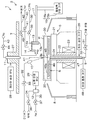
도 1 은, 이 발명의 제 1 실시 형태에 관련된 기판 처리 장치의 내부의 레이아웃을 설명하기 위한 도해적인 평면도이다.
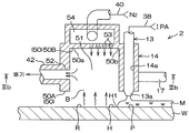
도 2 는, 상기 기판 처리 장치에 구비된 처리 유닛의 구성예를 설명하기 위한 도해적인 단면도이다.
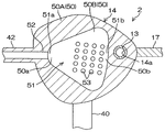
도 3A 는, 상기 처리 유닛에 구비된 건조 헤드의 모식적인 종단면도이다.
도 3B 는, 도 3A 의 IIIb-IIIb 선을 따른 횡단면도이다.
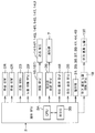
도 4 는, 상기 기판 처리 장치의 주요부의 전기적 구성을 설명하기 위한 블록도이다.
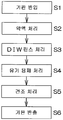
도 5 는, 상기 기판 처리 장치에 의한 기판 처리의 일례를 설명하기 위한 흐름도이다.
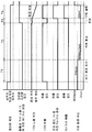
도 6 은, 유기 용제 처리 (도 5 의 S4) 의 상세를 설명하기 위한 타임 차트이다.
도 7A 는, 유기 용제 처리 (도 5 의 S4) 의 모습을 설명하기 위한 도해적인 단면도이다.
도 7B 는, 유기 용제 처리 (도 5 의 S4) 의 모습을 설명하기 위한 도해적인 단면도이다.
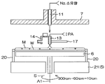
도 7C 는, 유기 용제 처리 (도 5 의 S4) 의 모습을 설명하기 위한 도해적인 단면도이다.
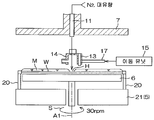
도 7D 는, 유기 용제 처리 (도 5 의 S4) 의 모습을 설명하기 위한 도해적인 단면도이다.
도 8A 는, 도 7D 에 나타내는 구멍 넓힘 스텝에 있어서의 착액점 및 건조 영역의 이동 궤적을 모식적으로 나타낸 평면도이다.
도 8B 는, 도 8A 의 착액점 및 건조 영역의 주변의 확대도이다.
도 9 는, 제 1 실시 형태의 제 1 변형예에 관련된 처리 유닛에 구비된 건조 헤드를 나타낸 모식적인 단면도이다.
도 10 은, 제 1 실시 형태의 제 2 변형예에 관련된 처리 유닛에 구비된 건조 헤드를 나타낸 모식적인 단면도이다.
도 11 은, 제 1 실시 형태의 제 3 변형예에 관련된 처리 유닛에 구비된 건조 헤드를 나타낸 모식적인 단면도이다.
도 12 는, 제 1 실시 형태의 제 4 변형예에 관련된 처리 유닛에 구비된 건조 헤드를 나타낸 모식적인 단면도이다.
도 13 은, 제 1 실시 형태의 제 5 변형예에 관련된 처리 유닛에 구비된 건조 헤드를 나타낸 모식적인 단면도이다.
도 14 는, 본 발명의 제 2 실시 형태에 관련된 기판 처리 장치에 구비된 처리 유닛의 구성예를 설명하기 위한 도해적인 단면도이다.
도 15 는, 제 2 실시 형태에 있어서의 구멍 넓힘 스텝에 있어서의 착액점 및 건조 영역의 이동 궤적을 모식적으로 나타낸 평면도이다.
도 16 은, 표면 장력에 의한 패턴 도괴의 원리를 설명하기 위한 도해적인 단면도이다.1 is a schematic plan view for explaining an internal layout of a substrate processing apparatus according to a first embodiment of the present invention.
2 is a schematic sectional view for explaining a configuration example of a processing unit provided in the substrate processing apparatus.
3A is a schematic longitudinal sectional view of a drying head provided in the processing unit.
FIG. 3B is a cross-sectional view taken along line IIIb-IIIb of FIG. 3A.
4 is a block diagram for explaining an electrical configuration of a main portion of the substrate processing apparatus.
5 is a flowchart for explaining an example of substrate processing by the substrate processing apparatus.
Fig. 6 is a time chart for explaining details of the organic solvent treatment (S4 in Fig. 5).
7A is a schematic sectional view for explaining a state of the organic solvent treatment (S4 in Fig. 5).
FIG. 7B is a schematic sectional view for explaining the state of the organic solvent treatment (S4 in FIG. 5).
7C is a schematic sectional view for explaining a state of the organic solvent treatment (S4 in Fig. 5).
7D is a schematic sectional view for explaining the state of the organic solvent treatment (S4 in Fig. 5).
Fig. 8A is a plan view schematically showing the movement locus of the liquid-contact point and the dry region in the hole widening step shown in Fig. 7D. Fig.
Fig. 8B is an enlarged view of the periphery of the liquid point and the drying region of Fig. 8A. Fig.
9 is a schematic cross-sectional view showing a drying head provided in the processing unit according to the first modification of the first embodiment.
10 is a schematic cross-sectional view showing a drying head provided in the processing unit according to the second modification of the first embodiment.
11 is a schematic cross-sectional view showing a drying head provided in the processing unit according to the third modification of the first embodiment.
12 is a schematic cross-sectional view showing a drying head provided in the processing unit according to the fourth modification of the first embodiment.
13 is a schematic cross-sectional view showing a drying head provided in the processing unit according to the fifth modification of the first embodiment.
14 is a diagrammatic sectional view for explaining a structural example of a processing unit provided in the substrate processing apparatus according to the second embodiment of the present invention.
Fig. 15 is a plan view schematically showing the movement locus of the liquid-contact point and the dry region in the hole widening step in the second embodiment. Fig.
Fig. 16 is a schematic sectional view for explaining the principle of patterning by surface tension. Fig.
<제 1 실시 형태>≪ First Embodiment >
도 1 은, 이 발명의 제 1 실시 형태에 관련된 기판 처리 장치 (1) 의 내부의 레이아웃을 설명하기 위한 도해적인 평면도이다. 기판 처리 장치 (1) 는, 실리콘 웨이퍼 등의 기판 (W) 을 1 매씩 처리하는 매엽식의 장치이다. 이 실시 형태에서는, 기판 (W) 은, 원형상의 기판이다. 기판 (W) 의 직경은 예를 들어 300 mm 이다. 기판 (W) 의 표면에는, 미세한 패턴 (도 16 참조) 이 형성되어 있다. 기판 처리 장치 (1) 는, 처리액으로 기판 (W) 을 처리하는 복수의 처리 유닛 (2) 과, 처리 유닛 (2) 에서 처리되는 복수 매의 기판 (W) 을 수용하는 캐리어 (C) 가 재치되는 로드 포트 (LP) 와, 로드 포트 (LP) 와 처리 유닛 (2) 의 사이에서 기판 (W) 을 반송하는 반송 로봇 (IR 및 CR) 과, 기판 처리 장치 (1) 를 제어하는 컨트롤러 (3) 를 포함한다. 반송 로봇 (IR) 은, 캐리어 (C) 와 반송 로봇 (CR) 의 사이에서 기판 (W) 을 반송한다. 반송 로봇 (CR) 은, 반송 로봇 (IR) 과 처리 유닛 (2) 의 사이에서 기판 (W) 을 반송한다. 복수의 처리 유닛 (2) 은, 예를 들어, 동일한 구성을 가지고 있다.1 is a schematic plan view for explaining the layout of the inside of the substrate processing apparatus 1 according to the first embodiment of the present invention. The substrate processing apparatus 1 is a single wafer type apparatus for processing substrates W such as a silicon wafer one by one. In this embodiment, the substrate W is a circular substrate. The diameter of the substrate W is, for example, 300 mm. On the surface of the substrate W, a fine pattern (see Fig. 16) is formed. The substrate processing apparatus 1 includes a plurality of
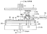
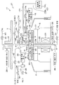
도 2 는, 처리 유닛 (2) 의 구성예를 설명하기 위한 도해적인 단면도이다. 처리 유닛 (2) 은, 1 매의 기판 (W) 을 수평한 자세로 유지하면서, 기판 (W) 의 중심을 통과하는 연직인 회전 축선 (A1) 둘레로 기판 (W) 을 회전시키는 스핀 척 (5) 을 포함한다. 스핀 척 (5) 은, 도시되지 않은 벽면으로 외부로부터 격리되어 있다. 처리 유닛 (2) 은, 기판 (W) 을 하면 (하방측의 주면) 측으로부터 가열하는 히터 기구 (6) 와, 기판 (W) 의 상면 (상방측의 주면) 에 대향해서 기판 (W) 과의 사이의 분위기를 주위의 분위기로부터 차단하는 차단판 (7) 과, 스핀 척 (5) 을 둘러싸는 통형상의 컵 (8) 과, 기판 (W) 의 하면에 처리 유체를 공급하는 하면 노즐 (9) 을 추가로 포함한다.Fig. 2 is a schematic sectional view for explaining a configuration example of the
처리 유닛 (2) 은, 기판 (W) 의 상면에 린스액으로서의 탈이온수 (DIW : Deionized Water) 를 공급하는 DIW 노즐 (10) 과, 기판 (W) 의 상면의 중앙 영역에 질소 가스 (N2) 등의 불활성 가스를 공급하는 불활성 가스 노즐 (11) 과, 기판 (W) 의 상방에서 이동 가능한 이동 노즐 (12) 을 추가로 포함한다. 기판 (W) 의 상면의 중앙 영역이란, 기판 (W) 의 상면에 있어서의 회전 축선 (A1) 과의 교차 위치를 포함하는 기판 (W) 의 상면의 중앙 및 그 근방의 영역이다.The
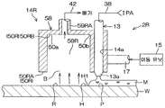
처리 유닛 (2) 은, 물보다 표면 장력이 낮은 저표면 장력 액체로서의 유기 용제 (예를 들어 IPA) 를 기판 (W) 의 상면에 공급하는 유기 용제 노즐 (13) 과, 질소 가스 등의 불활성 가스를 기판 (W) 의 상면에 공급함으로써 기판 (W) 의 상면을 건조시키는 건조 헤드 (14) 를 추가로 포함한다. 본 실시 형태에서는, 건조 헤드 (14) 는, 불활성 가스를 공급하는 불활성 가스 공급 헤드이다.The
처리 유닛 (2) 은, 컵 (8) 을 수용하는 챔버 (16) (도 1 참조) 를 추가로 포함한다. 도시는 생략하지만, 챔버 (16) 에는, 기판 (W) 을 반입/반출하기 위한 반입/반출구가 형성되어 있고, 이 반입/반출구를 개폐하는 셔터 유닛이 구비되어 있다.The
스핀 척 (5) 은, 척 핀 (20) 과 스핀 베이스 (21) 와 회전축 (22) 과 기판 (W) 을 회전 축선 (A1) 둘레로 회전시키는 전동 모터 (23) 를 포함한다. 척 핀 (20) 및 스핀 베이스 (21) 는, 기판 (W) 을 수평으로 유지하는 기판 유지 유닛에 포함된다. 기판 유지 유닛은, 기판 홀더라고도 한다. 회전축 (22) 및 전동 모터 (23) 는, 척 핀 (20) 및 스핀 베이스 (21) 에 의해 유지된 기판 (W) 을 회전 축선 (A1) 둘레로 회전시키는 기판 회전 유닛에 포함된다.The
회전축 (22) 은, 회전 축선 (A1) 을 따라 연직 방향으로 연장되어 있고, 이 실시 형태에서는, 중공축이다. 회전축 (22) 의 상단은, 스핀 베이스 (21) 의 하면의 중앙에 결합되어 있다. 스핀 베이스 (21) 는, 수평 방향을 따른 원반 형상을 가지고 있다. 스핀 베이스 (21) 의 상면의 둘레 가장자리부에는, 기판 (W) 을 파지하기 위한 복수의 척 핀 (20) 이 둘레 방향으로 간격을 두고 배치되어 있다.The
히터 기구 (6) 는, 핫 플레이트의 형태를 가지고 있고, 원판상의 플레이트 본체 (45) 와 플레이트 본체 (45) 에 지지된 히터 (46) 를 포함한다. 히터 기구 (6) 는, 스핀 베이스 (21) 의 상방에 배치되어 있다. 히터 기구 (6) 의 하면에는, 회전 축선 (A1) 을 따라 연직 방향으로 연장되는 승강축 (24) 이 결합되어 있다. 승강축 (24) 은, 스핀 베이스 (21) 의 중앙부에 형성된 관통공과, 중공의 회전축 (22) 을 삽입 통과하고 있다. 승강축 (24) 의 하단은, 회전축 (22) 의 하단보다 더욱 하방으로까지 연장되어 있다. 이 승강축 (24) 의 하단에는, 히터 승강 기구 (26) 가 결합되어 있다. 히터 승강 기구 (26) 를 작동시킴으로써, 히터 기구 (6) 는, 스핀 베이스 (21) 의 상면에 가까운 하위치로부터, 기판 (W) 의 하면에 가까운 상위치까지의 사이에서 상하동한다.The
히터 (46) 는, 플레이트 본체 (45) 에 내장되어 있는 저항체여도 된다. 히터 (46) 에 통전함으로써, 플레이트 본체 (45) 의 상면인 가열면 (45a) 이 실온 (예를 들어 20 ∼ 30 ℃) 보다 고온으로 가열된다. 히터 (46) 에 대한 급전선 (47) 은, 승강축 (24) 내로 통해지고 있다. 급전선 (47) 에는, 히터 (46) 에 전력을 공급하는 히터 통전 기구 (48) 가 접속되어 있다. 히터 통전 기구 (48) 는, 예를 들어, 전원 유닛을 포함한다.The
하면 노즐 (9) 은, 중공의 승강축 (24) 을 삽입 통과하고 있다. 하면 노즐 (9) 은, 히터 기구 (6) 를 관통하고 있다. 하면 노즐 (9) 은, 기판 (W) 의 하면 중앙으로 향하는 토출구 (9a) 를 상단에 가지고 있다. 하면 노즐 (9) 에는, 온수 등의 가열 유체가, 가열 유체 공급관 (30) 을 통하여 가열 유체 공급원으로부터 공급되고 있다. 가열 유체 공급관 (30) 에는, 그 유로를 개폐하기 위한 가열 유체 밸브 (31) 가 끼워 장착되어 있다. 온수는, 실온보다 고온의 물이다. 온수는, 예를 들어 80 ℃ ∼ 85 ℃ 의 물이다. 가열 유체는, 온수에 한정하지 않고, 고온의 질소 가스 등의 기체여도 된다. 가열 유체는, 기판 (W) 을 가열할 수 있는 유체이면 된다.The
차단판 (7) 은, 기판 (W) 과 거의 동일한 직경 또는 그 이상의 직경을 갖는 원판상으로 형성되어 있다. 차단판 (7) 은, 스핀 척 (5) 의 상방에서 거의 수평으로 배치되어 있다. 차단판 (7) 에 있어서 기판 (W) 의 상면과 대향하는 면과는 반대측의 면에는, 중공축 (27) 이 고정되어 있다.The blocking
중공축 (27) 에는, 연직 방향을 따라 중공축 (27) 을 승강시킴으로써, 중공축 (27) 에 고정된 차단판 (7) 을 승강시키는 차단판 승강 유닛 (28) 이 결합되어 있다. 차단판 승강 유닛 (28) 은, 하위치로부터 상위치까지의 임의의 위치 (높이) 에 차단판 (7) 을 위치시킬 수 있다. 차단판 승강 유닛 (28) 은, 예를 들어, 볼나사 기구 (도시 생략) 와, 그것에 구동력을 주는 전동 모터 (도시 생략) 를 포함한다.The
불활성 가스 노즐 (11) 은, 기판 (W) 의 상면의 중심 영역을 향하여 질소 가스 (N2) 등의 불활성 가스를 공급할 수 있다. 불활성 가스란, 질소 가스에 한정하지 않고, 기판 (W) 의 표면 및 패턴에 대해 불활성인 가스이다. 불활성 가스는, 예를 들어 아르곤 등의 희가스류이다. 불활성 가스 노즐 (11) 에는, 질소 가스 등의 불활성 가스를 공급하는 제 1 불활성 가스 공급관 (43) 이 결합되어 있다. 제 1 불활성 가스 공급관 (43) 에는, 그 유로를 개폐하는 제 1 불활성 가스 밸브 (44) 가 끼워 장착되어 있다.The
DIW 노즐 (10) 은, 이 실시 형태에서는, 기판 (W) 의 상면의 회전 중심을 향하여 DIW 를 토출하도록 배치된 고정 노즐이다. DIW 노즐 (10) 에는, DIW 공급원으로부터, DIW 공급관 (32) 을 통하여, DIW 가 공급된다. DIW 공급관 (32) 에는, 그 유로를 개폐하기 위한 DIW 밸브 (33) 가 끼워 장착되어 있다. DIW 노즐 (10) 은 고정 노즐일 필요는 없고, 적어도 수평 방향으로 이동하는 이동 노즐이어도 된다. 또, DIW 노즐 (10) 은, DIW 이외의 린스액을 공급하는 린스액 노즐이어도 된다. 린스액으로서는, 물 외에도, 탄산수, 전계 이온수, 오존수, 희석 농도 (예를 들어, 10 ∼ 100 ppm 정도) 의 염산수, 환원수 (수소수) 등을 예시할 수 있다.In this embodiment, the
이동 노즐 (12) 은, 노즐 이동 유닛 (29) 에 의해, 수평 방향 및 수직 방향으로 이동된다. 이동 노즐 (12) 은, 기판 (W) 의 상면의 회전 중심에 대향하는 위치와, 기판 (W) 의 상면에 대향하지 않는 홈 위치 (퇴피 위치) 의 사이에서 수평 방향으로 이동한다. 홈 위치는, 평면에서 보아, 스핀 베이스 (21) 의 외방의 위치이며, 보다 구체적으로는, 컵 (8) 의 외방의 위치여도 된다. 이동 노즐 (12) 은, 연직 방향으로의 이동에 의해, 기판 (W) 의 상면에 접근시키거나, 기판 (W) 의 상면으로부터 상방으로 퇴피시키거나 할 수 있다. 노즐 이동 유닛 (29) 은, 예를 들어, 연직 방향을 따른 회동축과, 회동축에 결합되어 수평으로 연장되는 아암과, 아암을 구동하는 아암 구동 기구를 포함한다.The moving
이동 노즐 (12) 은, 이 실시 형태에서는, 산, 알칼리 등의 약액을 공급하는 약액 노즐로서의 기능을 가지고 있다. 보다 구체적으로는, 이동 노즐 (12) 은, 액체와 기체를 혼합해서 토출할 수 있는 2 류체 노즐의 형태를 가지고 있어도 된다. 2 류체 노즐은, 기체의 공급을 정지하여 액체를 토출하면 스트레이트 노즐로서 사용할 수 있다. 이동 노즐 (12) 에는, 약액 공급관 (34) 및 제 2 불활성 가스 공급관 (35) 이 결합되어 있다. 약액 공급관 (34) 에는, 그 유로를 개폐하는 약액 밸브 (36) 가 끼워 장착되어 있다. 제 2 불활성 가스 공급관 (35) 에는, 그 유로를 개폐하는 제 2 불활성 가스 밸브 (37) 가 끼워 장착되어 있다. 약액 공급관 (34) 에는, 약액 공급원으로부터, 산, 알칼리 등의 약액이 공급되고 있다. 제 2 불활성 가스 공급관 (35) 에는, 불활성 가스 공급원으로부터, 불활성 가스로서의 질소 가스가 공급되고 있다.The moving
약액의 구체예는, 에칭액 및 세정액이다. 한층 더 구체적으로는, 약액은, 불산에 한정되지 않고, 황산, 아세트산, 질산, 염산, 불산, 암모니아수, 과산화수소 물, 유기산 (예를 들어, 시트르산, 옥살산 등), 유기 알칼리 (예를 들어, TMAH : 테트라메틸암모늄하이드로옥사이드 등), 계면 활성제, 부식 방지제 중 적어도 1 개를 포함하는 액이어도 된다. 이들을 혼합한 약액의 예로서는, SPM (sulfuric acid/hydrogen peroxide mixture : 황산과산화수소수 혼합액), SC1 (ammonia-hydrogen peroxide mixture : 암모니아 과산화수소수 혼합액) 등을 들 수 있다.Specific examples of the chemical solution include an etching solution and a cleaning solution. More specifically, the chemical liquid is not limited to hydrofluoric acid, but may be sulfuric acid, acetic acid, nitric acid, hydrochloric acid, hydrofluoric acid, ammonia water, hydrogen peroxide water, organic acids such as citric acid and oxalic acid, : Tetramethylammonium hydroxide, etc.), a surfactant, and a corrosion inhibitor. Examples of the chemical solution in which these are mixed include SPM (sulfuric acid / hydrogen peroxide mixture) and SC1 (ammonia-hydrogen peroxide mixture: ammonia hydrogen peroxide mixture).
유기 용제 노즐 (13) 은, 기판 (W) 의 상면에 저표면 장력 액체를 공급하는 저표면 장력 액체 노즐의 일례이다. 저표면 장력 액체 노즐은, 기판 (W) 의 상면에 저표면 장력 액체를 공급하는 저표면 장력 액체 공급 유닛에 포함된다. 저표면 장력 액체로서는, IPA 에 한정하지 않고, 물보다 표면 장력이 작고, 또한, 기판 (W) 의 상면 및 기판 (W) 에 형성된 패턴 (도 16 참조) 과 화학 반응하지 않는 (반응성이 부족하다), IPA 이외의 유기 용제를 사용할 수 있다. 보다 구체적으로는, IPA, HFE (하이드로플루오로에테르), 메탄올, 에탄올, 아세톤 및 Trans-1,2디클로로에틸렌 중의 적어도 1 개를 포함하는 액을 저표면 장력 액체로서 사용할 수 있다. 또, 저표면 장력 액체는, 단체 성분만으로 이루어질 필요는 없고, 다른 성분과 혼합한 액체여도 된다. 예를 들어, IPA 액과 순수 (純水) 의 혼합액이어도 되고, IPA 액과 HFE 액의 혼합액이어도 된다.The organic
처리 유닛 (2) 은, 건조 헤드 (14) 를 지지하는 이동 부재 (17) 와, 이동 부재 (17) 를 이동시키는 이동 유닛 (15) 을 추가로 포함한다. 이동 부재 (17) 는, 수평 방향으로 연장되는 아암을 포함한다. 이동 유닛 (15) 은, 연직 방향으로 연장되고, 이동 부재 (17) 에 연결된 회동축 (15a) 과, 회동축 (15a) 을 구동하는 회동축 구동 기구 (15b) 를 포함한다. 회동축 구동 기구 (15b) 는, 회동축 (15a) 을 연직인 회동 축선 둘레로 회동시킴으로써 기판 (W) 의 상면을 따라 이동 부재 (17) 를 요동시키고, 회동축 (15a) 을 연직 방향을 따라 승강함으로써, 이동 부재 (17) 를 상하동시킨다. 이동 부재 (17) 의 요동 및 승강에 따라, 건조 헤드 (14) 가 수평 방향 및 수직 방향으로 이동한다.The
회동축 구동 기구 (15b) 는, 예를 들어, 볼나사 기구 (도시 생략) 와, 회동축 (15a) 을 승강시키기 위해서 당해 볼나사 기구에 구동력을 주는 제 1 전동 모터 (도시 생략) 와, 회동축 (15a) 을 회동 축선 둘레로 회동시키는 제 2 전동 모터 (도시 생략) 를 포함한다.A first electric motor (not shown) for applying a driving force to the ball screw mechanism in order to raise and lower the
유기 용제 노즐 (13) 은, 건조 헤드 (14) 에 고정되어 있다. 상세하게는, 후술하는 도 3A 및 도 3B 도 참조하여, 유기 용제 노즐 (13) 은, 그 토출구 (13a) 를 기판 (W) 의 상면을 향한 상태로, 건조 헤드 (14) 를 상하로 관통하는 관통공 (14a) 내에서 고정되어 있다. 그 때문에, 건조 헤드 (14) 와 유기 용제 노즐 (13) 은, 공통의 이동 부재 (17) 에 의해 지지되어 있고, 이동 부재 (17) 에 의해 기판 (W) 의 상방에서 이동된다.The organic
유기 용제 노즐 (13) 은, 기판 (W) 의 상면의 회전 중심에 대향하는 중앙 위치와, 기판 (W) 의 상면에 대향하지 않는 홈 위치 (퇴피 위치) 의 사이에서 이동 가능하다. 기판 (W) 의 상면의 회전 중심이란, 기판 (W) 의 상면에 있어서의 회전 축선 (A1) 과의 교차 위치이다. 홈 위치란, 평면에서 보아, 스핀 베이스 (21) 의 외방의 위치이다. 홈 위치란, 보다 구체적으로는, 컵 (8) 의 외방의 위치여도 된다. 동일하게, 건조 헤드 (14) 는, 기판 (W) 의 상면의 회전 중심에 대향하는 중앙 위치와, 기판 (W) 의 상면에 대향하지 않는 홈 위치 (퇴피 위치) 의 사이에서 이동 가능하다. 유기 용제 노즐 (13) 및 건조 헤드 (14) 는, 연직 방향으로의 이동에 의해, 기판 (W) 의 상면에 접근하거나 기판 (W) 의 상면으로부터 상방으로 퇴피하거나 할 수 있다.The organic
유기 용제 노즐 (13) 에는, 유기 용제 노즐 (13) 에 저표면 장력 액체로서의 유기 용제 (본 실시 형태에서는 IPA) 를 공급하는 유기 용제 공급관 (38) 이 결합되어 있다. 유기 용제 공급관 (38) 에는, 그 유로를 개폐하는 유기 용제 밸브 (39) 가 끼워 장착되어 있다. 건조 헤드 (14) 에는, 건조 헤드 (14) 에 질소 가스 등의 불활성 가스를 공급하는 제 3 불활성 가스 공급관 (40) 이 결합되어 있다. 제 3 불활성 가스 공급관 (40) 에는, 그 유로를 개폐하는 제 3 불활성 가스 밸브 (41) 가 끼워 장착되어 있다. 또, 건조 헤드 (14) 에는, 건조 헤드 (14) 내 및 그 주변을 배기하는 배기관 (42) 이 결합되어 있다. 배기관 (42) 에는, 그 유로를 개폐하는 배기 밸브 (49) 가 끼워 장착되어 있다.The organic
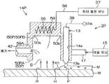
도 3A 는, 건조 헤드 (14) 의 모식적인 종단면도이며, 도 3B 는, 도 3A 의 IIIb-IIIb 선을 따른 횡단면도이다.FIG. 3A is a schematic longitudinal sectional view of the drying
건조 헤드 (14) 는, 예를 들어 블록상의 형태를 가지고 있다. 건조 헤드 (14) 는, 수평 방향으로 길이 방향을 가지고 있고, 길이 방향의 크기가 90 mm 정도이다. 건조 헤드 (14) 는, 기판 (W) 의 상면에 대향하고, 기판 (W) 보다 평면에서 보아 사이즈가 작은 대향면 (50) 을 갖는다. 대향면 (50) 은, 기판 (W) 의 상면으로부터 상방으로 함몰되고, 불활성 가스 저류 공간 (51) 을 건조 헤드 (14) 내에 형성하고 있다. 대향면 (50) 은, 건조 헤드 (14) 의 하면에 의해 구성된 제 1 면 (50A) 과, 불활성 가스 저류 공간 (51) 의 천정면에 의해 구성된 제 2 면 (50B) 을 포함한다.The drying
건조 헤드 (14) 는, 불활성 가스 저류 공간 (51) 을 배기하는 배기구 (52) 와, 불활성 가스 저류 공간 (51) 의 천정면에 형성된 복수의 불활성 가스 도입구 (53) 와, 복수의 불활성 가스 도입구 (53) 에 대해 불활성 가스 저류 공간 (51) 과는 반대측에 구획된 불활성 가스 공급실 (54) 을 포함한다.The drying
배기구 (52) 에는, 전술한 배기관 (42) 이 연결되어 있다. 배기구 (52) 로부터 배출된 유기 용제나 불활성 가스 등의 기체는, 배기관 (42) 을 통하여 건조 헤드 (14) 의 외부로 보내진다. 불활성 가스 공급실 (54) 에는, 전술한 제 3 불활성 가스 공급관 (40) 이 연결되어 있다.The above-described
제 3 불활성 가스 공급관 (40) 으로부터 불활성 가스 공급실 (54) 에 공급된 불활성 가스는, 불활성 가스 공급실 (54) 내에서 확산되고, 복수의 불활성 가스 도입구 (53) 로부터 균일한 유량으로 불활성 가스 저류 공간 (51) 에 공급된다. 이 실시 형태에서는, 배기구 (52) 에 의한 불활성 가스 저류 공간 (51) 의 배기와, 불활성 가스 저류 공간 (51) 의 불활성 가스의 공급에 의해, 대향면 (50) 과 기판 (W) 의 상면의 사이의 공간의 유기 용제의 기체의 농도가 저감된다. 이로써, 대향면 (50) 과 기판 (W) 의 상면의 사이의 공간에 그 공간 외보다도 저습도인 저습도 공간 (B) 이 형성된다. 저습도 공간 (B) 은, 기판 (W) 의 상면의 유기 용제의 증발을 촉진하므로, 기판 (W) 의 상면의 유기 용제를 효율적으로 건조시킬 수 있다.The inert gas supplied from the third inert
이와 같이, 건조 헤드 (14) 는, 기판 (W) 의 상면을 건조시키는 건조 헤드의 일례이다. 따라서, 이동 유닛 (15) 은, 기판 (W) 의 상면을 따라 건조 헤드 (14) 를 이동시키는 건조 헤드 이동 유닛으로서 기능한다.Thus, the drying
대향면 (50) 의 제 2 면 (50B) 은, 대략 선형의 평면 형상을 가지고 있다. 상세하게는, 대향면 (50) 의 제 2 면 (50B) 이 형성하는 선형은, 유기 용제 노즐 (13) 이 삽입 통과된 관통공 (14a) 으로부터 먼 위치에 배치된 사북 (50a) 을 가지고 있다. 대향면 (50) 의 제 2 면 (50B) 이 형성하는 선형은, 사북 (50a) 보다 관통공 (14a) 에 가까운 위치에 배치된 호 (50b) 를 가지고 있다.The
불활성 가스 저류 공간 (51) 은, 대략 선형의 평면 형상을 가지고 있다. 그 선형의 사북을 구성하는 부분 (51a) 은, 배기구 (52) 와 연통되어 있다. 당해 선형의 호를 구성하는 부분 (51b) 은, 유기 용제 노즐 (13) 보다 배기구 (52) 측에 위치하고 있다. 배기구 (52) 의 근처에 불활성 가스 저류 공간 (51) 의 선형의 사북을 구성하는 부분 (51a) 을 배치함으로써, 불활성 가스 저류 공간 (51) 내의 유기 용제의 증기를 집합시켜 배기구 (52) 로 유도할 수 있다. 이로써, 불활성 가스 저류 공간 (51) 을 효율적으로 배기할 수 있다.The inert
도 4 는, 기판 처리 장치 (1) 의 주요부의 전기적 구성을 설명하기 위한 블록도이다. 컨트롤러 (3) 는, 마이크로 컴퓨터를 구비하고 있고, 소정의 제어 프로그램에 따라, 기판 처리 장치 (1) 에 구비된 제어 대상을 제어한다. 보다 구체적으로는, 컨트롤러 (3) 는, 프로세서 (CPU) (3A) 와, 제어 프로그램이 격납된 메모리 (3B) 를 포함하고, 프로세서 (3A) 가 제어 프로그램을 실행함으로써, 기판 처리를 위한 여러 가지 제어를 실행하도록 구성되어 있다. 특히, 컨트롤러 (3) 는, 반송 로봇 (IR, CR), 전동 모터 (23), 노즐 이동 유닛 (29), 이동 유닛 (15), 차단판 승강 유닛 (28), 히터 통전 기구 (48), 히터 승강 기구 (26), 밸브류 (31, 33, 36, 37, 39, 41, 44, 49) 등의 동작을 제어한다. 컨트롤러 (3) 는, 제 3 불활성 가스 밸브 (41) 및 배기 밸브 (49) 를 제어함으로써, 건조 헤드 (14) 를 제어한다.Fig. 4 is a block diagram for explaining an electrical configuration of the main part of the substrate processing apparatus 1. Fig. The
도 5 는, 기판 처리 장치 (1) 에 의한 기판 처리의 일례를 설명하기 위한 흐름도이며, 주로, 컨트롤러 (3) 가 동작 프로그램을 실행함으로써 실현되는 처리가 나타나 있다. 미처리 기판 (W) 은, 반송 로봇 (IR, CR) 에 의해 캐리어 (C) 로부터 처리 유닛 (2) 에 반입되어 스핀 척 (5) 에 넘겨진다 (S1). 이 후, 기판 (W) 은, 반송 로봇 (CR) 에 의해 반출될 때까지, 스핀 척 (5) 에 수평으로 유지된다 (기판 유지 공정).5 is a flowchart for explaining an example of the substrate processing by the substrate processing apparatus 1, and mainly shows the processing realized by the
반송 로봇 (CR) 이 처리 유닛 (2) 외로 퇴피한 후, 약액 처리 (S2) 가 개시된다. 약액 처리 공정에서는, 먼저, 불활성 가스의 공급이 개시된다. 구체적으로는, 컨트롤러 (3) 는, 제 1 불활성 가스 밸브 (44) 를 열어, 기판 (W) 의 상면을 향하여 불활성 가스 노즐 (11) 로부터 불활성 가스를 공급시킨다. 이 때의 불활성 가스의 유량은 소유량이다. 소유량이란, 예를 들어 3 리터/min 미만의 유량이다.After the transport robot CR is retracted to the outside of the
컨트롤러 (3) 는, 전동 모터 (23) 를 구동하여, 스핀 베이스 (21) 를 소정의 약액 회전 속도로 회전시킨다. 컨트롤러 (3) 는, 차단판 승강 유닛 (28) 을 제어하여, 차단판 (7) 을 상위치로 위치시킨다. 그 한편으로, 컨트롤러 (3) 는, 노즐 이동 유닛 (29) 을 제어하여, 이동 노즐 (12) 을 기판 (W) 의 상방의 약액 처리 위치에 배치한다. 약액 처리 위치는, 이동 노즐 (12) 로부터 토출되는 약액이 기판 (W) 의 상면의 회전 중심에 착액하는 위치여도 된다. 그리고, 컨트롤러 (3) 는, 약액 밸브 (36) 를 연다. 그것에 의해, 회전 상태의 기판 (W) 의 상면을 향하여, 이동 노즐 (12) 로부터 약액이 공급된다. 공급된 약액은 원심력에 의해 기판 (W) 의 상면 전체에 널리 퍼진다.The
일정 시간의 약액 처리 후, 기판 (W) 상의 약액을 DIW 로 치환함으로써, 기판 (W) 의 상면으로부터 약액을 배제하기 위한 DIW 린스 처리 (S3) 가 실행된다. 구체적으로는, 컨트롤러 (3) 는, 약액 밸브 (36) 를 닫고, 대신에, DIW 밸브 (33) 를 연다. 그것에 의해, 회전 상태의 기판 (W) 의 상면을 향하여 DIW 노즐 (10) 로부터 DIW 가 공급된다. 공급된 DIW 는 원심력에 의해 기판 (W) 의 상면 전체에 널리 퍼진다. 이 DIW 에 의해 기판 (W) 상의 약액이 씻겨진다. 이 동안에, 컨트롤러 (3) 는, 노즐 이동 유닛 (29) 을 제어하여, 이동 노즐 (12) 을 기판 (W) 의 상방으로부터 컵 (8) 의 측방으로 퇴피시킨다.After the chemical liquid treatment for a predetermined period of time, the DIW rinse treatment (S3) for removing the chemical liquid from the upper surface of the substrate W is performed by replacing the chemical liquid on the substrate W with DIW. Specifically, the
DIW 린스 처리에 있어서도, 불활성 가스 노즐 (11) 에 의한 불활성 가스의 공급과, 스핀 베이스 (21) 에 의한 기판 (W) 의 회전이 계속된다. DIW 린스 처리에 있어서도 불활성 가스는, 소유량으로 공급된다. 기판 (W) 은, 소정의 DIW 린스 회전 속도로 회전된다.In the DIW rinsing process, the supply of the inert gas by the
일정 시간의 DIW 린스 처리 후, 기판 (W) 상의 DIW 를, 물보다 표면 장력이 낮은 저표면 장력 액체인 유기 용제 (예를 들어 IPA) 로 치환하는 유기 용제 처리 (S4) 가 실행된다.After the DIW rinsing treatment for a predetermined period of time, an organic solvent treatment (S4) for replacing DIW on the substrate W with an organic solvent (for example, IPA) which is a low surface tension liquid having a surface tension lower than that of water is performed.
유기 용제 처리가 실행되는 동안, 기판 (W) 을 가열해도 된다. 구체적으로는, 컨트롤러 (3) 가, 히터 승강 기구 (26) 를 제어하여, 히터 기구 (6) 를 상위치로 위치시킨다. 그리고, 컨트롤러 (3) 는, 히터 통전 기구 (48) 를 제어하여, 히터 기구 (6) 에 통전시킨다. 이로써, 기판 (W) 이 가열된다. 기판 (W) 은, 반드시 히터 기구 (6) 에 의해 가열될 필요는 없다. 즉, 컨트롤러 (3) 가, 가열 유체 밸브 (31) 를 열어, 하면 노즐 (9) 로부터 가열 유체를 공급시킴으로써, 기판 (W) 이 가열되어도 된다.While the organic solvent treatment is being performed, the substrate W may be heated. More specifically, the
컨트롤러 (3) 는, 이동 유닛 (15) 을 제어하여, 기판 (W) 의 상방의 유기 용제 린스 위치로 유기 용제 노즐 (13) 을 이동시킨다. 유기 용제 린스 위치는, 유기 용제 노즐 (13) 의 토출구 (13a) 로부터 토출되는 유기 용제 (예를 들어 IPA) 가 기판 (W) 의 상면의 회전 중심에 착액하는 위치여도 된다.The
그리고, 컨트롤러 (3) 는, 차단판 승강 유닛 (28) 을 제어하여, 차단판 (7) 을 상위치와 하위치의 사이의 처리 위치에 위치시킨다. 처리 위치는, 유기 용제 노즐 (13) 및 건조 헤드 (14) 가 차단판 (7) 과 기판 (W) 의 사이에서 수평으로 이동할 수 있는 위치이다. 그리고, 컨트롤러 (3) 는, DIW 밸브 (33) 를 닫고, 유기 용제 밸브 (39) 를 연다. 그것에 의해, 회전 상태의 기판 (W) 의 상면을 향하여, 유기 용제 노즐 (13) 로부터 유기 용제가 공급된다. 공급된 유기 용제는, 원심력에 의해 기판 (W) 의 상면 전체에 널리 퍼져, 기판 (W) 상의 DIW 를 치환한다. 유기 용제에 의해 DIW 를 치환한 후, 기판 (W) 에 발수제를 공급하는 다른 노즐 (도시 생략) 을 사용하여 기판 (W) 의 상면에 발수제를 공급하고, 유기 용제를 발수제로 치환한 후, 발수제를 유기 용제에 의해 치환해도 된다.Then, the
유기 용제 처리에 있어서, 컨트롤러 (3) 는, 스핀 척 (5) 의 회전을 감속하고, 또한, 유기 용제의 공급을 정지한다. 그것에 의해, 기판 (W) 상에 유기 용제의 액막이 형성된다 (액막 형성 공정).In the organic solvent treatment, the
유기 용제 액막의 배제에 있어서, 컨트롤러 (3) 가 제 1 불활성 가스 밸브 (44) 를 제어함으로써, 기판 (W) 의 중앙 영역을 향하여 불활성 가스 노즐 (11) 로부터 불활성 가스가 분사된다 (불활성 가스 분사 공정).The inert gas is injected from the
이로써, 불활성 가스가 분사되는 위치, 즉, 기판 (W) 의 중앙 영역에 있어서, 유기 용제 액막이 불활성 가스에 의해 배제된다. 이로써, 유기 용제 액막의 중앙 영역에, 기판 (W) 의 표면을 노출시키는 개구가 형성된다 (개구 형성 공정). 이와 같이, 불활성 가스 노즐 (11) 은, 유기 용제 액막의 중앙 영역을 향하여 불활성 가스를 분사하는 불활성 가스 공급 유닛에 포함된다. 또, 불활성 가스 노즐 (11) 은, 유기 용제 액막의 중앙 영역에 개구를 형성하는 개구 형성 유닛에도 포함된다. 유기 용제 액막의 중앙 영역이란, 평면에서 보아 기판 (W) 의 상면의 중앙 영역과 겹치는 영역이다. 이 개구를 넓힘으로써, 기판 (W) 상의 유기 용제가 기판 (W) 외로 배출된다 (액막 배제 공정). 컨트롤러 (3) 는, 전동 모터 (23) 를 제어하여, 액막 배제 공정과 병행해서 기판 (W) 을 회전시킨다 (기판 회전 공정). 불활성 가스 분사 공정은, 액막 배제 공정이 완료될 때까지 계속된다.Thereby, in the position where the inert gas is injected, that is, in the central region of the substrate W, the organic solvent liquid film is excluded by the inert gas. Thus, an opening for exposing the surface of the substrate W is formed in the central region of the organic solvent liquid film (opening forming step). Thus, the
불활성 가스의 분사에 의해 유기 용제 액막에 부가되는 힘과, 기판 (W) 의 회전에 의한 원심력에 의해 개구가 넓어진다. 개구의 넓어짐에 의해, 기판 (W) 의 상면으로부터 유기 용제 액막이 배제된다. 개구의 넓어짐에 수반하여, 컨트롤러 (3) 는, 이동 유닛 (15) 을 제어하여, 유기 용제 노즐 (13) 및 건조 헤드 (14) 를 기판 (W) 의 둘레 가장자리로 향하여 이동시킨다. 그 때, 컨트롤러 (3) 는, 유기 용제 밸브 (39) 를 열어, 유기 용제 액막에 유기 용제 노즐 (13) 로부터 유기 용제를 공급시키면서, 제 3 불활성 가스 밸브 (41) 를 열어 유기 용제 액막이 배제되어 노출된 기판 (W) 의 상면에 불활성 가스를 공급시켜 기판 (W) 의 상면을 건조시킨다. 또, 컨트롤러 (3) 는, 배기 밸브 (49) 를 열어, 불활성 가스 저류 공간 (51) 을 배기한다.The opening is widened by the force added to the organic solvent liquid film by the injection of the inert gas and the centrifugal force due to the rotation of the substrate W. [ The organic solvent liquid film is excluded from the upper surface of the substrate W by the widening of the opening. The
그리고, 유기 용제 처리를 끝낸 후, 컨트롤러 (3) 는, 유기 용제 밸브 (39), 제 3 불활성 가스 밸브 (41) 및 배기 밸브 (49) 를 닫는다. 그 후, 컨트롤러 (3) 는, 이동 유닛 (15) 을 제어하여, 유기 용제 노즐 (13) 및 건조 헤드 (14) 를 홈 위치로 퇴피시킨다. 또, 컨트롤러 (3) 는, 제 1 불활성 가스 밸브 (44) 를 닫아 불활성 가스 노즐 (11) 로부터의 불활성 가스의 공급을 정지시킨다. 그리고, 컨트롤러 (3) 는, 전동 모터 (23) 를 제어하여, 기판 (W) 을 건조 회전 속도로 고속 회전시킨다. 그것에 의해, 기판 (W) 상의 액 성분을 원심력에 의해 털어내기 위한 건조 처리 (S5 : 스핀 드라이) 가 실시된다.Then, after completing the organic solvent treatment, the
스핀 드라이에서는, 컨트롤러 (3) 는, 전동 모터 (23) 를 제어하여, 기판 (W) 을 소정의 건조 회전 속도로 고속 회전시킨다. 건조 회전 속도는, 예를 들어 800 rpm 이다. 이로써, 기판 (W) 상의 액 성분을 원심력에 의해 털어낸다. 스핀 드라이는, 컨트롤러 (3) 가 차단판 승강 유닛 (28) 을 제어하여 차단판 (7) 을 하위치로 이동시킨 상태로 실시된다.In spin dry, the
그 후, 전동 모터 (23) 를 제어하여 스핀 척 (5) 의 회전을 정지시킨다. 그리고, 컨트롤러 (3) 는, 차단판 승강 유닛 (28) 을 제어하여 차단판 (7) 을 상위치로 퇴피시킨다. 그리고, 컨트롤러 (3) 는, 제 1 불활성 가스 밸브 (44) 를 닫아 불활성 가스 노즐 (11) 에 의한 불활성 가스의 공급을 정지시킨다.Thereafter, the rotation of the
그 후, 반송 로봇 (CR) 이, 처리 유닛 (2) 에 진입하여, 스핀 척 (5) 으로부터 처리 완료된 기판 (W) 을 건져 올려, 처리 유닛 (2) 외로 반출한다 (S6). 그 기판 (W) 은, 반송 로봇 (CR) 으로부터 반송 로봇 (IR) 으로 넘겨지고, 반송 로봇 (IR) 에 의해, 캐리어 (C) 에 수납된다.Thereafter, the transfer robot CR enters the
도 6 은, 유기 용제 처리 (도 5 의 S4) 의 상세를 설명하기 위한 타임 차트이다. 도 7A ∼ 도 7D 는, 유기 용제 처리 (도 5 의 S4) 의 모습을 설명하기 위한 처리 유닛 (2) 의 주요부의 도해적인 단면도이다.Fig. 6 is a time chart for explaining details of the organic solvent treatment (S4 in Fig. 5). 7A to 7D are diagrammatic sectional views of the main part of the
유기 용제 처리는, 유기 용제 린스 스텝 T1 과 액막 형성 스텝 T2 와 천공 스텝 T3 과 구멍 넓힘 스텝 T4 를 포함하고, 이들이 순서대로 실행된다. 도 6 에 있어서 「IPA 노즐 위치」 는, 유기 용제 노즐 (13) 의 위치를 나타내고, 「IPA 토출」 은, 유기 용제 노즐 (13) 로부터의 유기 용제의 토출 상황을 나타낸다.The organic solvent treatment includes an organic solvent rinsing step T1, a liquid film forming step T2, a boring step T3, and a hole expanding step T4, which are executed in order. 6, "IPA nozzle position" indicates the position of the organic
유기 용제 린스 스텝 T1 은, 기판 (W) 을 회전시키면서, 기판 (W) 의 상면에 저표면 장력 액체로서의 유기 용제를 공급하는 스텝 (저표면 장력 액체 공급 공정, 액막 형성 공정) 이다. 도 7A 에 나타내는 바와 같이, 기판 (W) 의 상면에 유기 용제 노즐 (13) 로부터 유기 용제 (예를 들어 IPA) 가 공급된다. 공급된 유기 용제는, 원심력을 받아 기판 (W) 의 상면의 중심 영역으로부터 둘레 가장자리로 향한다. 그 때문에, DIW 린스 처리 (도 5 의 S3) 로 기판 (W) 의 상면에 공급된 DIW (린스액) 가 모두 유기 용제로 치환된다.The organic solvent rinsing step T1 is a step (low surface tension liquid supply step, liquid film forming step) of supplying an organic solvent as a low surface tension liquid to the upper surface of the substrate W while rotating the substrate W. An organic solvent (for example, IPA) is supplied from the organic
유기 용제 린스 스텝 T1 에서는, 컨트롤러 (3) 는, 차단판 승강 유닛 (28) 을 제어하여 차단판 (7) 을 처리 위치에 위치시킨다. 기판 (W) 의 상면은, 처리 위치에 위치하는 차단판 (7) 에 의해 덮여 있다. 그 때문에, 차단판 (7) 과 기판 (W) 의 상면의 사이의 공간은 외부의 공간으로부터 차단되어 있다. 그 때문에, 처리 유닛 (2) 의 벽면으로부터 튀어오른 액적이나 분위기 중의 미스트 등이 기판 (W) 의 상면에 부착되는 것을 억제 또는 방지할 수 있다.In the organic solvent rinse step T1, the
또, 유기 용제 린스 스텝 T1 에서는, 불활성 가스 노즐 (11) 로부터의 소유량으로의 불활성 가스의 공급이 계속된다.In addition, in the organic solvent rinsing step T1, the supply of the inert gas from the
유기 용제 린스 스텝 T1 의 기간 중, 기판 (W) 은, 스핀 척 (5) 에 의해, 소정의 유기 용제 린스 처리 속도로 회전된다. 유기 용제 린스 처리 속도는, 예를 들어 300 rpm 이다. 유기 용제 노즐 (13) 은, 중심 위치에 배치된다. 중심 위치란, 기판 (W) 의 회전 축선 (A1) 상에서 기판 (W) 에 상방으로부터 대향하는 위치이다. 유기 용제 밸브 (39) 는 개방 상태로 된다. 따라서, 유기 용제 (예를 들어 IPA) 가 기판 (W) 의 상면의 회전 중심을 향하여 상방으로부터 공급된다. 이동 노즐 (12) 은, 컵 (8) 의 측방의 홈 위치로 퇴피하고 있다. 약액 밸브 (36) 및 제 2 불활성 가스 밸브 (37) 는 폐쇄 상태로 제어된다.During the organic solvent rinse step T1, the substrate W is rotated by the
액막 형성 스텝 T2 는, 도 7B 에 나타내는 바와 같이, 기판 (W) 의 회전을 감속시켜 기판 (W) 으로부터 비산하는 유기 용제의 양을 감소시킴으로써, 유기 용제의 액막 (M) 의 막두께를 성장시키는 스텝이다. 액막 형성 스텝 T2 에서는, 막두께가 큰 액막 (M) (예를 들어 막두께 1 mm) 이 기판 (W) 의 표면에 형성된다.7B, the film thickness of the liquid film M of the organic solvent is increased by decreasing the amount of the organic solvent scattering from the substrate W by reducing the rotation of the substrate W Step. In the liquid film forming step T2, a liquid film M (for example, a film thickness of 1 mm) having a large film thickness is formed on the surface of the substrate W.
기판 (W) 의 회전은, 이 예에서는, 유기 용제 린스 처리 속도로부터 단계적 또는 연속적으로 감속된다. 보다 구체적으로는, 기판 (W) 의 회전 속도는, 300 rpm 으로부터, 50 rpm 으로 감속되어 소정 시간 (예를 들어 10 초) 유지되고, 그 후, 10 rpm 으로 감속되어 소정 시간 (예를 들어 30 초) 유지된다. 액막 형성 스텝 T2 에서는, 도 6 에 있어서의 「기판 회전 속도」 이외의 조건에 대해서는, 유기 용제 린스 스텝 T1 과 동일한 조건으로 유지된다. 유기 용제 노즐 (13) 은, 중심 위치에 유지되고, 계속해서, 기판 (W) 의 상면의 회전 중심을 향하여 유기 용제를 공급한다. 유기 용제 노즐 (13) 로부터의 유기 용제의 공급이, 액막 형성 스텝 T2 가 끝날 때까지 계속됨으로써, 기판 (W) 의 상면이 이르는 곳에서 유기 용제가 상실되는 일이 없다.In this example, the rotation of the substrate W is decelerated stepwise or continuously from the organic solvent rinse processing speed. More specifically, the rotation speed of the substrate W is reduced from 300 rpm to 50 rpm to be maintained for a predetermined time (for example, 10 seconds), thereafter decelerated to 10 rpm, Sec). In the liquid film forming step T2, conditions other than the " substrate rotation speed " in Fig. 6 are maintained under the same conditions as in the organic solvent rinsing step T1. The organic
천공 스텝 T3 은, 도 7C 에 나타내는 바와 같이, 액막 (M) 의 중앙 영역에 작은 개구 (H) (예를 들어 직경 30 mm 정도) 를 엶으로써, 기판 (W) 의 상면의 중앙 영역을 노출시키는 스텝이다 (개구 형성 공정). 천공 스텝 T3 에서는, 불활성 가스 노즐 (11) 로부터 액막 (M) 의 중앙 영역을 향하여 수직으로 대유량 (예를 들어 3 리터/min) 으로 불활성 가스 (예를 들어 질소 가스) 가 분사됨으로써 액막 (M) 에 개구 (H) 가 형성된다 (불활성 가스 분사 공정).7C, a small opening H (for example, about 30 mm in diameter) is formed in the central region of the liquid film M to expose the central region of the upper surface of the substrate W (Opening forming step). In the puncturing step T3, an inert gas (for example, nitrogen gas) is injected at a large flow rate (for example, 3 liters / min) vertically toward the central region of the liquid film M from the
천공 스텝 T3 에서는, 반드시 불활성 가스 분사 공정이 실행될 필요는 없다. 예를 들어, 기판 (W) 을 가열함으로써, 중앙 영역의 유기 용제를 증발시키고, 그것에 따라, 액막 (M) 의 중앙 영역에 개구 (H) 를 형성시켜도 된다 (개구 형성 공정). 컨트롤러 (3) 가, 가열 유체 밸브 (31) 를 열어, 하면 노즐 (9) 로부터 기판 (W) 의 하면의 중앙 영역으로 가열 유체를 공급시킴으로써, 기판 (W) 이 가열된다. 이 때, 불활성 가스는 기판 (W) 에 분사되지 않아도 된다. 이와 같이, 하면 노즐 (9) 은, 액막 (M) 의 중앙 영역에 개구 (H) 를 형성하는 개구 형성 유닛으로서 기능하는 것이 가능하다. 또, 기판 (W) 의 상면에 대한 불활성 가스의 분사와, 가열 유체에 의한 기판 (W) 의 하면의 중앙 영역의 가열의 양방에 의해 액막 (M) 에 개구 (H) 가 형성되어도 된다.In the puncturing step T3, the inert gas injection step is not necessarily executed. For example, the substrate W may be heated to evaporate the organic solvent in the central region, thereby forming an opening H in the central region of the liquid film M (opening forming step). The
천공 스텝 T3 의 기간 중, 컨트롤러 (3) 는, 유기 용제 밸브 (39) 를 제어하여, 유기 용제 노즐 (13) 로부터의 유기 용제의 공급을 정지한다. 또, 천공 스텝 T3 의 기간 중, 차단판 (7) 은, 처리 위치에서 유지된다.During the period of the drilling step T3, the
천공 스텝 T3 의 기간 중, 컨트롤러 (3) 는, 이동 유닛 (15) 을 제어함으로써, 유기 용제 노즐 (13) 및 건조 헤드 (14) 를 천공 위치에 위치시킨다. 천공 위치는, 기판 (W) 의 중앙 영역으로부터 기판 (W) 의 둘레 가장자리측으로 약간 어긋난 위치이다. 유기 용제 노즐 (13) 및 건조 헤드 (14) 가 천공 위치에 위치함으로써, 불활성 가스 노즐 (11) 은, 유기 용제 노즐 (13) 및 건조 헤드 (14) 에 의해 저해되는 일 없이, 액막 (M) 의 중앙 영역에 불활성 가스를 공급할 수 있다. 도 7C 에서는, 불활성 가스 노즐 (11) 의 하방에 건조 헤드 (14) 가 위치하지만, 실제로는, 천공 위치는, 불활성 가스 노즐 (11) 로부터 불활성 가스가 분사되는 기판 (W) 의 상면의 중앙 영역을 피한 위치이다.During the period of the drilling step T3, the
천공 스텝 T3 에서는, 컨트롤러 (3) 는, 전동 모터 (23) 를 제어하여 스핀 베이스 (21) 의 회전을 서서히 가속시킨다. 구체적으로는, 스핀 베이스 (21) 의 회전은, 소정의 개구 형성 속도가 될 때까지 가속된다. 개구 형성 속도는, 예를 들어 30 rpm 이다. 개구 형성 속도는, 30 rpm 에 한정되지 않고, 10 rpm ∼ 50 rpm 의 범위에서 변경 가능하다.In the drilling step T3, the
구멍 넓힘 스텝 T4 는, 도 7D 에 나타내는 바와 같이, 기판 (W) 을 회전시킴으로써 액막 (M) 의 개구 (H) 를 넓힘으로써 기판 (W) 의 상면으로부터 액막 (M) 을 배제하는 스텝이다 (액막 배제 공정, 기판 회전 공정). 구멍 넓힘 스텝 T4 에서는, 기판 회전 공정은, 액막 배제 공정과 병행해서 실행된다. 즉, 기판 (W) 의 상면으로부터 액막 (M) 이 배제될 때까지의 동안, 기판 (W) 의 회전은 유지된다.The hole expanding step T4 is a step for removing the liquid film M from the upper surface of the substrate W by widening the opening H of the liquid film M by rotating the substrate W as shown in Fig.7D Exclusion process, substrate rotation process). In the hole expanding step T4, the substrate rotating process is executed in parallel with the liquid film removing process. That is, while the liquid film M is excluded from the upper surface of the substrate W, the rotation of the substrate W is maintained.
구멍 넓힘 스텝 T4 에서는, 컨트롤러 (3) 는, 전동 모터 (23) 를 제어하여, 스핀 베이스 (21) 의 회전이 소정의 액막 배제 속도가 될 때까지 서서히 감속시킨다 (회전 감속 공정). 액막 배제 속도는, 예를 들어 10 rpm 이다. 액막 배제 속도는, 10 rpm 에 한정되지 않고, 10 rpm ∼ 30 rpm 의 범위에서 변경 가능하다.At the hole widening step T4, the
구멍 넓힘 스텝 T4 에서는, 불활성 가스 노즐 (11) 에 의한 기판 (W) 의 중앙 영역에 대한 불활성 가스의 분사가 유지된다 (불활성 가스 분사 공정). 불활성 가스 노즐 (11) 에 의한 불활성 가스의 분사는, 기판 (W) 의 상면으로부터 액막 (M) 이 배제될 때까지의 동안, 즉 액막 배제 공정이 완료될 때까지 계속된다.At the hole expanding step T4, the injection of the inert gas to the central region of the substrate W by the
구멍 넓힘 스텝 T4 에서는, 컨트롤러 (3) 는, 유기 용제 밸브 (39) 를 제어하여, 유기 용제 노즐 (13) 로부터 기판 (W) 의 상면에 대한 유기 용제의 공급을 재개한다. 유기 용제 노즐 (13) 로부터 공급되는 유기 용제의 온도 (유기 용제 온도) 는, 실온보다 높은 것이 바람직하고, 예를 들어 50 ℃ 이다. 그 때, 컨트롤러 (3) 는, 유기 용제 노즐 (13) 로부터 공급되는 유기 용제의 착액점 (P) 을 개구 (H) 의 외측에 설정한다. 착액점 (P) 이란, 유기 용제 노즐 (13) 로부터 공급되는 유기 용제가 기판 (W) 의 상면에 착액하는 점을 말한다. 유기 용제 노즐 (13) 은, 회전 축선 (A1) 둘레로는 회전하지 않기 때문에, 착액점 (P) 은, 기판 (W) 이 회전함으로써 기판 회전 방향 S 의 상류측으로 상대 이동하고 있는 것이 된다. 개구 (H) 의 외측이란, 개구 (H) 의 둘레 가장자리 (H1) 에 대해 회전 축선 (A1) 과는 반대측을 말한다.At the hole widening step T4, the
구멍 넓힘 스텝 T4 에서는, 컨트롤러 (3) 는, 제 1 불활성 가스 밸브 (44) 를 열어, 건조 헤드 (14) 로부터 기판 (W) 에 대한 불활성 가스의 공급을 개시한다. 건조 헤드 (14) 로부터 공급되는 불활성 가스의 온도 (불활성 가스 온도) 는, 실온보다 높은 것이 바람직하고, 예를 들어 50 ℃ 이다. 동시에, 컨트롤러 (3) 는, 배기 밸브 (49) 를 열어, 불활성 가스 저류 공간 (51) 에 저류된 불활성 가스 및 유기 용제의 증기를 배기구 (52) 로부터 배출한다.At the hole widening step T4, the
구멍 넓힘 스텝 T4 에서는, 컨트롤러 (3) 는, 개구 (H) 의 내측에 건조 영역 (R) 을 설정한다. 건조 영역 (R) 이란, 개구 (H) 의 내측에 있어서 기판 (W) 의 상면을 건조시켜야 할 영역이다. 건조 영역 (R) 이란, 구체적으로는, 기판 (W) 의 상면에 있어서 건조 헤드 (14) 의 대향면 (50) 과 대향하는 영역이다. 요컨대, 평면에서 보아 건조 헤드 (14) 가 기판 (W) 의 외주보다 내측에 위치하면, 건조 헤드 (14) 의 대향면 (50) 은 건조 영역 (R) 에 대향한다. 건조 영역 (R) 은, 평면에서 보아 건조 헤드 (14) 의 대향면 (50) 의 제 2 면 (50B) 과 겹치고 있다. 건조 헤드 (14) 는, 회전 축선 (A1) 둘레로는 회전하지 않기 때문에, 건조 영역 (R) 은, 기판 (W) 이 회전함으로써 기판 회전 방향 S 의 상류측으로 상대 이동하고 있는 것이 된다. 개구 (H) 의 내측이란, 개구 (H) 의 둘레 가장자리 (H1) 보다 회전 축선 (A1) 측을 말한다.At the hole widening step T4, the
불활성 가스 도입구 (53) 로부터의 불활성 가스의 공급 유량과, 배기구 (52) 로부터의 기체의 배출 유량을 조정함으로써, 불활성 가스 저류 공간 (51) 내의 분위기의 제원 (예를 들어, 분위기 중의 유기 용제 가스의 농도) 이 제어된다. 이로써, 대향면 (50) 과 건조 영역 (R) 의 사이의 공간에 저습도 공간 (B) 이 형성된다. 이와 같이, 건조 영역 (R) 의 상방 분위기를 저습도로 함으로써, 액막 (M) 이 배제된 후에 건조 영역 (R) 에 남은 유기 용제가 증발하기 쉬워진다. 그 때문에, 기판 (W) 의 상면을 효율적으로 건조시킬 수 있다.The flow rate of the inert gas supplied from the
구멍 넓힘 스텝 T4 에서는, 컨트롤러 (3) 는, 이동 유닛 (15) 을 제어하여, 토출구 (13a) 로부터 유기 용제를 토출하고 있는 상태의 유기 용제 노즐 (13) 을 천공 위치로부터 외주 위치로 이동시킨다. 이로써, 개구 (H) 의 넓어짐에 추종하도록 착액점 (P) 을 이동시킨다 (착액점 이동 공정). 외주 위치란, 유기 용제 노즐 (13) 이 기판 (W) 의 둘레 가장자리와 대향하는 위치이다. 착액점 (P) 은, 개구 (H) 의 둘레 가장자리 (H1) 부근에서 개구 (H) 의 넓어짐에 추종하는 것이 바람직하다.At the hole widening step T4, the
구멍 넓힘 스텝 T4 에서는, 컨트롤러 (3) 는, 이동 유닛 (15) 을 제어하여, 건조 헤드 (14) 를 천공 위치로부터 외주 위치로 이동시킨다. 이로써, 개구 (H) 의 넓어짐에 추종하도록 대향면 (50) 및 건조 영역 (R) 을 이동시킨다 (건조 영역 이동 공정). 전술한 바와 같이, 건조 헤드 (14) 는, 유기 용제 노즐 (13) 과 공통의 이동 부재 (17) 에 의해 지지되어 있기 때문에, 유기 용제 노즐 (13) 의 이동에 추종한다.At the hole widening step T4, the
도 8A 는, 구멍 넓힘 스텝 T4 에 있어서의 착액점 (P) 및 건조 영역 (R) 의 이동 궤적을 모식적으로 나타낸 평면도이다. 도 8B 는, 도 8A 의 착액점 (P) 및 건조 영역 (R) 의 주변의 확대도이다. 도 8A 및 도 8B 그리고 후술하는 도 15 에서는, 명료화를 위해서, 유기 용제의 액막 (M), 착액점 (P) 및 건조 영역 (R) 에 사선이 쳐져 있다.Fig. 8A is a plan view schematically showing the movement locus of the pick-up point P and the dry region R in the hole widening step T4. Fig. 8B is an enlarged view of the periphery of the pick-up point P and the drying region R in Fig. 8A. In FIGS. 8A and 8B and FIG. 15 described later, diagonal lines are drawn in the liquid film M, the liquid pick-up point P and the drying region R of the organic solvent for clarification.
도 8A 에 나타내는 바와 같이, 건조 영역 (R) 은, 착액점 (P) 의 이동에 추종하도록, 착액점 (P) 의 이동 궤적 (도 8A 의 일점 쇄선 참조) 을 따라 이동한다 (도 8A 의 2 점 쇄선 참조). 건조 헤드 (14) 및 유기 용제 노즐 (13) 을 이동시킬 때, 건조 영역 (R) 은, 착액점 (P) 에 대해 기판 회전 방향 S 의 하류측에, 반보다 넓은 영역이 위치하도록 설정되어 있어도 된다.8A, the dry region R moves along the movement locus of the liquidus point P (see the one-dot chain line in Fig. 8A) so as to follow the movement of the liquidus point P Dot chain line). When the drying
또, 도 8A 의 확대도인 도 8B 를 참조하여, 평면에서 보아 제 2 면 (50B) 과 겹치는 영역인 건조 영역 (R) 은, 대향면 (50) 의 제 2 면 (50B) 과 마찬가지로, 대략 선형의 평면 형상을 가지고 있다. 건조 영역 (R) 이 형성하는 선형은, 착액점 (P) 으로부터 먼 위치에 사북 (Ra) 을 가지고 있다. 건조 영역 (R) 이 형성하는 선형은, 사북 (Ra) 보다 착액점 (P) 에 가까운 위치에 호 (Rb) 를 가지고 있다. 호 (Rb) 는, 반보다 넓은 영역이 사북 (Ra) 보다 기판 회전 방향 S 의 상류측에 배치되어 있다. 호 (Rb) 는, 사북 (Ra) 보다 기판 (W) 의 외측 (둘레 가장자리측) 에 위치하고 있다. 호 (Rb) 는, 기판 회전 방향 S 를 따라 배치되어 있다. 동일하게, 대향면 (50) 의 제 2 면 (50B) 의 선형의 사북 (50a) 은, 착액점 (P) 으로부터 멀리 배치되어 있다. 또, 제 2 면 (50B) 의 선형의 호 (50b) 는, 사북 (Ra) 보다 착액점 (P) 에 가깝게 배치되어 있고, 또한, 기판 회전 방향 S 를 따라 배치되어 있다. 설명의 편의 상, 건조 영역 (R) 의 사북 (Ra) 에는, 제 2 면 (50B) 의 사북을 나타내는 부호 (50a) 를 병기하고, 건조 영역 (R) 의 호 (Rb) 에는, 제 2 면 (50B) 의 호를 나타내는 부호 (50a) 를 병기한다.Referring to Fig. 8B, which is an enlarged view of Fig. 8A, the drying region R, which is an area overlapping with the
이 실시 형태에 의하면, 개구 (H) 의 내측에 설정된 건조 영역 (R) 에 대향하는 대향면 (50) 과 건조 영역 (R) 의 사이의 공간에는, 그 공간 외보다도 저습도인 저습도 공간 (B) 이 형성된다. 그 때문에, 건조 영역 (R) 의 유기 용제를 신속하게 증발시킬 수 있다.According to this embodiment, in the space between the facing
건조 영역 (R) 및 대향면 (50) 은, 개구 (H) 의 넓어짐에 추종한다. 그 때문에, 유기 용제의 액막 (M) 이 배제된 후에 기판 (W) 의 상면에 남은 유기 용제를 신속하게 증발시킬 수 있다. 게다가, 대향면 (50) 이 대향하는 건조 영역 (R) 은 비교적 넓기 때문에, 건조 헤드 (14) 로부터 공급되는 불활성 가스가 기판 (W) 의 상면에 국부적으로 큰 외력을 작용시키는 경우는 없다.The drying zone R and the
한편, 대향면 (50) 은, 기판 (W) 보다 평면에서 보아 사이즈가 작다. 그 때문에, 유기 용제 노즐 (13) 을 회피한 위치, 즉 기판 (W) 의 상면에 충분히 가까운 위치에 건조 헤드 (14) 를 배치하면서 대향면 (50) 을 이동시킬 수 있다. 이로써, 건조 영역 (R) 에 남은 유기 용제를 한층 신속하게 증발시킬 수 있다.On the other hand, the opposing
건조 영역 (R) 이 개구 (H) 의 내측에 설정되어 있고, 착액점 (P) 이 개구 (H) 의 외측에 설정되어 있다. 그 때문에, 기판 (W) 의 상면으로부터 액막 (M) 이 배제될 때까지의 동안, 액막 (M) 으로부터 유기 용제가 자연스럽게 증발하는 것을 억제하면서, 충분한 양의 유기 용제를 액막 (M) 에 공급할 수 있다. 그 때문에, 개구 (H) 의 넓어짐에 의해 액막 (M) 이 배제되기 전에, 국소적으로 액막 (M) 이 증발하여 액막 균열이 발생하는 것을 억제할 수 있다.The drying region R is set inside the opening H and the liquid filling point P is set outside the opening H. [ It is possible to supply a sufficient amount of the organic solvent to the liquid film M while suppressing the natural evaporation of the organic solvent from the liquid film M while the liquid film M is excluded from the upper surface of the substrate W have. Therefore, before the liquid film M is excluded by the widening of the opening H, the liquid film M can be prevented from locally evaporating and causing liquid film cracking to occur.
이와 같이 하여, 유기 용제를 기판 (W) 의 상면으로부터 양호하게 배제할 수 있다.In this manner, the organic solvent can be well removed from the upper surface of the substrate W.
또, 건조 영역 (R) 이 착액점 (P) 의 이동에 추종하도록 착액점 (P) 의 이동 궤적을 따라 이동한다. 그 때문에, 착액점 (P) 에 착액한 유기 용제가 자연스럽게 증발하기 전에, 유기 용제를 건조 헤드 (14) 에 의해 확실하게 증발시킬 수 있다.Further, the drying region R moves along the movement locus of the liquidus point P so as to follow the movement of the liquidus point P. Therefore, the organic solvent can be surely evaporated by the drying
또, 개구 형성 공정에 있어서, 불활성 가스 노즐 (11) 이, 액막 (M) 의 중앙 영역을 향하여 불활성 가스를 분사함으로써, 개구 (H) 를 효율적으로, 또한 확실하게 중앙 영역에 형성할 수 있다.In the opening forming process, the
또, 불활성 가스의 분사가, 액막 배제 공정이 완료될 때까지 계속된다. 이로써, 개구 (H) 의 넓어짐이 촉진되어 보다 한층 신속하게 유기 용제를 기판 (W) 외로 배제할 수 있다. 또한, 액막 배제 공정에서는, 차단판 (7) 이 처리 위치에 위치하고 있기 때문에, 기판 (W) 의 상방을 기판 (W) 의 중심으로부터 기판 (W) 의 둘레 가장자리를 향하는 기류를 형성할 수 있다. 이와 같은 기류가 형성됨으로써, 건조 헤드 (14) 로부터 공급되는 불활성 가스에 의해 액막 (M) 으로부터 유기 용제가 튀었다고 해도, 튄 유기 용제가 개구 (H) 의 내측에 떨어지는 것을 방지할 수 있다.Further, the injection of the inert gas continues until the liquid film removal process is completed. As a result, the widening of the opening H is promoted, and the organic solvent can be excluded from the substrate W more quickly. Since the blocking
또, 액막 배제 공정과 병행해서 기판 (W) 을 회전시키는 기판 회전 공정이 실행되므로, 기판 (W) 의 회전에 의해 발생하는 원심력에 의해 개구 (H) 의 넓어짐을 촉진할 수 있다. 이로써, 한층 신속하게 액막 (M) 을 기판 (W) 외로 배제할 수 있다.In addition, since the substrate rotation process for rotating the substrate W is performed in parallel with the liquid film removal process, the widening of the opening H can be promoted by the centrifugal force generated by the rotation of the substrate W. Thereby, the liquid film M can be excluded from the substrate W more quickly.
또, 기판 (W) 의 회전에 수반하여, 액막 (M) 의 개구 (H) 의 외측에서는 착액점 (P) 이 기판 (W) 을 주사하고, 개구 (H) 의 내측에서는 건조 영역 (R) 이 기판 (W) 을 주사한다. 그것에 의해, 기판 (W) 의 상면 전체에 대해 균일한 건조 처리를 실시할 수 있다.At the outside of the opening H of the liquid film M along with the rotation of the substrate W, the liquid W of the substrate W is scanned at the liquid-contact point P, and the dry region R is formed at the inside of the opening H. [ And the substrate W is scanned. Thus, a uniform drying process can be performed on the entire upper surface of the substrate W.
액막 배제 공정의 초기 단계에서는, 액막 (M) 의 개구 (H) 가 작기 때문에, 건조 영역 (R) 은, 기판 (W) 의 상면의 중앙 영역 부근에 위치하고 있다. 한편, 액막 배제 공정의 종기 단계에서는, 액막 (M) 의 개구 (H) 가 커져 있으므로, 건조 영역 (R) 은, 기판 (W) 의 상면의 둘레 가장자리 부근에 위치하고 있다.The dry region R is located in the vicinity of the central region of the upper surface of the substrate W because the opening H of the liquid film M is small in the initial stage of the liquid film elimination process. On the other hand, in the last stage of the liquid film elimination process, the opening region H of the liquid film M is large, and thus the dry region R is located near the periphery of the upper surface of the substrate W.
만일, 액막 배제 공정에 있어서의 기판 (W) 의 회전 속도를 일정하게 하면, 액막 배제 공정의 종기 단계에 있어서 단위 시간당 기판 회전 방향 S 에 건조 영역 (R) 이 기판 (W) 의 상면을 상대 이동하는 거리는, 액막 배제 공정의 초기 단계에 있어서 단위 시간당 기판 회전 방향 S 에 건조 영역 (R) 이 기판 (W) 의 상면을 상대 이동하는 거리보다 커진다. 그 때문에, 액막 배제 공정의 종기 단계에서는, 액막 배제 공정의 초기 단계와 비교해서, 단위 면적당 기판 상면 건조 시간, 즉 건조 헤드 (14) 의 대향면 (50) 에 대향하는 시간이 짧다.If the rotation speed of the substrate W in the liquid film removal process is kept constant, the drying region R moves relative to the upper surface of the substrate W in the rotation direction S of the substrate per unit time in the end stage of the liquid film removal process Is larger than the distance that the dry region R moves relative to the upper surface of the substrate W in the substrate rotation direction S per unit time in the initial stage of the liquid film removal process. Therefore, in the final stage of the liquid film elimination step, the substrate top surface drying time per unit area, that is, the time period opposed to the
기판 회전 공정에 있어서 기판 (W) 의 회전을 서서히 감속시킴으로써, 액막 배제 공정의 종기 단계에 있어서 단위 시간당 기판 회전 방향 S 로 건조 영역 (R) 이 상대 이동하는 거리를 작게 하고, 단위 면적당 기판 상면 건조 시간을 길게 할 수 있다. 이로써, 액막 배제 공정의 초기 단계와 종기 단계에서, 단위 면적당 기판 상면 건조 시간의 차를 저감할 수 있다. 따라서, 기판 (W) 의 상면의 건조 불균일을 저감할 수 있다.The distance by which the drying region R moves relative to the substrate rotation direction S per unit time in the final stage of the liquid film removal process is reduced and the substrate top surface drying per unit area is reduced by gradually reducing the rotation of the substrate W in the substrate rotation process, The time can be lengthened. This makes it possible to reduce the difference in drying time of the top surface of the substrate per unit area in the initial stage and the final stage of the liquid film elimination process. Therefore, drying unevenness on the upper surface of the substrate W can be reduced.
본 실시 형태와 같이 건조 헤드 (14) 가 불활성 가스 공급 헤드인 경우, 기판 회전 공정에 있어서 기판 (W) 의 회전을 서서히 감속시킴으로써, 액막 배제 공정의 초기 단계와 액막 배제 공정의 종기 단계에서, 단위 면적당 기판 (W) 의 상면에 불활성 가스가 분사되는 시간의 차를 저감할 수 있다.When the drying
또, 건조 영역 (R) 은, 착액점 (P) 에 대해 기판 회전 방향 S 의 하류측에 반보다 넓은 영역이 위치하도록 설정된다. 그 때문에, 착액점 (P) 에 착액된 유기 용제가 자연스럽게 증발하기 전에 한층 확실하게 증발시킬 수 있다.The dry region R is set so that a region larger than half of the dry region R is located on the downstream side of the substrate rotation direction S with respect to the liquidus point P. [ Therefore, the organic solvent immersed in the liquid-chemical point P can be more reliably evaporated before it naturally evaporates.
또, 대략 선형의 평면 형상을 갖는 건조 영역 (R) 에 있어서, 선형의 사북 (Ra) 이 착액점 (P) 으로부터 먼 위치에 배치되고, 선형의 호 (Rb) 가 착액점 (P) 의 근처에 또한 기판 회전 방향 S 를 따르도록 배치되어 있다. 이로써, 선형의 호 (Rb) 가 사북 (Ra) 보다 기판 (W) 의 둘레 가장자리측에 위치하므로, 기판 (W) 의 상면의 각 부가 건조 헤드 (14) 의 대향면 (50) 에 대향하는 시간, 즉 건조 시간의 차를 저감할 수 있다. 따라서, 기판 (W) 의 상면의 건조 불균일을 저감할 수 있다.In the dry region R having a substantially linear planar shape, the linear convex portion Ra is arranged at a position far from the liquid contact point P, and the linear arc Rb is located near the liquid contact point P As shown in FIG. Thus, since the linear arc Rb is located on the peripheral edge side of the substrate W, the linear arc Rb is positioned at the time when each part of the upper surface of the substrate W faces the
또, 착액점 이동 공정 및 건조 영역 이동 공정에 있어서, 유기 용제 노즐 (13) 과 건조 헤드 (14) 를 공통으로 지지하는 이동 부재 (17) 를 이동시킴으로써, 유기 용제 노즐 (13) 과 건조 헤드 (14) 의 사이의 거리가 일정하게 유지된다. 따라서, 기판 (W) 의 상면 전체를 균등한 조건으로 건조시킬 수 있으므로, 건조 불균일을 저감할 수 있다.It is also possible to move the organic
또, 건조 헤드 (14) 가 불활성 가스 공급 헤드이기 때문에, 저습도 공간 (B) 의 습도를 불활성 가스에 의해 저감시킬 수 있다. 이로써, 건조 영역 (R) 으로부터 유기 용제를 신속하게 증발시킬 수 있으므로, 기판 (W) 의 상면을 신속하게 건조시킬 수 있다.Further, since the drying
또, 대향면 (50) 이, 기판 (W) 의 상면으로부터 상방으로 함몰되어 불활성 가스 저류 공간 (51) 을 형성하고 있다. 불활성 가스 저류 공간 (51) 에는, 불활성 가스 도입구 (53) 로부터 공급된 불활성 가스가 저류된다. 그 때문에, 불활성 가스 저류 공간 (51) 에 저류된 불활성 가스에 의해 기판 (W) 의 상면에 남은 유기 용제를 증발시킬 수 있다. 따라서, 보다 한층 신속하게 유기 용제를 증발시킬 수 있다.The opposing
또, 배기구 (52) 가 불활성 가스 저류 공간 (51) 을 배기한다. 이로써, 기판 (W) 의 상면으로부터 증발하여 증기가 된 유기 용제가, 불활성 가스 저류 공간 (51) 을 통하여 저습도 공간 (B) 으로부터 배제된다. 이로써, 저습도 공간 (B) 을 보다 한층 저습도로 유지할 수 있으므로, 건조 영역 (R) 의 유기 용제를 보다 한층 신속하게 증발시킬 수 있다.Further, the
다음으로, 제 1 실시 형태의 변형예에 대해 설명한다.Next, a modified example of the first embodiment will be described.
도 9 는, 제 1 실시 형태의 제 1 변형예에 관련된 처리 유닛 (2P) 에 구비된 건조 헤드 (14P) 를 나타낸 모식적인 단면도이다. 도 9 및 후술하는 도 11 ∼ 도 15 에서는, 지금까지 설명한 부재와 동일한 부재에는 동일한 참조 부호를 부여하고, 그 설명을 생략한다.9 is a schematic cross-sectional view showing a drying
제 1 실시 형태의 제 1 변형예에 관련된 건조 헤드 (14P) 가 제 1 실시 형태에 관련된 건조 헤드 (14) (도 3A 및 도 3B 참조) 와 주로 상이한 점은, 건조 헤드 (14P) 가, 불활성 가스 도입구 (53) 및 불활성 가스 공급실 (54) 대신에, 기판 (W) 의 상면 (건조 영역 (R)) 을 가열하는 히터 유닛 (55) 을 포함하는 점이다.The drying
대향면 (50P) 은, 기판 (W) 의 상면으로부터 상방으로 함몰되고, 불활성 가스 저류 공간 (51) (도 3A 참조) 대신에 건조실 (59) 을 형성하고 있다. 대향면 (50P) 은, 건조 헤드 (14P) 의 하면에 의해 구성된 제 1 면 (50PA) 과, 건조실 (59) 의 천정면에 의해 구성된 제 2 면 (50PB) 을 포함한다. 대향면 (50P) 의 제 2 면 (50PB) 은, 대략 선형의 평면 형상을 가지고 있어도 된다. 대향면 (50P) 의 제 2 면 (50PB) 이 형성하는 선형은, 관통공 (14a) 으로부터 먼 위치에 배치된 선형의 사북 (50a) 을 가지고 있다. 대향면 (50P) 의 제 2 면 (50PB) 이 형성하는 선형은, 사북 (50a) 보다 관통공 (14a) 에 가까운 위치에 배치된 호 (50b) 를 가지고 있다. 제 2 면 (50PB) 은, 평면에서 보아 건조 영역 (R) 과 겹치고 있다. 건조 헤드 (14P) 는, 건조실 (59) 내를 배기하는 배기구 (59A) 를 포함한다. 배기구 (59A) 는, 배기관 (42) 에 연결되어 있다.The facing
히터 유닛 (55) 은, 예를 들어, 건조실 (59) 의 천정부에 배치되어 있다. 히터 유닛 (55) 의 하면은, 대향면 (50P) 의 제 2 면 (50PB) 의 일부를 구성하고 있어도 된다. 히터 유닛 (55) 은, 통전됨으로써 온도가 상승되는 저항체를 포함한다. 히터 유닛 (55) 에는, 급전선 (56) 에 의해 히터 통전 유닛 (57) 으로부터의 전력이 공급된다.The
이 구성에 의하면, 히터 유닛 (55) 에 의한 기판 (W) 의 가열에 의해 건조 영역 (R) 의 유기 용제의 증발을 한층 촉진할 수 있다.According to this configuration, evaporation of the organic solvent in the drying region R can be further promoted by heating the substrate W by the
도 10 은, 제 1 실시 형태의 제 2 변형예에 관련된 처리 유닛 (2U) 에 구비된 건조 헤드 (14U) 를 나타낸 모식적인 단면도이다. 제 2 변형예의 건조 헤드 (14U) 가 제 1 변형예의 건조 헤드 (14P) 와 주로 상이한 점은, 건조 헤드 (14U) 의 대향면 (50U) 이 함몰되어 있지 않고, 건조실 (59) (도 9 참조) 을 형성하고 있지 않는 점이다. 대향면 (50U) 은, 히터 유닛 (55U) 의 하면에 의해 구성되어 있다. 대향면 (50U) 은, 유기 용제 노즐 (13) 이 삽입 통과된 관통공 (14a) 보다 히터 유닛 (55U) 측에서 건조 영역 (R) 과 대향하는 대향 부분 (50UB) 을 포함한다.10 is a schematic cross-sectional view showing a drying
대향 부분 (50UB) 은, 대략 선형의 평면 형상을 가지고 있어도 된다. 대향 부분 (50UB) 이 형성하는 선형은, 관통공 (14a) 으로부터 먼 위치에 배치된 사북 (50a) 을 갖는다. 대향 부분 (50UB) 이 형성하는 선형은, 사북 (50a) 보다 관통공 (14a) 에 가까운 위치에 배치된 호 (50b) 를 가지고 있다. 대향 부분 (50UB) 은, 평면에서 보아 건조 영역 (R) 과 겹치고 있다. 이 구성에 의하면, 히터 유닛 (55U) 을 기판 (W) 의 상면보다 가까운 위치에 배치하여 기판 (W) 을 가열할 수 있고, 이로써 건조 영역 (R) 의 유기 용제의 증발을 한층 촉진할 수 있다.The opposing portion 50UB may have a substantially linear planar shape. The linear shape formed by the opposed portion 50UB has a
도 11 은, 제 1 실시 형태의 제 3 변형예에 관련된 처리 유닛 (2Q) 이 구비하는 건조 헤드 (14Q) 를 나타낸 도면이다. 건조 헤드 (14Q) 는, 제 1 실시 형태에서 나타낸 복수의 불활성 가스 도입구 (53) 와, 불활성 가스 공급실 (54) 을 포함하고, 또한, 제 1 변형예에서 나타낸 히터 유닛 (55) 을 포함하고 있다. 바꾸어 말하면, 건조 헤드 (14Q) 는, 히터 유닛 (55) 을 갖는 불활성 가스 헤드이다. 이 구성에 의하면, 불활성 가스 저류 공간 (51) 의 불활성 가스에 의한 저습도 공간 (B) 의 습도의 저감과, 히터 유닛 (55) 에 의한 가열에 의해, 건조 영역 (R) 의 유기 용제의 증발을 한층 촉진할 수 있다.11 is a diagram showing a drying
도 12 는, 제 1 실시 형태의 제 4 변형예에 관련된 처리 유닛 (2R) 에 구비된 건조 헤드 (14R) 를 나타낸 모식적인 단면도이다. 제 1 실시 형태의 제 4 변형예에 관련된 건조 헤드 (14R) 가 제 1 실시 형태에 관련된 건조 헤드 (14) (도 3A 및 도 3B 참조) 와 주로 상이한 점은, 건조 헤드 (14R) 가, 배기구 (52), 불활성 가스 도입구 (53) 및 불활성 가스 공급실 (54) 대신에, 대향면 (50) 과 기판 (W) 의 상면 (건조 영역 (R)) 의 사이의 공간을 배기하는 배기 유닛 (58) 을 포함하는 점이다.12 is a schematic cross-sectional view showing a drying
건조 헤드 (14R) 에는, 불활성 가스 저류 공간 (51) (도 3A 참조) 대신에 건조실 (59R) 이 형성되어 있다. 건조실 (59R) 은, 대향면 (50R) 이 기판 (W) 의 상면으로부터 상방으로 함몰됨으로써 형성되어 있다. 대향면 (50R) 은, 건조 헤드 (14R) 의 하면에 의해 구성된 제 1 면 (50RA) 과, 건조실 (59R) 의 천정면에 의해 구성된 제 2 면 (50RB) 을 포함한다. 대향면 (50R) 의 제 2 면 (50RB) 은, 대략 선형의 평면 형상을 가지고 있어도 된다. 대향면 (50R) 의 제 2 면 (50RB) 이 형성하는 선형은, 관통공 (14a) 으로부터 먼 위치에 배치된 사북 (50a) 을 가지고 있다. 대향면 (50R) 의 제 2 면 (50RB) 이 형성하는 선형은, 사북 (50a) 보다 관통공 (14a) 에 가까운 위치에 배치된 호 (50b) 를 가지고 있다. 제 2 면 (50RB) 은, 평면에서 보아 건조 영역 (R) 과 겹치고 있다.In the drying
건조 헤드 (14R) 는, 건조실 (59R) 내를 배기하는 배기구 (59RA) 를 포함한다. 배기구 (59RA) 는, 예를 들어, 제 2 면 (50RB) 에 형성되어 있다. 배기구 (59RA) 는, 배기관 (42) 에 연결되어 있다. 이 구성에 의하면, 대향면 (50R) 과 건조 영역 (R) 의 사이의 공간을 배기하는 배기 유닛 (58) 에 의해, 유기 용제의 증기를 저습도 공간 (B) 으로부터 배제할 수 있다. 따라서, 건조 영역 (R) 의 유기 용제를 한층 신속하게 증발시킬 수 있다.The drying
도 13 은, 제 1 실시 형태의 제 5 변형예에 관련된 처리 유닛 (2S) 에 구비된 건조 헤드 (14S) 를 나타낸 모식적인 단면도이다. 제 1 실시 형태의 제 5 변형예에 관련된 건조 헤드 (14S) 가 제 1 실시 형태에 관련된 건조 헤드 (14) (도 3A 및 도 3B 참조) 와 주로 상이한 점은, 대향면 (50S) 이, 기판 (W) 의 상면에 평행한 평탄면이며, 대향면 (50S) 에 복수의 불활성 가스 토출구 (60) 가 형성되어 있는 점이다.13 is a schematic cross-sectional view showing a drying
또, 건조 헤드 (14S) 는, 제 1 실시 형태에 관련된 건조 헤드 (14) 와는 상이하고, 배기구 (52), 불활성 가스 도입구 (53) 및 불활성 가스 공급실 (54) 을 포함하지 않고, 불활성 가스가 제 3 불활성 가스 공급관 (40) 으로부터 불활성 가스 저류 공간 (51) 에 직접 공급된다.The drying
대향면 (50S) 은, 건조 헤드 (14S) 의 하면에 의해 구성되어 있다. 대향면 (50S) 은, 유기 용제 노즐 (13) 이 삽입 통과된 관통공 (14a) 보다 불활성 가스 토출구 (60) 측에서 건조 영역 (R) 과 대향하는 대향 부분 (50SB) 을 포함한다.The opposite surface 50S is constituted by the lower surface of the drying
대향 부분 (50SB) 은, 대략 선형의 평면 형상을 가지고 있어도 된다. 대향 부분 (50SB) 이 형성하는 선형은, 관통공 (14a) 으로부터 먼 위치에 배치된 사북 (50a) 을 가지고 있다. 대향 부분 (50SB) 이 형성하는 선형은, 사북 (50a) 보다 관통공 (14a) 에 가까운 위치에 배치된 호 (50b) 를 가지고 있다. 대향 부분 (50SB) 은, 평면에서 보아 건조 영역 (R) 과 겹치고 있다.The opposing portion 50SB may have a substantially linear planar shape. The linear shape formed by the opposing portion 50SB has a
이 구성에 의하면, 기판 (W) 의 상면에 평행한 평탄면인 대향면 (50S) 에 복수의 불활성 가스 토출구 (60) 가 형성되어 있다. 복수의 불활성 가스 토출구 (60) 에 연통하는 불활성 가스 저류 공간 (51) 에는, 불활성 가스 도입구 (53) 로부터 불활성 가스가 공급된다. 그 때문에, 불활성 가스가 1 개의 토출구로부터 공급되는 경우와 비교해서, 넓은 범위에 균일하게 불활성 가스를 공급할 수 있기 때문에, 저습도 공간 (B) 의 습도의 불균일을 저감할 수 있다. 따라서, 건조 영역 (R) 의 유기 용제를 신속하게 증발시킬 수 있고, 또한, 기판 (W) 의 상면의 건조 불균일을 저감할 수 있다. 또, 불활성 가스 토출구 (60) 가 복수 있음으로써, 기판 (W) 의 상면에 공급되는 불활성 가스의 기세를 저감할 수 있다. 그 때문에, 기판 (W) 의 상면에 작용하는 국부적인 외력을 저감할 수 있다.According to this configuration, a plurality of inert
<제 2 실시 형태>≪ Second Embodiment >
도 14 는, 본 발명의 제 2 실시 형태에 관련된 기판 처리 장치 (1T) 에 구비된 처리 유닛 (2T) 의 구성예를 설명하기 위한 도해적인 단면도이다. 도 15 는, 구멍 넓힘 스텝 T4 (도 6 및 도 7D 참조) 에 있어서의 착액점 (P) 및 건조 영역 (R) 의 이동 궤적을 모식적으로 나타낸 평면도이다. 제 2 실시 형태에 관련된 처리 유닛 (2T) 이 제 1 실시 형태에 관련된 처리 유닛 (2) 과 주로 상이한 점은, 유기 용제 노즐 (13T) 과 건조 헤드 (14T) 의 각각이, 독립적으로 수평 방향 및 수직 방향으로 이동 가능한 점이다.Fig. 14 is a schematic sectional view for explaining a structural example of the
상세하게는, 처리 유닛 (2) 은, 건조 헤드 (14T) 를 지지하는 이동 부재 (17T) 와, 이동 부재 (17T) 를 이동시키는 이동 유닛 (15T) 과, 유기 용제 노즐 (13T) 을 지지하여 유기 용제 노즐 (13T) 을 수평 방향 및 수직 방향으로 이동시키는 유기 용제 노즐 이동 유닛 (18) 을 포함한다. 유기 용제 노즐 (13T) 은, 기판 (W) 의 상면에 저표면 장력 액체를 공급하는 저표면 장력 액체 노즐의 일례이다. 건조 헤드 (14T) 를 지지하는 이동 부재 (17T) 를 이동시키는 이동 유닛 (15T) 은, 기판 (W) 의 상면을 따라 건조 헤드 (14T) 를 이동시키는 건조 헤드 이동 유닛으로서 기능한다.Specifically, the
유기 용제 노즐 (13T) 은, 유기 용제 노즐 이동 유닛 (18) 에 의해 수평 방향으로 이동함으로써, 기판 (W) 의 상면의 회전 중심에 대향하는 위치와, 기판 (W) 의 상면에 대향하지 않는 홈 위치 (퇴피 위치) 의 사이에서 이동할 수 있다. 홈 위치는, 평면에서 보아, 스핀 베이스 (21) 의 외방의 위치이며, 보다 구체적으로는, 컵 (8) 의 외방의 위치여도 된다. 이동 노즐 (12) 은, 연직 방향으로의 이동에 의해, 기판 (W) 의 상면에 접근시키거나 기판 (W) 의 상면으로부터 상방으로 퇴피시키거나 할 수 있다. 유기 용제 노즐 이동 유닛 (18) 은, 예를 들어, 연직 방향을 따른 회동축과, 회동축에 결합되어 수평으로 연장되는 아암과, 아암을 구동하는 아암 구동 기구를 포함한다.The organic
건조 헤드 (14T) 는, 관통공 (14a) 이 형성되어 있지 않은 점을 제외하고는, 제 1 실시 형태의 건조 헤드 (14) (도 3A 및 도 3B 참조) 와 동일한 구성이다.The drying
제 2 실시 형태의 기판 처리 장치 (1T) 에 의한 기판 처리는, 건조 헤드 (14T) 를 이동시키기 위해서 컨트롤러 (3) 가 이동 유닛 (15T) 을 제어하고, 유기 용제 노즐 (13T) 을 이동시키기 위해서 컨트롤러 (3) 가 유기 용제 노즐 이동 유닛 (18) 을 제어하는 점 (도 4 참조) 을 제외하고 제 1 실시 형태의 기판 처리 장치 (1) 에 의한 기판 처리와 거의 동일하다.The substrate processing by the
유기 용제 노즐 (13T) 과 건조 헤드 (14T) 의 각각은, 독립적으로 수평 방향 및 수직 방향으로 이동 가능하기 때문에, 제 2 실시 형태의 구멍 넓힘 스텝 T4 에서는, 제 1 실시 형태와는 달리, 건조 영역 (R) 이 착액점 (P) 의 이동에 추종하지 않도록 건조 영역 (R) 을 이동시키는 것도 가능하다 (도 15 참조).Since each of the organic
즉, 컨트롤러 (3) 는, 유기 용제 노즐 이동 유닛 (18) 을 제어하여, 토출구 (13Ta) 로부터 유기 용제를 토출하고 있는 상태의 유기 용제 노즐 (13T) 을 천공 위치로부터 외주 위치로 이동시킴으로써, 개구 (H) 의 넓어짐에 추종하도록 착액점 (P) 을 이동시킨다 (착액점 이동 공정). 동시에, 컨트롤러 (3) 는, 이동 유닛 (15T) 을 제어하여, 건조 헤드 (14T) 를 천공 위치로부터 외주 위치로 이동시킴으로써, 대향면 (50) 및 건조 영역 (R) 이, 착액점 (P) 에는 추종하지 않고, 개구 (H) 의 넓어짐에 추종하도록 이동시킨다 (건조 영역 이동 공정).That is, the
한편, 제 1 실시 형태의 구멍 넓힘 스텝 T4 와 마찬가지로, 건조 영역 (R) 이 착액점 (P) 의 이동에 추종하도록, 착액점 (P) 의 이동 궤적을 따라 건조 영역 (R) 을 이동시키는 것도 가능하다 (도 8A 참조).On the other hand, similarly to the hole widening step T4 of the first embodiment, the drying region R is moved along the movement locus of the liquidus point P so that the drying region R follows the movement of the liquidus point P (See Fig. 8A).
제 2 실시 형태에 의하면, 제 1 실시 형태와 동일한 효과를 발휘한다.According to the second embodiment, the same effects as those of the first embodiment are exhibited.
또, 제 2 실시 형태에 있어서도, 제 1 실시 형태와 동일한 변형예를 적용할 수 있다.Also in the second embodiment, the same modification as that of the first embodiment can be applied.
이 발명은, 이상에서 설명한 실시 형태로 한정되는 것이 아니고, 추가로 다른 형태로 실시할 수 있다.The present invention is not limited to the embodiments described above, but can be implemented in other forms.
예를 들어, 제 1 실시 형태의 기판 처리에서는, 액막 배제 공정이 완료될 때까지 불활성 가스 분사 공정을 계속한다고 했지만, 반드시 그럴 필요는 없다. 즉, 불활성 가스 노즐 (11) 이 기판 (W) 의 중앙 영역을 향하여 불활성 가스를 분사함으로써 액막 (M) 에 개구 (H) 를 형성한 후는, 컨트롤러 (3) 가 제 1 불활성 가스 밸브 (44) 를 닫아 불활성 가스 노즐 (11) 로부터의 불활성 가스의 공급을 정지시켜도 된다.For example, in the substrate processing of the first embodiment, the inert gas injection process is continued until the liquid film removal process is completed, but this is not necessarily required. That is, after the
또, 제 1 실시 형태의 기판 처리에서는, 구멍 넓힘 스텝 T4 에 있어서, 기판 (W) 을 회전시킨다고 했지만, 반드시 기판 (W) 을 회전시킬 필요는 없다. 기판 (W) 을 회전시키는 것에 의한 원심력과, 하면 노즐 (9) 로부터의 온수의 공급에 의한 기판의 가열과, 불활성 가스 노즐 (11) 로부터의 불활성 가스의 공급에 의한 액막 (M) 의 압출과, 히터 기구 (6) 에 의한 기판 (W) 의 가열 중 어느 하나, 또는 이들의 조합에 의해 개구 (H) 를 넓히는 것이 가능하다.In the substrate processing of the first embodiment, the substrate W is rotated in the hole expanding step T4, but it is not necessarily required to rotate the substrate W. The centrifugal force by rotating the substrate W and the heating of the substrate by the supply of the hot water from the
또, 대향면 (50, 50P, 50R) 의 제 2 면 (50B, 50PB, 50RB) 과, 대향 부분 (50UB, 50SB) 은, 반드시 선형의 평면 형상을 가지고 있을 필요는 없고, 적절히 그 형상을 변경하는 것이 가능하다.The second surfaces 50B, 50PB, and 50RB of the opposing
또, 건조 영역 (R) 은, 착액점 (P) 에 대해 기판 회전 방향 S 의 하류측에 반보다 넓은 영역이 위치하도록 설정된다고 했지만, 반드시 그럴 필요는 없고, 건조 영역 (R) 이 착액점 (P) 에 대해 기판 회전 방향 S 의 상류측에 반보다 넓은 영역이 위치하도록 설정되는 경우도 있을 수 있다.The drying region R is set such that a region larger than half of the drying region R is located on the downstream side of the substrate rotation direction S with respect to the liquidus point P, P in the substrate rotating direction S may be set to be larger than half of the area on the upstream side of the substrate rotation direction S. [
또, 건조 헤드의 구성은, 건조 헤드 (14, 14P, 14U, 14Q, 14R, 14S, 14T) 에 한정되지 않고, 예를 들어, 건조 헤드 (14, 14P, 14Q) 가 배기구 (52) 를 포함하지 않는 구성이어도 된다.The construction of the drying head is not limited to the drying heads 14, 14P, 14U, 14Q, 14R, 14S, 14T. For example, the drying heads 14, 14P, 14Q include the
본 발명의 실시 형태에 대해 상세하게 설명해 왔지만, 이들은 본 발명의 기술적 내용을 분명히 하기 위해서 이용된 구체예에 불과하고, 본 발명은 이들의 구체예로 한정하여 해석되어야 하는 것이 아니고, 본 발명의 범위는 첨부된 청구의 범위에 의해서만 한정된다.It is to be understood that the present invention is not limited to or by these specific examples, and that the scope of the present invention should not be construed as limited to the specific examples thereof, Quot; is limited only by the appended claims.
이 출원은, 2016 년 3 월 8 일에 일본 특허청에 제출된 일본 특허출원 2016-044554호에 대응하고 있고, 이 출원의 전체 개시는 여기에 인용에 의해 삽입되는 것으로 한다.This application corresponds to Japanese Patent Application No. 2016-044554 filed with the Japanese Patent Office on Mar. 8, 2016, the entire disclosure of which is hereby incorporated by reference.
1 : 기판 처리 장치
1T : 기판 처리 장치
3 : 제어 유닛
9 : 하면 노즐 (개구 형성 유닛)
11 : 이동 노즐 (개구 형성 유닛, 불활성 가스 공급 유닛)
13 : 유기 용제 노즐 (저표면 장력 액체 노즐, 저표면 장력 액체 공급 유닛)
13T : 유기 용제 노즐 (저표면 장력 액체 노즐, 저표면 장력 액체 공급 유닛)
14 : 건조 헤드 (불활성 가스 헤드)
14P : 건조 헤드
14Q : 건조 헤드 (불활성 가스 헤드)
14R : 건조 헤드
14S : 건조 헤드 (불활성 가스 헤드)
14T : 건조 헤드 (불활성 가스 헤드)
14U : 건조 헤드
15 : 이동 유닛 (건조 헤드 이동 유닛)
15T : 이동 유닛 (건조 헤드 이동 유닛)
17 : 이동 부재
17T : 이동 부재
20 : 척 핀 (기판 유지 유닛)
21 : 스핀 베이스 (기판 유지 유닛)
22 : 회전축 (기판 회전 유닛)
23 : 전동 모터 (기판 회전 유닛)
50 : 대향면
50a : 사북
50b : 호
50P : 대향면
50Q : 대향면
50R : 대향면
50S : 대향면
50T : 대향면
50U : 대향면
51 : 불활성 가스 저류 공간
52 : 배기구
53 : 불활성 가스 도입구
55 : 히터 유닛
58 : 배기 유닛
60 : 불활성 가스 토출구
A1 : 회전 축선
B : 저습도 공간
H : 개구
M : 액막1: substrate processing apparatus
1T: substrate processing device
3: control unit
9: Lower nozzle (aperture forming unit)
11: Moving nozzle (opening forming unit, inert gas supplying unit)
13: Organic solvent nozzle (low surface tension liquid nozzle, low surface tension liquid supply unit)
13T: Organic solvent nozzle (low surface tension liquid nozzle, low surface tension liquid supply unit)
14: Drying head (inert gas head)
14P: Drying head
14Q: Drying head (inert gas head)
14R: Drying head
14S: Drying head (inert gas head)
14T: Drying head (inert gas head)
14U: Drying head
15: moving unit (drying head moving unit)
15T: Moving unit (drying head moving unit)
17:
17T: movable member
20: chuck pin (substrate holding unit)
21: spin base (substrate holding unit)
22: rotating shaft (substrate rotating unit)
23: Electric motor (substrate rotating unit)
50: facing face
50a: the north
50b: Arc
50P: facing face
50Q: facing face
50R: facing face
50S: facing face
50T: facing face
50U: facing face
51: Inert gas storage space
52: Exhaust
53: Inert gas inlet
55: heater unit
58: Exhaust unit
60: Inert gas outlet
A1: rotation axis
B: Low humidity space
H: opening
M: liquid film
Claims (29)
상기 수평으로 유지된 기판의 상면에, 물보다 표면 장력이 낮은 저표면 장력 액체의 액막을 형성하는 액막 형성 공정과,
상기 저표면 장력 액체의 액막의 중앙 영역에 개구를 형성하는 개구 형성 공정과,
상기 개구를 넓힘으로써, 상기 기판의 상면으로부터 상기 액막을 배제하는 액막 배제 공정과,
저표면 장력 액체를 공급하는 저표면 장력 액체 노즐로부터 상기 개구의 외측에 설정한 착액점을 향하여 저표면 장력 액체를 상기 액막에 공급하면서, 상기 개구의 넓어짐에 추종하도록 상기 착액점을 이동시키는 착액점 이동 공정과,
상기 개구의 내측에 설정된 건조 영역에, 상기 기판보다 평면에서 보아 사이즈가 작은 대향면을 갖는 건조 헤드의 상기 대향면을 대향시켜 상기 대향면과 상기 건조 영역의 사이의 공간에 그 공간 외보다도 저습도인 저습도 공간을 형성하면서, 상기 건조 영역 및 상기 대향면을 상기 개구의 넓어짐에 추종하도록 이동시키는 건조 영역 이동 공정을 포함하는, 기판 처리 방법.A substrate holding step of holding the substrate horizontally,
A liquid film forming step of forming on the upper surface of the horizontally held substrate a liquid film of a low surface tension liquid having a lower surface tension than water,
An opening forming step of forming an opening in a central region of the liquid film of the low surface tension liquid;
A liquid film removing step of removing the liquid film from the upper surface of the substrate by widening the opening,
A low surface tension liquid supplying a low surface tension liquid is supplied to the liquid film from a low surface tension liquid toward a set liquid point set outside the opening from the low nozzle surface liquid liquid nozzle, A moving process,
The drying head having opposed faces of a drying head having opposed faces smaller in size than the substrate and opposed to the drying regions set inside the openings so that a space between the opposed faces and the drying region has a lower humidity And a drying region moving step of moving the drying region and the opposed surface to follow the spreading of the opening while forming a phosphorus low humidity space.
상기 건조 영역 이동 공정은, 상기 착액점의 이동에 추종하도록, 상기 착액점의 이동 궤적을 따라 상기 건조 영역을 이동시키는 공정을 포함하는, 기판 처리 방법.The method according to claim 1,
Wherein the drying region moving step includes a step of moving the drying region along a movement locus of the liquid point so as to follow the movement of the liquid point.
상기 개구 형성 공정이, 상기 기판의 중앙 영역을 향하여 불활성 가스를 분사하는 불활성 가스 분사 공정을 포함하고,
상기 불활성 가스 분사 공정이, 상기 액막 배제 공정이 완료될 때까지 계속되는, 기판 처리 방법.3. The method according to claim 1 or 2,
Wherein the opening forming step includes an inert gas injection step of injecting an inert gas toward a central region of the substrate,
Wherein the inert gas injection step is continued until the liquid film elimination step is completed.
상기 액막 배제 공정과 병행해서 상기 기판을 회전시키는 기판 회전 공정을 추가로 포함하는, 기판 처리 방법.4. The method according to any one of claims 1 to 3,
And a substrate rotating step of rotating the substrate in parallel with the liquid film removing step.
상기 기판 회전 공정이, 상기 기판의 회전을 서서히 감속시키는 회전 감속 공정을 포함하는, 기판 처리 방법.5. The method of claim 4,
Wherein the substrate rotating step includes a rotation decelerating step of gradually decelerating the rotation of the substrate.
상기 건조 영역이, 상기 착액점에 대해 기판 회전 방향 하류측에 반보다 넓은 영역이 위치하도록 설정되는, 기판 처리 방법.The method according to claim 4 or 5,
Wherein the drying region is set so that an area larger than half of the drying region is located on the downstream side of the rotation direction of the substrate with respect to the liquid pick-up point.
상기 건조 영역이, 선형의 평면 형상을 가지고 있고, 상기 선형의 사북이 상기 착액점으로부터 먼 위치에 배치되고, 상기 선형의 호가 상기 착액점에 가깝게 또한 기판 회전 방향을 따르도록 배치되어 있는, 기판 처리 방법.7. The method according to any one of claims 4 to 6,
Wherein the drying region has a linear planar shape and the linear convex portion is disposed at a position far from the liquid fitting point and the linear arc is disposed so as to approach the liquid fitting point and along the substrate rotation direction, Way.
상기 저표면 장력 액체 노즐과 상기 건조 헤드가 공통의 이동 부재에 지지되어 있고,
상기 착액점 이동 공정 및 상기 건조 영역 이동 공정이, 상기 이동 부재를 이동시키는 공정을 포함하는, 기판 처리 방법.8. The method according to any one of claims 1 to 7,
Wherein the low surface tension liquid nozzle and the drying head are supported by a common moving member,
Wherein the liquid-immersion point moving step and the drying area moving step include a step of moving the moving member.
상기 건조 헤드가, 불활성 가스를 공급하는 불활성 가스 공급 헤드인, 기판 처리 방법.9. The method according to any one of claims 1 to 8,
Wherein the drying head is an inert gas supply head for supplying an inert gas.
상기 대향면이, 기판의 상면으로부터 상방으로 함몰되어 불활성 가스 저류 공간을 형성하고 있고, 상기 불활성 가스 공급 헤드가, 상기 불활성 가스 저류 공간에 불활성 가스를 공급하는 불활성 가스 도입구를 포함하는, 기판 처리 방법.10. The method of claim 9,
Wherein the inert gas supply head includes an inert gas inlet for supplying an inert gas to the inert gas storage space, wherein the inert gas supply head includes an inert gas inlet for depressurizing upward from the upper surface of the substrate to form an inert gas storage space, Way.
상기 불활성 가스 공급 헤드가, 상기 불활성 가스 저류 공간을 배기하는 배기구를 추가로 포함하는, 기판 처리 방법.11. The method of claim 10,
Wherein the inert gas supply head further comprises an exhaust port for exhausting the inert gas storage space.
상기 대향면이, 기판의 상면에 평행한 평탄면이며, 상기 대향면에 복수의 불활성 가스 토출구가 형성되어 있고,
상기 불활성 가스 공급 헤드가, 상기 복수의 불활성 가스 토출구에 연통하는 불활성 가스 저류 공간과, 상기 불활성 가스 저류 공간에 불활성 가스를 공급하는 불활성 가스 도입구를 포함하는, 기판 처리 방법.10. The method of claim 9,
Wherein the opposing surface is a flat surface parallel to the upper surface of the substrate, a plurality of inert gas ejection openings are formed in the opposing surface,
Wherein the inert gas supply head includes an inert gas storage space communicating with the plurality of inert gas discharge openings and an inert gas inlet for supplying an inert gas to the inert gas storage space.
상기 건조 헤드가, 상기 건조 영역을 가열하는 히터 유닛을 포함하는, 기판 처리 방법.13. The method according to any one of claims 1 to 12,
Wherein the drying head comprises a heater unit for heating the drying zone.
상기 건조 헤드가, 상기 대향면과 상기 건조 영역의 사이의 공간을 배기하는 배기 유닛을 포함하는, 기판 처리 방법.14. The method according to any one of claims 1 to 13,
Wherein the drying head includes an exhaust unit for exhausting a space between the opposed surface and the drying region.
상기 기판 유지 유닛에 유지된 기판의 상면에 물보다 표면 장력이 낮은 저표면 장력 액체를 공급하는 저표면 장력 액체 공급 유닛과,
상기 기판 유지 유닛에 유지된 기판의 상면에 형성되는 상기 저표면 장력 액체의 액막의 중앙 영역에 개구를 형성하는 개구 형성 유닛과,
상기 기판 유지 유닛에 유지된 기판의 상면에 대향하고, 기판보다 평면에서 보아 사이즈가 작은 대향면을 가지며, 상기 대향면과 기판의 상면의 사이의 공간에 그 공간 외보다도 저습도인 저습도 공간을 형성함으로써 기판의 상면을 건조시키는 건조 헤드와,
상기 기판 유지 유닛에 유지된 기판의 상면을 따라 상기 건조 헤드를 이동시키는 건조 헤드 이동 유닛을 포함하는, 기판 처리 장치.A substrate holding unit for holding the substrate horizontally,
A low surface tension liquid supply unit for supplying a low surface tension liquid having a lower surface tension than water to the upper surface of the substrate held by the substrate holding unit;
An opening forming unit forming an opening in a central region of the liquid film of the low surface tension liquid formed on the upper surface of the substrate held by the substrate holding unit;
A space between the opposing surface and the upper surface of the substrate has a low humidity space having a lower humidity than the space outside the substrate, the space having an opposite surface facing the upper surface of the substrate held by the substrate holding unit, A drying head for drying the upper surface of the substrate,
And a drying head moving unit for moving the drying head along an upper surface of the substrate held by the substrate holding unit.
상기 저표면 장력 액체 공급 유닛, 상기 개구 형성 유닛, 상기 건조 헤드 및 상기 건조 헤드 이동 유닛을 제어하는 컨트롤러를 추가로 포함하고,
상기 컨트롤러가, 상기 저표면 장력 액체 공급 유닛으로부터 기판의 상면에 저표면 장력 액체를 공급시키고, 상기 기판의 상면에 저표면 장력 액체의 액막을 형성하는 액막 형성 공정과, 상기 개구 형성 유닛에 의해 상기 액막의 중앙 영역에 개구를 형성하는 개구 형성 공정과, 상기 개구를 넓힘으로써 상기 기판의 상면으로부터 상기 액막을 배제하는 액막 배제 공정과, 상기 저표면 장력 액체 공급 유닛으로부터 공급되는 저표면 장력 액체의 착액점을 상기 개구의 외측에 설정하여 상기 개구의 넓어짐에 추종하도록 상기 착액점을 이동시키는 착액점 이동 공정과, 상기 개구의 내측에 설정한 건조 영역에 상기 건조 헤드의 상기 대향면을 대향시켜, 상기 개구의 넓어짐에 추종하도록 상기 건조 영역 및 상기 대향면을 이동시키는 건조 영역 이동 공정을 실행하도록 프로그램되어 있는, 기판 처리 장치.16. The method of claim 15,
Further comprising a controller for controlling the low surface tension liquid supply unit, the opening forming unit, the drying head, and the drying head moving unit,
A liquid film forming step of supplying a low surface tension liquid to the upper surface of the substrate from the low surface tension liquid supply unit and forming a liquid film of low surface tension liquid on the upper surface of the substrate; A liquid film removing step of removing the liquid film from the upper surface of the substrate by widening the opening to form an opening in a central region of the liquid film; A liquid-liquid point shifting step of setting the liquid point on the outside of the opening so as to follow the spreading of the opening; and a liquid-liquid-pouring step of bringing the liquid-pouring point into contact with the facing surface of the drying head, A drying region moving step of moving the drying region and the opposing face so as to follow the spreading of the opening And is programmed to execute.
상기 컨트롤러가, 상기 건조 영역 이동 공정에 있어서, 상기 착액점의 이동에 추종하도록, 상기 착액점의 이동 궤적을 따라 상기 건조 영역을 이동시키는 공정을 실행하도록 프로그램되어 있는, 기판 처리 장치.17. The method of claim 16,
Wherein the controller is programmed to execute a step of moving the drying region along a movement locus of the pickling point so as to follow the movement of the pickling point in the drying region moving step.
상기 개구 형성 유닛이, 상기 기판 유지 유닛에 유지된 기판의 중앙 영역을 향하여 불활성 가스를 분사하는 불활성 가스 공급 유닛을 포함하고,
상기 컨트롤러가, 상기 개구 형성 공정에 있어서, 상기 불활성 가스 공급 유닛으로부터 불활성 가스를 공급시키는 불활성 가스 분사 공정을 실행하고, 또한, 상기 액막 배제 공정이 완료될 때까지 상기 불활성 가스 분사 공정을 계속하도록 프로그램되어 있는, 기판 처리 장치.18. The method according to claim 16 or 17,
Wherein the opening forming unit includes an inert gas supplying unit that injects an inert gas toward a central region of the substrate held by the substrate holding unit,
The controller performs the inert gas injection step for supplying the inert gas from the inert gas supply unit in the opening forming step and further executes the inert gas injection step until the liquid film elimination step is completed, And the substrate processing apparatus.
상기 기판 유지 유닛에 유지된 기판을 연직 방향을 따른 소정의 회전 축선 둘레로 회전시키는 기판 회전 유닛을 추가로 포함하고,
상기 컨트롤러가, 상기 액막 배제 공정과 병행해서 상기 기판을 회전시키는 기판 회전 공정을 실행하도록 프로그램되어 있는, 기판 처리 장치.19. The method according to any one of claims 16 to 18,
Further comprising a substrate rotating unit for rotating the substrate held by the substrate holding unit about a predetermined rotation axis along a vertical direction,
Wherein the controller is programmed to execute a substrate rotation process for rotating the substrate in parallel with the liquid film removal process.
상기 컨트롤러가, 상기 기판 회전 공정에 있어서, 기판의 회전을 서서히 감속시키는 회전 감속 공정을 실행하도록 프로그램되어 있는, 기판 처리 장치.20. The method of claim 19,
Wherein the controller is programmed to execute a rotation deceleration process for gradually decelerating the rotation of the substrate in the substrate rotation process.
상기 컨트롤러는, 상기 착액점에 대해 기판 회전 방향 하류측에 반보다 넓은 영역이 위치하도록 상기 건조 영역을 설정하도록 프로그램되어 있는, 기판 처리 장치.21. The method according to claim 19 or 20,
Wherein the controller is programmed to set the drying region such that an area larger than half is located on the downstream side of the substrate rotation direction with respect to the liquid pick-up point.
상기 대향면이, 선형의 평면 형상을 가지고 있고, 상기 선형의 사북이 상기 착액점으로부터 먼 위치에 배치되고, 상기 착액점에 가깝게 또한 기판 회전 방향을 따르도록 배치되어 있는, 기판 처리 장치.22. The method according to any one of claims 19 to 21,
Wherein the opposing face has a linear planar shape and the linear convex portion is disposed at a position far from the liquid fitting point and is disposed so as to approach the liquid fitting point and along the rotational direction of the substrate.
상기 저표면 장력 액체 공급 유닛이, 상기 기판 유지 유닛에 유지된 기판의 상면을 향하여 저표면 장력 액체를 공급하는 저표면 장력 액체 노즐을 포함하고,
상기 저표면 장력 액체 노즐과 상기 건조 헤드를 공통으로 지지하고, 상기 저표면 장력 액체 노즐 및 상기 건조 헤드를 상기 기판의 상방에서 이동시키는 이동 부재를 추가로 포함하고,
상기 건조 헤드 이동 유닛이, 상기 이동 부재를 이동시키는, 기판 처리 장치.23. The method according to any one of claims 15 to 22,
Wherein the low surface tension liquid supply unit includes a low surface tension liquid nozzle for supplying a low surface tension liquid toward an upper surface of the substrate held by the substrate holding unit,
Further comprising a moving member for supporting the low surface tension liquid nozzle and the drying head in common and moving the low surface tension liquid nozzle and the drying head above the substrate,
And the drying head moving unit moves the moving member.
상기 건조 헤드가, 불활성 가스를 공급하는 불활성 가스 공급 헤드인, 기판 처리 장치.24. The method according to any one of claims 15 to 23,
Wherein the drying head is an inert gas supply head for supplying an inert gas.
상기 대향면이, 상기 기판 유지 유닛에 유지된 기판의 상면으로부터 상방으로 함몰되어 불활성 가스 저류 공간을 형성하고 있고, 상기 불활성 가스 공급 헤드가, 상기 불활성 가스 저류 공간에 불활성 가스를 공급하는 불활성 가스 도입구를 포함하는, 기판 처리 장치.25. The method of claim 24,
Wherein the inert gas supply head is provided with an inert gas inlet for supplying an inert gas to the inert gas storage space, wherein the inert gas supply head comprises: And a substrate.
상기 불활성 가스 공급 헤드가, 상기 불활성 가스 저류 공간을 배기하는 배기구를 추가로 포함하는, 기판 처리 장치.26. The method of claim 25,
Wherein the inert gas supply head further comprises an exhaust port for exhausting the inert gas storage space.
상기 대향면이, 기판의 상면에 평행한 평탄면이며, 상기 대향면에 복수의 불활성 가스 토출구가 형성되어 있고,
상기 불활성 가스 공급 헤드는, 상기 복수의 불활성 가스 토출구에 연통하는 불활성 가스 저류 공간과, 상기 불활성 가스 저류 공간에 불활성 가스를 공급하는 불활성 가스 도입구를 포함하는, 기판 처리 장치.25. The method of claim 24,
Wherein the opposing surface is a flat surface parallel to the upper surface of the substrate, a plurality of inert gas ejection openings are formed in the opposing surface,
Wherein the inert gas supply head includes an inert gas storage space communicating with the plurality of inert gas discharge openings and an inert gas inlet for supplying an inert gas to the inert gas storage space.
상기 건조 헤드가, 상기 기판 유지 유닛에 유지된 기판의 상면을 가열하는 히터 유닛을 포함하는, 기판 처리 장치.28. The method according to any one of claims 15 to 27,
Wherein the drying head includes a heater unit for heating an upper surface of the substrate held by the substrate holding unit.
상기 건조 헤드가, 상기 대향면과 상기 기판 유지 유닛에 유지된 기판의 상면의 사이의 공간을 배기하는 배기 유닛을 포함하는, 기판 처리 장치.28. The method according to any one of claims 15 to 27,
Wherein the drying head includes an exhaust unit for exhausting a space between the opposed surface and the upper surface of the substrate held by the substrate holding unit.
Applications Claiming Priority (3)
| Application Number | Priority Date | Filing Date | Title |
|---|---|---|---|
| JPJP-P-2016-044554 | 2016-03-08 | ||
| JP2016044554A JP6672023B2 (en) | 2016-03-08 | 2016-03-08 | Substrate processing method and substrate processing apparatus |
| PCT/JP2017/006881 WO2017154599A1 (en) | 2016-03-08 | 2017-02-23 | Substrate processing method and substrate processing device |
Publications (2)
| Publication Number | Publication Date |
|---|---|
| KR20180098656A true KR20180098656A (en) | 2018-09-04 |
| KR102118274B1 KR102118274B1 (en) | 2020-06-02 |
Family
ID=59789423
Family Applications (1)
| Application Number | Title | Priority Date | Filing Date |
|---|---|---|---|
| KR1020187021935A Active KR102118274B1 (en) | 2016-03-08 | 2017-02-23 | Substrate processing method and substrate processing apparatus |
Country Status (6)
| Country | Link |
|---|---|
| US (2) | US10964558B2 (en) |
| JP (1) | JP6672023B2 (en) |
| KR (1) | KR102118274B1 (en) |
| CN (1) | CN108604546B (en) |
| TW (1) | TWI687989B (en) |
| WO (1) | WO2017154599A1 (en) |
Families Citing this family (8)
| Publication number | Priority date | Publication date | Assignee | Title |
|---|---|---|---|---|
| JP6982433B2 (en) * | 2017-08-24 | 2021-12-17 | 株式会社Screenホールディングス | Board processing equipment |
| JP6982434B2 (en) * | 2017-08-24 | 2021-12-17 | 株式会社Screenホールディングス | Board processing equipment and board processing method |
| JP6982432B2 (en) * | 2017-08-24 | 2021-12-17 | 株式会社Screenホールディングス | Board processing equipment |
| JP7034634B2 (en) * | 2017-08-31 | 2022-03-14 | 株式会社Screenホールディングス | Board processing method and board processing equipment |
| JP2019054112A (en) * | 2017-09-15 | 2019-04-04 | 株式会社Screenホールディングス | Wafer drying method and wafer drying device |
| KR102267912B1 (en) * | 2019-05-14 | 2021-06-23 | 세메스 주식회사 | Method for treating a substrate and an apparatus for treating a substrate |
| JP2021048336A (en) * | 2019-09-20 | 2021-03-25 | 三菱電機株式会社 | Treatment liquid generation method, treatment liquid generation mechanism, semiconductor manufacturing equipment and semiconductor manufacturing method |
| CN113053728B (en) | 2019-12-27 | 2024-08-27 | 株式会社斯库林集团 | Substrate processing method and substrate processing device |
Citations (3)
| Publication number | Priority date | Publication date | Assignee | Title |
|---|---|---|---|---|
| KR20070062457A (en) * | 2005-06-23 | 2007-06-15 | 동경 엘렉트론 주식회사 | Substrate processing method and substrate processing apparatus |
| US20090205684A1 (en) | 2008-02-15 | 2009-08-20 | Tokyo Electron Limited | Substrate processing apparatus, substrate processing method, and storage medium |
| KR20150005490A (en) * | 2012-11-08 | 2015-01-14 | 가부시키가이샤 스크린 홀딩스 | Substrate treatment method and substrate treatment apparatus |
Family Cites Families (21)
| Publication number | Priority date | Publication date | Assignee | Title |
|---|---|---|---|---|
| AT407586B (en) * | 1997-05-23 | 2001-04-25 | Sez Semiconduct Equip Zubehoer | ARRANGEMENT FOR TREATING DISC-SHAPED OBJECTS, ESPECIALLY SILICON WAFERS |
| JP2007081311A (en) | 2005-09-16 | 2007-03-29 | Renesas Technology Corp | Single wafer cleaning apparatus and semiconductor device manufacturing method |
| TWI378502B (en) * | 2006-06-12 | 2012-12-01 | Semes Co Ltd | Method and apparatus for cleaning substrates |
| JP4762098B2 (en) * | 2006-09-28 | 2011-08-31 | 大日本スクリーン製造株式会社 | Substrate processing apparatus and substrate processing method |
| JP5019370B2 (en) | 2007-07-12 | 2012-09-05 | ルネサスエレクトロニクス株式会社 | Substrate cleaning method and cleaning apparatus |
| JP4988510B2 (en) | 2007-10-31 | 2012-08-01 | 大日本スクリーン製造株式会社 | Substrate processing apparatus and substrate processing method |
| JP5153296B2 (en) * | 2007-10-31 | 2013-02-27 | 大日本スクリーン製造株式会社 | Substrate processing apparatus and substrate processing method |
| JP5139844B2 (en) | 2008-03-04 | 2013-02-06 | 大日本スクリーン製造株式会社 | Substrate processing method and substrate processing apparatus |
| JP5122371B2 (en) | 2008-05-26 | 2013-01-16 | 東京エレクトロン株式会社 | Substrate processing apparatus, substrate processing method, program, and storage medium |
| US20110289795A1 (en) * | 2010-02-16 | 2011-12-01 | Tomoatsu Ishibashi | Substrate drying apparatus, substrate drying method and control program |
| JP5632860B2 (en) * | 2012-01-05 | 2014-11-26 | 東京エレクトロン株式会社 | Substrate cleaning method, substrate cleaning apparatus, and substrate cleaning storage medium |
| JP6017922B2 (en) | 2012-10-29 | 2016-11-02 | 東京エレクトロン株式会社 | Substrate drying method, liquid processing system, and storage medium |
| JP5486708B2 (en) * | 2013-02-28 | 2014-05-07 | 大日本スクリーン製造株式会社 | Substrate processing apparatus and substrate processing method |
| JP6224515B2 (en) * | 2013-06-07 | 2017-11-01 | 東京エレクトロン株式会社 | Substrate processing apparatus, substrate processing method, and computer-readable recording medium recording substrate processing program |
| JP5995881B2 (en) * | 2014-01-09 | 2016-09-21 | 東京エレクトロン株式会社 | Substrate cleaning method, substrate cleaning apparatus, and computer-readable recording medium |
| JP6386769B2 (en) * | 2014-04-16 | 2018-09-05 | 株式会社荏原製作所 | Substrate drying apparatus, control program, and substrate drying method |
| JP6118758B2 (en) * | 2014-05-01 | 2017-04-19 | 東京エレクトロン株式会社 | Substrate processing apparatus, substrate processing method, and computer-readable recording medium recording substrate processing program |
| JP6410694B2 (en) * | 2014-10-21 | 2018-10-24 | 東京エレクトロン株式会社 | Substrate liquid processing method, substrate liquid processing apparatus, and computer readable storage medium storing substrate liquid processing program |
| US20170084470A1 (en) * | 2015-09-18 | 2017-03-23 | Tokyo Electron Limited | Substrate processing apparatus and cleaning method of processing chamber |
| JP6588819B2 (en) * | 2015-12-24 | 2019-10-09 | 株式会社Screenホールディングス | Substrate processing apparatus and substrate processing method |
| JP2017157800A (en) * | 2016-03-04 | 2017-09-07 | 東京エレクトロン株式会社 | Liquid processing method, substrate processing apparatus, and storage medium |
-
2016
- 2016-03-08 JP JP2016044554A patent/JP6672023B2/en active Active
-
2017
- 2017-02-23 CN CN201780008426.3A patent/CN108604546B/en active Active
- 2017-02-23 WO PCT/JP2017/006881 patent/WO2017154599A1/en not_active Ceased
- 2017-02-23 US US16/072,017 patent/US10964558B2/en active Active
- 2017-02-23 KR KR1020187021935A patent/KR102118274B1/en active Active
- 2017-03-06 TW TW106107189A patent/TWI687989B/en active
-
2021
- 2021-01-29 US US17/161,745 patent/US11501985B2/en active Active
Patent Citations (3)
| Publication number | Priority date | Publication date | Assignee | Title |
|---|---|---|---|---|
| KR20070062457A (en) * | 2005-06-23 | 2007-06-15 | 동경 엘렉트론 주식회사 | Substrate processing method and substrate processing apparatus |
| US20090205684A1 (en) | 2008-02-15 | 2009-08-20 | Tokyo Electron Limited | Substrate processing apparatus, substrate processing method, and storage medium |
| KR20150005490A (en) * | 2012-11-08 | 2015-01-14 | 가부시키가이샤 스크린 홀딩스 | Substrate treatment method and substrate treatment apparatus |
Also Published As
| Publication number | Publication date |
|---|---|
| JP6672023B2 (en) | 2020-03-25 |
| TW201802919A (en) | 2018-01-16 |
| KR102118274B1 (en) | 2020-06-02 |
| TWI687989B (en) | 2020-03-11 |
| WO2017154599A1 (en) | 2017-09-14 |
| US11501985B2 (en) | 2022-11-15 |
| CN108604546B (en) | 2022-12-02 |
| US20190035652A1 (en) | 2019-01-31 |
| US10964558B2 (en) | 2021-03-30 |
| JP2017162916A (en) | 2017-09-14 |
| CN108604546A (en) | 2018-09-28 |
| US20210151334A1 (en) | 2021-05-20 |
Similar Documents
| Publication | Publication Date | Title |
|---|---|---|
| KR20180098656A (en) | Substrate processing method and substrate processing apparatus | |
| KR102101562B1 (en) | Substrate processing method and substrate processing appratus | |
| TWI646596B (en) | Substrate processing method and substrate processing apparatus | |
| JP6588819B2 (en) | Substrate processing apparatus and substrate processing method | |
| US10510528B2 (en) | Substrate processing method | |
| US10900127B2 (en) | Substrate processing method and substrate processing apparatus | |
| US8607807B2 (en) | Liquid treatment apparatus and method | |
| JP2017208435A (en) | Substrate processing apparatus and substrate processing method | |
| KR102271110B1 (en) | Substrate processing method and substrate processing apparatus | |
| US12334366B2 (en) | Substrate processing apparatus and substrate processing method | |
| CN108666237B (en) | Substrate processing method and substrate processing apparatus | |
| JP7713834B2 (en) | SUBSTRATE PROCESSING METHOD AND SUBSTRATE PROCESSING APPARATUS | |
| KR20180025256A (en) | Substrate processing method | |
| JP2009267145A (en) | Substrate treating device, and substrate treating method | |
| JP6817821B2 (en) | Substrate processing equipment and substrate processing method | |
| JP6771080B2 (en) | Substrate processing equipment and substrate processing method | |
| JP2024064787A (en) | Substrate processing apparatus and substrate processing method | |
| WO2024090475A1 (en) | Substrate treatment device, substrate treatment process, and chamber cleaning method |
Legal Events
| Date | Code | Title | Description |
|---|---|---|---|
| A201 | Request for examination | ||
| AMND | Amendment | ||
| P11-X000 | Amendment of application requested |
St.27 status event code: A-2-2-P10-P11-nap-X000 |
|
| P13-X000 | Application amended |
St.27 status event code: A-2-2-P10-P13-nap-X000 |
|
| PA0105 | International application |
St.27 status event code: A-0-1-A10-A15-nap-PA0105 |
|
| PA0201 | Request for examination |
St.27 status event code: A-1-2-D10-D11-exm-PA0201 |
|
| PG1501 | Laying open of application |
St.27 status event code: A-1-1-Q10-Q12-nap-PG1501 |
|
| E902 | Notification of reason for refusal | ||
| PE0902 | Notice of grounds for rejection |
St.27 status event code: A-1-2-D10-D21-exm-PE0902 |
|
| AMND | Amendment | ||
| P11-X000 | Amendment of application requested |
St.27 status event code: A-2-2-P10-P11-nap-X000 |
|
| P13-X000 | Application amended |
St.27 status event code: A-2-2-P10-P13-nap-X000 |
|
| E601 | Decision to refuse application | ||
| PE0601 | Decision on rejection of patent |
St.27 status event code: N-2-6-B10-B15-exm-PE0601 |
|
| X091 | Application refused [patent] | ||
| AMND | Amendment | ||
| E13-X000 | Pre-grant limitation requested |
St.27 status event code: A-2-3-E10-E13-lim-X000 |
|
| P11-X000 | Amendment of application requested |
St.27 status event code: A-2-2-P10-P11-nap-X000 |
|
| P13-X000 | Application amended |
St.27 status event code: A-2-2-P10-P13-nap-X000 |
|
| PX0901 | Re-examination |
St.27 status event code: A-2-3-E10-E12-rex-PX0901 |
|
| PX0701 | Decision of registration after re-examination |
St.27 status event code: A-3-4-F10-F13-rex-PX0701 |
|
| X701 | Decision to grant (after re-examination) | ||
| GRNT | Written decision to grant | ||
| PR0701 | Registration of establishment |
St.27 status event code: A-2-4-F10-F11-exm-PR0701 |
|
| PR1002 | Payment of registration fee |
St.27 status event code: A-2-2-U10-U12-oth-PR1002 Fee payment year number: 1 |
|
| PG1601 | Publication of registration |
St.27 status event code: A-4-4-Q10-Q13-nap-PG1601 |
|
| PR1001 | Payment of annual fee |
St.27 status event code: A-4-4-U10-U11-oth-PR1001 Fee payment year number: 4 |
|
| PR1001 | Payment of annual fee |
St.27 status event code: A-4-4-U10-U11-oth-PR1001 Fee payment year number: 5 |
|
| P22-X000 | Classification modified |
St.27 status event code: A-4-4-P10-P22-nap-X000 |
|
| PR1001 | Payment of annual fee |
St.27 status event code: A-4-4-U10-U11-oth-PR1001 Fee payment year number: 6 |
|
| U11 | Full renewal or maintenance fee paid |
Free format text: ST27 STATUS EVENT CODE: A-4-4-U10-U11-OTH-PR1001 (AS PROVIDED BY THE NATIONAL OFFICE) Year of fee payment: 6 |