KR20180098594A - Tailgate for vehicles - Google Patents
Tailgate for vehicles Download PDFInfo
- Publication number
- KR20180098594A KR20180098594A KR1020187021070A KR20187021070A KR20180098594A KR 20180098594 A KR20180098594 A KR 20180098594A KR 1020187021070 A KR1020187021070 A KR 1020187021070A KR 20187021070 A KR20187021070 A KR 20187021070A KR 20180098594 A KR20180098594 A KR 20180098594A
- Authority
- KR
- South Korea
- Prior art keywords
- wall
- panel
- outer panel
- tailgate
- vehicle
- Prior art date
- Legal status (The legal status is an assumption and is not a legal conclusion. Google has not performed a legal analysis and makes no representation as to the accuracy of the status listed.)
- Granted
Links
Images

Classifications
-
- B—PERFORMING OPERATIONS; TRANSPORTING
- B60—VEHICLES IN GENERAL
- B60J—WINDOWS, WINDSCREENS, NON-FIXED ROOFS, DOORS, OR SIMILAR DEVICES FOR VEHICLES; REMOVABLE EXTERNAL PROTECTIVE COVERINGS SPECIALLY ADAPTED FOR VEHICLES
- B60J5/00—Doors
- B60J5/10—Doors arranged at the vehicle rear
- B60J5/101—Doors arranged at the vehicle rear for non-load transporting vehicles, i.e. family cars including vans
- B60J5/107—Doors arranged at the vehicle rear for non-load transporting vehicles, i.e. family cars including vans constructional details, e.g. about door frame, panels, materials used, reinforcements
-
- B—PERFORMING OPERATIONS; TRANSPORTING
- B60—VEHICLES IN GENERAL
- B60J—WINDOWS, WINDSCREENS, NON-FIXED ROOFS, DOORS, OR SIMILAR DEVICES FOR VEHICLES; REMOVABLE EXTERNAL PROTECTIVE COVERINGS SPECIALLY ADAPTED FOR VEHICLES
- B60J10/00—Sealing arrangements
- B60J10/30—Sealing arrangements characterised by the fastening means
- B60J10/34—Sealing arrangements characterised by the fastening means using adhesives
-
- B—PERFORMING OPERATIONS; TRANSPORTING
- B60—VEHICLES IN GENERAL
- B60Q—ARRANGEMENT OF SIGNALLING OR LIGHTING DEVICES, THE MOUNTING OR SUPPORTING THEREOF OR CIRCUITS THEREFOR, FOR VEHICLES IN GENERAL
- B60Q1/00—Arrangement of optical signalling or lighting devices, the mounting or supporting thereof or circuits therefor
- B60Q1/26—Arrangement of optical signalling or lighting devices, the mounting or supporting thereof or circuits therefor the devices being primarily intended to indicate the vehicle, or parts thereof, or to give signals, to other traffic
- B60Q1/30—Arrangement of optical signalling or lighting devices, the mounting or supporting thereof or circuits therefor the devices being primarily intended to indicate the vehicle, or parts thereof, or to give signals, to other traffic for indicating rear of vehicle, e.g. by means of reflecting surfaces
-
- B—PERFORMING OPERATIONS; TRANSPORTING
- B60—VEHICLES IN GENERAL
- B60Q—ARRANGEMENT OF SIGNALLING OR LIGHTING DEVICES, THE MOUNTING OR SUPPORTING THEREOF OR CIRCUITS THEREFOR, FOR VEHICLES IN GENERAL
- B60Q1/00—Arrangement of optical signalling or lighting devices, the mounting or supporting thereof or circuits therefor
- B60Q1/26—Arrangement of optical signalling or lighting devices, the mounting or supporting thereof or circuits therefor the devices being primarily intended to indicate the vehicle, or parts thereof, or to give signals, to other traffic
- B60Q1/2619—Arrangement of optical signalling or lighting devices, the mounting or supporting thereof or circuits therefor the devices being primarily intended to indicate the vehicle, or parts thereof, or to give signals, to other traffic built in the vehicle body
- B60Q1/2638—Positioning the device housing by indexing means separate from the fastening means, e.g. pins, rails
-
- B—PERFORMING OPERATIONS; TRANSPORTING
- B60—VEHICLES IN GENERAL
- B60Y—INDEXING SCHEME RELATING TO ASPECTS CROSS-CUTTING VEHICLE TECHNOLOGY
- B60Y2410/00—Constructional features of vehicle sub-units
- B60Y2410/12—Production or manufacturing of vehicle parts
- B60Y2410/125—Bounded parts
Landscapes
- Engineering & Computer Science (AREA)
- Mechanical Engineering (AREA)
- Lighting Device Outwards From Vehicle And Optical Signal (AREA)
- Body Structure For Vehicles (AREA)
- Moulds For Moulding Plastics Or The Like (AREA)
Abstract
차량용 테일 게이트(12)는 내측 패널(1) 및 외측 패널(2)을 포함한다. 외측 패널은 외벽(21) 및 외벽(21)에 인접하고 광학 유닛을 수용하기 위한 하우징(14)의 경계를 정하도록 하는 모서리벽(22)을 포함한다. 외측 패널(2)은, 외측 패널(2)의 내면에 위치되고 모서리벽(22) 및 외벽(21) 사이에서 다리를 형성하며 외측 패널(2) 및 내측 패널(1) 사이에서 결합 계면의 일 부품으로의 역할을 하는 다리 벽(23)을 더 포함한다. 차량용 테일 게이트(12)용 외측 패널(2)을 성형하는 방법으로서, 외벽(21), 모서리벽(22) 및 다리 벽(23)에 의해 경계가 정해지되 자연적으로 탈형될 수 없는 중공(25)을 형성하도록 가동 슬라이더(6)는 주형에서 제작되어 이용된다.The vehicle tailgate 12 includes an inner panel 1 and an outer panel 2. The outer panel includes an outer wall 21 and an edge wall 22 adjacent to the outer wall 21 and for delimiting the housing 14 for receiving the optical unit. The outer panel 2 is located on the inner surface of the outer panel 2 and forms a bridge between the corner wall 22 and the outer wall 21 and forms a bridge between the outer panel 2 and the inner panel 1, And a leg wall 23 serving as a part. A method of forming an outer panel (2) for a tailgate (12) for a vehicle comprising the steps of forming a hollow (25) which is delimited by an outer wall (21), an edge wall (22) and a leg wall The movable slider 6 is manufactured and used in a mold.
Description
본 발명은 차량용 테일 게이트(tailgate)에 관한 것으로, 보다 상세하게는 보통 광학 유닛을 포함하는 플라스틱 테일 게이트에 관한 것이다.BACKGROUND OF THE
차량용 테일 게이트는 일반적으로 구조 부품으로서의 내측 패널 및 외관 스킨으로서의 외측 패널을 포함한다. 때로는, 차량용 테일 게이트는 후미등으로 명명되는 테일 게이트의 우측 및 좌측단에 배치되는 광학 유닛을 더 포함한다. The tailgate for a vehicle generally includes an inner panel as a structural part and an outer panel as an exterior skin. Sometimes, the vehicle tailgate further includes an optical unit disposed at the right and left ends of the tailgate, which is termed a taillight.
테일 게이트의 외관은 전체 차량의 외부에서 볼 수 있는 스타일의 형상에 따라 매우 달라지고, 거기에 결합되는 후미등의 외관 또한 마찬가지다. 따라서, 논의되는 차량용 테일 게이트에는 광학 유닛을 수용하는 하우징이 제공되며, 그 형상은 적어도 광학 유닛의 결합 및 고정 계면으로서 적용되어야 하고 또한 테일 게이트의 외부 스타일 형상을 실현하는 데 일관되어야 한다.The appearance of the tailgate is very different according to the shape of the style visible from the outside of the whole vehicle, and the appearance of the tailgate attached to it is also the same. Thus, the vehicle tailgate discussed is provided with a housing for receiving an optical unit, the shape of which must be applied at least as a coupling and a fixed interface of the optical unit, and also to be consistent in realizing the exterior styling of the tailgate.
심미적인 외관의 필요성에 부가하여, 내부의 공간이 전자 장비들을 포함하기에 차량용 테일 게이트 내부의 방수(또는 기밀)가 강하게 요구된다. 이를 위해, 도 1에서 도시되는 바와 같이, 하나 이상의 광학 하우징(14)의 경계를 정하고(delimit) 테일 게이트를 형성하는 내측 패널(1) 및 외측 패널(2) 사이에서 연속의 밀봉 유로(4)에 의해 테일 게이트의 방수를 보장하게 하는 기술이 알려져 있다. 주로 접착에 의해 이루어지는 이 밀봉 유로는, 일반적으로 외측 패널의 안쪽면에 인가되며 외측 패널과 내측 패널을 서로 결합시키기 위해 사용된다. 차량의 제품 질량의 구속 조건 때문에, 밀봉 유로를 형성하는 접착은 보통 로봇(3)에 의해 침적된다. 도 1a에서 도시되는 바와 같이, 정확한 밀봉 유로를 구비할 목적으로, 로봇(3)은 접착제를 안쪽면에 대해 수직인 각도(따라서 밀봉 유로 자체에 수직인 각도로)로 외측 패널(2)에 인가하여야 하는데, 필요에 따라 접착제 비드를 적용하기 위한 여러 가지 평행 이동이 가능하도록 외부 패널의 안쪽면을 따라서 이동하게 된다. 그 후, 외측 패널의 안쪽면에 접착제로 이루어진 밀봉 유로를 가지는 내측 및 외측 패널은, 테일 게이트의 주 결합 방향으로 서로 가압됨에 의해 함께 결합되어서, 접착제의 퍼짐을 방지하게 된다. 이 주 결합 방향은 차량용 테일 게이트의 전체적인 형태에 대해 수직인 방향이다. 도 1은 주 결합 방향을 점선(5)으로 도시하였지만, 점선(5)에 의해 지시된 방향은 설명적인 것이라는 점이 이해되어야 하고, 도 1은 차량용 테일 게이트의 예시적인 부분도이며, 단지 테일 게이트의 일 측에 위치한 하나의 예시적인 광학 하우징을 개략적으로 도시하고 있기 때문에, 단지 예로서 제시된 것이지 제한적이지는 않다.In addition to the need for an aesthetic appearance, there is a strong need for watertightness (or airtightness) inside the tailgate for a vehicle because the internal space includes electronic equipment. To this end, as shown in Fig. 1, a
하지만, 직각이거나 급격하거나 예각을 포함하는 광학 하우징 영역의 형상 및 주 결합 방향(main bonding direction) 때문에, 특히 광학 유닛 부근의 외측 패널의 안쪽면에 위치된 코너에서 단일 축 로봇이 접착제를 인가하는 것은 거의 불가능하다. 대안적으로, 보다 적은 도료 기구(applicator) 또는 다축(multi-axis)을 가지는 로봇을 이용하는 것은 모든 경우가 아닌 몇몇의 경우에 도움을 줄 수 있고, 접착제를 밀봉 유로에 인가하는 것을 허용할 수 있다. However, due to the shape and main bonding direction of the optical housing area, which is at right angles, sharp or acute angles, and in particular at the corners located on the inner side of the outer panel near the optical unit, It is almost impossible. Alternatively, the use of a robot with less applicator or multi-axis may be helpful in some cases, but not all cases, and may allow application of adhesive to the sealing flow path .
아울러, 외측 및 내측 패널에 의해 형성된 하우징의 상부 벽들 각각은 다음의 방식으로 지향된다(거의 평행이고, 또는 보다 안좋은 언더컷 위치에서, 주 결합 방향에 대해):In addition, each of the upper walls of the housing formed by the outer and inner panels is oriented in the following manner (in the substantially parallel, or worse undercut position, with respect to the main engagement direction):
- 처음에는 주 결합 방향을 따라서 하나의 패널을 다른 패널에 그들의 최종 조립 위치로 가져오는 동안 용이한 맞춤(fitting)을 허용하지 않는다;Does not allow easy fitting during the first bringing one panel to the other to the final assembly position along the main coupling direction;
- 그 후 외측 패널에 안쪽면의 일부에 인가된 접착제 비드(glue bead)에서 두 패널의 조립을 위해 적절한 압력을 인가하는 것은 어렵거나 불가능한데("적절한 압력"에 의해라는 것은 후미등 영역의 3D 형상에 상관없이 전체 밀봉 유로에 대해 거의 일정한 압력을 인가하는 것을 의미함), 이는 상기 압력이 이 국부적인 부분보다 다소 평면인 전체 테일 게이트의 외형/외주(contour/perimeter)의 나머지에 수직인 방향으로 주로 인가되기 때문이다.- It is then difficult or impossible to apply appropriate pressure for the assembly of the two panels in a glue bead applied to a part of the inner side of the outer panel (by "proper pressure" , Meaning that the pressure is applied in a direction perpendicular to the rest of the contour / perimeter of the entire tailgate, which is somewhat more flat than this localized portion This is because it is mainly applied.
두 패널들 사이에서 접착제 비드 상에 압력이 전혀 인가되지 않거나 불충분하게 인가된다면 이는 및 테일 게이트 내의 누수 및 불연속의 밀봉을 야기할 수 있다. If no pressure is applied or insufficiently applied on the adhesive bead between the two panels, this can cause leakage and discontinuous sealing in the tailgate and in the tailgate.
따라서, 본 발명은, 특히 광학 유닛 하우징 주변에서, 테일 게이트를 형성하는 패널의 결합 밀봉을 용이하고 효율적이게 하는 차량용 테일 게이트를 제공하고자 한다.SUMMARY OF THE INVENTION Accordingly, the present invention seeks to provide a tailgate for a vehicle which, in particular, around the optical unit housing, makes joining sealing of the panel forming the tailgate easy and efficient.
본 발명의 일 과제는, SUMMARY OF THE INVENTION [0006]
- 내측 패널,- Inner panel,
- 외벽(21) 및 상기 외벽(21)에 인접하고 광학 유닛을 수용하기 위한 하우징(14)의 경계를 정하는 모서리벽(22)을 포함하는 외측 패널을 포함하는 차량용 테일 게이트를 제공하는 것에 있으며,- an outer panel comprising an outer wall (21) and an edge wall (22) adjacent to the outer wall (21) and delimiting a housing (14) for receiving an optical unit,
외측 패널(2)은, 상기 외측 패널(2)의 내면에 위치되고 상기 모서리벽(22) 및 상기 외벽(21) 사이에서 다리를 형성하며 상기 외측 패널(2) 및 상기 내측 패널(1) 사이에서 결합 계면의 일 부분으로의 역할을 하는 다리 벽(23)을 더 포함한다. The
접근하기 어려운 중공을 덮기 위한 추가적인 면을 제공하는 상기 다리로 인해, 내측 패널에 결합되는 외측 패널의 안쪽면은 외측 패널을 내측 패널에 결합하기 위한 로봇 및 도료 기구에 의해 쉽게 접근 가능하게 되고, 더 이상 그 사이의 직각이거나 급격하거나 예각을 가지는 깊은 코너의 벽으로의 접착제의 인가가 필요하지 않게 된다. 더욱이, 주 결합 방향으로 서로에 대한 외측 및 내측 패널의 적절한 가압(위 참조)은 더욱 쉽고 보다 신뢰할만하다. 즉, 90° 와 같거나 작은, 즉 예각 또는 거의 직각을 가지는 형상의 코너에 의해 형성되는, 광학 하우징 주변에서 결합면이 겪는 문제를 피할 수 있다.Due to the legs providing an additional surface for covering the inaccessible hollow, the inner surface of the outer panel joined to the inner panel is easily accessible by the robot and painting mechanism for joining the outer panel to the inner panel, So that it is not necessary to apply the adhesive to the deep corners of the wall at right angles or sharp or sharp angles therebetween. Moreover, proper pressurization of the outer and inner panels relative to each other in the main coupling direction (see above) is easier and more reliable. That is, the problem encountered by the mating surface around the optical housing, which is formed by corners of a shape equal to or less than 90 degrees, i.e., an acute or nearly right-angled shape, can be avoided.
그러므로, 내측 및 외측 패널 사이의 결합 계면은 더 평평하고 부드러워질 수 있고, 다시 말하면, 완만한 경사면을 가지며, 깊이가 충분한 광학 하우징이 외측 패널 상에 여전히 형성될 수 있다는 점에서 유리하다. 이는 예를 들면 두 패널의 주 결합 방향으로 서로에 대한 적절한 가압 및 접착에 의한 결합을 위해 사용되는 로봇의 접근을 편하게 하는 것에 의해 두 패널의 조립 과정을 상당히 개선시키고, 그 사이에 차량용 테일 게이트의 매우 다양한 스타일을 가능하게 한다. 이러한 적용을 통해서, 내측 및 외측 패널의 결합되는 면은 주 결합 방향을 따라서 서로 모두 보다 잘 접촉될 것이다. 게다가, 밀봉 유로가 충분한 접착제로 이어지고 특히, 후미등(taillight) 영역에서 차량용 테일 게이트의 적절한 방수를 야기하는 것을 보장한다.It is therefore advantageous in that the coupling interface between the inner and outer panels can be flatter and smoother, that is to say that the optical housing with a gentle slope and a sufficient depth can still be formed on the outer panel. This significantly improves the assembly process of the two panels by, for example, facilitating access of the robots used for proper pressing and bonding by adhesives to each other in the main coupling direction of the two panels, It enables a wide variety of styles. Through this application, the mating surfaces of the inner and outer panels will all better contact each other along the main mating direction. In addition, it ensures that the sealing flow path leads to a sufficient adhesive, especially in the taillight region, resulting in adequate watertightness of the tailgate of the vehicle.
바람직하게는, 테일 게이트는 하나 이상의 이하의 특징들을 개별적으로 또는 결합으로 또한 포함할 수 있다. Preferably, the tailgate may also include one or more of the following features individually or in combination.
바람직하게는, 외측 패널의 내측면에 위치된 다리 벽은 광학 유닛을 수용하기 위한 하우징의 바닥 벽을 가지는 둔각을 형성한다. Preferably, the leg wall located on the inner side of the outer panel forms an obtuse angle with the bottom wall of the housing for receiving the optical unit.
바람직하게는, 외측 패널에 결합된 내측 패널은 외측 패널의 다리 벽 및 광학 유닛을 수용하기 위한 하우징의 바닥 벽에 의해 형성된 둔각과 거의 같은 둔각을 형성한다. 외측 패널의 둔각 및 내측 패널의 둔각은 다리 벽의 위치에 의해 결정되고 거의 180°까지 가능하다는 점이 주목되어야 한다. 둔각은 180°에 보다 가까울수록, 후미등 영역에서 외측 패널 및 내측 패널 사이의 결합 계면(bonding interface)은 보다 평평하게 된다. 따라서, 외측 패널 및 내측 패널을 적절히 가압하고 조립하는 것이 보다 쉬워지고 그들 사이의 결합은 보다 신뢰할만하다. Preferably, the inner panel coupled to the outer panel forms an obtuse angle substantially equal to an obtuse angle formed by the leg wall of the outer panel and the bottom wall of the housing for receiving the optical unit. It should be noted that the obtuse angle of the outer panel and the obtuse angle of the inner panel are determined by the position of the leg wall and can be up to nearly 180 degrees. The closer the obtuse angle is to 180 °, the more flat the bonding interface between the outer panel and the inner panel in the taillight area. Thus, it is easier to press and assemble the outer and inner panels properly and the coupling between them is more reliable.
광학 유닛을 수용하기 위한 하우징은 외측 패널의 안쪽면에 형성된 연속의 밀봉 유로의 주위 내부에 위치되는 것이 바람직한데: 이는 광학 유닛의 구성들 및 전기 와이어링을 두 패널 사이의 건조한 공간 내에 있게 하는 것을 확실하게 한다. 즉, 테일 게이트의 연속의 밀봉 유로는 광학 유닛을 수용하기 위한 하우징을 포함하고 따라서 보호하는 물이 새지 않는 지역(watertight zone)을 형성한다. The housing for accommodating the optical unit is preferably located inside the periphery of a continuous sealing passage formed on the inner surface of the outer panel: this makes it possible to arrange the arrangements of the optical unit and the electrical wiring in a dry space between the two panels Make sure. That is, the continuous sealing passage of the tail gate includes a housing for accommodating the optical unit and thus forms a watertight zone for protecting it.
외벽, 모서리벽 및 다리 벽은 중공의 경계를 정하는 것이 바람직하다. 따라서, 테일 게이트의 외측 패널은 그 자체로 중공을 형성한다는 점에서 상당히 혁신적이다. 중공의 형상은 요구되는 차량의 가시 외관 및 광학 유닛을 수용하는 하우징의 형상의 기능으로서 다양해질 수 있다. It is preferred that the outer wall, corner wall and leg wall define a hollow boundary. Thus, the outer panel of the tailgate is quite innovative in that it forms a hollow by itself. The shape of the hollow can be varied as a function of the visible appearance of the vehicle and the shape of the housing housing the optical unit.
외측 패널의 중공은 차량의 XZ 평면을 따라서 대략 삼각형의 가로(또는 측면) 단면을 가지는 공간을 형성하는 것이 바람직한데, 이로 인해 중공의 기계적인 저항력을 강화시킨다. 하지만, 테일 게이트의 디자인에 따라서 많은 다른 형상들이 가능하다. The hollow of the outer panel preferably forms a space having a transverse (or lateral) cross section of approximately triangular shape along the XZ plane of the vehicle, thereby enhancing the mechanical resistance of the hollow. However, many different shapes are possible depending on the design of the tailgate.
중공은 테일 게이트의 주된 측면에 바람직하게 배치된 단벽에 의해 일 단에서 닫혀지는 것이 바람직하다. 따라서, 내측 및 외측 패널 사이에서 물의 진입이 방지되고 또한 테일 게이트의 외부로부터 미적이지 않은 부분은 보이지 않는다.The hollow is preferably closed at one end by the end wall which is preferably disposed on the major side of the tailgate. Thus, water ingress is prevented between the inner and outer panels, and the non-aesthetic portion from the outside of the tail gate is not visible.
내측 패널의 외측 패널과의 조립은 접착 및 가압에 의해 구현되는 것이 바람직한데, 접착은 로봇에 의한 방수 접착인 것이 바람직하다. 유리하게는, 내측 패널 및 외측 패널 사이의 결합 계면은 보다 평평하고 부드러울 수 있기 때문에, 접착제를 인가하도록 사용되는 로봇은 외측 패널에서 안쪽면 전체를 따라서 진입하여 보다 쉽고 부드럽게 움직일 수 있다. 보다 작은 도료 기구 또는 다축을 가지는 로봇을 사용하는 것이 더 이상 필요하지 않기 때문에, 로봇의 선택에 있어서 보다 자유로움을 준다. 이로 인해, 접착제는 연속적이고 충분히 유리하게 도포될 수 있다. 게다가, 외측 패널 및 내측 패널 서로가 접근하여 맞게되는(fitted) 것이 보다 쉬워진다. 그 후, 두 패널을 주 결합 방향으로 서로 적절하게 가압하는 것이 가능해지고, 즉, 3D 형상인 후미등 영역의 복잡성에 상관없이 전체 밀봉 유로에 걸쳐서 거의 일정하게 주 결합 방향으로 외측 패널의 안쪽면에서 접착제 비드에 압력을 가할 수 있어서, 두 패널을 요구되는 그들 사이에서 분배된 충분한 접착력으로 결합시킨다. 따라서, 테일 게이트의 방수가 보장된다. It is preferable that the inner panel is assembled with the outer panel by adhesion and pressing, and the adhesion is preferably waterproof adhesion by a robot. Advantageously, since the joining interface between the inner panel and the outer panel can be more flat and smooth, robots used to apply adhesive can enter along the entire inner surface of the outer panel and move more easily and smoothly. Since it is no longer necessary to use a smaller paint mechanism or a robot with multiple axes, it is more flexible in the selection of robots. As a result, the adhesive can be applied continuously and sufficiently advantageously. In addition, it is easier to fit the outer panel and the inner panel to each other. Thereafter, the two panels can be appropriately pressed together in the main engaging direction, that is, regardless of the complexity of the 3D-shaped taillight area, The beads can be pressurized so that the two panels are bonded with a sufficient adhesive force distributed between them. Therefore, the watertightness of the tail gate is guaranteed.
다리 벽은 모서리벽 및 외벽 상에서 형성된 스타일링 선(styling line)의 안쪽면 사이에서 다리를 형성하는 것이 바람직하다. 즉, 다리 벽은 스타일링 선의 영역에서 외벽에 연결된다. 테일 게이트의 스타일링 선은 보통 예를 들면 면의 접힘으로 인하여 형성된 테일 게이트의 외부면 상에서 시각적인 단절(visual rupture) 또는 각을 형성하는 선으로 이해된다. 스타일링 선의 영역에서 다리 벽을 외벽으로 연결시킴에 의해, 다리 벽 및 외벽 사이의 접합으로 인한 차량용 테일 게이트의 면의 예를 들면, 수축 흔적들과 같은 몇몇 결함들이 외부에서 보이지 않고, 스타일링 선에 의해 음영 또는 마스킹 처리된다. 따라서, 다리 벽을 외벽이 각도 변화(보통 접혀짐에 의해)를 갖는 스타일링 선 뒤의 외벽에 접합시키는 것이 유리하고, 적어도 몇몇의 결함들이 차량의 외부로부터 쉽게 보이지 않을 수 있다. The leg walls preferably form bridges between the corner walls and the inner surface of the styling line formed on the outer wall. That is, the leg wall is connected to the outer wall in the region of the styling line. The styling line of the tailgate is usually understood as a line that forms a visual rupture or angle on the outer surface of the tailgate formed, for example, by the folding of the surface. By connecting the leg wall to the outer wall in the region of the styling line, some defects, such as shrinkage marks, of the face of the tailgate of the vehicle due to joining between the leg wall and the outer wall are not visible from the outside, Shaded or masked. It is therefore advantageous to join the leg wall to the outer wall behind the styling line with the outer wall having an angular variation (usually by folding), and at least some of the defects may not be readily visible from the outside of the vehicle.
본 발명의 다른 과제는, 전술한 어떠한 실시예에 따른 차량용 테일 게이트의 외측 패널을 주조하는 방법을 제공하는 것에 있는데, 가동 슬라이더가 제작되어 이용되어서 외벽, 모서리 벽 및 다리 벽에 의해 경계가 정해진 중공을 형성한다. 더 이상 다리 벽에 의해 덮여지는 자연적으로 탈형될 수 없는 이런 중공은 따라서 주조(mold)되기 쉽다. 이 가동 슬라이더는 사출 성형(injection molding)의 경우 수축 가능한 코어이다. Another object of the present invention is to provide a method of casting an outer panel of a tailgate for a vehicle according to any of the above-described embodiments, wherein a movable slider is fabricated and used to form a hollow cavity defined by an outer wall, . These hollows, which can no longer be naturally demoulded to be covered by the bridge walls, are therefore susceptible to mold. This movable slider is a shrinkable core in the case of injection molding.
얻어진 차량용 테일 게이트는 외측 패널 및 내측 패널의 조립 공정에서 방수 조건을 달성하기 위한 보다 자유로운 설계 및 제조 가능성을 허용하는 것으로 이해된다.The resulting vehicle tailgate is understood to allow more freedom in design and manufacturability to achieve watertight conditions in the assembly process of the outer and inner panels.
첨부 도면은 본 발명의 바람직한, 그러나 제한적이지 않은 예시적인 실시 예를 개략적으로 설명하기 위해 사용된다. 본 발명의 여러 장점들 및 특징들은 첨부 도면을 참조하여 이하의 상세한 설명에 의해 보다 잘 이해될 수 있을 것이다. 이들 도면에 도시된 모든 방향, 형상, 각도, 길이 및 두께를 포함하는 치수, 거리 등은 예시의 목적으로만 주어지며, 본 발명은 이들로 한정되지 않는다는 것이 이해되어야 한다. 첨부된 도면에서:
도 1은 종래의 차량용 테일 게이트를 성형하기 위한 내측 패널에 외측 패널을 조립하는 주요 단계를 개략적으로 도시하고;
도 2는 본 발명의 일 실시예에 의한 차량의 후방으로부터 보여지는 차량용 테일 게이트의 외부에서 보여지는 도면으로서, 차량의 XYZ 방향이 개략적으로 도시되고;
도 3은 도 2에서 원형 부분의 후미등 영역을 분해하여 도시한 측단면도(XZ 평면을 따라);
도 4는 도 2의 테일 게이트를 성형하기 위한 내측 패널에 외측 패널을 조립하는 주요 단계를 개략적으로 도시하고;
도 5는 도 2의 테일 게이트의 외측 패널을 주조할 때 가동 슬라이더의 인출을 보여주는, 내측 패널의 안쪽면으로부터 개략적으로 보여지는 사시도를 도시한다.BRIEF DESCRIPTION OF THE DRAWINGS The accompanying drawings are used to schematically illustrate preferred, but non-limiting, embodiments of the invention. Various advantages and features of the present invention may be better understood by the following detailed description with reference to the accompanying drawings. It should be understood that dimensions, distances, etc., including all orientations, shapes, angles, lengths, and thicknesses shown in these figures are for illustrative purposes only, and the invention is not limited thereto. In the accompanying drawings:
BRIEF DESCRIPTION OF THE DRAWINGS Figure 1 schematically illustrates the main steps of assembling an outer panel to an inner panel for molding a conventional tailgate for a vehicle;
Fig. 2 is a view seen from the outside of a tailgate for a vehicle viewed from the rear of the vehicle according to an embodiment of the present invention, in which the X, Y and Z directions of the vehicle are schematically shown;
Fig. 3 is a side cross-sectional view (along the XZ plane) shown as an exploded view of the rear portion of the circular portion in Fig. 2;
Figure 4 schematically shows the main steps of assembling the outer panel to the inner panel for forming the tailgate of Figure 2;
Fig. 5 shows a perspective view schematically seen from the inner side of the inner panel, showing the withdrawal of the movable slider when casting the outer panel of the tailgate of Fig. 2;
전술한 차량용 테일 게이트의 바람직한 실시예가 이제 첨부 도면을 참조하여 서술되는데, 유사한 기능을 갖는 유사한 구성들을 위해 동일 참조부호가 사용된다.Preferred embodiments of the above-described vehicle tailgate are now described with reference to the accompanying drawings, wherein like reference numerals are used for like structures having similar functions.
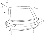
도 2는 일 실시예에 의한 차량용 테일 게이트(12)의 일 실시예를 개략적으로 보여준다. 차량용 테일 게이트는, 이 실시예의 테일 게이트의 양 측면에 대칭적으로 배치되는, 후미등(또는 리어 램프)을 수용하기 위한 광학 하우징(14)을 구비하도록 디자인된다. 차량들 사이에서 매우 다양화된 스타일의 결과, 테일 게이트에 위치된 광학 하우징(14)은 매우 다양한 형상일 수 있는데, 예를 들면, 하우징의 바닥 또는 테일 게이트(차량 외부에서 볼 수 있는)의 외부 표면과 예각 또는 거의 직각을 이루는 급경사의 벽을 갖도록 깊게 형성된다.2 schematically shows an embodiment of a
테일 게이트(12)는 내측 패널(1) 및 외측 패널(2)을 포함한다. 내측 패널(1)는 도 2에서 부분적으로 도시된다. 외측 패널(2)은 도 2에서 개략적으로 도시된다. 바람직하게는, 내측 패널(1)은 차량의 구조적인 부분인 반면, 외측 패널(2)은 외관 부분이다. 예를 들면, 내측 패널(1)은 열가소성 플라스틱(PP와 같은) 또는 열경화성 플라스틱(바람직하게는 SMC, 시트 몰딩 컴파운드(Sheet Molding Compound))로 이루어진 테일 게이트의 프레임이고 외측 패널(2)은 PP와 같은 열가소성 플라스틱 재질로 이루어진 테일 게이트의 외부 스킨이다. 내측 패널 및 외측 패널은 보통 복잡한 3-차원의 형상을 가지는데, 도면들에서 개략적으로 도시된 것에 반드시 제한되는 것은 아니다. The
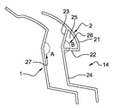
이하, 도 3 및 도 4를 참조한다. 외측 패널(2)은, 다른 구성들 중에서, 도 3에서 도시되는, 외벽(21) 및 모서리벽(22)을 포함한다. 모서리벽(22)은 외벽(21)에 인접하고 광학 유닛을 수용하기 위한 하우징(14)의 경계를 정하도록 한다. 외측 패널(2)은 하우징(14)의 바닥을 형성하는 바닥 벽(24)을 더 포함할 수 있는데, 바닥 벽(24)은 하우징(14)의 경계를 정하도록 한다. 도 3에서 보이지 않는 하우징의 다른 벽은 간결함을 위해 여기에서 설명되지 않는다. 이 실시예에서, 모서리벽(22)은 외벽(21)과 거의 직각을 이루고, 바닥 벽(24)은 모서리벽(22)과 거의 직각을 이룬다. 모서리벽(22)은 90°보다 다소 큰 바닥 벽(24)과 거의 직각을 형성한다고 볼 수 있어서, 패널의 탈형(demolding) 및 광학 유닛의 설치를 용이하게 하고 외벽(21)과 직각이거나 급격하거나 예각을 형성하게 한다.Reference is now made to Figs. 3 and 4. Fig. The
외측 패널(2)은 안쪽면에서, 상부 모서리벽(22) 및 외벽(21) 사이에서 그들 사이의 공간을 덮도록 디자인되는 다리 벽(23)을 더 포함한다. 다리 벽(23)은 내측 패널(1)의 면(A)에 결합되는 결합면(B)의 일부로서의 기능을 하고, 면(A 및 B)의 결합은 접착제에 의해 구현되는 것이 바람직하다. 접착제는 바람직하게는 두 패널들 사이의 공간을 건조한 생태로 유지하도록 밀봉하기 위해 이용되어서, 습기에 의해 영향을 받는 테일 게이트의 안쪽에서, 두 패널들 사이에 위치된 전기 와이어링 및 구성들을 보호한다. 보통, 접착제는, 주로 외측 패널(2)의 안쪽면에서 로봇(3, 도 4a에서 도시)에 의해 인가되어서, 이어지고 방수역할을 하는 접착제 비드(도 4b에서 도시)에 의해 형성되는 밀봉 유로(4, seal path)를 얻게 된다. 밀봉 유로는 자체로 폐루프를 형성하는 것이 바람직하다. The
도 3 및 4에서 보여지는 바와 같이, 다리 벽(23)은 모서리벽(22) 및 바닥 벽(24) 사이에서 거의 직각인 대신에, 바닥 벽(24)과 함께 둔각(26)을 형성한다. 아울러, 외측 패널(2)의 면(B)에 결합되는 내측 패널(1)의 면(A)은 바람직하게는 외측 패널(2)의 다리 벽(23) 및 바닥 벽(24)에 의해 형성되는 둔각(26)과 거의 같은 둔각(27)을 형성한다. 여기에서, 둔각(26 및 27)은 테일 게이트의 외부로부터 테일 게이트의 내부를 향해 보여진다. 외측 패널(2)의 둔각(26)이 다리 벽(23)의 위치에 의해 형성되고 거의 180°까지 가능할 수 있고 내측 패널(1)의 둔각(27) 또한 마찬가지이며, 다시 말해서 외측 패널(2)의 결합면(B) 및 외측 패널(2)의 결합면(B)에 결합되는 내측 패널(1)의 면(A)은 다리 벽(23)에 의해 후미등 영역에서 보다 평평해지는 점이 또한 주목된다. 두 둔각(26, 27)이 서로 완전히 동일하지 않게 하도록 작은 제조 공차가 주어질 수 있음이 이해되어야 한다. 3 and 4, the
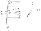
유리하게는, 외벽(21), 모서리벽(22) 및 다리 벽(23)은 중공(25)의 경계를 정한다. 차량의 XZ 평면을 따라서 중공(25)의 측단면을 형성하는 것이 도 3 및 4에서 도시된 예에 제한되는 것은 아니고, 하우징의 형상과 테일 게이트의 스타일의 기능에 따라서 달라질 수 있다. 또한, 도 5로부터 보여지는 바와 같이, 중공(25)은 바람직하게는 테일 게이트의 측면에 위치된 단벽(28)에 의해 하나 이상의 단에서 닫혀있어서, 내측 및 외측 패널 사이의 물의 유입이 방지된다. 따라서, 단벽(28)은 차량의 외부로부터 보여진다. Advantageously, the
후미등과 같은 광학 유닛이 하우징(14)에 설치될 때, 외측 패널(2)의 벽들(21, 22, 34 및 24) 사이에서, 외벽(21)은 차량의 외부로부터 보이는 벽일 뿐인 점이 또한 주목된다.It is also noted that, between the
일 실시예에 의하면, 다리 벽(23)은 모서리벽(22) 및 외벽(21)의 스타일링 선 사이에서 다리를 형성하고, 스타일링 선은 보통 외벽(21)의 접힘에 대응되는데, 테일 게이트의 외부면 상에서 시각적인 단절 또는 각을 형성하는 선을 만들어낸다. 특히, 다리 벽(23)의 외벽(21)으로의 접합은 차량용 테일 게이트(12)의 면에서의 수축 등과 같은 결함을 나타내는 것을 가능하게 한다. 따라서, 다리 벽(23)을 스타일링 선 뒤의 외벽(21)으로 접합시키도록 하는 것이 유리한데, 이로 인해 눈에 띄는 스타일링 선에 의해 어둡게 됨으로써 어떠한 결함이라도 차량의 외부로부터 잘 안보이게 된다. According to one embodiment the
도 4 및 도 5를 참조하여, 이제 차량용 테일 게이트의 제조 방법이 서술된다. 4 and 5, a method of manufacturing a tailgate for a vehicle will now be described.
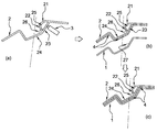
도 4는 전술한 차량용 테일 게이트를 제조를 위한 내측 및 외측 패널(1 및 2)을 조립의 주요 단계를 순차적으로 개략화하여 도시하는데(도면에서 점선은 전술한 두 패널의 주 결합 방향을 지시함):4 schematically shows the major steps of the assembly of the inner and
- 접착 로봇(3)에 의해 외측 패널(2)의 결합면(B, 안쪽면)에 접착제와 같은 결합 물질을 인가하고, 로봇(3)은 꽤 쉽고 부드럽게 결합면(B)으로 접근하여 결합면(B)을 따라서 이동할 수 있는데, 이는 결합면(B)이 더 가파른 경사를 제공하기 때문이다(도 4a); The
- 결합을 위한 연속의 밀봉 유로(4)가 적절히 형성될 때까지 로봇(3)은 외측 패널(2)의 결합면(B)을 따라서 다수 주행하도록 이동하고(도 4b);The
- 그 후, 테일 게이트 결합 방향 즉, 전술한 주 결합 방향으로 외측 패널(2) 및 내측 패널(1)에 충분한 압력으로 가압하여서, 두 패널을 그들 사이의 좋은 견고함으로 함께 결합한다(도 4c). - Then pressurize the
도 5로부터, 외측 패널(2)의 외벽(21), 모서리벽(22) 및 다리 벽(23)에 의해 경계가 정해지는 중공(25)을 형성하기 위해 주형(mold)에서 제작되어 이용되는, 가동 슬라이더(6)에 의해 외측 패널(2)을 주조하는 것으로 이루어진 본 발명의 실시예에 의한 차량용 테일 게이트의 제조 방법이 보여질 수 있다. 다리 벽(23) 없이, 모서리벽(22)과 외벽(21) 사이의 공간은 자연적으로 탈형 가능하다는(demoldable) 것이 주목된다. 이러한 체적은 다리 벽(23)에 의해 덮인 후에 자연적으로 탈형 가능할 수 없으므로 가동 슬라이더가 필요하다. 사출 성형을 위해, 가동 슬라이더는 수축 가능한 코어이다. 상기 슬라이더는 본 발명에 의한 단벽(28)에 의해 닫혀진 단에 반대편의 폐쇄되지 않은 다른 단을 통하여 쉽게 제거될 수 있다.5 shows an example of the
지금까지, 본 발명은 제한된 수의 실시 예에 의해 서술되었다. 그러나, 본 발명의 기본 원리로부터 벗어남이 없이, 첨부된 청구항에 의해 정의되는 본 발명의 범위를 벗어나지 않고, 단지 예로서 기술된 것에 관하여, 세부 사항들 및 실시 예들이 다양할 수도 있음이 이해되어야 한다.So far, the present invention has been described by a limited number of embodiments. It should be understood, however, that the details and embodiments may be varied with regard to what is described as an example only, without departing from the scope of the invention as defined by the appended claims, without departing from the underlying principles of the invention .
Claims (11)
외벽(21) 및 상기 외벽(21)에 인접하고 광학 유닛을 수용하기 위한 하우징(14)의 경계를 정하도록 하는 모서리벽(22)을 포함하는 외측 패널(2)을 포함하고,
상기 외측 패널(2)은, 상기 외측 패널(2)의 내면에 위치되고 상기 모서리벽(22) 및 상기 외벽(21) 사이에서 다리를 형성하며 상기 외측 패널(2) 및 상기 내측 패널(1) 사이에서 결합 계면의 일 부분으로의 역할을 하는 다리 벽(23)을 더 포함하는 것을 특징으로 하는 차량용 테일 게이트(12).
An inner panel (1); And
And an outer panel (2) comprising an outer wall (21) and an edge wall (22) adjacent the outer wall (21) and defining a housing (14) for receiving an optical unit,
Wherein the outer panel 2 is located on the inner surface of the outer panel 2 and forms a bridge between the corner wall 22 and the outer wall 21 and the outer panel 2 and the inner panel 1, Further comprising a leg wall (23) which acts as a part of the bonding interface between the legs (23).
상기 외측 패널(2)의 다리 벽(23)은 광학 유닛을 수용하기 위한 하우징(14)의 바닥 벽(24)을 가지는 둔각(26)을 형성하고, 상기 외측 패널(2)의 둔각(26)은 차량의 외부에서 보이는 것을 특징으로 하는 차량용 테일 게이트(12).
The method according to claim 1,
The leg wall 23 of the outer panel 2 defines an obtuse angle 26 having a bottom wall 24 of the housing 14 for receiving an optical unit and an obtuse angle 26 of the outer panel 2 Is seen from the outside of the vehicle.
상기 외측 패널(2)의 결합면(B)에 결합된 상기 내측 패널(1)의 일 면(A)은 상기 외측 패널(2)의 다리 벽(23) 및 상기 광학 유닛을 수용하기 위한 상기 하우징(14)의 바닥 벽(24)에 의해 형성된 둔각(26)과 거의 같은 둔각(27)을 형성하고, 상기 내측 패널(1)의 둔각(27)은 차량의 외부에서 보이는 것을 특징으로 하는 차량용 테일 게이트(12).
3. The method of claim 2,
One side A of the inner panel 1 coupled to the coupling surface B of the outer panel 2 is connected to the leg wall 23 of the outer panel 2 and to the housing 2 for receiving the optical unit. (27) of the inner panel (1) being approximately the same as the obtuse angle (26) formed by the bottom wall (24) of the inner panel (1) Gate (12).
상기 광학 유닛을 수용하기 위한 상기 하우징(14)은 연속의 밀봉 유로의 주변 내부에 위치하고, 결합에 의해 상기 외측 패널(2)의 결합면(B)에 형성되는 것을 특징으로 하는 차량용 테일 게이트(12).
4. The method according to any one of claims 1 to 3,
Characterized in that the housing (14) for receiving the optical unit is located inside the perimeter of the continuous sealing passage and is formed on the mating surface (B) of the outer panel (2) by engagement. ).
상기 외벽(21), 모서리벽(22) 및 다리 벽(23)은 중공(25)의 경계를 정하는 것을 특징으로 하는 차량용 테일 게이트(12).
5. The method according to any one of claims 1 to 4,
Characterized in that the outer wall (21), the corner wall (22) and the leg wall (23) define a boundary of the hollow (25).
상기 중공(25)은 상기 차량용 테일 게이트(12)의 측면의 대부분에 배치되는 단벽(28)에 의해 일 단에서 닫히는 것을 특징으로 하는 차량용 테일 게이트(12).
6. The method of claim 5,
Characterized in that the hollow (25) is closed at one end by an end wall (28) which is disposed in the majority of the side of the vehicle tailgate (12).
상기 내측 패널(1) 및 상기 외측 패널(2)의 결합은 접착 및 가압에 의해 구현되는 것을 특징으로 하는 차량용 테일 게이트(12).
7. The method according to any one of claims 1 to 6,
Characterized in that the coupling of the inner panel (1) and the outer panel (2) is realized by gluing and pressing.
상기 접착은 로봇(3)에 의한 방수 접착인 것을 특징으로 하는 차량용 테일 게이트(12).
8. The method of claim 7,
Characterized in that the bonding is a waterproof bonding by means of a robot (3).
상기 다리 벽(23)은 상기 외벽(21)에 형성된 스타일링 선 및 상기 모서리벽(22)의 내면 사이에서 형성되는 것을 특징으로 하는 차량용 테일 게이트(12).
9. The method according to any one of claims 1 to 8,
Characterized in that the leg wall (23) is formed between the styling line formed on the outer wall (21) and the inner surface of the corner wall (22).
상기 외벽(21), 상기 모서리벽(22) 및 상기 다리 벽(23)에 의해 경계가 정해지되 자연적으로 탈형 가능할 수 없는 중공(25)을 형성하도록 가동 슬라이더(6)는 주형에서 제작되어 이용되는 것을 특징으로 하는 방법.
A method of casting an outer panel (2) of a tailgate (12) for a vehicle according to any one of claims 1 to 9,
The movable slider 6 is manufactured and used in a mold so as to form a hollow 25 which is bounded by the outer wall 21, the corner wall 22 and the leg wall 23 and can not naturally be demoulded ≪ / RTI >
상기 가동 슬라이더(6)는 사출 성형용의 수축 가능한 코어인 것을 특징으로 하는 방법.11. The method of claim 10,
Characterized in that the movable slider (6) is a shrinkable core for injection molding.
Applications Claiming Priority (3)
| Application Number | Priority Date | Filing Date | Title |
|---|---|---|---|
| EP15307173.3A EP3187349B1 (en) | 2015-12-30 | 2015-12-30 | Tailgate for vehicle |
| EP15307173.3 | 2015-12-30 | ||
| PCT/EP2016/082794 WO2017114876A1 (en) | 2015-12-30 | 2016-12-28 | Tailgate for vehicle |
Publications (2)
| Publication Number | Publication Date |
|---|---|
| KR20180098594A true KR20180098594A (en) | 2018-09-04 |
| KR102622572B1 KR102622572B1 (en) | 2024-01-09 |
Family
ID=55085516
Family Applications (1)
| Application Number | Title | Priority Date | Filing Date |
|---|---|---|---|
| KR1020187021070A Active KR102622572B1 (en) | 2015-12-30 | 2016-12-28 | car tailgate |
Country Status (9)
| Country | Link |
|---|---|
| US (1) | US10723208B2 (en) |
| EP (1) | EP3187349B1 (en) |
| JP (1) | JP6952037B2 (en) |
| KR (1) | KR102622572B1 (en) |
| CN (1) | CN108473033B (en) |
| CA (1) | CA3007453C (en) |
| ES (1) | ES2744468T3 (en) |
| MX (1) | MX382602B (en) |
| WO (1) | WO2017114876A1 (en) |
Families Citing this family (5)
| Publication number | Priority date | Publication date | Assignee | Title |
|---|---|---|---|---|
| CN206900151U (en) * | 2016-12-30 | 2018-01-19 | 全耐塑料公司 | Vehicle tail door |
| JP6919507B2 (en) * | 2017-11-07 | 2021-08-18 | トヨタ自動車株式会社 | Rear structure of the vehicle |
| CN220842154U (en) * | 2023-04-14 | 2024-04-26 | 延锋彼欧(沈阳)汽车外饰系统有限公司 | A connection structure between tailgate outer panel and inner panel |
| WO2024227251A1 (en) * | 2023-05-02 | 2024-11-07 | Magna Exteriors Inc. | Thermoplastic tailgate panel reinforcing flange design for automated bonding process |
| FR3165223A1 (en) * | 2024-08-02 | 2026-02-06 | OPmobility SE | Exterior tailgate panel of motor vehicle |
Citations (4)
| Publication number | Priority date | Publication date | Assignee | Title |
|---|---|---|---|---|
| EP0053783A1 (en) * | 1980-12-09 | 1982-06-16 | Nissan Motor Co., Ltd. | A rear lamp construction of a hatchback type motor vehicle |
| JPH08164826A (en) * | 1994-12-15 | 1996-06-25 | Nissan Motor Co Ltd | Rear wiper motor mounting structure for vehicles |
| JPH1047484A (en) * | 1996-08-05 | 1998-02-20 | Daihatsu Motor Co Ltd | Seal body structure |
| FR2928894A1 (en) * | 2008-03-20 | 2009-09-25 | Plastic Omnium Cie | REAR MODULE OF A MOTOR VEHICLE FOR REPORTING ON A REAR OPENING STRUCTURE |
Family Cites Families (13)
| Publication number | Priority date | Publication date | Assignee | Title |
|---|---|---|---|---|
| JPS5932841B2 (en) * | 1982-06-25 | 1984-08-11 | 日産車体株式会社 | Reflective rear combination lamp |
| US4799730A (en) * | 1986-07-31 | 1989-01-24 | Mazda Motor Corporation | Arrangements for forming rear partial structures of vehicle body constructions |
| DE3637622A1 (en) * | 1986-11-05 | 1988-05-19 | Ford Werke Ag | DOUBLE-WALLED PLASTIC BODY COMPONENT FOR MOTOR VEHICLES |
| JP2000318446A (en) * | 1999-05-01 | 2000-11-21 | Hyundai Motor Co Ltd | Rear door of vehicle |
| JP4144351B2 (en) * | 2002-12-26 | 2008-09-03 | トヨタ自動車株式会社 | Rear surveillance camera mounting structure and mounting method |
| JP2004284393A (en) * | 2003-03-19 | 2004-10-14 | Toyoda Gosei Co Ltd | License plate lighting system |
| JP4202360B2 (en) | 2005-12-28 | 2008-12-24 | 本田技研工業株式会社 | Vehicle door structure |
| FR2945507B1 (en) * | 2009-05-14 | 2013-11-29 | Plastic Omnium Cie | METHOD FOR ASSEMBLING A VEHICLE OPENING. |
| CN101734288A (en) * | 2009-12-29 | 2010-06-16 | 湖南湖大三佳汽车技术开发有限公司 | White body tail doorframe joint part for minibus |
| WO2012013811A1 (en) * | 2010-07-30 | 2012-02-02 | Automotive Lighting Rear Lamps France S.A.S. | Signalling lamps for motor vehicle |
| FR2975036B1 (en) * | 2011-05-10 | 2013-05-17 | Hutchinson | MULTI-INJECTION MOLD PROFILE FORMING A SEAL OR A BODY FOR MOTOR VEHICLE BODYWORK, AND METHOD FOR MANUFACTURING THE SAME. |
| CN204726200U (en) * | 2014-12-30 | 2015-10-28 | 全耐塑料公司 | The movable plate of self-propelled vehicle tail gate and comprise the self-propelled vehicle of this plate |
| JP6036933B2 (en) * | 2015-07-07 | 2016-11-30 | トヨタ自動車株式会社 | Resin door structure for vehicles |
-
2015
- 2015-12-30 EP EP15307173.3A patent/EP3187349B1/en active Active
- 2015-12-30 ES ES15307173T patent/ES2744468T3/en active Active
-
2016
- 2016-12-28 CA CA3007453A patent/CA3007453C/en active Active
- 2016-12-28 CN CN201680076098.6A patent/CN108473033B/en active Active
- 2016-12-28 MX MX2018008015A patent/MX382602B/en unknown
- 2016-12-28 US US16/067,439 patent/US10723208B2/en active Active
- 2016-12-28 JP JP2018533681A patent/JP6952037B2/en active Active
- 2016-12-28 WO PCT/EP2016/082794 patent/WO2017114876A1/en not_active Ceased
- 2016-12-28 KR KR1020187021070A patent/KR102622572B1/en active Active
Patent Citations (6)
| Publication number | Priority date | Publication date | Assignee | Title |
|---|---|---|---|---|
| EP0053783A1 (en) * | 1980-12-09 | 1982-06-16 | Nissan Motor Co., Ltd. | A rear lamp construction of a hatchback type motor vehicle |
| US4420797A (en) * | 1980-12-09 | 1983-12-13 | Nissan Motor Co., Ltd. | Rear lamp construction of a hatchback type motor vehicle |
| JPH08164826A (en) * | 1994-12-15 | 1996-06-25 | Nissan Motor Co Ltd | Rear wiper motor mounting structure for vehicles |
| JPH1047484A (en) * | 1996-08-05 | 1998-02-20 | Daihatsu Motor Co Ltd | Seal body structure |
| FR2928894A1 (en) * | 2008-03-20 | 2009-09-25 | Plastic Omnium Cie | REAR MODULE OF A MOTOR VEHICLE FOR REPORTING ON A REAR OPENING STRUCTURE |
| US20120002434A1 (en) * | 2008-03-20 | 2012-01-05 | Compagnie Plastic Omnium | Motor vehicle rear module intended to be affixed to a rear hatch module |
Also Published As
| Publication number | Publication date |
|---|---|
| EP3187349B1 (en) | 2019-04-10 |
| WO2017114876A1 (en) | 2017-07-06 |
| CA3007453C (en) | 2023-10-24 |
| JP6952037B2 (en) | 2021-10-20 |
| KR102622572B1 (en) | 2024-01-09 |
| CN108473033B (en) | 2021-07-16 |
| ES2744468T3 (en) | 2020-02-25 |
| MX382602B (en) | 2025-03-13 |
| CN108473033A (en) | 2018-08-31 |
| US20190023108A1 (en) | 2019-01-24 |
| US10723208B2 (en) | 2020-07-28 |
| CA3007453A1 (en) | 2017-07-06 |
| MX2018008015A (en) | 2018-11-09 |
| JP2019503930A (en) | 2019-02-14 |
| EP3187349A1 (en) | 2017-07-05 |
Similar Documents
| Publication | Publication Date | Title |
|---|---|---|
| KR102622572B1 (en) | car tailgate | |
| EP3310602B1 (en) | Door assembly for vehicle and method of manufacturing the same | |
| US20020046517A1 (en) | Vehicular resinous window and vehicular door panel | |
| US4847024A (en) | Method of spoiler construction | |
| US11529852B2 (en) | Vehicle tailgate | |
| JP5809813B2 (en) | Assembly structure of the frame material in the opening of the building | |
| CN205573572U (en) | Vehicle tail -gate | |
| CN206664242U (en) | Front windshield panel and its mounting structure and vehicle | |
| WO2016075788A1 (en) | Water-proof control unit and manufacturing method for water-proof control unit | |
| JP5860773B2 (en) | Mold for resin molding and molding method | |
| JPS62211111A (en) | Insert molding process for opening portion of molded product | |
| JP5841727B2 (en) | Instrument panel equipment for automobiles | |
| US20260034865A1 (en) | Motor vehicle outer tailgate panel | |
| JP4681157B2 (en) | Bonding structure of molded building material, bonding method of molded building material and molded building material | |
| JP2002301930A (en) | In-vehicle pressure release valve and integral molding method thereof | |
| JPH03186428A (en) | Seal unit for automobile door | |
| JP5697241B2 (en) | Manufacturing method of resin molded products | |
| ITMI20062335A1 (en) | PROFILE FOR SHOWER BOXES SHOWER CABIN SAUNA AND SIMILAR TILES INCLUDING SUCH PROFILE AND METHOD FOR REALIZING SUCH PROFILES | |
| JPH0755770Y2 (en) | Vehicle lamp protector mounting structure | |
| JPH048046Y2 (en) | ||
| JPH01186447A (en) | Joint of solid sponge metal weather strip | |
| JP2007023639A (en) | Wall panel connecting structure and joining method of joint joiner to wall panel end part | |
| JPH0319812B2 (en) | ||
| JP2007283796A (en) | Panel assembly structure | |
| JPS6030329A (en) | Manufacture of hollow frp molded product |
Legal Events
| Date | Code | Title | Description |
|---|---|---|---|
| PA0105 | International application |
Patent event date: 20180720 Patent event code: PA01051R01D Comment text: International Patent Application |
|
| PG1501 | Laying open of application | ||
| A201 | Request for examination | ||
| PA0201 | Request for examination |
Patent event code: PA02012R01D Patent event date: 20211224 Comment text: Request for Examination of Application |
|
| E902 | Notification of reason for refusal | ||
| PE0902 | Notice of grounds for rejection |
Comment text: Notification of reason for refusal Patent event date: 20230530 Patent event code: PE09021S01D |
|
| E701 | Decision to grant or registration of patent right | ||
| PE0701 | Decision of registration |
Patent event code: PE07011S01D Comment text: Decision to Grant Registration Patent event date: 20231103 |
|
| GRNT | Written decision to grant | ||
| PR0701 | Registration of establishment |
Comment text: Registration of Establishment Patent event date: 20240104 Patent event code: PR07011E01D |
|
| PR1002 | Payment of registration fee |
Payment date: 20240105 End annual number: 3 Start annual number: 1 |
|
| PG1601 | Publication of registration |