KR20180098583A - Molding tool - Google Patents
Molding tool Download PDFInfo
- Publication number
- KR20180098583A KR20180098583A KR1020187020354A KR20187020354A KR20180098583A KR 20180098583 A KR20180098583 A KR 20180098583A KR 1020187020354 A KR1020187020354 A KR 1020187020354A KR 20187020354 A KR20187020354 A KR 20187020354A KR 20180098583 A KR20180098583 A KR 20180098583A
- Authority
- KR
- South Korea
- Prior art keywords
- tool
- holder
- spacer
- slider
- blank holder
- Prior art date
- Legal status (The legal status is an assumption and is not a legal conclusion. Google has not performed a legal analysis and makes no representation as to the accuracy of the status listed.)
- Granted
Links
Images

Classifications
-
- B—PERFORMING OPERATIONS; TRANSPORTING
- B21—MECHANICAL METAL-WORKING WITHOUT ESSENTIALLY REMOVING MATERIAL; PUNCHING METAL
- B21D—WORKING OR PROCESSING OF SHEET METAL OR METAL TUBES, RODS OR PROFILES WITHOUT ESSENTIALLY REMOVING MATERIAL; PUNCHING METAL
- B21D24/00—Special deep-drawing arrangements in, or in connection with, presses
- B21D24/04—Blank holders; Mounting means therefor
-
- B—PERFORMING OPERATIONS; TRANSPORTING
- B21—MECHANICAL METAL-WORKING WITHOUT ESSENTIALLY REMOVING MATERIAL; PUNCHING METAL
- B21D—WORKING OR PROCESSING OF SHEET METAL OR METAL TUBES, RODS OR PROFILES WITHOUT ESSENTIALLY REMOVING MATERIAL; PUNCHING METAL
- B21D22/00—Shaping without cutting, by stamping, spinning, or deep-drawing
- B21D22/20—Deep-drawing
- B21D22/22—Deep-drawing with devices for holding the edge of the blanks
Landscapes
- Engineering & Computer Science (AREA)
- Mechanical Engineering (AREA)
- Shaping Metal By Deep-Drawing, Or The Like (AREA)
- Mounting, Exchange, And Manufacturing Of Dies (AREA)
- Moulds For Moulding Plastics Or The Like (AREA)
- Bending Of Plates, Rods, And Pipes (AREA)
Abstract
본 발명은 금속 시트(2)를 성형하는 성형 툴(1)에 관한 것이다. 상기 성형 툴(1)은 툴 상부 부재(5), 다이(6), 및 블랭크 홀더(7)를 포함하고, 상기 블랭크 홀더(7)는 제1 가압 수단(8)에 의해 상기 툴 상부 부재(5)에 대하여 지지되는, 제1 툴 부재(3); 툴 하부 부재(9), 상기 다이(6)와 상기 금속 시트(2)에 대하여 공동 성형 작업하는 펀치(10), 및 시트 홀더(11)를 포함하고, 상기 시트 홀더(11)는 제2 가압 수단(12)에 의해 상기 툴 하부 부재(9)에 대하여 지지되는, 제2 툴 부재(4); 및 상기 시트 홀더(11)와 상기 블랭크 홀더(7) 사이에 구비되는 하나의 잠금 장치(13)를 포함하고, 상기 잠금 장치(13)는 하나의 스페이서(14)를 포함하고, 이 때 상기 스페이서(14)는, 성형 툴(1)의 폐쇄시 발생하는 상대적 이동에 기반하여 정지 위치(15)로부터 작업 위치(16)로 이동 가능하게 장착되며, 상기 성형 툴(1)의 개방 시, 상기 시트 홀더(11)와 상기 블랭크 홀더(7) 사이의 간격을 결정한다. 견고한 성형 툴(1)을 제조하기 위하여, 상기 잠금 장치(13)는 슬라이더(18) 및 드라이버(19)를 포함하는 하나의 쐐기 드라이브(17)를 구비하고, 상기 스페이서(14)를 포함하는 상기 슬라이더(18)는 상기 성형 툴(1)의 폐쇄 시 상기 시트 홀더(11)와 상기 툴 상부 부재(5) 사이에서 발생하는 상대적 이동에 기초하여 상기 드라이버(19)에 접촉한 상태로 이동 가능하게 장착됨으로써 상기 스페이서(14)를 스페이서의 작업 위치(16)로 이동시킨다.The present invention relates to a forming tool (1) for forming a metal sheet (2). The forming tool 1 comprises a tool upper member 5, a die 6 and a blank holder 7 which is fixed to the tool upper member 7 by a first pressing means 8, 5) of the first tool member (3); And a sheet holder (11), wherein the sheet holder (11) is pressurized by a second pressurization (10) and a second pressurization A second tool member (4) supported by said tool lower member (9) by means (12); And a locking device (13) provided between the seat holder (11) and the blank holder (7), the locking device (13) comprising one spacer (14) (14) is movably mounted from a stop position (15) to a working position (16) based on the relative movement that occurs during closing of the forming tool (1) The interval between the holder 11 and the blank holder 7 is determined. In order to produce a rigid forming tool 1 the locking device 13 comprises a wedge drive 17 which includes a slider 18 and a driver 19, The slider 18 is movable in a state of being in contact with the driver 19 based on the relative movement occurring between the seat holder 11 and the tool upper member 5 at the time of closing the forming tool 1 Thereby moving the spacer 14 to the working position 16 of the spacer.

Description
본 발명은 성형 툴에 관한 것으로서, 툴 상부 부재 및 이동 가능하게 삽입된 블랭크 홀더를 포함하는 다이를 포함하고, 상기 블랭크 홀더는 제1 가압 수단에 의해 상기 툴 상부 부재에 대하여 지지되는, 제1 툴 부재; 툴 하부 부재, 상기 다이와 공동 성형 작업하는 펀치, 및 이동 가능한 시트 홀더를 포함하고, 상기 시트 홀더는 제2 가압 수단에 의해 상기 툴 하부 부재에 대하여 지지되는, 제2 툴 부재; 및 상기 시트 홀더와 상기 블랭크 홀더 사이에 구비되는 하나의 잠금 장치를 포함하는 성형 툴로서, 상기 잠금 장치는 적어도 하나의 스페이서를 포함하고, 이 때 상기 스페이서는, 성형 툴의 폐쇄시 발생하는 상대적 이동에 기반하여 정지 위치로부터 작업 위치로 이동 가능하게 장착되며, 상기 성형 툴의 개방 시, 상기 시트 홀더와 상기 블랭크 홀더 사이의 간격을 결정하는, 성형 툴에 관한 것이다. The present invention relates to a forming tool comprising a die comprising a tool upper member and a moveably inserted blank holder, the blank holder being supported by the tool upper member by a first pressing means, absence; A second tool member including a tool lower member, a punch for co-molding with the die, and a movable sheet holder, wherein the sheet holder is supported by the second pressing means against the tool lower member; And a locking device provided between the seat holder and the blank holder, wherein the locking device comprises at least one spacer, wherein the spacer is configured to move relative to the molding tool, To a working position from a stop position and determines the spacing between the sheet holder and the blank holder upon opening of the forming tool.
성형 툴의 개방 시 블랭크 홀더와 시트 홀더가 서로 맞물리도록 하면서 상호 간격을 결정하기 위한 목적으로 종래기술에서는 상기 성형 툴의 폐쇄 시 상기 블랭크 홀더와 상기 시트 홀더 사이의 로커 암(rocker arm)으로서 구현되는 스페이서를 회전시키는 잠금 장치를 구비하는 것이 공지되어 있다. 이러한 잠금 수단을 통해, 상기 두 개의 가압 수단, 예를 들어 가스 가압 스프링들의 가압력 차이를 확실하게 보상할 수 있으며, 이를 통해 상기 성형 툴의 개방 시 상기 블랭크 홀더와 상기 시트 홀더 사이의 불필요한 상대적 이동의 방지를 도모할 수 있다. 이를 통하여, 성형 품질의 저하를 줄일 수 있다. 그러나 이러한 잠금 장치를 통한 해결책은 로커 암의 지렛대 효과에 기인하여 비교적 대규모의 구현을 요구하기 때문에, 이러한 잠금 장치는 비교적 큰 하중을 가진 장치에는 적합하지 않은 단점이 있다. 또한, 종래기술의 이러한 잠금 장치는 그 제어 및 설계가 비교적 복잡하기 때문에 제조 및 관리에 많은 비용이 드는 단점이 있다.In the prior art, as a rocker arm between the blank holder and the sheet holder at the time of closing of the forming tool, for the purpose of determining the mutual spacing while allowing the blank holder and the sheet holder to mesh with each other when the forming tool is opened It is known to have a locking device for rotating the spacer. By means of this locking means, it is possible to reliably compensate for the difference in pressing force of the two pressing means, for example gas pressure springs, whereby the unnecessary relative movement between the blank holder and the sheet holder Can be prevented. As a result, a reduction in molding quality can be reduced. However, such a locking device has a disadvantage that it is not suitable for a device having a relatively large load, because the solution through such locking device requires a relatively large-scale implementation due to the leverage effect of the rocker arm. Moreover, such locking devices of the prior art are disadvantageous in that their control and design are relatively complicated and therefore expensive to manufacture and maintain.
따라서 본 발명은 상기 종래 기술의 성형 툴로부터 출발하여 제조 비용 측면을 단순화하고 높은 안정성을 확보하는 것을 과제로 한다. 더하여, 큰 하중에도 적합한 성형 툴의 구현을 목표로 한다.Therefore, it is an object of the present invention to simplify aspects of the manufacturing cost starting from the molding tool of the prior art and to secure high stability. In addition, it aims at the realization of molding tools suitable for large loads.
본 발명의 과제는 상기 잠금 장치가 슬라이더 및 드라이버를 포함하는 적어도 하나의 쐐기 드라이브를 구비하고, 상기 스페이서를 포함하는 상기 슬라이더는, 상기 성형 툴의 폐쇄 시 상기 시트 홀더와 상기 툴 상부 부재 사이에 발생하는 상대적 이동에 따라 상기 드라이버에 접촉한 상태로 이동 가능하게 장착됨으로써, 상기 스페이서를 그 작업 위치로 이동하도록 함으로써 달성된다. SUMMARY OF THE INVENTION It is an object of the present invention to provide an apparatus and a method for securing a tool to a tool holder, wherein the locking device comprises at least one wedge drive including a slider and a driver, By moving the spacer to its working position by being movably mounted in contact with the driver in accordance with the relative movement of the spacer.
상기 잠금 장치가 슬라이더 및 드라이버를 포함하는 적어도 하나의 쐐기 드라이브를 구비하는 경우, 상기 스페이서를 구비하는 상기 슬라이더가, 상기 성형 툴의 폐쇄 시 상기 시트 홀더와 상기 툴 상부 부재 사이에 발생하는 상대적 이동에 따라, 상기 드라이버에 접촉한 상태로 이동 가능하게 장착됨으로써, 상기 스페이서를 그 작업 위치로 이동시킬 때 쐐기 드라이브의 공지된 힘 분산 기능을 사용하여 상기 잠금 장치를 쉽게 작동시킬 수 있다. 또한, 쐐기 드라이브가 장비가 축 방향으로 구비되는 종래기술의 로커 암과 비교하여 상대적으로 견고하게 구현됨으로써, 높은 하중 자체를 확실하게 감소시킬 수 있다. 이러한 방식으로 예를 들어, 가스 가압 스프링을 가압 수단으로 사용할 수 있다. 상기 쐐기 드라이브는 본 발명에 따른 잠금 장치에서 시트 홀더와 블랭크 홀더 사이의 간격을 안정적으로 결정할 수 있다. 즉, 본 발명에 따르면 하중이 높은 경우에도 적용 가능하면서 동시에 높은 성형 품질을 제공하는 성형 툴이 제공된다.When the locking device comprises at least one wedge drive including a slider and a driver, the slider with the spacer is moved relative to the relative movement occurring between the seat holder and the tool upper member at the time of closing the forming tool Thus, by being movably mounted in contact with the driver, the locking device can be easily operated using the known force distribution function of the wedge drive when moving the spacer to its working position. Further, the wedge drive can be reliably realized as compared with the rocker arm of the prior art in which the equipment is provided in the axial direction, thereby reliably reducing the high load itself. In this way, for example, a gas pressure spring can be used as a pressurizing means. The wedge drive can stably determine the distance between the seat holder and the blank holder in the locking device according to the present invention. That is, according to the present invention, there is provided a molding tool that is applicable even when the load is high, while at the same time providing high molding quality.
일반적으로, 성형 툴은 DIN 8584에 따른 인장 압축성형용 딥 드로잉 툴(deep drawing tool)일 수 있는 것으로 알려져 있다. 또한, 일반적으로 이러한 성형 툴을 통해 금속 시트, 금속 판(금속 블랭크), 또는 테일러드 블랭크(tailored blank)가 성형될 수 있다.It is generally known that the forming tool can be a deep drawing tool for a tensile compressible mold according to DIN 8584. Metal sheets, metal plates (metal blank), or tailored blanks can also be molded through these molding tools in general.
시트 홀더와 블랭크 홀더의 간격을 확실하게 결정할 수 있기 위하여, 상기 스페이서는 그 작업 위치에서 상기 블랭크 홀더 및/또는 시트 홀더를 위한 방지 장치를 형성할 수 있다. 또한, 이러한 비교적 기계적으로 견고한 해법을 통해 상기 성형 툴의 안정성이 추가적으로 향상될 수 있다.In order to be able to reliably determine the distance between the sheet holder and the blank holder, the spacer can form a preventive device for the blank holder and / or the sheet holder in its working position. In addition, the stability of the forming tool can be further improved through this relatively mechanically robust solution.
상기 블랭크 홀더가 상기 다이에 방사상으로 돌출되고 상기 스페이서로서 형성되는 방지 장치에 대한 역방지 장치를 형성하는 숄더를 구비하는 경우, 상기 성형 툴의 구조는 더욱 단순화될 수 있다. 더욱이 이를 통해 상기 잠금 장치가 공동으로 성형 작업을 수행하는 툴의 부재들의 외측에 구비됨으로써, 제조의 용이성이 구현되고 성형 툴의 잠재적 파열 윤곽(disruptive contour)이 방지될 수 있다.The structure of the forming tool can be further simplified if the blank holder has a shoulder that projects radially into the die and forms a reverse stop for the restraint device formed as the spacer. Furthermore, the locking device is provided outside of the members of the tool that performs the molding operation in a cavity, so that ease of manufacture is realized and a potential disruptive contour of the molding tool can be prevented.
상기 드라이버가 상기 툴 상부 부재에 고정되고, 상기 슬라이더가 상기 시트 홀더에 이동 가능하게 장착되는 경우, 상기 이동 가능한 툴 부재들 내지 상기 툴 상부 부재의 하중이 감소될 수 있다.When the driver is fixed to the tool upper member and the slider is movably mounted on the seat holder, the load of the movable tool members to the tool upper member can be reduced.
상기 슬라이더가 상기 드라이버에 접촉한 상태로 제1 스프링의 작업에 대하여 이동 가능하게 장착되는 경우, 상기 성형 툴의 개방 - 구조적으로 단순하게 실행되는 - 후, 상기 슬라이더는 다시 그것의 정지 위치로 돌아갈 수 있다.When the slider is movably mounted with respect to the operation of the first spring in contact with the driver, after the opening of the shaping tool - simply carried out structurally, the slider can be returned to its rest position have.
상기 스페이서가 그 작용 방향이 상기 제1 스프링의 작용 방향과 반대되는 제2 스프링의 작용에 대하여 이동 가능하도록 상기 슬라이더에서 장착되는 경우, 상기 스페이서는 프리스트레싱(pre-stressing) 상태에서 스페이서의 작업 위치로 이동될 수 있으며, 이를 통하여 상기 잠금 장치의 작업 안정성이 제고될 수 있다. 또한, 이를 통하여 상기 스페이서가 시차를 두고 상기 슬라이더의 이동에 의해 스페이서의 작업 위치에 다시 정렬될 수 있다. 이를 통해, 시트 홀더와 툴 상부 부재 사이의 상대적 이동에 대하여 쐐기 가이드를 일치시키는 것이 용이해질 수 있다. 이러한 방식으로 상기 성형 툴의 구조가 더욱 단순화될 수 있다.When the spacer is mounted on the slider so that its acting direction is movable relative to the action of a second spring opposite the acting direction of the first spring, the spacer is moved from a pre-stressing state to a working position of the spacer So that the operational stability of the locking device can be improved. Also, the spacers can be rearranged to the working position of the spacer by the movement of the slider with a parallax. This makes it easier to match the wedge guide with respect to the relative movement between the seat holder and the tool upper member. In this way, the structure of the forming tool can be further simplified.
상기 슬라이더가 상기 스페이서의 상기 작업 위치에서 상기 다이에 대하여 가장 가까운 위치를 확보하도록 이동 가능하게 배치되는 경우, 상기 성형 툴은 - 금속 시트의 충전 시 뿐만 아니라 성형된 금속 시트/성형된 금속 판의 제거 시에도 - 상기 잠금 장치에 의해 손상됨 없이 관리될 수 있다. 상기 스페이서를 포함하는 상기 슬라이더는 예를 들어 성형 툴의 개방 시, 두 툴 부재 사이의 드로우 오프 존(draw-off zone)으로부터 더욱 멀어지며, 이를 통해 상기 잠금 장치는 상기 성형 툴에 파열 윤곽을 형성하지 않을 수 있다. 또한, 이를 통하여 상기 잠금 장치는 구조적으로 단순한 방법을 통해 금속 시트의 추가/제거로 인한 손상으로부터 보호될 수 있으며, 이를 통해 상기 성형 툴의 안정성이 더 향상될 수 있다.When the slider is movably arranged so as to secure a position closest to the die at the working position of the spacer, the forming tool is adapted to: - remove not only the filling of the metal sheet but also the removal of the shaped metal sheet / Even without damage by the locking device. The slider comprising the spacer is further away from the draw-off zone between the two tool members, for example when the molding tool is opened, whereby the locking device forms a ruptured contour in the molding tool I can not. Through this, the locking device can be protected from damage due to the addition / removal of the metal sheet through a structurally simple method, whereby the stability of the forming tool can be further improved.
제 1, 2 가압 수단이 가스 가압 스프링으로서 구현되는 경우 성형 툴의 구조적 단순성이 달성될 수 있다.The structural simplicity of the molding tool can be achieved if the first and second pressing means are embodied as a gas pressure spring.
본 발명에 의한 성형 툴은, 제조 비용 측면을 단순화하고 높은 안정성을 확보할 수 있으며, 큰 하중에도 적합한 장점을 가진다. The forming tool according to the present invention has advantages of simplifying the manufacturing cost aspect, ensuring high stability, and being suitable for large loads.
도면에는 예시적으로 다양한 실시예를 참조하여 본 발명이 상세히 도시된다.
도 1은 금속 판이 삽입된 성형 툴의 개방 상태를 도시한 개략적인 측면도이다.
도 2는 상기 성형 툴의 부분적으로 폐쇄된 상태를 도시한다.
도 3은 상기 성형 툴의 폐쇄된 상태를 도시한다.
도 4는 상기 성형 툴이 개방 상태로 복귀하는 모습을 도시한다.In the drawings, the invention is illustrated in detail with reference to various exemplary embodiments.
1 is a schematic side view showing an open state of a molding tool having a metal plate inserted therein.
Figure 2 shows a partially closed state of the forming tool.
Figure 3 shows the closed state of the forming tool.
Fig. 4 shows a state in which the forming tool returns to the open state.
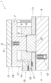
도 1 내지 4에 예시적으로 단순하게 작용하는 압축기로서 도시된 성형 툴(1)은 금속 시트, 금속 판(금속 블랭크), 및/또는 테일러드 블랭크(tailored blank)의 딥 드로우 작업을 수행한다. 도 1은 상기 성형 툴(1)의 개방 상태를 도시하는 것으로서, 성형 대상인 판(2)이 이미 삽입된 상태를 도시한다. 상기 성형 툴(1)의 이러한 개방 상태에서 상기 성형 툴(1)의 상기 제1, 2 수단(3), (4)을 볼 수 있다.The forming
상부의 상기 제1 툴 부재(3)는 하나의 툴 상부 부재(5), 다이(6), 및 블랭크 홀더(7)를 포함한다. 상기 블랭크 홀더(7)는 본 실시예에서 제1 가스 가압 스프링(108)으로 구현된 - 도 3 참조 - 제1 가압 수단(8)에 의해 상기 툴 상부 부재(5)에 지지된다. 상기 다이(6)는 상기 툴 상부 부재(5)에 단단히 결합된다.The
하부의 제2 툴 부재(4)는 툴 하부 부재(9), 펀치(10), 및 시트 홀더(11)를 포함한다. 상기 시트 홀더(11)는 제2 가스 가압 스프링(112)으로 구현된 - 도 3 참조 - 제2 가압 수단(12)에 의해 상기 툴 하부 부재(9)에 대하여 지지된다. 따라서 본 발명에 따른 성형 툴(1)은 하단 공기를 필요로 하지 않는다. 하단의 상기 하부 툴 부재(4)의 상기 펀치(10)는 상기 툴 하부 부재(9)에 고정되고 상기한 상단의 툴 부재(3)의 다이(6)와 함께 공동으로 상기 판(2)의 성형 작업을 수행한다.The lower
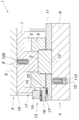
상기 성형 툴(1)은 또한 시트 홀더(11)와 블랭크 홀더(7) 사이에 구비되는 잠금 장치(13)를 포함한다. 상기 잠금 장치(13)는 스페이서(14)를 포함하며, 상기 스페이서(14)에 의해서 상기 시트 홀더(11)와 상기 블랭크 홀더(7)의 간격이 결정될 수 있다. 이러한 특징은 개방 상태의 상기 성형 툴(1)이 상기 제1, 2 가압 수단(8), (12)의 가압력이 잠재적으로 상이하더라도 상기 판(2) 등의 높은 성형 품질을 보장할 수 있게 하기 위해서 필수적이다. 이러한 잠금 장치(13)는 도 2에 도시된 바와 같이 상기 성형 툴(1)의 폐쇄 움직임을 통하여 작동된다. 도 1 내지 4를 함께 참조하면, 상기 스페이서(14)가 상기 성형 툴(1)의 폐쇄 시 발생하는 상대적 이동에 따라 이동 가능하게 장착되는 것을 알 수 있으며, 구체적으로, 상기 스페이서(14)가 상기 성형 툴(1)의 개방된 상태에서 자유로운, 도 1의 정지 위치(15)로부터 도 3의 작업 위치(16)로 이동 가능하게 장착됨을 알 수 있고, 이러한 이동에 따라 상기 성형 툴(1)의 개방 시 상기 시트 홀더(11)와 상기 블랭크 홀더(7) 사이의 간격이 결정된다.The forming
본 발명에 따르면, 상기 스페이서(14)의 이동은 상기 잠금 장치(13)에 포함되는 쐐기 드라이브(17)에 의해 제어된다. 또한, 상기 쐐기 드라이브(17)가 하나의 슬라이더(18) 및 하나의 드라이버(19)를 포함함으로써 이에 상응하는 가이드면(20)이 쐐기 드라이브(17)에 형성된다.According to the invention, the movement of the
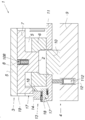
상기 슬라이더(18)는 상기 스페이서(14)를 포함하고 이동 가능하게 배치되며, 본 실시예의 경우 상기 시트 홀더(11)에 이동 가능하게 배치된다. 상기 슬라이더(18)는 상기 시트 홀더(11)와 상기 툴 상부 부재(5) 사이에 발생되는 상대적 이동에 따라 - 본 실시예에 따라 상기 툴 상부 부재(5)에 고정되는 상기 드라이버(19)와 접촉되어 - 이동되고, 이를 통하여 상기 스페이서(14)가 상기 블랭크 홀더(7) 아래로 이동됨으로써 상기 블랭크 홀더(7)가 상기 스페이서(14) 및 상기 시트 홀더(11)에 고정된다. 이로써 상기 스페이서(14)는 상기 블랭크 홀더(7)를 위한 방지 장치(24)를 형성한다. 이를 통하여 상기 시트 홀더(11)와 상기 블랭크 홀더(7) 사이의 간격이 결정되는데, 본 실시예의 경우 상기 스페이서(14)의 높이 및 상기 시트 홀더(11)에 대한 상기 스페이서(14)의 높이 차에 의해 결정되며, 상기 높이 차는 슬라이더(18)에서의 스페이서(14)의 위치에 의해 결정된다.The
이러한 방법을 통해, 높은 하중에도 상기 시트 홀더(11)와 상기 블랭크 홀더(7) 사이의 결정된 간격을 확실하게 조절할 수 있는 매우 견고한 잠금 장치(13)가 형성될 수 있다. 본 발명에 따른 상기 성형 툴(1)는 특히 높은 안정성을 제공한다.With this method, a very
도 1에서 알 수 있는 것과 같이, 상기 슬라이더(18)는 제3 가스 가압 스프링으로 구현되는 제1 스프링(21)의 작용에 대하여 이동 가능하게 장착된다. 상기 스프링(21)은 상기 슬라이더(18)와 상기 시트 홀더(11) 사이에서 작용하며, 상기 슬라이더(18)를 시트 홀더(11)상의 상기 스프링(21)의 제1 선형 가이드(22)를 따라서 가압하여 상기 다이(6)로부터 분리시킨다. 이를 통하여 상기 슬라이더(18)는 도 3의 상기 슬라이더(18)의 위치(23)에서 알 수 있는 바와 같이, 상기 스페이서(14)의 작업 위치(16)에서 상기 다이(6)에 대하여 가장 가까운 위치로 이동된다. 상기 스페이서(14)의 정지 위치(15)에서 상기 슬라이더(18)는 상기 다이(6)로부터 최대한 멀리 배치된다. 이를 통해 상기 성형 툴(1)의 재료 충전 시 발생하는 파열 윤곽이 방지된다.As can be seen in FIG. 1, the
또한, 도 1을 참조하면, 상기 블랭크 홀더(7)가 상기 다이(6)에서 방사상으로 돌출되고 상기 스페이서(14)의 방지 장치(24)에 대한 역 방지 장치(26)를 형성하는 숄더(25)를 형성함을 알 수 있다. 상기 역 방지 장치(26)는 상기 방사상으로 돌출되는 숄더(25)의 축 방향으로 돌출되는 부분(27) 상에 구비되고, 이를 통하여 상기 스페이서(14)가 그 높이에 비례하여 축소되어 구현될 수 있다.1, the
상기 스페이서(14)는 제2 스프링(28)의 작용에 대하여 상기 슬라이더(18)에 이동 가능하게 배치되는 것이 바람직하다. 제4 가스 가압 스프링으로 구현되는 상기 스프링(28)은 상기 스페이서(14)와 상기 슬라이더(18) 사이에 작용하며, 상기 스프링(28)의 제2 선형 가이드(31)를 따라서 상기 제1 스프링(21)의 작용 방향(30)과 반대되는 작용 방향(29)으로 상기 스페이서(14)에 하중을 가한다. 이를 통하여, 상기 스페이서(14)는 그 작업 위치(16)에서, 상기 제2 스프링(28)의 작업에 대응한 상기 스페이서(14)의 이동과 관련하여 도 2에 설명한 프리스트레싱 상태에 놓이게 된다.Preferably, the
또한, 도 1 내지 4를 통하여 상기 제1, 2 선형 가이드(22), (23)는 평행하게 연장됨을 알 수 있다.1 to 4, it can be seen that the first and second
도시되지는 않았지만, 일반적으로 상기 슬라이더(18)가 상기 툴 상부 부재(5)에 이동 가능하게 장착되고, 상기 드라이버는 상기 시트 홀더(11)에 고정될 수도 있다. 이 경우 역시 상기 스페이서(14)는 상기 시트 홀더(11)에 대한 방지 장치(24)를 형성하여 상기 시트 홀더(11)와 상기 블랭크 홀더(7) 사이의 간격을 결정한다. 또한, 마찬가지로 도시되지는 않았지만, 상기 스페이서(14)가 상기 시트 홀더(11)와 상기 블랭크 홀더(7)에 대한 방지 장치(24)를 각각 형성하는 것도 고려할 수 있다.Although not shown, generally, the
Claims (8)
툴 하부 부재(9), 상기 다이(6)와 공동 성형 작업하는 펀치(10), 및 이동 가능한 시트 홀더(11)를 포함하고, 상기 시트 홀더는 제2 가압 수단(12)에 의해 상기 툴 하부 부재(9)에 대하여 지지되는, 제2 툴 부재(4); 및
상기 시트 홀더(11)와 상기 블랭크 홀더(7) 사이에 구비되는 하나의 잠금 장치(13)를 포함하는 성형 툴로서, 상기 잠금 장치는 적어도 하나의 스페이서(14)를 포함하고, 이 때 상기 스페이서(14)는, 성형 툴(1)의 폐쇄시 발생하는 상대적 이동에 기반하여 정지 위치(15)로부터 작업 위치(16)로 이동 가능하게 장착되며, 상기 성형 툴(1)의 개방 시, 상기 시트 홀더(11)와 상기 블랭크 홀더(7) 사이의 간격을 결정하는, 성형 툴로서,
상기 잠금 장치(13)는 슬라이더(18) 및 드라이버(19)를 포함하는 적어도 하나의 쐐기 드라이브(17)를 구비하고,
상기 스페이서(14)를 포함하는 상기 슬라이더(18)는 상기 성형 툴(1)의 폐쇄 시 상기 시트 홀더(11)와 상기 툴 상부 부재(5) 사이에서 발생하는 상대적 이동에 기초하여 상기 드라이버(19)에 접촉한 상태로 이동 가능하게 장착됨으로써 상기 스페이서(14)를 스페이서의 작업 위치(16)로 이동시키는 것을 특징으로 하는 성형 툴.And a die 6 comprising a tool upper member 5 and a moveably inserted blank holder 7 which are held by the first pressing means 8 with the tool upper member 5 A first tool member (3) supported on the first tool member (3);
A punch (10) for co-molding with the die (6), and a movable sheet holder (11), the sheet holder being supported by a second pressing means (12) A second tool member (4) supported against the member (9); And
A molding tool comprising a locking device (13) provided between the seat holder (11) and the blank holder (7), the locking device comprising at least one spacer (14) (14) is movably mounted from a stop position (15) to a working position (16) based on the relative movement that occurs during closing of the forming tool (1) A molding tool for determining the distance between the holder (11) and the blank holder (7)
The locking device 13 comprises at least one wedge drive 17 comprising a slider 18 and a driver 19,
The slider 18 including the spacer 14 is configured to move relative to the driver 19 (19) on the basis of a relative movement occurring between the seat holder 11 and the tool upper member 5 when the forming tool 1 is closed. ) To move the spacer (14) to the working position (16) of the spacer.
Priority Applications (1)
| Application Number | Priority Date | Filing Date | Title |
|---|---|---|---|
| KR1020247000853A KR102775970B1 (en) | 2015-12-30 | 2016-12-23 | Locking device for a forming tool including a first tool member and a second tool member and Forming tool including the same |
Applications Claiming Priority (3)
| Application Number | Priority Date | Filing Date | Title |
|---|---|---|---|
| EP15203211.6 | 2015-12-30 | ||
| EP15203211.6A EP3187276A1 (en) | 2015-12-30 | 2015-12-30 | Forming tool |
| PCT/EP2016/082601 WO2017114790A1 (en) | 2015-12-30 | 2016-12-23 | Forming tool |
Related Child Applications (1)
| Application Number | Title | Priority Date | Filing Date |
|---|---|---|---|
| KR1020247000853A Division KR102775970B1 (en) | 2015-12-30 | 2016-12-23 | Locking device for a forming tool including a first tool member and a second tool member and Forming tool including the same |
Publications (2)
| Publication Number | Publication Date |
|---|---|
| KR20180098583A true KR20180098583A (en) | 2018-09-04 |
| KR102624949B1 KR102624949B1 (en) | 2024-01-15 |
Family
ID=55027613
Family Applications (2)
| Application Number | Title | Priority Date | Filing Date |
|---|---|---|---|
| KR1020247000853A Active KR102775970B1 (en) | 2015-12-30 | 2016-12-23 | Locking device for a forming tool including a first tool member and a second tool member and Forming tool including the same |
| KR1020187020354A Active KR102624949B1 (en) | 2015-12-30 | 2016-12-23 | forming tool |
Family Applications Before (1)
| Application Number | Title | Priority Date | Filing Date |
|---|---|---|---|
| KR1020247000853A Active KR102775970B1 (en) | 2015-12-30 | 2016-12-23 | Locking device for a forming tool including a first tool member and a second tool member and Forming tool including the same |
Country Status (11)
| Country | Link |
|---|---|
| US (1) | US11389852B2 (en) |
| EP (2) | EP3187276A1 (en) |
| JP (1) | JP6811780B2 (en) |
| KR (2) | KR102775970B1 (en) |
| CN (1) | CN108883454B (en) |
| BR (1) | BR112018013023B1 (en) |
| CA (1) | CA3010420C (en) |
| ES (1) | ES2789757T3 (en) |
| MX (1) | MX392908B (en) |
| SI (1) | SI3397408T1 (en) |
| WO (1) | WO2017114790A1 (en) |
Cited By (1)
| Publication number | Priority date | Publication date | Assignee | Title |
|---|---|---|---|---|
| KR102908393B1 (en) * | 2024-10-07 | 2026-01-12 | 주식회사 티앤지 | Method of manufacturing an enclosure for a columnar transformer in which bushing seat coupling holes are integrally formed |
Families Citing this family (5)
| Publication number | Priority date | Publication date | Assignee | Title |
|---|---|---|---|---|
| FR3074704B1 (en) * | 2017-12-07 | 2019-11-29 | Adm28 S.Ar.L | MAGNETO-FORMING INCREMENTAL PADDING DEVICE AND ASSOCIATED METHOD |
| US10786842B2 (en) * | 2018-09-12 | 2020-09-29 | Fca Us Llc | Draw-in control for sheet drawing |
| FR3095358B1 (en) * | 2019-04-24 | 2022-05-27 | Psa Automobiles Sa | STAMPING PRESS FOR METAL PLATES, WITH MECHANICAL LOCKING PIECE |
| US12138675B2 (en) * | 2020-01-09 | 2024-11-12 | Magna International Inc. | Adjustable balancing block for closed loop die control |
| WO2024259459A1 (en) * | 2023-06-21 | 2024-12-26 | Voestalpine Camtec Gmbh | Method for producing a shaped part, shaping tool and locking device |
Citations (6)
| Publication number | Priority date | Publication date | Assignee | Title |
|---|---|---|---|---|
| US20060101888A1 (en) * | 2004-11-16 | 2006-05-18 | Umix Co., Ltd. | Stabilizer of drawing die and stabilizer unit of the same |
| DE102011116714A1 (en) * | 2011-10-22 | 2013-04-25 | Volkswagen Aktiengesellschaft | Tool and method for thermoforming and cutting, in particular for press hardening and cutting, of a sheet metal material |
| US20140007640A1 (en) * | 2010-12-21 | 2014-01-09 | Showa Denko K.K. | Forging device |
| EP2754509A1 (en) * | 2011-09-09 | 2014-07-16 | M's Inc. | Press molding method and press molding device |
| US20150336619A1 (en) * | 2013-01-07 | 2015-11-26 | Nippon Steel & Sumitomo Metal Corporation | Press component and method and device for manufacturing same |
| US20160271682A1 (en) * | 2013-10-24 | 2016-09-22 | Nippon Steel & Sumitomo Metal Corporation | Hat-shaped cross-section component manufacturing apparatus and manufacturing method |
Family Cites Families (19)
| Publication number | Priority date | Publication date | Assignee | Title |
|---|---|---|---|---|
| SU1569055A1 (en) * | 1988-08-30 | 1990-06-07 | Институт сверхтвердых материалов АН УССР | Female die for drawing |
| FR2646623A1 (en) * | 1989-05-03 | 1990-11-09 | Peugeot | Press tool for deep-drawing slightly shaped workpieces |
| JPH07214185A (en) * | 1994-02-09 | 1995-08-15 | Kojima Press Co Ltd | Deep drawing die |
| JP3410613B2 (en) * | 1996-09-12 | 2003-05-26 | 本田技研工業株式会社 | Press forming method and apparatus for thin plate-like work |
| JP2005095909A (en) * | 2003-09-22 | 2005-04-14 | Jfe Steel Kk | Press forming method |
| DE102004059598B4 (en) * | 2004-12-09 | 2014-02-27 | Volkswagen Ag | Device for forming and hardening a sheet |
| DE102009028769A1 (en) * | 2009-08-21 | 2011-02-24 | Ford Global Technologies, LLC, Dearborn | Double-acting thermoforming device for shaping metal sheets, has drive device comprising deflection device interconnected between drawing punch and draw bead so that movement step of fitting of bead and drawing groove is drivable by punch |
| DE102011120789B4 (en) * | 2011-12-10 | 2018-07-19 | Audi Ag | Process for finishing a blank forming tool |
| CN102717028B (en) * | 2012-07-05 | 2014-06-18 | 无锡鹰普精密铸造有限公司 | Wax injector die |
| CN202985956U (en) * | 2012-12-21 | 2013-06-12 | 安徽中铁施封锁有限公司 | Plastic-coating mould for fastening type sealed lock body |
| JP2014217870A (en) * | 2013-05-10 | 2014-11-20 | トヨタ自動車東日本株式会社 | Press molding machine |
| CN105682819B (en) * | 2013-09-24 | 2017-10-13 | 新日铁住金株式会社 | Manufacturing equipment for hat-shaped cross-section parts |
| CN203649140U (en) * | 2013-10-11 | 2014-06-18 | 广东骏汇汽车科技股份有限公司 | Fine-blanking progressive mold for pressing bevel edge on steel back |
| FR3021239B1 (en) * | 2014-05-20 | 2016-12-23 | Peugeot Citroen Automobiles Sa | CONTROL DEVICE SUITABLE FOR USE IN A MAIN BINDING TOOL AND PROVIDED WITH AN AUXILIARY BINDING SLIDER |
| CN203917636U (en) * | 2014-06-24 | 2014-11-05 | 蚌埠国威滤清器有限公司 | A kind of beading and flange compound die |
| KR101611735B1 (en) | 2014-10-13 | 2016-04-14 | 주식회사 포스코 | Apparatus and method for press forming |
| HUE044534T2 (en) * | 2015-03-09 | 2019-10-28 | Autotech Eng Sl | Press systems and methods |
| FR3047680B1 (en) * | 2016-02-12 | 2018-07-13 | Peugeot Citroen Automobiles Sa | PRESS FOR FORMING A FLAN OF A SHEET AND A METHOD OF BINDING THE SAME |
| KR20170133955A (en) * | 2016-05-27 | 2017-12-06 | 주식회사 성우하이텍 | Draw press system |
-
2015
- 2015-12-30 EP EP15203211.6A patent/EP3187276A1/en not_active Withdrawn
-
2016
- 2016-12-23 SI SI201630719T patent/SI3397408T1/en unknown
- 2016-12-23 JP JP2018533787A patent/JP6811780B2/en active Active
- 2016-12-23 EP EP16828948.6A patent/EP3397408B1/en active Active
- 2016-12-23 WO PCT/EP2016/082601 patent/WO2017114790A1/en not_active Ceased
- 2016-12-23 MX MX2018008188A patent/MX392908B/en unknown
- 2016-12-23 KR KR1020247000853A patent/KR102775970B1/en active Active
- 2016-12-23 CN CN201680077374.0A patent/CN108883454B/en active Active
- 2016-12-23 BR BR112018013023-0A patent/BR112018013023B1/en active IP Right Grant
- 2016-12-23 US US16/067,607 patent/US11389852B2/en active Active
- 2016-12-23 KR KR1020187020354A patent/KR102624949B1/en active Active
- 2016-12-23 CA CA3010420A patent/CA3010420C/en active Active
- 2016-12-23 ES ES16828948T patent/ES2789757T3/en active Active
Patent Citations (6)
| Publication number | Priority date | Publication date | Assignee | Title |
|---|---|---|---|---|
| US20060101888A1 (en) * | 2004-11-16 | 2006-05-18 | Umix Co., Ltd. | Stabilizer of drawing die and stabilizer unit of the same |
| US20140007640A1 (en) * | 2010-12-21 | 2014-01-09 | Showa Denko K.K. | Forging device |
| EP2754509A1 (en) * | 2011-09-09 | 2014-07-16 | M's Inc. | Press molding method and press molding device |
| DE102011116714A1 (en) * | 2011-10-22 | 2013-04-25 | Volkswagen Aktiengesellschaft | Tool and method for thermoforming and cutting, in particular for press hardening and cutting, of a sheet metal material |
| US20150336619A1 (en) * | 2013-01-07 | 2015-11-26 | Nippon Steel & Sumitomo Metal Corporation | Press component and method and device for manufacturing same |
| US20160271682A1 (en) * | 2013-10-24 | 2016-09-22 | Nippon Steel & Sumitomo Metal Corporation | Hat-shaped cross-section component manufacturing apparatus and manufacturing method |
Cited By (1)
| Publication number | Priority date | Publication date | Assignee | Title |
|---|---|---|---|---|
| KR102908393B1 (en) * | 2024-10-07 | 2026-01-12 | 주식회사 티앤지 | Method of manufacturing an enclosure for a columnar transformer in which bushing seat coupling holes are integrally formed |
Also Published As
| Publication number | Publication date |
|---|---|
| US20190009322A1 (en) | 2019-01-10 |
| US11389852B2 (en) | 2022-07-19 |
| BR112018013023B1 (en) | 2021-11-03 |
| CA3010420A1 (en) | 2017-07-06 |
| KR20240014576A (en) | 2024-02-01 |
| CN108883454B (en) | 2020-09-11 |
| EP3187276A1 (en) | 2017-07-05 |
| JP2019500219A (en) | 2019-01-10 |
| EP3397408B1 (en) | 2020-02-05 |
| CN108883454A (en) | 2018-11-23 |
| BR112018013023A2 (en) | 2018-12-04 |
| WO2017114790A1 (en) | 2017-07-06 |
| MX392908B (en) | 2025-03-21 |
| SI3397408T1 (en) | 2020-07-31 |
| JP6811780B2 (en) | 2021-01-13 |
| KR102624949B1 (en) | 2024-01-15 |
| ES2789757T8 (en) | 2022-02-28 |
| KR102775970B1 (en) | 2025-03-04 |
| EP3397408A1 (en) | 2018-11-07 |
| CA3010420C (en) | 2024-01-09 |
| MX2018008188A (en) | 2018-11-09 |
| ES2789757T3 (en) | 2020-10-26 |
Similar Documents
| Publication | Publication Date | Title |
|---|---|---|
| KR20180098583A (en) | Molding tool | |
| KR101779688B1 (en) | Press forming method and press forming device | |
| JP4994985B2 (en) | Secondary press mold for manufacturing wing protection members | |
| KR101846760B1 (en) | Press molding device, production method for press molded article using said molding device, and press molded article | |
| JP5423302B2 (en) | Workpiece manufacturing apparatus and method | |
| CN104368681B (en) | Wedge mechanism | |
| CN112496137B (en) | Apparatus and method for manufacturing hat-shaped cross-section member having curved convex portion | |
| KR102003631B1 (en) | Press forming method and tool of press forming | |
| CN107150093A (en) | Process the device of board and adjustable spacing devices available for the device | |
| JP5938074B2 (en) | Drawing method and apparatus | |
| CN104275381A (en) | Die cutting molding apparatus for preventing a product from getting imprinted | |
| US11498108B2 (en) | Manufacturing apparatus and manufacturing method for hat-shaped cross-section component | |
| KR101963065B1 (en) | Cutting device and cutting method | |
| CN106334758B (en) | Rise and fall violent stamping parts shaping mould | |
| KR101647211B1 (en) | Flexible die apparatus and pressing method using thereof | |
| KR101432776B1 (en) | Knock-out device for impact press forming machine | |
| KR101748964B1 (en) | Material bending machine | |
| JP2016034647A (en) | Press molding method and press molding apparatus | |
| KR101461793B1 (en) | apparatus for press-forming | |
| JP2010000541A6 (en) | Press device for molding safety device parts | |
| JP2010000541A (en) | Press apparatus for forming safety device parts | |
| JP2007118017A (en) | Double-action press device and press method | |
| JP5933299B2 (en) | Press forming equipment | |
| KR101401761B1 (en) | Forming method for bending a flange hub and forming apparatus for bending a flange hub | |
| JP2014184464A (en) | Multistage press apparatus |
Legal Events
| Date | Code | Title | Description |
|---|---|---|---|
| PA0105 | International application |
Patent event date: 20180716 Patent event code: PA01051R01D Comment text: International Patent Application |
|
| PG1501 | Laying open of application | ||
| N231 | Notification of change of applicant | ||
| PN2301 | Change of applicant |
Patent event date: 20190426 Comment text: Notification of Change of Applicant Patent event code: PN23011R01D |
|
| A201 | Request for examination | ||
| PA0201 | Request for examination |
Patent event code: PA02012R01D Patent event date: 20211123 Comment text: Request for Examination of Application |
|
| E902 | Notification of reason for refusal | ||
| PE0902 | Notice of grounds for rejection |
Comment text: Notification of reason for refusal Patent event date: 20230515 Patent event code: PE09021S01D |
|
| E701 | Decision to grant or registration of patent right | ||
| PE0701 | Decision of registration |
Patent event code: PE07011S01D Comment text: Decision to Grant Registration Patent event date: 20231010 |
|
| GRNT | Written decision to grant | ||
| PR0701 | Registration of establishment |
Comment text: Registration of Establishment Patent event date: 20240110 Patent event code: PR07011E01D |
|
| PR1002 | Payment of registration fee |
Payment date: 20240110 End annual number: 3 Start annual number: 1 |
|
| PG1601 | Publication of registration |