KR20180098578A - Cobalt-containing film-forming composition, its synthesis, and its use in film deposition - Google Patents
Cobalt-containing film-forming composition, its synthesis, and its use in film deposition Download PDFInfo
- Publication number
- KR20180098578A KR20180098578A KR1020187020024A KR20187020024A KR20180098578A KR 20180098578 A KR20180098578 A KR 20180098578A KR 1020187020024 A KR1020187020024 A KR 1020187020024A KR 20187020024 A KR20187020024 A KR 20187020024A KR 20180098578 A KR20180098578 A KR 20180098578A
- Authority
- KR
- South Korea
- Prior art keywords
- forming composition
- sime
- film forming
- containing film
- precursor
- Prior art date
- Legal status (The legal status is an assumption and is not a legal conclusion. Google has not performed a legal analysis and makes no representation as to the accuracy of the status listed.)
- Granted
Links
Images


Classifications
-
- C—CHEMISTRY; METALLURGY
- C23—COATING METALLIC MATERIAL; COATING MATERIAL WITH METALLIC MATERIAL; CHEMICAL SURFACE TREATMENT; DIFFUSION TREATMENT OF METALLIC MATERIAL; COATING BY VACUUM EVAPORATION, BY SPUTTERING, BY ION IMPLANTATION OR BY CHEMICAL VAPOUR DEPOSITION, IN GENERAL; INHIBITING CORROSION OF METALLIC MATERIAL OR INCRUSTATION IN GENERAL
- C23C—COATING METALLIC MATERIAL; COATING MATERIAL WITH METALLIC MATERIAL; SURFACE TREATMENT OF METALLIC MATERIAL BY DIFFUSION INTO THE SURFACE, BY CHEMICAL CONVERSION OR SUBSTITUTION; COATING BY VACUUM EVAPORATION, BY SPUTTERING, BY ION IMPLANTATION OR BY CHEMICAL VAPOUR DEPOSITION, IN GENERAL
- C23C16/00—Chemical coating by decomposition of gaseous compounds, without leaving reaction products of surface material in the coating, i.e. chemical vapour deposition [CVD] processes
- C23C16/06—Chemical coating by decomposition of gaseous compounds, without leaving reaction products of surface material in the coating, i.e. chemical vapour deposition [CVD] processes characterised by the deposition of metallic material
- C23C16/18—Chemical coating by decomposition of gaseous compounds, without leaving reaction products of surface material in the coating, i.e. chemical vapour deposition [CVD] processes characterised by the deposition of metallic material from metallo-organic compounds
-
- C—CHEMISTRY; METALLURGY
- C23—COATING METALLIC MATERIAL; COATING MATERIAL WITH METALLIC MATERIAL; CHEMICAL SURFACE TREATMENT; DIFFUSION TREATMENT OF METALLIC MATERIAL; COATING BY VACUUM EVAPORATION, BY SPUTTERING, BY ION IMPLANTATION OR BY CHEMICAL VAPOUR DEPOSITION, IN GENERAL; INHIBITING CORROSION OF METALLIC MATERIAL OR INCRUSTATION IN GENERAL
- C23C—COATING METALLIC MATERIAL; COATING MATERIAL WITH METALLIC MATERIAL; SURFACE TREATMENT OF METALLIC MATERIAL BY DIFFUSION INTO THE SURFACE, BY CHEMICAL CONVERSION OR SUBSTITUTION; COATING BY VACUUM EVAPORATION, BY SPUTTERING, BY ION IMPLANTATION OR BY CHEMICAL VAPOUR DEPOSITION, IN GENERAL
- C23C16/00—Chemical coating by decomposition of gaseous compounds, without leaving reaction products of surface material in the coating, i.e. chemical vapour deposition [CVD] processes
- C23C16/22—Chemical coating by decomposition of gaseous compounds, without leaving reaction products of surface material in the coating, i.e. chemical vapour deposition [CVD] processes characterised by the deposition of inorganic material, other than metallic material
- C23C16/30—Deposition of compounds, mixtures or solid solutions, e.g. borides, carbides, nitrides
- C23C16/34—Nitrides
-
- C—CHEMISTRY; METALLURGY
- C23—COATING METALLIC MATERIAL; COATING MATERIAL WITH METALLIC MATERIAL; CHEMICAL SURFACE TREATMENT; DIFFUSION TREATMENT OF METALLIC MATERIAL; COATING BY VACUUM EVAPORATION, BY SPUTTERING, BY ION IMPLANTATION OR BY CHEMICAL VAPOUR DEPOSITION, IN GENERAL; INHIBITING CORROSION OF METALLIC MATERIAL OR INCRUSTATION IN GENERAL
- C23C—COATING METALLIC MATERIAL; COATING MATERIAL WITH METALLIC MATERIAL; SURFACE TREATMENT OF METALLIC MATERIAL BY DIFFUSION INTO THE SURFACE, BY CHEMICAL CONVERSION OR SUBSTITUTION; COATING BY VACUUM EVAPORATION, BY SPUTTERING, BY ION IMPLANTATION OR BY CHEMICAL VAPOUR DEPOSITION, IN GENERAL
- C23C16/00—Chemical coating by decomposition of gaseous compounds, without leaving reaction products of surface material in the coating, i.e. chemical vapour deposition [CVD] processes
- C23C16/22—Chemical coating by decomposition of gaseous compounds, without leaving reaction products of surface material in the coating, i.e. chemical vapour deposition [CVD] processes characterised by the deposition of inorganic material, other than metallic material
- C23C16/30—Deposition of compounds, mixtures or solid solutions, e.g. borides, carbides, nitrides
- C23C16/42—Silicides
-
- C—CHEMISTRY; METALLURGY
- C23—COATING METALLIC MATERIAL; COATING MATERIAL WITH METALLIC MATERIAL; CHEMICAL SURFACE TREATMENT; DIFFUSION TREATMENT OF METALLIC MATERIAL; COATING BY VACUUM EVAPORATION, BY SPUTTERING, BY ION IMPLANTATION OR BY CHEMICAL VAPOUR DEPOSITION, IN GENERAL; INHIBITING CORROSION OF METALLIC MATERIAL OR INCRUSTATION IN GENERAL
- C23C—COATING METALLIC MATERIAL; COATING MATERIAL WITH METALLIC MATERIAL; SURFACE TREATMENT OF METALLIC MATERIAL BY DIFFUSION INTO THE SURFACE, BY CHEMICAL CONVERSION OR SUBSTITUTION; COATING BY VACUUM EVAPORATION, BY SPUTTERING, BY ION IMPLANTATION OR BY CHEMICAL VAPOUR DEPOSITION, IN GENERAL
- C23C16/00—Chemical coating by decomposition of gaseous compounds, without leaving reaction products of surface material in the coating, i.e. chemical vapour deposition [CVD] processes
- C23C16/44—Chemical coating by decomposition of gaseous compounds, without leaving reaction products of surface material in the coating, i.e. chemical vapour deposition [CVD] processes characterised by the method of coating
- C23C16/448—Chemical coating by decomposition of gaseous compounds, without leaving reaction products of surface material in the coating, i.e. chemical vapour deposition [CVD] processes characterised by the method of coating characterised by the method used for generating reactive gas streams, e.g. by evaporation or sublimation of precursor materials
- C23C16/4481—Chemical coating by decomposition of gaseous compounds, without leaving reaction products of surface material in the coating, i.e. chemical vapour deposition [CVD] processes characterised by the method of coating characterised by the method used for generating reactive gas streams, e.g. by evaporation or sublimation of precursor materials by evaporation using carrier gas in contact with the source material
-
- C—CHEMISTRY; METALLURGY
- C23—COATING METALLIC MATERIAL; COATING MATERIAL WITH METALLIC MATERIAL; CHEMICAL SURFACE TREATMENT; DIFFUSION TREATMENT OF METALLIC MATERIAL; COATING BY VACUUM EVAPORATION, BY SPUTTERING, BY ION IMPLANTATION OR BY CHEMICAL VAPOUR DEPOSITION, IN GENERAL; INHIBITING CORROSION OF METALLIC MATERIAL OR INCRUSTATION IN GENERAL
- C23C—COATING METALLIC MATERIAL; COATING MATERIAL WITH METALLIC MATERIAL; SURFACE TREATMENT OF METALLIC MATERIAL BY DIFFUSION INTO THE SURFACE, BY CHEMICAL CONVERSION OR SUBSTITUTION; COATING BY VACUUM EVAPORATION, BY SPUTTERING, BY ION IMPLANTATION OR BY CHEMICAL VAPOUR DEPOSITION, IN GENERAL
- C23C16/00—Chemical coating by decomposition of gaseous compounds, without leaving reaction products of surface material in the coating, i.e. chemical vapour deposition [CVD] processes
- C23C16/44—Chemical coating by decomposition of gaseous compounds, without leaving reaction products of surface material in the coating, i.e. chemical vapour deposition [CVD] processes characterised by the method of coating
- C23C16/455—Chemical coating by decomposition of gaseous compounds, without leaving reaction products of surface material in the coating, i.e. chemical vapour deposition [CVD] processes characterised by the method of coating characterised by the method used for introducing gases into reaction chamber or for modifying gas flows in reaction chamber
- C23C16/45523—Pulsed gas flow or change of composition over time
- C23C16/45525—Atomic layer deposition [ALD]
- C23C16/45527—Atomic layer deposition [ALD] characterized by the ALD cycle, e.g. different flows or temperatures during half-reactions, unusual pulsing sequence, use of precursor mixtures or auxiliary reactants or activations
- C23C16/45536—Use of plasma, radiation or electromagnetic fields
-
- C—CHEMISTRY; METALLURGY
- C23—COATING METALLIC MATERIAL; COATING MATERIAL WITH METALLIC MATERIAL; CHEMICAL SURFACE TREATMENT; DIFFUSION TREATMENT OF METALLIC MATERIAL; COATING BY VACUUM EVAPORATION, BY SPUTTERING, BY ION IMPLANTATION OR BY CHEMICAL VAPOUR DEPOSITION, IN GENERAL; INHIBITING CORROSION OF METALLIC MATERIAL OR INCRUSTATION IN GENERAL
- C23C—COATING METALLIC MATERIAL; COATING MATERIAL WITH METALLIC MATERIAL; SURFACE TREATMENT OF METALLIC MATERIAL BY DIFFUSION INTO THE SURFACE, BY CHEMICAL CONVERSION OR SUBSTITUTION; COATING BY VACUUM EVAPORATION, BY SPUTTERING, BY ION IMPLANTATION OR BY CHEMICAL VAPOUR DEPOSITION, IN GENERAL
- C23C16/00—Chemical coating by decomposition of gaseous compounds, without leaving reaction products of surface material in the coating, i.e. chemical vapour deposition [CVD] processes
- C23C16/44—Chemical coating by decomposition of gaseous compounds, without leaving reaction products of surface material in the coating, i.e. chemical vapour deposition [CVD] processes characterised by the method of coating
- C23C16/455—Chemical coating by decomposition of gaseous compounds, without leaving reaction products of surface material in the coating, i.e. chemical vapour deposition [CVD] processes characterised by the method of coating characterised by the method used for introducing gases into reaction chamber or for modifying gas flows in reaction chamber
- C23C16/45523—Pulsed gas flow or change of composition over time
- C23C16/45525—Atomic layer deposition [ALD]
- C23C16/45553—Atomic layer deposition [ALD] characterized by the use of precursors specially adapted for ALD
-
- H01L21/02697—
-
- H01L21/28556—
-
- H01L21/28568—
-
- H01L21/76841—
-
- H—ELECTRICITY
- H10—SEMICONDUCTOR DEVICES; ELECTRIC SOLID-STATE DEVICES NOT OTHERWISE PROVIDED FOR
- H10P—GENERIC PROCESSES OR APPARATUS FOR THE MANUFACTURE OR TREATMENT OF DEVICES COVERED BY CLASS H10
- H10P14/00—Formation of materials, e.g. in the shape of layers or pillars
- H10P14/40—Formation of materials, e.g. in the shape of layers or pillars of conductive or resistive materials
- H10P14/418—Formation of materials, e.g. in the shape of layers or pillars of conductive or resistive materials the conductive layers comprising transition metals
-
- H—ELECTRICITY
- H10—SEMICONDUCTOR DEVICES; ELECTRIC SOLID-STATE DEVICES NOT OTHERWISE PROVIDED FOR
- H10P—GENERIC PROCESSES OR APPARATUS FOR THE MANUFACTURE OR TREATMENT OF DEVICES COVERED BY CLASS H10
- H10P14/00—Formation of materials, e.g. in the shape of layers or pillars
- H10P14/40—Formation of materials, e.g. in the shape of layers or pillars of conductive or resistive materials
- H10P14/42—Formation of materials, e.g. in the shape of layers or pillars of conductive or resistive materials using a gas or vapour
- H10P14/43—Chemical deposition, e.g. chemical vapour deposition [CVD]
-
- H—ELECTRICITY
- H10—SEMICONDUCTOR DEVICES; ELECTRIC SOLID-STATE DEVICES NOT OTHERWISE PROVIDED FOR
- H10W—GENERIC PACKAGES, INTERCONNECTIONS, CONNECTORS OR OTHER CONSTRUCTIONAL DETAILS OF DEVICES COVERED BY CLASS H10
- H10W20/00—Interconnections in chips, wafers or substrates
- H10W20/01—Manufacture or treatment
- H10W20/031—Manufacture or treatment of conductive parts of the interconnections
- H10W20/032—Manufacture or treatment of conductive parts of the interconnections of conductive barrier, adhesion or liner layers
-
- H—ELECTRICITY
- H10—SEMICONDUCTOR DEVICES; ELECTRIC SOLID-STATE DEVICES NOT OTHERWISE PROVIDED FOR
- H10D—INORGANIC ELECTRIC SEMICONDUCTOR DEVICES
- H10D64/00—Electrodes of devices having potential barriers
- H10D64/01—Manufacture or treatment
- H10D64/011—Manufacture or treatment of electrodes ohmically coupled to a semiconductor
- H10D64/0111—Manufacture or treatment of electrodes ohmically coupled to a semiconductor to Group IV semiconductors
- H10D64/0112—Manufacture or treatment of electrodes ohmically coupled to a semiconductor to Group IV semiconductors using conductive layers comprising silicides
-
- H—ELECTRICITY
- H10—SEMICONDUCTOR DEVICES; ELECTRIC SOLID-STATE DEVICES NOT OTHERWISE PROVIDED FOR
- H10W—GENERIC PACKAGES, INTERCONNECTIONS, CONNECTORS OR OTHER CONSTRUCTIONAL DETAILS OF DEVICES COVERED BY CLASS H10
- H10W20/00—Interconnections in chips, wafers or substrates
- H10W20/01—Manufacture or treatment
- H10W20/021—Manufacture or treatment of interconnections within wafers or substrates
- H10W20/023—Manufacture or treatment of interconnections within wafers or substrates the interconnections being through-semiconductor vias
-
- H—ELECTRICITY
- H10—SEMICONDUCTOR DEVICES; ELECTRIC SOLID-STATE DEVICES NOT OTHERWISE PROVIDED FOR
- H10W—GENERIC PACKAGES, INTERCONNECTIONS, CONNECTORS OR OTHER CONSTRUCTIONAL DETAILS OF DEVICES COVERED BY CLASS H10
- H10W20/00—Interconnections in chips, wafers or substrates
- H10W20/01—Manufacture or treatment
- H10W20/031—Manufacture or treatment of conductive parts of the interconnections
- H10W20/032—Manufacture or treatment of conductive parts of the interconnections of conductive barrier, adhesion or liner layers
- H10W20/033—Manufacture or treatment of conductive parts of the interconnections of conductive barrier, adhesion or liner layers in openings in dielectrics
Landscapes
- Chemical & Material Sciences (AREA)
- Engineering & Computer Science (AREA)
- General Chemical & Material Sciences (AREA)
- Chemical Kinetics & Catalysis (AREA)
- Metallurgy (AREA)
- Mechanical Engineering (AREA)
- Materials Engineering (AREA)
- Organic Chemistry (AREA)
- Inorganic Chemistry (AREA)
- Physics & Mathematics (AREA)
- Electromagnetism (AREA)
- Plasma & Fusion (AREA)
- Chemical Vapour Deposition (AREA)
- Crystallography & Structural Chemistry (AREA)
- Electrodes Of Semiconductors (AREA)
Abstract
코발트-함유 막 형성 조성물, 이의 제조, 및 막의 증기 증착을 위한 이의 용도가 개시된다. 코발트-함유 막 형성 조성물은 실릴아미드-함유 전구체, 특히, Co[N(SiMe3)2]2(NMe2Et) 및/또는 Co[N(SiMe3)2]2(NMeEt2)를 포함한다.Cobalt-containing film forming compositions, their preparation, and their use for vapor deposition of films are disclosed. The cobalt-containing film-forming composition comprises a silylamide-containing precursor, particularly Co [N (SiMe 3 ) 2 ] 2 (NMe 2 Et) and / or Co [N (SiMe 3 ) 2 ] 2 (NMeEt 2 ) .
Description
관련 출원에 대한 상호 참조문헌Cross-references to Related Applications
본 출원은 2015년 12월 31일에 출원된 미국특허출원번호 제14/986,286호의 이익을 주장하며, 이러한 문헌은 전문이 모든 목적을 위하여 본원에 참고로 포함된다.This application claims the benefit of U.S. Patent Application Serial No. 14 / 986,286, filed December 31, 2015, which is incorporated herein by reference in its entirety for all purposes.
기술 분야Technical field
코발트-함유 막 형성 조성물, 이의 제조, 및 막의 증기 증착을 위한 이의 용도가 개시된다. 코발트-함유 막 형성 조성물은 실릴아미드-함유 전구체, 특히, Co[N(SiMe3)2]2(NMe2Et) 및/또는 Co[N(SiMe3)2]2(NMeEt2)를 포함한다.Cobalt-containing film forming compositions, their preparation, and their use for vapor deposition of films are disclosed. The cobalt-containing film-forming composition comprises a silylamide-containing precursor, particularly Co [N (SiMe 3 ) 2 ] 2 (NMe 2 Et) and / or Co [N (SiMe 3 ) 2 ] 2 (NMeEt 2 ) .
화학적 증기 증착(CVD) 및 원자층 증착(ALD)은 반도체 소자를 위한 박막을 생성하기 위한 주요 증착 기술로서 적용되고 있다. 이러한 방법은 증착 공정 동안 파라미터의 미세조정을 통해 컨포멀 막(conformal film)(금속, 옥사이드, 니트라이드, 실리사이드, 등)의 달성을 가능하게 한다. 주로 막 성장은 금속-함유 화합물(전구체)의 화학적 반응에 의해 제어되며, 최적의 전구체의 개발은 이의 성질 및 반응 공정의 예측 시에 필수적이다.Chemical vapor deposition (CVD) and atomic layer deposition (ALD) have been applied as key deposition techniques to create thin films for semiconductor devices. This method enables the achievement of conformal films (metals, oxides, nitrides, silicides, etc.) through fine tuning of parameters during the deposition process. Mainly the film growth is controlled by the chemical reaction of the metal-containing compound (precursor), and the development of the optimal precursor is essential in its properties and in predicting the reaction process.
전이 금속 및 전이 금속 실리사이드, 특히, 망간, 철, 코발트, 및 루테늄의 막은 다양한 전자기기 및 전기화학적 적용에서 중요해지고 있다. 예를 들어, 코발트 박막은 이의 높은 자기 유전율(magnetic permittivity)로 인하여 고려되고 있다. 반도체 소자의 프론트-엔드-오브-더-라인(front-end-of-the-line) 가공에서 이의 낮은 저항률로 인해 옴 접촉(Ohmic Contact)을 위한 코발트 디실리사이드(CoSi2)를 형성하기 위해 코발트 박막을 사용하는 다수의 보고서가 존재한다. 코발트 함유 박막은 최근에, 초대형 집적 소자를 위한 Cu/저-k 배리어, 패시베이션 층, 및 캡핑 층으로서 연구되었다.Transition metals and transition metal silicides, especially films of manganese, iron, cobalt, and ruthenium, have become important in a variety of electronic and electrochemical applications. For example, cobalt films are being considered due to their high magnetic permittivity. Due to its low resistivity in the front-end-of-the-line processing of semiconductor devices, cobalt (CoSi 2 ) There are a number of reports using thin films. Cobalt-containing thin films have recently been studied as Cu / low-k barriers, passivation layers, and capping layers for very large integrated devices.
실릴아미드 화합물의 합성이 보고되었다(Monatsh. Chem. (1963), 94(6), pp.1007-1012; Polyhedron 22 (2003) pp.67-73, J.C.S.Chem.Comm. (1972) pp.872-873; Inorg. Chem. (1984) 23, 4584-4588; US 6969539B2). 실릴아미드 화합물을 사용한 증기 증착 막 형성이 또한 보고되었다(Chem.Vap.Deposition 1995, 1, No. 2, 49-51; R.G.Gordon 등; US 2009/0053426A1 Applied Materials; US 2014/0255606 Applied Materials).(1963), 94 (6), pp. 1007-1012; Polyhedron 22 (2003) pp.67-73, JCS Chem. Comm. (1972) pp.872 -873; Inorg. Chem. (1984) 23, 4584-4588; US 6969539B2). Vapor deposition film formation using silylamide compounds has also been reported (Chem.Vap.
US 6969539호(Gordon 등)에는 하기가 개시되어 있다:US 6969539 (Gordon et al) discloses:
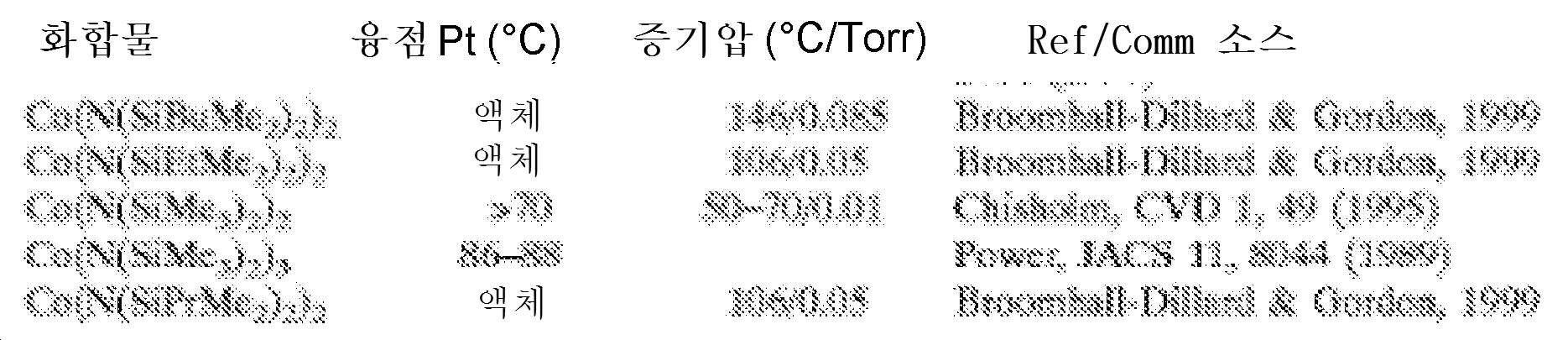
당업자는, 액체 형태의 Co-함유 전구체가 증기 증착 방법을 위해 바람직하지만, 박막 증착을 위한 산업적 사용에는 개시된 증기압이 너무 낮다는 것을 인식할 것이다.Those skilled in the art will appreciate that although the Co-containing precursor in liquid form is preferred for vapor deposition processes, the disclosed vapor pressures are too low for industrial use for thin film deposition.
증기상 막 증착에서 사용하기에 충분히 안정하면서 적합하게 휘발성인 Co-함유 전구체를 선택하는 것은 상업적 실행에서 중요하고, 항상 용이하게 결정되는 것은 아니다.Choosing a suitably volatile Co-containing precursor that is stable enough for use in vapor phase film deposition is important in commercial practice and is not always readily determinable.
하기 화학식을 갖는 실릴아미드-함유 전구체를 포함하는 코발트-함유 막 형성 조성물이 개시된다:Disclosed is a cobalt-containing film forming composition comprising a silylamide-containing precursor having the formula:
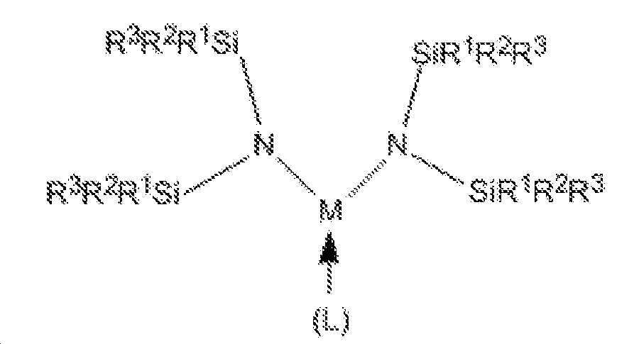
[화학식 I](I)

[화학식 II]≪ RTI ID = 0.0 &
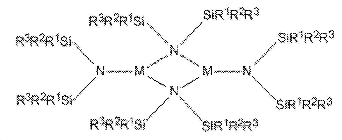
(상기 식에서, M은 Co이며; 각 R1, R2 및 R3은 독립적으로 수소(H) 또는 C1-C4 탄화수소로부터 선택되며; L은 피리딘, NMe3, NEt3, NMe2Et, NMeEt2, 1-Me-피롤리딘, 또는 PMe3으로부터 선택된 하나 또는 두 개의 중성 부가물이며; R1 및 R2, 또는 R2 및 R3은 결합되어 환형 규소-함유 헤테로사이클을 형성할 수 있음). 개시된 실릴아미드-함유 막 형성 조성물은 하기 양태들 중 하나 이상을 가질 수 있다:NMe 3 , NEt 3 , NMe 2 Et, NMeEt 2 (wherein, M is Co and each R 1 , R 2 and R 3 are independently selected from hydrogen (H) or C 1 -
● 각 R1, R2 및 R3은 독립적으로 H, 메틸, 에틸, 이소프로필, n-프로필, n-부틸, 또는 t-부틸로부터 선택됨;Each R 1 , R 2 and R 3 is independently selected from H, methyl, ethyl, isopropyl, n-propyl, n-butyl or t-butyl;
● 실릴아미드-함유 전구체는 {Co[N(SiMe3)2]2}2임; The silylamide-containing precursor is {Co [N (SiMe 3 ) 2 ] 2 } 2 ;
● 실릴아미드-함유 전구체는 Co[N(SiMe3)2]2(py)임; The silylamide-containing precursor is Co [N (SiMe 3 ) 2 ] 2 (py);
● 실릴아미드-함유 전구체는 Co[N(SiMe3)2]2(Me3N)임; The silylamide-containing precursor is Co [N (SiMe 3 ) 2 ] 2 (Me 3 N);
● 실릴아미드-함유 전구체는 Co[N(SiMe3)2]2(Et3N)임; ● silyl amide-containing precursor Co [N (SiMe 3) 2 ] 2 (Et 3 N) Im;
● 실릴아미드-함유 전구체는 Co[N(SiMe3)2]2(Me2EtN)임; The silylamide-containing precursor is Co [N (SiMe 3 ) 2 ] 2 (Me 2 EtN);
● 실릴아미드-함유 전구체는 Co[N(SiMe3)2]2(MeEt2N)임; The silylamide-containing precursor is Co [N (SiMe 3 ) 2 ] 2 (MeEt 2 N);
● 실릴아미드-함유 전구체는 Co[N(SiMe3)2]2(1-Me-피롤리딘)임; The silylamide-containing precursor is Co [N (SiMe 3 ) 2 ] 2 (1-Me-pyrrolidine);
● 실릴아미드-함유 전구체는 Co[N(SiMe3)2]2(PMe3)임; ● silyl amide-containing precursor Co [N (SiMe 3) 2 ] 2 (PMe 3) Im;
● 실릴아미드-함유 전구체는 {Co[N(SiMe2Et)2]2}2임;The silylamide-containing precursor is {Co [N (SiMe 2 Et) 2 ] 2 } 2 ;
● 실릴아미드-함유 전구체는 Co[N(SiMe2Et)2]2(py)임;The silylamide-containing precursor is Co [N (SiMe 2 Et) 2 ] 2 (py);
● 실릴아미드-함유 전구체는 Co[N(SiMe2Et)2]2(Me3N)임;The silylamide-containing precursor is Co [N (SiMe 2 Et) 2 ] 2 (Me 3 N);
● 실릴아미드-함유 전구체는 Co[N(SiMe2Et)2]2(Et3N)임; The silylamide-containing precursor is Co [N (SiMe 2 Et) 2 ] 2 (Et 3 N);
● 실릴아미드-함유 전구체는 Co[N(SiMe2Et)2]2(Me2EtN)임;The silylamide-containing precursor is Co [N (SiMe 2 Et) 2 ] 2 (Me 2 EtN);
● 실릴아미드-함유 전구체는 Co[N(SiMe2Et)2]2(MeEt2N)임; The silylamide-containing precursor is Co [N (SiMe 2 Et) 2 ] 2 (MeEt 2 N);
● 실릴아미드-함유 전구체는 Co[N(SiMe2Et)2]2(1-Me-피롤리딘)임; The silylamide-containing precursor is Co [N (SiMe 2 Et) 2 ] 2 (1-Me-pyrrolidine);
● 실릴아미드-함유 전구체는 Co[N(SiMe2Et)2]2(PMe3)임,The silylamide-containing precursor is Co [N (SiMe 2 Et) 2 ] 2 (PMe 3 )
● 대략 99% w/w 내지 대략 100% w/w의 실릴아미드-함유 전구체를 포함하는 코발트-함유 막 형성 조성물;A cobalt-containing film forming composition comprising about 99% w / w to about 100% w / w of a silylamide-containing precursor;
● 50℃에서 4주 후에 대략 99% w/w 내지 대략 100% w/w의 실릴아미드-함유 전구체를 포함하는 코발트-함유 막 형성 조성물;A cobalt-containing film forming composition comprising about 99% w / w to about 100% w / w of a silylamide-containing precursor after 4 weeks at 50 캜;
● 실온(대략 23℃)에서 12주 후에 대략 99% w/w 내지 대략 100% w/w의 실릴아미드-함유 전구체를 포함하는 코발트-함유 막 형성 조성물;A cobalt-containing film forming composition comprising about 99% w / w to about 100% w / w of a silylamide-containing precursor after 12 weeks at room temperature (about 23 ° C);
● 1 Torr 증기압의 실릴아미드-함유 전구체를 생성하는 온도에서 2주의 안정성 시험 후 열중량 분석 하에서 3% 미만의 잔류 질량을 생성시키는 코발트-함유 막 형성 조성물;A cobalt-containing film forming composition that produces a residual mass of less than 3% under thermogravimetric analysis after two weeks of stability testing at a temperature producing a silylamide-containing precursor of 1 Torr vapor pressure;
● 1 Torr 증기압의 실릴아미드-함유 전구체를 생성하는 온도에서 3주의 안정성 시험 후 열중량 분석 하에서 3% 미만의 잔류 질량을 생성시키는 코발트-함유 막 형성 조성물;A cobalt-containing film forming composition to produce a residual mass of less than 3% under thermogravimetric analysis after three weeks stability test at a temperature producing a silylamide-containing precursor of 1 Torr vapor pressure;
● 1 Torr 증기압의 실릴아미드-함유 전구체를 생성하는 온도에서 2개월의 안정성 시험 후 열중량 분석 하에서 3% 미만의 잔류 질량을 생성시키는 코발트-함유 막 형성 조성물;A cobalt-containing film forming composition that produces a residual mass of less than 3% under thermogravimetric analysis after two months of stability testing at a temperature producing a silylamide-containing precursor of 1 Torr vapor pressure;
● 대략 95% w/w 내지 대략 100% w/w의 실릴아미드-함유 전구체를 포함하는 코발트-함유 막 형성 조성물;A cobalt-containing film forming composition comprising about 95% w / w to about 100% w / w of a silylamide-containing precursor;
● 대략 5% w/w 내지 대략 50% w/w의 실릴아미드-함유 전구체를 포함하는 Co-함유 막 형성 조성물;A Co-containing film forming composition comprising about 5% w / w to about 50% w / w of a silylamide-containing precursor;
● 물을 포함하지 않는 Co-함유 막 형성 조성물;Co-containing film-forming compositions that do not contain water;
● 대략 0% w/w 내지 대략 5% w/w의 불순물을 포함하는 Co-함유 막 형성 조성물;A Co-containing film forming composition comprising from about 0% w / w to about 5% w / w of an impurity;
● 대략 0.0% w/w 내지 대략 2.0% w/w의 불순물을 포함하는 Co-함유 막 형성 조성물;A Co-containing film forming composition comprising from about 0.0% w / w to about 2.0% w / w of an impurity;
● 대략 0.0% w/w 내지 대략 1.0% w/w의 불순물을 포함하는 Co-함유 막 형성 조성물;A Co-containing film forming composition comprising from about 0.0% w / w to about 1.0% w / w of an impurity;
● 불순물은 할라이드, 알칼리 금속, 알킬-치환된 실란, 리튬, 소듐, 또는 포타슘 할라이드; THF; 에테르; 펜탄; 시클로헥산; 헵탄; 벤젠; 톨루엔을 포함함;The impurities include halide, alkali metal, alkyl-substituted silane, lithium, sodium, or potassium halide; THF; ether; Pentane; Cyclohexane; Heptane; benzene; Toluene;
● 대략 0 ppbw 내지 대략 1 ppmw의 금속 불순물을 포함하는 Co-함유 막 형성 조성물;A Co-containing film forming composition comprising from about 0 ppbw to about 1 ppmw of a metal impurity;
● 대략 0 ppbw 내지 대략 500 ppbw의 금속 불순물을 포함하는 Co-함유 막 형성 조성물;A Co-containing film forming composition comprising from about 0 ppbw to about 500 ppbw of a metal impurity;
● 대략 0 ppbw 내지 대략 100 ppbw의 Al을 포함하는 Co-함유 막 형성 조성물;A Co-containing film forming composition comprising from about 0 ppbw to about 100 ppbw of Al;
● 대략 0 ppbw 내지 대략 100 ppbw의 As를 포함하는 Co-함유 막 형성 조성물;A Co-containing film forming composition comprising from about 0 ppbw to about 100 ppbw of As;
● 대략 0 ppbw 내지 대략 100 ppbw의 Ba를 포함하는 Co-함유 막 형성 조성물;A Co-containing film forming composition comprising from about 0 ppbw to about 100 ppbw of Ba;
● 대략 0 ppbw 내지 대략 100 ppbw의 Be를 포함하는 Co-함유 막 형성 조성물;A Co-containing film forming composition comprising from about 0 ppbw to about 100 ppbw of Be;
● 대략 0 ppbw 내지 대략 100 ppbw의 Bi를 포함하는 Co-함유 막 형성 조성물;A Co-containing film forming composition comprising about 0 ppbw to about 100 ppbw Bi;
● 대략 0 ppbw 내지 대략 100 ppbw의 Cd를 포함하는 Co-함유 막 형성 조성물;A Co-containing film forming composition comprising about 0 ppbw to about 100 ppbw of Cd;
● 대략 0 ppbw 내지 대략 100 ppbw의 Ca를 포함하는 Co-함유 막 형성 조성물;A Co-containing film forming composition comprising from about 0 ppbw to about 100 ppbw of Ca;
● 대략 0 ppbw 내지 대략 100 ppbw의 Cr을 포함하는 Co-함유 막 형성 조성물;A Co-containing film forming composition comprising from about 0 ppbw to about 100 ppbw Cr;
● 대략 0 ppbw 내지 대략 100 ppbw의 Cu를 포함하는 Co-함유 막 형성 조성물;A Co-containing film forming composition comprising from about 0 ppbw to about 100 ppbw of Cu;
● 대략 0 ppbw 내지 대략 100 ppbw의 Ga를 포함하는 Co-함유 막 형성 조성물;A Co-containing film forming composition comprising from about 0 ppbw to about 100 ppbw of Ga;
● 대략 0 ppbw 내지 대략 100 ppbw의 Ge를 포함하는 Co-함유 막 형성 조성물;A Co-containing film forming composition comprising from about 0 ppbw to about 100 ppbw of Ge;
● 대략 0 ppbw 내지 대략 100 ppbw의 Hf를 포함하는 Co-함유 막 형성 조성물;;A Co-containing film forming composition comprising about 0 ppbw to about 100 ppbw of Hf;
● 대략 0 ppbw 내지 대략 100 ppbw의 Zr을 포함하는 Co-함유 막 형성 조성물;;A Co-containing film forming composition comprising from about 0 ppbw to about 100 ppbw of Zr;
● 대략 0 ppbw 내지 대략 100 ppbw의 In을 포함하는 Co-함유 막 형성 조성물;A Co-containing film forming composition comprising from about 0 ppbw to about 100 ppbw of In;
● 대략 0 ppbw 내지 대략 100 ppbw의 Fe를 포함하는 Co-함유 막 형성 조성물;A Co-containing film forming composition comprising from about 0 ppbw to about 100 ppbw of Fe;
● 대략 0 ppbw 내지 대략 100 ppbw의 Pb를 포함하는 Co-함유 막 형성 조성물;A Co-containing film forming composition comprising about 0 ppbw to about 100 ppbw of Pb;
● 대략 0 ppbw 내지 대략 100 ppbw의 Li를 포함하는 Co-함유 막 형성 조성물;A Co-containing film forming composition comprising about 0 ppbw to about 100 ppbw of Li;
● 대략 0 ppbw 내지 대략 100 ppbw의 Mg를 포함하는 Co-함유 막 형성 조성물;A Co-containing film forming composition comprising about 0 ppbw to about 100 ppbw of Mg;
● 대략 0 ppbw 내지 대략 100 ppbw의 Mn을 포함하는 Co-함유 막 형성 조성물;A Co-containing film forming composition comprising about 0 ppbw to about 100 ppbw of Mn;
● 대략 0 ppbw 내지 대략 100 ppbw의 W를 포함하는 Co-함유 막 형성 조성물;A Co-containing film forming composition comprising from about 0 ppbw to about 100 ppbw of W;
● 대략 0 ppbw 내지 대략 100 ppbw의 Ni를 포함하는 Co-함유 막 형성 조성물;A Co-containing film forming composition comprising about 0 ppbw to about 100 ppbw of Ni;
● 대략 0 ppbw 내지 대략 100 ppbw의 K를 포함하는 Co-함유 막 형성 조성물;A Co-containing film forming composition comprising from about 0 ppbw to about 100 ppbw of K;
● 대략 0 ppbw 내지 대략 100 ppbw의 Na를 포함하는 Co-함유 막 형성 조성물;A Co-containing film forming composition comprising about 0 ppbw to about 100 ppbw of Na;
● 대략 0 ppbw 내지 대략 100 ppbw의 Sr을 포함하는 Co-함유 막 형성 조성물;A Co-containing film forming composition comprising about 0 ppbw to about 100 ppbw of Sr;
● 대략 0 ppbw 내지 대략 100 ppbw의 Th를 포함하는 Co-함유 막 형성 조성물;A Co-containing film forming composition comprising from about 0 ppbw to about 100 ppbw of Th;
● 대략 0 ppbw 내지 대략 100 ppbw의 Sn을 포함하는 Co-함유 막 형성 조성물;A Co-containing film forming composition comprising from about 0 ppbw to about 100 ppbw of Sn;
● 대략 0 ppbw 내지 대략 100 ppbw의 Ti를 포함하는 Co-함유 막 형성 조성물;A Co-containing film forming composition comprising from about 0 ppbw to about 100 ppbw of Ti;
● 대략 0 ppbw 내지 대략 100 ppbw의 U를 포함하는 Co-함유 막 형성 조성물;A Co-containing film forming composition comprising from about 0 ppbw to about 100 ppbw of U;
● 대략 0 ppbw 내지 대략 100 ppbw의 V를 포함하는 Co-함유 막 형성 조성물; A Co-containing film forming composition comprising from about 0 ppbw to about 100 ppbw of V;
● 대략 0 ppbw 내지 대략 100 ppbw의 Zn을 포함하는 Co-함유 막 형성 조성물;A Co-containing film forming composition comprising from about 0 ppbw to about 100 ppbw of Zn;
● 대략 0 ppmw 내지 대략 100 ppmw의 Cl을 포함하는 Co-함유 막 형성 조성물;A Co-containing film forming composition comprising from about 0 ppmw to about 100 ppmw Cl;
● 대략 0 ppmw 내지 대략 100 ppmw의 Br을 포함하는 Co-함유 막 형성 조성물.A Co-containing film forming composition comprising about 0 ppmw to about 100 ppmw of Br.
또한, 유입구 도관 및 유출구 도관을 갖는 캐니스터를 포함하고 임의의 상술된 Co-함유 막 형성 조성물을 함유하는 Co-함유 막 형성 조성물 전달 장치가 개시된다. 개시된 장치는 하기 양태들 중 하나 이상을 포함할 수 있다:Also disclosed is a Co-containing film forming composition delivery device comprising a canister having an inlet conduit and an outlet conduit and containing any of the above-described Co-containing film forming compositions. The disclosed apparatus can include one or more of the following aspects:
● 10 ppmw 미만의 금속 오염물질의 총 농도를 갖는 Co-함유 막 형성 조성물;A Co-containing film forming composition having a total concentration of metal contaminants of less than 10 ppmw;
● Co-함유 막 형성 조성물의 표면 위에 위치된 유입구 도관 단부의 단부, 및 Co-함유 막 형성 조성물의 표면 아래에 위치된 유출구 도관의 단부;The end of the inlet conduit end located above the surface of the Co-containing film forming composition and the end of the outlet conduit located below the surface of the Co-containing film forming composition;
● Co-함유 막 형성 조성물의 표면 아래에 위치된 유입구 도관 단부의 단부, 및 Co-함유 막 형성 조성물의 표면 위에 위치된 유출구 도관의 단부;The end of the inlet conduit end located below the surface of the Co-containing film forming composition and the end of the outlet conduit located above the surface of the Co-containing film forming composition;
● 유입구 및 유출구 상에 다이아프램 밸브를 추가로 포함함;- further comprising a diaphragm valve on the inlet and outlet;
● 캐니스터의 내부 표면 상에 하나 이상의 배리어 층을 추가로 포함함;- further comprising at least one barrier layer on the inner surface of the canister;
● 캐니스터의 내부 표면 상에 하나 내지 네 개의 배리어 층을 추가로 포함함;- further comprising one to four barrier layers on the inner surface of the canister;
● 캐니스터의 내부 표면 상에 하나 또는 두 개의 배리어 층을 추가로 포함함;- further comprising one or two barrier layers on the inner surface of the canister;
● 산화규소 층, 질화규소 층, 산질화규소 층, 탄질화규소, 산탄질화규소 층, 또는 이들의 조합을 포함하는 각 배리어 층;Each barrier layer comprising a silicon oxide layer, a silicon nitride layer, a silicon oxynitride layer, a silicon carbonitride, a silicon oxynitride layer, or a combination thereof;
● 여기서, 각 배리어 층은 1 내지 100 nm 두께임;Wherein each barrier layer is 1 to 100 nm thick;
● 여기서, 각 배리어 층은 2 내지 10 nm 두께임;Wherein each barrier layer is 2 to 10 nm thick;
● Co[N(SiMe3)2]2(NMe2Et)를 포함하는 Co-함유 막 형성 조성물; 및Co-containing film forming composition comprising Co [N (SiMe 3 ) 2 ] 2 (NMe 2 Et); And
● Co[N(SiMe3)2]2(NMeEt2)를 포함하는 Co-함유 막 형성 조성물.Co [N (SiMe 3 ) 2 ] 2 (NMeEt 2 ).
또한, 기판 상에 Co-함유 층을 증착하는 방법이 개시된다. 임의의 상술된 Co-함유 막 형성 조성물의 증기는 그 안에 배치된 기판을 갖는 반응기내로 도입된다. 실릴아미드-함유 전구체의 적어도 일부는 증기 증착 방법을 이용하여 Co-함유 층을 형성하기 위해 기판 상에 증착된다. 개시된 방법은 하기 양태들 중 하나 이상을 가질 수 있다:Also disclosed is a method of depositing a Co-containing layer on a substrate. The vapor of any of the above-described Co-containing film forming compositions is introduced into a reactor having a substrate disposed therein. At least a portion of the silylamide-containing precursor is deposited on the substrate to form a Co-containing layer using a vapor deposition process. The disclosed method can have one or more of the following aspects:
● Co[N(SiMe3)2]2(NMe2Et), Co[N(SiMe3)2]2(NMeEt2), 또는 이들의 조합으로부터 선택된 실릴아미드-함유 전구체를 포함하는 Co-함유 막 형성 조성물;A Co-containing film comprising a silylamide-containing precursor selected from Co [N (SiMe 3 ) 2 ] 2 (NMe 2 Et), Co [N (SiMe 3 ) 2 ] 2 (NMeEt 2 ) Forming composition;
● 실릴아미드-함유 전구체는 Co[N(SiMe3)2]2(NMe2Et)임;The silylamide-containing precursor is Co [N (SiMe 3 ) 2 ] 2 (NMe 2 Et);
● 실릴아미드-함유 전구체는 Co[N(SiMe3)2]2(NMeEt2)임;The silylamide-containing precursor is Co [N (SiMe 3 ) 2 ] 2 (NMeEt 2 );
● 반응기내로 제2 전구체를 포함하는 증기를 도입함;Introducing a vapor comprising a second precursor into the reactor;
● 제2 전구체의 원소는 2족, 13족, 14족, 전이 금속, 란탄족 원소(lanthanide), 및 이들의 조합으로 이루어진 군으로부터 선택됨;The elements of the second precursor are selected from the group consisting of
● 제2 전구체의 원소는 Mg, Ca, Sr, Ba, Zr, Hf, Ti, Nb, Ta, Al, Si, Ge, Y, 또는 란탄족 원소로부터 선택됨;The element of the second precursor is selected from Mg, Ca, Sr, Ba, Zr, Hf, Ti, Nb, Ta, Al, Si, Ge, Y,
● 반응물을 반응기내로 도입함;Introducing reactants into the reactor;
● 반응물은 O2, O3, H2O, H2O2, NO, NO2, 카르복실산, 이들의 라디칼, 및 이들의 조합으로 이루어진 군으로부터 선택됨;The reactants are selected from the group consisting of O 2 , O 3 , H 2 O, H 2 O 2 , NO, NO 2 , carboxylic acids, radicals thereof, and combinations thereof;
● 반응물은 플라즈마 처리된 산소임;The reactants are plasma treated oxygen;
● 반응물은 오존임;● Reactant is ozone;
● 반응물은 H2, NH3, (SiH3)3N, 히드리도실란(예를 들어, SiH4, Si2H6, Si3H8, Si4H10, Si5H10, Si6H12), 클로로실란 및 클로로폴리실란(예를 들어, SiHCl3, SiH2Cl2, SiH3Cl, Si2Cl6, Si2HCl5, Si3Cl8), 알키실란(예를 들어, Me2SiH2, Et2SiH2, MeSiH3, EtSiH3), 히드라진(예를 들어, N2H4, MeHNNH2, MeHNNHMe), 알코올(예를 들어, 에탄올 또는 메탄올), 유기 아민(예를 들어, NMeH2, NEtH2, NMe2H, NEt2H, NMe3, NEt3, (SiMe3)2NH), 피라졸린, 피리딘, B-함유 분자(예를 들어, B2H6, 9-보라비시클로[3,3,1]논, 트리메틸보론, 트리에틸보론, 보라진), 알킬 금속(예를 들어, 트리메틸알루미늄, 트리에틸알루미늄, 디메틸아연, 디에틸아연), 이들의 라디칼 종, 및 이들의 혼합물로 이루어진 군으로부터 선택됨;The reactants may include H 2 , NH 3 , (SiH 3 ) 3 N, hydridosilane (eg, SiH 4 , Si 2 H 6 , Si 3 H 8 , Si 4 H 10 , Si 5 H 10 , Si 6 H 12 ), chlorosilanes and chloropolysilanes (e.g., SiHCl 3 , SiH 2 Cl 2 , SiH 3 Cl, Si 2 Cl 6 , Si 2 HCl 5 , Si 3 Cl 8 ), alkoxysilanes 2 SiH 2, Et 2 SiH 2 ,
● 반응물은 H2, NH3, SiH4, Si2H6, Si3H8, SiH2Me2, SiH2Et2, N(SiH3)3, 이들의 수소 라디칼, 및 이들의 혼합물로 이루어진 군으로부터 선택됨;The reactants are composed of H 2 , NH 3 , SiH 4 , Si 2 H 6 , Si 3 H 8 , SiH 2 Me 2 , SiH 2 Et 2 , N (SiH 3 ) 3 , hydrogen radicals thereof, Selected from the group;
● 반응물은 NH3, N2H4, N(SiH3)3, N(CH3)H2, N(C2H5)H2, N(CH3)2H, N(C2H5)2H, N(CH3)3, N(C2H5)3, (SiMe3)2NH, (CH3)HNNH2, (CH3)2NNH2, 이들의 질소-함유 라디칼 종, 및 이들의 혼합물로 이루어진 군으로부터 선택됨;● the reaction is NH 3, N 2 H 4, N (SiH 3) 3, N (CH 3)
● 반응물은 HCDS 또는 PCDS임; • the reactants are HCDS or PCDS;
● 반응물은 플라즈마 처리된 N2임;The reactants are plasma treated N 2 ;
● 증기 증착 방법은 CVD 공정임;The vapor deposition process is a CVD process;
● 증기 증착 방법은 ALD 공정임; The vapor deposition process is an ALD process;
● 증기 증착 방법은 PEALD 공정임; The vapor deposition process is a PEALD process;
● 증기 증착 방법은 공간적 ALD 공정임;The vapor deposition method is a spatial ALD process;
● Co-함유 층은 코발트 옥사이드 층임;The Co-containing layer is a cobalt oxide layer;
● Co-함유 층은 코발트 니트라이드 층임;The Co-containing layer is a cobalt nitride layer;
● Co-함유 층은 Co임; 및Co-containing layer is Co; And
● Co-함유 층은 CoSi임.Co-containing layer is CoSi.
표기법 및 명칭Notation and name
특정 약어, 기호, 및 용어는 하기 설명 및 청구범위 전반에 걸쳐 사용되고, 하기를 포함한다.Certain abbreviations, symbols, and terms are used throughout the following description and claims, including the following.
본원에서 사용되는 부정 관사("a" 또는 "an")는 하나 이상을 의미한다.As used herein, the indefinite article ("a" or "an") means one or more.
본원에서 사용되는 용어 "대략" 또는 "약"은 기술된 값의 ±10%를 의미한다.The term " about "or" about "as used herein means +/- 10% of the stated value.
본원에 기술된 임의의 범위 및 모든 범위는 이의 종결점을 포함한다(즉, x=1 내지 4는 x=1, x=4, 및 x=이들 사이의 임의의 수를 포함한다).Any range and all ranges described herein include the termination thereof (i.e., x = 1 to 4 include x = 1, x = 4, and x = any number between them).
본원에서 사용되는 용어 "알킬 기"는 배타적으로 탄소 원자 및 수소 원자를 함유한 포화된 작용기를 지칭한다. 또한, 용어 "알킬 기"는 선형, 분지형, 또는 환형 알킬 기를 지칭한다. 선형 알킬 기의 예는 비제한적으로, 메틸 기, 에틸 기, 프로필 기, 부틸 기, 등을 포함한다. 분지형 알킬 기의 예는 비제한적으로, t-부틸을 포함한다. 환형 알킬 기의 예는 비제한적으로, 시클로프로필 기, 시클로펜틸 기, 시클로헥실 기, 등을 포함한다.The term "alkyl group" as used herein refers to a saturated functional group containing exclusively carbon and hydrogen atoms. In addition, the term "alkyl group" refers to a linear, branched, or cyclic alkyl group. Examples of linear alkyl groups include, but are not limited to, methyl, ethyl, propyl, butyl, and the like. Examples of branched alkyl groups include, but are not limited to, t-butyl. Examples of cyclic alkyl groups include, but are not limited to, cyclopropyl, cyclopentyl, cyclohexyl, and the like.
본원에서 사용되는 용어 "탄화수소"는 배타적으로 수소 원자 및 탄소 원자를 함유하는 작용기를 의미한다. 작용기는 포화되거나(단지 단일 결합을 함유함) 불포화(이중 결합 또는 삼중 결합을 함유함)될 수 있다.The term "hydrocarbon" as used herein means a functional group exclusively containing a hydrogen atom and a carbon atom. The functional group may be saturated (containing only a single bond) or unsaturated (containing a double bond or triple bond).
본원에서 사용되는 용어 "헤테로사이클"은 이의 고리의 일원으로서 적어도 두 개의 상이한 원소들의 원자를 갖는 환형 화합물을 의미한다.The term "heterocycle" as used herein means a cyclic compound having at least two atoms of different elements as members of its ring.
본원에서 사용되는 약어 "Me"는 메틸 기를 지칭하며, 약어 "Et"는 에틸 기를 지칭하며, 약어 "Pr"은 임의의 프로필 기(즉, n-프로필 또는 이소프로필)를 지칭하며, 약어 "iPr"은 이소프로필 기를 지칭하며, 약어 "Bu"는 임의의 부틸 기(n-부틸, 이소-부틸, t-부틸, 2차-부틸)를 지칭하며, 약어 "tBu"는 3차-부틸 기를 지칭하며, 약어 "sBu"는 2차-부틸 기를 지칭하며, 약어 "iBu"는 이소-부틸 기를 지칭하며, 약어 "Ph"는 페닐 기를 지칭하며, 약어 "py"는 피리딘 기를 지칭하며, 약어 "THF"는 테트라히드로푸란을 지칭하며, 약어 "Cp"는 시클로펜타디에닐 기를 지칭한다.As used herein, the abbreviation "Me" refers to a methyl group, the abbreviation "Et" refers to an ethyl group, the abbreviation "Pr" refers to any propyl group (ie, n-propyl or isopropyl) Refers to an isopropyl group and the abbreviation "Bu" refers to any butyl group (n-butyl, iso-butyl, t-butyl, secondary-butyl) and the abbreviation "tBu" refers to tert- And the abbreviation "py" refers to a pyridine group, and the abbreviation "THF " refers to a tert-butyl group, Quot; refers to tetrahydrofuran, and the abbreviation "Cp" refers to a cyclopentadienyl group.
원소의 주기율표로부터의 원소의 표준 약어가 본원에서 사용된다. 원소가 이러한 약어에 의해 언급될 수 있는 것으로 이해되어야 한다(예를 들어, Co는 코발트를 지칭하며, Si는 규소를 지칭하며, C는 탄소를 지칭한다. 등등).Standard abbreviations of elements from the Periodic Table of Elements are used herein. It should be understood that an element may be referred to by such an acronym (for example, Co refers to cobalt, Si refers to silicon, C refers to carbon, etc.).
막 또는 층, 예를 들어, 코발트 실리사이드가 명세서 및 청구범위 전반에 걸쳐 이의 적절한 화학량론에 대한 언급 없이 나열된다는 것을 유의한다. 층은 순수한(M) 층, 실리사이드(MoSip) 층, 카바이드(MoCp) 층, 니트라이드(MkNl) 층, 옥사이드(MnOm) 층, 또는 이들의 혼합물을 포함할 수 있으며, 여기서, M은 Co이며; k, l, m, n, o, 및 p는 포괄적으로 1 내지 6의 범위이다. 예를 들어, 코발트 실리사이드는 CokSil이며, 여기서, k 및 l 각각은 0.5 내지 5의 범위이다. 유사하게, ConOm은 CoO 및 Co3O4를 포함할 수 있다. 임의의 언급된 층은 또한 산화규소 층, SinOm을 포함할 수 있으며, 여기서, n은 0.5 내지 1.5의 범위이며, m은 1.5 내지 3.5의 범위이다. 더욱 바람직하게, 산화규소 층은 SiO2이다. 산화규소 층은 산화규소 기반 유전 물질, 예를 들어, 탄소-도핑된 산화규소 기반 저-k 유전 물질, 예를 들어, Applied Materials, Inc.에 의한 Black Diamond II 또는 III 물질일 수 있다. 대안적으로, 임의의 언급된 규소-함유 층은 순수한 규소일 수 있다. 임의의 규소-함유 층은 또한 도펀트, 예를 들어, B, C, P, As 및/또는 Ge를 포함할 수 있다.It is noted that films or layers, e.g., cobalt silicide, are listed throughout the specification and claims without reference to their appropriate stoichiometry. Layer is pure (M) layer, a silicide (M o Si p) layer, a carbide (M o C p) layer, nitrides (M k N l) layer, oxide (M n O m) layer, or a mixture thereof , Where M is Co; k, l, m, n, o, and p range from 1 to 6 inclusively. For example, the cobalt silicide is Co k Si 1 , where k and l each range from 0.5 to 5. Similarly, Co n O m may include CoO and Co 3 O 4 . Any of the mentioned layers may also comprise a silicon oxide layer, Si n O m , where n ranges from 0.5 to 1.5 and m ranges from 1.5 to 3.5. More preferably, the silicon oxide layer is SiO 2. The silicon oxide layer may be a silicon oxide based dielectric material, for example, a carbon-doped silicon oxide based low-k dielectric material, such as Black Diamond II or III material by Applied Materials, Inc. Alternatively, any of the aforementioned silicon-containing layers may be pure silicon. Any silicon-containing layer may also include a dopant, for example, B, C, P, As, and / or Ge.
본 발명의 본질 및 목적의 추가 이해를 위하여, 첨부된 도면과 함께 하기 상세한 설명이 참조될 것이며, 여기서, 유사한 구성요소는 동일하거나 유사한 참조 번호로 제공된다.
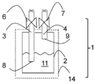
도 1은 Co-함유 막 형성 조성물 전달 장치(1)의 일 구현예의 측단면도이다.
도 2는 Co-함유 막 형성 조성물 전달 장치(1)의 제2 구현예의 측단면도이다.
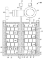
도 3은 고체 Co-함유 막 형성 조성물을 승화시키기 위한 고체 전구체 승화기(100)의 예시적 구현예의 측단면도이다.
도 4는 Co[N(SiMe3)2]2(THF), Co[N(SiMe2Et)2]2(THF), Co[N(SiMe3)2]2(py), Co[N(SiMe3)2]2(NMe2Et), Co[N(SiMe3)2]2(NMeEt2), Co[N(SiMe3)2]2(NEt3), Co[N(SiMe3)2]2(Me-피롤리딘), 및 Co[N(SiMe2Et)2]2(NMe2Et)의 온도 증가에 따른 중량 손실의 백분율을 나타낸, 1010 mbar 하에서의 비교 개방 컵 열중량 측정 분석(TGA) 그래프이다.
도 5는 Co[N(SiMe2Et)2]2(THF), Co[N(SiMe3)2]2(py), Co[N(SiMe3)2]2(NMeEt2), Co[N(SiMe3)2]2(NEt3), Co[N(SiMe3)2]2(Me-피롤리딘), 및 Co[N(SiMe2Et)2]2(NMe2Et)의 온도 증가에 따른 중량 손실의 백분율을 나타낸, 20 mbar 하에서의 비교 개방 컵 TGA 그래프이다.
도 6은 안정성 시험 전 및 150℃에서 1주의 안정성 시험 후에, Co[N(SiMe3)2]2(py)의 온도 증가에 따른 중량 손실의 백분율을 나타낸 TGA 그래프이다.
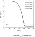
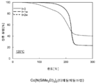
도 7은 안정성 시험 전 및 90℃에서 1주, 2주, 및 3주, 및 1개월 및 2개월의 안정성 시험 후에, Co[N(SiMe3)2]2(NMe2Et)의 온도 증가에 따른 중량 손실의 백분율을 나타낸 TGA 그래프이다.
도 8은 안정성 시험 전 및 80℃에서 1주, 2주, 및 3주의 안정성 시험 후에, Co[N(SiMe3)2]2(NMeEt2)의 온도 증가에 따른 중량 손실의 백분율을 나타낸 TGA 그래프이다.
도 9는 안정성 시험 전 및 110℃에서 1주 및 2주의 안정성 시험 후에, Co[N(SiMe3)2]2(1-Me-피롤리딘)의 온도 증가에 따른 중량 손실의 백분율을 나타낸 TGA 그래프이다.
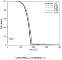
도 10은 안정성 시험 전 및 120℃에서 1주 및 2주의 안정성 시험 후에, Co[N(SiMe2Et)2]2(NMe2Et)의 온도 증가에 따른 중량 손실의 백분율을 나타낸 TGA 그래프이다.For a further understanding of the nature and objects of the present invention, reference will now be made to the following detailed description, taken in conjunction with the accompanying drawings, in which like elements are provided with like or similar reference numerals.
1 is a side cross-sectional view of one embodiment of a Co-containing film forming
2 is a side cross-sectional view of a second embodiment of the Co-containing film forming
3 is a side cross-sectional view of an exemplary embodiment of a
4 is a Co [N (SiMe 3) 2 ] 2 (THF), Co [N (
5 is a Co [N (SiMe 2 Et) 2] 2 (THF), Co [N (SiMe 3) 2] 2 (py), Co [N (SiMe 3) 2] 2 (NMeEt 2), Co [N (SiMe 3) 2] 2 ( NEt 3), Co [N (SiMe 3) 2] 2 (Me- pyrrolidine), and Co [N (SiMe 2 Et) 2] temperature increase of 2 (NMe 2 Et) Lt; RTI ID = 0.0 > 20 mbar, < / RTI >
6 is a TGA graph showing the percentage of weight loss due to temperature increase of Co [N (SiMe 3 ) 2 ] 2 (py) before and after one week's stability test at 150 ° C.
FIG. 7 shows the temperature increase of Co [N (SiMe 3 ) 2 ] 2 (NMe 2 Et) after a stability test at 1, 2, and 3 weeks, Lt; RTI ID = 0.0 > TGA < / RTI >
FIG. 8 is a TGA graph showing the percentage of weight loss due to temperature increase of Co [N (SiMe 3 ) 2 ] 2 (NMeEt 2 ) after 1, 2, to be.
9 is a graph showing the percentage of weight loss due to temperature increase of Co [N (SiMe 3 ) 2 ] 2 (1-Me-pyrrolidine) before and after 1 week and 2 weeks of stability test at 110 ° C. Graph.
10 is a TGA graph showing the percentage of weight loss due to temperature increase of Co [N (SiMe 2 Et) 2 ] 2 (NMe 2 Et) before stability test and at 120 ° C after one week and two weeks of stability test.
하기 화학식을 갖는 실릴아미드-함유 전구체를 포함하는 Co-함유 막 형성 조성물이 개시된다:A Co-containing film forming composition comprising a silylamide-containing precursor having the formula:
[화학식 I](I)
[화학식 II]≪ RTI ID = 0.0 &
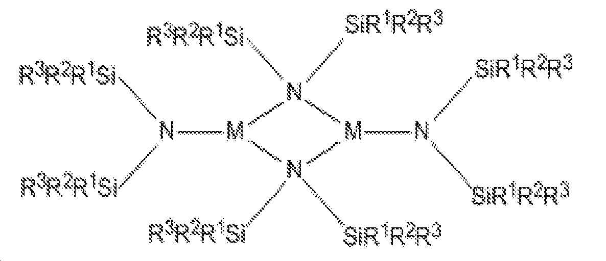
(상기 식에서, M은 Co이며; 각 R1, R2 및 R3은 독립적으로 수소(H) 또는 C1-C4 탄화수소로부터 선택되며; L은 피리딘, NMe3, NEt3, NMe2Et, NMeEt2, 1-Me-피롤리딘, 또는 PMe3으로부터 선택된 하나 또는 두 개의 중성 부가물이며; R1 및 R2, 또는 R2 및 R3은 결합되어 환형 규소-함유 헤테로사이클을 형성할 수 있음). 각 R1, R2 및 R3은 바람직하게, 독립적으로 메틸, 에틸, 이소프로필, n-프로필, n-부틸, 또는 t-부틸이다.NMe 3 , NEt 3 , NMe 2 Et, NMeEt 2 (wherein, M is Co and each R 1 , R 2 and R 3 are independently selected from hydrogen (H) or C 1 -
화학식 I을 갖는 예시적인 실릴아미드-함유 전구체는 Co[N(SiMe3)2]2(py); Co[N(SiMe3)2]2(Me3N); Co[N(SiMe3)2]2(Et3N); Co[N(SiMe3)2]2(Me2EtN); Co[N(SiMe3)2]2(MeEt2N); Co[N(SiMe3)2]2(1-Me-피롤리딘); Co[N(SiMe3)2]2(PMe3); Co[N(SiMe2Et)2]2(py); Co[N(SiMe2Et)2]2(Me3N); Co[N(SiMe2Et)2]2(Et3N); Co[N(SiMe2Et)2]2(Me2EtN); Co[N(SiMe2Et)2]2(MeEt2N); Co[N(SiMe2Et)2]2(1-Me-피롤리딘); Co[N(SiMe2Et)2]2(PMe3); 및 이들의 조합을 포함한다.Exemplary silylamide-containing precursors having Formula I include Co [N (SiMe 3 ) 2 ] 2 (py); Co [N (SiMe 3) 2 ] 2 (Me 3 N); Co [N (SiMe 3) 2 ] 2 (Et 3 N); Co [N (SiMe 3 ) 2 ] 2 (Me 2 EtN); Co [N (SiMe 3) 2 ] 2 (MeEt 2 N); Co [N (SiMe 3) 2 ] 2 (1-Me- pyrrolidine); Co [N (SiMe 3) 2 ] 2 (PMe 3); Co [N (SiMe 2 Et) 2 ] 2 (py); Co [N (SiMe 2 Et) 2] 2 (Me 3 N); Co [N (SiMe 2 Et) 2] 2 (Et 3 N); Co [N (SiMe 2 Et) 2 ] 2 (Me 2 EtN); Co [N (SiMe 2 Et) 2 ] 2 (MeEt 2 N); Co [N (SiMe 2 Et) 2] 2 (1-Me- pyrrolidine); Co [N (SiMe 2 Et) 2 ] 2 (PMe 3 ); And combinations thereof.
화학식 II를 갖는 예시적인 실릴아미드-함유 전구체는 {Co[N(SiMe3)2]2}2; {Co[N(SiMe2Et)2]2}2; 및 이들의 조합을 포함한다.An exemplary silylamide-containing precursor having the formula (II) is {Co [N (SiMe 3 ) 2 ] 2 } 2 ; {Co [N (SiMe 2 Et ) 2] 2} 2; And combinations thereof.
실릴아미드-함유 전구체는 테트라히드로푸란(THF), 에테르, 펜탄, 시클로헥산, 헥산, 헵탄, 또는 톨루엔과 같은 용매 중에서 CoX2(여기서, X는 Cl, Br, 또는 I임)를 M(N(SiR1R2R3)2)(여기서, M은 Li, Na, 또는 K임)과 반응시킴으로써 합성될 수 있다. 용매는 제거될 수 있으며, 화학식 I 또는 화학식 II의 생성물은 여과 및/또는 승화를 이용하여 염 부산물로부터 단리된다. 화학식 I의 L=THF 부가물은 THF-함유 전구체의 펜탄, 헵탄, 헥산 또는 시클로헥산과 같은 알칸 용액에 양성자화된 형태의 요망되는 리간드를 첨가하고, 생성물을 추출함으로써 치환될 수 있다. 추가 세부사항은 하기 실시예에서 제공된다.Silyl amide-containing precursors include tetrahydrofuran (THF), ether, pentane, cyclohexane, hexane, heptane, or a solvent such as toluene CoX 2 (wherein, X is Cl, Br, or I Im) M (N ( SiR 1 R 2 R 3 ) 2 ) (wherein M is Li, Na, or K). The solvent can be removed and the product of formula I or II is isolated from the salt by-product using filtration and / or sublimation. The L = THF adducts of formula (I) may be substituted by adding the desired ligand in the form of a protonated form of the THF-containing precursor to an alkane solution such as pentane, heptane, hexane or cyclohexane and extracting the product. Additional details are provided in the following examples.
공정 신뢰성을 보장하기 위하여, 개시된 Co-함유 막 형성 조성물은 사용하기 전에 연속 또는 분별 배치 증류, 재결정화, 또는 승화에 의해 대략 95% w/w 내지 대략 100% w/w 범위, 바람직하게, 대략 98% w/w 내지 대략 100% w/w 범위의 순도까지 정제될 수 있다. Co-함유 막 형성 조성물은 순도가 대략 99% w/w 내지 대략 100% w/w 범위일 때 본질적으로 실릴아미드-함유 전구체로 이루어진다. 당업자는, 순도가 H NMR, 또는 질량 분광법과 함께 가스 또는 액체 크로마토그래피에 의해 결정될 수 있음을 인식할 것이다. Co-함유 막 형성 조성물은 임의의 하기 불순물을 함유할 수 있다: 할라이드, 알칼리 금속, 알킬 아민, 알킬아미노-치환된 실란, 피리딘, 1-메틸피롤리딘, 피롤리딘, THF, 에테르, 펜탄, 시클로헥산, 헵탄, 톨루엔, 할로겐화된 금속 화합물. 바람직하게, 이러한 불순물의 총량은 0.1% w/w 미만이다. 정제된 조성물은 재결정화, 승화, 증류에 의해 및/또는 4 Å 분자체와 같은, 적합한 흡착제에 가스 또는 액체를 통과시킴으로써 생성될 수 있다.In order to ensure process reliability, the disclosed Co-containing film forming compositions may be applied in a range of about 95% w / w to about 100% w / w, preferably about 100% w / w by continuous or fractional batch distillation, recrystallization, Can be purified to a purity ranging from 98% w / w to about 100% w / w. The Co-containing film forming composition consists essentially of a silylamide-containing precursor when the purity ranges from about 99% w / w to about 100% w / w. One of skill in the art will recognize that purity can be determined by gas or liquid chromatography along with 1 H NMR, or mass spectrometry. The Co-containing film forming composition may contain any of the following impurities: halide, alkali metal, alkylamine, alkylamino-substituted silane, pyridine, 1-methylpyrrolidine, pyrrolidine, THF, , Cyclohexane, heptane, toluene, halogenated metal compounds. Preferably, the total amount of such impurities is less than 0.1% w / w. The purified composition may be produced by passing a gas or liquid through a suitable adsorbent, such as by recrystallization, sublimation, distillation and / or 4 A molecular sieves.
정제된 Co-함유 막 형성 조성물에서, THF, 에테르, 펜탄, 시클로헥산, 헵탄, 및/또는 톨루엔과 같은 각 용매의 농도는 대략 0% w/w 내지 대략 5% w/w, 바람직하게, 대략 0% w/w 내지 대략 0.1% w/w 범위일 수 있다. 용매는 Co-함유 막 형성 조성물의 합성에서 사용될 수 있다. 조성물로부터 용매의 분리는 둘 모두가 유사한 비등점을 갖는 경우에 어려울 수 있다. 혼합물의 냉각은 액체 용매에서 고체 전구체를 생성시킬 수 있으며, 이는 여과에 의해 분리될 수 있다. 진공 증류가 또한 사용될 수 있으며, 단, 조성물은 대략 이의 분해점보다 높게 가열되지 않는다.In a refined Co-containing film forming composition, the concentration of each solvent such as THF, ether, pentane, cyclohexane, heptane, and / or toluene is from about 0% w / w to about 5% w / w, 0% w / w to about 0.1% w / w. Solvents may be used in the synthesis of Co-containing film forming compositions. Separation of the solvent from the composition may be difficult if both have similar boiling points. Cooling of the mixture can produce a solid precursor in a liquid solvent, which can be separated by filtration. Vacuum distillation can also be used, provided that the composition is not heated above its decomposition point.
개시된 Co-함유 막 형성 조성물은 5% v/v 미만, 바람직하게, 1% v/v 미만, 더욱 바람직하게, 0.1% v/v 미만, 및 더욱더 바람직하게, 0.01% v/v 미만의 임의의 이의 유사체 또는 다른 반응 산물을 함유한다. 이러한 구현예는 보다 양호한 공정 반복성을 제공할 수 있다. 이러한 구현예는 Co-함유 막 형성 조성물의 증류에 의해 생성될 수 있다.The disclosed Co-containing film-forming compositions may contain any of less than 5% v / v, preferably less than 1% v / v, more preferably less than 0.1% v / v and even more preferably less than 0.01% v / Its analog or other reaction product. This embodiment can provide better process repeatability. This embodiment can be produced by distillation of the Co-containing film forming composition.
대안적으로, 특히, 혼합물이 개선된 공정 파라미터를 제공하거나 타겟 화합물의 단리가 너무 어렵거나 고가일 때, 개시된 Co-함유 막 형성 조성물은 대략 5% w/w 내지 대략 50% w/w의 하나의 화합물을 포함할 수 있으며, 조성물의 잔부는 제2 화합물을 포함한다. 예를 들어, 개시된 Co-함유 막 형성 조성물은 40/60% w/w의 Co[N(SiMe3)2]2(NMe2Et) 및 Co[N(SiMe3)2]2(NMeEt2)일 수 있다. 혼합물은 증기 증착에 적합한 안정한 액체 조성물을 생성할 수 있다.Alternatively, particularly when the mixture provides improved process parameters or the isolation of the target compound is too difficult or expensive, the disclosed Co-containing film forming composition may contain from about 5% w / w to about 50% w / w, And the remainder of the composition comprises the second compound. For example, the disclosed Co- film-forming composition containing 40 / of 60% w / w Co [N (SiMe 3) 2] 2 (
정제된 Co-함유 막 형성 조성물에서 미량 금속 및 메탈로이드의 농도는 각각 독립적으로 대략 0 ppbw 내지 대략 100 ppbw, 및 더욱 바람직하게, 대략 0 ppbw 내지 대략 10 ppbw 범위일 수 있다. 이러한 금속 또는 메탈로이드 불순물은 알루미늄(Al), 비소(As), 바륨(Ba), 베릴륨(Be), 비스무트(Bi), 카드뮴(Cd), 칼슘(Ca), 크롬(Cr), 구리(Cu), 갈륨(Ga), 게르마늄(Ge), 하프늄(Hf), 지르코늄(Zr), 인듐(In), 철(Fe), 납(Pb), 리튬(Li), 마그네슘(Mg), 망간(Mn), 텅스텐(W), 니켈(Ni), 포타슘(K), 소듐(Na), 스트론튬(Sr), 토륨(Th), 주석(Sn), 티타늄(Ti), 우라늄(U), 바나듐(V) 및 아연(Zn)을 포함하지만, 이로 제한되지 않는다. 정제된 Co-함유 막 형성 조성물에서 X(여기서, X는 Cl, Br임)의 농도는 대략 0 ppmw 내지 대략 100 ppmw, 및 더욱 바람직하게, 대략 0 ppmw 내지 대략 10 ppmw의 범위일 수 있다.The concentration of trace metals and metalloids in the purified Co-containing film forming composition may each independently range from about 0 ppbw to about 100 ppbw, and more preferably from about 0 ppbw to about 10 ppbw. Such metal or metalloid impurities may be aluminum, arsenic, barium, beryllium, bismuth, cadmium, calcium, chromium, copper, ), Gallium (Ga), germanium (Ge), hafnium (Hf), zirconium (Zr), indium (In), iron (Fe), lead (Pb), lithium (Li), magnesium ), Tungsten (W), nickel (Ni), potassium (K), sodium (Na), strontium (Sr), thorium (Sn), titanium (Ti), uranium ), And zinc (Zn). In the refined Co-containing film forming composition, the concentration of X (where X is Cl, Br) can range from about 0 ppmw to about 100 ppmw, and more preferably from about 0 ppmw to about 10 ppmw.
개시된 Co-함유 막 형성 조성물의 물에 대한 노출이 실릴아민-함유 전구체의 분해를 초래할 수 있기 때문에, 이를 방지하는 것을 주의해야 한다.It should be noted that exposure to water of the disclosed Co-containing film forming composition may result in decomposition of the silylamine-containing precursor, thereby preventing this.
또한, 증기 증착 방법을 위한 개시된 Co-함유 막 형성 조성물을 사용하는 방법이 개시된다. 개시된 방법은 코발트-함유 막의 증착을 위한 Co-함유 막 형성 조성물의 용도를 제공한다. 개시된 방법은 반도체, 광전지, LCD-TFT, 평판 타입 디바이스, 내화물 또는 항공기의 제작에서 유용할 수 있다.Also disclosed is a method of using the disclosed Co-containing film forming composition for a vapor deposition process. The disclosed process provides the use of a Co-containing film forming composition for the deposition of a cobalt-containing film. The disclosed method may be useful in the fabrication of semiconductors, photovoltaic cells, LCD-TFTs, flat panel devices, refractories or aircraft.
기판 상에 코발트-함유 층을 형성하는 개시된 방법은 반응기에 기판을 배치하고, 반응기에 개시된 Co-함유 막 형성 조성물의 증기를 전달하고, 증기를 기판과 접촉시켜(그리고 통상적으로 증기를 기판으로 유도하여) 기판의 표면 상에 코발트-함유 층을 형성하는 것을 포함한다.The disclosed method of forming a cobalt-containing layer on a substrate includes placing the substrate in a reactor, delivering the vapor of the Co-containing film forming composition disclosed in the reactor, contacting the vapor with the substrate (and typically introducing the vapor into the substrate Thereby forming a cobalt-containing layer on the surface of the substrate.
방법은 증기 증착 공정을 이용하여, 및 더욱 상세하게, CoMNx 막(여기서, x는 1 내지 4이며, M은 Ti, Ta, Mn, Al, 란탄족 원소(예를 들어, Er), 또는 이들의 조합임)의 증착을 위해 기판 상에 이중금속-함유 층을 형성시키는 것을 포함할 수 있다. 개시된 방법은 반도체, 광전지, LCD-TFT, 또는 평판 타입 디바이스의 제작에서 유용할 수 있다. H2, 또는 질소 공급원, 예를 들어, N2, NH3, 히드라진, 아민, 이들의 N 라디칼, 및 이들의 조합, 바람직하게, NH3 또는 플라즈마 처리된 N2가 또한 반응기내로 도입될 수 있다.The method is performed using a vapor deposition process and more particularly a CoMN x film wherein x is 1 to 4 and M is selected from the group consisting of Ti, Ta, Mn, Al, lanthanide elements (e.g., Er) Lt; RTI ID = 0.0 > a < / RTI > dual metal-containing layer on a substrate for deposition. The disclosed method may be useful in the fabrication of semiconductors, photovoltaic cells, LCD-TFTs, or flat panel type devices. H 2 or a nitrogen source such as N 2 , NH 3 , hydrazine, amines, N radicals thereof, and combinations thereof, preferably NH 3 or plasma-treated N 2 can also be introduced into the reactor have.
개시된 Co-함유 막 형성 조성물은 당업자에게 공지된 임의의 증착 방법을 이용하여 코발트-함유 막을 증착시키기 위해 사용될 수 있다. 적합한 증착 방법의 예는 화학적 증기 증착(CVD) 또는 원자층 증착(ALD)을 포함한다. 예시적인 CVD 방법은 열적 CVD, 펄스식 CVD(PCVD), 저압 CVD(LPCVD), 부기압 CVD(SACVD) 또는 대기압 CVD(APCVD), 고온-와이어 CVD(HWCVD, 또한 cat-CVD로서 알려짐, 여기서, 고온 와이어는 증착 공정을 위한 에너지원으로서 역할을 함), 라디칼 도입된 CVD, 유동성 PECVD를 포함하지만 이로 제한되지 않는 플라즈마 강화 CVD(PECVD) 및 이들의 조합을 포함한다. 예시적인 ALD 방법은 열적 ALD, 플라즈마 강화 ALD(PEALD), 공간적 격리 ALD, 고온-와이어 ALD(HWALD), 라디칼 도입된 ALD, 및 이들의 조합을 포함한다. 초임계 유체 증착이 또한 사용될 수 있다. 증착 방법은 적합한 단차 피복 및 막 두께 조절을 제공하기 위해 바람직하게 ALD, PE-ALD 또는 공간적 ALD이다.The disclosed Co-containing film forming compositions can be used to deposit a cobalt-containing film using any deposition method known to those skilled in the art. Examples of suitable deposition methods include chemical vapor deposition (CVD) or atomic layer deposition (ALD). Exemplary CVD methods are known as thermal CVD, pulsed CVD (PCVD), low pressure CVD (LPCVD), negative pressure CVD (SACVD) or atmospheric pressure CVD (APCVD), HWCVD, also known as cat- High temperature wire serves as an energy source for the deposition process), plasma enhanced CVD (PECVD) including, but not limited to, radical introduced CVD, flowable PECVD, and combinations thereof. Exemplary ALD methods include thermal ALD, plasma enhanced ALD (PEALD), spatially isolated ALD, high temperature-wire ALD (HWALD), radical introduced ALD, and combinations thereof. Supercritical fluid deposition may also be used. The deposition method is preferably ALD, PE-ALD or spatial ALD to provide suitable step coverage and film thickness control.
Co-함유 막 형성 조성물의 증기가 발생되고, 이후에, 기판을 포함한 반응 챔버내에 도입된다. 반응 챔버에서의 온도 및 압력, 및 기판의 온도는 기판 상에 실릴아민-함유 전구체의 적어도 일부의 증기 증착에 적합한 조건에서 유지된다. 다시 말해서, 반응 챔버내에 증기화된 조성물의 도입 후에, 반응 챔버 내의 조건은 전구체의 적어도 일부가 Co-함유 층을 형성하기 위해 기판 상에 증착되도록 조정된다. 당업자는 "전구체의 적어도 일부가 증착된다"가 전구체의 일부 또는 모두가 기판과 반응하거나 기판에 접착함을 의미한다는 것을 인식할 것이다. 본원에서, Co-함유 층의 형성에 도움을 주기 위해 반응물이 사용될 수도 있다.A vapor of the Co-containing film forming composition is generated and then introduced into the reaction chamber containing the substrate. The temperature and pressure in the reaction chamber and the temperature of the substrate are maintained under conditions suitable for vapor deposition of at least a portion of the silylamine-containing precursor on the substrate. In other words, after introduction of the vaporized composition into the reaction chamber, the conditions in the reaction chamber are adjusted so that at least a portion of the precursor is deposited on the substrate to form a Co-containing layer. Those skilled in the art will recognize that "at least a portion of the precursor is deposited" means that some or all of the precursor reacts with or adheres to the substrate. In the present application, a reactant may be used to assist in the formation of the Co-containing layer.
반응 챔버는 디바이스의 임의의 인클로져(enclosure) 또는 챔버일 수 있으며, 여기서, 증착 방법은 예를 들어, 비제한적으로, 평행판 타입 반응기, 냉각벽 타입 반응기, 고온벽 타입 반응기, 단일 웨이퍼 반응기, 다중 웨이퍼 반응기, 또는 다른 이러한 타입의 증착 시스템에서 일어난다. 이러한 예시적 반응 챔버 모두는 ALD 또는 CVD 반응 챔버로서 역할을 할 수 있다. 반응 챔버는 모든 ALD 및 부기압 CVD를 위해 약 0.5 mTorr 내지 약 20 Torr 범위의 압력에서 유지될 수 있다. 부기압 CVD 및 대기압 CVD 압력은 최대 760 Torr(대기압)의 범위일 수 있다. 또한, 반응 챔버 내의 온도는 약 20℃ 내지 약 600℃의 범위일 수 있다. 당업자는 요망되는 결과를 달성하기 위해 단순한 실험을 통해 온도가 최적화될 수 있다는 것을 인식할 것이다.The reaction chamber may be any enclosure or chamber of a device where the deposition method may be, for example but not limited to, a parallel plate type reactor, a cooling wall type reactor, a high temperature wall type reactor, a single wafer reactor, Wafer reactor, or other such type of deposition system. All of these exemplary reaction chambers may serve as ALD or CVD reaction chambers. The reaction chamber may be maintained at a pressure ranging from about 0.5 mTorr to about 20 Torr for all ALD and subatmospheric CVD. The negative pressure CVD and atmospheric pressure CVD pressures may be in the range of up to 760 Torr (atmospheric pressure). In addition, the temperature in the reaction chamber may range from about 20 캜 to about 600 캜. Those skilled in the art will recognize that the temperature may be optimized through simple experimentation to achieve the desired result.
반응기의 온도는 기판 홀더의 온도를 조절하거나 반응기 벽의 온도를 조절함으로써 조절될 수 있다. 기판을 가열하기 위해 사용되는 디바이스는 당해 분야에 알려져 있다. 반응기 벽은 충분한 성장률로 그리고 요망되는 물리적 상태 및 조성을 갖는 요망되는 막을 얻기 위해 충분한 온도까지 가열된다. 반응기 벽이 가열될 수 있는 비제한적인 예시적인 온도 범위는 대략 20℃ 내지 대략 600℃를 포함한다. 플라즈마 증착 공정이 사용될 때, 증착 온도는 대략 20℃ 내지 대략 550℃의 범위일 수 있다. 대안적으로, 열적 공정이 수행될 때, 증착 온도는 대략 300℃ 내지 대략 600℃의 범위일 수 있다.The temperature of the reactor can be adjusted by adjusting the temperature of the substrate holder or by controlling the temperature of the reactor wall. Devices used to heat the substrate are known in the art. The reactor walls are heated to a temperature sufficient to achieve the desired film with sufficient growth rate and desired physical state and composition. A non-limiting exemplary temperature range in which the reactor wall can be heated includes from about 20 占 폚 to about 600 占 폚. When a plasma deposition process is used, the deposition temperature may range from about 20 [deg.] C to about 550 [deg.] C. Alternatively, when a thermal process is performed, the deposition temperature may range from about 300 캜 to about 600 캜.
대안적으로, 기판은 충분한 성장률로 그리고 요망되는 물리적 상태 및 조성을 갖는 요망되는 코발트-함유 막을 얻기 위해 충분한 온도까지 가열될 수 있다. 기판이 가열될 수 있는 비제한적인 예시적인 온도 범위는 150℃ 내지 600℃를 포함한다. 바람직하게, 기판의 온도는 500℃ 이하로 유지된다.Alternatively, the substrate can be heated to a temperature sufficient to obtain a desired cobalt-containing film with a sufficient growth rate and desired physical state and composition. A non-limiting exemplary temperature range in which the substrate can be heated includes 150 deg. C to 600 deg. Preferably, the temperature of the substrate is maintained at 500 DEG C or lower.
반응기는 막이 그 위에 증착될 하나 이상의 기판을 포함한다. 기판은 일반적으로 그 위에서 공정이 수행되는 물질로서 규정된다. 기판은 반도체, 광전지, 평판, 또는 LCD-TFT 디바이스 제작에서 사용되는 임의의 적합한 기판일 수 있다. 적합한 기판의 예는 웨이퍼, 예를 들어, 규소, 실리카, 유리, 또는 GaAs 웨이퍼를 포함한다. 웨이퍼는 이전 제작 단계로부터 그 위에 증착된 상이한 물질의 하나 이상의 층을 가질 수 있다. 예를 들어, 웨이퍼는 규소 층(결정질, 비정질, 다공성, 등), 산화규소 층, 질화규소 층, 산질화규소 층, 탄소 도핑된 산화규소(SiCOH) 층, 또는 이들의 조합을 포함할 수 있다. 추가적으로, 웨이퍼는 구리 층 또는 귀금속 층(예를 들어, 백금, 팔라듐, 로듐, 또는 금)을 포함할 수 있다. 층은 MIM, DRAM, 또는 FeRam 기술에서 유전체 물질(예를 들어, ZrO2 기반 물질, HfO2 기반 물질, TiO2 기반 물질, 희토류 옥사이드 기반 물질, 3원 옥사이드 기반 물질, 예를 들어, 스트론튬 루테늄 옥사이드[SRO], 등)으로서 또는 구리와 저-k 층 사이의 산소 배리어로서 사용되는 니트라이드-기반 막(예를 들어, TaN)으로부터 사용되는 옥사이드를 포함할 수 있다. 웨이퍼는 배리어 층, 예를 들어, 망간, 망간 옥사이드, 등을 포함할 수 있다. 플라스틱 층, 예를 들어, 폴리(3,4-에틸렌디옥시티오펜)폴리(스티렌설포네이트)[PEDOT:PSS]가 또한 사용될 수 있다. 층은 평평하거나 패터닝될 수 있다. 예를 들어, 층은 수소화된 탄소, 예를 들어, CHx(여기서, x는 0보다 크다)로 제조된 패터닝된 포토레지스트 막일 수 있다.The reactor includes one or more substrates onto which the film is to be deposited. The substrate is generally defined as the material on which the process is performed. The substrate may be any suitable substrate used in semiconductor, photovoltaic, flat panel, or LCD-TFT device fabrication. Examples of suitable substrates include wafers, for example, silicon, silica, glass, or GaAs wafers. The wafer may have one or more layers of different materials deposited thereon from a previous fabrication step. For example, the wafer may comprise a silicon layer (crystalline, amorphous, porous, etc.), a silicon oxide layer, a silicon nitride layer, a silicon oxynitride layer, a carbon doped silicon oxide (SiCOH) layer, or a combination thereof. Additionally, the wafer may comprise a copper layer or a noble metal layer (e.g., platinum, palladium, rhodium, or gold). Layer may be a dielectric material (e.g., a ZrO 2 -based material, a HfO 2 -based material, a TiO 2 -based material, a rare earth oxide-based material, a ternary oxide based material such as a strontium ruthenium oxide (E.g., [SRO], etc.) or a nitride-based film (e.g., TaN) used as an oxygen barrier between copper and a low-k layer. The wafer may comprise a barrier layer, for example, manganese, manganese oxide, and the like. Plastic layers such as poly (3,4-ethylenedioxythiophene) poly (styrenesulfonate) [PEDOT: PSS] may also be used. The layer may be flat or patterned. For example, the layer may be a patterned photoresist film made of hydrogenated carbon, e.g., CH x (where x is greater than zero).
개시된 공정은 웨이퍼 상에 직접적으로 또는 웨이퍼의 상부 상의 하나 또는 하나 초과(패터닝된 층이 기판을 형성할 때)의 층 상에 직접적으로 코발트-함유 층을 증착할 수 있다. 기판은 높은 종횡비를 갖는 비아 또는 트렌치(trench)를 포함하도록 패터닝될 수 있다. 예를 들어, 컨포멀 Co-함유 막, 예를 들어, CoSi2는 대략 20:1 내지 대략 100:1 범위의 종횡비를 갖는 관통 규소 비아(through silicon via; TSV) 상에 임의의 ALD 기술을 이용하여 증착될 수 있다. 또한, 당업자는 본원에서 사용되는 용어 "막" 또는 "층"이 표면 상에 놓여지거나 표면 위에 살포된 소정 두께의 일부 물질을 지칭하며 표면이 트렌치 또는 라인일 수 있음을 인식할 것이다. 명세서 및 청구범위 전반에 걸쳐, 웨이퍼 및 그 위의 임의의 관련된 층은 기판으로서 지칭된다. 그렇지만, 여러 경우에, 사용되는 바람직한 기판은 탄소-도핑된 SiO2, TaN, Ta, TiN, Cu, Ru, 및 Si 타입 기판, 예를 들어, 폴리규소 또는 결정질 규소 기판으로부터 선택될 수 있다.The disclosed process can deposit a cobalt-containing layer directly on a wafer or directly on one or more than one layer (when the patterned layer forms a substrate) on top of the wafer. The substrate may be patterned to include vias or trenches having a high aspect ratio. For example, a conformal Co-containing film, such as CoSi 2, may be formed using any ALD technique on a through silicon via (TSV) having an aspect ratio ranging from approximately 20: 1 to approximately 100: 1 . ≪ / RTI > It will also be appreciated by those skilled in the art that the term "film" or "layer" as used herein refers to some material of a certain thickness that is placed on or spread over a surface and that the surface can be a trench or line. Throughout the specification and claims, the wafer and any associated layers thereon are referred to as substrates. However, in many cases, the preferred substrate to be used may be selected from carbon-doped SiO 2 , TaN, Ta, TiN, Cu, Ru, and Si type substrates, for example, polysilicon or crystalline silicon substrates.
개시된 Co-함유 막 형성 조성물은 용매, 예를 들어, 톨루엔, 에틸 벤젠, 자일렌, 메시틸렌, 데칸, 도데칸, 옥탄, 헥산, 펜탄, 3차 아민, 아세톤, 테트라히드로푸란, 에탄올, 에틸메틸케톤, 1,4-디옥산, 등을 추가로 포함할 수 있다. 개시된 조성물은 용매 중에 다양한 농도로 존재할 수 있다. 예를 들어, 얻어진 농도는 대략 0.05 M 내지 대략 2 M 범위일 수 있다.The disclosed Co-containing film forming compositions can be prepared by reacting the corresponding Co-containing film forming composition with a solvent such as toluene, ethylbenzene, xylene, mesitylene, decane, dodecane, octane, hexane, pentane, tertiary amine, acetone, tetrahydrofuran, Ketones, 1,4-dioxane, and the like. The disclosed compositions may be present in the solvent at various concentrations. For example, the concentration obtained may range from about 0.05 M to about 2 M.
Co-함유 막 형성 조성물은 Co-함유 막 형성 조성물 전달 장치의 세 가지의 예시적인 구현예를 도시한 도 1 내지 도 3의 Co-함유 막 형성 조성물 전달 장치에 의해 반응기 또는 증기 증착 챔버로 전달될 수 있다.The Co-containing film forming composition is delivered to the reactor or the vapor deposition chamber by the Co-containing film forming composition delivery device of Figs. 1-3, showing three exemplary embodiments of the Co-containing film forming composition delivery device .
도 1은 Co-함유 막 형성 조성물 반응물 전달 장치(1)의 일 구현예의 측면도이다. 도 1에서, 개시된 Co-함유 막 형성 조성물(11)은 두 개의 도관, 즉, 유입구 도관(3) 및 유출구 도관(4)을 갖는 용기(2) 내에 함유된다. 반응물 분야의 당업자는 용기(2), 유입구 도관(3) 및 유출구 도관(4)이 상승된 온도 및 압력에서도 가스상 형태의 Co-함유 막 형성 조성물(11)이 빠져나가는 것을 방지하도록 제작된다는 것을 인식할 것이다.1 is a side view of one embodiment of a Co-containing film forming composition
전달 장치(1)의 유출구 도관(4)은 반응기(미도시됨)에 또는 전달 장치와 반응기 사이의 다른 구성요소, 예를 들어, 가스 캐비넷에 밸브(7)를 통해 유동적으로 연결된다. 바람직하게, 용기(2), 유입구 도관(3), 밸브(6), 유출구 도관(4), 및 밸브(7)는 316L EP 또는 304 스테인레스강으로 제조된다. 그러나, 당업자는 다른 비-반응성 물질이 또한, 본원의 교시에서 사용될 수 있다는 것을 인식할 것이다.The
도 1에서, 유입구 도관(3)의 단부(8)는 Co-함유 막 형성 조성물(11)의 표면 위에 위치되며, 유출구 도관(4)의 단부(9)는 Co-함유 막 형성 조성물(11)의 표면 아래에 위치된다. 이러한 구현예에서, Co-함유 막 형성 조성물(11)은 바람직하게, 액체 형태이다. 질소, 아르곤, 헬륨, 및 이들의 혼합물을 포함하지만, 이로 제한되지 않는 불활성 가스가 유입구 도관(3)내에 도입될 수 있다. 불활성 가스는, 액체 Co-함유 막 형성 조성물(11)이 유출구 도관(4)을 통해 그리고 반응기(미도시됨)로 강제로 이동되도록 전달 장치(2)에 압력을 가한다. 반응기는, 위에 막이 형성될 기판에 증기를 전달하기 위해, 헬륨, 아르곤, 질소 또는 이들의 혼합물과 같은 운반 가스를 사용하거나 사용하지 않으면서, 액체 Co-함유 막 형성 조성물(11)을 증기로 변형시키는 증기화기를 포함할 수 있다. 대안적으로, 액체 Co-함유 막 형성 조성물(10)은 제트 또는 에어로졸로서 웨이퍼 표면에 직접적으로 전달될 수 있다.The
도 2는 Co-함유 막 형성 조성물 전달 장치(1)의 제2 구현예의 측면도이다. 도 2에서, 유입구 도관(3)의 단부(8)는 Co-함유 막 형성 조성물(11)의 표면 아래에 위치되며, 유출구 도관(4)의 단부(9)는 Co-함유 막 형성 조성물(11)의 표면 위에 위치된다. 도 2는 또한, 선택적 가열 부재(14)를 포함하며, 이는 Co-함유 막 형성 조성물(11)의 온도를 증가시킬 수 있다. 일 구현예에서, Co-함유 막 형성 조성물(11)은 고체 또는 액체 형태일 수 있다. 질소, 아르곤, 헬륨, 및 이들의 혼합물을 포함하지만, 이로 제한되지 않는, 불활성 가스가, 유입구 도관(3)내에 도입된다. 불활성 가스는 Co-함유 막 형성 조성물(11)에 거품을 형성하고, 불활성 가스와 증기화된 Co-함유 막 형성 조성물(11)의 혼합물을 유출구 도관(4)에 그리고 반응기 상으로 운반한다. 운반 가스로의 버블링은 또한, Co-함유 막 형성 조성물에 존재하는 임의의 용해된 산소를 제거할 수 있다.2 is a side view of a second embodiment of the Co-containing film forming
도 1 및 도 2는 밸브(6) 및 밸브(7)를 포함한다. 당업자는 밸브(6) 및 밸브(7)가 각각 도관(3) 및 도관(4)을 통해 흐르도록 개방된 위치 또는 닫혀진 위치에 배치될 수 있다는 것은 인식할 것이다. 도 1 및 도 2에서의 전달 장치(1), 또는 존재하는 임의의 고체 또는 액체의 표면 위에서 종결하는 단일 도관을 갖는 보다 단순한 전달 장치는, Co-함유 막 형성 조성물(11)이 증기 형태인 경우에 또는 충분한 증기압이 고체/액체 상 위에 존재하는 경우에, 사용될 수 있다. 이러한 경우에, Co-함유 막 형성 조성물(11)은 도 1에서 밸브(6) 또는 도 2에서 밸브(7)를 단순하게 개방시킴으로써 도관(3) 또는 도관(4)을 통해 증기 형태로 전달된다. 전달 장치(1)는 예를 들어, 선택적 가열 부재(14)의 사용에 의해 Co-함유 막 형성 조성물(11)을 증기 형태로 전달하도록 충분한 증기압을 제공하기 위해 적합한 온도에서 유지될 수 있다.Figures 1 and 2 include a
도 1 및 도 2가 Co-함유 막 형성 조성물 전달 장치(1)의 두 개의 구현예를 도시하지만, 당업자는 유입구 도관(3) 및 유출구 도관(4) 둘 모두가 또한 본원의 개시내용으로부터 벗어나지 않으면서, Co-함유 막 형성 조성물(11)의 표면 위 또는 아래에 위치될 수 있다는 것을 인식할 것이다. 또한, 유입구 도관(3)은 충전 포트일 수 있다.Although Figures 1 and 2 illustrate two embodiments of the Co-containing film forming
고체 형태의 Co-함유 막 형성 조성물의 증기는 승화기를 이용하여 반응기로 전달될 수 있다. 도 3은 예시적인 승화기(100)의 일 구현예를 도시한 것이다. 승화기(100)는 용기(33)를 포함한다. 용기(33)는 실린더형 용기일 수 있거나, 대안적으로, 비제한적으로, 임의의 형상일 수 있다. 용기(33)는 비제한적으로, 스테인레스강, 니켈 및 이의 합금, 석영, 유리, 및 다른 화학적으로 양립 가능한 물질과 같은 물질로 구성된다. 특정 경우에, 용기(33)는 비제한적으로, 다른 금속 또는 금속 합금으로 구성된다. 특정 경우에, 용기(33)는 약 8 센티미터 내지 약 55 센티미터의 내부 직경, 및 대안적으로, 약 8 센티미터 내지 약 30 센티미터의 내부 직경을 갖는다. 당업자에 의해 이해되는 바와 같이, 대안적인 구성은 상이한 치수를 가질 수 있다.The vapor of the Co-containing film-forming composition in solid form can be transferred to the reactor using a sublimator. FIG. 3 illustrates one embodiment of an
용기(33)는 밀봉 가능한 상부(sealable top)(15), 밀봉 부재(18), 및 가스켓(20)을 포함한다. 밀봉 가능한 상부(15)는 외부 환경으로부터 용기(33)를 밀봉하도록 구성된다. 밀봉 가능한 상부(15)는 용기(33)에 대한 접근을 허용하도록 구성된다. 추가적으로, 밀봉 가능한 상부(15)는 용기(33)내로 도관이 통과하도록 구성된다. 대안적으로, 밀봉 가능한 상부(15)는 용기(33)내로 유체 흐름을 가능하게 하도록 구성된다. 밀봉 가능한 상부(15)는 용기(33)와 유체 접촉을 유지하기 위해 딥 튜브(dip tube)(92)를 포함하는 도관을 수용하고 이를 통과시키도록 구성된다. 제어 밸브(90) 및 피팅(fitting)(95)을 갖는 딥 튜브(92)는 운반 가스를 용기(33)내로 흐르게 하도록 구성된다. 특정 경우에, 딥 튜브(92)는 용기(33)의 중심축 아래로 연장된다. 또한, 밀봉 가능한 상부(15)는 유출구 튜브(12)를 포함하는 도관을 수용하고 이를 통과시키도록 구성된다. 운반 가스 및 Co-함유 막 형성 조성물의 증기는 유출구 튜브(12)를 통해 용기(33)로부터 제거된다. 유출구 튜브(12)는 제어 밸브(10) 및 피팅(5)을 포함한다. 특정 경우에, 유출구 튜브(12)는 운반 가스를 승화기(100)로부터 반응기로 유도하기 위해, 가스 전달 매니폴드에 유동적으로 결합된다.The
용기(33) 및 밀봉 가능한 상부(15)는 적어도 두 개의 밀봉 부재(18)에 의해, 대안적으로, 적어도 약 네 개의 밀봉 부재에 의해 밀봉된다. 특정 경우에, 밀봉 가능한 상부(15)는 적어도 약 8개의 밀봉 부재(18)에 의해 용기(33)에 밀봉된다. 당업자에 의해 이해되는 바와 같이, 밀봉 부재(18)는 밀봉 가능한 상부(15)를 용기(33)에 분리 가능하게 결합시키고, 가스켓(20)과 함께 내가스성 씰(gas resistant seal)을 형성한다. 밀봉 부재(18)는 용기(33)를 밀봉하기 위해 당업자에게 공지된 임의의 적합한 수단을 포함할 수 있다. 특정 경우에, 밀봉 부재(18)는 나비나사(thumbscrew)를 포함한다.The
도 3에 예시된 바와 같이, 용기(33)는 그 안에 배치된 적어도 하나의 디스크를 추가로 포함한다. 디스크는 고체 물질을 위한 선반, 또는 수평 지지체를 포함한다. 특정 구현예에서, 내부 디스크(30)는 용기(33) 내에 환형으로 배치되며, 이에 따라, 디스크(30)는 개구(31)를 형성하는, 외부 직경 또는 내부 직경 미만인 원주 또는 용기(33)의 원주를 포함한다. 외부 디스크(86)는 용기(33) 내에서 원주방향으로 배치되며, 이에 따라, 디스크(86)는 용기(33)의 내부 직경과 동일하거나, 대략 동일하거나, 일반적으로 이와 일치하는 외부 직경 또는 원주를 포함한다. 외부 디스크(86)는 디스크의 중심에 배치된 개구(87)를 형성한다. 복수의 디스크가 용기(33) 내에 배치된다. 디스크는 서로 번갈아 적층되며, 여기서, 내부 디스크(30, 34, 36, 44)는 용기 내에서 외부 디스크(62, 78, 82, 86)와 함께 서로 번갈아 수직으로 적층된다. 구현예에서, 내부 디스크(30, 34, 36, 44)는 환형으로 외측으로 연장되며, 외부 디스크(62, 78, 82, 86)는 환형으로 용기(33)의 중심 쪽으로 연장된다. 도 3의 구현예에 예시되는 바와 같이, 내부 디스크(30, 34, 36, 44)는 외부 디스크(62, 78, 82, 86)와 물리적으로 접촉하지 않는다.As illustrated in Figure 3, the
어셈블링된 승화기(100)는 정렬되고 결합된 지지 다리(support leg)(50), 내부 통로(51), 동심벽(40, 41, 42), 및 동심 슬롯(47, 48, 49)을 포함하는 내부 디스크(30, 34, 36, 44)를 포함한다. 내부 디스크(30, 34, 36, 44)는 수직으로 적층되고, 딥 튜브(92)에 대해 환형으로 배향된다. 추가적으로, 승화기는 외부 디스크(62, 78, 82, 86)를 포함한다. 도 3에 예시되는 바와 같이, 외부 디스크(62, 78, 82, 86)는 열을 용기(33)에서 디스크(62, 78, 82, 86)로 전도하기 위한 양호한 접촉을 위해 용기(33)에 단단히 고정되어야 한다. 바람직하게, 외부 디스크(62, 78, 82, 86)는 용기(33)의 내부 벽에 결합되거나, 이와 물리적으로 접촉한다.The assembled
예시되는 바와 같이, 외부 디스크(62, 78, 82, 86) 및 내부 디스크(30, 34, 36, 44)는 용기(33) 내측에 적층된다. 승화기(100)를 형성하기 위해 용기(33)에서 어셈블링될 때, 내부 디스크(30, 34, 36, 44)는 어셈블링된 외부 디스크들(62, 78, 82, 86) 사이에 외부 가스 통로(31, 35, 37, 45)를 형성한다. 또한, 외부 디스크(62, 78, 82, 86)는 내부 디스크(30, 34, 36, 44)의 지지 다리와 함께 내부 가스 통로(56, 79, 83, 87)를 형성한다. 내부 디스크(30, 34, 36, 44)의 벽(40, 41, 42)은 고체 전구체를 유지하기 위한 홈이 있는 슬롯(grooved slot)을 형성한다. 외부 디스크(62, 78, 82, 86)는 고체 전구체를 유지하기 위한 벽(68, 69, 70)을 포함한다. 어셈블리 동안, 고체 전구체는 내부 디스크(30, 34, 36, 44)의 환형 슬롯(47, 48, 49) 및 외부 디스크(62, 78, 82, 86)의 환형 슬롯(64, 65, 66)내에 로딩된다.As illustrated, the
약 1 센티미터 미만, 대안적으로, 약 0.5 센티미터 미만, 및 대안적으로, 약 0.1 센티미터 미만 크기의 고체 분말 및/또는 과립형 입자는 내부 디스크(30, 34, 36, 44)의 환형 슬롯(47, 48, 49) 및 외부 디스크(62, 78, 82, 86)의 환형 슬롯(64, 65, 66)내에 로딩된다. 고체 전구체는 환형 슬롯에서 고체의 균일한 분포를 위해 적합한 임의의 방법에 의해 각 디스크의 환형 슬롯내에 로딩된다. 적합한 방법은 비제한적으로, 직접 붓기(direct pour), 스쿠프(scoop) 이용, 깔때기 이용, 자동화된 측정된 전달, 및 가압된 전달을 포함한다. 고체 전구체 물질의 화학적 성질에 따라, 로딩은 밀봉된 환경에서 수행될 수 있다. 추가적으로, 밀봉된 박스에서 불활성 가스 대기 및/또는 가압은 이의 독성, 휘발성, 산화성, 및/또는 공기 민감성 고체에 대해 실행될 수 있다. 각 디스크는 용기(33)에 디스크를 셋팅한 후에 로딩될 수 있다. 더욱 바람직한 절차는 디스크를 용기(33)에 셋팅하기 전에 고체를 로딩하는 것이다. 승화기에 로딩된 고체 전구체의 총 중량은 로딩 공정 전 및 후에 승화기를 계량함으로써 기록될 수 있다. 또한, 소비되는 고체 전구체는 증기화 및 증착 공정 후 승화기를 계량함으로써 계산될 수 있다.Solid powder and / or granular particles having a size of less than about 1 centimeter, alternatively less than about 0.5 centimeter, and alternatively less than about 0.1 centimeter, are formed in the annular slot 47 of the
제어 밸브(90) 및 피팅(95)을 갖는 딥 튜브(92)는, 내부 디스크(30, 34, 36, 44)의 정렬되고 결합된 지지 다리의 중앙 통로(51)에 정위된다. 이에 따라, 딥 튜브(92)는 내부 통로(51)를 통해 용기(33)의 하부(58) 쪽으로 수직으로 진행한다. 딥 튜브 단부(55)는 가스 윈도우(52)에/또는 위에 용기의 하부(58)에 대해 근위에 배치된다. 가스 윈도우(52)는 하부 내부 디스크(44)에 배치된다. 가스 윈도우(52)는 딥 튜브(92) 밖으로 운반 가스 흐름을 허용하도록 구성된다. 어셈블링된 승화기(100)에서, 가스 통로(59)는 용기(33)의 하부 표면(58) 및 하부 내부 디스크(44)에 의해 형성된다. 특정 경우에, 가스 통로(59)는 운반 가스를 가열하도록 구성된다.
작동 시에, 운반 가스는 딥 튜브(92)를 통해 용기(33)내에 도입 전에 예열된다. 대안적으로, 운반 가스는 하부 표면(58)에 의해 가스 통로(59)를 통해 흐르는 동안에 가열될 수 있다. 하부 표면(58)은 본원의 교시와 일치하게 외부 가열기에 의해 열적으로 결합되고/거나 가열된다. 이후에, 운반 가스는 내부 디스크(44)의 외부 벽(42) 및 외부 디스크(62)의 외측 벽(61)에 의해 형성된 가스 통로(45)를 통해 진행한다. 가스 통로(45)는 내부 디스크(44)의 상부로 이어진다. 운반 가스는 환형 슬롯(47, 48 및 49)에 로딩된 고체 전구체의 상부에 걸쳐 연속적으로 흐른다. 환형 슬롯(47, 48, 49)으로부터의 승화된 고체 증기는 운반 가스와 혼합되고, 용기(33)를 통해 수직 상향으로 흘려 보낸다.In operation, the carrier gas is preheated prior to introduction into the
도 3이 임의의 고체 Co-함유 막 형성 조성물의 증기를 반응기로 전달할 수 있는 승화기의 일 구현예를 도시한 것이지만, 당업자는 본원의 교시로부터 벗어나지 않으면서, 다른 승화기 디자인이 또한 적합할 수 있다는 것을 인식할 것이다. 마지막으로, 당업자는 개시된 Co-함유 막 형성 조성물이 본원의 교시로부터 벗어나지 않으면서, WO 2006/059187호(Jurcik 등)에 개시된 앰플과 같은, 다른 전달 장치를 이용하여 반도체 가공 툴로 전달될 수 있다는 것을 인식할 것이다.While FIG. 3 illustrates one embodiment of a sublimator capable of transferring the vapor of any solid Co-containing film forming composition to a reactor, those skilled in the art will appreciate that other sublimator designs may also be suitable without departing from the teachings herein . Finally, those skilled in the art will appreciate that the disclosed Co-containing film forming compositions can be delivered to semiconductor processing tools using other delivery devices, such as an ampoule as disclosed in WO 2006/059187 (Jurcik et al.), Without departing from the teachings herein Will recognize.
필요한 경우에, 도 1 내지 도 3의 Co-함유 막 형성 조성물 디바이스는 Co-함유 막 형성 조성물이 이의 액체 상으로 존재하고 충분한 증기압을 갖게 하는 온도까지 가열될 수 있다. 전달 장치는 예를 들어, 0 내지 150℃ 범위의 온도에서 유지될 수 있다. 당업자는 전달 장치의 온도가 증기화된 Co-함유 막 형성 조성물의 양을 조절하기 위해 공지된 방식으로 조정될 수 있다는 것을 인식한다.If desired, the Co-containing film-forming composition device of Figs. 1-3 may be heated to a temperature such that the Co-containing film-forming composition is present in its liquid phase and has a sufficient vapor pressure. The delivery device may be maintained at a temperature in the range, for example, from 0 to 150 < 0 > C. Those skilled in the art will appreciate that the temperature of the delivery device can be adjusted in a known manner to control the amount of the vaporized Co-containing film forming composition.
개시된 전구체 이외에, 반응물이 또한 반응기내로 도입될 수 있다. 반응물은 산소, 예를 들어, O2, O3, H2O, H2O2 중 하나; 산소 함유 라디칼, 예를 들어, O· 또는 OH·, NO, NO2; 카르복실산, 예를 들어, 포름산, 아세트산, 프로피온산, NO, NO2 또는 카르복실산의 라디칼; 파라-포름알데하이드; 및 이들의 혼합물을 함유할 수 있다. 바람직하게, 산소-함유 반응물은 O2, O3, H2O, H2O2, 이들의 산소 함유 라디칼, 예를 들어, O· 또는 OH·, 및 이들의 혼합물로 이루어진 군으로부터 선택된다. 바람직하게, ALD 공정이 수행될 때, 반응물은 플라즈마 처리된 산소, 오존, 또는 이들의 조합이다. 산소-함유 반응물이 사용될 때, 얻어진 코발트 함유 막이 또한 산소를 함유할 것이다.In addition to the precursors disclosed, the reactants may also be introduced into the reactor. The reactant may be one of oxygen, e.g., O 2 , O 3 , H 2 O, H 2 O 2 ; Oxygen-containing radicals, e.g., O ·, or · OH, NO, NO 2; Radicals of carboxylic acids such as formic acid, acetic acid, propionic acid, NO, NO 2 or carboxylic acids; Para-formaldehyde; And mixtures thereof. Preferably, the oxygen-containing reactant is selected from the group consisting of O 2 , O 3 , H 2 O, H 2 O 2 , their oxygen containing radicals such as O · or OH ·, and mixtures thereof. Preferably, when an ALD process is performed, the reactants are plasma treated oxygen, ozone, or a combination thereof. When an oxygen-containing reactant is used, the resulting cobalt-containing film will also contain oxygen.
대안적으로, 반응물은 H2, NH3, (SiH3)3N, 히드리도실란(예를 들어, SiH4, Si2H6, Si3H8, Si4H10, Si5H10, Si6H12), 클로로실란 및 클로로폴리실란(예를 들어, SiHCl3, SiH2Cl2, SIH3Cl, Si2Cl6, Si2HCl5, Si3Cl8), 알킬실란(예를 들어, (CH3)2SiH2, (C2H5)2SiH2, (CH3)SiH3, (C2H5)SiH3), 히드라진(예를 들어, N2H4, MeHNNH2, MeHNNHMe), 유기 아민(예를 들어, N(CH3)H2, N(C2H5)H2, N(CH3)2H, N(C2H5)2H, N(CH3)3, N(C2H5)3, (SiMe3)2NH), 피라졸린, 피리딘, B-함유 분자(예를 들어, B2H6, 9-보라비시클로[3,3,1]논, 트리메틸보론, 트리에틸보론, 보라진), 알킬 금속(예를 들어, 트리메틸알루미늄, 트리에틸알루미늄, 디메틸아연, 디에틸아연), 알코올(예를 들어, 에탄올 또는 메탄올), 이들의 라디칼 종, 및 이들의 혼합물 중 하나일 수 있다. 바람직하게, 반응물은 H2, NH3, SiH4, Si2H6, Si3H8, SiH2Me2, SiH2Et2, N(SiH3)3, 에탄올, 이들의 수소 라디칼, 또는 이들의 혼합물이다. 바람직하게, 반응물은 SiHCl3, Si2Cl6, Si2HCl5, Si2H2Cl4, 및 시클로-Si6H6Cl6이다. 이러한 반응물이 사용될 때, 얻어진 Co-함유 막은 순수한 Co일 수 있다.Alternatively, the reactants can be H 2 , NH 3 , (SiH 3 ) 3 N, hydridosilane (eg, SiH 4 , Si 2 H 6 , Si 3 H 8 , Si 4 H 10 , Si 5 H 10 , Si 6 H 12 ), chlorosilanes and chloropolysilanes (e.g., SiHCl 3 , SiH 2 Cl 2 , SIH 3 Cl, Si 2 Cl 6 , Si 2 HCl 5 , Si 3 Cl 8 ) g., (CH 3) 2 SiH 2 , (C 2 H 5) 2
반응물은 반응물을 이의 라디칼 형태로 분해하기 위해 플라즈마에 의해 처리될 수 있다. N2 또한 플라즈마로 처리될 때 반응물로서 사용될 수 있다. 예를 들어, 플라즈마는 약 50 W 내지 약 500 W, 바람직하게, 약 100 W 내지 약 200 W 범위의 출력으로 발생될 수 있다. 플라즈마는 반응기 자체 내에서 발생되거나 존재할 수 있다. 대안적으로, 플라즈마는 일반적으로, 반응기로부터 제거된 위치에, 예를 들어, 원거리에 위치된 플라즈마 시스템에 존재할 수 있다. 당업자는 이러한 플라즈마 처리에 적합한 방법 및 장치를 인식할 것이다.The reactants may be treated by plasma to decompose the reactants into their radical forms. N 2 can also be used as a reactant when treated with a plasma. For example, the plasma may be generated at an output ranging from about 50 W to about 500 W, preferably from about 100 W to about 200 W. Plasma can be generated or present in the reactor itself. Alternatively, the plasma may generally be present at a location removed from the reactor, for example, in a plasma system located remotely. Those skilled in the art will recognize methods and apparatus suitable for such plasma processing.
개시된 Co-함유 막 형성 조성물은 또한, 할로실란 또는 폴리할로디실란, 예를 들어, 헥사클로로디실란, 펜타클로로디실란, 또는 테트라클로로디실란, 및 CoSi, CoSiCN, 또는 CoSiCOH 막을 형성시키기 위한 하나 이상의 반응물과 함께 사용될 수 있다.The disclosed Co-containing film-forming compositions may also include one or more of halo silane or polyhalosilane, such as hexachlorodisilane, pentaclorodisilane, or tetrachlorodisilane, and one for forming a CoSi, CoSiCN, or CoSiCOH film Can be used together with the above reactants.
요망되는 Co-함유 막이 또한 다른 원소, 예를 들어, 그리고 비제한적으로, Ti, Mn, Ta, Hf, Nb, Mg, Al, Sr, Y, Ba, Ca, As, Sb, Bi, Sn, Pb, 란탄족 원소(예를 들어, Er), 또는 이들의 조합을 함유할 때, 반응물은 알킬, 예를 들어, Ln(RCp)3, 알킬아민, 예를 들어, Ti(NEt2)4 또는 이들의 임의의 조합으로부터 선택되지만 이로 제한되지 않는 다른 전구체를 포함할 수 있다.The desired Co-containing film may also contain other elements such as, but not limited to, Ti, Mn, Ta, Hf, Nb, Mg, Al, Sr, Y, Ba, Ca, As, Sb, , lanthanides (e. g., Er), or when containing these combinations, the reagent is alkyl, such as, Ln (RCp) 3, alkyl amines, e.g., Ti (NEt 2) 4, or their But not limited to, < RTI ID = 0.0 > and / or < / RTI >
Co-함유 막 형성 조성물 및 하나 이상의 반응물은 동시에(예를 들어, CVD), 순차적으로(예를 들어, ALD), 또는 다른 조합으로 반응 챔버내에 도입될 수 있다. 예를 들어, Co-함유 막 형성 조성물은 하나의 펄스로 도입될 수 있으며, 두 개의 추가적인 반응물은 별도의 펄스로 함께 도입될 수 있다(예를 들어, 변형된 ALD). 대안적으로, 반응 챔버는 Co-함유 막 형성 조성물의 도입 전에 이미 반응물을 함유할 수 있다. 반응물은 국소화되거나 반응 챔버로부터 원거리에 있는 플라즈마 시스템을 통해 진행되고, 라디칼로 분해될 수 있다. 대안적으로, Co-함유 막 형성 조성물은 반응 챔버에 연속적으로 도입될 수 있으며, 다른 반응물이 펄스식으로 도입된다(예를 들어, 펄스화-CVD). 각 예에서, 펄스 이후에 도입되는 과량의 성분을 제거하기 위해 퍼지 또는 배기 단계가 이어질 수 있다. 각 예에서, 펄스는 약 0.01 s 내지 약 10 s, 대안적으로, 약 0.3 s 내지 약 3 s, 대안적으로, 약 0.5 s 내지 약 2 s 범위의 기간 동안 지속할 수 있다. 다른 대안으로, Co-함유 막 형성 조성물 및 하나 이상의 반응물은 수 개의 웨이퍼를 유지하는 서셉터가 회전되는 샤워 헤드로부터 동시에 살포될 수 있다(예를 들어, 공간적 ALD).The Co-containing film forming composition and the at least one reactant may be introduced into the reaction chamber at the same time (e.g., CVD), sequentially (e.g., ALD), or in other combinations. For example, a Co-containing film forming composition can be introduced in one pulse, and two additional reactants can be introduced together in separate pulses (e.g., ALD modified). Alternatively, the reaction chamber may already contain a reactant before introduction of the Co-containing film forming composition. The reactants may be localized or proceed through the plasma system remotely from the reaction chamber, and may be broken down into radicals. Alternatively, the Co-containing film forming composition can be continuously introduced into the reaction chamber, and other reactants are introduced in a pulsed manner (e.g., pulsed-CVD). In each example, a purge or evacuation step may be followed to remove excess components introduced after the pulse. In each example, the pulse may last for a period of time ranging from about 0.01 s to about 10 s, alternatively from about 0.3 s to about 3 s, alternatively from about 0.5 s to about 2 s. Alternatively, the Co-containing film forming composition and the at least one reactant may be simultaneously sprayed from the showerhead in which the susceptor holding several wafers is rotated (e.g., spatial ALD).
하나의 비제한적인 예시적 ALD 타입 공정에서, Co-함유 막 형성 조성물의 증기 상은 반응 챔버내에 도입되며, 여기서, 실릴아민-함유 전구체의 적어도 일부는 적합한 기판, 예를 들어, Si, SiO2, Al2O3, 등과 반응하여 흡착된 코발트 층을 형성한다. 과량의 조성물은 이후에, 반응 챔버를 퍼징하고/거나 배기함으로써 반응 챔버로부터 제거될 수 있다. 산소 공급원은 반응 챔버내에 도입되며, 여기서, 이는 자가-제한 방식으로 흡착된 코발트 층과 반응한다. 임의의 과량의 산소 공급원은 반응 챔버를 퍼징하고/거나 배기함으로써 반응 챔버로부터 제거된다. 요망되는 막이 코발트 옥사이드 막인 경우에, 이러한 2-단계 공정은 요망되는 막 두께를 제공할 수 있거나, 필요한 두께를 갖는 막이 얻어질 때까지 반복될 수 있다.In one non-limiting exemplary ALD type process, a vapor phase of a Co-containing film forming composition is introduced into a reaction chamber wherein at least a portion of the silylamine-containing precursor is a suitable substrate, such as Si, SiO 2 , Al 2 O 3 , etc. to form an adsorbed cobalt layer. Excess compositions may then be removed from the reaction chamber by purging and / or evacuating the reaction chamber. An oxygen source is introduced into the reaction chamber, where it reacts with the adsorbed cobalt layer in a self-limiting manner. Any excess oxygen source is removed from the reaction chamber by purging and / or evacuating the reaction chamber. If the desired film is a cobalt oxide film, this two-step process may provide the desired film thickness, or it may be repeated until a film with the required thickness is obtained.
대안적으로, 요망되는 막이 제2 구성요소(즉, CoMOx, 여기서, x는 1 내지 4일 수 있으며, M은 Ti, Ta, Hf, Nb, Mg, Al, Sr, Y, Ba, Ca, As, Sb, Bi, Sn, Pb, Co, 란탄족 원소(예를 들어, Er), 또는 이들의 조합임)를 함유하는 경우에, 상기 2-단계 공정 이후에, 반응 챔버내에 제2 전구체의 증기를 도입할 수 있다. 제2 전구체는 증착되는 막의 특성을 기반으로 하여 선택될 것이다. 반응 챔버내에 도입 후에, 제2 전구체는 기판과 접촉된다. 임의의 과량의 제2 전구체는 반응 챔버를 퍼징하고/거나 배기함으로써 반응 챔버로부터 제거된다. 다시 한번, N 공급원은 제2 전구체와 반응하기 위해 반응 챔버내에 도입될 수 있다. 과량의 N 공급원은 반응 챔버를 퍼징하고/거나 배기함으로써 반응 챔버로부터 제거된다. 요망되는 막 두께가 달성된 경우에, 공정이 종결될 수 있다. 그러나, 보다 두꺼운 막이 요망되는 경우에, 전체 4-단계 공정이 반복될 수 있다. Co-함유 막 형성 조성물, 제2 전구체, 및 N 공급원의 제공을 교대함으로써, 요망되는 조성 및 두께의 막이 증착될 수 있다.Alternatively, the desired film can be a second component (i.e., CoMO x , where x can be from 1 to 4, where M is selected from Ti, Ta, Hf, Nb, Mg, Al, Sr, Y, Wherein the second precursor is a precursor of the second precursor in the reaction chamber after the two-step process, when the precursor comprises As, Sb, Bi, Sn, Pb, Co, a lanthanide element (e.g. Er) Steam can be introduced. The second precursor will be selected based on the properties of the film being deposited. After introduction into the reaction chamber, the second precursor contacts the substrate. Any excess second precursor is removed from the reaction chamber by purging and / or evacuating the reaction chamber. Once again, the N source can be introduced into the reaction chamber to react with the second precursor. Excess N source is removed from the reaction chamber by purging and / or evacuating the reaction chamber. If the desired film thickness is achieved, the process can be terminated. However, if a thicker film is desired, the entire four-step process can be repeated. By alternating the provision of the Co-containing film forming composition, the second precursor, and the N source, a film of the desired composition and thickness can be deposited.
추가적으로, 펄스의 수를 변경시킴으로써, 요망되는 화학량론적 M:Co 비를 갖는 막이 얻어질 수 있다. 예를 들어, CoMN 막은 Co-함유 막 형성 조성물의 하나의 펄스 및 제2 전구체의 하나의 펄스를 가짐으로써 얻어질 수 있으며, 각 펄스 이후에 NH3 공급원의 펄스가 이어진다. 그러나, 당업자는 요망되는 막을 얻기 위해 요구되는 펄스의 수가 얻어진 막의 화학량론적 비율과 일치하지 않을 수 있다는 것을 인식할 것이다.Additionally, by varying the number of pulses, a film having the desired stoichiometric M: Co ratio can be obtained. For example, a CoMN film can be obtained by having one pulse of the Co-containing film forming composition and one pulse of the second precursor, followed by a pulse of the NH 3 source after each pulse. However, those skilled in the art will appreciate that the number of pulses required to obtain the desired film may not match the stoichiometric ratio of the film obtained.
상기에 논의된 공정으로부터 얻어진 코발트-함유 막은 Co, CoSi2, CoO2, CoN, CoMN, CoC, CoON, CoCN, CoCON, 또는 MCoOx를 포함할 수 있으며, 여기서, M은 Hf, Zr, Ti, Nb, Ta, 또는 Ge와 같은 원소이며, x는 M의 산화 상태에 따라 0 내지 4일 수 있다. 당업자는 적절한 Co-함유 막 형성 조성물 및 반응물의 공평한 선택에 의해, 요망되는 막 조성물이 얻어질 수 있다는 것을 인식할 것이다.The cobalt-containing film obtained from the process discussed above may include Co, CoSi 2 , CoO 2 , CoN, CoMN, CoC, CoON, CoCN, CoCON, or MCoO x , where M is Hf, Zr, Ti, Nb, Ta, or Ge, and x may be 0 to 4 depending on the oxidation state of M. Those skilled in the art will recognize that the desired film composition can be obtained by the proper choice of the appropriate Co-containing film forming composition and reactants.
요망되는 막 두께를 얻을 시에, 막은 열적 어닐링, 로-어닐링, 고속 열적 어닐링, UV 또는 e-빔 경화, 및/또는 플라즈마 가스 노출과 같은 추가 가공으로 처리될 수 있다. 당업자는 이러한 추가적인 가공 단계를 수행하기 위해 사용되는 시스템 및 방법을 인식한다. 예를 들어, 코발트-함유 막은 불활성 대기, H-함유 대기, N-함유 대기, O-함유 대기, 또는 이들의 조합 하에서, 대략 0.1초 내지 대략 7200초 범위의 시간 동안 대략 200℃ 내지 대략 1000℃ 범위의 온도에 노출될 수 있다. 가장 바람직하게, 온도는 H-함유 대기 하에서 3600초 미만 동안 600℃이다. 얻어진 막은 보다 적은 불순물을 함유할 수 있고, 이에 따라, 개선된 성능 특징을 가질 수 있다. 어닐링 단계는 증착 공정이 수행되는 동일한 반응 챔버에서 수행될 수 있다. 대안적으로, 기판은 반응 챔버로부터 제거될 수 있으며, 어닐링/플래시 어닐링 공정은 별도의 장치에서 수행된다. 임의의 상기 후-처리 방법, 특히 열적 어닐링은 코발트-함유 막의 탄소 및 질소 오염을 감소시키는 데 효과적인 것임을 발견하였다.Upon obtaining the desired film thickness, the film may be treated with further processing such as thermal annealing, low-annealing, rapid thermal annealing, UV or e-beam curing, and / or plasma gas exposure. Those skilled in the art will recognize the systems and methods used to perform these additional processing steps. For example, the cobalt-containing film may be heated to a temperature of from about 200 ° C to about 1000 ° C for a period of time ranging from about 0.1 seconds to about 7200 seconds under an inert atmosphere, an H-containing atmosphere, an N-containing atmosphere, an O- Lt; / RTI > range. Most preferably, the temperature is 600 [deg.] C for less than 3600 seconds under an H-containing atmosphere. The resulting film may contain less impurities and, therefore, may have improved performance characteristics. The annealing step may be performed in the same reaction chamber in which the deposition process is performed. Alternatively, the substrate may be removed from the reaction chamber and the annealing / flash annealing process is performed in a separate apparatus. It has been found that any such post-treatment method, in particular thermal annealing, is effective in reducing carbon and nitrogen contamination of the cobalt-containing film.
실시예Example
하기 비제한적인 실시예는 본 발명의 구현예를 추가로 예시하기 위해 제공된다. 그러나, 실시예는 모든 것을 포함하고자 의도된 것은 아니고, 본원에 기술된 본 발명의 범위를 제한하고자 의도된 것은 아니다.The following non-limiting examples are provided to further illustrate embodiments of the present invention. However, the embodiments are not intended to be all-inclusive and are not intended to limit the scope of the invention described herein.
실시예 1: Co[N(SiMe3)2]2(THF)의 합성 Example 1: Synthesis of Co [N (SiMe 3 ) 2 ] 2 (THF)
플라스크를 CoCl2(7.08 g) 및 THF(50 ml)로 채웠다. NaN(SiMe3)2 THF 용액(100 mL)을 -78℃에서 적가하고, 이후에, 혼합물을 실온(대략 23℃, RT)까지 가온시켰다. 실온에서 밤새 반응시킨 후에, 용액을 CeliteTM 브랜드 규조토를 통해 여과하고, 모든 용매를 진공 하에서 제거하였다. 연한 녹색 화합물을 진공(50 mTorr, 70 내지 80℃) 하에서 승화에 의해 정제하였다. 수율 58%. XRD 분석을 위하여, 생성물을 -30℃에서 헥산으로부터 재결정화하였다. 공기 민감한 밝은 녹색 결정을 수득하였다.The flask was charged with CoCl 2 (7.08 g) and THF (50 ml). A solution of NaN (SiMe 3 ) 2 in THF (100 mL) was added dropwise at -78 ° C, after which the mixture was allowed to warm to room temperature (approximately 23 ° C, RT). After reacting overnight at room temperature, the solution was filtered through Celite TM brand diatomaceous earth and all solvents were removed under vacuum. The light green compound was purified by sublimation under vacuum (50 mTorr, 70-80 C).
1H NMR (δ, C6D6) -16.98 (s) 96.91 (brs), DSC 58℃(융점), 183℃(분해), 108℃에서 증기압 1 Torr. 1 H NMR (δ, C 6 D 6) -16.98 (s) 96.91 (brs),
실시예 2: Co[N(SiMe2Et)2]2(THF)의 합성 Example 2: Synthesis of Co [N (SiMe 2 Et) 2 ] 2 (THF)
플라스크를 CoCl2 및 THF로 채웠다. NaN(SiMe2Et)2 THF 용액을 -78℃에서 적가하고, 이후에, 혼합물을 실온(대략 23℃, RT)까지 가온시켰다. 진한 녹색 액체를 수득하였다.The flask was charged with CoCl 2 and THF. A solution of NaN (SiMe 2 Et) 2 in THF was added dropwise at -78 ° C, after which the mixture was allowed to warm to room temperature (approximately 23 ° C, RT). A dark green liquid was obtained.
1H NMR (δ, C6D6) -34.69 (s), -19.67 (s) 2.11 (brs) 89.12 (brs), DSC 215℃(분해), 100℃에서 증기압 1 Torr. 1 H NMR (?, C 6 D 6 ) -34.69 (s), -19.67 (s) 2.11 (brs) 89.12 (brs), DSC 215 캜 (decomposition)
실시예 3: Co[N(SiMe3)2]2(부가물)의 합성 Example 3: Synthesis of Co [N (SiMe 3 ) 2 ] 2 (adduct)
10 당량의 부가물 리간드(건조된 피리딘(py.), 디메틸에틸아민, 디에틸메틸아민, 트리에틸아민, 1-메틸-피롤리딘)를 질소 하에서, 실시예 1과 유사하게 제조된, Co[N(SiMe3)2]2(THF)(1.0 g)의 헥산 용액(5 mL)에 적가하였다. 밤새 반응한 후에, 용매 및 과량의 부가물 리간드를 진공 하에서 제거하였다. 미정제 생성물을 건조 헥산으로 추출하고, PTFE 필터를 통해 여과하였다. 타겟화된 화합물을 -30℃에서 건조 헥산으로부터의 재결정화에 의해 정제하고, 진공 하, 실온에서 건조시켰다. 각 부가 화합물을 청색 내지 녹색 고체로서 단리하였다. 피리딘 부가물(연한 청색, y.78%), 디메틸에틸아민 부가물(청색, y.87%), 디에틸메틸아민 부가물(진한 녹색, y.56%), 트리에틸아민 부가물(진한 녹색, y.93%), 1-메틸-피롤리딘 부가물(연한 청색, y.86%).10 eq of the adduct ligand (dried pyridine (py.), Dimethylethylamine, diethylmethylamine, triethylamine, 1-methyl-pyrrolidine) was added to a solution of Co Was added dropwise to a hexane solution (5 mL) of [N (SiMe 3 ) 2 ] 2 (THF) (1.0 g). After overnight reaction, the solvent and excess adduct ligand were removed under vacuum. The crude product was extracted with dry hexane and filtered through a PTFE filter. The target compound was purified by recrystallization from dry hexane at -30 < 0 > C and dried under vacuum at room temperature. Each additional compound was isolated as a blue to green solid. (Dark blue, y.78%), dimethylethylamine adduct (blue, y.87%), diethylmethylamine adduct (dark green, y.56%), triethylamine adduct Green, y.93%), 1-methyl-pyrrolidine adduct (light blue, Y.86%).
부가 화합물의 특징분석: 각 화합물을 1H NMR 및 XRD에 의해 분석하였다.Characterization of Adducts: Each compound was analyzed by 1 H NMR and XRD.
Py 부가물: 1H NMR (δ, C6D6) -18.84 (s) 67.04 (brs), 138.66 (brs), DSC 100℃(m.p.), 216℃(dec), 153℃에서 증기압 1 Torr.Py Additive: 1 H NMR (?, C 6 D 6 ) -18.84 (s) 67.04 (brs), 138.66 (brs),
디메틸에틸 아민 부가물 1H NMR (δ, C6D6) -24.91(s) 71.77 (brs), DSC 88℃(m.p.), 203℃(dec), 88℃에서 증기압 1 Torr.Add dimethylethylamine water 1 H NMR (δ, C 6 D 6) -24.91 (s) 71.77 (brs), DSC 88 ℃ (mp), 203 ℃ (dec), vapor pressure at 88
디에틸메틸 아민 부가물 1H NMR (δ, C6D6) -22.58 (brs), 59.40 (brs), 97.71 (brs) DSC 90℃(m.p.), 210℃(dec), 82℃에서 증기압 1 Torr.Diethylmethylamine adduct 1 H NMR (?, C 6 D 6 ) -22.58 (brs), 59.40 (brs), 97.71 (brs) DSC 90 ° C (mp), 210 ° C (dec) Torr.
트리에틸 아민 부가물 1H NMR (δ, C6D6) -17.01 (s), 96.68 (brs), DSC 221℃(dec), 100℃에서 증기압 1 Torr.Triethylamine adduct 1 H NMR (δ, C 6 D 6) -17.01 (s), 96.68 (brs), DSC 221 ℃ (dec), vapor pressure at 100
1-메틸-피롤리딘 부가물 1H NMR (δ, C6D6) -25.07 (s), 62.06 (brs), 76.22 (brs), DSC 148℃(m.p.), 210℃(dec), 114℃에서 증기압 1 Torr.1-methyl-pyrrolidine adduct 1 H NMR (δ, C 6 D 6) -25.07 (s), 62.06 (brs), 76.22 (brs), DSC 148 ℃ (mp), 210 ℃ (dec), 114 Vapor pressure at 1 Torr.
실시예 4: Co[N(SiMe2Et)2]2(디메틸에틸아민)의 합성 Example 4: Synthesis of Co [N (SiMe 2 Et) 2 ] 2 (dimethylethylamine)
10 당량의 디메틸에틸아민을 질소 하에서, 실시예 2와 유사하게 제조된, Co[N(SiMe2Et)2]2(THF)(1.0 g)의 헥산 용액(5 mL)에 적가하였다. 밤새 반응시킨 후에, 용매 및 과량의 부가물 리간드를 진공 하에서 제거하였다. 미정제 생성물을 건조 헥산으로 추출하고, PTFE 필터를 통해 여과하였다. 타겟화된 화합물을 진공(30 mTorr) 하에서 증류에 의해 정제하였다. 진한 녹색 액체를 수득하였다(y.45%). 1H NMR (δ, C6D6) -20.45 (brs), -16.20 (s), 0.07 (s) 0.50 (q, J = 8Hz), 0.96 (t, J = 8 Hz), 12.75 (brs) 94.02 (brs). DSC 124℃(dec), 124℃에서 증기압 1 Torr.10 eq of dimethylethylamine was added dropwise to a hexane solution (5 mL) of Co [N (SiMe 2 Et) 2 ] 2 (THF) (1.0 g) prepared in analogy to Example 2 under nitrogen. After reaction overnight, the solvent and excess adduct ligand were removed under vacuum. The crude product was extracted with dry hexane and filtered through a PTFE filter. The targeted compound was purified by distillation under vacuum (30 mTorr). A dark green liquid was obtained (y.45%). 1 H NMR (δ, C 6 D 6) -20.45 (brs), -16.20 (s), 0.07 (s) 0.50 (q, J = 8Hz), 0.96 (t, J = 8 Hz), 12.75 (brs) 94.02 (br s). DSC 124 캜 (dec), vapor pressure at 124 캜 1 Torr.
실시예 5: 열적 분석Example 5: Thermal analysis
휘발성을 질소(220 sccm) 하에서 TGA(열중량 측정 분석, METTLER, TGA/SDTA851)에 의해 모니터링하였다. 온도를 10℃/분씩 증가시켰다. 시험 샘플을 질소 하에서 알루미늄 팬에 준비하였다. 결과는 도 4 및 도 5에 도시되어 있다.Volatiles were monitored by TGA (thermogravimetric analysis, METTLER, TGA / SDTA851) under nitrogen (220 sccm). The temperature was increased by 10 [deg.] C / min. The test sample was prepared in an aluminum pan under nitrogen. The results are shown in FIG. 4 and FIG.
도 4는 1010 mbar 하에서 측정된 Co[N(SiR1R2R3)2]2(부가물) 전구체의 비교 개방 컵 TGA 그래프이다. 1010 mbar는 대기압, 또는 전구체가 저장될 수 있는 압력과 가깝거나 저장될 수 있는 압력과 동일하다.4 is measured under 1010 mbar Co [N (SiR 1 R 2 R 3) 2] 2 ( addition product) is compared to an open cup of the precursor TGA graph. 1010 mbar is equal to the atmospheric pressure, or the pressure at which the precursor can be stored or stored.
도 4에서 알 수 있는 바와 같이, Co[N(SiMe3)2]2(NMe2Et)는 100%에 가까운 증발을 나타내며, Co[N(SiMe3)2]2(NEt3)은 또한 거의 잔류물을 남기지 않는다. Co[N(SiMe3)2]2(Me-피롤리딘), Co[N(SiMe3)2]2(NMeEt2), 및 Co[N(SiMe3)2]2(THF) 모두는 대략 5 내지 10%의 잔류물을 남긴다. Co[N(SiMe2Et)2]2(THF) 및 Co[N(SiMe3)2]2(py) 둘 모두는 대략 10%의 잔류물을 남긴다. Co[N(SiMe2Et)2]2(NMe2Et)는 20% 이상의 잔류물을 남긴다.As can be seen in Figure 4, Co [N (SiMe 3 ) 2] 2 (
도 5는 20 mbar 하에서 측정된 Co[N(SiR1R2R3)2]2(부가물) 전구체의 비교 개방 컵 TGA 그래프이다. 20 mbar는 전구체가 사용될 수 있는 압력 또는 이와 가까운 압력을 나타낸다.Figure 5 is a comparative open cup TGA graph of the Co [N (SiR 1 R 2 R 3 ) 2 ] 2 (adduct) precursor measured at 20 mbar. 20 mbar represents the pressure at which the precursor can be used or a pressure close thereto.
도 5에서 알 수 있는 바와 같이, 시험된 6개의 전구체들 모두는 0%에 가까운 잔류물(즉, Co[N(SiMe2Et)2]2(THF), Co[N(SiMe3)2]2(py), Co[N(SiMe3)2]2(NMeEt2), Co[N(SiMe3)2]2(NEt3), Co[N(SiMe3)2]2(Me-피롤리딘), 및 Co[N(SiMe2Et)2]2(NMe2Et))을 남긴다.As can be seen in FIG. 5, all of the six precursors tested contained nearly 0% residues (i.e., Co [N (SiMe 2 Et) 2 ] 2 (THF), Co [N (SiMe 3 ) 2 ] 2 (py), Co [N (SiMe 3) 2] 2 (NMeEt 2), Co [N (SiMe 3) 2] 2 (NEt 3), Co [N (SiMe 3) 2] 2 (Me- pyrrolidin , And Co [N (SiMe 2 Et) 2 ] 2 (NMe 2 Et).
도 4 및 도 5에 나타낸 바와 같이, Co[N(SiR1R2R3)2]2(부가물) 전구체 패밀리는 전구체의 구조적 유사성에도 불구하고, 유사한 성질을 나타내지 않는다.As shown in FIG. 4 and FIG. 5, the family of Co [N (SiR 1 R 2 R 3 ) 2 ] 2 (adduct) precursors does not exhibit similar properties, despite the structural similarity of the precursors.
전구체의 선택과 관련하여, 휘발성은 반응 챔버로 전달되는 데 중요하다. 대기압 하에서의 TGA 데이터는 어떤 전구체가 사용하기에 허용 가능한 지의 여부를 나타낸다. 바람직하게, 전구체는 진공 하에서 분명한 증발을 나타낸다.With respect to the choice of precursor, volatility is important to be transferred to the reaction chamber. TGA data under atmospheric pressure indicates whether any precursors are acceptable for use. Preferably, the precursor exhibits evident evaporation under vacuum.
실시예 6: 열 응력 시험Example 6: Thermal stress test
샘플을 2주 내지 3개월 동안 1 Torr 증기압에 상응하는 온도에서 가열하였다. 특정 온도에서 유지된 그러한 샘플들에 대한 특정 시간에 걸친 임의의 변화를 나타내는 1010 mbar(대기압)에서 수행된 TGA 그래프는 도 6 내지 도 10에 도시되어 있다. 도 6은 150C에서 0 및 1주에 Co[N(SiMe3)2]2(py)에 대한 결과를 도시한 것이다. 도 7은 90C에서 0; 1주, 2주 및 3주; 및 1개월 및 2개월에 Co[N(SiMe3)2]2(NMe2Et)에 대한 결과를 도시한 것이다. 도 8은 80C에서 0 및 1주, 2주 및 3주에 Co[N(SiMe3)2]2(NEt2Me)에 대한 결과를 도시한 것이다. 도 9는 110C에서 0 및 1주 및 2주에 Co[N(SiMe3)2]2(1-Me-피롤리딘)에 대한 결과를 도시한 것이다. 도 10은 120C에서 0 및 1주 및 2주에 Co[N(SiMe2Et)2]2(NMe2Et)에 대한 결과를 도시한 것이다.The sample was heated for two to three months at a temperature corresponding to a 1 Torr vapor pressure. A TGA graph performed at 1010 mbar (atmospheric pressure) representing any change over time for such samples held at a particular temperature is shown in FIGS. 6-10. Figure 6 shows the results for a Co [N (SiMe 3) 2 ] 2 (py) to 0 and 1 week at 150C. FIG. 1 week, 2 weeks and 3 weeks; And it shows the results for Co [N (SiMe 3) 2 ] 2 (NMe2Et) in one month and two months. FIG. 8 shows the results for Co [N (SiMe 3 ) 2 ] 2 (NEt 2 Me) at 0 and at 1 week, 2 weeks, and 3 weeks at 80C. Figure 9 shows the results for Co [N (SiMe 3 ) 2 ] 2 (1-Me-pyrrolidine) at 0 and at 1 week and 2 weeks at 110C. 10 shows the results for 0 and 1 Co [(SiMe 2 Et) N 2] a week and 2 week 2 (NMe 2 Et) at 120C.
사용 온도에서 전구체의 안정성이 또한 중요하다. 전구체가 사용될 때, 캐니스터는 적어도 약 1 Torr의 충분한 증기를 제공하기 위해 가열된다. 높은 성장률을 만들기 위하여, 캐니스터는 1 Torr 초과의 온도까지 가열될 수 있다. 이에 따라, 전구체는 기대되는 증기를 계속 보내기 위하여 분해되지 않으면서 안정적이어야 한다.The stability of the precursor at the temperature of use is also important. When a precursor is used, the canister is heated to provide sufficient vapor of at least about 1 Torr. In order to achieve a high growth rate, the canister can be heated to a temperature in excess of 1 Torr. Accordingly, the precursor should be stable without being decomposed to continue to deliver the expected vapor.
이러한 화합물들과 같은, 낮은 증기압을 갖는 반도체 산업에서 사용되는 물질들은 상승된 온도에서 안정성을 유지해야 한다. 상승된 온도는 캐니스터에서 전구체의 1 Torr(133 Pa) 증기/부분압의 전구체를 제공하도록 선택되었으며, 왜냐하면, 이러한 압력이 분배 시스템을 통해 그리고 공정 챔버내로 물질의 적절한 투여를 제공하기에 적절한 것으로 확인되었기 때문이다. 캐니스터는 공정 툴의 사용률/생산성에 상응하는 연장된 기간(예를 들어, 수주 또는 수개월) 동안 상승된 온도에서 유지될 수 있다. 이러한 상승된 온도에서 이의 특징을 유지하지 못하는 물질들은 추가적인 예외적 장비 또는 컨디셔닝없이 반도체 가공을 위한 전구체로서 효과적으로 사용되지 못할 수 있다. 본 출원인은 놀랍게도, Co(TMSA)2 전구체의 NEtMe2 부가물이 연장된 고온 노출 후에 우수한 열적 성질을 갖는다는 것을 발견하였다.Materials used in the semiconductor industry with low vapor pressures, such as these compounds, must remain stable at elevated temperatures. The elevated temperature was chosen to provide a precursor of 1 Torr (133 Pa) of vapor / partial pressure of the precursor in the canister, because this pressure was found to be adequate to provide adequate dosing of the material through the dispensing system and into the process chamber Because. The canister can be maintained at an elevated temperature for an extended period of time (e. G., Weeks or months) corresponding to the utilization / productivity of the process tool. Materials that do not retain their properties at these elevated temperatures may not be effectively used as precursors for semiconductor processing without additional exceptional equipment or conditioning. The present inventors have surprisingly found that the NEtMe 2 adduct of the Co (TMSA) 2 precursor has excellent thermal properties after prolonged high temperature exposure.
물질 안정성은 단지 부가물의 휘발성에만 의존하는 것은 아니다. NEtMe2 부가물은 NEt2Me 부가물보다 더 높은 휘발성을 갖지만(도 4 참조), 3주 후에 상당한 분해를 나타낸다. 추가적으로, 전구체가 산소를 함유하지 않기 때문에, 이는 순수한 Co 막의 증착에서 유용할 수 있다.Material stability is not only dependent on the volatility of the adduct. The NEtMe 2 adduct has higher volatility than the NEt 2 Me adduct (see FIG. 4), but shows significant degradation after 3 weeks. Additionally, since the precursor does not contain oxygen, it can be useful in the deposition of a pure Co film.
본 출원인은, NEtMe2의 안정성이 3:1 내지 50:1, 바람직하게, 5:1 내지 10:1 범위의 종횡비를 갖는 홀 및 트렌치 내측의 컨포멀 단차 피복을 허용할 것으로 여기는데, 왜냐하면, 이러한 전구체가 유사한 전구체의 분해를 나타내지 않을 것이기 때문이다. 본 출원인은 또한, NEtMe2 전구체가 면심 입방 코발트 니트라이드(Co4N)의 일관된 증착을 제공할 것으로 여긴다. Co4N은 구리 다마신 구조에서 TaN 또는 WN과 구리 시드층 사이에 강한 접착-강화층을 제공한다.Applicants believe that the stability of NEtMe 2 will allow conformal step coverage of holes and trenches in the trenches having an aspect ratio in the range of 3: 1 to 50: 1, preferably in the range of 5: 1 to 10: 1, Since such precursors will not exhibit the degradation of similar precursors. The Applicant also considers that NEtMe 2 precursor to provide a consistent deposition of a face-centered cubic cobalt nitride (Co4N). Co4N provides a strong adhesion-strengthening layer between TaN or WN and the copper seed layer in a copper damascene structure.
본 발명의 본질을 설명하기 위해 본원에 기술되고 예시된, 세부사항, 물질, 단계, 및 부분들의 배열에서의 많은 추가적인 변경이 첨부된 청구범위에서 표현되는 바와 같이, 당업자에 의해 본 발명의 원리 및 범위 내에서 이루어질 수 있는 것으로 이해될 것이다. 이에 따라, 본 발명은 전술한 실시예 및/또는 첨부된 도면에서의 특정 구현예로 한정되도록 의도되지 않는다.Many additional changes in the details, materials, steps, and arrangements of parts, materials, steps, and parts described and illustrated herein to explain the nature of the invention are set forth in the accompanying claims, It will be understood that the invention may be practiced within the scope of the claims. Accordingly, the present invention is not intended to be limited to the particular embodiments shown in the above-described embodiments and / or the accompanying drawings.
Claims (15)
Co-함유 막 형성 조성물을 포함하는 Co-함유 막 형성 조성물 전달 장치를 유동적으로 증기 증착 챔버에 연결시키는 단계로서, Co-함유 막 형성 조성물이 Co[N(SiMe3)2]2(NMe2Et), Co[N(SiMe3)2]2(NMeEt2), 또는 이들의 조합으로부터 선택된 실릴아미드-함유 전구체를 포함하는 단계;
Co-함유 막 형성 조성물의 대략 0.2 Torr(대략 27 Pascal) 내지 대략 1.5 Torr(대략 200 Pascal)의 증기압을 발생시키는 온도까지 Co-함유 막 형성 조성물 전달 장치를 가열하는 단계;
Co-함유 막 형성 조성물의 증기를 그 안에 배치된 기판을 갖는 증기 증착 챔버내로 전달하는 단계; 및
증기 증착 방법을 이용하여 Co-함유 층을 형성하기 위해 기판 상에 실릴아미드-함유 전구체의 적어도 일부를 증착시키는 단계를 포함하는 방법.A method of depositing a Co-containing layer on a substrate,
The method of claim 1, wherein the Co-containing film forming composition comprises a Co [N (SiMe 3 ) 2 ] 2 (NMe 2 Et Containing precursor selected from Co [N (SiMe 3 ) 2 ] 2 (NMeEt 2 ), or a combination thereof;
Heating the Co-containing film forming composition delivery apparatus to a temperature to produce a vapor pressure of from about 0.2 Torr (about 27 Pascal) to about 1.5 Torr (about 200 Pascal) of the Co-containing film forming composition;
Transferring the vapor of the Co-containing film forming composition into a vapor deposition chamber having a substrate disposed therein; And
Comprising depositing at least a portion of a silylamide-containing precursor on a substrate to form a Co-containing layer using a vapor deposition process.
Applications Claiming Priority (3)
| Application Number | Priority Date | Filing Date | Title |
|---|---|---|---|
| US14/986,286 US9719167B2 (en) | 2015-12-31 | 2015-12-31 | Cobalt-containing film forming compositions, their synthesis, and use in film deposition |
| US14/986,286 | 2015-12-31 | ||
| PCT/IB2016/001940 WO2017115138A1 (en) | 2015-12-31 | 2016-12-12 | Cobalt-containing film forming compositions, their synthesis, and use in film deposition |
Publications (2)
| Publication Number | Publication Date |
|---|---|
| KR20180098578A true KR20180098578A (en) | 2018-09-04 |
| KR102653603B1 KR102653603B1 (en) | 2024-04-01 |
Family
ID=55791519
Family Applications (1)
| Application Number | Title | Priority Date | Filing Date |
|---|---|---|---|
| KR1020187020024A Active KR102653603B1 (en) | 2015-12-31 | 2016-12-12 | Cobalt-containing film-forming compositions, synthesis thereof, and use in film deposition |
Country Status (6)
| Country | Link |
|---|---|
| US (1) | US9719167B2 (en) |
| EP (1) | EP3397790B1 (en) |
| JP (1) | JP6956086B2 (en) |
| KR (1) | KR102653603B1 (en) |
| CN (1) | CN108431295B (en) |
| WO (1) | WO2017115138A1 (en) |
Families Citing this family (4)
| Publication number | Priority date | Publication date | Assignee | Title |
|---|---|---|---|---|
| US20180134738A1 (en) | 2016-11-01 | 2018-05-17 | Versum Materials Us, Llc | Disubstituted alkyne dicobalt hexacarbonyl compounds, method of making and method of use thereof |
| US10290540B2 (en) | 2016-11-01 | 2019-05-14 | Versum Materials Us, Llc | Disubstituted alkyne dicobalt hexacarbonyl compounds, method of making and method of use thereof |
| US12312678B2 (en) * | 2018-12-19 | 2025-05-27 | Entegris, Inc. | Methods for depositing a tungsten or molybdenum layer in the presence of a reducing co-reactant |
| TWI866480B (en) * | 2019-01-17 | 2024-12-11 | 荷蘭商Asm Ip 私人控股有限公司 | Methods of forming a transition metal containing film on a substrate by a cyclical deposition process |
Citations (3)
| Publication number | Priority date | Publication date | Assignee | Title |
|---|---|---|---|---|
| US6984591B1 (en) * | 2000-04-20 | 2006-01-10 | International Business Machines Corporation | Precursor source mixtures |
| US20140255606A1 (en) * | 2013-03-06 | 2014-09-11 | David Thompson | Methods For Depositing Films Comprising Cobalt And Cobalt Nitrides |
| KR20180098579A (en) * | 2015-12-31 | 2018-09-04 | 레르 리키드 쏘시에떼 아노님 뿌르 레?드 에렉스뿔라따시옹 데 프로세데 조르즈 클로드 | Manganese-containing film forming compositions, their synthesis, and their use in film deposition |
Family Cites Families (14)
| Publication number | Priority date | Publication date | Assignee | Title |
|---|---|---|---|---|
| US6969539B2 (en) | 2000-09-28 | 2005-11-29 | President And Fellows Of Harvard College | Vapor deposition of metal oxides, silicates and phosphates, and silicon dioxide |
| US6464779B1 (en) * | 2001-01-19 | 2002-10-15 | Novellus Systems, Inc. | Copper atomic layer chemical vapor desposition |
| US9051641B2 (en) | 2001-07-25 | 2015-06-09 | Applied Materials, Inc. | Cobalt deposition on barrier surfaces |
| KR100539278B1 (en) * | 2003-09-22 | 2005-12-27 | 삼성전자주식회사 | Method for forming cobalt silicide layer and manufacturing semiconductor device having the same |
| US20060121192A1 (en) | 2004-12-02 | 2006-06-08 | Jurcik Benjamin J | Liquid precursor refill system |
| US20080132050A1 (en) * | 2006-12-05 | 2008-06-05 | Lavoie Adrien R | Deposition process for graded cobalt barrier layers |
| AU2008347088A1 (en) | 2007-04-09 | 2009-07-16 | President And Fellows Of Harvard College | Cobalt nitride layers for copper interconnects and methods for forming them |
| KR20100017171A (en) * | 2007-05-21 | 2010-02-16 | 레르 리키드 쏘시에떼 아노님 뿌르 레드 에렉스뿔라따시옹 데 프로세데 조르즈 클로드 | New cobalt precursors for semiconductor applications |
| US20090246952A1 (en) | 2008-03-28 | 2009-10-01 | Tokyo Electron Limited | Method of forming a cobalt metal nitride barrier film |
| KR102193925B1 (en) * | 2012-09-25 | 2020-12-22 | 엔테그리스, 아이엔씨. | Cobalt precursors for low temperature ald or cvd of cobalt-based thin films |
| US9790247B2 (en) * | 2013-01-31 | 2017-10-17 | L'Air Liquide, Société Anonyme pour l'Etude et l'Exploitation des Procédés Georges Claude | Cobalt-containing compounds, their synthesis, and use in cobalt-containing film deposition |
| US9385033B2 (en) * | 2013-09-27 | 2016-07-05 | Intel Corporation | Method of forming a metal from a cobalt metal precursor |
| US9362228B2 (en) | 2013-10-22 | 2016-06-07 | Globalfoundries Inc. | Electro-migration enhancing method for self-forming barrier process in copper metalization |
| US9601431B2 (en) * | 2014-02-05 | 2017-03-21 | Applied Materials, Inc. | Dielectric/metal barrier integration to prevent copper diffusion |
-
2015
- 2015-12-31 US US14/986,286 patent/US9719167B2/en active Active
-
2016
- 2016-12-12 KR KR1020187020024A patent/KR102653603B1/en active Active
- 2016-12-12 EP EP16856458.1A patent/EP3397790B1/en active Active
- 2016-12-12 JP JP2018530087A patent/JP6956086B2/en active Active
- 2016-12-12 WO PCT/IB2016/001940 patent/WO2017115138A1/en not_active Ceased
- 2016-12-12 CN CN201680074877.2A patent/CN108431295B/en active Active
Patent Citations (3)
| Publication number | Priority date | Publication date | Assignee | Title |
|---|---|---|---|---|
| US6984591B1 (en) * | 2000-04-20 | 2006-01-10 | International Business Machines Corporation | Precursor source mixtures |
| US20140255606A1 (en) * | 2013-03-06 | 2014-09-11 | David Thompson | Methods For Depositing Films Comprising Cobalt And Cobalt Nitrides |
| KR20180098579A (en) * | 2015-12-31 | 2018-09-04 | 레르 리키드 쏘시에떼 아노님 뿌르 레?드 에렉스뿔라따시옹 데 프로세데 조르즈 클로드 | Manganese-containing film forming compositions, their synthesis, and their use in film deposition |
Also Published As
| Publication number | Publication date |
|---|---|
| WO2017115138A1 (en) | 2017-07-06 |
| JP2019503433A (en) | 2019-02-07 |
| CN108431295A (en) | 2018-08-21 |
| CN108431295B (en) | 2021-01-08 |
| EP3397790B1 (en) | 2023-08-09 |
| KR102653603B1 (en) | 2024-04-01 |
| JP6956086B2 (en) | 2021-10-27 |
| EP3397790A1 (en) | 2018-11-07 |
| US20160115588A1 (en) | 2016-04-28 |
| US9719167B2 (en) | 2017-08-01 |
Similar Documents
| Publication | Publication Date | Title |
|---|---|---|
| US11168099B2 (en) | Titanium-containing film forming compositions for vapor deposition of titanium-containing films | |
| US10584039B2 (en) | Titanium-containing film forming compositions for vapor deposition of titanium-containing films | |
| JP7022752B2 (en) | Zirconium, Hafnium, Titanium Precursors and Group 4 Containing Films Using It | |
| KR102371411B1 (en) | Vapor Deposition of Niobium-Containing Film Forming Compositions and Niobium-Containing Films | |
| KR20160124028A (en) | Group v-containing film forming compositions and vapor deposition of group v-containing films | |
| TW201638098A (en) | Vapor deposition method for forming a ruthenium-containing and oxygen-containing film | |
| KR102653603B1 (en) | Cobalt-containing film-forming compositions, synthesis thereof, and use in film deposition | |
| KR102653070B1 (en) | Manganese-containing film-forming compositions, synthesis thereof, and use in film deposition | |
| US20160083405A1 (en) | Tantalum- or vanadium-containing film forming compositions and vapor deposition of tantalum- or vanadium-containing films | |
| JP2020504907A (en) | Zirconium, hafnium, titanium precursors and deposition of group 4 containing films using them | |
| JP2020504785A (en) | Zirconium, hafnium, titanium precursors and deposition of group 4 containing films using them | |
| US9790591B2 (en) | Titanium-containing film forming compositions for vapor deposition of titanium-containing films | |
| KR102398823B1 (en) | Group 4 transition metal-containing film forming composition for vapor deposition of a group 4 transition metal-containing film | |
| US9738971B2 (en) | Vapor deposition methods to form group 8-containing films |
Legal Events
| Date | Code | Title | Description |
|---|---|---|---|
| PA0105 | International application |
St.27 status event code: A-0-1-A10-A15-nap-PA0105 |
|
| R17-X000 | Change to representative recorded |
St.27 status event code: A-3-3-R10-R17-oth-X000 |
|
| PG1501 | Laying open of application |
St.27 status event code: A-1-1-Q10-Q12-nap-PG1501 |
|
| A201 | Request for examination | ||
| P11-X000 | Amendment of application requested |
St.27 status event code: A-2-2-P10-P11-nap-X000 |
|
| P13-X000 | Application amended |
St.27 status event code: A-2-2-P10-P13-nap-X000 |
|
| PA0201 | Request for examination |
St.27 status event code: A-1-2-D10-D11-exm-PA0201 |
|
| E902 | Notification of reason for refusal | ||
| PE0902 | Notice of grounds for rejection |
St.27 status event code: A-1-2-D10-D21-exm-PE0902 |
|
| E13-X000 | Pre-grant limitation requested |
St.27 status event code: A-2-3-E10-E13-lim-X000 |
|
| P11-X000 | Amendment of application requested |
St.27 status event code: A-2-2-P10-P11-nap-X000 |
|
| P13-X000 | Application amended |
St.27 status event code: A-2-2-P10-P13-nap-X000 |
|
| E701 | Decision to grant or registration of patent right | ||
| PE0701 | Decision of registration |
St.27 status event code: A-1-2-D10-D22-exm-PE0701 |
|
| GRNT | Written decision to grant | ||
| PR0701 | Registration of establishment |
St.27 status event code: A-2-4-F10-F11-exm-PR0701 |
|
| PR1002 | Payment of registration fee |
St.27 status event code: A-2-2-U10-U12-oth-PR1002 Fee payment year number: 1 |
|
| PG1601 | Publication of registration |
St.27 status event code: A-4-4-Q10-Q13-nap-PG1601 |
|
| P22-X000 | Classification modified |
St.27 status event code: A-4-4-P10-P22-nap-X000 |