KR20180098579A - Manganese-containing film forming compositions, their synthesis, and their use in film deposition - Google Patents
Manganese-containing film forming compositions, their synthesis, and their use in film deposition Download PDFInfo
- Publication number
- KR20180098579A KR20180098579A KR1020187020025A KR20187020025A KR20180098579A KR 20180098579 A KR20180098579 A KR 20180098579A KR 1020187020025 A KR1020187020025 A KR 1020187020025A KR 20187020025 A KR20187020025 A KR 20187020025A KR 20180098579 A KR20180098579 A KR 20180098579A
- Authority
- KR
- South Korea
- Prior art keywords
- sime
- forming composition
- containing film
- film forming
- precursor
- Prior art date
- Legal status (The legal status is an assumption and is not a legal conclusion. Google has not performed a legal analysis and makes no representation as to the accuracy of the status listed.)
- Granted
Links
- 239000011572 manganese Substances 0.000 title claims abstract description 335
- 239000000203 mixture Substances 0.000 title claims abstract description 180
- PWHULOQIROXLJO-UHFFFAOYSA-N Manganese Chemical compound [Mn] PWHULOQIROXLJO-UHFFFAOYSA-N 0.000 title claims abstract description 38
- 229910052748 manganese Inorganic materials 0.000 title claims abstract description 37
- 230000008021 deposition Effects 0.000 title description 10
- 230000015572 biosynthetic process Effects 0.000 title description 9
- 238000003786 synthesis reaction Methods 0.000 title description 7
- 239000002243 precursor Substances 0.000 claims abstract description 102
- FZHAPNGMFPVSLP-UHFFFAOYSA-N silanamine Chemical compound [SiH3]N FZHAPNGMFPVSLP-UHFFFAOYSA-N 0.000 claims abstract description 56
- 238000007740 vapor deposition Methods 0.000 claims abstract description 9
- 238000000034 method Methods 0.000 claims description 59
- 239000000758 substrate Substances 0.000 claims description 54
- RWRDLPDLKQPQOW-UHFFFAOYSA-N tetrahydropyrrole Natural products C1CCNC1 RWRDLPDLKQPQOW-UHFFFAOYSA-N 0.000 claims description 24
- 238000000151 deposition Methods 0.000 claims description 22
- 239000007788 liquid Substances 0.000 claims description 17
- 238000002411 thermogravimetry Methods 0.000 claims description 16
- 238000005019 vapor deposition process Methods 0.000 claims description 14
- 238000010438 heat treatment Methods 0.000 claims description 11
- 101100242814 Caenorhabditis elegans parg-1 gene Proteins 0.000 claims description 6
- 229910004298 SiO 2 Inorganic materials 0.000 claims description 5
- 238000002360 preparation method Methods 0.000 abstract description 2
- 239000010408 film Substances 0.000 description 156
- 238000006243 chemical reaction Methods 0.000 description 46
- WYURNTSHIVDZCO-UHFFFAOYSA-N Tetrahydrofuran Chemical compound C1CCOC1 WYURNTSHIVDZCO-UHFFFAOYSA-N 0.000 description 37
- 229910052710 silicon Inorganic materials 0.000 description 36
- 239000000376 reactant Substances 0.000 description 32
- 239000010703 silicon Substances 0.000 description 30
- XUIMIQQOPSSXEZ-UHFFFAOYSA-N Silicon Chemical compound [Si] XUIMIQQOPSSXEZ-UHFFFAOYSA-N 0.000 description 28
- 230000008569 process Effects 0.000 description 28
- 229910052760 oxygen Inorganic materials 0.000 description 27
- 238000000231 atomic layer deposition Methods 0.000 description 25
- 239000007787 solid Substances 0.000 description 25
- 239000000463 material Substances 0.000 description 20
- VLKZOEOYAKHREP-UHFFFAOYSA-N n-Hexane Chemical compound CCCCCC VLKZOEOYAKHREP-UHFFFAOYSA-N 0.000 description 20
- 239000001301 oxygen Substances 0.000 description 20
- QVGXLLKOCUKJST-UHFFFAOYSA-N atomic oxygen Chemical compound [O] QVGXLLKOCUKJST-UHFFFAOYSA-N 0.000 description 19
- 239000007789 gas Substances 0.000 description 19
- OFBQJSOFQDEBGM-UHFFFAOYSA-N Pentane Chemical compound CCCCC OFBQJSOFQDEBGM-UHFFFAOYSA-N 0.000 description 18
- YLQBMQCUIZJEEH-UHFFFAOYSA-N tetrahydrofuran Natural products C=1C=COC=1 YLQBMQCUIZJEEH-UHFFFAOYSA-N 0.000 description 18
- 238000005229 chemical vapour deposition Methods 0.000 description 17
- 229910052751 metal Inorganic materials 0.000 description 16
- 239000002184 metal Substances 0.000 description 16
- -1 oxides Chemical class 0.000 description 15
- 229910052739 hydrogen Inorganic materials 0.000 description 14
- 125000000999 tert-butyl group Chemical group [H]C([H])([H])C(*)(C([H])([H])[H])C([H])([H])[H] 0.000 description 14
- VYPSYNLAJGMNEJ-UHFFFAOYSA-N Silicium dioxide Chemical compound O=[Si]=O VYPSYNLAJGMNEJ-UHFFFAOYSA-N 0.000 description 13
- 235000012431 wafers Nutrition 0.000 description 13
- IJGRMHOSHXDMSA-UHFFFAOYSA-N Atomic nitrogen Chemical compound N#N IJGRMHOSHXDMSA-UHFFFAOYSA-N 0.000 description 12
- YXFVVABEGXRONW-UHFFFAOYSA-N Toluene Chemical compound CC1=CC=CC=C1 YXFVVABEGXRONW-UHFFFAOYSA-N 0.000 description 12
- 230000004888 barrier function Effects 0.000 description 11
- 239000012159 carrier gas Substances 0.000 description 11
- 239000010949 copper Substances 0.000 description 10
- AMWRITDGCCNYAT-UHFFFAOYSA-L hydroxy(oxo)manganese;manganese Chemical group [Mn].O[Mn]=O.O[Mn]=O AMWRITDGCCNYAT-UHFFFAOYSA-L 0.000 description 10
- 239000012535 impurity Substances 0.000 description 10
- 229910052757 nitrogen Inorganic materials 0.000 description 10
- 150000003254 radicals Chemical class 0.000 description 10
- JUJWROOIHBZHMG-UHFFFAOYSA-N Pyridine Chemical compound C1=CC=NC=C1 JUJWROOIHBZHMG-UHFFFAOYSA-N 0.000 description 9
- 238000000137 annealing Methods 0.000 description 9
- 125000004108 n-butyl group Chemical group [H]C([H])([H])C([H])([H])C([H])([H])C([H])([H])* 0.000 description 9
- 239000003039 volatile agent Substances 0.000 description 9
- IMNFDUFMRHMDMM-UHFFFAOYSA-N N-Heptane Chemical compound CCCCCCC IMNFDUFMRHMDMM-UHFFFAOYSA-N 0.000 description 8
- 238000007789 sealing Methods 0.000 description 8
- 239000004065 semiconductor Substances 0.000 description 8
- 239000002904 solvent Substances 0.000 description 8
- 238000010926 purge Methods 0.000 description 7
- 229910052814 silicon oxide Inorganic materials 0.000 description 7
- QTBSBXVTEAMEQO-UHFFFAOYSA-N Acetic acid Chemical compound CC(O)=O QTBSBXVTEAMEQO-UHFFFAOYSA-N 0.000 description 6
- XKRFYHLGVUSROY-UHFFFAOYSA-N Argon Chemical compound [Ar] XKRFYHLGVUSROY-UHFFFAOYSA-N 0.000 description 6
- RYGMFSIKBFXOCR-UHFFFAOYSA-N Copper Chemical group [Cu] RYGMFSIKBFXOCR-UHFFFAOYSA-N 0.000 description 6
- RTZKZFJDLAIYFH-UHFFFAOYSA-N Diethyl ether Chemical compound CCOCC RTZKZFJDLAIYFH-UHFFFAOYSA-N 0.000 description 6
- 125000000217 alkyl group Chemical group 0.000 description 6
- 229910052782 aluminium Inorganic materials 0.000 description 6
- 229910052802 copper Inorganic materials 0.000 description 6
- 238000001914 filtration Methods 0.000 description 6
- 229910052735 hafnium Inorganic materials 0.000 description 6
- 239000011261 inert gas Substances 0.000 description 6
- PXHVJJICTQNCMI-UHFFFAOYSA-N nickel Substances [Ni] PXHVJJICTQNCMI-UHFFFAOYSA-N 0.000 description 6
- 238000012545 processing Methods 0.000 description 6
- 230000004580 weight loss Effects 0.000 description 6
- 229910052799 carbon Inorganic materials 0.000 description 5
- 238000005137 deposition process Methods 0.000 description 5
- 239000001257 hydrogen Substances 0.000 description 5
- 239000003921 oil Substances 0.000 description 5
- 239000011541 reaction mixture Substances 0.000 description 5
- 239000011734 sodium Substances 0.000 description 5
- 238000013112 stability test Methods 0.000 description 5
- 229910052712 strontium Inorganic materials 0.000 description 5
- 239000000725 suspension Substances 0.000 description 5
- 229910052715 tantalum Inorganic materials 0.000 description 5
- 239000010409 thin film Substances 0.000 description 5
- OKTJSMMVPCPJKN-UHFFFAOYSA-N Carbon Chemical compound [C] OKTJSMMVPCPJKN-UHFFFAOYSA-N 0.000 description 4
- XDTMQSROBMDMFD-UHFFFAOYSA-N Cyclohexane Chemical compound C1CCCCC1 XDTMQSROBMDMFD-UHFFFAOYSA-N 0.000 description 4
- WSFSSNUMVMOOMR-UHFFFAOYSA-N Formaldehyde Chemical compound O=C WSFSSNUMVMOOMR-UHFFFAOYSA-N 0.000 description 4
- OAKJQQAXSVQMHS-UHFFFAOYSA-N Hydrazine Chemical compound NN OAKJQQAXSVQMHS-UHFFFAOYSA-N 0.000 description 4
- XEEYBQQBJWHFJM-UHFFFAOYSA-N Iron Chemical compound [Fe] XEEYBQQBJWHFJM-UHFFFAOYSA-N 0.000 description 4
- 229910052786 argon Inorganic materials 0.000 description 4
- 229910052785 arsenic Inorganic materials 0.000 description 4
- 229910052791 calcium Inorganic materials 0.000 description 4
- 238000000354 decomposition reaction Methods 0.000 description 4
- 238000004821 distillation Methods 0.000 description 4
- 125000001495 ethyl group Chemical group [H]C([H])([H])C([H])([H])* 0.000 description 4
- FFUAGWLWBBFQJT-UHFFFAOYSA-N hexamethyldisilazane Chemical compound C[Si](C)(C)N[Si](C)(C)C FFUAGWLWBBFQJT-UHFFFAOYSA-N 0.000 description 4
- 125000001449 isopropyl group Chemical group [H]C([H])([H])C([H])(*)C([H])([H])[H] 0.000 description 4
- 229910052749 magnesium Inorganic materials 0.000 description 4
- 238000004519 manufacturing process Methods 0.000 description 4
- 125000002496 methyl group Chemical group [H]C([H])([H])* 0.000 description 4
- 229910052758 niobium Inorganic materials 0.000 description 4
- 239000000047 product Substances 0.000 description 4
- UMJSCPRVCHMLSP-UHFFFAOYSA-N pyridine Natural products COC1=CC=CN=C1 UMJSCPRVCHMLSP-UHFFFAOYSA-N 0.000 description 4
- 238000000859 sublimation Methods 0.000 description 4
- 230000008022 sublimation Effects 0.000 description 4
- 239000010936 titanium Substances 0.000 description 4
- 239000012808 vapor phase Substances 0.000 description 4
- UHOVQNZJYSORNB-UHFFFAOYSA-N Benzene Chemical compound C1=CC=CC=C1 UHOVQNZJYSORNB-UHFFFAOYSA-N 0.000 description 3
- 229910017028 MnSi Inorganic materials 0.000 description 3
- 150000001412 amines Chemical class 0.000 description 3
- 229910052787 antimony Inorganic materials 0.000 description 3
- 238000001505 atmospheric-pressure chemical vapour deposition Methods 0.000 description 3
- 229910052788 barium Inorganic materials 0.000 description 3
- 238000009835 boiling Methods 0.000 description 3
- 150000001735 carboxylic acids Chemical class 0.000 description 3
- SLLGVCUQYRMELA-UHFFFAOYSA-N chlorosilicon Chemical compound Cl[Si] SLLGVCUQYRMELA-UHFFFAOYSA-N 0.000 description 3
- 150000001875 compounds Chemical class 0.000 description 3
- 239000003989 dielectric material Substances 0.000 description 3
- 238000009792 diffusion process Methods 0.000 description 3
- 239000012530 fluid Substances 0.000 description 3
- 125000000524 functional group Chemical group 0.000 description 3
- 239000001307 helium Substances 0.000 description 3
- 229910052734 helium Inorganic materials 0.000 description 3
- SWQJXJOGLNCZEY-UHFFFAOYSA-N helium atom Chemical compound [He] SWQJXJOGLNCZEY-UHFFFAOYSA-N 0.000 description 3
- 125000000623 heterocyclic group Chemical group 0.000 description 3
- 229930195733 hydrocarbon Natural products 0.000 description 3
- 125000004435 hydrogen atom Chemical class [H]* 0.000 description 3
- 229910052747 lanthanoid Inorganic materials 0.000 description 3
- 150000002602 lanthanoids Chemical class 0.000 description 3
- 229910052745 lead Inorganic materials 0.000 description 3
- 229910052744 lithium Inorganic materials 0.000 description 3
- WPBNNNQJVZRUHP-UHFFFAOYSA-L manganese(2+);methyl n-[[2-(methoxycarbonylcarbamothioylamino)phenyl]carbamothioyl]carbamate;n-[2-(sulfidocarbothioylamino)ethyl]carbamodithioate Chemical compound [Mn+2].[S-]C(=S)NCCNC([S-])=S.COC(=O)NC(=S)NC1=CC=CC=C1NC(=S)NC(=O)OC WPBNNNQJVZRUHP-UHFFFAOYSA-L 0.000 description 3
- 125000004123 n-propyl group Chemical group [H]C([H])([H])C([H])([H])C([H])([H])* 0.000 description 3
- 150000004767 nitrides Chemical class 0.000 description 3
- 238000000623 plasma-assisted chemical vapour deposition Methods 0.000 description 3
- 229910052708 sodium Inorganic materials 0.000 description 3
- 229910052718 tin Inorganic materials 0.000 description 3
- 229910052727 yttrium Inorganic materials 0.000 description 3
- CSCPPACGZOOCGX-UHFFFAOYSA-N Acetone Chemical compound CC(C)=O CSCPPACGZOOCGX-UHFFFAOYSA-N 0.000 description 2
- 239000005046 Chlorosilane Substances 0.000 description 2
- YNQLUTRBYVCPMQ-UHFFFAOYSA-N Ethylbenzene Chemical compound CCC1=CC=CC=C1 YNQLUTRBYVCPMQ-UHFFFAOYSA-N 0.000 description 2
- UFHFLCQGNIYNRP-UHFFFAOYSA-N Hydrogen Chemical compound [H][H] UFHFLCQGNIYNRP-UHFFFAOYSA-N 0.000 description 2
- DGAQECJNVWCQMB-PUAWFVPOSA-M Ilexoside XXIX Chemical compound C[C@@H]1CC[C@@]2(CC[C@@]3(C(=CC[C@H]4[C@]3(CC[C@@H]5[C@@]4(CC[C@@H](C5(C)C)OS(=O)(=O)[O-])C)C)[C@@H]2[C@]1(C)O)C)C(=O)O[C@H]6[C@@H]([C@H]([C@@H]([C@H](O6)CO)O)O)O.[Na+] DGAQECJNVWCQMB-PUAWFVPOSA-M 0.000 description 2
- WHXSMMKQMYFTQS-UHFFFAOYSA-N Lithium Chemical compound [Li] WHXSMMKQMYFTQS-UHFFFAOYSA-N 0.000 description 2
- CBENFWSGALASAD-UHFFFAOYSA-N Ozone Chemical group [O-][O+]=O CBENFWSGALASAD-UHFFFAOYSA-N 0.000 description 2
- KDLHZDBZIXYQEI-UHFFFAOYSA-N Palladium Chemical compound [Pd] KDLHZDBZIXYQEI-UHFFFAOYSA-N 0.000 description 2
- 229930040373 Paraformaldehyde Natural products 0.000 description 2
- 229910052581 Si3N4 Inorganic materials 0.000 description 2
- BLRPTPMANUNPDV-UHFFFAOYSA-N Silane Chemical compound [SiH4] BLRPTPMANUNPDV-UHFFFAOYSA-N 0.000 description 2
- 229910052783 alkali metal Inorganic materials 0.000 description 2
- 150000001340 alkali metals Chemical class 0.000 description 2
- 239000002585 base Substances 0.000 description 2
- FHTCLMVMBMJAEE-UHFFFAOYSA-N bis($l^{2}-silanylidene)manganese Chemical compound [Si]=[Mn]=[Si] FHTCLMVMBMJAEE-UHFFFAOYSA-N 0.000 description 2
- 229910052797 bismuth Inorganic materials 0.000 description 2
- BGECDVWSWDRFSP-UHFFFAOYSA-N borazine Chemical compound B1NBNBN1 BGECDVWSWDRFSP-UHFFFAOYSA-N 0.000 description 2
- 125000000484 butyl group Chemical group [H]C([*])([H])C([H])([H])C([H])([H])C([H])([H])[H] 0.000 description 2
- 230000008859 change Effects 0.000 description 2
- KOPOQZFJUQMUML-UHFFFAOYSA-N chlorosilane Chemical class Cl[SiH3] KOPOQZFJUQMUML-UHFFFAOYSA-N 0.000 description 2
- 238000001816 cooling Methods 0.000 description 2
- 125000006165 cyclic alkyl group Chemical group 0.000 description 2
- 125000004122 cyclic group Chemical group 0.000 description 2
- HQWPLXHWEZZGKY-UHFFFAOYSA-N diethylzinc Chemical compound CC[Zn]CC HQWPLXHWEZZGKY-UHFFFAOYSA-N 0.000 description 2
- XBDQKXXYIPTUBI-UHFFFAOYSA-N dimethylselenoniopropionate Natural products CCC(O)=O XBDQKXXYIPTUBI-UHFFFAOYSA-N 0.000 description 2
- AXAZMDOAUQTMOW-UHFFFAOYSA-N dimethylzinc Chemical compound C[Zn]C AXAZMDOAUQTMOW-UHFFFAOYSA-N 0.000 description 2
- ASTZLJPZXLHCSM-UHFFFAOYSA-N dioxido(oxo)silane;manganese(2+) Chemical compound [Mn+2].[O-][Si]([O-])=O ASTZLJPZXLHCSM-UHFFFAOYSA-N 0.000 description 2
- SNRUBQQJIBEYMU-UHFFFAOYSA-N dodecane Chemical compound CCCCCCCCCCCC SNRUBQQJIBEYMU-UHFFFAOYSA-N 0.000 description 2
- 229910052732 germanium Inorganic materials 0.000 description 2
- 239000011521 glass Substances 0.000 description 2
- 150000004820 halides Chemical class 0.000 description 2
- 239000003446 ligand Substances 0.000 description 2
- 239000007791 liquid phase Substances 0.000 description 2
- DLEDOFVPSDKWEF-UHFFFAOYSA-N lithium butane Chemical compound [Li+].CCC[CH2-] DLEDOFVPSDKWEF-UHFFFAOYSA-N 0.000 description 2
- 238000011068 loading method Methods 0.000 description 2
- 238000004518 low pressure chemical vapour deposition Methods 0.000 description 2
- 239000012528 membrane Substances 0.000 description 2
- 229910052752 metalloid Inorganic materials 0.000 description 2
- 150000002738 metalloids Chemical class 0.000 description 2
- 150000002739 metals Chemical class 0.000 description 2
- BDAGIHXWWSANSR-UHFFFAOYSA-N methanoic acid Natural products OC=O BDAGIHXWWSANSR-UHFFFAOYSA-N 0.000 description 2
- MZRVEZGGRBJDDB-UHFFFAOYSA-N n-Butyllithium Substances [Li]CCCC MZRVEZGGRBJDDB-UHFFFAOYSA-N 0.000 description 2
- 229910052759 nickel Inorganic materials 0.000 description 2
- BASFCYQUMIYNBI-UHFFFAOYSA-N platinum Chemical compound [Pt] BASFCYQUMIYNBI-UHFFFAOYSA-N 0.000 description 2
- 229910052700 potassium Inorganic materials 0.000 description 2
- 239000011591 potassium Substances 0.000 description 2
- 125000001436 propyl group Chemical group [H]C([*])([H])C([H])([H])C([H])([H])[H] 0.000 description 2
- DNXIASIHZYFFRO-UHFFFAOYSA-N pyrazoline Chemical compound C1CN=NC1 DNXIASIHZYFFRO-UHFFFAOYSA-N 0.000 description 2
- 238000001953 recrystallisation Methods 0.000 description 2
- 229910052707 ruthenium Inorganic materials 0.000 description 2
- 229910000077 silane Inorganic materials 0.000 description 2
- 150000004756 silanes Chemical class 0.000 description 2
- 229910021332 silicide Inorganic materials 0.000 description 2
- HQVNEWCFYHHQES-UHFFFAOYSA-N silicon nitride Chemical compound N12[Si]34N5[Si]62N3[Si]51N64 HQVNEWCFYHHQES-UHFFFAOYSA-N 0.000 description 2
- 238000012360 testing method Methods 0.000 description 2
- 229910052719 titanium Inorganic materials 0.000 description 2
- 229910052723 transition metal Inorganic materials 0.000 description 2
- 150000003624 transition metals Chemical class 0.000 description 2
- VOITXYVAKOUIBA-UHFFFAOYSA-N triethylaluminium Chemical compound CC[Al](CC)CC VOITXYVAKOUIBA-UHFFFAOYSA-N 0.000 description 2
- LALRXNPLTWZJIJ-UHFFFAOYSA-N triethylborane Chemical compound CCB(CC)CC LALRXNPLTWZJIJ-UHFFFAOYSA-N 0.000 description 2
- JLTRXTDYQLMHGR-UHFFFAOYSA-N trimethylaluminium Chemical compound C[Al](C)C JLTRXTDYQLMHGR-UHFFFAOYSA-N 0.000 description 2
- WXRGABKACDFXMG-UHFFFAOYSA-N trimethylborane Chemical compound CB(C)C WXRGABKACDFXMG-UHFFFAOYSA-N 0.000 description 2
- 238000005292 vacuum distillation Methods 0.000 description 2
- 229910052726 zirconium Inorganic materials 0.000 description 2
- RYHBNJHYFVUHQT-UHFFFAOYSA-N 1,4-Dioxane Chemical compound C1COCCO1 RYHBNJHYFVUHQT-UHFFFAOYSA-N 0.000 description 1
- AVFZOVWCLRSYKC-UHFFFAOYSA-N 1-methylpyrrolidine Chemical class CN1CCCC1 AVFZOVWCLRSYKC-UHFFFAOYSA-N 0.000 description 1
- 238000005160 1H NMR spectroscopy Methods 0.000 description 1
- GVHIREZHTRULPT-UHFFFAOYSA-N 2-methyl-n-trimethylsilylpropan-2-amine Chemical compound CC(C)(C)N[Si](C)(C)C GVHIREZHTRULPT-UHFFFAOYSA-N 0.000 description 1
- ZSLUVFAKFWKJRC-IGMARMGPSA-N 232Th Chemical compound [232Th] ZSLUVFAKFWKJRC-IGMARMGPSA-N 0.000 description 1
- FTZIQBGFCYJWKA-UHFFFAOYSA-N 3-(4,5-dimethylthiazol-2-yl)-2,5-diphenyltetrazolium Chemical compound S1C(C)=C(C)N=C1[N+]1=NC(C=2C=CC=CC=2)=NN1C1=CC=CC=C1 FTZIQBGFCYJWKA-UHFFFAOYSA-N 0.000 description 1
- 239000010963 304 stainless steel Substances 0.000 description 1
- OSWFIVFLDKOXQC-UHFFFAOYSA-N 4-(3-methoxyphenyl)aniline Chemical compound COC1=CC=CC(C=2C=CC(N)=CC=2)=C1 OSWFIVFLDKOXQC-UHFFFAOYSA-N 0.000 description 1
- 235000001674 Agaricus brunnescens Nutrition 0.000 description 1
- 229910018072 Al 2 O 3 Inorganic materials 0.000 description 1
- 239000004215 Carbon black (E152) Substances 0.000 description 1
- GYHNNYVSQQEPJS-UHFFFAOYSA-N Gallium Chemical compound [Ga] GYHNNYVSQQEPJS-UHFFFAOYSA-N 0.000 description 1
- 229910001218 Gallium arsenide Inorganic materials 0.000 description 1
- AHVYPIQETPWLSZ-UHFFFAOYSA-N N-methyl-pyrrolidine Chemical class CN1CC=CC1 AHVYPIQETPWLSZ-UHFFFAOYSA-N 0.000 description 1
- CTQNGGLPUBDAKN-UHFFFAOYSA-N O-Xylene Chemical compound CC1=CC=CC=C1C CTQNGGLPUBDAKN-UHFFFAOYSA-N 0.000 description 1
- 229920000144 PEDOT:PSS Polymers 0.000 description 1
- 229920001609 Poly(3,4-ethylenedioxythiophene) Polymers 0.000 description 1
- ZLMJMSJWJFRBEC-UHFFFAOYSA-N Potassium Chemical compound [K] ZLMJMSJWJFRBEC-UHFFFAOYSA-N 0.000 description 1
- KJTLSVCANCCWHF-UHFFFAOYSA-N Ruthenium Chemical compound [Ru] KJTLSVCANCCWHF-UHFFFAOYSA-N 0.000 description 1
- 229910000589 SAE 304 stainless steel Inorganic materials 0.000 description 1
- 229910052776 Thorium Inorganic materials 0.000 description 1
- 229910010413 TiO 2 Inorganic materials 0.000 description 1
- ATJFFYVFTNAWJD-UHFFFAOYSA-N Tin Chemical compound [Sn] ATJFFYVFTNAWJD-UHFFFAOYSA-N 0.000 description 1
- RTAQQCXQSZGOHL-UHFFFAOYSA-N Titanium Chemical compound [Ti] RTAQQCXQSZGOHL-UHFFFAOYSA-N 0.000 description 1
- 238000003848 UV Light-Curing Methods 0.000 description 1
- 229910052770 Uranium Inorganic materials 0.000 description 1
- 238000002441 X-ray diffraction Methods 0.000 description 1
- JFWLFXVBLPDVDZ-UHFFFAOYSA-N [Ru]=O.[Sr] Chemical compound [Ru]=O.[Sr] JFWLFXVBLPDVDZ-UHFFFAOYSA-N 0.000 description 1
- 235000011054 acetic acid Nutrition 0.000 description 1
- 239000003463 adsorbent Substances 0.000 description 1
- 239000000443 aerosol Substances 0.000 description 1
- 150000001335 aliphatic alkanes Chemical class 0.000 description 1
- 150000003973 alkyl amines Chemical class 0.000 description 1
- 229910045601 alloy Inorganic materials 0.000 description 1
- 239000000956 alloy Substances 0.000 description 1
- XAGFODPZIPBFFR-UHFFFAOYSA-N aluminium Chemical compound [Al] XAGFODPZIPBFFR-UHFFFAOYSA-N 0.000 description 1
- 239000003708 ampul Substances 0.000 description 1
- 125000004429 atom Chemical group 0.000 description 1
- RRZKHZBOZDIQJG-UHFFFAOYSA-N azane;manganese Chemical group N.[Mn] RRZKHZBOZDIQJG-UHFFFAOYSA-N 0.000 description 1
- 238000000998 batch distillation Methods 0.000 description 1
- 230000008901 benefit Effects 0.000 description 1
- 230000005587 bubbling Effects 0.000 description 1
- 239000006227 byproduct Substances 0.000 description 1
- 229910052793 cadmium Inorganic materials 0.000 description 1
- 150000001721 carbon Chemical class 0.000 description 1
- 125000004432 carbon atom Chemical group C* 0.000 description 1
- 230000015556 catabolic process Effects 0.000 description 1
- 239000007795 chemical reaction product Substances 0.000 description 1
- 229910052804 chromium Inorganic materials 0.000 description 1
- 229910017052 cobalt Inorganic materials 0.000 description 1
- 239000010941 cobalt Substances 0.000 description 1
- GUTLYIVDDKVIGB-UHFFFAOYSA-N cobalt atom Chemical compound [Co] GUTLYIVDDKVIGB-UHFFFAOYSA-N 0.000 description 1
- 230000000052 comparative effect Effects 0.000 description 1
- 230000003750 conditioning effect Effects 0.000 description 1
- 239000000356 contaminant Substances 0.000 description 1
- 238000011109 contamination Methods 0.000 description 1
- 239000012043 crude product Substances 0.000 description 1
- 239000013078 crystal Substances 0.000 description 1
- 229910021419 crystalline silicon Inorganic materials 0.000 description 1
- 150000001923 cyclic compounds Chemical class 0.000 description 1
- RUSXXJKVMARGOF-UHFFFAOYSA-N cyclohexane;heptane Chemical compound C1CCCCC1.CCCCCCC RUSXXJKVMARGOF-UHFFFAOYSA-N 0.000 description 1
- 125000000113 cyclohexyl group Chemical group [H]C1([H])C([H])([H])C([H])([H])C([H])(*)C([H])([H])C1([H])[H] 0.000 description 1
- 125000000058 cyclopentadienyl group Chemical group C1(=CC=CC1)* 0.000 description 1
- 125000001511 cyclopentyl group Chemical group [H]C1([H])C([H])([H])C([H])([H])C([H])(*)C1([H])[H] 0.000 description 1
- 125000001559 cyclopropyl group Chemical group [H]C1([H])C([H])([H])C1([H])* 0.000 description 1
- DIOQZVSQGTUSAI-NJFSPNSNSA-N decane Chemical compound CCCCCCCCC[14CH3] DIOQZVSQGTUSAI-NJFSPNSNSA-N 0.000 description 1
- 238000006731 degradation reaction Methods 0.000 description 1
- 238000011161 development Methods 0.000 description 1
- 239000010432 diamond Substances 0.000 description 1
- 239000002019 doping agent Substances 0.000 description 1
- 238000001227 electron beam curing Methods 0.000 description 1
- 238000000921 elemental analysis Methods 0.000 description 1
- 238000001704 evaporation Methods 0.000 description 1
- 230000008020 evaporation Effects 0.000 description 1
- 230000009969 flowable effect Effects 0.000 description 1
- 235000019253 formic acid Nutrition 0.000 description 1
- 229910052733 gallium Inorganic materials 0.000 description 1
- 238000004817 gas chromatography Methods 0.000 description 1
- GNPVGFCGXDBREM-UHFFFAOYSA-N germanium atom Chemical compound [Ge] GNPVGFCGXDBREM-UHFFFAOYSA-N 0.000 description 1
- PCHJSUWPFVWCPO-UHFFFAOYSA-N gold Chemical compound [Au] PCHJSUWPFVWCPO-UHFFFAOYSA-N 0.000 description 1
- 229910052737 gold Inorganic materials 0.000 description 1
- 239000010931 gold Substances 0.000 description 1
- VBJZVLUMGGDVMO-UHFFFAOYSA-N hafnium atom Chemical compound [Hf] VBJZVLUMGGDVMO-UHFFFAOYSA-N 0.000 description 1
- 238000004050 hot filament vapor deposition Methods 0.000 description 1
- 150000002430 hydrocarbons Chemical class 0.000 description 1
- 229910052738 indium Inorganic materials 0.000 description 1
- APFVFJFRJDLVQX-UHFFFAOYSA-N indium atom Chemical compound [In] APFVFJFRJDLVQX-UHFFFAOYSA-N 0.000 description 1
- 229910052742 iron Inorganic materials 0.000 description 1
- 125000000959 isobutyl group Chemical group [H]C([H])([H])C([H])(C([H])([H])[H])C([H])([H])* 0.000 description 1
- 238000002955 isolation Methods 0.000 description 1
- 150000002576 ketones Chemical class 0.000 description 1
- 238000004811 liquid chromatography Methods 0.000 description 1
- AFRJJFRNGGLMDW-UHFFFAOYSA-N lithium amide Chemical compound [Li+].[NH2-] AFRJJFRNGGLMDW-UHFFFAOYSA-N 0.000 description 1
- 238000004949 mass spectrometry Methods 0.000 description 1
- 230000008018 melting Effects 0.000 description 1
- 238000002844 melting Methods 0.000 description 1
- AUHZEENZYGFFBQ-UHFFFAOYSA-N mesitylene Substances CC1=CC(C)=CC(C)=C1 AUHZEENZYGFFBQ-UHFFFAOYSA-N 0.000 description 1
- 125000001827 mesitylenyl group Chemical group [H]C1=C(C(*)=C(C([H])=C1C([H])([H])[H])C([H])([H])[H])C([H])([H])[H] 0.000 description 1
- 150000002736 metal compounds Chemical class 0.000 description 1
- 229910001092 metal group alloy Inorganic materials 0.000 description 1
- 238000001465 metallisation Methods 0.000 description 1
- 238000004377 microelectronic Methods 0.000 description 1
- 239000002808 molecular sieve Substances 0.000 description 1
- DIOQZVSQGTUSAI-UHFFFAOYSA-N n-butylhexane Natural products CCCCCCCCCC DIOQZVSQGTUSAI-UHFFFAOYSA-N 0.000 description 1
- 230000007935 neutral effect Effects 0.000 description 1
- 229910000510 noble metal Inorganic materials 0.000 description 1
- TVMXDCGIABBOFY-UHFFFAOYSA-N octane Chemical compound CCCCCCCC TVMXDCGIABBOFY-UHFFFAOYSA-N 0.000 description 1
- 230000003647 oxidation Effects 0.000 description 1
- 238000007254 oxidation reaction Methods 0.000 description 1
- 230000001590 oxidative effect Effects 0.000 description 1
- 229910052763 palladium Inorganic materials 0.000 description 1
- 239000002245 particle Substances 0.000 description 1
- 238000002161 passivation Methods 0.000 description 1
- 230000000737 periodic effect Effects 0.000 description 1
- 229910052698 phosphorus Inorganic materials 0.000 description 1
- 229920002120 photoresistant polymer Polymers 0.000 description 1
- 229920003023 plastic Polymers 0.000 description 1
- 229910052697 platinum Inorganic materials 0.000 description 1
- 229920001467 poly(styrenesulfonates) Polymers 0.000 description 1
- 229910021420 polycrystalline silicon Inorganic materials 0.000 description 1
- 229920005591 polysilicon Polymers 0.000 description 1
- 239000000843 powder Substances 0.000 description 1
- 235000019260 propionic acid Nutrition 0.000 description 1
- 239000010453 quartz Substances 0.000 description 1
- IUVKMZGDUIUOCP-BTNSXGMBSA-N quinbolone Chemical compound O([C@H]1CC[C@H]2[C@H]3[C@@H]([C@]4(C=CC(=O)C=C4CC3)C)CC[C@@]21C)C1=CCCC1 IUVKMZGDUIUOCP-BTNSXGMBSA-N 0.000 description 1
- 238000004151 rapid thermal annealing Methods 0.000 description 1
- 229910001404 rare earth metal oxide Inorganic materials 0.000 description 1
- 239000011819 refractory material Substances 0.000 description 1
- 229910052703 rhodium Inorganic materials 0.000 description 1
- 239000010948 rhodium Substances 0.000 description 1
- MHOVAHRLVXNVSD-UHFFFAOYSA-N rhodium atom Chemical compound [Rh] MHOVAHRLVXNVSD-UHFFFAOYSA-N 0.000 description 1
- 150000003839 salts Chemical class 0.000 description 1
- 238000005070 sampling Methods 0.000 description 1
- 229920006395 saturated elastomer Polymers 0.000 description 1
- VSZWPYCFIRKVQL-UHFFFAOYSA-N selanylidenegallium;selenium Chemical compound [Se].[Se]=[Ga].[Se]=[Ga] VSZWPYCFIRKVQL-UHFFFAOYSA-N 0.000 description 1
- 238000000926 separation method Methods 0.000 description 1
- FVBUAEGBCNSCDD-UHFFFAOYSA-N silicide(4-) Chemical compound [Si-4] FVBUAEGBCNSCDD-UHFFFAOYSA-N 0.000 description 1
- 239000000377 silicon dioxide Substances 0.000 description 1
- URGAHOPLAPQHLN-UHFFFAOYSA-N sodium aluminosilicate Chemical compound [Na+].[Al+3].[O-][Si]([O-])=O.[O-][Si]([O-])=O URGAHOPLAPQHLN-UHFFFAOYSA-N 0.000 description 1
- 239000011343 solid material Substances 0.000 description 1
- 239000007790 solid phase Substances 0.000 description 1
- 238000012430 stability testing Methods 0.000 description 1
- 229910001220 stainless steel Inorganic materials 0.000 description 1
- 239000010935 stainless steel Substances 0.000 description 1
- CIOAGBVUUVVLOB-UHFFFAOYSA-N strontium atom Chemical compound [Sr] CIOAGBVUUVVLOB-UHFFFAOYSA-N 0.000 description 1
- 239000000126 substance Substances 0.000 description 1
- JBQYATWDVHIOAR-UHFFFAOYSA-N tellanylidenegermanium Chemical compound [Te]=[Ge] JBQYATWDVHIOAR-UHFFFAOYSA-N 0.000 description 1
- 150000003512 tertiary amines Chemical class 0.000 description 1
- 238000002076 thermal analysis method Methods 0.000 description 1
- 238000002230 thermal chemical vapour deposition Methods 0.000 description 1
- 230000008646 thermal stress Effects 0.000 description 1
- 238000000427 thin-film deposition Methods 0.000 description 1
- 231100000331 toxic Toxicity 0.000 description 1
- 230000002588 toxic effect Effects 0.000 description 1
- 238000012546 transfer Methods 0.000 description 1
- 229910021350 transition metal silicide Inorganic materials 0.000 description 1
- WFKWXMTUELFFGS-UHFFFAOYSA-N tungsten Chemical compound [W] WFKWXMTUELFFGS-UHFFFAOYSA-N 0.000 description 1
- 229910052721 tungsten Inorganic materials 0.000 description 1
- 239000010937 tungsten Substances 0.000 description 1
- 238000009827 uniform distribution Methods 0.000 description 1
- DNYWZCXLKNTFFI-UHFFFAOYSA-N uranium Chemical compound [U][U][U][U][U][U][U][U][U][U][U][U][U][U][U][U][U][U][U][U][U][U][U][U][U][U][U][U][U][U][U][U][U][U][U][U][U][U][U][U][U][U][U][U][U][U][U][U][U][U][U][U][U][U][U][U][U][U][U][U][U][U][U][U][U][U][U][U][U][U][U][U][U][U][U][U][U][U][U][U][U][U][U][U][U][U][U][U][U][U][U][U][U][U][U][U][U][U][U][U][U][U][U][U][U][U][U][U][U][U][U][U][U][U] DNYWZCXLKNTFFI-UHFFFAOYSA-N 0.000 description 1
- 238000009834 vaporization Methods 0.000 description 1
- 230000008016 vaporization Effects 0.000 description 1
- 239000006200 vaporizer Substances 0.000 description 1
- XLYOFNOQVPJJNP-UHFFFAOYSA-N water Substances O XLYOFNOQVPJJNP-UHFFFAOYSA-N 0.000 description 1
- 238000005303 weighing Methods 0.000 description 1
- 239000008096 xylene Substances 0.000 description 1
- 239000011701 zinc Substances 0.000 description 1
Images


Classifications
-
- C—CHEMISTRY; METALLURGY
- C23—COATING METALLIC MATERIAL; COATING MATERIAL WITH METALLIC MATERIAL; CHEMICAL SURFACE TREATMENT; DIFFUSION TREATMENT OF METALLIC MATERIAL; COATING BY VACUUM EVAPORATION, BY SPUTTERING, BY ION IMPLANTATION OR BY CHEMICAL VAPOUR DEPOSITION, IN GENERAL; INHIBITING CORROSION OF METALLIC MATERIAL OR INCRUSTATION IN GENERAL
- C23C—COATING METALLIC MATERIAL; COATING MATERIAL WITH METALLIC MATERIAL; SURFACE TREATMENT OF METALLIC MATERIAL BY DIFFUSION INTO THE SURFACE, BY CHEMICAL CONVERSION OR SUBSTITUTION; COATING BY VACUUM EVAPORATION, BY SPUTTERING, BY ION IMPLANTATION OR BY CHEMICAL VAPOUR DEPOSITION, IN GENERAL
- C23C16/00—Chemical coating by decomposition of gaseous compounds, without leaving reaction products of surface material in the coating, i.e. chemical vapour deposition [CVD] processes
- C23C16/22—Chemical coating by decomposition of gaseous compounds, without leaving reaction products of surface material in the coating, i.e. chemical vapour deposition [CVD] processes characterised by the deposition of inorganic material, other than metallic material
- C23C16/30—Deposition of compounds, mixtures or solid solutions, e.g. borides, carbides, nitrides
- C23C16/42—Silicides
-
- C—CHEMISTRY; METALLURGY
- C23—COATING METALLIC MATERIAL; COATING MATERIAL WITH METALLIC MATERIAL; CHEMICAL SURFACE TREATMENT; DIFFUSION TREATMENT OF METALLIC MATERIAL; COATING BY VACUUM EVAPORATION, BY SPUTTERING, BY ION IMPLANTATION OR BY CHEMICAL VAPOUR DEPOSITION, IN GENERAL; INHIBITING CORROSION OF METALLIC MATERIAL OR INCRUSTATION IN GENERAL
- C23C—COATING METALLIC MATERIAL; COATING MATERIAL WITH METALLIC MATERIAL; SURFACE TREATMENT OF METALLIC MATERIAL BY DIFFUSION INTO THE SURFACE, BY CHEMICAL CONVERSION OR SUBSTITUTION; COATING BY VACUUM EVAPORATION, BY SPUTTERING, BY ION IMPLANTATION OR BY CHEMICAL VAPOUR DEPOSITION, IN GENERAL
- C23C16/00—Chemical coating by decomposition of gaseous compounds, without leaving reaction products of surface material in the coating, i.e. chemical vapour deposition [CVD] processes
- C23C16/06—Chemical coating by decomposition of gaseous compounds, without leaving reaction products of surface material in the coating, i.e. chemical vapour deposition [CVD] processes characterised by the deposition of metallic material
- C23C16/18—Chemical coating by decomposition of gaseous compounds, without leaving reaction products of surface material in the coating, i.e. chemical vapour deposition [CVD] processes characterised by the deposition of metallic material from metallo-organic compounds
-
- C—CHEMISTRY; METALLURGY
- C23—COATING METALLIC MATERIAL; COATING MATERIAL WITH METALLIC MATERIAL; CHEMICAL SURFACE TREATMENT; DIFFUSION TREATMENT OF METALLIC MATERIAL; COATING BY VACUUM EVAPORATION, BY SPUTTERING, BY ION IMPLANTATION OR BY CHEMICAL VAPOUR DEPOSITION, IN GENERAL; INHIBITING CORROSION OF METALLIC MATERIAL OR INCRUSTATION IN GENERAL
- C23C—COATING METALLIC MATERIAL; COATING MATERIAL WITH METALLIC MATERIAL; SURFACE TREATMENT OF METALLIC MATERIAL BY DIFFUSION INTO THE SURFACE, BY CHEMICAL CONVERSION OR SUBSTITUTION; COATING BY VACUUM EVAPORATION, BY SPUTTERING, BY ION IMPLANTATION OR BY CHEMICAL VAPOUR DEPOSITION, IN GENERAL
- C23C16/00—Chemical coating by decomposition of gaseous compounds, without leaving reaction products of surface material in the coating, i.e. chemical vapour deposition [CVD] processes
- C23C16/22—Chemical coating by decomposition of gaseous compounds, without leaving reaction products of surface material in the coating, i.e. chemical vapour deposition [CVD] processes characterised by the deposition of inorganic material, other than metallic material
- C23C16/30—Deposition of compounds, mixtures or solid solutions, e.g. borides, carbides, nitrides
- C23C16/34—Nitrides
-
- C—CHEMISTRY; METALLURGY
- C23—COATING METALLIC MATERIAL; COATING MATERIAL WITH METALLIC MATERIAL; CHEMICAL SURFACE TREATMENT; DIFFUSION TREATMENT OF METALLIC MATERIAL; COATING BY VACUUM EVAPORATION, BY SPUTTERING, BY ION IMPLANTATION OR BY CHEMICAL VAPOUR DEPOSITION, IN GENERAL; INHIBITING CORROSION OF METALLIC MATERIAL OR INCRUSTATION IN GENERAL
- C23C—COATING METALLIC MATERIAL; COATING MATERIAL WITH METALLIC MATERIAL; SURFACE TREATMENT OF METALLIC MATERIAL BY DIFFUSION INTO THE SURFACE, BY CHEMICAL CONVERSION OR SUBSTITUTION; COATING BY VACUUM EVAPORATION, BY SPUTTERING, BY ION IMPLANTATION OR BY CHEMICAL VAPOUR DEPOSITION, IN GENERAL
- C23C16/00—Chemical coating by decomposition of gaseous compounds, without leaving reaction products of surface material in the coating, i.e. chemical vapour deposition [CVD] processes
- C23C16/22—Chemical coating by decomposition of gaseous compounds, without leaving reaction products of surface material in the coating, i.e. chemical vapour deposition [CVD] processes characterised by the deposition of inorganic material, other than metallic material
- C23C16/30—Deposition of compounds, mixtures or solid solutions, e.g. borides, carbides, nitrides
- C23C16/36—Carbonitrides
-
- C—CHEMISTRY; METALLURGY
- C23—COATING METALLIC MATERIAL; COATING MATERIAL WITH METALLIC MATERIAL; CHEMICAL SURFACE TREATMENT; DIFFUSION TREATMENT OF METALLIC MATERIAL; COATING BY VACUUM EVAPORATION, BY SPUTTERING, BY ION IMPLANTATION OR BY CHEMICAL VAPOUR DEPOSITION, IN GENERAL; INHIBITING CORROSION OF METALLIC MATERIAL OR INCRUSTATION IN GENERAL
- C23C—COATING METALLIC MATERIAL; COATING MATERIAL WITH METALLIC MATERIAL; SURFACE TREATMENT OF METALLIC MATERIAL BY DIFFUSION INTO THE SURFACE, BY CHEMICAL CONVERSION OR SUBSTITUTION; COATING BY VACUUM EVAPORATION, BY SPUTTERING, BY ION IMPLANTATION OR BY CHEMICAL VAPOUR DEPOSITION, IN GENERAL
- C23C16/00—Chemical coating by decomposition of gaseous compounds, without leaving reaction products of surface material in the coating, i.e. chemical vapour deposition [CVD] processes
- C23C16/44—Chemical coating by decomposition of gaseous compounds, without leaving reaction products of surface material in the coating, i.e. chemical vapour deposition [CVD] processes characterised by the method of coating
- C23C16/455—Chemical coating by decomposition of gaseous compounds, without leaving reaction products of surface material in the coating, i.e. chemical vapour deposition [CVD] processes characterised by the method of coating characterised by the method used for introducing gases into reaction chamber or for modifying gas flows in reaction chamber
- C23C16/45523—Pulsed gas flow or change of composition over time
- C23C16/45525—Atomic layer deposition [ALD]
- C23C16/45553—Atomic layer deposition [ALD] characterized by the use of precursors specially adapted for ALD
Landscapes
- Chemical & Material Sciences (AREA)
- General Chemical & Material Sciences (AREA)
- Chemical Kinetics & Catalysis (AREA)
- Engineering & Computer Science (AREA)
- Materials Engineering (AREA)
- Mechanical Engineering (AREA)
- Metallurgy (AREA)
- Organic Chemistry (AREA)
- Inorganic Chemistry (AREA)
- Chemical Vapour Deposition (AREA)
Abstract
망간-함유 막 형성 조성물, 이의 제조, 및 막의 증기 증착을 위한 이의 용도가 개시된다. 망간-함유 막 형성 조성물은 실릴아미드-함유 전구체, 특히, {Mn[N(SiMe2Et)2]2}2를 포함한다.Manganese-containing film forming compositions, their preparation, and their use for vapor deposition of films are disclosed. Manganese-containing film-forming composition is a silyl amide-containing precursors, in particular, {Mn [N (SiMe 2 Et) 2] 2} 2.
Description
관련 출원에 대한 상호 참조문헌Cross-references to Related Applications
본 출원은 2015년 12월 31일에 출원된 미국특허출원번호 제14/986,313호의 이익을 주장하며, 이러한 문헌은 전문이 본원에서 모든 목적을 위하여 참고로 포함된다.This application claims the benefit of U.S. Patent Application Serial No. 14 / 986,313, filed December 31, 2015, which is incorporated herein by reference in its entirety for all purposes.
기술 분야Technical field
망간-함유 막 형성 조성물, 이의 제조, 및 막의 증기 증착을 위한 이의 용도가 개시된다. 망간-함유 막 형성 조성물은 실릴아미드-함유 전구체, 특히, {Mn[N(SiMe2Et)2]2}2를 포함한다.Manganese-containing film forming compositions, their preparation, and their use for vapor deposition of films are disclosed. Manganese-containing film-forming composition is a silyl amide-containing precursors, in particular, {Mn [N (SiMe 2 Et) 2] 2} 2.
화학적 증기 증착(CVD) 및 원자층 증착(ALD)은 반도체 소자를 위한 박막을 생성하기 위한 주요 증착 기술로서 적용되고 있다. 이러한 방법은 증착 공정 동안 파라미터의 미세조정을 통해 컨포멀 막(conformal film)(금속, 옥사이드, 니트라이드, 실리사이드, 등)의 달성을 가능하게 한다. 주로 막 성장은 금속-함유 화합물(전구체)의 화학적 반응에 의해 제어되며, 최적의 전구체의 개발은 이의 성질 및 반응 공정의 예측 시에 필수적이다.Chemical vapor deposition (CVD) and atomic layer deposition (ALD) have been applied as key deposition techniques to create thin films for semiconductor devices. This method enables the achievement of conformal films (metals, oxides, nitrides, silicides, etc.) through fine tuning of parameters during the deposition process. Mainly the film growth is controlled by the chemical reaction of the metal-containing compound (precursor), and the development of the optimal precursor is essential in its properties and in predicting the reaction process.
전이 금속 및 전이 금속 실리사이드, 특히, 코발트, 철, 망간, 및 루테늄의 막은 다양한 전자기기 및 전기화학적 적용에서 중요해지고 있다. 예를 들어, 망간 박막은 이의 높은 자기 유전율(magnetic permittivity)로 인하여 고려되고 있다. 반도체 소자의 프론트-엔드-오브-더-라인(front-end-of-the-line) 가공에서 이의 낮은 저항률로 인해 옴 접촉(Ohmic Contact)을 위한 망간 디실리사이드(MnSi2)를 형성하기 위해 망간 박막을 사용하는 다수의 보고서가 존재한다. 망간 함유 박막은 최근에, 초대형 집적 소자를 위한 Cu/저-k 자가 형성 배리어, 패시베이션 층, 및 캡핑 층으로서 연구되었다(예를 들어, 미국특허번호 제9,362,228호(Chae 등) 및 Gordon 등의 문헌[Chemical vapor deposition(CVD) of manganese self-aligned diffusion barrier for Cu interconnections in microelectronics. In Advanced Metallization Conference 2008] 참조).Films of transition metals and transition metal silicides, especially cobalt, iron, manganese, and ruthenium, have become important in a variety of electronic and electrochemical applications. For example, manganese thin films are considered due to their high magnetic permittivity. Due to its low resistivity in the front-end-of-the-line processing of semiconductor devices, manganese disilicide (MnSi 2 ) There are a number of reports using thin films. Manganese containing thin films have recently been studied as Cu / low-k self-forming barriers, passivation layers, and capping layers for very large integrated devices (see, for example, U.S. Patent No. 9,362,228 (Chae et al.) And Gordon et al. [Chemical Vapor Deposition (CVD) of manganese self-aligned diffusion barrier for Cu interconnections in microelectronics. In Advanced Metallization Conference 2008]).
실릴아미드 화합물의 합성이 보고되었다(Monatsh. Chem. (1964), 95, pp.1099-1102; Inorganic Chemistry, Vol. 23, No. 26, 1984, 4585; Polyhedron 9 (1990) p.2959). 실릴아미드 화합물을 사용한 증기 증착 막 형성이 또한 보고되었다(Chem.Vap.Deposition 1995, 1, No. 2, 49-51; US 6969539B2, R.G.Gordon et al; US 2009/0053426A1 Applied Materials; US 2014/255606 Applied Materials).Synthesis of silylamide compounds has been reported (Monatsh. Chem. (1964), 95, pp. 1099-1102; Inorganic Chemistry, Vol.23, No. 26, 1984, 4585; Polyhedron 9 (1990) p.2959). Vapor deposition film formation using silylamide compounds has also been reported (Chem.Vap.
US 6969539호(Gordon et al.)에는 하기가 개시되어 있다:US 6969539 (Gordon et al.) Discloses:

당업자는, 액체 형태의 Mn(N(SiBuME2)2)2가 증기 증착 방법을 위해 바람직하지만, 박막 증착을 위한 산업적 사용에는 증기압이 너무 낮다는 것을 인식할 것이다.Those skilled in the art will recognize that although liquid form Mn (N (SiBuME 2 ) 2 ) 2 is preferred for vapor deposition processes, the vapor pressure is too low for industrial use for thin film deposition.
증기상 막 증착에서 사용하기에 충분히 안정하면서 적합하게 휘발성인 Mn-함유 전구체를 선택하는 것은 상업적 실행에서 중요하고, 항상 용이하게 결정되는 것은 아니다.Choosing a Mn-containing precursor that is sufficiently stable and suitable for use in vapor phase film deposition to be volatile is important in commercial practice and is not always readily determinable.
하기 화학식을 갖는 실릴아미드-함유 전구체를 포함하는 망간-함유 막 형성 조성물이 개시된다:A manganese-containing film forming composition comprising a silylamide-containing precursor having the formula:
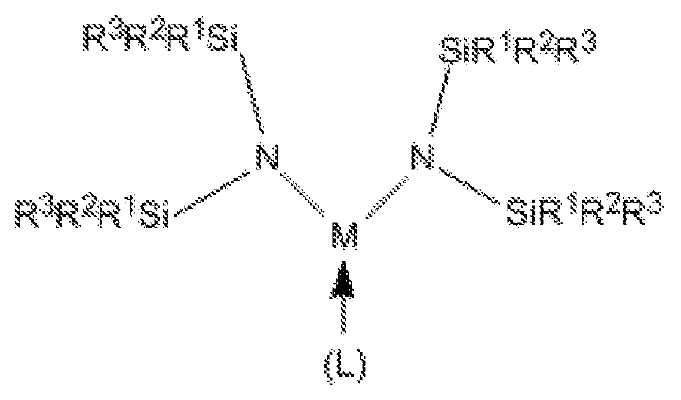
[화학식 I](I)
[화학식 II]≪ RTI ID = 0.0 &

(상기 식에서, M은 Mn이며; 각 R1, R2 및 R3은 독립적으로 수소(H) 또는 C1-C4 탄화수소로부터 선택되며; L은 피리딘, NMe3, NEt3, NMe2Et, NMeEt2, 1-Me-피롤리딘, 또는 PMe3으로부터 선택된 하나 또는 두 개의 중성 부가물이며; R1 및 R2, 또는 R2 및 R3은 결합되어 환형 규소-함유 헤테로사이클을 형성할 수 있음). 개시된 실릴아미드-함유 막 형성 조성물은 하기 양태들 중 하나 이상을 가질 수 있다:NMe 3 , NEt 3 , NMe 2 Et, NMeEt 2 (wherein each of R 1 , R 2 and R 3 is independently selected from hydrogen (H) or C 1 -
● 각 R1, R2 및 R3은 독립적으로 H, 메틸, 에틸, 이소프로필, n-프로필, n-부틸, 또는 t-부틸로부터 선택됨;Each R 1 , R 2 and R 3 is independently selected from H, methyl, ethyl, isopropyl, n-propyl, n-butyl or t-butyl;
● 화학식 I을 갖는 실릴아미드-함유 전구체;A silylamide-containing precursor having the formula I;
● 실릴아미드-함유 전구체는 Mn[N(SiMe3)2]2(py)임; ● silyl amide-containing precursor is Mn [N (SiMe 3) 2 ] 2 (py) Im;
● 실릴아미드-함유 전구체는 Mn[N(SiMe3)2]2(Me3N)임; ● silyl amide-containing precursor is Mn [N (SiMe 3) 2 ] 2 (Me 3 N) Im;
● 실릴아미드-함유 전구체는 Mn[N(SiMe3)2]2(Et3N)임; ● silyl amide-containing precursor is Mn [N (SiMe 3) 2 ] 2 (Et 3 N) Im;
● 실릴아미드-함유 전구체는 Mn[N(SiMe3)2]2(Me2EtN)임; ● silyl amide-containing precursor is Mn [N (SiMe 3) 2 ] 2 (Me 2 EtN) Im;
● 실릴아미드-함유 전구체는 Mn[N(SiMe3)2]2(MeEt2N)임; ● silyl amide-containing precursor is Mn [N (SiMe 3) 2 ] 2 (MeEt 2 N) Im;
● 실릴아미드-함유 전구체는 Mn[N(SiMe3)2]2(1-Me-피롤리딘)임; ● silyl amide-containing precursor is Mn [N (SiMe 3) 2 ] 2 (1-Me- pyrrolidine) Im;
● 실릴아미드-함유 전구체는 Mn[N(SiMe3)2]2(PMe3)임; ● silyl amide-containing precursor is Mn [N (SiMe 3) 2 ] 2 (PMe 3) Im;
● 실릴아미드-함유 전구체는 Mn[N(SiMe2Et)2]2(Me3N)임;The silylamide-containing precursor is Mn [N (SiMe 2 Et) 2 ] 2 (Me 3 N);
● 실릴아미드-함유 전구체는 Mn[N(SiMe2Et)2]2(Et3N)임; ● silyl amide-containing precursor is Mn [N (SiMe 2 Et) 2] 2 (Et 3 N) Im;
● 실릴아미드-함유 전구체는 Mn[N(SiMe2Et)2]2(Me2EtN)임;The silylamide-containing precursor is Mn [N (SiMe 2 Et) 2 ] 2 (Me 2 EtN);
● 실릴아미드-함유 전구체는 Mn[N(SiMe2Et)2]2(MeEt2N)임; The silylamide-containing precursor is Mn [N (SiMe 2 Et) 2 ] 2 (MeEt 2 N);
● 실릴아미드-함유 전구체는 Mn[N(SiMe2Et)2]2(1-Me-피롤리딘)임; The silylamide-containing precursor is Mn [N (SiMe 2 Et) 2 ] 2 (1-Me-pyrrolidine);
● 실릴아미드-함유 전구체는 Mn[N(SiMe2Et)2]2(PMe3)임,The silylamide-containing precursor is Mn [N (SiMe 2 Et) 2 ] 2 (PMe 3 )
● 화학식 II를 갖는 실릴아미드-함유 전구체;A silylamide-containing precursor having the formula II;
● 실릴아미드-함유 전구체는 {Mn[N(SiMe2Et)2]2}2임; ● silyl amide-containing precursor {Mn [N (SiMe 2 Et ) 2] 2} 2 being;
● 실릴아미드-함유 전구체는 {Mn[N(SiMe2H)2]2}2임; The silylamide-containing precursor is {Mn [N (SiMe 2 H) 2 ] 2 } 2 ;
● 실릴아미드-함유 전구체는 {Mn[N(SiMe3)(tBu)]2}2임; ● silyl amide-containing precursor {Mn [N (SiMe 3) (tBu)] 2} 2 being;
● 실릴아미드-함유 전구체는 {Mn[N(SiMe2nBu)2]2}2임; The silylamide-containing precursor is {Mn [N (SiMe 2 nBu) 2 ] 2 } 2 ;
● 실릴아미드-함유 전구체는 {Mn[N(SiMeEt2)2]2}2임;● silyl amide-containing precursor {Mn [N (SiMeEt 2) 2] 2} 2 being;
● 실릴아미드-함유 전구체는 Mn[N(SiMe2Et)2]2(py)임;The silylamide-containing precursor is Mn [N (SiMe 2 Et) 2 ] 2 (py);
● 대략 99% w/w 내지 대략 100% w/w의 실릴아미드-함유 전구체를 포함하는 망간-함유 막 형성 조성물;A manganese-containing film forming composition comprising about 99% w / w to about 100% w / w of a silylamide-containing precursor;
● 50℃에서 4주 후 대략 99% w/w 내지 대략 100% w/w의 실릴아미드-함유 전구체를 포함하는 망간-함유 막 형성 조성물;A manganese-containing film forming composition comprising about 99% w / w to about 100% w / w of a silylamide-containing precursor after 4 weeks at 50 ° C;
● 실온(대략 23℃)에서 12주 후 대략 99% w/w 내지 대략 100% w/w의 실릴아미드-함유 전구체를 포함하는 망간-함유 막 형성 조성물;A manganese-containing film forming composition comprising about 99% w / w to about 100% w / w of a silylamide-containing precursor after 12 weeks at room temperature (about 23 ° C);
● 1 Torr 증기압의 실릴아미드-함유 전구체를 생성하는 온도에서 2주의 안정성 시험 후 열중량 측정 분석 하에서 3% 미만의 잔류 질량을 생성시키는 망간-함유 막 형성 조성물;A manganese-containing film forming composition that produces a residual mass of less than 3% under thermogravimetric analysis after a two week stability test at a temperature producing a silylamide-containing precursor of 1 Torr vapor pressure;
● 1 Torr 증기압의 실릴아미드-함유 전구체를 생성하는 온도에서 3주의 안정성 시험 후 열중량 측정 분석 하에서 3% 미만의 잔류 질량을 생성시키는 망간-함유 막 형성 조성물;A manganese-containing film forming composition that produces a residual mass of less than 3% under thermogravimetric analysis after a three week stability test at a temperature producing a silylamide-containing precursor of 1 Torr vapor pressure;
● 1 Torr 증기압의 실릴아미드-함유 전구체를 생성하는 온도에서 2개월의 안정성 시험 후 열중량 측정 분석 하에서 3% 미만의 잔류 질량을 생성시키는 망간-함유 막 형성 조성물;A manganese-containing film forming composition that produces a residual mass of less than 3% under thermogravimetric analysis after two months of stability testing at a temperature producing a silylamide-containing precursor of 1 Torr vapor pressure;
● 대략 95% w/w 내지 대략 100% w/w의 실릴아미드-함유 전구체를 포함하는 망간-함유 막 형성 조성물;A manganese-containing film forming composition comprising about 95% w / w to about 100% w / w of a silylamide-containing precursor;
● 대략 5% w/w 내지 대략 50% w/w의 실릴아미드-함유 전구체를 포함하는 Mn-함유 막 형성 조성물;A Mn-containing film forming composition comprising about 5% w / w to about 50% w / w of a silylamide-containing precursor;
● 물을 포함하지 않는 Mn-함유 막 형성 조성물;• a water-free Mn-containing film forming composition;
● 대략 0% w/w 내지 대략 5% w/w 불순물을 포함하는 Mn-함유 막 형성 조성물;A Mn-containing film forming composition comprising about 0% w / w to about 5% w / w impurities;
● 대략 0.0% w/w 내지 대략 2.0% w/w 불순물을 포함하는 Mn-함유 막 형성 조성물;A Mn-containing film forming composition comprising from about 0.0% w / w to about 2.0% w / w impurity;
● 대략 0.0% w/w 내지 대략 1.0% w/w 불순물을 포함하는 Mn-함유 막 형성 조성물;A Mn-containing film forming composition comprising from about 0.0% w / w to about 1.0% w / w impurity;
● 할라이드, 알칼리 금속, 알킬-치환된 실란, 리튬, 소듐, 또는 포타슘 할라이드; THF; 에테르; 펜탄; 시클로헥산; 헵탄; 벤젠; 톨루엔을 포함하는 불순물;Halide, alkali metal, alkyl-substituted silane, lithium, sodium, or potassium halide; THF; ether; Pentane; Cyclohexane; Heptane; benzene; Impurities including toluene;
● 대략 0 ppbw 내지 대략 1 ppmw 금속 불순물을 포함하는 Mn-함유 막 형성 조성물;A Mn-containing film forming composition comprising from about 0 ppbw to about 1 ppmw metal impurities;
● 대략 0 ppbw 내지 대략 500 ppbw 금속 불순물을 포함하는 Mn-함유 막 형성 조성물;A Mn-containing film forming composition comprising from about 0 ppbw to about 500 ppbw metal impurities;
● 대략 0 ppbw 내지 대략 100 ppbw Al을 포함하는 Mn-함유 막 형성 조성물;A Mn-containing film forming composition comprising from about 0 ppbw to about 100 ppbw Al;
● 대략 0 ppbw 내지 대략 100 ppbw As를 포함하는 Mn-함유 막 형성 조성물;A Mn-containing film forming composition comprising from about 0 ppbw to about 100 ppbw As;
● 대략 0 ppbw 내지 대략 100 ppbw Ba를 포함하는 Mn-함유 막 형성 조성물;A Mn-containing film forming composition comprising about 0 ppbw to about 100 ppbw Ba;
● 대략 0 ppbw 내지 대략 100 ppbw Be를 포함하는 Mn-함유 막 형성 조성물;A Mn-containing film forming composition comprising from about 0 ppbw to about 100 ppbw Be;
● 대략 0 ppbw 내지 대략 100 ppbw Bi를 포함하는 Mn-함유 막 형성 조성물;A Mn-containing film forming composition comprising from about 0 ppbw to about 100 ppbw Bi;
● 대략 0 ppbw 내지 대략 100 ppbw Cd를 포함하는 Mn-함유 막 형성 조성물;A Mn-containing film forming composition comprising from about 0 ppbw to about 100 ppbw Cd;
● 대략 0 ppbw 내지 대략 100 ppbw Ca를 포함하는 Mn-함유 막 형성 조성물;A Mn-containing film forming composition comprising from about 0 ppbw to about 100 ppbw Ca;
● 대략 0 ppbw 내지 대략 100 ppbw Cr을 포함하는 Mn-함유 막 형성 조성물;A Mn-containing film forming composition comprising from about 0 ppbw to about 100 ppbw Cr;
● 대략 0 ppbw 내지 대략 100 ppbw Co를 포함하는 Mn-함유 막 형성 조성물;A Mn-containing film forming composition comprising from about 0 ppbw to about 100 ppbw Co;
● 대략 0 ppbw 내지 대략 100 ppbw Cu를 포함하는 Mn-함유 막 형성 조성물;A Mn-containing film forming composition comprising from about 0 ppbw to about 100 ppbw Cu;
● 대략 0 ppbw 내지 대략 100 ppbw Ga를 포함하는 Mn-함유 막 형성 조성물;A Mn-containing film forming composition comprising from about 0 ppbw to about 100 ppbw Ga;
● 대략 0 ppbw 내지 대략 100 ppbw Ge를 포함하는 Mn-함유 막 형성 조성물;A Mn-containing film forming composition comprising from about 0 ppbw to about 100 ppbw Ge;
● 대략 0 ppbw 내지 대략 100 ppbw Hf를 포함하는 Mn-함유 막 형성 조성물;A Mn-containing film forming composition comprising from about 0 ppbw to about 100 ppbw Hf;
● 대략 0 ppbw 내지 대략 100 ppbw Zr을 포함하는 Mn-함유 막 형성 조성물;A Mn-containing film forming composition comprising from about 0 ppbw to about 100 ppbw Zr;
● 대략 0 ppbw 내지 대략 100 ppbw In을 포함하는 Mn-함유 막 형성 조성물;A Mn-containing film forming composition comprising from about 0 ppbw to about 100 ppbw In;
● 대략 0 ppbw 내지 대략 100 ppbw Fe를 포함하는 Mn-함유 막 형성 조성물;A Mn-containing film forming composition comprising from about 0 ppbw to about 100 ppbw Fe;
● 대략 0 ppbw 내지 대략 100 ppbw Pb를 포함하는 Mn-함유 막 형성 조성물;A Mn-containing film forming composition comprising from about 0 ppbw to about 100 ppbw Pb;
● 대략 0 ppbw 내지 대략 100 ppbw Li를 포함하는 Mn-함유 막 형성 조성물;A Mn-containing film forming composition comprising about 0 ppbw to about 100 ppbw Li;
● 대략 0 ppbw 내지 대략 100 ppbw Mg를 포함하는 Mn-함유 막 형성 조성물;A Mn-containing film forming composition comprising from about 0 ppbw to about 100 ppbw Mg;
● 대략 0 ppbw 내지 대략 100 ppbw W를 포함하는 Mn-함유 막 형성 조성물;A Mn-containing film forming composition comprising from about 0 ppbw to about 100 ppbw W;
● 대략 0 ppbw 내지 대략 100 ppbw Ni를 포함하는 Mn-함유 막 형성 조성물;A Mn-containing film forming composition comprising from about 0 ppbw to about 100 ppbw Ni;
● 대략 0 ppbw 내지 대략 100 ppbw K를 포함하는 Mn-함유 막 형성 조성물;A Mn-containing film forming composition comprising from about 0 ppbw to about 100 ppbw K;
● 대략 0 ppbw 내지 대략 100 ppbw Na를 포함하는 Mn-함유 막 형성 조성물;A Mn-containing film forming composition comprising about 0 ppbw to about 100 ppbw Na;
● 대략 0 ppbw 내지 대략 100 ppbw Sr을 포함하는 Mn-함유 막 형성 조성물;A Mn-containing film forming composition comprising about 0 ppbw to about 100 ppbw Sr;
● 대략 0 ppbw 내지 대략 100 ppbw Th를 포함하는 Mn-함유 막 형성 조성물;A Mn-containing film forming composition comprising from about 0 ppbw to about 100 ppbw Th;
● 대략 0 ppbw 내지 대략 100 ppbw Sn을 포함하는 Mn-함유 막 형성 조성물;A Mn-containing film forming composition comprising from about 0 ppbw to about 100 ppbw Sn;
● 대략 0 ppbw 내지 대략 100 ppbw Ti를 포함하는 Mn-함유 막 형성 조성물;A Mn-containing film forming composition comprising from about 0 ppbw to about 100 ppbw Ti;
● 대략 0 ppbw 내지 대략 100 ppbw U를 포함하는 Mn-함유 막 형성 조성물;A Mn-containing film forming composition comprising from about 0 ppbw to about 100 ppbw U;
● 대략 0 ppbw 내지 대략 100 ppbw V를 포함하는 Mn-함유 막 형성 조성물; A Mn-containing film forming composition comprising from about 0 ppbw to about 100 ppbw V;
● 대략 0 ppbw 내지 대략 100 ppbw Zn을 포함하는 Mn-함유 막 형성 조성물;A Mn-containing film forming composition comprising about 0 ppbw to about 100 ppbw Zn;
● 대략 0 ppmw 내지 대략 100 ppmw Cl을 포함하는 Mn-함유 막 형성 조성물;A Mn-containing film forming composition comprising from about 0 ppmw to about 100 ppmw Cl;
● 대략 0 ppmw 내지 대략 100 ppmw Br을 포함하는 Mn-함유 막 형성 조성물.A Mn-containing film forming composition comprising from about 0 ppmw to about 100 ppmw Br.
또한, 유입구 도관 및 유출구 도관을 갖는 캐니스터를 포함하고 임의의 상술된 Mn-함유 막 형성 조성물을 함유하는 Mn-함유 막 형성 조성물 전달 장치가 개시된다. 개시된 장치는 하기 양태들 중 하나 이상을 포함할 수 있다:Also disclosed is a Mn-containing film forming composition delivery device comprising a canister having an inlet conduit and an outlet conduit and containing any of the Mn-containing film forming compositions described above. The disclosed apparatus can include one or more of the following aspects:
● 10 ppmw 미만의 금속 오염물질의 총 농도를 갖는 Mn-함유 막 형성 조성물;A Mn-containing film forming composition having a total concentration of metal contaminants of less than 10 ppmw;
● Mn-함유 막 형성 조성물의 표면 위에 위치된 유입구 도관 단부의 단부, 및 Mn-함유 막 형성 조성물의 표면 아래에 위치된 유출구 도관의 단부;The end of the inlet conduit end located above the surface of the Mn-containing film forming composition and the end of the outlet conduit located below the surface of the Mn-containing film forming composition;
● Mn-함유 막 형성 조성물의 표면 아래에 위치된 유입구 도관 단부의 단부 및 Mn-함유 막 형성 조성물의 표면 위에 위치된 유출구 도관의 단부;An end of the inlet conduit end positioned below the surface of the Mn-containing film forming composition and an outlet conduit end located above the surface of the Mn-containing film forming composition;
● 유입구 및 유출구 상에 다이아프램 밸브를 추가로 포함함;- further comprising a diaphragm valve on the inlet and outlet;
● 캐니스터의 내부 표면 상에 하나 이상의 배리어 층을 추가로 포함함;- further comprising at least one barrier layer on the inner surface of the canister;
● 캐니스터의 내부 표면 상에 하나 내지 네 개의 배리어 층을 추가로 포함함;- further comprising one to four barrier layers on the inner surface of the canister;
● 캐니스터의 내부 표면 상에 하나 또는 두 개의 배리어 층을 추가로 포함함;- further comprising one or two barrier layers on the inner surface of the canister;
● 산화규소 층, 질화규소 층, 산질화규소 층, 탄질화규소, 산탄질화규소 층, 또는 이들의 조합을 포함하는 각 배리어 층;Each barrier layer comprising a silicon oxide layer, a silicon nitride layer, a silicon oxynitride layer, a silicon carbonitride, a silicon oxynitride layer, or a combination thereof;
● 여기서, 각 배리어 층은 5 내지 1000 nm 두께임;Wherein each barrier layer is 5 to 1000 nm thick;
● 여기서, 각 배리어 층은 50 내지 500 nm 두께임;Wherein each barrier layer is 50 to 500 nm thick;
● {Mn[N(SiMe2Et)2]2}2를 포함하는 Mn-함유 막 형성 조성물. ● {Mn [N (SiMe 2 Et) 2] 2} 2 Mn- containing film-forming composition comprising a.
또한, 기판 상에 Mn-함유 층을 증착시키는 방법이 개시된다. 임의의 상술된 Mn-함유 막 형성 조성물의 증기는 그 안에 기판이 배치된 반응기에 도입된다. 실릴아미드-함유 전구체의 적어도 일부는 증기 증착 방법을 이용하여 Mn-함유 층을 형성하기 위해 기판 상에 증착된다. 개시된 방법은 하기 양태들 중 하나 이상을 가질 수 있다:Also disclosed is a method for depositing a Mn-containing layer on a substrate. The vapor of any of the above-mentioned Mn-containing film forming compositions is introduced into the reactor in which the substrate is placed. At least a portion of the silylamide-containing precursor is deposited on the substrate to form a Mn-containing layer using a vapor deposition process. The disclosed method can have one or more of the following aspects:
● 화학식 {Mn[N(SiMe2Et)2]2}2를 갖는 실릴아미드-함유 전구체를 포함하는 Mn-함유 막 형성 조성물;● the formula {Mn [N (SiMe 2 Et ) 2] 2} silyl amides having 2 - Mn- containing film-forming composition comprising a containing precursor;
● 반응기에 제2 전구체를 포함하는 증기를 도입함;Introducing a vapor comprising a second precursor into the reactor;
● 제2 전구체의 원소는 2족, 13족, 14족, 전이 금속, 란탄족 원소(lanthanide), 및 이들의 조합으로 이루어진 군으로부터 선택됨;The elements of the second precursor are selected from the group consisting of
● 제2 전구체의 원소는 Mg, Ca, Sr, Ba, Zr, Hf, Ti, Nb, Ta, Al, Si, Ge, Y, 또는 란탄족 원소로부터 선택됨;The element of the second precursor is selected from Mg, Ca, Sr, Ba, Zr, Hf, Ti, Nb, Ta, Al, Si, Ge, Y,
● 반응물을 반응기에 도입함;Introducing reactants into the reactor;
● 반응물은 O2, O3, H2O, H2O2, NO, NO2, 카르복실산, 이들의 라디칼, 및 이들의 조합으로 이루어진 군으로부터 선택됨;The reactants are selected from the group consisting of O 2 , O 3 , H 2 O, H 2 O 2 , NO, NO 2 , carboxylic acids, radicals thereof, and combinations thereof;
● 반응물은 플라즈마 처리된 산소임;The reactants are plasma treated oxygen;
● 반응물은 오존임;● Reactant is ozone;
● 반응물은 H2, NH3, (SiH3)3N, 히드리도실란(예를 들어, SiH4, Si2H6, Si3H8, Si4H10, Si5H10, Si6H12), 클로로실란 및 클로로폴리실란(예를 들어, SiHCl3, SiH2Cl2, SiH3Cl, Si2Cl6, Si2HCl5, Si3Cl8), 알키실란(예를 들어, Me2SiH2, Et2SiH2, MeSiH3, EtSiH3), 히드라진(예를 들어, N2H4, MeHNNH2, MeHNNHMe), 유기 아민(예를 들어, NMeH2, NEtH2, NMe2H, NEt2H, NMe3, NEt3, (SiMe3)2NH), 피라졸린, 피리딘, B-함유 분자(예를 들어, B2H6, 9-보라비시클로[3,3,1]논, 트리메틸보론, 트리에틸보론, 보라진), 알킬 금속(예를 들어, 트리메틸알루미늄, 트리에틸알루미늄, 디메틸아연, 디에틸아연), 이들의 라디칼 종, 및 이들의 혼합물로 이루어진 군으로부터 선택됨;The reactants may include H 2 , NH 3 , (SiH 3 ) 3 N, hydridosilane (eg, SiH 4 , Si 2 H 6 , Si 3 H 8 , Si 4 H 10 , Si 5 H 10 , Si 6 H 12 ), chlorosilanes and chloropolysilanes (e.g., SiHCl 3 , SiH 2 Cl 2 , SiH 3 Cl, Si 2 Cl 6 , Si 2 HCl 5 , Si 3 Cl 8 ), alkoxysilanes 2 SiH 2, Et 2 SiH 2 ,
● 반응물은 H2, NH3, SiH4, Si2H6, Si3H8, SiH2Me2, SiH2Et2, N(SiH3)3, 이들의 수소 라디칼, 및 이들의 혼합물로 이루어진 군으로부터 선택됨;The reactants are composed of H 2 , NH 3 , SiH 4 , Si 2 H 6 , Si 3 H 8 , SiH 2 Me 2 , SiH 2 Et 2 , N (SiH 3 ) 3 , hydrogen radicals thereof, Selected from the group;
● 반응물은 NH3, N2H4, N(SiH3)3, N(CH3)H2, N(C2H5)H2, N(CH3)2H, N(C2H5)2H, N(CH3)3, N(C2H5)3, (SiMe3)2NH, (CH3)HNNH2, (CH3)2NNH2, 이들의 질소-함유 라디칼 종, 및 이들의 혼합물로 이루어진 군으로부터 선택됨;● the reaction is NH 3, N 2 H 4, N (SiH 3) 3, N (CH 3)
● 반응물은 HCDS 또는 PCDS임; • the reactants are HCDS or PCDS;
● 반응물은 플라즈마 처리된 N2임;The reactants are plasma treated N 2 ;
● 증기 증착 방법은 CVD 공정임;The vapor deposition process is a CVD process;
● 증기 증착 방법은 ALD 공정임; The vapor deposition process is an ALD process;
● 증기 증착 방법은 PEALD 공정임; The vapor deposition process is a PEALD process;
● 증기 증착 방법은 공간적 ALD 공정임;The vapor deposition method is a spatial ALD process;
● Mn-함유 층은 망간 옥사이드 층임;The Mn-containing layer is a manganese oxide layer;
● Mn-함유 층은 망간 니트라이드 층임;The Mn-containing layer is a manganese nitride layer;
● Mn-함유 층은 Mn임; 및The Mn-containing layer is Mn; And
● Mn-함유 층은 MnSi임.The Mn-containing layer is MnSi.
또한, 기판 상에 망간 실리케이트 자가 형성 배리어 층을 증착시키는 방법이 개시된다. 임의의 상술된 Mn-함유 막 형성 조성물의 증기는 그 안에 기판이 배치된 반응기에 도입되며, 기판은 그 위에 규소-기반 절연 층에 형성된 비아(via)를 가지며, 규소-기반 절연 층은 비아의 측벽을 형성하며, 금속 라인은 비아의 하부를 형성한다. 실릴아미드-함유 전구체의 적어도 일부는 증기 증착 방법을 이용하여 망간 실리케이트 자가 형성 층을 형성하기 위해, 비아의 하부가 아닌, 측벽 상에 증착된다. 개시된 방법은 하기 양태들 중 하나 이상을 가질 수 있다:Also disclosed is a method of depositing a manganese silicate self-forming barrier layer on a substrate. The vapor of any of the Mn-containing film forming compositions described above is introduced into a reactor in which the substrate is disposed, the substrate having a via thereon formed in a silicon-based insulating layer, wherein the silicon- Forming a sidewall, the metal line forming the bottom of the via. At least a portion of the silylamide-containing precursor is deposited on the sidewalls, not the bottom of the vias, to form the manganese silicate self-assembled layer using a vapor deposition process. The disclosed method can have one or more of the following aspects:
● 화학식 {Mn[N(SiMe2Et)2]2}2를 갖는 실릴아미드-함유 전구체를 포함하는 Mn-함유 막 형성 조성물;● the formula {Mn [N (SiMe 2 Et ) 2] 2} silyl amides having 2 - Mn- containing film-forming composition comprising a containing precursor;
● 대략 3:1 내지 대략 20:1 범위의 종횡비를 갖는 비아;Vias having an aspect ratio ranging from about 3: 1 to about 20: 1;
● Si 및 O를 함유한 규소-기반 절연 층;A silicon-based insulating layer containing Si and O;
● 규소-기반 절연 층은 열적으로 산화된 규소임;The silicon-based insulating layer is thermally oxidized silicon;
● 규소-기반 절연 층은 SiO2임;● silicon-based insulating layer being SiO 2;
● 규소-기반 절연 층은 SiOC임;The silicon-based insulating layer is SiOC;
● 규소-기반 절연 층은 다공성 SiOC임;The silicon-based insulating layer is porous SiOC;
● 금속 라인은 구리임;● metal line is copper;
● 증기 증착 방법은 CVD 공정임;The vapor deposition process is a CVD process;
● 증기 증착 방법은 ALD 공정임; The vapor deposition process is an ALD process;
● 증기 증착 방법은 PEALD 공정임; The vapor deposition process is a PEALD process;
● 증기 증착 방법은 공간적 ALD 공정임; 및The vapor deposition method is a spatial ALD process; And
● 기판을 어닐링함.● Annealing the substrate.
표기법 및 명칭Notation and name
특정 약어, 기호, 및 용어는 하기 설명 및 청구범위 전반에 걸쳐 사용되고, 하기를 포함한다.Certain abbreviations, symbols, and terms are used throughout the following description and claims, including the following.
본원에서 사용되는 부정 관사("a" 또는 "an")는 하나 이상을 의미한다.As used herein, the indefinite article ("a" or "an") means one or more.
본원에서 사용되는 용어 "대략" 또는 "약"은 기술된 값의 ±10%를 의미한다.The term " about " or " about " as used herein means +/- 10% of the stated value.
본원에 기술된 임의의 범위 및 모든 범위는 이의 종결점을 포함한다(즉, x=1 내지 4는 x=1, x=4, 및 x=이들 사이의 임의의 수를 포함한다).Any range and all ranges described herein include the termination thereof (i.e., x = 1 to 4 include x = 1, x = 4, and x = any number between them).
본원에서 사용되는 용어 "알킬 기"는 배타적으로 탄소 원자 및 수소 원자를 함유한 포화된 작용기를 지칭한다. 또한, 용어 "알킬 기"는 선형, 분지형, 또는 환형 알킬 기를 지칭한다. 선형 알킬 기의 예는 비제한적으로, 메틸 기, 에틸 기, 프로필 기, 부틸 기, 등을 포함한다. 분지형 알킬 기의 예는 비제한적으로, t-부틸을 포함한다. 환형 알킬 기의 예는 비제한적으로, 시클로프로필 기, 시클로펜틸 기, 시클로헥실 기, 등을 포함한다.The term " alkyl group " as used herein refers to a saturated functional group containing exclusively carbon and hydrogen atoms. In addition, the term " alkyl group " refers to a linear, branched, or cyclic alkyl group. Examples of linear alkyl groups include, but are not limited to, methyl, ethyl, propyl, butyl, and the like. Examples of branched alkyl groups include, but are not limited to, t-butyl. Examples of cyclic alkyl groups include, but are not limited to, cyclopropyl, cyclopentyl, cyclohexyl, and the like.
본원에서 사용되는 용어 "탄화수소"는 배타적으로 수소 및 탄소 원자를 함유하는 작용기를 의미한다. 작용기는 포화되거나(단지 단일 결합을 함유함) 불포화(이중 결합 또는 삼중 결합을 함유함)될 수 있다.The term " hydrocarbon " as used herein means a functional group containing exclusively hydrogen and carbon atoms. The functional group may be saturated (containing only a single bond) or unsaturated (containing a double bond or triple bond).
본원에서 사용되는 용어 "헤테로사이클"은 이의 고리의 일원으로서 적어도 두 개의 상이한 원소들의 원자를 갖는 환형 화합물을 의미한다.The term " heterocycle " as used herein means a cyclic compound having at least two atoms of different elements as members of its ring.
본원에서 사용되는 약어 "Me"는 메틸 기를 지칭하며, 약어 "Et"는 에틸 기를 지칭하며, 약어 "Pr"은 임의의 프로필 기(즉, n-프로필 또는 이소프로필)를 지칭하며, 약어 "iPr"은 이소프로필 기를 지칭하며, 약어 "Bu"는 임의의 부틸 기(n-부틸, 이소-부틸, t-부틸, 2차-부틸)를 지칭하며, 약어 "tBu"는 3차-부틸 기를 지칭하며, 약어 "sBu"는 2차-부틸 기를 지칭하며, 약어 "iBu"는 이소-부틸 기를 지칭하며, 약어 "Ph"는 페닐 기를 지칭하며, 약어 "py"는 피리딘 기를 지칭하며, 약어 "THF"는 테트라히드로푸란을 지칭하며, 약어 "Cp"는 시클로펜타디에닐 기를 지칭한다.As used herein, the abbreviation "Me" refers to a methyl group, the abbreviation "Et" refers to an ethyl group, the abbreviation "Pr" refers to any propyl group (ie, n-propyl or isopropyl) Refers to an isopropyl group and the abbreviation "Bu" refers to any butyl group (n-butyl, iso-butyl, t-butyl, secondary-butyl) and the abbreviation "tBu" refers to tert- And the abbreviation " py " refers to a pyridine group, and the abbreviation " THF " refers to a tert-butyl group, Quot; refers to tetrahydrofuran, and the abbreviation " Cp " refers to a cyclopentadienyl group.
원소의 주기율표로부터의 원소의 표준 약어가 본원에서 사용된다. 원소가 이러한 약어에 의해 언급될 수 있는 것으로 이해되어야 한다(예를 들어, Mn은 망간을 지칭하며, Si는 규소를 지칭하며, C는 탄소를 지칭한다. 등등).Standard abbreviations of elements from the Periodic Table of Elements are used herein. It should be understood that an element may be referred to by such an acronym (e.g., Mn refers to manganese, Si refers to silicon, C refers to carbon, etc.).
증착된 막 또는 층, 예를 들어, 망간 옥사이드가 명세서 및 청구범위 전반에 걸쳐 이의 적절한 화학량론에 대한 언급 없이 나열된다는 것을 유의한다. 층은 순수한(M) 층, 실리사이드(MoSip) 층, 카바이드(MoCp) 층, 니트라이드(MkNl) 층, 옥사이드(MnOm) 층, 또는 이들의 혼합물을 포함할 수 있으며, 여기서, M은 Mn이며; k, l, m, n, o, 및 p는 포괄적으로 1 내지 6의 범위이다. 예를 들어, 망간 실리사이드는 MnkSil이며, 여기서, k 및 l 각각은 0.5 내지 5의 범위이다. 임의의 언급된 층은 또한 산화규소 층, SinOm을 포함할 수 있으며, 여기서, n은 0.5 내지 1.5의 범위이며, m은 1.5 내지 3.5의 범위이다. 산화규소 층은 산화규소 기반 유전 물질, 예를 들어, 탄소-도핑된 산화규소 기반 저-k 유전 물질, 예를 들어, Applied Materials, Inc.에 의한 Black Diamond II 또는 III 물질일 수 있다. 대안적으로, 임의의 언급된 규소-함유 층은 순수한 규소일 수 있다. 임의의 규소-함유 층은 또한 도펀트, 예를 들어, B, C, P, As 및/또는 Ge를 포함할 수 있다.It is noted that deposited films or layers, e.g., manganese oxide, are listed throughout the specification and claims without reference to their appropriate stoichiometry. Layer is pure (M) layer, a silicide (M o Si p) layer, a carbide (M o C p) layer, nitrides (M k N l) layer, oxide (M n O m) layer, or a mixture thereof , Where M is Mn; k, l, m, n, o, and p range from 1 to 6 inclusively. For example, the manganese silicide is Mn k Si 1 , where k and l each range from 0.5 to 5. Any of the mentioned layers may also comprise a silicon oxide layer, Si n O m , where n ranges from 0.5 to 1.5 and m ranges from 1.5 to 3.5. The silicon oxide layer may be a silicon oxide based dielectric material, for example, a carbon-doped silicon oxide based low-k dielectric material, such as Black Diamond II or III material by Applied Materials, Inc. Alternatively, any of the aforementioned silicon-containing layers may be pure silicon. Any silicon-containing layer may also include a dopant, for example, B, C, P, As, and / or Ge.
본 발명의 본질 및 목적의 추가 이해를 위하여, 첨부된 도면과 함께 하기 상세한 설명이 참조될 것이며, 여기서, 유사한 구성요소는 동일하거나 유사한 참조 번호로 제공된다.
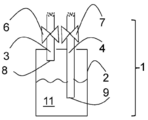
도 1은 Mn-함유 막 형성 조성물 전달 장치(1)의 일 구현예의 측단면도이다.
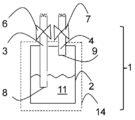
도 2는 Mn-함유 막 형성 조성물 전달 장치(1)의 제2 구현예의 측단면도이다.
도 3은 고체 Mn-함유 막 형성 조성물을 승화시키기 위한 고체 전구체 승화기(100)의 예시적 구현예의 측단면도이다.
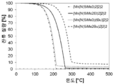
도 4는 {Mn[N(SiMe3)2]2}2, {Mn[N(SiMe2Et)2]2}2, {Mn[N(SiMe3)(tBu)2]2}2, 및 {Mn[N(SiMe2nBu)2]2}2의 온도 증가에 따른 중량 손실의 백분율을 나타낸, 1010 mbar 하에서의 비교 개방 컵 열중량 측정 분석(TGA) 그래프이다.
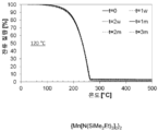
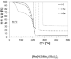
도 5는 안정성 시험 전 및 120℃에서 1주 및 2주, 및 1개월, 2개월 및 3개월 후에, {Mn[N(SiMe2Et)2]2}2의 온도 증가에 따른 중량 손실의 백분율을 나타낸 TGA 그래프이다.
도 6은 안정성 시험 전 및 90℃에서 1주 및 2주 후에, {Mn[N(SiMe3)(tBu)]2}2의 온도 증가에 따른 중량 손실의 백분율을 나타낸 TGA 그래프이다.
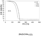
도 7은 안정성 시험 전 및 70℃에서 8주 및 3개월 후에, {Mn[N(SiMe3)2]2}2의 온도 증가에 따른 중량 손실의 백분율을 나타낸 TGA 그래프이다.
도 8은 안정성 시험 전 및 90℃에서 2주 및 4주 및 2개월 및 3개월 후에, {Mn[N(SiMe3)2]2}2의 온도 증가에 따른 중량 손실의 백분율을 나타낸 TGA 그래프이다.For a further understanding of the nature and objects of the present invention, reference will now be made to the following detailed description, taken in conjunction with the accompanying drawings, in which like elements are provided with like or similar reference numerals.
1 is a side cross-sectional view of one embodiment of the Mn-containing film forming
2 is a side cross-sectional view of a second embodiment of the Mn-containing film forming
3 is a side cross-sectional view of an exemplary embodiment of a
4 is {Mn [N (SiMe 3) 2] 2} 2, {Mn [N (
5 is a stability test before and at 120
6 is a TGA graph showing the percentage of weight loss with increasing temperature of {Mn [N (SiMe 3 ) (tBu)] 2 } 2 before and after 1 week and 2 weeks at 90 ° C.
7 is a stability test before and at 70
Figure 8 after 2 and 4 weeks and 2 months and 3 months stability tests prior to and 90 ℃, {Mn [N ( SiMe 3) 2] 2} 2 is a TGA graph showing the percent of weight loss due to temperature increase of the .
하기 화학식을 갖는 실릴아미드-함유 전구체를 포함하는 Mn-함유 막 형성 조성물이 개시된다:Disclosed is a Mn-containing film forming composition comprising a silylamide-containing precursor having the formula:
[화학식 I](I)

[화학식 II]≪ RTI ID = 0.0 &
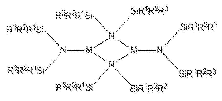
상기 식에서, M은 Mn이며; 각 R1, R2 및 R3은 독립적으로 수소(H) 또는 C1-C4 탄화수소로부터 선택되며; L은 피리딘, NMe3, NEt3, NMe2Et, NMeEt2, 1-Me-피롤리딘, 또는 PMe3으로부터 선택된 하나 또는 두 개의 중성 부가물이며; R1 및 R2, 또는 R2 및 R3은 결합되어 환형 규소-함유 헤테로사이클을 형성할 수 있다. 각 R1, R2 및 R3은 바람직하게, 독립적으로 H, 메틸, 에틸, 이소프로필, n-프로필, n-부틸, 또는 t-부틸이다.Wherein M is Mn; Each R 1 , R 2 and R 3 is independently selected from hydrogen (H) or C 1 -
화학식 I을 갖는 예시적인 실릴아미드 함유 전구체는 Mn[N(SiMe3)2]2(py); Mn[N(SiMe3)2]2(Me3N); Mn[N(SiMe3)2]2(Et3N); Mn[N(SiMe3)2]2(Me2EtN); Mn[N(SiMe3)2]2(MeEt2N); Mn[N(SiMe3)2]2(1-Me-피롤리딘); Mn[N(SiMe3)2]2(PMe3); Mn[N(SiMe2Et)2]2(py); Mn[N(SiMe2Et)2]2(Me3N); Mn[N(SiMe2Et)2]2(Et3N); Mn[N(SiMe2Et)2]2(Me2EtN); Mn[N(SiMe2Et)2]2(MeEt2N); Mn[N(SiMe2Et)2]2(1-Me-피롤리딘); Mn[N(SiMe2Et)2]2(PMe3), 및 이들의 조합을 포함한다.Exemplary silyl amides containing precursor having formula I is Mn [N (SiMe 3) 2 ] 2 (py); Mn [N (SiMe 3) 2 ] 2 (Me 3 N); Mn [N (SiMe 3) 2 ] 2 (Et 3 N); Mn [N (SiMe 3) 2 ] 2 (Me 2 EtN); Mn [N (SiMe 3) 2 ] 2 (MeEt 2 N); Mn [N (SiMe 3) 2 ] 2 (1-Me- pyrrolidine); Mn [N (SiMe 3) 2 ] 2 (PMe 3); Mn [N (SiMe 2 Et) 2] 2 (py); Mn [N (SiMe 2 Et) 2] 2 (Me 3 N); Mn [N (SiMe 2 Et) 2] 2 (Et 3 N); Mn [N (SiMe 2 Et) 2] 2 (Me 2 EtN); Mn [N (SiMe 2 Et) 2] 2 (MeEt 2 N); Mn [N (SiMe 2 Et) 2] 2 (1-Me- pyrrolidine); It includes Mn [N (SiMe 2 Et) 2] 2 (PMe 3), and combinations thereof.
화학식 II를 갖는 예시적인 실릴아미드 함유 전구체는 {Mn[N(SiMe3)2]2}2; {Mn[N(SiMe2Et)2]2}2; {Mn[N(SiMeEt2)2]2}2; {Mn[N(SiMe2H)2]2}2; {Mn[N(SiMe3)(tBu)]2}2; {Mn[N(SiMe2nBu)2]2}2; 및 이들의 조합을 포함한다. 바람직하게, 화학식 II를 갖는 예시적인 실릴아미드 함유 전구체는 {Mn[N(SiMe2Et)2]2}2; {Mn[N(SiMeEt2)2]2}2; {Mn[N(SiMe2H)2]2}2; {Mn[N(SiMe3)(tBu)]2}2; {Mn[N(SiMe2nBu)2]2}2; 및 이들의 조합이고, 더욱 바람직하게, {Mn[N(SiMe2Et)2]2}2이다.Exemplary silyl amides containing precursor having the formula II is {Mn [N (SiMe 3) 2] 2} 2; {Mn [N (SiMe 2 Et ) 2] 2} 2; {Mn [N (SiMeEt 2) 2] 2} 2; {Mn [N (SiMe 2 H) 2 ] 2 } 2 ; {Mn [N (SiMe 3) (tBu)] 2} 2; {Mn [N (SiMe 2 nBu) 2 ] 2 } 2 ; And combinations thereof. Preferably, the {Mn [N (SiMe 2 Et ) 2] 2} Exemplary silyl amides containing precursor having the formula II 2; {Mn [N (SiMeEt 2) 2] 2} 2; {Mn [N (SiMe 2 H) 2 ] 2 } 2 ; {Mn [N (SiMe 3) (tBu)] 2} 2; {Mn [N (SiMe 2 nBu) 2 ] 2 } 2 ; And a combination thereof, more preferably, {Mn [N (SiMe 2 Et) 2] 2} 2.
실릴아미드-함유 전구체는 테트라히드로푸란(THF), 에테르, 펜탄, 시클로헥산, 헥산, 헵탄, 또는 톨루엔과 같은 용매 중에서 MnX2(여기서, X는 Cl, Br, 또는 I임)를 M(N(SiR1R2R3)2)(여기서, M은 Li, Na, 또는 K임)과 반응시킴으로써 합성될 수 있다. 용매는 제거될 수 있으며, 화학식 I 또는 화학식 II의 생성물은 여과 및/또는 승화를 이용하여 염 부산물로부터 단리된다. 화학식 I의 L=THF 부가물은 THF-함유 전구체의 펜탄, 헵탄, 헥산 또는 시클로헥산과 같은 알칸 용액에 양성자화된 형태의 요망되는 리간드를 첨가하고, 생성물을 추출함으로써 치환될 수 있다. 추가 세부사항은 하기 실시예에서 제공된다.The silylamide-containing precursor is reacted with MnX 2 where X is Cl, Br, or I in a solvent such as tetrahydrofuran (THF), ether, pentane, cyclohexane, hexane, heptane, SiR 1 R 2 R 3 ) 2 ) (wherein M is Li, Na, or K). The solvent can be removed and the product of formula I or II is isolated from the salt by-product using filtration and / or sublimation. The L = THF adducts of formula (I) may be substituted by adding the desired ligand in the form of a protonated form of the THF-containing precursor to an alkane solution such as pentane, heptane, hexane or cyclohexane and extracting the product. Additional details are provided in the following examples.
공정 신뢰성을 보장하기 위하여, 개시된 Mn-함유 막 형성 조성물은 사용하기 전에 연속 또는 분별 배치 증류, 재결정화, 또는 승화에 의해 대략 95% w/w 내지 대략 100% w/w 범위, 바람직하게, 대략 98% w/w 내지 대략 100% w/w 범위의 순도까지 정제될 수 있다. Mn-함유 막 형성 조성물은 순도가 대략 99% w/w 내지 대략 100% w/w 범위일 때 본질적으로 실릴아미드-함유 전구체로 이루어진다. 당업자는, 순도가 H NMR, 또는 질량 분광법과 함께 가스 또는 액체 크로마토그래피에 의해 결정될 수 있음을 인식할 것이다. Mn-함유 막 형성 조성물은 임의의 하기 불순물을 함유할 수 있다: 할라이드, 알칼리 금속, 알킬 아민, 알킬아미노-치환된 실란, 피리딘, 1-메틸피롤리딘, 피롤리딘, THF, 에테르, 펜탄, 시클로헥산, 헵탄, 톨루엔, 할로겐화된 금속 화합물. 바람직하게, 이러한 불순물의 총량은 0.1% w/w 미만이다. 정제된 조성물은 재결정화, 승화, 증류에 의해 및/또는 4Å 분자체와 같은, 적합한 흡착제에 가스 또는 액체를 통과시킴으로써 생성될 수 있다.In order to ensure process reliability, the disclosed Mn-containing film forming compositions may be applied in a range of about 95% w / w to about 100% w / w, preferably about 100% w / w by continuous or fractional batch distillation, recrystallization, Can be purified to a purity ranging from 98% w / w to about 100% w / w. The Mn-containing film forming composition consists essentially of a silylamide-containing precursor when the purity ranges from about 99% w / w to about 100% w / w. One of skill in the art will recognize that purity can be determined by gas or liquid chromatography along with 1 H NMR, or mass spectrometry. The Mn-containing film forming composition may contain any of the following impurities: halide, alkali metal, alkylamine, alkylamino-substituted silane, pyridine, 1-methylpyrrolidine, pyrrolidine, THF, , Cyclohexane, heptane, toluene, halogenated metal compounds. Preferably, the total amount of such impurities is less than 0.1% w / w. The purified composition may be produced by passing a gas or liquid through a suitable adsorbent, such as by recrystallization, sublimation, distillation, and / or 4A molecular sieves.
정제된 Mn-함유 막 형성 조성물에서, THF, 에테르, 펜탄, 시클로헥산, 헵탄, 및/또는 톨루엔과 같은 각 용매의 농도는 대략 0% w/w 내지 대략 5% w/w, 바람직하게, 대략 0% w/w 내지 대략 0.1% w/w 범위일 수 있다. 용매는 Mn-함유 막 형성 조성물의 합성에서 사용될 수 있다. 조성물로부터 용매의 분리는 둘 모두가 유사한 비등점을 갖는 경우에 어려울 수 있다. 혼합물의 냉각은 액체 용매에서 고체 전구체를 생성시킬 수 있으며, 이는 여과에 의해 분리될 수 있다. 진공 증류가 또한 사용될 수 있으며, 단, 조성물은 대략 이의 분해점보다 높게 가열되지 않는다.In a purified Mn-containing film forming composition, the concentration of each solvent such as THF, ether, pentane, cyclohexane, heptane, and / or toluene is from about 0% w / w to about 5% w / w, 0% w / w to about 0.1% w / w. The solvent may be used in the synthesis of a Mn-containing film forming composition. Separation of the solvent from the composition may be difficult if both have similar boiling points. Cooling of the mixture can produce a solid precursor in a liquid solvent, which can be separated by filtration. Vacuum distillation can also be used, provided that the composition is not heated above its decomposition point.
개시된 Mn-함유 막 형성 조성물은 5% v/v 미만, 바람직하게, 1% v/v 미만, 더욱 바람직하게, 0.1% v/v 미만, 및 더욱더 바람직하게, 0.01% v/v 미만의 임의의 이의 유사체 또는 다른 반응 산물을 함유한다. 이러한 구현예는 보다 양호한 공정 반복성을 제공할 수 있다. 이러한 구현예는 Mn-함유 막 형성 조성물의 증류에 의해 생성될 수 있다.The disclosed Mn-containing film-forming compositions may contain any of the following: less than 5% v / v, preferably less than 1% v / v, more preferably less than 0.1% v / v, and even more preferably less than 0.01% v / Its analog or other reaction product. This embodiment can provide better process repeatability. This embodiment can be produced by distillation of the Mn-containing film forming composition.
대안적으로, 특히, 혼합물이 개선된 공정 파라미터를 제공하거나 타겟 화합물의 단리가 너무 어렵거나 고가일 때, 개시된 Mn-함유 막 형성 조성물은 대략 5% w/w 내지 대략 50% w/w의 하나의 화합물을 포함할 수 있으며, 조성물의 잔부는 제2 화합물을 포함한다. 예를 들어, 개시된 Mn-함유 막 형성 조성물은 40/60% w/w의 Mn[N(SiMe3)2]2(NMe2Et) 및 Mn[N(SiMe3)2]2(NMeEt2)일 수 있다. 혼합물은 증기 증착에 적합한 안정한 액체 조성물을 생성할 수 있다.Alternatively, particularly when the mixture provides improved process parameters or the isolation of the target compound is too difficult or expensive, the disclosed Mn-containing film forming composition may contain from about 5% w / w to about 50% w / w And the remainder of the composition comprises the second compound. For example, the disclosed Mn-containing film-forming compositions may comprise 40/60% w / w Mn [N (SiMe 3 ) 2 ] 2 (NMe 2 Et) and Mn [N (SiMe 3 ) 2 ] 2 (NMeEt 2 ) Lt; / RTI > The mixture can produce a stable liquid composition suitable for vapor deposition.
정제된 Mn-함유 막 형성 조성물에서 미량 금속 및 메탈로이드의 농도는 각각 독립적으로 대략 0 ppbw 내지 대략 100 ppbw, 및 더욱 바람직하게, 대략 0 ppbw 내지 대략 10 ppbw 범위일 수 있다. 이러한 금속 또는 메탈로이드 불순물은 알루미늄(Al), 비소(As), 바륨(Ba), 베릴륨(Be), 비스무트(Bi), 카드뮴(Cd), 칼슘(Ca), 크롬(Cr), 코발트(Co), 구리(Cu), 갈륨(Ga), 게르마늄(Ge), 하프늄(Hf), 지르코늄(Zr), 인듐(In), 철(Fe), 납(Pb), 리튬(Li), 마그네슘(Mg), 텅스텐(W), 니켈(Ni), 포타슘(K), 소듐(Na), 스트론튬(Sr), 토륨(Th), 주석(Sn), 티타늄(Ti), 우라늄(U), 바나듐(V) 및 아연(Zn)을 포함하지만, 이로 제한되지 않는다. 정제된 Mn-함유 막 형성 조성물에서 X(여기서, X는 Cl, Br임)의 농도는 대략 0 ppmw 내지 대략 100 ppmw, 및 더욱 바람직하게, 대략 0 ppmw 내지 대략 10 ppmw의 범위일 수 있다.In the refined Mn-containing film forming composition, the concentrations of trace metals and metalloids may each independently range from about 0 ppbw to about 100 ppbw, and more preferably from about 0 ppbw to about 10 ppbw. Such metal or metalloid impurities may be selected from the group consisting of Al, Ar, Ba, Ber, Bd, Cd, Ca, Cr, ), Copper (Cu), gallium (Ga), germanium (Ge), hafnium (Hf), zirconium (Zr), indium (In), iron (Fe), lead (Pb), lithium (Li) ), Tungsten (W), nickel (Ni), potassium (K), sodium (Na), strontium (Sr), thorium (Sn), titanium (Ti), uranium ), And zinc (Zn). In the purified Mn-containing film forming composition, the concentration of X (where X is Cl, Br) can range from about 0 ppmw to about 100 ppmw, and more preferably from about 0 ppmw to about 10 ppmw.
개시된 Mn-함유 막 형성 조성물의 물에 대한 노출이 실릴아민-함유 전구체의 분해를 초래할 수 있기 때문에, 이를 방지하는 것을 주의해야 한다.It should be noted that exposure to water of the disclosed Mn-containing film forming compositions can lead to decomposition of the silylamine-containing precursor, thereby preventing this.
또한, 증기 증착 방법을 위한 개시된 Mn-함유 막 형성 조성물을 사용하는 방법이 개시된다. 개시된 방법은 망간-함유 막의 증착을 위한 Mn-함유 막 형성 조성물의 용도를 제공한다. 개시된 방법은 반도체, 광전지, LCD-TFT, 평판 타입 디바이스, 내화물 또는 항공기의 제작에서 유용할 수 있다.Also disclosed is a method of using the disclosed Mn-containing film forming composition for a vapor deposition process. The disclosed process provides for the use of a Mn-containing film forming composition for the deposition of a manganese-containing film. The disclosed method may be useful in the fabrication of semiconductors, photovoltaic cells, LCD-TFTs, flat panel devices, refractories or aircraft.
기판 상에 망간-함유 층을 형성하는 개시된 방법은 반응기에 기판을 배치하고, 반응기에 개시된 Mn-함유 막 형성 조성물의 증기를 전달하고, 증기를 기판과 접촉시켜(그리고 통상적으로 증기를 기판으로 유도하여) 기판의 표면 상에 망간-함유 층을 형성하는 것을 포함한다.The disclosed method of forming a manganese-containing layer on a substrate involves placing the substrate in a reactor, delivering the vapor of the Mn-containing film-forming composition disclosed in the reactor, contacting the vapor with the substrate (and typically introducing the vapor into the substrate Thereby forming a manganese-containing layer on the surface of the substrate.
방법은 증기 증착 공정을 이용하여, 및 더욱 상세하게, MnMOx 막(여기서, x는 4이며, M은 Ta, Hf, Nb, Mg, Al, Sr, Y, Ba, Ca, As, Sb, Bi, Sn, Pb, Co, 란탄족 원소(예를 들어, Er), 또는 이들의 조합임)의 증착을 위해 기판 상에 이중금속-함유 층을 형성시키는 것을 포함할 수 있다. 개시된 방법은 반도체, 광전지, LCD-TFT, 또는 평판 타입 디바이스의 제작에서 유용할 수 있다. 산소 공급원, 예를 들어, O3, O2, H2O, NO, H2O2, 아세트산, 포르말린, 파라-포름알데히드, 이들의 산소 라디칼, 및 이들의 조합, 바람직하게는 O3 또는 플라즈마 처리된 O2가 또한 반응기에 도입될 수 있다.The method comprises the steps of using a vapor deposition process and more particularly a MnMO x film wherein x is 4 and M is Ta, Hf, Nb, Mg, Al, Sr, Y, Ba, Ca, As, Sb, Bi , A Sn, Pb, Co, a lanthanide element (e.g., Er), or a combination thereof) to form a double metal-containing layer on the substrate. The disclosed method may be useful in the fabrication of semiconductors, photovoltaic cells, LCD-TFTs, or flat panel type devices. Oxygen sources such as O 3 , O 2 , H 2 O, NO, H 2 O 2 , acetic acid, formalin, para-formaldehyde, their oxygen radicals and combinations thereof, preferably O 3 or plasma The treated O 2 can also be introduced into the reactor.
개시된 Mn-함유 막 형성 조성물은 당업자에게 공지된 임의의 증착 방법을 이용하여 망간-함유 막을 증착시키기 위해 사용될 수 있다. 적합한 증착 방법의 예는 화학적 증기 증착(CVD) 또는 원자층 증착(ALD)을 포함한다. 예시적인 CVD 방법은 열적 CVD, 펄스식 CVD(PCVD), 저압 CVD(LPCVD), 부기압 CVD(SACVD) 또는 대기압 CVD(APCVD), 고온-와이어 CVD(HWCVD, 또한 cat-CVD로서 알려짐, 여기서, 고온 와이어는 증착 공정을 위한 에너지원으로서 역할을 함), 라디칼 도입된 CVD, 유동성 PECVD를 포함하지만 이로 제한되지 않는 플라즈마 강화 CVD(PECVD) 및 이들의 조합을 포함한다. 예시적인 ALD 방법은 열적 ALD, 플라즈마 강화 ALD(PEALD), 공간적 단리 ALD, 고온-와이어 ALD(HWALD), 라디칼 도입된 ALD, 및 이들의 조합을 포함한다. 초임계 유체 증착이 또한 사용될 수 있다. 증착 방법은 적합한 단차 피복 및 막 두께 조절을 제공하기 위해 바람직하게 ALD, PE-ALD 또는 공간적 ALD이다.The disclosed Mn-containing film forming compositions can be used to deposit a manganese-containing film using any deposition method known to those skilled in the art. Examples of suitable deposition methods include chemical vapor deposition (CVD) or atomic layer deposition (ALD). Exemplary CVD methods are known as thermal CVD, pulsed CVD (PCVD), low pressure CVD (LPCVD), negative pressure CVD (SACVD) or atmospheric pressure CVD (APCVD), HWCVD, also known as cat- High temperature wire serves as an energy source for the deposition process), plasma enhanced CVD (PECVD) including, but not limited to, radical introduced CVD, flowable PECVD, and combinations thereof. Exemplary ALD methods include thermal ALD, plasma enhanced ALD (PEALD), spatially isolated ALD, high temperature-wire ALD (HWALD), radical introduced ALD, and combinations thereof. Supercritical fluid deposition may also be used. The deposition method is preferably ALD, PE-ALD or spatial ALD to provide suitable step coverage and film thickness control.
Mn-함유 막 형성 조성물의 증기가 발생되고, 이후에, 기판을 포함한 반응 챔버에 도입된다. 반응 챔버에서의 온도 및 압력, 및 기판의 온도는 기판 상에 실릴아민-함유 전구체의 적어도 일부의 증기 증착에 적합한 조건에서 유지된다. 다시 말해서, 반응 챔버에 증기화된 조성물의 도입 후에, 반응 챔버 내의 조건은 전구체의 적어도 일부가 Mn-함유 층을 형성하기 위해 기판 상에 증착되도록 조정된다. 당업자는 "전구체의 적어도 일부가 증착된다"가 전구체의 일부 또는 모두가 기판과 반응하거나 기판에 접착함을 의미한다는 것을 인식할 것이다. 본원에서, Mn-함유 층의 형성에 도움을 주기 위해 반응물이 사용될 수도 있다.A vapor of the Mn-containing film forming composition is generated and then introduced into the reaction chamber containing the substrate. The temperature and pressure in the reaction chamber and the temperature of the substrate are maintained under conditions suitable for vapor deposition of at least a portion of the silylamine-containing precursor on the substrate. In other words, after introduction of the vaporized composition into the reaction chamber, the conditions in the reaction chamber are adjusted such that at least a portion of the precursor is deposited on the substrate to form a Mn-containing layer. Those skilled in the art will recognize that " at least a portion of the precursor is deposited " means that some or all of the precursor reacts with or adheres to the substrate. In the present application, a reactant may be used to assist in the formation of the Mn-containing layer.
반응 챔버는 디바이스의 임의의 인클로져(enclosure) 또는 챔버일 수 있으며, 여기서, 증착 방법은 비제한적으로, 예를 들어, 평행판 타입 반응기, 냉각벽 타입 반응기, 고온벽 타입 반응기, 단일 웨이퍼 반응기, 다중 웨이퍼 반응기, 또는 다른 이러한 타입의 증착 시스템에서 일어난다. 모든 이러한 예시적 반응 챔버는 ALD 또는 CVD 반응 챔버로서 역할을 할 수 있다. 반응 챔버는 모든 ALD 및 부기압 CVD를 위해 약 0.5 mTorr 내지 약 20 Torr 범위의 압력에서 유지될 수 있다. 부기압 CVD 및 대기압 CVD 압력은 최대 760 Torr(대기압)의 범위일 수 있다. 또한, 반응 챔버 내의 온도는 약 20℃ 내지 약 600℃의 범위일 수 있다. 당업자는 요망되는 결과를 달성하기 위해 단순한 실험을 통해 온도가 최적화될 수 있다는 것을 인식할 것이다.The reaction chamber may be any enclosure or chamber of the device, wherein the deposition method may include, but is not limited to, a parallel plate type reactor, a cooling wall type reactor, a high temperature wall type reactor, a single wafer reactor, Wafer reactor, or other such type of deposition system. All such exemplary reaction chambers may serve as ALD or CVD reaction chambers. The reaction chamber may be maintained at a pressure ranging from about 0.5 mTorr to about 20 Torr for all ALD and subatmospheric CVD. The negative pressure CVD and atmospheric pressure CVD pressures may be in the range of up to 760 Torr (atmospheric pressure). In addition, the temperature in the reaction chamber may range from about 20 캜 to about 600 캜. Those skilled in the art will recognize that the temperature may be optimized through simple experimentation to achieve the desired result.
반응기의 온도는 기판 홀더의 온도를 조절하거나 반응기 벽의 온도를 조절함으로써 조절될 수 있다. 기판을 가열하기 위해 사용되는 디바이스는 당해 분야에 알려져 있다. 반응기 벽은 충분한 성장률로 그리고 요망되는 물리적 상태 및 조성을 갖는 요망되는 막을 얻기 위해 충분한 온도까지 가열된다. 반응기 벽이 가열될 수 있는 비제한적인 예시적 온도 범위는 대략 20℃ 내지 대략 600℃를 포함한다. 플라즈마 증착 공정이 사용될 때, 증착 온도는 대략 20℃ 내지 대략 550℃의 범위일 수 있다. 대안적으로, 열적 공정이 수행될 때, 증착 온도는 대략 300℃ 내지 대략 600℃의 범위일 수 있다.The temperature of the reactor can be adjusted by adjusting the temperature of the substrate holder or by controlling the temperature of the reactor wall. Devices used to heat the substrate are known in the art. The reactor walls are heated to a temperature sufficient to achieve the desired film with sufficient growth rate and desired physical state and composition. A non-limiting exemplary temperature range in which the reactor wall can be heated includes from about 20 占 폚 to about 600 占 폚. When a plasma deposition process is used, the deposition temperature may range from about 20 [deg.] C to about 550 [deg.] C. Alternatively, when a thermal process is performed, the deposition temperature may range from about 300 캜 to about 600 캜.
대안적으로, 기판은 충분한 성장률로 그리고 요망되는 물리적 상태 및 조성을 갖는 요망되는 망간-함유 막을 얻기 위해 충분한 온도까지 가열될 수 있다. 기판이 가열될 수 있는 비제한적인 예시적인 온도 범위는 150℃ 내지 600℃를 포함한다. 바람직하게, 기판의 온도는 500℃ 이하로 유지된다.Alternatively, the substrate can be heated to a temperature sufficient to obtain a desired manganese-containing film with a sufficient growth rate and desired physical state and composition. A non-limiting exemplary temperature range in which the substrate can be heated includes 150 deg. C to 600 deg. Preferably, the temperature of the substrate is maintained at 500 DEG C or lower.
반응기는 막이 증착될 하나 이상의 기판을 포함한다. 기판은 일반적으로 그 위에서 공정이 수행되는 물질로서 정의된다. 기판은 반도체, 광전지, 평판, 또는 LCD-TFT 디바이스 제작에서 사용되는 임의의 적합한 기판일 수 있다. 적합한 기판의 예는 웨이퍼, 예를 들어, 규소, 실리카, 유리, 또는 GaAs 웨이퍼를 포함한다. 웨이퍼는 이전 제작 단계로부터 그 위에 증착된 상이한 물질의 하나 이상의 층을 가질 수 있다. 예를 들어, 웨이퍼는 규소 층(결정질, 비정질, 다공성, 등), 산화규소 층, 질화규소 층, 산질화규소 층, 탄소 도핑된 산화규소(SiCOH) 층, 또는 이들의 조합을 포함할 수 있다. 추가적으로, 웨이퍼는 구리 층 또는 귀금속 층(예를 들어, 백금, 팔라듐, 로듐, 또는 금)을 포함할 수 있다. 층은 MIM, DRAM, 또는 FeRam 기술에서 유전체 물질(예를 들어, ZrO2 기반 물질, HfO2 기반 물질, TiO2 기반 물질, 희토류 옥사이드 기반 물질, 3원 옥사이드 기반 물질, 예를 들어, 스트론튬 루테늄 옥사이드[SRO], 등)으로서 또는 구리와 저-k 층 사이의 산소 배리어로서 사용되는 니트라이드-기반 막(예를 들어, TaN)으로부터 사용되는 옥사이드를 포함할 수 있다. 웨이퍼는 배리어 층, 예를 들어, 망간, 망간 옥사이드, 등을 포함할 수 있다. 플라스틱 층, 예를 들어, 폴리(3,4-에틸렌디옥시티오펜)폴리(스티렌설포네이트)[PEDOT:PSS]가 또한 사용될 수 있다. 층은 평평하거나 패터닝 될 수 있다. 예를 들어, 층은 수소화된 탄소, 예를 들어, CHx(여기서, x는 0보다 크다)로 제조된 패터닝 된 포토레지스트 막일 수 있다.The reactor includes at least one substrate on which the film is to be deposited. A substrate is generally defined as a material on which processes are performed. The substrate may be any suitable substrate used in semiconductor, photovoltaic, flat panel, or LCD-TFT device fabrication. Examples of suitable substrates include wafers, for example, silicon, silica, glass, or GaAs wafers. The wafer may have one or more layers of different materials deposited thereon from a previous fabrication step. For example, the wafer may comprise a silicon layer (crystalline, amorphous, porous, etc.), a silicon oxide layer, a silicon nitride layer, a silicon oxynitride layer, a carbon doped silicon oxide (SiCOH) layer, or a combination thereof. Additionally, the wafer may comprise a copper layer or a noble metal layer (e.g., platinum, palladium, rhodium, or gold). Layer may be a dielectric material (e.g., a ZrO 2 -based material, a HfO 2 -based material, a TiO 2 -based material, a rare earth oxide-based material, a ternary oxide based material such as a strontium ruthenium oxide (E.g., [SRO], etc.) or a nitride-based film (e.g., TaN) used as an oxygen barrier between copper and a low-k layer. The wafer may comprise a barrier layer, for example, manganese, manganese oxide, and the like. Plastic layers such as poly (3,4-ethylenedioxythiophene) poly (styrenesulfonate) [PEDOT: PSS] may also be used. The layer may be flat or patterned. For example, the layer may be a patterned photoresist film made of hydrogenated carbon, e.g., CH x (where x is greater than zero).
개시된 공정은 웨이퍼 상에 직접적으로 또는 웨이퍼의 상부 상의 하나 또는 하나 초과(패터닝 된 층이 기판을 형성할 때)의 층 상에 직접적으로 망간-함유 층을 증착할 수 있다. 기판은 높은 종횡비를 갖는 비아 또는 트렌치(trench)를 포함하도록 패터닝 될 수 있다. 예를 들어, 컨포멀 Mn-함유 막, 예를 들어, 망간 옥사이드는 대략 20:1 내지 대략 100:1 범위의 종횡비를 갖는 박막 고체 상태 배터리의 홀(hole) 또는 트렌치 상에 임의의 ALD 기술을 이용하여 증착될 수 있다. 또한, 당업자는 본원에서 사용되는 용어 "막" 또는 "층"이 표면 상에 놓여지거나 표면 위에 살포된 소정 두께의 일부 물질을 지칭하며 표면이 트렌치 또는 라인일 수 있음을 인식할 것이다. 명세서 및 청구범위 전반에 걸쳐, 웨이퍼 및 그 위의 임의의 관련된 층은 기판으로서 지칭된다. 그렇지만, 여러 경우에, 사용되는 바람직한 기판은 탄소-도핑된 옥사이드, TaN, Ta, TiN, Cu, Ru, 및 Si 타입 기판, 예를 들어, 폴리규소 또는 결정질 규소 기판으로부터 선택될 수 있다.The disclosed process can deposit a manganese-containing layer directly on a wafer or directly on one or more than one (when the patterned layer forms a substrate) on the top of the wafer. The substrate may be patterned to include vias or trenches having a high aspect ratio. For example, a conformal Mn-containing film, for example, manganese oxide, may be deposited on a hole or trench of a thin film solid state battery having an aspect ratio ranging from about 20: 1 to about 100: 1, Can be deposited. It will also be appreciated by those skilled in the art that the term " film " or " layer " as used herein refers to some material of a certain thickness that is placed on or spread over a surface and that the surface can be a trench or line. Throughout the specification and claims, the wafer and any associated layers thereon are referred to as substrates. However, in many cases, the preferred substrate used can be selected from carbon-doped oxide, TaN, Ta, TiN, Cu, Ru, and Si type substrates, e.g., polysilicon or crystalline silicon substrates.
개시된 Mn-함유 막 형성 조성물은 용매, 예를 들어, 톨루엔, 에틸벤젠, 자일렌, 메시틸렌, 데칸, 도데칸, 옥탄, 헥산, 펜탄, 3차 아민, 아세톤, 테트라히드로푸란, 에탄올, 에틸메틸케톤, 1,4-디옥산, 등을 추가로 포함할 수 있다. 개시된 조성물은 용매 중에 다양한 농도로 존재할 수 있다. 예를 들어, 얻어진 농도는 대략 0.05 M 내지 대략 2 M 범위일 수 있다.The disclosed Mn-containing film-forming compositions can be prepared by reacting the Mn-containing film forming composition with a solvent such as toluene, ethylbenzene, xylene, mesitylene, decane, dodecane, octane, hexane, pentane, tertiary amine, acetone, tetrahydrofuran, Ketones, 1,4-dioxane, and the like. The disclosed compositions may be present in the solvent at various concentrations. For example, the concentration obtained may range from about 0.05 M to about 2 M.
Mn-함유 막 형성 조성물은 Mn-함유 막 형성 조성물 전달 장치의 세 가지의 예시적인 구현예를 도시한 도 1 내지 도 3의 Mn-함유 막 형성 조성물 전달 장치에 의해 반응기로 전달될 수 있다.The Mn-containing film forming composition can be delivered to the reactor by the Mn-containing film forming composition delivery device of FIGS. 1 to 3 showing three exemplary embodiments of the Mn-containing film forming composition delivery device.
도 1은 Mn-함유 막 형성 조성물 반응물 전달 장치(1)의 일 구현예의 측면도이다. 도 1에서, 개시된 Mn-함유 막 형성 조성물(11)은 두 개의 도관, 즉, 유입구 도관(3) 및 유출구 도관(4)을 갖는 용기(2) 내에 함유된다. 반응물 분야의 당업자는 용기(2), 유입구 도관(3) 및 유출구 도관(4)이 상승된 온도 및 압력에서도 가스상 형태의 Mn-함유 막 형성 조성물(11)이 빠져나가는 것을 방지하도록 제작된다는 것을 인식할 것이다.1 is a side view of an embodiment of the Mn-containing film forming composition
전달 장치(1)의 유출구 도관(4)은 반응기(미도시됨)에 또는 전달 장치와 반응기 사이의 다른 구성요소, 예를 들어, 가스 캐비넷에 밸브(7)를 통해 유동적으로 연결된다. 바람직하게, 용기(2), 유입구 도관(3), 밸브(6), 유출구 도관(4), 및 밸브(7)는 316L EP 또는 304 스테인레스강으로 제조된다. 그러나, 당업자는 다른 비-반응성 물질이 또한, 본원의 교시에서 사용될 수 있다는 것을 인식할 것이다.The
도 1에서, 유입구 도관(3)의 단부(8)는 Mn-함유 막 형성 조성물(11)의 표면 위에 위치되며, 유출구 도관(4)의 단부(9)는 Mn-함유 막 형성 조성물(11)의 표면 아래에 위치된다. 이러한 구현예에서, Mn-함유 막 형성 조성물(11)은 바람직하게, 액체 형태이다. 질소, 아르곤, 헬륨, 및 이들의 혼합물을 포함하지만 이로 제한되지 않는 불활성 가스가 유입구 도관(3)에 도입될 수 있다. 불활성 가스는, 액체 Mn-함유 막 형성 조성물(11)이 유출구 도관(4)을 통해 그리고 반응기(미도시됨)로 강제로 이동되도록 전달 장치(2)에 압력을 가한다. 반응기는, 위에 막이 형성될 기판에 증기를 전달하기 위해, 헬륨, 아르곤, 질소 또는 이들의 혼합물과 같은 운반 가스를 사용하거나 사용하지 않으면서, 액체 Mn-함유 막 형성 조성물(11)을 증기로 변형시키는 증기화기를 포함할 수 있다. 대안적으로, 액체 Mn-함유 막 형성 조성물(10)은 제트 또는 에어로졸로서 웨이퍼 표면에 직접적으로 전달될 수 있다.1, the
도 2는 Mn-함유 막 형성 조성물 전달 장치(1)의 제2 구현예의 측면도이다. 도 2에서, 유입구 도관(3)의 단부(8)는 Mn-함유 막 형성 조성물(11)의 표면 아래에 위치되며, 유출구 도관(4)의 단부(9)는 Mn-함유 막 형성 조성물(11)의 표면 위에 위치된다. 도 2는 또한, 선택적 가열 부재(14)를 포함하며, 이는 Mn-함유 막 형성 조성물(11)의 온도를 증가시킬 수 있다. 일 구현예에서, Mn-함유 막 형성 조성물(11)은 고체 또는 액체 형태일 수 있다. 질소, 아르곤, 헬륨, 및 이들의 혼합물을 포함하지만, 이로 제한되지 않는 불활성 가스가, 유입구 도관(3)에 도입된다. 불활성 가스는 Mn-함유 막 형성 조성물(11)에 거품을 형성하고, 불활성 가스와 증기화된 Mn-함유 막 형성 조성물(11)의 혼합물을 유출구 도관(4)에 그리고 반응기 상으로 운반한다. 운반 가스로의 버블링은 또한, Mn-함유 막 형성 조성물에 존재하는 임의의 용해된 산소를 제거할 수 있다.2 is a side view of a second embodiment of the Mn-containing film forming
도 1 및 도 2는 밸브(6) 및 밸브(7)를 포함한다. 당업자는 밸브(6) 및 밸브(7)가 각각 도관(3) 및 도관(4)를 통해 흐르도록 개방된 위치 또는 닫혀진 위치에 배치될 수 있다는 것은 인식할 것이다. 도 1 및 도 2에서의 전달 장치(1), 또는 존재하는 임의의 고체 또는 액체의 표면 위에서 종결하는 단일 도관을 갖는 보다 단순한 전달 장치는, Mn-함유 막 형성 조성물(11)이 증기 형태인 경우에 또는 충분한 증기압이 고체/액체 상 위에 존재하는 경우에, 사용될 수 있다. 이러한 경우에, Mn-함유 막 형성 조성물(11)은 도 1에서 밸브(6) 또는 도 2에서 밸브(7)를 단순하게 개방시킴으로써 도관(3) 또는 도관(4)을 통해 증기 형태로 전달된다. 전달 장치(1)는 예를 들어, 선택적 가열 부재(14)의 사용에 의해 Mn-함유 막 형성 조성물(11)을 증기 형태로 전달하도록 충분한 증기압을 제공하기 위해 적합한 온도에서 유지될 수 있다.Figures 1 and 2 include a
도 1 및 도 2가 Mn-함유 막 형성 조성물 전달 장치(1)의 두 개의 구현예를 도시하지만, 당업자는 유입구 도관(3) 및 유출구 도관(4) 둘 모두가 또한 본원의 개시내용으로부터 벗어나지 않으면서, Mn-함유 막 형성 조성물(11)의 표면 위 또는 아래에 위치될 수 있다는 것을 인식할 것이다. 또한, 유입구 도관(3)은 충전 포트일 수 있다.Although Figures 1 and 2 illustrate two embodiments of the Mn-containing film forming
Mn-함유 막 형성 조성물의 고체 형태의 증기는 승화기를 이용하여 반응기로 전달될 수 있다. 도 3은 예시적인 승화기(100)의 일 구현예를 도시한 것이다. 승화기(100)는 용기(33)를 포함한다. 용기(33)는 실린더형 용기일 수 있거나, 대안적으로, 비제한적으로, 임의의 형상일 수 있다. 용기(33)는 비제한적으로, 스테인레스강, 니켈 및 이의 합금, 석영, 유리, 및 다른 화학적으로 양립 가능한 물질과 같은 물질로 구성된다. 특정 경우에, 용기(33)는 비제한적으로, 다른 금속 또는 금속 합금으로 구성된다. 특정 경우에, 용기(33)는 약 8 센티미터 내지 약 55 센티미터의 내부 직경, 및 대안적으로, 약 8 센티미터 내지 약 30 센티미터의 내부 직경을 갖는다. 당업자에 의해 이해되는 바와 같이, 대안적인 구성은 상이한 치수를 가질 수 있다.The vapor of the solid form of the Mn-containing film forming composition can be delivered to the reactor using a sublimation. FIG. 3 illustrates one embodiment of an
용기(33)는 밀봉 가능한 상부(sealable top)(15), 밀봉 부재(18), 및 가스켓(20)을 포함한다. 밀봉 가능한 상부(15)는 외부 환경으로부터 용기(33)를 밀봉하도록 구성된다. 밀봉 가능한 상부(15)는 용기(33)에 대한 접근을 허용하도록 구성된다. 추가적으로, 밀봉 가능한 상부(15)는 용기(33)로 도관이 통과하도록 구성된다. 대안적으로, 밀봉 가능한 상부(15)는 용기(33)로 유체 흐름을 가능하게 하도록 구성된다. 밀봉 가능한 상부(15)는 용기(33)와 유체 접촉을 유지하기 위해 딥 튜브(dip tube)(92)를 포함하는 도관을 수용하고 이를 통과시키도록 구성된다. 제어 밸브(90) 및 피팅(fitting)(95)을 갖는 딥 튜브(92)는 운반 가스를 용기(33)로 흐르게 하도록 구성된다. 특정 경우에, 딥 튜브(92)는 용기(33)의 중심축 아래로 연장된다. 또한, 밀봉 가능한 상부(15)는 유출구 튜브(12)를 포함하는 도관을 수용하고 이를 통과시키도록 구성된다. 운반 가스 및 Mn-함유 막 형성 조성물의 증기는 유출구 튜브(12)를 통해 용기(33)로부터 제거된다. 유출구 튜브(12)는 제어 밸브(10) 및 피팅(5)을 포함한다. 특정 경우에, 유출구 튜브(12)는 운반 가스를 승화기(100)로부터 반응기로 전달하기 위해, 가스 전달 매니폴드에 유동적으로 결합된다.The
용기(33) 및 밀봉 가능한 상부(15)는 적어도 두 개의 밀봉 부재(18)에 의해, 대안적으로, 적어도 약 네 개의 밀봉 부재에 의해 밀봉된다. 특정 경우에, 밀봉 가능한 상부(15)는 적어도 약 8개의 밀봉 부재(18)에 의해 용기(33)에 밀봉된다. 당업자에 의해 이해되는 바와 같이, 밀봉 부재(18)는 밀봉 가능한 상부(15)을 용기(33)에 분리 가능하게 결합시키고, 가스켓(20)과 함께 내가스성 씰(gas resistant seal)을 형성한다. 밀봉 부재(18)는 용기(33)를 밀봉하기 위해 당업자에게 공지된 임의의 적합한 수단을 포함할 수 있다. 특정 경우에, 밀봉 부재(18)는 나비나사(thumbscrew)를 포함한다.The
도 3에 예시된 바와 같이, 용기(33)는 안에 배치된 적어도 하나의 디스크를 추가로 포함한다. 디스크는 고체 물질을 위한 선반, 또는 수평 지지체를 포함한다. 특정 구현예에서, 내부 디스크(30)는 용기(33) 내에 환형으로 배치되며, 이에 따라, 디스크(30)는 개구(31)를 형성하는, 용기(33)의 내부 직경 또는 원주 미만인 외부 직경 또는 원주를 포함한다. 외부 디스크(86)는 용기(33) 내에서 원주방향으로 배치되며, 이에 따라, 디스크(86)는 용기(33)의 내부 직경과 동일하거나, 대략 동일하거나, 일반적으로 이와 일치하는 외부 직경 또는 원주를 포함한다. 외부 디스크(86)는 디스크의 중심에 배치된 개구(87)를 형성한다. 복수의 디스크가 용기(33) 내에 배치된다. 디스크는 서로 번갈아 적층되며, 여기서, 내부 디스크(30, 34, 36, 44)는 용기 내에서 외부 디스크(62, 78, 82, 86)와 함께 서로 번갈아 수직으로 적층된다. 구현예에서, 내부 디스크(30, 34, 36, 44)는 환형으로 외측으로 연장되며, 외부 디스크(62, 78, 82, 86)는 환형으로 용기(33)의 중심 쪽으로 연장된다. 도 3의 구현예에 예시되는 바와 같이, 내부 디스크(30, 34, 36, 44)는 외부 디스크(62, 78, 82, 86)와 물리적으로 접촉하지 않는다.As illustrated in Figure 3, the
어셈블링된 승화기(100)는 정렬되고 결합된 지지 다리(support leg)(50), 내부 통로(51), 동심벽(40, 41, 42), 및 동심 슬롯(47, 48, 49)을 포함하는 내부 디스크(30, 34, 36, 44)를 포함한다. 내부 디스크(30, 34, 36, 44)는 수직으로 적층되고, 딥 튜브(92) 주변에 환형으로 배향된다. 추가적으로, 승화기는 외부 디스크(62, 78, 82, 86)를 포함한다. 도 3에 예시되는 바와 같이, 외부 디스크(62, 78, 82, 86)는 열을 용기(33)에서 디스크(62, 78, 82, 86)로 전도하기 위한 양호한 접촉을 위해 용기(33)에 단단히 고정되어야 한다. 바람직하게, 외부 디스크(62, 78, 82, 86)는 용기(33)의 내부 벽에 결합되거나, 이와 물리적으로 접촉한다.The assembled
예시되는 바와 같이, 외부 디스크(62, 78, 82, 86) 및 내부 디스크(30, 34, 36, 44)는 용기(33) 내측에 적층된다. 승화기(100)를 형성하기 위해 용기(33)에서 어셈블링될 때, 내부 디스크(30, 34, 36, 44)는 어셈블링된 외부 디스크들(62, 78, 82, 86) 사이에 외부 가스 통로(31, 35, 37, 45)를 형성한다. 또한, 외부 디스크(62, 78, 82, 86)는 내부 디스크(30, 34, 36, 44)의 지지 다리와 함께 내부 가스 통로(56, 79, 83, 87)를 형성한다. 내부 디스크(30, 34, 36, 44)의 벽(40, 41, 42)은 고체 전구체를 유지하기 위한 홈이 있는 슬롯(grooved slot)을 형성한다. 외부 디스크(62, 78, 82, 86)는 고체 전구체를 유지하기 위한 벽(68, 69, 70)을 포함한다. 어셈블리 동안, 고체 전구체는 내부 디스크(30, 34, 36, 44)의 환형 슬롯(47, 48, 49) 및 외부 디스크(62, 78, 82, 86)의 환형 슬롯(64, 65, 66)에 로딩된다.As illustrated, the
약 1 센티미터 미만, 대안적으로, 약 0.5 센티미터 미만, 및 대안적으로, 약 0.1 센티미터 미만 크기의 고체 분말 및/또는 과립형 입자는 내부 디스크(30, 34, 36, 44)의 환형 슬롯(47, 48, 49) 및 외부 디스크(62, 78, 82, 86)의 환형 슬롯(64, 65, 66)에 로딩된다. 고체 전구체는 환형 슬롯에서 고체의 균일한 분포를 위해 적합한 임의의 방법에 의해 각 디스크의 환형 슬롯에 로딩된다. 적합한 방법은 비제한적으로, 직접 붓기(direct pour), 스쿠프(scoop) 이용, 깔때기 이용, 자동화된 측정된 전달, 및 가압된 전달을 포함한다. 고체 전구체 물질의 화학적 성질에 따라, 로딩은 밀봉된 환경에서 수행될 수 있다. 추가적으로, 밀봉된 박스에서 불활성 가스 대기 및/또는 가압은 이의 독성, 휘발성, 산화성, 및/또는 공기 민감성 고체에 대해 실행될 수 있다. 각 디스크는 용기(33)에 디스크를 셋팅한 후에 로딩될 수 있다. 더욱 바람직한 절차는 디스크를 용기(33)에 셋팅하기 전에 고체를 로딩하는 것이다. 승화기에 로딩된 고체 전구체의 총 중량은 로딩 공정 전 및 후에 승화기를 계량함으로써 기록될 수 있다. 또한, 소비되는 고체 전구체는 증기화 및 증착 공정 후 승화기를 계량함으로써 계산될 수 있다.Solid powder and / or granular particles having a size of less than about 1 centimeter, alternatively less than about 0.5 centimeter, and alternatively less than about 0.1 centimeter, are formed in the
제어 밸브(90) 및 피팅(95)을 갖는 딥 튜브(92)는, 내부 디스크(30, 34, 36, 44)의 정렬되고 결합된 지지 다리의 중앙 통로(51)에 정위된다. 이에 따라, 딥 튜브(92)는 내부 통로(51)를 통해 용기(33)의 하부(58) 쪽으로 수직으로 진행한다. 딥 튜브 단부(55)는 가스 윈도우(52)에/또는 위에 용기의 하부(58)에 대해 근위에 배치된다. 가스 윈도우(52)는 하부 내부 디스크(44)에 배치된다. 가스 윈도우(52)는 딥 튜브(92) 밖으로 운반 가스 흐름을 허용하도록 구성된다. 어셈블링된 승화기(100)에서, 가스 통로(59)는 용기(33)의 하부 표면(58) 및 하부 내부 디스크(44)에 의해 형성된다. 특정 경우에, 가스 통로(59)는 운반 가스를 가열하도록 구성된다.
작동 시에, 운반 가스는 딥 튜브(92)를 통해 용기(33)에 도입 전에 예열된다. 대안적으로, 운반 가스는 하부 표면(58)에 의해 가스 통로(59)를 통해 흐르는 동안에 가열될 수 있다. 하부 표면(58)은 본원의 교시와 일치하게 외부 가열기에 의해 열적으로 결합되고/거나 가열된다. 이후에, 운반 가스는 내부 디스크(44)의 외부 벽(42) 및 외부 디스크(62)의 외측 벽(61)에 의해 형성된 가스 통로(45)를 통해 진행한다. 가스 통로(45)는 내부 디스크(44)의 상부로 이어진다. 운반 가스는 환형 슬롯(47, 48 및 49)에 로딩된 고체 전구체의 상부에 걸쳐 연속적으로 흐른다. 환형 슬롯(47, 48, 49)으로부터의 승화된 고체 증기는 운반 가스와 혼합되고, 용기(33)를 통해 수직 상향으로 흘려 보낸다.In operation, the carrier gas is preheated prior to introduction into
도 3이 임의의 고체 Mn-함유 막 형성 조성물의 증기를 반응기로 전달할 수 있는 승화기의 일 구현예를 도시한 것이지만, 당업자는 본원의 교시로부터 벗어나지 않으면서, 다른 승화기 디자인이 또한 적합할 수 있다는 것을 인식할 것이다. 마지막으로, 당업자는 개시된 Mn-함유 막 형성 조성물이 본원의 교시로부터 벗어나지 않으면서, WO 2006/059187호(Jurcik et al.)에 개시된 앰플과 같은, 다른 전달 장치를 이용하여 반도체 가공 툴로 전달될 수 있다는 것을 인식할 것이다.While FIG. 3 illustrates one embodiment of a sublimator capable of transferring the vapor of any solid Mn-containing film forming composition to a reactor, those skilled in the art will appreciate that other sublimator designs may also be suitable without departing from the teachings herein . Finally, those skilled in the art will appreciate that the disclosed Mn-containing film forming compositions can be delivered to semiconductor processing tools using other delivery devices, such as the ampoule disclosed in WO 2006/059187 (Jurcik et al.), Without deviating from the teachings herein .
필요한 경우에, 도 1 내지 도 3의 Mn-함유 막 형성 조성물 디바이스는 Mn-함유 막 형성 조성물이 이의 액체 상으로 존재하고 충분한 증기압을 갖게 하는 온도까지 가열될 수 있다. 전달 장치는 예를 들어, 0 내지 150℃ 범위의 온도에서 유지될 수 있다. 당업자는 전달 장치의 온도가 증기화된 Mn-함유 막 형성 조성물의 양을 조절하기 위해 공지된 방식으로 조정될 수 있다는 것을 인식한다.If desired, the Mn-containing film-forming composition devices of FIGS. 1 to 3 can be heated to a temperature such that the Mn-containing film-forming composition is present in its liquid phase and has a sufficient vapor pressure. The delivery device may be maintained at a temperature in the range, for example, from 0 to 150 < 0 > C. Those skilled in the art will appreciate that the temperature of the delivery device can be adjusted in a known manner to control the amount of vaporized Mn-containing film forming composition.
개시된 전구체 이외에, 반응물이 또한 반응기에 도입될 수 있다. 반응물은 산소, 예를 들어, O2, O3, H2O, H2O2 중 하나; 산소 함유 라디칼, 예를 들어, O· 또는 OH·, NO, NO2; 카르복실산, 예를 들어, 포름산, 아세트산, 프로피온산, NO, NO2의 라디칼, 또는 카르복실산; 파라-포름알데하이드; 및 이들의 혼합물을 함유할 수 있다. 바람직하게, 산소-함유 반응물은 O2, O3, H2O, H2O2, 이들의 산소 함유 라디칼, 예를 들어, O· 또는 OH·, 및 이들의 혼합물로 이루어진 군으로부터 선택된다. 바람직하게, ALD 공정이 수행될 때, 반응물은 플라즈마 처리된 산소, 오존, 또는 이들의 조합이다. 산소-함유 반응물이 사용될 때, 얻어진 망간 함유 막이 또한 산소를 함유할 것이다.In addition to the precursors disclosed, the reactants may also be introduced into the reactor. The reactant may be one of oxygen, e.g., O 2 , O 3 , H 2 O, H 2 O 2 ; Oxygen-containing radicals, e.g., O ·, or · OH, NO, NO 2; Carboxylic acids such as formic acid, acetic acid, propionic acid, radicals of NO, NO 2 , or carboxylic acids; Para-formaldehyde; And mixtures thereof. Preferably, the oxygen-containing reactant is selected from the group consisting of O 2 , O 3 , H 2 O, H 2 O 2 , their oxygen containing radicals such as O · or OH ·, and mixtures thereof. Preferably, when an ALD process is performed, the reactants are plasma treated oxygen, ozone, or a combination thereof. When an oxygen-containing reactant is used, the resulting manganese-containing film will also contain oxygen.
대안적으로, 반응물은 H2, NH3, (SiH3)3N, 히드리도실란(예를 들어, SiH4, Si2H6, Si3H8, Si4H10, Si5H10, Si6H12), 클로로실란 및 클로로폴리실란(예를 들어, SiHCl3, SiH2Cl2, SIH3Cl, Si2Cl6, Si2HCl5, Si3Cl8), 알킬실란(예를 들어, (CH3)2SiH2, (C2H5)2SiH2, (CH3)SiH3, (C2H5)SiH3), 히드라진(예를 들어, N2H4, MeHNNH2, MeHNNHMe), 유기 아민(예를 들어, N(CH3)H2, N(C2H5)H2, N(CH3)2H, N(C2H5)2H, N(CH3)3, N(C2H5)3, (SiMe3)2NH), 피라졸린, 피리딘, B-함유 분자(예를 들어, B2H6, 9-보라비시클로[3,3,1]논, 트리메틸보론, 트리에틸보론, 보라진), 알킬 금속(예를 들어, 트리메틸알루미늄, 트리에틸알루미늄, 디메틸아연, 디에틸아연), 이들의 라디칼 종, 및 이들의 혼합물 중 하나일 수 있다. 바람직하게, 반응물은 H2, NH3, SiH4, Si2H6, Si3H8, SiH2Me2, SiH2Et2, N(SiH3)3, 이들의 수소 라디칼, 또는 이들의 혼합물이다. 바람직하게, 반응물은 SiHCl3, Si2Cl6, Si2HCl5, Si2H2Cl4, 및 시클로-Si6H6Cl6이다. 이러한 반응물이 사용될 때, 얻어진 Mn-함유 막은 순수한 Mn일 수 있다.Alternatively, the reactants can be H 2 , NH 3 , (SiH 3 ) 3 N, hydridosilane (eg, SiH 4 , Si 2 H 6 , Si 3 H 8 , Si 4 H 10 , Si 5 H 10 , Si 6 H 12 ), chlorosilanes and chloropolysilanes (e.g., SiHCl 3 , SiH 2 Cl 2 , SIH 3 Cl, Si 2 Cl 6 , Si 2 HCl 5 , Si 3 Cl 8 ) g., (CH 3) 2 SiH 2 , (C 2 H 5) 2
반응물은 반응물을 이의 라디칼 형태로 분해하기 위해 플라즈마에 의해 처리될 수 있다. N2 또한 플라즈마로 처리될 때 반응물로서 사용될 수 있다. 예를 들어, 플라즈마는 약 50 W 내지 약 500 W, 바람직하게, 약 100 W 내지 약 200 W 범위의 출력으로 발생될 수 있다. 플라즈마는 반응기 자체 내에서 발생되거나 존재할 수 있다. 대안적으로, 플라즈마는 일반적으로, 반응기로부터 제거된 위치에, 예를 들어, 원거리에 위치된 플라즈마 시스템에 존재할 수 있다. 당업자는 이러한 플라즈마 처리에 적합한 방법 및 장치를 인식할 것이다.The reactants may be treated by plasma to decompose the reactants into their radical forms. N 2 can also be used as a reactant when treated with a plasma. For example, the plasma may be generated at an output ranging from about 50 W to about 500 W, preferably from about 100 W to about 200 W. Plasma can be generated or present in the reactor itself. Alternatively, the plasma may generally be present at a location removed from the reactor, for example, in a plasma system located remotely. Those skilled in the art will recognize methods and apparatus suitable for such plasma processing.
요망되는 Mn-함유 막이 또한 다른 원소, 예를 들어, 비제한적으로, Ta, Hf, Nb, Mg, Al, Sr, Y, Ba, Ca, As, Sb, Bi, Sn, Pb, Co, 란탄족 원소(예를 들어, Er), 또는 이들의 조합을 함유할 때, 반응물은 비제한적으로, 알킬, 예를 들어, Ln(RCp)3, 아민, 예를 들어, Nb(Cp)(NtBu)(NMe2)3 또는 이들의 임의의 조합으로부터 선택된 다른 전구체를 포함할 수 있다.The desired Mn-containing film may also contain other elements such as, but not limited to, Ta, Hf, Nb, Mg, Al, Sr, Y, Ba, Ca, As, Sb, Bi, Sn, Pb, Co, (Rp) 3 , an amine, such as Nb (Cp) (NtBu) (Rp), or a combination thereof, such as, for example, NMe 2 ) 3, or any combination thereof.
Mn-함유 막 형성 조성물 및 하나 이상의 반응물은 동시에(예를 들어, CVD), 순차적으로(예를 들어, ALD), 또는 다른 조합으로 반응 챔버에 도입될 수 있다. 예를 들어, Mn-함유 막 형성 조성물은 하나의 펄스로 도입될 수 있으며, 두 개의 추가적인 반응물은 별도의 펄스로 함께 도입될 수 있다(예를 들어, 변형된 ALD). 대안적으로, 반응 챔버는 Mn-함유 막 형성 조성물의 도입 전에 이미 반응물을 함유할 수 있다. 반응물은 국소화되거나 반응 챔버로부터 원거리에 있는 플라즈마 시스템을 통해 진행되고, 라디칼로 분해될 수 있다. 대안적으로, Mn-함유 막 형성 조성물은 반응 챔버에 연속적으로 도입될 수 있으며, 동시에, 다른 반응물이 펄스식으로 도입된다(예를 들어, 펄스화-CVD). 각 예에서, 펄스 이후에 도입되는 과량의 성분을 제거하기 위해 퍼지 또는 배기 단계가 이어질 수 있다. 각 예에서, 펄스는 약 0.01 s 내지 약 10 s, 대안적으로, 약 0.3 s 내지 약 3 s, 대안적으로, 약 0.5 s 내지 약 2 s 범위의 기간 동안 지속할 수 있다. 다른 대안으로, Mn-함유 막 형성 조성물 및 하나 이상의 반응물은 수 개의 웨이퍼를 유지하는 서셉터가 회전되는 샤워 헤드로부터 동시에 살포될 수 있다(예를 들어, 공간적 ALD).The Mn-containing film forming composition and the at least one reactant may be introduced into the reaction chamber at the same time (e.g., CVD), sequentially (e.g., ALD), or in other combinations. For example, the Mn-containing film forming composition may be introduced in one pulse, and two additional reactants may be introduced together in separate pulses (e.g., modified ALD). Alternatively, the reaction chamber may already contain a reactant prior to introduction of the Mn-containing film forming composition. The reactants may be localized or proceed through the plasma system remotely from the reaction chamber, and may be broken down into radicals. Alternatively, the Mn-containing film forming composition can be continuously introduced into the reaction chamber, while at the same time, other reactants are introduced in a pulsed manner (e.g., pulsed-CVD). In each example, a purge or evacuation step may be followed to remove excess components introduced after the pulse. In each example, the pulse may last for a period of time ranging from about 0.01 s to about 10 s, alternatively from about 0.3 s to about 3 s, alternatively from about 0.5 s to about 2 s. Alternatively, the Mn-containing film forming composition and the one or more reactants may be simultaneously sprayed (e.g., spatially ALD) from a showerhead in which a susceptor holding several wafers is rotated.
하나의 비제한적인 예시적 ALD 타입 공정에서, Mn-함유 막 형성 조성물의 증기 상은 반응 챔버에 도입되며, 여기서, 실릴아민-함유 전구체의 적어도 일부는 적합한 기판, 예를 들어, Si, SiO2, Al2O3, 등과 반응하여 흡착된 망간 층을 형성한다. 과량의 조성물은 이후에, 반응 챔버를 퍼징하고/거나 배기함으로써 반응 챔버로부터 제거될 수 있다. 산소 공급원은 반응 챔버에 도입되며, 여기서, 이는 자가-제한 방식으로 흡착된 망간 층과 반응한다. 임의의 과량의 산소 공급원은 반응 챔버를 퍼징하고/거나 배기함으로써 반응 챔버로부터 제거된다. 요망되는 막이 망간 옥사이드 막인 경우에, 이러한 2-단계 공정은 요망되는 막 두께를 제공할 수 있거나, 필요한 두께를 갖는 막이 얻어질 때까지 반복될 수 있다.In one non-limiting exemplary ALD type process, the vapor phase of the Mn-containing film forming composition is introduced into a reaction chamber, wherein at least a portion of the silylamine-containing precursor is a suitable substrate, such as Si, SiO 2 , Al 2 O 3 , etc. to form an adsorbed manganese layer. Excess compositions may then be removed from the reaction chamber by purging and / or evacuating the reaction chamber. An oxygen source is introduced into the reaction chamber, which reacts with the adsorbed manganese layer in a self-limiting manner. Any excess oxygen source is removed from the reaction chamber by purging and / or evacuating the reaction chamber. If the desired film is a manganese oxide film, this two-step process can provide the desired film thickness, or it can be repeated until a film having the required thickness is obtained.
대안적으로, 요망되는 막이 제2 구성요소(즉, MnMOx, 여기서, x는 1 내지 4일 수 있으며, M은 Si, Ta, Hf, Nb, Mg, Al, Sr, Y, Ba, Ca, As, Sb, Bi, Sn, Pb, Co, 란탄족 원소(예를 들어, Er), 또는 이들의 조합임)를 함유하는 경우에, 상기 2-단계 공정 이후에, 반응 챔버에 제2 전구체의 증기를 도입할 수 있다. 제2 전구체는 증착되는 옥사이드 막의 특성을 기반으로 하여 선택될 것이다. 반응 챔버에 도입 후에, 제2 전구체는 기판과 접촉된다. 임의의 과량의 제2 전구체는 반응 챔버를 퍼징하고/거나 배기함으로써 반응 챔버로부터 제거된다. 다시 한번, 산소 공급원은 제2 전구체와 반응하기 위해 반응 챔버에 도입될 수 있다. 과량의 산소 공급원은 반응 챔버를 퍼징하고/거나 배기함으로써 반응 챔버로부터 제거된다. 요망되는 막 두께가 달성된 경우에, 공정이 종결될 수 있다. 그러나, 보다 두꺼운 막이 요망되는 경우에, 전체 4-단계 공정이 반복될 수 있다. Mn-함유 막 형성 조성물, 제2 전구체, 및 산소 공급원의 제공을 교대함으로써, 요망되는 조성 및 두께의 막이 증착될 수 있다.Alternatively, the desired film can be a second component (i.e. MnMO x , where x can be from 1 to 4, where M is at least one element selected from the group consisting of Si, Ta, Hf, Nb, Mg, Al, Sr, The second precursor is added to the reaction chamber after the two-step process, when the second precursor contains As, Sb, Bi, Sn, Pb, Co, a Lanthanide element (e.g. Er) Steam can be introduced. The second precursor will be selected based on the properties of the oxide film being deposited. After introduction into the reaction chamber, the second precursor contacts the substrate. Any excess second precursor is removed from the reaction chamber by purging and / or evacuating the reaction chamber. Once again, the oxygen source may be introduced into the reaction chamber to react with the second precursor. An excess of oxygen source is removed from the reaction chamber by purging and / or evacuating the reaction chamber. If the desired film thickness is achieved, the process can be terminated. However, if a thicker film is desired, the entire four-step process can be repeated. By alternating the provision of the Mn-containing film forming composition, the second precursor, and the oxygen source, a film of the desired composition and thickness can be deposited.
추가적으로, 펄스의 수를 변경시킴으로써, 요망되는 화학량론적 M:Mn 비를 갖는 막이 얻어질 수 있다. 예를 들어, MnSiO2 막은 Mn-함유 막 형성 조성물의 하나의 펄스 및 제2 전구체의 하나의 펄스를 가짐으로써 얻어질 수 있으며, 각 펄스 이후에 산소 공급원의 펄스가 이어진다. 그러나, 당업자는 요망되는 막을 얻기 위해 요구되는 펄스의 수가 얻어진 막의 화학량론적 비율과 일치하지 않을 수 있다는 것을 인식할 것이다.In addition, by changing the number of pulses, a film having the desired stoichiometric M: Mn ratio can be obtained. For example, the MnSiO 2 film can be obtained by having one pulse of the Mn-containing film forming composition and one pulse of the second precursor, followed by a pulse of the oxygen source after each pulse. However, those skilled in the art will appreciate that the number of pulses required to obtain the desired film may not match the stoichiometric ratio of the film obtained.
하나의 비제한적인 예시적인 CVD 타입 공정에서, Mn-함유 막 형성 조성물, 예를 들어, {Mn[N(SiMe2Et)2]2}2의 증기 상은 기판을 포함한 반응 챔버에 수소(H2) 반응물과 동시에 도입된다. 기판은 그 위에 규소-기반 절연 층, 예를 들어, SiO2, SiOC, 다공성 SiOC, 등을 갖는다. 관통-규소 비아(through-silicon via)는 규소-기반 절연층을 관통하며, 규소-기반 절연 층은 비아의 측벽을 형성하며, 구리와 같은 금속 라인은 비아의 하부를 형성한다. 비아는 대략 3:1 내지 대략 20:1 범위의 종횡비를 갖는다. 반응 챔버 내의 조건은 금속 라인이 아닌, 규소-기반 절연층 상에 순수한 Mn 층을 증착시키기에 적합하다. 반응 챔버의 온도가 적합한 경우에, Mn 층은 규소-함유 기판으로 확산하여 MnSiOxCy(여기서, x 및 y는 각각 독립적으로 1 내지 3의 범위임)를 형성한다. 반응 챔버의 온도가 적합하지 않는 경우에, 기판은 확산 공정을 보조하기 위해 어닐링과 같은 추가 가열로 처리될 수 있다.In one non-limiting exemplary types of CVD processes, Mn- containing film-forming composition, for example, {Mn [N (SiMe 2 Et) 2] 2} 2 in the vapor phase hydrogen in the reaction chamber containing the substrate (H 2 ) Reactant. Silicon substrate thereon has a base insulating layer, e.g., SiO 2, SiOC, porous SiOC, or the like. A through-silicon via extends through the silicon-based insulating layer, the silicon-based insulating layer forms a side wall of the via, and a metal line such as copper forms the bottom of the via. The vias have an aspect ratio ranging from about 3: 1 to about 20: 1. The conditions in the reaction chamber are suitable for depositing a pure Mn layer on a silicon-based insulating layer, not a metal line. When the temperature of the reaction chamber is suitable, the Mn layer diffuses into the silicon-containing substrate to form MnSiO x C y where x and y each independently range from 1 to 3. If the temperature of the reaction chamber is not suitable, the substrate may be treated with additional heating, such as annealing, to assist the diffusion process.
다른 예시적인 ALD 타입 공정에서, Mn-함유 막 형성 조성물, 예를 들어, {Mn[N(SiMe2Et)2]2}2의 증기 상은 기판을 포함한 반응 챔버에 도입된다. 기판은 그 위에 규소-기반 절연 층, 예를 들어, SiO2, SiOC, 다공성 SiOC, 등을 갖는다. 관통-규소 비아는 규소-기반 절연 층을 관통하며, 규소-기반 절연 층은 비아의 측벽을 형성하며, 구리와 같은 금속 라인은 비아의 하부를 형성한다. 비아는 대략 3:1 내지 대략 20:1 범위의 종횡비를 갖는다. 반응 챔버 내의 조건은 흡착된 망간 층을 형성하기 위해 기판 상에 실릴아민-함유 전구체의 적어도 일부를 증착시키기에 적합하다. 이후에 과량의 조성물은 반응 챔버를 퍼징하고/거나 배기함으로써 반응 챔버로부터 제거될 수 있다. H2와 같은 반응물은 반응 챔버에 도입되며, 여기서, 이는 자가-제한 방식으로 흡착된 망간 층과 반응한다. 임의의 과량의 반응물은 반응 챔버를 퍼징하고/거나 배기함으로써 반응 챔버로부터 제거된다. 반응 챔버의 온도가 적합한 경우에, 얻어진 Mn 층은 MnSiOxCy(여기서, x 및 y는 각각 독립적으로 1 내지 3의 범위임)를 형성하기 위해 규소-함유 기판으로 확산한다. 반응 챔버의 온도가 적합하지 않은 경우에, 기판은 확산 공정을 돕기 위해, 어닐링과 같은 추가 가열로 처리될 수 있다.In another exemplary ALD type process, Mn- containing film-forming composition, for example, is introduced into the reaction chamber containing the vapor phase of the substrate 2 {Mn [N (SiMe 2 Et) 2] 2}. Silicon substrate thereon has a base insulating layer, e.g., SiO 2, SiOC, porous SiOC, or the like. The through-silicon vias pass through the silicon-based insulating layer, the silicon-based insulating layer forms the side walls of the vias, and the metal line, such as copper, forms the bottom of the vias. The vias have an aspect ratio ranging from about 3: 1 to about 20: 1. The conditions in the reaction chamber are suitable for depositing at least a portion of the silylamine-containing precursor on the substrate to form an adsorbed manganese layer. The excess composition can then be removed from the reaction chamber by purging and / or evacuating the reaction chamber. Reactants such as H 2 are introduced into the reaction chamber, where it reacts with the adsorbed manganese layer in a self-limiting manner. Any excess reactant is removed from the reaction chamber by purging and / or evacuating the reaction chamber. If the temperature of the reaction chamber is suitable, the resulting Mn layer diffuses into the silicon-containing substrate to form MnSiO x C y where x and y are each independently in the range of 1 to 3. If the temperature of the reaction chamber is not suitable, the substrate may be treated with additional heating, such as annealing, to assist the diffusion process.
상기에 논의된 공정으로부터 얻어진 망간-함유 막은 Mn, MnSi2, MnO2, MnSiO2, MnN, MnC, MnON, MnCN, MnCON, 또는 MMnOx를 포함할 수 있으며, 여기서, M은 Hf, Zr, Ti, Nb, Ta, 또는 Ge와 같은 원소이며, x는 M의 산화 상태에 따라 0 내지 4일 수 있다. 당업자는 적절한 Mn-함유 막 형성 조성물 및 반응물의 공평한 선택에 의해, 요망되는 막 조성물이 얻어질 수 있다는 것을 인식할 것이다.Manganese obtained from the processes discussed in the above-containing film Mn, MnSi 2, MnO 2, MnSiO 2, may include a MnN, MnC, MnON, MnCN, MnCON, or MMnO x, where, M is Hf, Zr, Ti , Nb, Ta, or Ge, and x may be 0 to 4 depending on the oxidation state of M. Those skilled in the art will recognize that the desired membrane composition can be obtained by the proper choice of the appropriate Mn-containing film forming composition and reactants.
요망되는 막 두께를 얻을 시에, 막은 열적 어닐링, 로-어닐링, 고속 열적 어닐링, UV 또는 e-빔 경화, 및/또는 플라즈마 가스 노출과 같은 추가 가공으로 처리될 수 있다. 당업자는 이러한 추가적인 가공 단계를 수행하기 위해 사용되는 시스템 및 방법을 인식한다. 예를 들어, 망간-함유 막은 불활성 대기, H-함유 대기, N-함유 대기, O-함유 대기, 또는 이들의 조합 하에서, 대략 0.1초 내지 대략 7200초 범위의 시간 동안 대략 200℃ 내지 대략 1000℃ 범위의 온도에 노출될 수 있다. 가장 바람직하게, 온도는 H-함유 대기 하에서 3600초 미만 동안 600℃이다. 얻어진 막은 보다 적은 불순물을 함유할 수 있고, 이에 따라, 개선된 성능 특징을 가질 수 있다. 어닐링 단계는 증착 공정이 수행되는 동일한 반응 챔버에서 수행될 수 있다. 대안적으로, 기판은 반응 챔버로부터 제거될 수 있으며, 어닐링/플래시 어닐링 공정은 별도의 장치에서 수행된다. 임의의 상기 후-처리 방법, 특히 열적 어닐링은 망간-함유 막의 탄소 및 질소 오염을 감소시키는 데 효과적인 것임을 발견하였다.Upon obtaining the desired film thickness, the film may be treated with further processing such as thermal annealing, low-annealing, rapid thermal annealing, UV or e-beam curing, and / or plasma gas exposure. Those skilled in the art will recognize the systems and methods used to perform these additional processing steps. For example, the manganese-containing membranes can be maintained at a temperature of about 200 ° C to about 1000 ° C for a period of time ranging from about 0.1 seconds to about 7200 seconds, under an inert atmosphere, an H-containing atmosphere, an N-containing atmosphere, an O- Lt; / RTI > range. Most preferably, the temperature is 600 [deg.] C for less than 3600 seconds under an H-containing atmosphere. The resulting film may contain less impurities and, therefore, may have improved performance characteristics. The annealing step may be performed in the same reaction chamber in which the deposition process is performed. Alternatively, the substrate may be removed from the reaction chamber and the annealing / flash annealing process is performed in a separate apparatus. It has been found that any such post-treatment method, especially thermal annealing, is effective to reduce carbon and nitrogen contamination of the manganese-containing film.
실시예Example
하기 비제한적인 실시예는 본 발명의 구현예를 추가로 예시하기 위해 제공된다. 그러나, 실시예는 모든 것을 포함하고자 하는 것은 아니고, 본원에 기술된 본 발명의 범위를 제한하고자 하는 것은 아니다.The following non-limiting examples are provided to further illustrate embodiments of the present invention. However, the embodiments are not intended to be exhaustive and are not intended to limit the scope of the invention described herein.
실시예 1: {Mn[N(SiR3)2]2}2의 일반적인 합성 Example General synthesis of 1: {Mn [N (SiR 3 ) 2 ] 2 } 2
일반적인 절차: 3구 둥근 바닥을 헥사메틸디실라잔(NH-(SiMe3)2)(2 당량)으로 채웠다. 셋업(setup)에 추가 깔때기 및 진공/가스 어댑터를 장착하고, 셉텀들(septa)로 밀봉하고, 이후에, 이를 슈랭크라인(schlenkline)(Ar) 상으로 가져왔다. 무수 THF를 갖는 헥사메틸디실라잔을 0℃까지 냉각시켰다. n-BuLi 용액(2.5 M; 2 eq.)을 THF 용액에 서서히 첨가하였다. 반응 혼합물을 30분 동안 교반하였다. 2구 둥근 바닥을 MnCl2(1 eq.)로 채웠다. 이러한 셋업에 가스/진공 어댑터를 장착하고, 이후에, 이를 셉텀으로 밀봉하고 슈랭크라인(Ar) 상으로 가져왔다. 무수 THF를 MnCl2를 갖는 플라스크로 옮겨서 0℃까지 냉각된 현탁액을 형성하였다. 상기 리튬 아미드 용액을 MnCl2 현탁액에 첨가하였으며, 이는 진한 갈색으로의 색 변화를 야기시켰다. 반응 혼합물을 밤새 실온에서 반응시켰다. 모든 휘발성 물질을 진공 중에서 제거하고, 이후에 미정제 혼합물을 불활성 대기 하에서 펜탄과 함께 여과에 의해 처리하였다. 그리고, 마지막으로, 모든 휘발성 물질을 진공 중에서 제거하였다. General Procedure: A three-necked round bottom was charged with hexamethyldisilazane (NH- (SiMe 3 ) 2 ) (2 eq.). The setup was equipped with an additional funnel and vacuum / gas adapter, sealed with septa, and then brought onto a schlenkline (Ar). The hexamethyldisilazane with anhydrous THF was cooled to 0 < 0 > C. n-BuLi solution (2.5 M; 2 eq.) was slowly added to the THF solution. The reaction mixture was stirred for 30 minutes. The two-necked round bottom was filled with MnCl 2 (1 eq.). This setup was fitted with a gas / vacuum adapter, which was then sealed with a septum and brought onto a shrank line (Ar). The anhydrous THF was transferred to a flask with MnCl 2 to form a cooled suspension to 0 ° C. The lithium amide solution was added to the MnCl 2 suspension, which caused a color change to dark brown. The reaction mixture was allowed to react at room temperature overnight. All volatiles were removed in vacuo and the crude mixture was then treated by filtration with pentane under an inert atmosphere. Finally, all volatiles were removed in vacuo.
{Mn[N(SiMe3)2]2}2를 진공 하에서(300 mTorr, 75℃) 증류에 의해 정제하고, 옅은 분홍색 오일을 수득하였으며, 이는 RT에서 고형화되었다. 융점은 55℃이었다. {Mn [N (SiMe 3) 2] 2} 2 was purified by a (300 mTorr, 75 ℃) distillation under vacuum, to give a pale pink oil which was solidified at RT. The melting point was 55 占 폚.
{Mn[N(SiMe2Et)2]2}2: 증류를 145℃의 최종 오일 배쓰 온도와 함께, 진공 하에서(30 mTorr; 가열 전) 수행하였다. 생성물을 옅은 분홍색 오일로서 단리하였다. {Mn [N (SiMe 2 Et ) 2] 2} 2: Under with a final oil-bath temperature of 145 ℃, vacuum distillation; was performed (30 mTorr before heating). The product was isolated as a pale pink oil.
{Mn[N(SiMe3)(tBu)]2}2: 증류를 120℃의 최종 오일 배쓰 온도와 함께, 진공 하에서(30 mTorr; 가열 전) 수행하였다. 생성물을 RT에서 고형화되는 적색 액체로서 단리하였다. {Mn [N (SiMe 3) (tBu)] 2} 2: with the distillation and the final oil-bath temperature of 120 ℃, under vacuum; it was performed (30 mTorr before heating). The product was isolated as a red liquid which solidified at RT.
{Mn[N(SiMe2nBu)2]2}2: 진공을 30 mTorr에서 적용하였다(증류 개시 전). 고비등 갈색 오일을 수집하였으며, 저비등 분획은 리간드를 함유하였다. 2 {2 Mn [2 N (
{Mn[N(SiMe3)2]2}2를 XRD 및 원소 분석에 의해 특징분석하였다. XRD: 단결정을 -30℃에서 헥산으로부터 수득하였다(하기 참조). EA: C(실험치 38.56/이론치 38.36), H(실험치 9.79/이론치 9.64), N(실험치 7.52/이론치 7.46). {Mn [N (SiMe 3) 2] 2} 2 were characterized and analyzed by XRD and elemental analysis. XRD: The single crystal was obtained from hexane at -30 캜 (see below). EA: C (experimental value 38.56 / theory value 38.36), H (experimental value 9.79 / theory value 9.64), N (experimental value 7.52 / theory value 7.46).
실시예 2: {Mn[N(SiEtMe2)2]2}2의 합성 Example 2: Synthesis of {Mn [N (SiEtMe 2 ) 2 ] 2 } 2
불활성 대기 하에서, n-BuLi(헥산 중 2.5 M; 31.7 mL; 0.0793 mol)를 0℃에서 THF(200 mL) 중 1,3-디에틸-1,1,3,3-테트라메틸-디실라잔(15.0 g; 0.0791 mol)의 용액에 서서히 첨가하였다. 혼합물을 22℃에서 30분 동안 교반하고, 이후에 0℃까지 다시 냉각시키고, 이를 캐뉼라를 통해 0℃에서 THF(100 mL) 중 MnCl2(4.98 g; 0.0396 mol)의 현탁액에 서서히 첨가하였다. 반응 혼합물을 22℃에서 밤새 교반하고, 이후에, 모든 휘발성 물질을 진공 중에서 제거하였다. 얻어진 미정제 고형물을 펜탄에 용해시키고, 따라내고, 셀라이트를 통해 여과하였다. 모든 휘발성 물질을 진공 중에서 제거하고, 잔류물을 증류하여 분홍색 오일(14.6 g; 0.0169 mol; 85% 수율)을 수득하였다.(2.5 M in hexanes; 31.7 mL; 0.0793 mol) was added to a solution of 1,3-diethyl-l, l, 3,3-tetramethyl-disilazane in THF (200 mL) (15.0 g; 0.0791 mol) in THF (5 mL). The mixture was stirred at 22 ℃ for 30 minutes, and cooled back to 0 after ℃, it MnCl 2 in THF (100 mL) at 0 ℃ via cannula; was added slowly to a suspension of (4.98 g 0.0396 mol). The reaction mixture was stirred at 22 < 0 > C overnight, after which all volatiles were removed in vacuo. The resulting crude solid was dissolved in pentane, followed by filtration through celite. All volatiles were removed in vacuo and the residue distilled to give a pink oil (14.6 g; 0.0169 mol; 85% yield).
실시예 3: {Mn[N(SiMe3)(t-Bu)]2}2의 합성 Example 3: Synthesis of {Mn [N (SiMe 3 ) (t-Bu)] 2 } 2
불활성 대기 하에서, n-BuLi(헥산 중 2.5 M; 55.1 mL; 0.138 mol)를 0℃에서 THF(200 mL) 중 N-3차-부틸트리메틸실릴아민(20.0 g; 0.138 mol)의 용액에 서서히 첨가하였다. 혼합물을 22℃에서 30분 동안 교반하고, 이후에 0℃까지 다시 냉각시키고, 이를 캐뉼라를 통해 0℃에서 THF(100 mL) 중 MnCl2(8.66 g; 0.0688 mol)의 현탁액에 서서히 첨가하였다. 반응 혼합물을 22℃에서 밤새 교반하고, 이후에, 모든 휘발성 물질을 진공 중에서 제거하였다. 얻어진 미정제 생성물을 펜탄에 용해시키고, 따라내고, 셀라이트를 통해 여과하였다. 모든 휘발성 물질을 진공 중에서 제거하고, 잔류물을 증류하여 적색 고체(6.37 g; 0.00927 mol; 27% 수율)를 수득하였다.Under inert atmosphere, n-BuLi (2.5 M in hexane; 55.1 mL; 0.138 mol) was slowly added to a solution of N-tert-butyl trimethylsilylamine (20.0 g; 0.138 mol) in THF Respectively. The mixture was stirred at 22 ℃ for 30 minutes, and cooled back to 0 after ℃, it MnCl 2 in THF (100 mL) at 0 ℃ via cannula; was added slowly to a suspension of (8.66 g 0.0688 mol). The reaction mixture was stirred at 22 < 0 > C overnight, after which all volatiles were removed in vacuo. The crude product obtained was dissolved in pentane, followed by filtration through celite. All volatiles were removed in vacuo and the residue was distilled to give a red solid (6.37 g; 0.00927 mol; 27% yield).
실시예 4: {Mn[N(SiMe2nBu)2]2}2의 합성 Example 4: Synthesis of {Mn [N (SiMe 2 nBu) 2 ] 2 } 2
불활성 대기 하에서, n-BuLi(헥산 중 2.5 M; 49.0 mL; 0.112 mol)를 0℃에서 THF(200 mL) 중 1,3-디-n-부틸-1,1,3,3-테트라메틸-디실라잔(30.0 g; 0.112 mol)의 용액에 서서히 첨가하였다. 혼합물을 22℃에서 30분 동안 교반하고, 이후에 0℃까지 다시 냉각시키고, 이를 캐뉼라를 통해 0℃에서 THF(100 mL) 중 MnCl2(7.72 g; 0.0612 mol)의 현탁액에 서서히 첨가하였다. 반응 혼합물을 22℃에서 밤새 교반하고, 이후에, 모든 휘발성 물질을 진공 중에서 제거하였다. 얻어진 미정제 고형물을 펜탄에 용해시키고, 따라내고, 셀라이트를 통해 여과하였다. 모든 휘발성 물질을 진공 중에서 제거하고, 잔류물을 증류하여 오일(21.4 g; 0.0202 mol; 66% 수율)을 수득하였다.N-BuLi (2.5 M in hexane; 49.0 mL; 0.112 mol) was added to a solution of 1,3-di-n-butyl- Was added slowly to a solution of disilazane (30.0 g; 0.112 mol). The mixture was stirred at 22 ℃ for 30 minutes, and cooled back to 0 after ℃, it MnCl 2 in THF (100 mL) at 0 ℃ via cannula; was added slowly to a suspension of (7.72 g 0.0612 mol). The reaction mixture was stirred at 22 < 0 > C overnight, after which all volatiles were removed in vacuo. The resulting crude solid was dissolved in pentane, followed by filtration through celite. All volatiles were removed in vacuo and the residue was distilled to give an oil (21.4 g; 0.0202 mol; 66% yield).
실시예Example 5: 열적 분석 5: Thermal analysis
휘발성을 질소(220 sccm) 하에서 TGA(열중량 측정 분석, METTLER, TGA/SDTA851)에 의해 모니터링하였다. 온도를 10℃/분씩 증가시켰다. 시험 샘플을 질소 하에서 알루미늄 팬에 준비하였다. 결과는 도 4에 도시되어 있다.Volatiles were monitored by TGA (thermogravimetric analysis, METTLER, TGA / SDTA851) under nitrogen (220 sccm). The temperature was increased by 10 [deg.] C / min. The test sample was prepared in an aluminum pan under nitrogen. The result is shown in FIG.
도 4는 1010 mbar 하에서 측정된 {Mn[N(SiR1R2R3)2]2}2 전구체의 비교 개방 컵 TGA 그래프이다. 1010 mbar는 대기압, 또는 전구체가 저장될 수 있는 압력과 가깝거나 저장될 수 있는 압력과 동일하다.Figure 4 is a {Mn [N (SiR 1 R 2 R 3) 2] 2} measured at 1010 mbar compared open cup of the second precursor is a TGA graph. 1010 mbar is equal to the atmospheric pressure, or the pressure at which the precursor can be stored or stored.
알 수 있는 바와 같이, Mn[N(SiR1R2R3)2]2 전구체 패밀리는 전구체의 구조적 유사성에도 불구하고, 유사한 성질을 나타내지 않는다.As can be seen, the family of Mn [N (SiR 1 R 2 R 3 ) 2 ] 2 precursors does not exhibit similar properties, despite the structural similarity of the precursors.
전구체의 선택과 관련하여, 휘발성은 반응 챔버로 전달되는 데 중요하다. 대기압 하에서의 TGA 데이터는 어떤 전구체가 사용하기에 적합한지의 여부를 나타낸다. 바람직하게, 전구체는 진공 하에서 분명한 증발을 나타낸다.With respect to the choice of precursor, volatility is important to be transferred to the reaction chamber. TGA data under atmospheric pressure indicate whether a precursor is suitable for use. Preferably, the precursor exhibits evident evaporation under vacuum.
실시예Example 6: 열 응력 시험 6: Thermal stress test
샘플을 상이한 시간 동안 다양한 온도로 가열하였다. 특정 온도에서 유지된 샘플에 대한 특정 시간 동안 임의의 변화를 나타내는 TGA 그래프는 도 5 내지 도 8에 도시되어 있다.Samples were heated to different temperatures for different times. A TGA graph showing any change over a specific time for a sample held at a particular temperature is shown in Figures 5-8.
도 5는 가열 전(라인 0), 그리고 1주, 2주, 1개월, 2개월, 및 3개월에 120℃까지 가열 후 {Mn[N(SiMe2Et)2]2}2 샘플에 대한 결과를 도시한 것이다.5 is heated before (line 0), and 1 week, 2 weeks, 1 month, and then heated to 120 ℃ for 2 months, and 3 months {Mn [N (SiMe 2 Et ) 2] 2} 2 results for samples FIG.
도 6은 가열 전(라인 0), 그리고 1주 및 2주에 90℃로 가열 후 {Mn[N(SiMe3)(tBu)]2}2 샘플에 대한 결과를 도시한 것이다. 1주 후 대략 250℃에서 잔류물 및 스파이크(spike)의 증가에 의해 상당한 분해가 나타난다. TGA 공정 동안 샘플은 버섯-형상 잔류물(mushroom-shaped residue)을 형성하였다. 250℃에서의 스파이크는 버섯 파열(mushroom burst) 직전에 발생하고, 빠르게 가스를 방출하여, 중량을 상승시키고 이후에 즉각적인 중량 손실을 야기시켰다.Figure 6 shows the results for {Mn [N (SiMe 3 ) (tBu)] 2 } 2 sample before heating (line 0) and after heating to 90 ° C for one week and two weeks. Significant degradation occurs by an increase in residues and spikes at approximately 250 DEG C after one week. During the TGA process, the sample formed a mushroom-shaped residue. Spikes at 250 ° C occurred just before the mushroom burst and released gas quickly, resulting in increased weight and subsequent immediate weight loss.
도 7은 가열 전(라인 0), 그리고 8주 및 3개월에 70℃로 가열 후 {Mn[N(SiMe3)2]2}2 샘플에 대한 결과를 도시한 것이다.7 shows the results for a heating before (line 0), and 8 weeks and then heated to 70
도 8은 가열 전(라인 0), 그리고 2주, 4주, 2개월, 및 3개월에 90℃로 가열 후 {Mn[N(SiMe3)2]2}2 샘플에 대한 결과를 도시한 것이다. 도 7 및 도 8 둘 모두는, {Mn[N(SiMe3)2]2}2가 상승된 온도에서 분해를 나타냄을 보여준다. 곡선의 좌측 이동(left shift)은 보다 낮은 로드 샘플링(load sampling)의 결과이다.Is a Figure 8 shows the results for a heating before (line 0), and 2 weeks, 4 weeks, {Mn [N (SiMe 3 ) 2] 2} and then heated to 90 ℃ for 2 months, and 3 months 2 sample . Both FIGS. 7 and 8 show that {Mn [N (SiMe 3 ) 2 ] 2 } 2 shows decomposition at elevated temperatures. The left shift of the curve is the result of lower load sampling.
사용 온도에서 전구체의 안정성이 또한 중요하다. 전구체가 사용될 때, 캐니스터는 통상적으로 약 1 Torr의 충분한 증기를 제공하기 위해 가열된다. 높은 성장률을 만들기 위하여, 캐니스터는 1 Torr 초과의 온도로 가열될 수 있다. 이에 따라, 전구체는 기대되는 증기를 계속 보내기 위하여 상승된 온도에서 분해되지 않으면서 안정적이어야 한다.The stability of the precursor at the temperature of use is also important. When a precursor is used, the canister is typically heated to provide sufficient vapor of about 1 Torr. In order to achieve a high growth rate, the canister can be heated to a temperature of more than 1 Torr. Accordingly, the precursor should be stable without being decomposed at elevated temperatures to continue to deliver the expected vapor.
반도체 산업에서 사용되는 이러한 화합물과 같은 낮은 증기압을 갖는 물질은 상승된 온도에서 안정적으로 유지되어야 한다. 캐니스터는 상승된 온도에서, 공정 툴의 사용률/생산성에 해당하는 연장된 시간(예를 들어, 수 주 또는 여러 달) 동안 유지될 수 있다. 이러한 상승된 온도에서 이의 특징을 유지하지 못하는 물질은 추가적인 예외적인 장비 또는 컨디셔닝 없이 반도체 가공을 위한 전구체로서 효과적으로 사용되지 못할 수 있다. 출원인은 놀랍게도, {Mn[N(SiMe2Et)2]2}2가 연장된 고온 노출 후에 우수한 열적 성질을 갖는다는 것을 발견하였다. 추가적으로, 전구체가 산소를 함유하지 않기 때문에, 이는 순수한 Mn 막의 증착에서 유용할 수 있다. 이는 또한, 증기 증착 공정에서 사용하기에 더욱 쉽게 만드는, 액체 형태의 몇몇 Mn-함유 전구체들 중 하나이다.Materials with low vapor pressures, such as those used in the semiconductor industry, must remain stable at elevated temperatures. The canister can be maintained at elevated temperature for extended periods of time (e. G., Weeks or months) corresponding to the utilization / productivity of the process tool. Materials that fail to maintain their characteristics at these elevated temperatures may not be effectively used as precursors for semiconductor processing without additional exceptional equipment or conditioning. The Applicant has surprisingly found that {Mn [N (SiMe 2 Et) 2 ] 2 } 2 has excellent thermal properties after extended high temperature exposure. Additionally, since the precursor does not contain oxygen, it can be useful in the deposition of pure Mn films. It is also one of several Mn-containing precursors in liquid form, making it easier to use in vapor deposition processes.
본 출원인은 전구체가 유사한 전구체의 분해를 나타내지 않을 것이기 때문에, {Mn[N(SiMe2Et)2]2}2의 안정성이 3:1 내지 50:1, 바람직하게, 5:1 내지 10:1 범위의 종횡비를 갖는 홀 및 트렌치 내측에서 컨포멀 단차 피복을 허용할 것으로 여긴다. 추가적으로, 전구체가 산소를 함유하지 않기 때문에, 이는 순수한 Mn 막의 증착에서 유용할 수 있다. 마지막으로, 전구체가 액체이기 때문에, 반응 챔버로의 전달은 Mn(N(SiMe3)2)2와 같은 임의의 이의 고체 유사체의 경우 보다 더욱 용이하다.The applicants have since the precursor will not exhibit a decomposition of a similar precursor, {Mn [N (SiMe 2 Et) 2] 2} 2 Stability of 3: 1 to 50: 1, preferably 5: 1 to 10: 1 It is believed that conformal step coverage will be allowed within holes and trenches having an aspect ratio of the range. Additionally, since the precursor does not contain oxygen, it can be useful in the deposition of pure Mn films. Finally, since the precursor is liquid, the transfer to the reaction chamber is easier than with any solid analog such as Mn (N (SiMe 3 ) 2 ) 2 .
본 발명의 본질을 설명하기 위해 본원에 기술되고 예시된, 세부사항, 물질, 단계, 및 부품의 배열에서의 많은 추가적인 변화가 첨부된 청구범위에서 표현되는 바와 같이, 당업자에 의해 본 발명의 원리 및 범위 내에서 이루어질 수 있는 것으로 이해될 것이다. 이에 따라, 본 발명은 전술한 실시예 및/또는 첨부된 도면에서의 특정 구현예로 한정되도록 의도되지 않는다.Many additional changes in the details, materials, steps, and arrangements of parts, materials, steps, and components described and illustrated herein to explain the nature of the invention are set out by those skilled in the art, It will be understood that the invention may be practiced within the scope of the claims. Accordingly, the present invention is not intended to be limited to the particular embodiments shown in the above-described embodiments and / or the accompanying drawings.
Claims (16)
Mn-함유 막 형성 조성물의 증기를 그 안에 배치된 기판을 갖는 반응기내로 도입하는 단계로서, Mn-함유 막 형성 조성물은 {Mn[N(SiMe2Et)2]2}2; {Mn[N(SiMe2H)2]2}2; {Mn[N(SiMe3)(tBu)]2}2; {Mn[N(SiMe2nBu)2]2}2; Mn[N(SiMe3)2]2(py); Mn[N(SiMe3)2]2(Me3N); Mn[N(SiMe3)2]2(Et3N); Mn[N(SiMe3)2]2(Me2EtN); Mn[N(SiMe3)2]2(MeEt2N); Mn[N(SiMe3)2]2(1-Me-피롤리딘); Mn[N(SiMe3)2]2(PMe3); {Mn[N(SiMe3)2]2}2; {Mn[N(SiMe2Et)2]2}2; Mn[N(SiMe2Et)2]2(py); Mn[N(SiMe2Et)2]2(Me3N); Mn[N(SiMe2Et)2]2(Et3N); Mn[N(SiMe2Et)2]2(Me2EtN); Mn[N(SiMe2Et)2]2(MeEt2N); Mn[N(SiMe2Et)2]2(1-Me-피롤리딘); Mn[N(SiMe2Et)2]2(PMe3), 및 이들의 조합으로 이루어진 군으로부터 선택된 실릴아미드-함유 전구체를 포함하는 단계; 및
증기 증착 방법을 이용하여 Mn-함유 층을 형성하기 위해 실릴아미드-함유 전구체의 적어도 일부를 기판 상에 증착하는 단계를 포함하는 방법.A method of depositing a Mn-containing layer on a substrate,
Mn- containing film-forming composition of the vapors comprising the steps of introducing into the reactor having a substrate disposed therein, Mn- containing film-forming composition {Mn [N (SiMe 2 Et ) 2] 2} 2; {Mn [N (SiMe 2 H) 2 ] 2 } 2 ; {Mn [N (SiMe 3) (tBu)] 2} 2; {Mn [N (SiMe 2 nBu) 2 ] 2 } 2 ; Mn [N (SiMe 3) 2 ] 2 (py); Mn [N (SiMe 3) 2 ] 2 (Me 3 N); Mn [N (SiMe 3) 2 ] 2 (Et 3 N); Mn [N (SiMe 3) 2 ] 2 (Me 2 EtN); Mn [N (SiMe 3) 2 ] 2 (MeEt 2 N); Mn [N (SiMe 3) 2 ] 2 (1-Me- pyrrolidine); Mn [N (SiMe 3) 2 ] 2 (PMe 3); {Mn [N (SiMe 3) 2] 2} 2; {Mn [N (SiMe 2 Et ) 2] 2} 2; Mn [N (SiMe 2 Et) 2] 2 (py); Mn [N (SiMe 2 Et) 2] 2 (Me 3 N); Mn [N (SiMe 2 Et) 2] 2 (Et 3 N); Mn [N (SiMe 2 Et) 2] 2 (Me 2 EtN); Mn [N (SiMe 2 Et) 2] 2 (MeEt 2 N); Mn [N (SiMe 2 Et) 2] 2 (1-Me- pyrrolidine); Mn [N (SiMe 2 Et) 2 ] 2 (PMe 3 ), and combinations thereof; And
Comprising depositing at least a portion of a silylamide-containing precursor onto a substrate to form a Mn-containing layer using a vapor deposition process.
Mn-함유 막 형성 조성물을 포함하는 Mn-함유 막 형성 조성물 전달 장치를 증기 증착 챔버에 유동적으로 연결하는 단계로서, Mn-함유 막 형성 조성물은 {Mn[N(SiMe2Et)2]2}2; {Mn[N(SiMe2H)2]2}2; {Mn[N(SiMe3)(tBu)]2}2; {Mn[N(SiMe2nBu)2]2}2; Mn[N(SiMe3)2]2(py); Mn[N(SiMe3)2]2(Me3N); Mn[N(SiMe3)2]2(Et3N); Mn[N(SiMe3)2]2(Me2EtN); Mn[N(SiMe3)2]2(MeEt2N); Mn[N(SiMe3)2]2(1-Me-피롤리딘); Mn[N(SiMe3)2]2(PMe3); {Mn[N(SiMe3)2]2}2; {Mn[N(SiMeEt2)2]2}2; Mn[N(SiMe2Et)2]2(py); Mn[N(SiMe2Et)2]2(Me3N); Mn[N(SiMe2Et)2]2(Et3N); Mn[N(SiMe2Et)2]2(Me2EtN); Mn[N(SiMe2Et)2]2(MeEt2N); Mn[N(SiMe2Et)2]2(1-Me-피롤리딘); Mn[N(SiMe2Et)2]2(PMe3), 및 이들의 조합으로 이루어진 군으로부터 선택된 실릴아미드-함유 전구체를 포함하는 단계;
Mn-함유 막 형성 조성물 전달 장치를 대략 0.2 Torr(대략 27 파스칼) 내지 대략 1.5 Torr(대략 200 파스칼)의 증기압의 Mn-함유 막 형성 조성물을 생성시키는 온도까지 가열하는 단계;
Mn-함유 막 형성 조성물의 증기를 그 안에 배치된 기판을 갖는 증기 증착 챔버내로 전달하는 단계; 및
증기 증착 방법을 이용하여 Mn-함유 층을 형성하기 위해 실릴아미드-함유 전구체의 적어도 일부를 기판 상에 증착하는 단계를 포함하는 방법.A method of depositing a Mn-containing layer on a substrate,
Mn- containing Mn- containing, Mn- containing film-forming composition {Mn [N (SiMe 2 Et ) 2] 2} to the film-forming composition delivery apparatus comprising: fluidly connected to the vapor deposition chamber including a film forming composition 2 ; {Mn [N (SiMe 2 H) 2 ] 2 } 2 ; {Mn [N (SiMe 3) (tBu)] 2} 2; {Mn [N (SiMe 2 nBu) 2 ] 2 } 2 ; Mn [N (SiMe 3) 2 ] 2 (py); Mn [N (SiMe 3) 2 ] 2 (Me 3 N); Mn [N (SiMe 3) 2 ] 2 (Et 3 N); Mn [N (SiMe 3) 2 ] 2 (Me 2 EtN); Mn [N (SiMe 3) 2 ] 2 (MeEt 2 N); Mn [N (SiMe 3) 2 ] 2 (1-Me- pyrrolidine); Mn [N (SiMe 3) 2 ] 2 (PMe 3); {Mn [N (SiMe 3) 2] 2} 2; {Mn [N (SiMeEt 2) 2] 2} 2; Mn [N (SiMe 2 Et) 2] 2 (py); Mn [N (SiMe 2 Et) 2] 2 (Me 3 N); Mn [N (SiMe 2 Et) 2] 2 (Et 3 N); Mn [N (SiMe 2 Et) 2] 2 (Me 2 EtN); Mn [N (SiMe 2 Et) 2] 2 (MeEt 2 N); Mn [N (SiMe 2 Et) 2] 2 (1-Me- pyrrolidine); Mn [N (SiMe 2 Et) 2 ] 2 (PMe 3 ), and combinations thereof;
Heating the Mn-containing film forming composition delivery apparatus to a temperature to produce a Mn-containing film forming composition having a vapor pressure of about 0.2 Torr (about 27 pascals) to about 1.5 Torr (about 200 pascals);
Transferring the vapor of the Mn-containing film forming composition into a vapor deposition chamber having a substrate disposed therein; And
Comprising depositing at least a portion of a silylamide-containing precursor onto a substrate to form a Mn-containing layer using a vapor deposition process.

(상기 식에서, M은 Mn이며; 각 R1은 Et이며, 각 R2 및 R3은 Me임).A manganese-containing film forming composition comprising a liquid silylamide-containing precursor having the following formula: wherein the liquid silylamide-containing precursor is a liquid at standard temperature and pressure.
(Wherein M is Mn; each R 1 is Et and each R 2 and R 3 is Me).
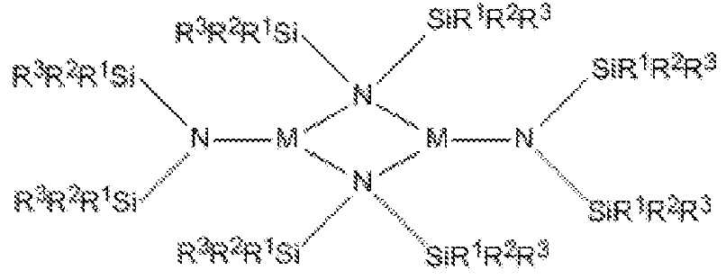
(상기 식에서, M은 Mn이며; 각 R1은 Et이며, 각 R2 및 R3은 Me임).Containing film-forming composition containing a manganese-containing film-forming composition comprising a liquid silylamide-containing precursor comprising a canister having an inlet conduit and an outlet conduit and having the formula:
(Wherein M is Mn; each R 1 is Et and each R 2 and R 3 is Me).
Applications Claiming Priority (3)
| Application Number | Priority Date | Filing Date | Title |
|---|---|---|---|
| US14/986,313 | 2015-12-31 | ||
| US14/986,313 US10011903B2 (en) | 2015-12-31 | 2015-12-31 | Manganese-containing film forming compositions, their synthesis, and use in film deposition |
| PCT/US2016/066120 WO2017116665A1 (en) | 2015-12-31 | 2016-12-12 | Manganese-containing film forming compositions, their synthesis, and use in film deposition |
Publications (2)
| Publication Number | Publication Date |
|---|---|
| KR20180098579A true KR20180098579A (en) | 2018-09-04 |
| KR102653070B1 KR102653070B1 (en) | 2024-03-29 |
Family
ID=56286180
Family Applications (1)
| Application Number | Title | Priority Date | Filing Date |
|---|---|---|---|
| KR1020187020025A Active KR102653070B1 (en) | 2015-12-31 | 2016-12-12 | Manganese-containing film-forming compositions, synthesis thereof, and use in film deposition |
Country Status (6)
| Country | Link |
|---|---|
| US (1) | US10011903B2 (en) |
| EP (1) | EP3397789B1 (en) |
| JP (1) | JP6941610B2 (en) |
| KR (1) | KR102653070B1 (en) |
| CN (1) | CN108474113A (en) |
| WO (1) | WO2017116665A1 (en) |
Cited By (1)
| Publication number | Priority date | Publication date | Assignee | Title |
|---|---|---|---|---|
| KR20180098578A (en) * | 2015-12-31 | 2018-09-04 | 레르 리키드 쏘시에떼 아노님 뿌르 레?드 에렉스뿔라따시옹 데 프로세데 조르즈 클로드 | Cobalt-containing film-forming composition, its synthesis, and its use in film deposition |
Families Citing this family (3)
| Publication number | Priority date | Publication date | Assignee | Title |
|---|---|---|---|---|
| EP3282037B1 (en) | 2016-08-09 | 2022-12-07 | IMEC vzw | Formation of a transition metal nitride |
| CN111748794A (en) * | 2019-03-26 | 2020-10-09 | 江苏迈纳德微纳技术有限公司 | Manganese dioxide nano composite film material and preparation method thereof |
| WO2020255913A1 (en) * | 2019-06-17 | 2020-12-24 | 田中貴金属工業株式会社 | Starting material for chemical vapor deposition composed of organic manganese compound, and chemical vapor deposition method using said starting material for chemical vapor deposition |
Citations (5)
| Publication number | Priority date | Publication date | Assignee | Title |
|---|---|---|---|---|
| US6984591B1 (en) * | 2000-04-20 | 2006-01-10 | International Business Machines Corporation | Precursor source mixtures |
| KR20100017170A (en) * | 2007-05-21 | 2010-02-16 | 레르 리키드 쏘시에떼 아노님 뿌르 레드 에렉스뿔라따시옹 데 프로세데 조르즈 클로드 | New metal precursors for semiconductor applications |
| KR20100017171A (en) * | 2007-05-21 | 2010-02-16 | 레르 리키드 쏘시에떼 아노님 뿌르 레드 에렉스뿔라따시옹 데 프로세데 조르즈 클로드 | New cobalt precursors for semiconductor applications |
| KR20140016322A (en) * | 2011-03-11 | 2014-02-07 | 우베 고산 가부시키가이샤 | Polyimide precursor and polyimide |
| KR20150122659A (en) * | 2013-02-28 | 2015-11-02 | 어플라이드 머티어리얼스, 인코포레이티드 | Metal amide deposition precursors and their stabilization with an inert ampoule liner |
Family Cites Families (7)
| Publication number | Priority date | Publication date | Assignee | Title |
|---|---|---|---|---|
| US6969539B2 (en) | 2000-09-28 | 2005-11-29 | President And Fellows Of Harvard College | Vapor deposition of metal oxides, silicates and phosphates, and silicon dioxide |
| US9051641B2 (en) | 2001-07-25 | 2015-06-09 | Applied Materials, Inc. | Cobalt deposition on barrier surfaces |
| US7033560B2 (en) | 2002-08-30 | 2006-04-25 | Air Products And Chemicals, Inc. | Single source mixtures of metal siloxides |
| US20090087561A1 (en) * | 2007-09-28 | 2009-04-02 | Advanced Technology Materials, Inc. | Metal and metalloid silylamides, ketimates, tetraalkylguanidinates and dianionic guanidinates useful for cvd/ald of thin films |
| US9005704B2 (en) | 2013-03-06 | 2015-04-14 | Applied Materials, Inc. | Methods for depositing films comprising cobalt and cobalt nitrides |
| US9362228B2 (en) | 2013-10-22 | 2016-06-07 | Globalfoundries Inc. | Electro-migration enhancing method for self-forming barrier process in copper metalization |
| JP2019500495A (en) * | 2015-12-02 | 2019-01-10 | ビーエーエスエフ ソシエタス・ヨーロピアBasf Se | Method for producing thin inorganic film |
-
2015
- 2015-12-31 US US14/986,313 patent/US10011903B2/en active Active
-
2016
- 2016-12-12 CN CN201680076757.6A patent/CN108474113A/en active Pending
- 2016-12-12 EP EP16882292.2A patent/EP3397789B1/en active Active
- 2016-12-12 WO PCT/US2016/066120 patent/WO2017116665A1/en not_active Ceased
- 2016-12-12 KR KR1020187020025A patent/KR102653070B1/en active Active
- 2016-12-12 JP JP2018530084A patent/JP6941610B2/en active Active
Patent Citations (5)
| Publication number | Priority date | Publication date | Assignee | Title |
|---|---|---|---|---|
| US6984591B1 (en) * | 2000-04-20 | 2006-01-10 | International Business Machines Corporation | Precursor source mixtures |
| KR20100017170A (en) * | 2007-05-21 | 2010-02-16 | 레르 리키드 쏘시에떼 아노님 뿌르 레드 에렉스뿔라따시옹 데 프로세데 조르즈 클로드 | New metal precursors for semiconductor applications |
| KR20100017171A (en) * | 2007-05-21 | 2010-02-16 | 레르 리키드 쏘시에떼 아노님 뿌르 레드 에렉스뿔라따시옹 데 프로세데 조르즈 클로드 | New cobalt precursors for semiconductor applications |
| KR20140016322A (en) * | 2011-03-11 | 2014-02-07 | 우베 고산 가부시키가이샤 | Polyimide precursor and polyimide |
| KR20150122659A (en) * | 2013-02-28 | 2015-11-02 | 어플라이드 머티어리얼스, 인코포레이티드 | Metal amide deposition precursors and their stabilization with an inert ampoule liner |
Cited By (1)
| Publication number | Priority date | Publication date | Assignee | Title |
|---|---|---|---|---|
| KR20180098578A (en) * | 2015-12-31 | 2018-09-04 | 레르 리키드 쏘시에떼 아노님 뿌르 레?드 에렉스뿔라따시옹 데 프로세데 조르즈 클로드 | Cobalt-containing film-forming composition, its synthesis, and its use in film deposition |
Also Published As
| Publication number | Publication date |
|---|---|
| WO2017116665A1 (en) | 2017-07-06 |
| KR102653070B1 (en) | 2024-03-29 |
| EP3397789A4 (en) | 2019-08-14 |
| EP3397789A1 (en) | 2018-11-07 |
| JP6941610B2 (en) | 2021-09-29 |
| CN108474113A (en) | 2018-08-31 |
| US10011903B2 (en) | 2018-07-03 |
| US20160194755A1 (en) | 2016-07-07 |
| JP2019500497A (en) | 2019-01-10 |
| EP3397789B1 (en) | 2020-09-02 |
Similar Documents
| Publication | Publication Date | Title |
|---|---|---|
| US11168099B2 (en) | Titanium-containing film forming compositions for vapor deposition of titanium-containing films | |
| TW201638098A (en) | Vapor deposition method for forming a ruthenium-containing and oxygen-containing film | |
| US10584039B2 (en) | Titanium-containing film forming compositions for vapor deposition of titanium-containing films | |
| CN110073474B (en) | Zirconium precursors, hafnium precursors, titanium precursors and their use to deposit Group 4-containing films | |
| US20170152144A1 (en) | Niobium-nitride film forming compositions and vapor deposition of niobium-nitride films | |
| KR102514164B1 (en) | Deposition of zirconium, hafnium, and titanium precursors and group 4-containing films using the same | |
| KR102653070B1 (en) | Manganese-containing film-forming compositions, synthesis thereof, and use in film deposition | |
| KR102653603B1 (en) | Cobalt-containing film-forming compositions, synthesis thereof, and use in film deposition | |
| US20160083405A1 (en) | Tantalum- or vanadium-containing film forming compositions and vapor deposition of tantalum- or vanadium-containing films | |
| US20210221830A1 (en) | Methods for vapor deposition of group 4 transition metal-containing films using group 4 transition metal-containing films forming compositions | |
| US9790591B2 (en) | Titanium-containing film forming compositions for vapor deposition of titanium-containing films | |
| US9738971B2 (en) | Vapor deposition methods to form group 8-containing films |
Legal Events
| Date | Code | Title | Description |
|---|---|---|---|
| PA0105 | International application |
Patent event date: 20180712 Patent event code: PA01051R01D Comment text: International Patent Application |
|
| PG1501 | Laying open of application | ||
| A201 | Request for examination | ||
| PA0201 | Request for examination |
Patent event code: PA02012R01D Patent event date: 20211124 Comment text: Request for Examination of Application |
|
| E902 | Notification of reason for refusal | ||
| PE0902 | Notice of grounds for rejection |
Comment text: Notification of reason for refusal Patent event date: 20230720 Patent event code: PE09021S01D |
|
| E701 | Decision to grant or registration of patent right | ||
| PE0701 | Decision of registration |
Patent event code: PE07011S01D Comment text: Decision to Grant Registration Patent event date: 20240126 |
|
| GRNT | Written decision to grant | ||
| PR0701 | Registration of establishment |
Comment text: Registration of Establishment Patent event date: 20240327 Patent event code: PR07011E01D |
|
| PR1002 | Payment of registration fee |
Payment date: 20240327 End annual number: 3 Start annual number: 1 |
|
| PG1601 | Publication of registration |