KR20180098571A - Gas discharge tube - Google Patents
Gas discharge tube Download PDFInfo
- Publication number
- KR20180098571A KR20180098571A KR1020187019069A KR20187019069A KR20180098571A KR 20180098571 A KR20180098571 A KR 20180098571A KR 1020187019069 A KR1020187019069 A KR 1020187019069A KR 20187019069 A KR20187019069 A KR 20187019069A KR 20180098571 A KR20180098571 A KR 20180098571A
- Authority
- KR
- South Korea
- Prior art keywords
- gas discharge
- discharge tube
- electrode
- low temperature
- sealing joint
- Prior art date
- Legal status (The legal status is an assumption and is not a legal conclusion. Google has not performed a legal analysis and makes no representation as to the accuracy of the status listed.)
- Granted
Links
- 238000007789 sealing Methods 0.000 claims abstract description 134
- 238000002844 melting Methods 0.000 claims abstract description 24
- 230000008018 melting Effects 0.000 claims abstract description 24
- 239000010410 layer Substances 0.000 claims description 63
- 238000009413 insulation Methods 0.000 claims description 43
- 229910052751 metal Inorganic materials 0.000 claims description 32
- 239000002184 metal Substances 0.000 claims description 32
- 238000000926 separation method Methods 0.000 claims description 22
- 238000000034 method Methods 0.000 claims description 21
- 239000011241 protective layer Substances 0.000 claims description 15
- 238000001465 metallisation Methods 0.000 claims description 9
- PXHVJJICTQNCMI-UHFFFAOYSA-N Nickel Chemical group [Ni] PXHVJJICTQNCMI-UHFFFAOYSA-N 0.000 claims description 8
- 239000012212 insulator Substances 0.000 claims description 5
- VYZAMTAEIAYCRO-UHFFFAOYSA-N Chromium Chemical compound [Cr] VYZAMTAEIAYCRO-UHFFFAOYSA-N 0.000 claims description 4
- 229910052804 chromium Inorganic materials 0.000 claims description 4
- 239000011651 chromium Substances 0.000 claims description 4
- 229910052759 nickel Inorganic materials 0.000 claims description 4
- 229910052755 nonmetal Inorganic materials 0.000 claims description 4
- 239000011236 particulate material Substances 0.000 claims description 4
- 230000000903 blocking effect Effects 0.000 abstract description 2
- 239000007789 gas Substances 0.000 description 168
- 229910000679 solder Inorganic materials 0.000 description 27
- 239000000853 adhesive Substances 0.000 description 10
- 230000001070 adhesive effect Effects 0.000 description 10
- 230000000694 effects Effects 0.000 description 7
- 239000000155 melt Substances 0.000 description 7
- 238000005476 soldering Methods 0.000 description 7
- 238000009423 ventilation Methods 0.000 description 5
- VYPSYNLAJGMNEJ-UHFFFAOYSA-N Silicium dioxide Chemical compound O=[Si]=O VYPSYNLAJGMNEJ-UHFFFAOYSA-N 0.000 description 4
- 239000013618 particulate matter Substances 0.000 description 4
- 239000000919 ceramic Substances 0.000 description 3
- 238000009434 installation Methods 0.000 description 3
- 239000000463 material Substances 0.000 description 3
- ATJFFYVFTNAWJD-UHFFFAOYSA-N Tin Chemical compound [Sn] ATJFFYVFTNAWJD-UHFFFAOYSA-N 0.000 description 2
- PCEXQRKSUSSDFT-UHFFFAOYSA-N [Mn].[Mo] Chemical group [Mn].[Mo] PCEXQRKSUSSDFT-UHFFFAOYSA-N 0.000 description 2
- 239000011248 coating agent Substances 0.000 description 2
- 238000000576 coating method Methods 0.000 description 2
- 238000009713 electroplating Methods 0.000 description 2
- 239000003292 glue Substances 0.000 description 2
- 230000007257 malfunction Effects 0.000 description 2
- 239000000843 powder Substances 0.000 description 2
- RYGMFSIKBFXOCR-UHFFFAOYSA-N Copper Chemical group [Cu] RYGMFSIKBFXOCR-UHFFFAOYSA-N 0.000 description 1
- 239000006004 Quartz sand Substances 0.000 description 1
- 238000010521 absorption reaction Methods 0.000 description 1
- 230000009286 beneficial effect Effects 0.000 description 1
- 230000015556 catabolic process Effects 0.000 description 1
- 238000006243 chemical reaction Methods 0.000 description 1
- 238000005352 clarification Methods 0.000 description 1
- 229910052802 copper Inorganic materials 0.000 description 1
- 239000010949 copper Substances 0.000 description 1
- 238000010891 electric arc Methods 0.000 description 1
- 230000002708 enhancing effect Effects 0.000 description 1
- 239000011521 glass Substances 0.000 description 1
- 230000017525 heat dissipation Effects 0.000 description 1
- 230000020169 heat generation Effects 0.000 description 1
- 239000011261 inert gas Substances 0.000 description 1
- 238000013021 overheating Methods 0.000 description 1
- 239000002245 particle Substances 0.000 description 1
- 229910052573 porcelain Inorganic materials 0.000 description 1
- 238000004064 recycling Methods 0.000 description 1
- 239000004576 sand Substances 0.000 description 1
- 239000012945 sealing adhesive Substances 0.000 description 1
- 239000003566 sealing material Substances 0.000 description 1
- 239000000377 silicon dioxide Substances 0.000 description 1
- XLYOFNOQVPJJNP-UHFFFAOYSA-N water Substances O XLYOFNOQVPJJNP-UHFFFAOYSA-N 0.000 description 1
Images


Classifications
-
- H—ELECTRICITY
- H01—ELECTRIC ELEMENTS
- H01J—ELECTRIC DISCHARGE TUBES OR DISCHARGE LAMPS
- H01J17/00—Gas-filled discharge tubes with solid cathode
- H01J17/02—Details
- H01J17/18—Seals between parts of vessels; Seals for leading-in conductors; Leading-in conductors
- H01J17/186—Seals between leading-in conductors and vessel
-
- H—ELECTRICITY
- H01—ELECTRIC ELEMENTS
- H01T—SPARK GAPS; OVERVOLTAGE ARRESTERS USING SPARK GAPS; SPARKING PLUGS; CORONA DEVICES; GENERATING IONS TO BE INTRODUCED INTO NON-ENCLOSED GASES
- H01T1/00—Details of spark gaps
- H01T1/15—Details of spark gaps for protection against excessive pressure
-
- H—ELECTRICITY
- H01—ELECTRIC ELEMENTS
- H01J—ELECTRIC DISCHARGE TUBES OR DISCHARGE LAMPS
- H01J17/00—Gas-filled discharge tubes with solid cathode
- H01J17/02—Details
- H01J17/18—Seals between parts of vessels; Seals for leading-in conductors; Leading-in conductors
-
- H—ELECTRICITY
- H01—ELECTRIC ELEMENTS
- H01J—ELECTRIC DISCHARGE TUBES OR DISCHARGE LAMPS
- H01J17/00—Gas-filled discharge tubes with solid cathode
- H01J17/02—Details
- H01J17/04—Electrodes; Screens
-
- H—ELECTRICITY
- H01—ELECTRIC ELEMENTS
- H01J—ELECTRIC DISCHARGE TUBES OR DISCHARGE LAMPS
- H01J17/00—Gas-filled discharge tubes with solid cathode
- H01J17/02—Details
- H01J17/16—Vessels; Containers
-
- H—ELECTRICITY
- H01—ELECTRIC ELEMENTS
- H01J—ELECTRIC DISCHARGE TUBES OR DISCHARGE LAMPS
- H01J17/00—Gas-filled discharge tubes with solid cathode
- H01J17/38—Cold-cathode tubes
- H01J17/40—Cold-cathode tubes with one cathode and one anode, e.g. glow tubes, tuning-indicator glow tubes, voltage-stabiliser tubes, voltage-indicator tubes
-
- H—ELECTRICITY
- H01—ELECTRIC ELEMENTS
- H01J—ELECTRIC DISCHARGE TUBES OR DISCHARGE LAMPS
- H01J61/00—Gas-discharge or vapour-discharge lamps
- H01J61/02—Details
- H01J61/30—Vessels; Containers
-
- H—ELECTRICITY
- H01—ELECTRIC ELEMENTS
- H01J—ELECTRIC DISCHARGE TUBES OR DISCHARGE LAMPS
- H01J9/00—Apparatus or processes specially adapted for the manufacture, installation, removal, maintenance of electric discharge tubes, discharge lamps, or parts thereof; Recovery of material from discharge tubes or lamps
- H01J9/24—Manufacture or joining of vessels, leading-in conductors or bases
- H01J9/26—Sealing together parts of vessels
- H01J9/265—Sealing together parts of vessels specially adapted for gas-discharge tubes or lamps
-
- H—ELECTRICITY
- H01—ELECTRIC ELEMENTS
- H01T—SPARK GAPS; OVERVOLTAGE ARRESTERS USING SPARK GAPS; SPARKING PLUGS; CORONA DEVICES; GENERATING IONS TO BE INTRODUCED INTO NON-ENCLOSED GASES
- H01T4/00—Overvoltage arresters using spark gaps
- H01T4/10—Overvoltage arresters using spark gaps having a single gap or a plurality of gaps in parallel
- H01T4/12—Overvoltage arresters using spark gaps having a single gap or a plurality of gaps in parallel hermetically sealed
-
- H—ELECTRICITY
- H01—ELECTRIC ELEMENTS
- H01J—ELECTRIC DISCHARGE TUBES OR DISCHARGE LAMPS
- H01J2893/00—Discharge tubes and lamps
- H01J2893/0048—Tubes with a main cathode
- H01J2893/0051—Anode assemblies; screens for influencing the discharge
- H01J2893/0053—Leading in for anodes; Protecting means for anode supports
-
- H—ELECTRICITY
- H01—ELECTRIC ELEMENTS
- H01T—SPARK GAPS; OVERVOLTAGE ARRESTERS USING SPARK GAPS; SPARKING PLUGS; CORONA DEVICES; GENERATING IONS TO BE INTRODUCED INTO NON-ENCLOSED GASES
- H01T1/00—Details of spark gaps
- H01T1/02—Means for extinguishing arc
- H01T1/08—Means for extinguishing arc using flow of arc-extinguishing fluid
-
- H—ELECTRICITY
- H01—ELECTRIC ELEMENTS
- H01T—SPARK GAPS; OVERVOLTAGE ARRESTERS USING SPARK GAPS; SPARKING PLUGS; CORONA DEVICES; GENERATING IONS TO BE INTRODUCED INTO NON-ENCLOSED GASES
- H01T4/00—Overvoltage arresters using spark gaps
- H01T4/16—Overvoltage arresters using spark gaps having a plurality of gaps arranged in series
Landscapes
- Engineering & Computer Science (AREA)
- Manufacturing & Machinery (AREA)
- Fuses (AREA)
- Emergency Protection Circuit Devices (AREA)
- Gas-Filled Discharge Tubes (AREA)
Abstract
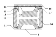
적어도 두 개의 전극(11) 및 상기 전극(11)에 밀봉 연결되어 방전 내부챔버(16)를 형성하는 전연관체(12)를 포함하는 가스 방전관(1)에 있어서, 상기 가스 방전관(1)에는 상기 방전 내부챔버(16)를 밀봉하는 저온 밀봉 접합물(13)이 마련되며, 상기 저온 밀봉 접합물(13)은 특정된 저온에서 용융됨으로써 상기 방전 내부챔버(16)를 가스 누설시킨다. 상기 가스 방전관(1)은 벼락을 맞거나, 서지(surge) 과전압을 받을 때 번개 전류 또는 과전압을 방출하는 역할을 하며; 또한, 일정한 지속적인 상용 주파수 전류 또는 과대 상용 주파수 전류가 흘러 발열로 인해 상기 저온 밀봉 접합물(13)이 용융될 때까지 온도가 상승할 경우, 해당 가스 방전관(1)은 가스 누설이 발생하여 개로됨으로써 후속의 과전류를 신속히 차단한다.A gas discharge tube (1) comprising at least two electrodes (11) and a leading tube body (12) sealingly connected to the electrode (11) to form a discharge inner chamber (16) There is provided a low temperature sealing joint 13 which seals the discharge inner chamber 16 and the low temperature sealing joint 13 gas-leaks the discharge inner chamber 16 by melting at a specified low temperature. The gas discharge tube 1 serves to emit a lightning current or an overvoltage when a lightning strike or a surge voltage is applied thereto; Further, when the temperature rises until the low temperature sealing joint 13 is melted due to a constant continuous commercial frequency current or overcurrent frequency current, the gas discharge tube 1 is opened due to gas leakage Thereby rapidly blocking the subsequent overcurrent.
Description
본 발명은 과전압 보호(overvoltage protection) 제품 영역에 관한 것으로, 특히 가스 방전관에 관한 것이다.The present invention relates to an overvoltage protection product area, and more particularly to a gas discharge tube.
가스 방전관은 스위치형 보호소자로서 통상적으로 과전압 보호소자로 사용된다. 종래에 일반적으로 사용되는 가스 방전관은 절연관체 및 그 양단의 실링 전극으로 이루어지며, 내부챔버에는 불활성 기체가 충진된다. 가스 방전관 전극 양단의 전압이 기체의 브레이크다운 전압(breakdown voltage)를 초과하면 갭 방전(gap discharge)을 일으키고, 해당 가스 방전관은 신속히 하이 임피던스(high impedance)에서 로 임피던스(low impedance)로 변하며 도통이 형성되어 이와 병열된 기타 소자를 보호할 수 있다.The gas discharge tube is a switched type protection element and is normally used as an overvoltage protection element. Conventionally, a gas discharge tube generally used is composed of an insulating tube and sealing electrodes at both ends thereof, and an inert gas is filled in the inner chamber. If the voltage across the gas discharge tube electrode exceeds a breakdown voltage of the gas, a gap discharge is caused and the gas discharge tube rapidly changes from a high impedance to a low impedance, It is possible to protect other devices formed and arranged thereon.
그러나 이와 동시에, 해당 과전압의 지속시간이 길거나 발생하는 빈도가 비교적 높은 경우, 또는 장시간 동안 대전류(high current)의 상용 주파수 과전류가 발생하는 경우, 가스 방전관은 장시간 또는 빈번히 발생하는 과전류로 인해 발열하여 승온하게 되는데, 지나치게 높은 온도는 회로 중 기타 소자의 안전한 사용에 영향을 미칠뿐만 아니라, 해당 가스 방전관이 단락 또는 터지는 위험이 존재하게 하며, 심지어 고객의 회로기판을 태워 화재를 일으킬 수도 있다.At the same time, however, when the overvoltage has a long duration or a relatively high frequency, or when a high frequency overcurrent occurs at a high current for a long time, the gas discharge tube generates heat due to an overcurrent for a long time or frequently, Excessively high temperatures affect the safe use of other components in the circuit, as well as the risk that the gas discharge tube will short circuit or explode, or even burn your circuit board to cause a fire.
본 발명은 회로에 효과적인 과전압 보호를 제공할 뿐만 아니라, 과전류로 인해 승온 시 개로(open circuit)를 형성하여 곧바로 회로를 차단할 수 있는 가스 방전관을 제공하는 것을 목적으로 한다.It is an object of the present invention to provide a gas discharge tube which not only provides effective overvoltage protection to a circuit but also can open circuit at an elevated temperature due to an overcurrent to immediately shut off the circuit.
이를 감안하여, 본 발명의 실시예에서는 적어도 두 개의 전극 및 상기 전극에 밀봉 연결되어 방전 내부챔버를 형성하는 전연관체를 포함하는 가스 방전관을 제공하며, 상기 가스 방전관에는 상기 방전 내부챔버를 밀봉하는 저온 밀봉 접합물이 마련되고, 상기 저온 밀봉 접합물은 특정된 저온에서 용융됨으로써 상기 방전 내부챔버가 가스 누설되도록 개로를 형성한다.In view of this, in an embodiment of the present invention, there is provided a gas discharge tube including at least two electrodes and a leading-edge tube sealingly connected to the electrode to form a discharge inner chamber, wherein the gas discharge tube has a low temperature A sealing joint is provided, and the low-temperature sealing joint forms an opening so that the discharge inner chamber is leaked by melting at a specified low temperature.
더 나아가, 적어도 하나의 상기 전극에는 축 방향 통기홀이 마련되고, 상기 통기홀의 내단부는 상기 방전 내부챔버에 연결되며 상기 통기홀의 외단부는 상기 저온 밀봉 접합물을 통해 커버 플레이트에 연결된다.Further, at least one of the electrodes is provided with an axial vent hole, the inner end of the vent hole is connected to the discharge inner chamber, and the outer end of the vent hole is connected to the cover plate through the low temperature sealing joint.
더 나아가, 적어도 하나의 상기 전극에는 반경방향 통기홀이 마련되고 상기 반경방향 통기홀의 적어도 하나의 포트는 상기 방전 내부챔버에 연결되며, 상기 반경방향 통기홀은 상기 전극 외부면의 요입홈을 통과하며 상기 요입홈 상면에는 상기 요입홈을 커버하는 커버 플레이트가 마련되며, 상기 커버 플레이트는 상기 저온 밀봉 접합물을 통해 상기 전극 외부면에 연결된다.Further, at least one of the electrodes is provided with a radial vent hole and at least one port of the radial vent hole is connected to the discharge inner chamber, and the radial vent hole passes through the groove of the outer surface of the electrode The upper surface of the concave groove is provided with a cover plate covering the concave groove, and the cover plate is connected to the outer surface of the electrode through the low temperature sealing joint.
더 나아가, 상기 절연관체에는 통기홀이 마련되고 상기 통기홀의 외단부는 상기 저온 밀봉 접합물을 통해 커버 플레이트에 연결된다.Furthermore, the insulation tube is provided with a vent hole and an outer end of the vent hole is connected to the cover plate through the low temperature sealing joint.
더 나아가, 상기 절연관체에는 상기 절연관체가 반경반향에서 두 부분으로 분리되도록 분리층이 마련되며, 상기 저온 밀봉 접합물은 상기 분리층에 마련되어 두 부분으로 분리된 두 개의 절연관체를 밀봉 연결시킨다.Further, the insulation tube is provided with a separation layer such that the insulation tube is separated into two parts in the radial direction, and the low temperature sealing joint is provided in the separation layer to seal the two insulation tubes separated into two parts.
더 나아가, 상기 가스 방전관의 중간 전극에는 상기 중간 전극이 두 부분으로 분리되도록 분리층이 마련되며, 상기 저온 밀봉 접합물은 상기 분리층에 마련되어 두 부분으로 분리된 상기 중간 전극을 밀봉 연결시킨다.Furthermore, the intermediate electrode of the gas discharge tube is provided with a separation layer such that the intermediate electrode is divided into two parts, and the low temperature sealing joint is provided in the separation layer to seal the intermediate electrode separated into two parts.
더 나아가, 적어도 하나의 상기 전극과 상기 절연관체 사이는 저온 밀봉 접합물을 사용하여 밀봉 연결시킨다.Furthermore, at least one of the electrodes and the insulation tube is sealed using a low-temperature sealing joint.
더 나아가, 상기 적어도 하나의 상기 전극과 상기 절연관체 사이는 저온 밀봉 접합물을 사용하여 밀봉 연결시키는 것은, 상기 전극과 상기 절연관체 사이에는 금속화층 또는 금속링이 마련되어, 상기 전극과 상기 금속화층 또는 상기 금속링 사이는 저온 밀봉 접합물을 사용하여 밀봉 연결시키는 것을 포함한다.Further, the at least one electrode and the insulating tube are sealed using a low-temperature sealing joint, and a metallization layer or a metal ring is provided between the electrode and the insulation tube, The metal rings include sealingly connecting using a low temperature seal joint.
더 나아가, 상기 가스 방전관은 적어도 하나의 자유단을 구비하는 스프링 장치를 더 포함하고, 해당 자유단은 상기 저온 밀봉 접합물과 접착된 전극에 의해 수축된 상태로 가압되며, 상기 저온 밀봉 접합물이 용융될 경우, 상기 자유단이 상기 전극에 대한 반작용력이 상기 전극과 상기 저온 밀봉 접합물 사이의 접착력보다 커져 해당 자유단은 신장되어 상기 저온 밀봉 접합물과 접착된 전극을 밀어낸다.Further, the gas discharge tube further comprises a spring device having at least one free end, the free end being pressed in a contracted state by an electrode bonded to the low temperature seal joint, and the low temperature seal joint When melted, the reaction force of the free end on the electrode is larger than the adhesion force between the electrode and the low-temperature sealing joint, so that the free end is stretched to push out the electrode adhered to the low-temperature sealing joint.
더 나아가, 상기 가스 방전관은 각 상기 전극과 각각 연결되는 핀 및 상기 스프링 장치를 수용하는 캐비티를 구비하는 하우징을 더 포함하며, 상기 캐비티는 외부 공기와 서로 연통되는 관통홀이 더 마련되며 적어도 하나의 상기 핀은 상기 관통홀에서 부터 연장되어 나온다.Further, the gas discharge tube may further include a housing having a fin connected to each of the electrodes and a cavity for receiving the spring device, wherein the cavity further includes a through hole communicating with the outside air, The pin extends out from the through hole.
더 나아가,상기 저온 밀봉 접합물은 특정 형태로 설치됨으로써 상기 저온 밀봉 접합물이 특정 용융 요구를 충족시킨다.Further, the low-temperature seal joint is installed in a specific form so that the low-temperature seal joint meets a specific melting requirement.
더 나아가, 상기 전극, 상기 저온 밀봉 접합물, 또는 상기 절연관체에는 리키네스 포인트가 설치되어, 상기 저온 밀봉 접합물은 상기 리키네스 포인트의 위치에서 다른 위치에서보다 상대적으로 더 쉽게 용융된다.Furthermore, the electrode, the low-temperature sealing joint, or the insulation tube is provided with a liquefaction point, and the low-temperature sealing joint is relatively more easily melted at the location of the reaciness point than at other positions.
더 나아가, 사기 방전 내부챔버에는 절연 입자상 물질이 충진된다.Furthermore, the fragile discharge inner chamber is filled with insulating particulate matter.
더 나아가, 외부와 접촉되는 상기 저온 밀봉 접합물의 외부면에는 열전도율이 상기 전극의 열전도율보다 작은 보호층이 마련된다.Furthermore, the outer surface of the low-temperature sealing joint in contact with the outside is provided with a protective layer whose thermal conductivity is smaller than the thermal conductivity of the electrode.
더 나아가, 상기 보호층은 니켈층, 크롬층, 기타 금속층 또는 비금속층이다.Further, the protective layer is a nickel layer, a chromium layer, or other metal layer or nonmetal layer.
본 발명의 실시예에 의해 제공된 가스 방전관은, 벼락으로 인한 과전압을 받았을 경우 과전압 보호 성능을 발휘할 수 있고; 또한 과대전류 또는 장시간의 과전류가 흘러 발열로 인해 상기 저온 밀봉 접합물이 용융될 때까지 온도가 상승할 경우, 해당 가스 방전관은 가스 누설이 발생하여 개로(open circuit)됨으로써 과전류를 차단하며, 양호한 과전압과 과전류 보호 성능을 구비한다.The gas discharge tube provided by the embodiment of the present invention can exhibit the overvoltage protection performance when the overvoltage due to the lightning strikes is received; Further, when the temperature rises due to excessive current or over-current flowing for a long time due to heat generation, the gas discharge tube is open-circuited due to gas leakage to cut off the overcurrent, And overcurrent protection.
본 출원의 실시예 또는 종래 기술에서의 기술방안을 더욱 명확하게 설명하기 위하여, 아래에서는 실시예 또는 종래 기술에 대한 서술에서 사용하게 될 도면에 대하여 간단한 설명을 하며, 바람직하게, 아래에서 서술하는 도면은 단지 본 출원의 일부 실시예이며, 본 분야 통상의 당업자는 진보성 노동을 부여하지 않는 전제하에서, 이러한 도면에 따라 기타 도면을 얻을 수도 있다.
도 1은 본 발명의 실시예 1에 의해 제공된 가스 방전관의 축 방향 단면도이다.
도 2는 본 발명의 실시예 2에 의해 제공된 가스 방전관의 축 방향 단면도이다.
도 3은 본 발명의 실시예 3에 의해 제공된 가스 방전관의 축 방향 단면도이다.
도 4는 본 발명의 실시예 4에 의해 제공된 가스 방전관의 축 방향 단면도이다.
도 5는 본 발명의 실시예 5에 의해 제공된 가스 방전관의 축 방향 단면도이다.
도 6은 본 발명의 실시예 6에 의해 제공된 가스 방전관의 축 방향 단면도이다.
도 7은 본 발명의 실시예 7에 의해 제공된 가스 방전관의 축 방향 단면도이다.
도 8은 본 발명의 실시예 8에 의해 제공된 가스 방전관의 축 방향 단면도이다.
도 9는 본 발명의 실시예 9에 의해 제공된 가스 방전관의 축 방향 단면도이다.
도 10은 본 발명의 실시예 7에 의해 제공된 가스 방전관의 저온 밀봉(sealing) 접합물의 횡단면도이다.
도 11은 본 발명의 실시예 8에 의해 제공된 제 1 바람직한 방안의 가스 방전관의 축 방향 단면도이다.
도 12는 본 발명의 실시예 8에 의해 제공된 제 2 바람직한 방안의 가스 방전관의 축 방향 단면도이다.
도 13은 본 발명의 실시예 8에 의해 제공된 제 3 바람직한 방안의 가스 방전관의 축 방향 단면도이다.
도 14는 본 발명의 실시예 8에 의해 제공된 제 4 바람직한 방안의 가스 방전관의 축 방향 단면도이다.
도 15는 본 발명의 실시예 8에 의해 제공된 제 5 바람직한 방안의 가스 방전관의 축 방향 단면도이다.
도 16은 본 발명의 실시예 7에 의해 제공된 제 1 바람직한 방안의 가스 방전관의 축 방향 단면도이다.
도 17은 본 발명의 실시예 7에 의해 제공된 제 2 바람직한 방안의 가스 방전관의 축 방향 단면도이다.BRIEF DESCRIPTION OF THE DRAWINGS The above and other objects, features and advantages of the present invention will become more apparent from the following detailed description of the present invention when taken in conjunction with the accompanying drawings, Are merely some embodiments of the present application and those skilled in the art will be able to obtain other drawings in accordance with these drawings under the premise that they do not confer liberty labor.
1 is an axial cross-sectional view of a gas discharge tube provided by
2 is an axial sectional view of the gas discharge tube provided by
3 is an axial cross-sectional view of the gas discharge tube provided by
4 is an axial sectional view of the gas discharge tube provided by
5 is an axial sectional view of the gas discharge tube provided by
6 is an axial cross-sectional view of the gas discharge tube provided by
7 is an axial sectional view of the gas discharge tube provided by Embodiment 7 of the present invention.
8 is an axial sectional view of the gas discharge tube provided by
9 is an axial sectional view of the gas discharge tube provided by the ninth embodiment of the present invention.
10 is a cross-sectional view of a low-temperature sealing joint of the gas discharge tube provided by Embodiment 7 of the present invention.
11 is an axial cross-sectional view of the gas discharge tube of the first preferred embodiment provided by Example 8 of the present invention.
12 is an axial sectional view of the gas discharge tube of the second preferred embodiment provided by Example 8 of the present invention.
13 is an axial sectional view of the gas discharge tube of the third preferred embodiment provided by the eighth embodiment of the present invention.
14 is an axial cross-sectional view of a gas discharge tube according to a fourth preferred embodiment provided by Embodiment 8 of the present invention.
15 is an axial cross-sectional view of a gas discharge tube according to a fifth preferred embodiment provided by Example 8 of the present invention.
16 is an axial cross-sectional view of the gas discharge tube of the first preferred embodiment provided by Example 7 of the present invention.
17 is an axial cross-sectional view of the gas discharge tube of the second preferred embodiment provided by Example 7 of the present invention.
본 발명의 실시를 위한 최선의 형태BEST MODE FOR CARRYING OUT THE INVENTION
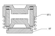
도 12는 본 발명의 가장 바람직한 실시예의 가스 방전관의 축 방향 단면도이며 도 12의 도시를 참조하도록 한다. 도 12에서 나타낸 가스 방전관과 도 8에서 나타낸 가스 방전관은 전극, 절연관체, 저온 밀봉 접합물, 금속링 및 고온 솔더층을 포함하는 방면에서 동일하고; 도 8에서 나타낸 가스 방전관과의 차이점은, 도 12에서 나타낸 가스 방전관이 하나의 자유단(871)을 구비하는 스프링 장치(87)를 더 포함하는 것이다. 상기 자유단(871)은 상기 저온 밀봉 접합물과 접착된 전극에 의해 수축된 상태로 가압되고, 상기 저온 밀봉 접합물이 용융될 경우, 해당 자유단(871)이 상기 전극에 대한 반작용력이 상기 전극과 상기 저온 밀봉 접합물 사이의 접착력보다 커져 해당 자유단(871)은 신장되어 상기 저온 밀봉 접합물과 접착된 전극을 밀어낸다. 마찬가지로, 상기 가스 방전관 양단이 모두 저온 밀봉 접합물이 설치되는 경우, 상기 스프링 장치에는 두 개의 자유단(미도시)이 설치될 수 있으며, 어느 하나의 자유단의 저온 밀봉 접합물이 용융되기만 하면 해당 자유단은 신장되어 해당 단부의 전극이 당겨진다. 그 장점은 아래와 같다: 상기 가스 방전관에 대전류가 흐르는 경우, 상기 저온 밀봉 접합물이 용융되기 시작하여 이와 전극 사이의 접착력이 작아질 때까지 용융되면, 힘의 균형이 깨져 해당 스프링 장치는 자유단이 신장되고 상기 저온 밀봉 접합물과 접착된 전극을 신속히 밀어내 급속으로 가스 누설되어 개로되며, 이로써 회로에 대한 개로 보호 효과를 더 한층 제고한다. 이와 반대로, 스프링 장치를 설치하지 않으면, 상기 가스 방전관에 대전류가 흐르는 경우, 순간 방전열량이 지나치게 커지게 되는데, 이로 인해 상기 저온 밀봉 접합물이 용융되어 가스 누설을 일으키기도 전에, 상기 전극이 이미 용융되어 폭발하고 날리어 단락을 초래하게 된다.Fig. 12 is an axial cross-sectional view of the gas discharge tube of the most preferred embodiment of the present invention, and reference is made to Fig. 12. The gas discharge tube shown in Fig. 12 and the gas discharge tube shown in Fig. 8 are the same in the aspect including the electrode, the insulating tube, the low-temperature sealing joint, the metal ring and the high-temperature solder layer; The difference from the gas discharge tube shown in Fig. 8 is that the gas discharge tube shown in Fig. 12 further includes a spring device 87 having one free end 871. Fig. The free end (871) is pressed in a contracted state by the electrode bonded to the low temperature sealing joint, and when the low temperature sealing joint is melted, the free end (871) Is greater than the adhesive force between the electrode and the low-temperature sealing joint, and the free end 871 is stretched to push out the electrode adhered to the low-temperature sealing joint. Likewise, when both ends of the gas discharge tube are provided with low-temperature sealing joints, the spring device may be provided with two free ends (not shown). If the low- temperature sealing joints of either free end are melted, The free end is elongated and the electrode at the end is pulled. The advantages are as follows: When a large current flows through the gas discharge tube, when the low-temperature sealing joint starts to melt and melts until the adhesion between the electrodes becomes small, the balance of the force is broken, The electrode which is elongated and bonded to the low-temperature sealing joint is quickly pushed out to rapidly open the gas leakage, thereby further improving the open protection effect on the circuit. On the other hand, if a large current flows through the gas discharge tube without providing a spring device, the amount of instantaneous discharge heat becomes excessively large. As a result, before the low temperature sealing joint melts to cause gas leakage, It will explode and fly and short circuit.
본 발명의 실시형태Embodiments of the present invention
아래에서는 도면을 참조하여 하기 실시형태로 본 발명에 대해 계속하여 설명한다. 사전에 설명해야 할 것은, 본 발명에서 지칭하는 고온 솔더(high-temperature solder)는 용점이 500℃보다 높은 솔더이고, 고온은 즉 500℃보다 높은 온도를 의미하며; 본 발명에서 지칭하는 저온은 해당 고온에 비해 낮은 온도로써 500℃ 및 500℃ 이하의 온도를 의미한다. 본 발명에서 지칭하는 저온 밀봉 접합물은 저온에 견딜 수 있는 밀봉재료이고 해당 재료는 상기 저온보다 높은 환경에서 용융 변형되며 심지어 액화되어 밀봉을 실현하지 못한다. 본 발명에서 지칭하는 절연관체는 유리관, 애자관(ceramic tube) 또는 기타 가스 방전관에 적용되는 재질의 절연관체이고; 본 발명에서 지칭하는 가스 방전관은 다이오드(diode), 3극관(triode) 및 다극관(multielectrode tube)을 포함한다.Hereinafter, the present invention will be described in the following embodiments with reference to the drawings. It should be noted that the high-temperature solder referred to in the present invention is a solder having a melting point higher than 500 캜, and a high temperature means a temperature higher than 500 캜; The low temperature referred to in the present invention means a temperature lower than 500 ° C. and 500 ° C. or lower as compared with the corresponding high temperature. The low temperature sealing joint referred to in the present invention is a sealing material which can withstand low temperatures, and the material is melt-deformed in an environment higher than the low temperature, and even liquefied and does not realize sealing. The insulated tubular body referred to in the present invention is an insulated tubular material which is applied to a glass tube, a ceramic tube or other gas discharge tube; The gas discharge tube referred to in the present invention includes a diode, a triode, and a multielectrode tube.
도 1, 즉 본 발명의 실시예 1에 의해 제공된 가스 방전관의 축 방향 단면도를 참조하도록 한다. 도 1에서 나타낸 바와 같이, 본 실시예의 가스 방전관(1)은 전극(11), 절연관체(12), 저온 밀봉 접합물(13), 통기홀(14) 및 커버 플레이트(15)를 포함한다. 상기 전극(11)은 상기 절연관체(12)와 밀봉 연결되어 방전 내부챔버(16)를 형성하며 상기 통기홀(14)은 상기 전극(11)에 설치되되 축 방향에 따라 설치된다. 상기 통기홀(11)의 내단부는 상기 방전 내부 챔버(16)에 연결되고 외단부는 상기 저온 밀봉 접합물(13)을 통해 상기 커버 플레이트(15)에 연결된다.1, that is, an axial cross-sectional view of the gas discharge tube provided by the first embodiment of the present invention. 1, the
구체적으로, 상기 전극(11)과 상기 절연관체(12)는 고온 솔더(17)로 밀봉되며, 상기 고온 솔더(17)는 은동 솔더(sliver-copper solder)인 것이 바람직하다.Specifically, the
구체적으로, 상기 저온 밀봉 접합물(13)은 저온 솔더(low temperature solder) 또는 저온 접착제이다. 바람직하게, 상기 저온 솔더는 저온 주석 솔더(low-temperature tin solder) 또는 유리 솔더이고 용점은 대략 350℃이다. 상기 저온 접착제는 글루(glue) 등 유기 접착제이다.Specifically, the low
일 바람직한 실시예에서, 상기 통기홀(11)은 복수 개가 마련되되 모두 하나의 전극에 설치된다. 다른 바람직한 실시예에서, 상기 통기홀(11)은 복수 개가 마련되되 각 전극에 각각 설치된다.In one preferred embodiment, a plurality of the
또 다른 바람직한 실시예에서, 상기 저온 밀봉 접합물(13)의 상기 커버 플레이트(15)에서의 부착력을 증가시켜 밀봉효과를 더욱 향상시키기 위해, 상기 커버 플레이트(15)는 거친면 커버 플레이이트 또는 통기 요홈을 구비하는 커버 플레이트를 사용한다. 아울러, 상기 저온 밀봉 접합물(13)이 용융될 경우, 상기 방전 내부챔버(16)에서의 가스는 거친면 커버 플레이트 또는 통기 요홈을 구비하는 커버 플레이트의 간극을 통해 더욱 용이하게 누설되므로, 추후 회로를 신속하게 차단시킬 수 있다.In another preferred embodiment, in order to increase the adhesion of the low-temperature sealing joint 13 at the
본 실시예는 아래와 같은 장점을 갖는다:The present embodiment has the following advantages:
가스 방전관에는 방전 내부 챔버와 외부를 연결시키는 통기홀이 설치되고 상기 통기홀의 외단부에는 저온 밀봉 접합물이 설치된다. 따라서, 벼락으로 인한 과전압을 받을 경우, 해당 가스 방전관은 과전압 보호의 성능을 발휘할 수 있을 뿐만 아니라; 또한 해당 가스 방전관에 대전류가 흐르거나 과전류가 장시간 흘러 특정 온도까지 승온할 경우, 상기 저온 밀봉 접합물은 용점에 도달하여 용융되기 시작하며 상기 통기홀은 가스 누설이 발생하여 외부 공기가 상기 가스 방전관의 방전 내부챔버로 유입되며, 따라서 회로가 신속히 차단되어 회로의 안전을 보호할 수 있다.The gas discharge tube is provided with a vent hole for connecting the discharge inner chamber to the outside, and a low-temperature sealing joint is provided at the outer end of the vent hole. Therefore, when an overvoltage due to a lightning strike is received, the gas discharge tube can not only exhibit the overvoltage protection performance; In addition, when a large current flows through the gas discharge tube or an overcurrent flows for a long time to raise the temperature to a specific temperature, the low temperature sealing joint reaches the melting point and starts to melt, and the gas hole leaks, It enters the discharge inner chamber, and thus the circuit is quickly shut down to protect the safety of the circuit.
도 2, 즉 본 발명의 실시예 2에 의해 제공된 가스 방전관의 축 방향 단면도를 참조하도록 한다. 도 2에서 나타낸 바와 같이, 본 실시예의 가스 방전관(2)은 전극(21), 절연관체(22), 저온 밀봉 접합물(23), 통기홀(24) 및 커버 플레이트(25)를 포함한다. 도 1에서 나타낸 실시예와의 차이점은 아래와 같다: 본 실시예 중 통기홀(24)은 반경방향에 설치된 것으로 상기 반경방향 통기홀(24)의 하나의 포트(port) 또는 좌우 두 개의 포트는 상기 내부챔버에 연결되고, 상기 반경방향의 통기홀(24)은 상기 전극(21) 외부면의 요입홈을 통과하며, 상기 요입홈 상면에는 상기 요입홈을 커버하는 커버 플레이트(25)가 마련되며, 상기 커버 플레이트(25)는 상기 저온 밀봉 접합물(23)을 통해 상기 전극(21) 외부면에 연결된다. 이외의 기타 부품은 모두 도 1에서 나타낸 실시예와 동일하므로 여기서 더 설명하지 않는다.2, that is, an axial sectional view of the gas discharge tube provided by the second embodiment of the present invention will be referred to. 2, the
본 실시예는 아래와 같은 장점을 갖는다:The present embodiment has the following advantages:
가스 방전관에는 방전 내부 챔버와 외부를 연결시키는 통기홀이 설치되고 상기 통기홀의 외단부에는 저온 밀봉 접합물이 설치된다. 따라서, 벼락으로 인한 과전압을 받을 경우, 해당 가스 방전관은 과전압 보호의 성능을 발휘할 수 있을 뿐만 아니라; 또한 해당 가스 방전관에 대전류가 흐르거나 과전류가 장시간 흘러 특정 온도까지 승온할 경우, 상기 저온 밀봉 접합물은 용점에 도달하여 용융되기 시작하며 상기 통기홀은 가스 누설이 발생하여 외부 공기가 상기 가스 방전관의 방전 내부챔버로 유입되며, 따라서 회로가 신속히 차단되어 회로의 안전을 보호할 수 있다.The gas discharge tube is provided with a vent hole for connecting the discharge inner chamber to the outside, and a low-temperature sealing joint is provided at the outer end of the vent hole. Therefore, when an overvoltage due to a lightning strike is received, the gas discharge tube can not only exhibit the overvoltage protection performance; In addition, when a large current flows through the gas discharge tube or an overcurrent flows for a long time to raise the temperature to a specific temperature, the low temperature sealing joint reaches the melting point and starts to melt, and the gas hole leaks, It enters the discharge inner chamber, and thus the circuit is quickly shut down to protect the safety of the circuit.
도 3, 즉 본 발명의 실시예 3에 의해 제공된 가스 방전관의 축 방향 단면도를 참조하도록 한다. 도 3에서 나타낸 바와 같이, 본 실시예의 가스 방전관(3)은 전극(31), 절연관체(32), 저온 밀봉 접합물(33)을 포함한다.3, that is, the axial sectional view of the gas discharge tube provided by the
구체적으로, 상기 절연관체(32)의 중간에는 상기 절연관체가 반경반향에서 두 부분으로 분리되도록 분리층이 마련되며, 상기 저온 밀봉 접합물(32)은 상기 분리층에 설치되어 두 부분으로 분리된 두 개의 절연관체를 밀봉 연결시킨다. 물론, 두 개의 절연관체(32)는 상기 저온 밀봉 접합물(32)을 통해 함께 밀봉 연결되며, 그 작용 및 원리는 본 실시예 3과 동일하다는 것을 이해할 수 있다.Specifically, a separation layer is provided in the middle of the
일 바람직한 실시예에서, 상기 저온 밀봉 접합물(32)은 상기 분리층의 중간에 설치되고, 상용 주파수 전류에서 방전관이 지속적으로 아크 방전(arc discharge)할 때의 열량을 더욱 용이하게 흡수할 수 있으므로, 가스 누설에 따른 개로 실효가 쉽게 발생하여, 이로써 회로를 차단한다.In one preferred embodiment, the low temperature seal joint 32 is installed in the middle of the separation layer and can more easily absorb the amount of heat when the discharge tube continuously arc discharges at a commercial frequency current , The opening efficiency due to the gas leakage easily occurs, thereby blocking the circuit.
본 실시예의 다른 변형 가능한 실시예로서, 상기 절연관체(32)에는 통기홀(미도시)이 설치될 수도 있고, 상기 통기홀의 외단부는 상기 저온 밀봉 접합물을 통해 커버 플레이트에 연결되어 밀봉을 실현하며, 그 작용 및 원리는 여전히 본 실시예 3과 동일하다.As another variant of this embodiment, a ventilation hole (not shown) may be provided in the
본 실시예는 아래와 같은 장점을 갖는다:The present embodiment has the following advantages:
가스 방전관의 절연관체에는 저온 밀봉 접합물로 밀봉된 분리층이 설치된다. 따라서, 벼락으로 인한 과전압을 받을 시 해당 가스 방전관은 과전압 보호의 성능을 발휘할 수 있을 뿐만 아니라; 또한,The insulation tube of the gas discharge tube is provided with a separation layer sealed with a low temperature sealing joint. Accordingly, when the overvoltage due to the lightning strikes, the gas discharge tube can not only exhibit the overvoltage protection performance; Also,
해당 가스 방전관에 대전류가 흐르거나 과전류가 장시간 흘러 특정 온도까지 승온할 경우, 상기 저온 밀봉 접합물은 용점에 도달하여 용융되기 시작하며 상기 분리층에는 가스 누설이 발생하여 외부 공기가 상기 가스 방전관의 방전 내부챔버로 유입되며, 따라서 회로가 신속히 차단되어 회로의 안전을 보호할 수 있다.When the high current flows to the gas discharge tube or the overcurrent flows for a long time and the temperature of the low temperature sealing joint is increased to a specific temperature, the low temperature sealing joint reaches the melting point and starts to melt, and gas leakage occurs in the separation layer, It enters the inner chamber, so that the circuit can be quickly shut down to protect the safety of the circuit.
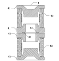
도 4, 즉 본 발명의 실시예 4에 의해 제공된 가스 방전관의 축 방향 단면도를 참조하도록 한다. 도 4에서 나타낸 바와 같이, 본 실시예의 가스 방전관(4)은 전극(41), 절연관체(42), 저온 밀봉 접합물(43)을 포함한다.4, that is, an axial sectional view of the gas discharge tube provided by the fourth embodiment of the present invention. 4, the
구체적으로, 본 실시예에 따른 가스 방전관(4)은 3극관으로서, 상단 전극, 하단 전극 및 중간 전극을 포함한다.Specifically, the
상기 가스 방전관(4)의 중간 전극(41)에는 상기 중간 전극(41)이 두 부분으로 분리되도록 분리층이 마련되며, 상기 저온 밀봉 접합물(43)은 상기 분리층에 설치되어 두 부분으로 분리된 상기 중간 전극(41)을 밀봉 연결시킨다.The
본 실시예는 아래와 같은 장점을 갖는다:The present embodiment has the following advantages:
가스 방전관의 중간 전극에는 저온 밀봉 접합물로 밀봉된 분리층이 설치된다. 따라서, 벼락으로 인한 과전압을 받을 경우, 해당 가스 방전관은 과전압 보호의 성능을 발휘할 수 있을 뿐만 아니라; 또한 해당 가스 방전관에 대전류가 흐르거나 과전류가 장시간 흘러 특정 온도까지 승온할 경우, 상기 저온 밀봉 접합물은 용점에 도달하여 용융되기 시작하며 상기 분리층에는 가스 누설이 발생하여 외부 공기가 상기 가스 방전관의 방전 내부챔버로 유입되며, 따라서 회로가 신속히 차단되어 회로의 안전을 보호할 수 있다.The intermediate electrode of the gas discharge tube is provided with a separation layer sealed with a low-temperature sealing joint. Therefore, when an overvoltage due to a lightning strike is received, the gas discharge tube can not only exhibit the overvoltage protection performance; In addition, when a large current flows in the gas discharge tube or an overcurrent flows for a long time to raise the temperature to a specific temperature, the low temperature sealing joint reaches the melting point and starts to melt, and gas leakage occurs in the separation layer, It enters the discharge inner chamber, and thus the circuit is quickly shut down to protect the safety of the circuit.
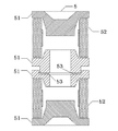
도 5, 즉 본 발명의 실시예 5에 의해 제공된 가스 방전관의 축 방향 단면도를 참조하도록 한다. 도 5에서 나타낸 바와 같이, 본 실시예의 가스 방전관(5)은 전극(51), 절연관체(52) 및 저온 밀봉 접합물(53)을 포함한다.5, that is, an axial cross-sectional view of the gas discharge tube provided by the
도 4에서 나타낸 실시예와의 차이점은 아래와 같다: 본 실시예에서의 중간 전극(51)의 분리층은 굴절 라인의 개구형이지만, 도 4에서 나타낸 실시예에서의 분리층은 직선 개구형이며, 이의 저온 밀봉 접합물(53)은 방전 내부챔버와 직선으로 연결되는 단면에 설치된다. 이외의 기타 부품은 모두 도 4에서 나타낸 실시예와 동일하므로 여기서 더 설명하지 않는다.4 is as follows: The separation layer of the
본 실시예는 아래와 같은 장점을 갖는다:The present embodiment has the following advantages:
가스 방전관의 중간 전극에는 굴절 라인 개구형의 분리층이 설치되고, 저온 밀봉 접합물로는 이와 방전 내부챔버가 직선 연결되는 포트를 밀봉한다. 따라서, 제품 리플로우 납땜(reflow soldering)을 진행할 경우, 저온 밀봉 접합물은 마운팅 외부 전극(surface-mounted outer electrode)의 솔더층(Solder layer)과 직접 접촉하지 않으며, 또한 개구는 방열의 효과를 가지므로, 리플로우 납땜을 진행하는 경우 저온 밀봉 접합물이 과열로 파손되어 가스 누설이 발생하는 현상을 방지할 수 있다. 그리고, 벼락으로 인한 과전압을 받을 경우, 해당 가스 방전관은 과전압 보호의 성능을 발휘할 수 있을 뿐만 아니라; 또한 해당 가스 방전관에 대전류가 흐르거나 과전류가 장시간 흘러 특정 온도까지 승온할 경우, 상기 저온 밀봉 접합물은 용점에 도달하여 용융되기 시작하며 상기 분리층에는 가스 누설이 발생하여 외부 공기가 상기 가스 방전관의 방전 내부챔버로 유입되며, 따라서 회로가 신속히 차단되어 회로의 안전을 보호할 수 있다.An intermediate layer of the gas discharge tube is provided with a separation layer of a refractive index opening type, and the low temperature sealing joint seals a port in which the discharge inner chamber is linearly connected. Therefore, when reflow soldering the product, the low-temperature sealing joint does not directly contact the solder layer of the surface-mounted outer electrode, and the opening has the effect of heat dissipation Therefore, when reflow soldering is performed, it is possible to prevent the occurrence of gas leakage due to breakage of the low-temperature seal joint due to overheating. In addition, when the overvoltage due to the lightning strikes, the gas discharge tube can not only exhibit the overvoltage protection performance; In addition, when a large current flows in the gas discharge tube or an overcurrent flows for a long time to raise the temperature to a specific temperature, the low temperature sealing joint reaches the melting point and starts to melt, and gas leakage occurs in the separation layer, It enters the discharge inner chamber, and thus the circuit is quickly shut down to protect the safety of the circuit.
도 6, 즉 본 발명의 실시예 6에 의해 제공된 가스 방전관의 축 방향 단면도를 참조하도록 한다. 도 6에서 나타낸 바와 같이, 본 실시예의 가스 방전관(6)은 전극(61), 절연관체(62) 및 저온 밀봉 접합물(63)을 포함한다.6, that is, an axial sectional view of the gas discharge tube provided by the
도 5에서 나타낸 실시예와의 차이점은 아래와 같다: 본 실시예에서의 저온 밀봉 접합물(63)은 가스 방전관 외부와 직선 연결되는 단면에 설치된다. 이외의 기타 부품은 모두 도 5에서 나타낸 실시예와 동일하므로 여기서 더 설명하지 않는다.The difference from the embodiment shown in Fig. 5 is as follows: The low-temperature sealing joint 63 in this embodiment is installed in a cross section that is linearly connected to the outside of the gas discharge tube. All other components are the same as the embodiment shown in Fig. 5 and will not be described further here.
본 실시예는 아래와 같은 장점을 갖는다:The present embodiment has the following advantages:
가스 방전관의 중간 전극에는 굴절 라인형의 분리층이 설치되고, 저온 밀봉 접합물로는 이와 가스 방전관 외부가 진선 연결되는 포트를 밀봉하므로, 그 밀봉 효과가 좋고, 상기 저온 밀봉 접합물은 흡열이 비교적 늦어 쉽게 용융되지 않으므로 비교적 늦은 용융 속도 요구인 상황에 적합하다. 벼락으로 인한 과전압을 받을 경우, 해당 가스 방전관은 과전압 보호의 성능을 발휘할 수 있을 뿐만 아니라; 또한 해당 가스 방전관에 대전류가 흐르거나 과전류가 장시간 흘러 특정 온도까지 승온할 경우, 상기 저온 밀봉 접합물은 용점에 도달하여 용융되기 시작하며 상기 분리층에는 가스 누설이 발생하여 외부 공기가 상기 가스 방전관의 방전 내부챔버로 유입되며, 따라서 회로가 신속히 차단되어 회로의 안전을 보호할 수 있다.Since the low-temperature sealing joint seals the port where the gas discharge tube is internally connected to the outside of the gas discharge tube, the sealing effect is good, and the low temperature sealing joint has a relatively low heat absorption It is suitable for situations requiring relatively low melt rates since they are not easily melted late. In case of overvoltage due to a lightning bolt, the gas discharge tube not only can exhibit the overvoltage protection performance; In addition, when a large current flows in the gas discharge tube or an overcurrent flows for a long time to raise the temperature to a specific temperature, the low temperature sealing joint reaches the melting point and starts to melt, and gas leakage occurs in the separation layer, It enters the discharge inner chamber, and thus the circuit is quickly shut down to protect the safety of the circuit.
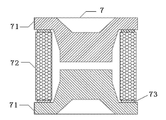
도 7, 즉 본 발명의 실시예 7에 의해 제공된 가스 방전관의 축 방향 단면도를 참조하도록 한다. 도 7에서 나타낸 바와 같이, 본 실시예의 가스 방전관(7)은 전극(71), 절연관체(72) 및 저온 밀봉 접합물(73)을 포함한다.7, that is, the axial sectional view of the gas discharge tube provided by the seventh embodiment of the present invention. 7, the
구체적으로, 상기 절연관체(72)는 상하 두 개의 포트가 마련되는데, 각각 제 1 포트 및 제 2 포트라 한다. 상기 절연관체(72)의 제 1 포트와 상기 전극(71) 사이는 저온 밀봉 접합물(73)에 의해 밀봉된다.Specifically, the
일 바람직한 실시예에서, 상기 절연관체(72)의 제 1 포트는 금속화층이고 상기 저온 밀봉 접합물(73)은 저온 솔더이다. 바람직하게, 상기 금속화층은 몰리브덴-망간 층(molybdenum-manganese layer)이고 1 층 또는 복수 층일 수 있다. 바람직하게, 상기 저온 솔더는 저온 주석 솔더(tin solder)이다.In one preferred embodiment, the first port of the
다른 바람직한 실시예에서, 상기 절연관체(72)의 제 1 포트는 백자기(ceramic whiteware)이고 상기 저온 밀봉 접합물(73)은 저온 접착제이다. 바람직하게, 상기 저온 접착제(73)는 글루 등 유기 접착제이다.In another preferred embodiment, the first port of the
일 바람직한 실시예에서, 상기 절연관체(72)의 제 2 포트와 상기 전극(71) 사이는 저온 밀봉 접합물(73)에 의해 밀봉된다.In one preferred embodiment, a gap between the second port of the insulated
구체적으로, 상기 제 2 포트는 금속화층 또는 백자기이고, 제 2 포트가 금속화층인 경우, 상기 저온 밀봉 접합물은 저온 솔더이고; 제 2 포트가 백자기인 경우, 상기 저온 밀봉 접합물은 저온 접착제이다.Specifically, when the second port is a metallization layer or white magnet and the second port is a metallization layer, the low temperature seal joint is a low temperature solder; When the second port is a white porcelain, the low temperature sealing joint is a low temperature adhesive.
일 바람직한 실시예에서, 상기 절연관체(72)와 상기 전극(71)의 접착 면적은 상기 저온 밀봉 접합물(73)이 특정 용융 요구를 충족시키도록 설정된다. 구체적으로, 상기 특정 용융 요구는, 실제 회로에서 회로 사용 환경 및 보호해야 하는 소자의 내고온 성능에 따라 상기 저온 밀봉 접합물(73)의 용융 속도가 설정되는 것이다. 예를 들어, 회로의 정상적인 작동 온도가 0∼350℃이고 보호해야 하는 임의의 전자 부품의 최고 내고온 온도가 370℃이고 30s 지속할 수 있을 경우, 상기 저온 밀봉 접합물(73)이 충족해야 하는 특정 용융 요구는, 0∼350℃에서 용융되지 않고 350℃∼370℃ 구간 내에서 용융이 시작되며 370℃에 도달하면 25s 내에 반드시 용융되어야 하는 것이다. 이로써 상기 가스 방전관은 가스 누설되어 단로되므로 해당 전기부품을 보호할 수 있다.In one preferred embodiment, the area of adhesion of the
바람직하게, 상기 절연관체(72)와 상기 전극(71)의 접착 면적의 설정에는 아래의 4 가지 방법을 포함한다:Preferably, the setting of the area of adhesion between the insulating
방법 1: 상기 절연관체(72)의 직경폭을 상기 절연관체(72)와 저온 밀봉 접합물(73)의 접촉면적이 특정 면적이 되도록 특정 너비로 설치하여 상기 저온 밀봉 접합물(13)의 용융 속도를 편리하게 제어한다. Method 1: The diameter of the
방법 2: 상기 절연관체(72)에서 저온 밀봉 접합물(73)에 의해 밀봉되는 포트에 특정 너비의 돌기를 설치하고, 해당 돌기와 상기 저온 밀봉 접합물(73)을 접착시켜 상기 저온 밀봉 접합물(73)의 용융 속도를 편리하게 제어한다.Method 2: A protrusion having a specific width is provided on a port sealed by the low temperature sealing joint 73 in the
방법 3: 상기 저온 밀봉 접합물(73)을 특정 너비로 설치하여 상기 저온 밀봉 접합물(73)의 용융속도를 편리하게 제어한다. Method 3: The low temperature sealing joint 73 is installed at a specific width to conveniently control the melting rate of the low temperature sealing joint 73.
방법 4: 상기 저온 밀봉 접합물(73)과 접촉하는 상기 전극(71)의 내표면에 특정 너비의 돌기를 설치하고, 해당 돌기와 상기 저온 밀봉 접합물(73)을 접착시켜 상기 저온 밀봉 접합물(73)의 용융속도를 편리하게 제어한다.Method 4: A projection having a specific width is provided on the inner surface of the
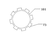
바람직하게, 상기 전극(71), 및/또는 상기 저온 밀봉 접합물(73), 및/또는 상기 절연관체(72)의 포트에 리키네스 포인트(leakiness point)가 설치되되, 상기 절연관체(72)와 상기 전극(71)의 상기 리키네스 포인트 위치에서의 접착면적이 다른 위치에서의 접착면적보다 작게 설치되며, 상기 리키네스 포인트가 하나 또는 복수 개 설치된다. 구체적으로, 도 10, 즉 본 실시예에 의해 제공된 가스 방전관의 저온 밀봉 접합물(73)의 횡단면도를 참조 결합하면, 도면에는 복수 개의 리키네스 포인트(101)가 설치된다.Preferably, a leakiness point is provided at a port of the
구체적으로, 상기 리키네스 포인트(101)는 상기 저온 밀봉 접합물(73)의 부착력이 가장 약하고 재료가 가장 적은 등 원인으로 하여 용융되기 쉬운 위치이며, 이가 용융됨으로써 상기 가스 방전관을 가스 누설시켜 회로를 차단시킨다.Specifically, the recycling point (101) is a position where the low temperature sealing joint (73) is most likely to be melted due to the weakest adhesive force and the least amount of material. The gas leakage tube .
본 실시예는 아래와 같은 장점을 갖는다:The present embodiment has the following advantages:
본 실시예의 가스 방전관은 절연관체의 포트에 저온 밀봉 접합물을 사용하여 이를 밀봉한다. 따라서 벼락으로 인한 과전압을 받을 경우, 해당 가스 방전관은 과전압 보호의 성능을 발휘할 수 있을 뿐만 아니라; 또한 해당 가스 방전관에 대전류가 흐르거나 과전류가 장시간 흘러 특정 온도까지 승온할 경우, 상기 저온 밀봉 접합물은 용점에 도달하여 용융되기 시작하며 방전 내부챔버는 가스 누설이 발생하여 외부 공기가 상기 가스 방전관의 방전 내부챔버로 유입되며, 따라서 회로가 신속히 차단되어 회로의 안전을 보호할 수 있다.The gas discharge tube of this embodiment uses a low temperature sealing joint to seal the port of the insulated tubular body. Therefore, in case of overvoltage due to a lightning strike, the gas discharge tube not only can exhibit the overvoltage protection performance; In addition, when a large current flows in the gas discharge tube or an overcurrent flows for a long time to raise the temperature to a specific temperature, the low temperature sealing joint reaches the melting point and starts to melt, and the gas leakage occurs in the discharge inner chamber, It enters the discharge inner chamber, and thus the circuit is quickly shut down to protect the safety of the circuit.
더 나아가, 본 발명은 실시예 7의 바람직한 방안으로서 아래의 두 가지 바람직한 방안을 제공한다:Further, the present invention provides the following two preferred methods as a preferred method of Embodiment 7:
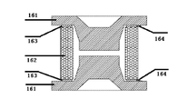
도 16, 즉 본 발명의 실시예 7에 의해 제공된 제 1 바람직한 방안의 가스 방전관의 축 방향 단면도를 참조하면, 전극(161) 및 절연관체(162)를 포함하고 상기 전극(161)과 상기 절연관체(162) 사이는 저온 밀봉 접합물(163)로 밀봉되는 점에서 도 7에서 나타낸 실시예와 동일하나; 양자의 차이점은 해당 가스 방전관 일측의 상기 저온 밀봉 접합물(163)의 외부 표면에는 열전도율이 상기 전극의 열전도율보다 작은 보호층(164)이 설치되는 것이다. 구체적으로, 상기 보호층은 니켈층, 크롬층, 기타 금속층 또는 비금속층이고, 상기 저온 밀봉 접찹물(163)의 외부 표면에 전기 도금 또는 분말 코팅(Powder coating)의 방식을 채용하여 설치된다. 그 이점은 아래와 같다: 1. 상기 가스 방전관이 사용자에 의해 마운팅 리플로우 납땜될 때, 상기 보호층의 열전도율이 낮아 외부 열량이 비교적 적게 상기 저온 밀봉 접합물(163)에 전도되므로, 상기 가스 방전관이 리플로우 납땜될 때, 오작동으로 인해 개로되어 실효되는 것을 방지할 수 있다; 2. 상기 가스 방전관에 대전류가 흐르거나 과전류가 장시간 흘러 발열할 경우, 상기 보호층의 열전도율이 낮아 가스 방전관 내부의 열량이 비교적 적게 외부로 유실되므로, 상기 열량은 보다 더 집중적으로 상기 저온 밀봉 접합물의 용융에 사용될 수 있어 상기 가스 방전관을 신속히 개로시킬 수 있다.16, that is, the axial sectional view of the gas discharge tube of the first preferred embodiment provided by the seventh embodiment of the present invention, the
도 17, 즉 본 발명의 실시예 7에 의해 제공된 제 2 바람직한 방안의 가스 방전관의 축 방향 단면도를 참조하도록 한다.17, that is, the axial sectional view of the gas discharge tube of the second preferred embodiment provided by the seventh embodiment of the present invention.
이와 도 16에서 나타낸 실시예의 차이점은, 해당 가스 방전관의 절연관체 이외의 모든 외부 표면에는 모두 보호층(174)이 마련되고, 즉 상기 전극과 상기 저온 밀봉 접합물의 외부 표면에는 모두 보호층(174)이 마련되는바, 상기 보호층(174)의 열전도율은 열전도가 상대적으로 늦게 되도록 상기 전극의 열전도율보다 작다. 구체적으로, 상기 보호층은 니켈층, 크롬층, 기타 금속층 또는 비금속층이고, 상기 전극 및 상기 저온 밀봉 접찹물의 외부 표면에 전기 도금 또는 분말 코팅의 방식을 채용하여 설치된다. 그 이점은 아래와 같다: 1. 상기 가스 방전관이 사용자에 의해 마운팅 리플로우 납땜될 때, 상기 보호층의 열전도율이 낮고, 또한 보호층은 열전도율이 비교적 큰 전극을 커버하여 외부 열량이 상기 저온 밀봉 접합물에 전도되는 것을 더 한층 차단할 수 있으므로, 상기 가스 방전관이 리플로우 납땜될 때 오작동으로 인해 개로되어 실효되는 것을 방지할 수 있다; 2. 상기 가스 방전관에 대전류가 흐르거나 과전류가 장시간 흘러 발열할 경우, 상기 보호층의 열전도율이 낮고 보호층이 열전도율이 비교적 큰 전극을 커버하여 가스 방전관 내부의 열량이 보다 더 적게 외부로 유실될 수 있으므로, 상기 열량은 보다 더 집중적으로 상기 저온 밀봉 접합물의 용융에 사용될 수 있어 상기 가스 방전관을 신속히 개로시킬 수 있다.16 differs from the embodiment shown in FIG. 16 in that a
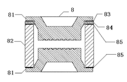
도 8, 즉 본 발명의 실시예 8에 의해 제공된 가스 방전관의 축 방향 단면도를 참조하도록 한다. 도 8에서 나타낸 바와 같이, 본 실시예의 가스 방전관(8)은 전극(81), 절연관체(82), 저온 밀봉 접합물(85), 금속링(84) 및 고온 솔더층(high temperature solder layer)(85)을 포함한다. 상기 절연관체(82)에는 상, 하 두 개의 포트가 마련되며 각각 두 개의 전극(81)이 밀봉 연결된다. 구체적으로, 절연관체(82)의 상부 포트에는 고온 솔더층(85)을 통해 금속링(84)이 밀봉 연결되며, 금속링(84)은 저온 밀봉 접합물(83)을 통해 전극(81)에 밀봉 연결되며; 절연관체(82)의 하부 포트는 고온 솔더층(85)을 통해 전극(81)에 밀봉 연결된다.8, that is, an axial sectional view of the gas discharge tube provided by the eighth embodiment of the present invention. 8, the
구체적으로, 상기 금속링(84)은 상기 절연관체(82)와의 고온 밀봉에 적합할뿐만 아니라, 상기 전극(81)과의 저온 밀봉에도 적합하다. 하나의 바람직한 실시예에서, 상기 금속링(84)은 무산소구리(oxygen-free copper) 링이다. 다른 하나의 바람직한 실시예에서, 상기 저온 밀봉 접합물(83)과 접촉되는 상기 금속링(84)의 표면은 거친면이고, 거친면은 부착력이 강해 상기 금속링(84)이 상기 저온 밀봉 접합물(83)에 보다 더 견고하게 밀봉 접착될 수 있도록 한다. 다른 하나의 바람직한 실시예에서, 상기 금속링(84)의 단면 링의 너비는 상기 절연관체(82)의 단면 너비보다 크므로, 상기 금속링(84)과 상기 저온 밀봉 접합물(83)의 접촉면적을 증가할 수 있으며, 즉 양자의 접착면적이 증가할 수 있으므로, 상기 금속링(84)은 상기 저온 밀봉 접합물(83)에 보다 더 견고하게 밀봉 접착될 수 있다.Specifically, the
바람직하게, 상기 절연관체(82)의 상부 포트에는 금속화층(미도시)이 마련되고, 바람직하게는 몰리브덴-망간 층이 마련되며; 상기 금속링(84)은 고온 솔더를 통해, 바람직하게는 은동 솔더를 통해, 상기 절연관체(82)의 금속화층에 밀봉 연결된다.Preferably, a metallization layer (not shown) is provided on the upper port of the
본 실시예는 아래와 같은 장점을 갖는다:The present embodiment has the following advantages:
본 실시예의 가스 방전관에 있어서, 절연관체의 일 포트에는 금속링이 설치되고, 해당 포트에서 저온 밀봉 접합물을 사용하여 이를 밀봉한다. 따라서, 벼락으로 인한 과전압을 받을 경우, 해당 가스 방전관은 과전압 보호의 성능을 발휘할 수 있을 뿐만 아니라; 또한 해당 가스 방전관에 대전류가 흐르거나 과전류가 장시간 흘러 특정 온도까지 승온할 경우, 상기 저온 밀봉 접합물은 용점에 도달하여 용융되기 시작하며 방전 내부챔버는 가스 누설이 발생하여 외부 공기가 상기 가스 방전관의 방전 내부챔버로 유입되며, 따라서 회로가 신속히 차단되어 회로의 안전을 보호할 수 있다.In the gas discharge tube of this embodiment, a metal ring is provided at one port of the insulated tubular body, and a low-temperature sealing joint is used at the port to seal it. Therefore, when an overvoltage due to a lightning strike is received, the gas discharge tube can not only exhibit the overvoltage protection performance; In addition, when a large current flows in the gas discharge tube or an overcurrent flows for a long time to raise the temperature to a specific temperature, the low temperature sealing joint reaches the melting point and starts to melt, and the gas leakage occurs in the discharge inner chamber, It enters the discharge inner chamber, and thus the circuit is quickly shut down to protect the safety of the circuit.
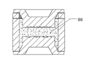
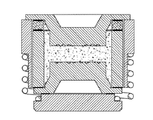
본 실시예는 다른 5 가지의 바람직한 방안을 더 포함하며, 도 11은 제 1 바람직한 방안의 가스 방전관의 축 방향 단면도이며, 도 11의 도시를 참조하도록 한다. 도 11에서 나타낸 가스 방전관은 전극, 절연관체, 저온 밀봉 접합물, 금속링 및 고온 솔더층을 포함한다는 점에서 도 8에서 나타낸 가스 방전관과 동일하고; 도 8에서 나타낸 가스 방전관과의 차이점은, 도 11에서 나타낸 가스 방전관은 방전 내부챔버에 절연 입자상 물질(particulate matter)(86)이 충진되는 것이다. 바람직하게, 상기 절연 입자상 물질은 규사(quartz sand) 입자이다. 본 방안의 장점은 아래와 같다: 방전 내부챔버에 절연 입자상 물질이 충진되면, 방전 내부챔버가 방전 시 생성되는 열량은 절연 입자상 물질에 의해 대량으로 흡수되므로, 상기 가스 방전관에 대전류가 흐를 경우, 상기 방전 내부챔버 양단의 전극이 너무 빨리 승온하고 용융되어 폭발하고 날리는 정도까지는 이르지 않아, 상기 저온 밀봉 접합물의 용융되어 가스 누설되는데 까지의 시간을 쟁취할 수 있어, 회로에 대한 개로 보호 효과가 더 한층 증가된다. 이와 반대로, 규사를 첨가하지 않으면, 상기 가스 방전관에 대전류가 흐르는 경우 순간 방전열량이 지나치게 커지게 되는데, 이로 인해 상기 저온 밀봉 접합물이 용융되어 가스 누설을 일으키기도 전에, 상기 전극이 용융되어 폭발하고 날리어 단락을 초래할 수 있다.This embodiment further comprises five other preferred embodiments, and Fig. 11 is an axial cross-sectional view of the gas discharge tube of the first preferred embodiment, with reference to the view of Fig. The gas discharge tube shown in Fig. 11 is the same as the gas discharge tube shown in Fig. 8 in that it includes an electrode, an insulating tube, a low-temperature sealing joint, a metal ring and a high-temperature solder layer; The difference from the gas discharge tube shown in Fig. 8 is that the gas discharge tube shown in Fig. 11 is filled with the insulating
도 12는 제 2 바람직한 방안의 가스 방전관의 축 방향 단면도이며, 도 12의 도시를 참조하도록 한다. 도 12에서 나타낸 가스 방전관은 전극, 절연관체, 저온 밀봉 접합물, 금속링 및 고온 솔더층을 포함하는 점에서 도 8에서 나타낸 가스 방전관과 동일하고; 도 8에서 나타낸 가스 방전관과의 차이점은, 도 12에서 나타낸 가스 방전관은 하나의 자유단(871)을 구비하는 스프링 장치(87)를 더 포함하는 것이다. 상기 자유단(871)은 상기 저온 밀봉 접합물과 접착된 전극에 의해 수축된 상태로 가압되고, 상기 저온 밀봉 접합물이 용융될 경우, 해당 자유단(871)이 상기 전극에 대한 반작용력이 상기 전극과 상기 저온 밀봉 접합물 사이의 접착력보다 커져 해당 자유단(871)은 신장되어 상기 저온 밀봉 접합물과 접착된 전극을 밀어낸다. 마찬가지로, 상기 가스 방전관 양단이 모두 저온 밀봉 접합물이 설치되는 경우, 상기 스프링 장치에는 2 개의 자유단(미도시)이 설치될 수 있으며, 어느 하나의 자유단의 저온 밀봉 접합물이 용융되기만 하면 해당 자유단은 신장되어 해당 단부의 전극을 밀어낸다. 그 장점은 아래와 같다: 상기 가스 방전관에 대전류가 흐르는 경우, 상기 저온 밀봉 접합물이 용융되기 시작하여 이와 전극 사이의 접착력이 작아질 때까지 용융되면, 힘의 균형이 깨져 해당 스프링 장치는 자유단이 신장되고, 상기 저온 밀봉 접합물과 접착된 전극을 신속히 밀어내 급속으로 가스가 누설되어 개로되도록 하며, 이로써 회로에 대한 개로 보호 효과를 더 한층 제고한다. 이와 반대로, 스프링 장치를 설치하지 않으면, 상기 가스 방전관에 대전류가 흐르는 경우, 순간 방전열량이 지나치게 커지게 되는데, 이로 인해 상기 저온 밀봉 접합물이 용융되어 가스 누설을 일으키기도 전에, 상기 전극이 이미 용융되어 폭발하고 날리어 단락을 초래할 수 있다.Fig. 12 is an axial cross-sectional view of the gas discharge tube of the second preferred embodiment, and reference is made to Fig. 12. The gas discharge tube shown in Fig. 12 is the same as the gas discharge tube shown in Fig. 8 in that it includes an electrode, an insulating tube, a low-temperature sealing joint, a metal ring and a high-temperature solder layer; The difference from the gas discharge tube shown in FIG. 8 is that the gas discharge tube shown in FIG. 12 further includes a spring device 87 having one free end 871. The free end (871) is pressed in a contracted state by the electrode bonded to the low temperature sealing joint, and when the low temperature sealing joint is melted, the free end (871) Is greater than the adhesive force between the electrode and the low-temperature sealing joint, and the free end 871 is stretched to push out the electrode adhered to the low-temperature sealing joint. Similarly, if both ends of the gas discharge tube are provided with low-temperature sealing joints, the spring device may be provided with two free ends (not shown). If the low- temperature sealing joints of either free end are melted, The free end extends and pushes out the electrode at the end. The advantages are as follows: When a large current flows through the gas discharge tube, when the low-temperature sealing joint starts to melt and melts until the adhesion between the electrodes becomes small, the balance of the force is broken, And the electrode adhered to the low-temperature sealing joint is rapidly pushed out so that the gas leaks out rapidly, thereby further enhancing the open protection effect on the circuit. On the other hand, if a large current flows through the gas discharge tube without providing a spring device, the amount of instantaneous discharge heat becomes excessively large. As a result, before the low temperature sealing joint melts to cause gas leakage, It can explode and fly and short circuit.
도 13은 제 3 바람직한 방안의 가스 방전관의 축 방향 단면도이며 도 13의 도시를 참조하도록 한다. 도 13에서 나타낸 가스 방전관은 도 11과 도 12에서 나타낸 가스 방전관의 장점을 종합, 즉 상기 가스 방전관에는 스프링 장치가 설치될뿐만 아니라 상기 방전 내부챔버에 절연 입자상 물질이 충진되어, 상기 가스 방전관에 대전류가 흐르는 경우 곧바로 개로되도록 더 한층 확보하므로 회로에 대하여 이중 보호를 실현할 수 있다. Fig. 13 is an axial sectional view of the gas discharge tube of the third preferred embodiment, and reference is made to Fig. 13. The gas discharge tube shown in Fig. 13 has the advantages of the gas discharge tube shown in Figs. 11 and 12, that is, a spring device is installed in the gas discharge tube, the insulated particulate matter is filled in the discharge inner chamber, So that double protection can be realized for the circuit.
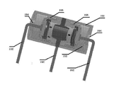
도 14는 본 발명의 실시예 8에 의해 제공된 제 4 바람직한 방안의 가스 방전관의 축 방향 단면도이며 도 14의 도시를 참조하도록 한다. 도 14에서 나타낸 가스 방전관은 스프링 장치(145), 전극(146), 절연관체(147), 저온 밀봉 접합물(148), 금속링(149) 및 고온 솔더층(140)을 구비하는 점에서 도 12에서 나타낸 가스 방전관과 동일하고; 도 12에서 나타낸 가스 방전관과의 차이점은 아래와 같다: 도 14에서 나타낸 가스 방전관은, 두 개의 상기 전극과 각각 연결되는 핀(pin)(142) 및 상기 스프링 장치(145)를 수용하는 캐비티(cavity)(143)를 구비하는 하우징(141)을 더 포함하며, 상기 캐비티(143)에는 외부 공기와 서로 연통되는 관통홀(144)이 더 마련되며, 하나의 상기 핀(142)은 상기 관통홀(144)에서 부터 연장되어 나온다. 바람직하게, 상기 하우징은 세라믹 하우징이다. 그 장점은 아래와 같다: 상기 가스 방전관에 대전류가 흐르는 경우, 상기 저온 밀봉 접합물이 용융되기 시작하여 이와 전극 사이의 접착력이 작아질 때까지 용융되면, 해당 스프링 장치는 힘의 균형이 깨져 자유단이 신장되고 상기 저온 밀봉 접합물과 접착된 전극을 신속히 밀어내 급속으로 가스 누설되어 개로되도록 하며, 아울러, 하우징이 설치됨으로써 해당 가스 방전관이 개로시 분산되어 떨어질 수 있는 부품이 지면에 떨어지지 않게 할 수 있다.Fig. 14 is an axial cross-sectional view of the gas discharge tube of the fourth preferred embodiment provided by the eighth embodiment of the present invention, and reference is made to Fig. 14. The gas discharge tube shown in Fig. 14 also has a
도 15는 본 발명의 실시예 8에 의해 제공된 제 5 바람직한 방안의 가스 방전관의 축 방향 단면도이며 도 15의 도시를 참조하도록 한다. 도 15에서 나타낸 가스 방전관과 도 14에서 나타낸 제 4 바람직한 방안의 가스 방전관과의 차이점은 아래와 같다: 해당 가스 방전관은 3극관이고; 두 개의 스프링 장치(155), 3 개의 상기 전극에 각각 연결되는 핀(152), 및 상기 스프링 장치(155)를 수용하는 캐비티(153)를 구비하는 하우징(151)이 마련되며; 상기 캐비티(153)에는 두 개의 외부 공기와 서로 연통되는 관통홀(154)이 더 마련되며, 두 개의 상기 핀(152)은 상기 관통홀(154)에서 부터 연장되어 나온다. 그 장점은 도 14에서 나타낸 바람직한 방안과 동일하므로 여기서 더 설명하지 않는다.Fig. 15 is an axial cross-sectional view of the gas discharge tube of the fifth preferred embodiment provided by the eighth embodiment of the present invention, and is referred to the view of Fig. The difference between the gas discharge tube shown in Fig. 15 and the gas discharge tube of the fourth preferred embodiment shown in Fig. 14 is as follows: the gas discharge tube is a triode tube; A
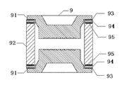
도 9, 즉 본 발명의 실시예 9에 의해 제공된 가스 방전관의 축 방향 단면도를 참조하면, 상기 가스 방전관(9)은 절연관체(92), 전극(91), 금속링(94), 저온 밀봉 접합물(93) 및 고온 솔더층(95)을 포함한다. 상기 절연관체(92)는 상하 두 개의 포트를 구비하고, 각각 고온 솔더층(95)을 통해 금속링(94)에 밀봉 연결되며, 금속링(94)은 저온 밀봉 접합물(93)을 통해 전극(91)에 밀봉 연결된다.9, that is, the axial sectional view of the gas discharge tube provided by the ninth embodiment of the present invention, the
주의해야 할 것은, 본 실시예에서 "절연관체(92)의 하부 포트에도 금속링(94)이 설치되고 절연관체의 하부 포트는 고온 솔더층(95)을 통해 금속링(94)에 밀봉 연결되며, 금속링(94)은 저온 밀봉 접합물(93)을 통해 전극(91)에 밀봉 연결되는" 것 외에, 나머지 부분의 특징은 전부 도 8에서 나타낸 실시예와 동일하므로, 구체적으로 도 8에서 나타낸 실시예를 참조하면 되므로, 여기서 더 설명하지 않는다. 절연관체(92)의 두 개의 포트는 모두 금속링 및 저온 밀봉 접합물이 설치되어, 해당 가스 방전관이 과전류로 인한 발열로 하여 승온할 때, 보다 더 용이하게 가스 누설이 발생하여 회로가 차단되며, 이로써 회로의 안전을 더 한층 확보할 수 있다.It should be noted that in this embodiment, a
본 실시예는 아래와 같은 장점을 갖는다:The present embodiment has the following advantages:
본 실시예의 가스 방전관은 절연관체의 두 개의 포트에 금속링이 설치되고, 상기 포트에 저온 밀봉 접합물을 사용하여 이를 밀봉한다. 따라서, 벼락으로 인한 과전압을 받을 경우, 해당 가스 방전관은 과전압 보호의 성능을 발휘할 수 있을 뿐만 아니라; 또한 해당 가스 방전관에 대전류가 흐르거나 과전류가 장시간 흘러 특정 온도까지 승온할 경우, 어느 하나의 상기 저온 밀봉 접합물은 용점에 도달하여 용융되기 시작하며 방전 내부챔버는 가스 누설이 발생하여 외부 공기가 상기 가스 방전관의 방전 내부챔버로 유입되며, 따라서 회로가 신속히 차단되어 회로의 안전을 보호할 수 있다.The gas discharge tube of this embodiment is provided with a metal ring at two ports of an insulated tubular body, and the port is sealed with a low-temperature sealing joint. Therefore, when an overvoltage due to a lightning strike is received, the gas discharge tube can not only exhibit the overvoltage protection performance; When a large current flows in the gas discharge tube or an overcurrent flows for a long time to raise the temperature to a certain temperature, any one of the low temperature sealing joints reaches the melting point and starts to melt, and the gas leakage occurs in the discharge inner chamber, The gas is introduced into the discharge inner chamber of the gas discharge tube, so that the circuit can be quickly shut off to protect the safety of the circuit.
분명한 것은 상기 실시예는 단지 명확히 설명하기 위한 예일 뿐, 실시형태에 대한 한정이 아니다. 상기 어느 하나의 실시예에서의 임의의 기술특징도 기타 실시예에 이요 가능하며, 예를 들어, 절연관체와 전극의 접착면적의 설정, 리키네스 포인트(쉽게 누설 가능한 포인트를 의미함)의 설치, 방전 내부챔버 중 절연 입자상 물질의 설치 및 스프링 장치의 설치는 모두 기타 실시예에 응용 가능하다. 본 분야 통상의 기술자에 있어서, 상술한 설명에 기반하여 다른 부동한 형태의 변화 또는 변동을 진행할 수 있다. 여기에서는 모든 실시형태를 예로 들지 않으며, 또한 그럴 필요도 없다. 저온 밀봉 접합물을 사용하여 방전 내부챔버를 밀봉하고 상기 저온 밀봉 접합물이 특정된 저온 용점에서 용융될 때 상기 방전 내부챔버가 가스 누설될 수 있는 가스 방전관이기만 하면, 해당 저온 밀봉 접합물이 어떠한 방식으로 해당 가스 방전관의 어디에 위치하든지를 막론하고 모두 본 출원의 청구범위 내에 속한다.Obviously, the above embodiment is merely an example for clarification, and is not limited to the embodiment. Any of the technical features in any of the above embodiments can be applied to other embodiments. For example, it is possible to set the adhesion area of the insulated tubular body and the electrode, the installation of the leakage point (meaning easily leakable point) The installation of the insulating particulate matter among the discharge inner chambers and the installation of the spring device are all applicable to other embodiments. In the ordinary course of the art, other types of changes or variations can be made based on the above description. It does not exemplify, nor need to, all embodiments. As long as the discharge inner chamber is sealed using the low-temperature sealing joint and the discharge inner chamber can be gas-leaked when the low-temperature sealing joint is melted at the specified low temperature point, Regardless of its position in the gas discharge tube, are all within the scope of the present application.
본 발명의 가스 방전관은 제조 및 사용이 가능하고, 해당 가스 방전관에 대전류가 흐르거나 과전류가 장시간 흘러 특정 온도까지 승온할 경우, 어느 하나의 상기 저온 밀봉 접합물은 용점에 도달하여 용융되기 시작하며 방전 내부챔버는 가스 누설이 발생하여 외부 공기가 상기 가스 방전관의 방전 내부챔버로 유입되며, 따라서 회로가 신속히 차단되어 회로의 안전을 보호할 수 있으므로 유익한 기술적 효과를 구비한다.The gas discharge tube of the present invention can be manufactured and used. When a large current flows in the gas discharge tube or an overcurrent flows for a long time and the temperature of the gas discharge tube increases to a specific temperature, any one of the low temperature sealing joints reaches a melting point, The inner chamber has a beneficial technical effect because gas leakage occurs and the outside air flows into the discharge inner chamber of the gas discharge tube and thus the circuit can be quickly shut off to protect the safety of the circuit.
Claims (15)
상기 가스 방전관에는 상기 방전 내부챔버를 밀봉하는 저온 밀봉 접합물이 마련되며, 상기 저온 밀봉 접합물은 특정된 저온에서 용융됨으로써 상기 방전 내부챔버가 가스 누설되도록 하는 것을 특징으로 하는 가스 방전관.A gas discharge tube comprising at least two electrodes and a leading tube sealingly connected to the electrode to form a discharge inner chamber,
Wherein the gas discharge tube is provided with a low-temperature sealing joint sealing the discharge inner chamber, wherein the low-temperature sealing joint is melted at a specified low temperature so that the discharge inner chamber is leaked.
적어도 하나의 상기 전극에는 축 방향 통기홀이 마련되고, 상기 통기홀의 내단부는 상기 방전 내부챔버에 연결되며 상기 통기홀의 외단부는 상기 저온 밀봉 접합물을 통해 커버 플레이트에 연결되는 것을 특징으로 하는 가스 방전관.The method according to claim 1,
Wherein at least one of the electrodes is provided with an axial vent hole and the inner end of the vent hole is connected to the discharge inner chamber and the outer end of the vent hole is connected to the cover plate through the low temperature sealing joint. .
적어도 하나의 상기 전극에는 반경방향 통기홀이 마련되고 상기 반경방향 통기홀의 적어도 하나의 포트는 상기 방전 내부챔버에 연결되며, 상기 반경방향 통기홀은 상기 전극 외부면의 요입홈을 통과하며, 상기 요입홈 상면에는 상기 요입홈을 커버하는 커버 플레이트가 마련되며 상기 커버 플레이트는 상기 저온 밀봉 접합물을 통해 상기 전극 외부면에 연결되는 것을 특징으로 하는 가스 방전관.The method according to claim 1,
Wherein at least one of said electrodes is provided with a radial vent hole and at least one port of said radial vent hole is connected to said discharge inner chamber, said radial vent hole passing through an entry groove of said electrode outer surface, Wherein the upper surface of the groove has a cover plate covering the concave groove and the cover plate is connected to the outer surface of the electrode through the low temperature sealing joint.
상기 절연관체에는 통기홀이 마련되고, 상기 통기홀의 외단부는 상기 저온 밀봉 접합물을 통해 커버 플레이트에 연결되는 것을 특징으로 하는 가스 방전관. The method according to claim 1,
Wherein the insulation tube is provided with a vent hole and an outer end of the vent hole is connected to the cover plate through the low temperature sealing joint.
상기 절연관체에는 상기 절연관체가 반경반향에서 두 부분으로 분리되도록 분리층이 마련되며, 상기 저온 밀봉 접합물은 상기 분리층에 설치되어 두 부분으로 분리된 두 개의 절연관체를 밀봉 연결시키는 것을 특징으로 하는 가스 방전관.The method according to claim 1,
Wherein the insulation tube is provided with a separation layer such that the insulation tube is divided into two parts in a radial direction, and the low temperature sealing joint is installed in the separation layer to seal and connect two insulation tubes, Gas discharge tube.
상기 가스 방전관의 중간 전극에는 상기 중간 전극이 두 부분으로 분리되도록 분리층이 마련되며, 상기 저온 밀봉 접합물은 상기 분리층에 설치되어 두 부분으로 분리된 상기 중간 전극을 밀봉 연결시키는 것을 특징으로 하는 가스 방전관. The method according to claim 1,
Wherein the intermediate electrode of the gas discharge tube is provided with a separation layer such that the intermediate electrode is divided into two parts, and the low temperature sealing joint is installed in the separation layer to seal the intermediate electrode separated into two parts Gas discharge tube.
적어도 하나의 상기 전극과 상기 절연관체 사이는 저온 밀봉 접합물을 사용하여 밀봉 연결시키는 것을 특징으로 하는 가스 방전관.The method according to claim 1,
Wherein at least one of the electrodes and the insulation tube are sealed by using a low-temperature sealing joint.
상기 적어도 하나의 상기 전극과 상기 절연관체 사이는 저온 밀봉 접합물을 사용하여 밀봉 연결시키는 것은,
상기 전극과 상기 절연관체 사이에는 금속화층 또는 금속링이 마련되어, 상기 전극과 상기 금속화층 또는 상기 금속링 사이는 저온 밀봉 접합물을 사용하여 밀봉 연결시키는 것을 포함하는 것을 특징으로 하는 가스 방전관.8. The method of claim 7,
Sealing the at least one electrode and the insulated tubular body using a low-temperature sealing joint,
Wherein a metallization layer or a metal ring is provided between the electrode and the insulator tube, and sealing between the electrode and the metalization layer or the metal ring using a low-temperature seal joint.
상기 가스 방전관은 적어도 하나의 자유단을 구비하는 스프링 장치를 더 포함하고, 상기 자유단은 상기 저온 밀봉 접합물과 접착된 전극에 의해 수축된 상태로 가압되고, 상기 저온 밀봉 접합물이 용융될 경우, 상기 자유단이 상기 전극에 대한 반작용력이 상기 전극과 상기 저온 밀봉 접합물 사이의 접착력보다 커져 상기 자유단은 신장되어 상기 저온 밀봉 접합물과 접착된 전극을 밀어내는 것을 특징으로 하는 가스 방전관.9. The method of claim 8,
The gas discharge tube further includes a spring device having at least one free end, the free end being pressed in a contracted state by an electrode bonded to the low temperature seal joint, and when the low temperature seal joint is melted Wherein the free end of the free end is greater than the adhesion force between the electrode and the low temperature sealing joint so that the free end is extended to push out the electrode adhered to the low temperature sealing joint.
상기 가스 방전관은 각 상기 전극과 각각 연결되는 핀 및 상기 스프링 장치를 수용하는 캐비티를 구비하는 하우징을 더 포함하며, 상기 캐비티는 외부 공기와 서로 연통되는 관통홀이 더 마련되며 적어도 하나의 상기 핀은 상기 관통홀에서 부터 연장되어 나오는 것을 특징으로 하는 가스 방전관.10. The method of claim 9,
Wherein the gas discharge tube further comprises a housing having a pin connected to each of the electrodes and a cavity for receiving the spring device, wherein the cavity further comprises a through hole communicating with outside air, And extends from the through-hole.
상기 저온 밀봉 접합물은 특정 형태로 설치됨으로써 상기 저온 밀봉 접합물이 특정 용융 요구를 충족시키는 것을 특징으로 하는 가스 방전관.10. The method according to any one of claims 1 to 9,
Wherein the low temperature seal joint is installed in a specific form so that the low temperature seal joint meets a specific melting requirement.
상기 전극, 상기 저온 밀봉 접합물, 또는 상기 절연관체에는 리키네스 포인트가 설치되어, 상기 저온 밀봉 접합물은 상기 리키네스 포인트의 위치에서 다른 위치에서보다 상대적으로 더 쉽게 용융되며, 상기 리키네스 포인트는 하나 또는 복수 개로 설치되는 것을 특징으로 하는 가스 방전관.10. The method according to any one of claims 1 to 9,
Wherein the electrode, the low temperature seal joint, or the insulation tube is provided with a recirculation point, wherein the low temperature seal joint is relatively more easily melted at a location of the recirculation point than at another location, Wherein the gas discharge tube is provided with one or a plurality of gas discharge tubes.
상기 방전 내부챔버에는 절연 입자상 물질이 충진되는 것을 특징으로 하는 가스 방전관.10. The method according to any one of claims 1 to 9,
Wherein the discharge inner chamber is filled with an insulating particulate material.
외부와 접촉되는 상기 저온 밀봉 접합물의 외부면에는 열전도율이 상기 전극의 열전도율보다 작은 보호층이 마련되는 것을 특징으로 하는 가스 방전관.10. The method according to any one of claims 1 to 9,
And a protective layer having a thermal conductivity lower than a thermal conductivity of the electrode is provided on the outer surface of the low temperature sealing joint in contact with the outside.
상기 보호층은 니켈층, 크롬층, 기타 금속층 또는 비금속층인 것을 특징으로 하는 가스 방전관.15. The method of claim 14,
Wherein the protective layer is a nickel layer, a chromium layer, or another metal layer or a nonmetal layer.
Applications Claiming Priority (5)
| Application Number | Priority Date | Filing Date | Title |
|---|---|---|---|
| CN201510882495.XA CN105374653A (en) | 2015-12-04 | 2015-12-04 | Gas discharge tube |
| CN201510882495.X | 2015-12-04 | ||
| CN201610190179.0 | 2016-03-30 | ||
| CN201610190179.0A CN105826149B (en) | 2015-12-04 | 2016-03-30 | a gas discharge tube |
| PCT/CN2016/088517 WO2017092304A1 (en) | 2015-12-04 | 2016-07-05 | Gas discharge tube |
Publications (2)
| Publication Number | Publication Date |
|---|---|
| KR20180098571A true KR20180098571A (en) | 2018-09-04 |
| KR102142794B1 KR102142794B1 (en) | 2020-08-07 |
Family
ID=55376745
Family Applications (1)
| Application Number | Title | Priority Date | Filing Date |
|---|---|---|---|
| KR1020187019069A Active KR102142794B1 (en) | 2015-12-04 | 2016-07-05 | Gas discharge tube |
Country Status (8)
| Country | Link |
|---|---|
| US (1) | US10943757B2 (en) |
| EP (1) | EP3385975B1 (en) |
| JP (1) | JP6761046B2 (en) |
| KR (1) | KR102142794B1 (en) |
| CN (3) | CN105374653A (en) |
| BR (1) | BR112018011290B1 (en) |
| MX (1) | MX391577B (en) |
| WO (1) | WO2017092304A1 (en) |
Families Citing this family (17)
| Publication number | Priority date | Publication date | Assignee | Title |
|---|---|---|---|---|
| CN105374653A (en) * | 2015-12-04 | 2016-03-02 | 深圳市槟城电子有限公司 | Gas discharge tube |
| CN106128910A (en) * | 2016-07-13 | 2016-11-16 | 深圳市槟城电子有限公司 | A kind of thin patch gas-discharge tube |
| CN106329316B (en) * | 2016-11-07 | 2018-03-02 | 深圳市瑞隆源电子有限公司 | A kind of open loop failure mode discharge tube |
| CN106451397A (en) * | 2016-11-30 | 2017-02-22 | 东莞市阿甘半导体有限公司 | Lightning protection device |
| CN109755932A (en) * | 2017-11-06 | 2019-05-14 | 东莞市阿甘半导体有限公司 | A kind of AC power surge protection device and electronic equipment |
| CN109936124A (en) * | 2017-12-15 | 2019-06-25 | 中兴通讯股份有限公司 | A kind of Security Unit |
| CN108091531B (en) * | 2018-01-22 | 2024-08-30 | 深圳市槟城电子股份有限公司 | Gas discharge tube and overvoltage protection device |
| CN108305822B (en) * | 2018-01-23 | 2021-03-09 | 深圳市槟城电子有限公司 | Gas discharge tube, overvoltage protection device, and method for manufacturing gas discharge tube |
| CN108257835B (en) * | 2018-02-07 | 2020-08-11 | 深圳市槟城电子有限公司 | Gas discharge tube and overvoltage protection device |
| CN109038221B (en) * | 2018-07-30 | 2019-11-08 | 华格电子(昆山)有限公司 | Active overvoltage protection gap with plug-in function in gas environment |
| DE102018118898B3 (en) | 2018-08-03 | 2019-10-24 | Phoenix Contact Gmbh & Co. Kg | Retaining arrangement and arrangement of at least two staple bursts |
| DE102018118906B3 (en) * | 2018-08-03 | 2019-10-17 | Phoenix Contact Gmbh & Co. Kg | Surge protection device |
| CN109510186B (en) * | 2018-12-05 | 2024-07-23 | 江苏东光电子有限公司 | Power supply lightning protection device capable of improving follow current blocking capacity |
| CN113131341A (en) * | 2021-04-21 | 2021-07-16 | 深圳市瑞隆源电子有限公司 | Gas discharge tube and method for manufacturing the same |
| CN113488362B (en) * | 2021-06-01 | 2024-07-23 | 巨民生 | Gas discharge tube and overvoltage protection device thereof |
| CN113808894B (en) * | 2021-09-14 | 2025-03-11 | 深圳市瑞隆源电子有限公司 | Overvoltage protection device, gas discharge tube and preparation method thereof |
| WO2023129589A1 (en) * | 2021-12-29 | 2023-07-06 | Bourns, Inc. | Mov/gdt device having low voltage gas discharge property |
Citations (3)
| Publication number | Priority date | Publication date | Assignee | Title |
|---|---|---|---|---|
| JPH0439881A (en) * | 1990-06-06 | 1992-02-10 | Hyogo Nippon Denki Kk | Discharge tube |
| KR20060116172A (en) * | 2005-05-09 | 2006-11-14 | 파텐트-트로이한트-게젤샤프트 퓌어 엘렉트리쉐 글뤼람펜 엠베하 | Fabrication of Dielectrically Impeded Planar Discharge Lamps |
| KR20100094531A (en) * | 2007-11-21 | 2010-08-26 | 에프코스 아게 | Overvoltage arrester having thermal overload protection |
Family Cites Families (18)
| Publication number | Priority date | Publication date | Assignee | Title |
|---|---|---|---|---|
| US2370082A (en) * | 1940-09-27 | 1945-02-20 | Westinghouse Electric & Mfg Co | Electric discharge device |
| GB596083A (en) | 1944-07-27 | 1947-12-29 | British Thomson Houston Co Ltd | Improvements in and relating to lightning arresters |
| US4282557A (en) | 1979-10-29 | 1981-08-04 | General Electric Company | Surge voltage arrester housing having a fragible section |
| DE2951467C2 (en) * | 1979-12-20 | 1982-06-24 | Siemens AG, 1000 Berlin und 8000 München | Surge arrester with air spark gap connected in parallel |
| US4371911A (en) | 1980-05-16 | 1983-02-01 | The M-O Valve Company Limited | Excess voltage arresters |
| JPH06124687A (en) | 1992-10-09 | 1994-05-06 | Hamamatsu Photonics Kk | Discharge tube |
| DE9321371U1 (en) * | 1993-04-21 | 1997-09-04 | Siemens AG, 80333 München | Gas discharge surge arrester |
| JP3199088B2 (en) * | 1993-08-23 | 2001-08-13 | 三菱マテリアル株式会社 | Discharge type surge absorber |
| JP4319750B2 (en) * | 2000-01-05 | 2009-08-26 | 新光電気工業株式会社 | Triode discharge tube |
| DE10162916A1 (en) * | 2001-12-20 | 2003-07-10 | Epcos Ag | Spring clip, surge arrester with the spring clip and arrangement of a surge arrester |
| US6992440B2 (en) * | 2004-02-26 | 2006-01-31 | Asahi Glass Company, Limited | Light-emitting device and process for its production |
| JP2007242242A (en) * | 2006-03-03 | 2007-09-20 | Sanyo Electric Industries Co Ltd | Lightning arresting element and its manufacturing method |
| CN101882757A (en) * | 2009-05-06 | 2010-11-10 | 深圳市槟城电子有限公司 | High-intensity arc voltage gas electrical discharge tube |
| CN102184824B (en) * | 2011-04-13 | 2013-08-14 | 深圳市硕凯电子有限公司 | Multipath gas-discharge tube |
| CN103441053B (en) * | 2013-03-22 | 2016-03-23 | 深圳市槟城电子有限公司 | Integrated gas discharge tube and preparation method thereof |
| CN205177764U (en) * | 2015-12-04 | 2016-04-20 | 深圳市槟城电子有限公司 | Gas discharge tube |
| CN105374653A (en) | 2015-12-04 | 2016-03-02 | 深圳市槟城电子有限公司 | Gas discharge tube |
| CN105610049B (en) | 2016-02-25 | 2024-05-17 | 深圳市槟城电子股份有限公司 | Gas discharge tube |
-
2015
- 2015-12-04 CN CN201510882495.XA patent/CN105374653A/en active Pending
-
2016
- 2016-03-30 CN CN201610190179.0A patent/CN105826149B/en active Active
- 2016-03-30 CN CN201811479735.1A patent/CN109686634B/en active Active
- 2016-07-05 KR KR1020187019069A patent/KR102142794B1/en active Active
- 2016-07-05 JP JP2018548254A patent/JP6761046B2/en active Active
- 2016-07-05 EP EP16869617.7A patent/EP3385975B1/en active Active
- 2016-07-05 WO PCT/CN2016/088517 patent/WO2017092304A1/en not_active Ceased
- 2016-07-05 BR BR112018011290-9A patent/BR112018011290B1/en active IP Right Grant
- 2016-07-05 US US15/781,440 patent/US10943757B2/en active Active
- 2016-07-05 MX MX2018006766A patent/MX391577B/en unknown
Patent Citations (3)
| Publication number | Priority date | Publication date | Assignee | Title |
|---|---|---|---|---|
| JPH0439881A (en) * | 1990-06-06 | 1992-02-10 | Hyogo Nippon Denki Kk | Discharge tube |
| KR20060116172A (en) * | 2005-05-09 | 2006-11-14 | 파텐트-트로이한트-게젤샤프트 퓌어 엘렉트리쉐 글뤼람펜 엠베하 | Fabrication of Dielectrically Impeded Planar Discharge Lamps |
| KR20100094531A (en) * | 2007-11-21 | 2010-08-26 | 에프코스 아게 | Overvoltage arrester having thermal overload protection |
Also Published As
| Publication number | Publication date |
|---|---|
| MX391577B (en) | 2025-03-21 |
| US10943757B2 (en) | 2021-03-09 |
| CN105826149B (en) | 2019-03-15 |
| EP3385975B1 (en) | 2024-08-14 |
| JP6761046B2 (en) | 2020-09-23 |
| CN105374653A (en) | 2016-03-02 |
| CN109686634B (en) | 2021-02-09 |
| US20200279712A1 (en) | 2020-09-03 |
| JP2019501507A (en) | 2019-01-17 |
| EP3385975C0 (en) | 2024-08-14 |
| EP3385975A1 (en) | 2018-10-10 |
| CN109686634A (en) | 2019-04-26 |
| EP3385975A4 (en) | 2019-08-07 |
| MX2018006766A (en) | 2018-11-09 |
| CN105826149A (en) | 2016-08-03 |
| BR112018011290B1 (en) | 2023-03-28 |
| BR112018011290A2 (en) | 2018-11-27 |
| WO2017092304A1 (en) | 2017-06-08 |
| KR102142794B1 (en) | 2020-08-07 |
Similar Documents
| Publication | Publication Date | Title |
|---|---|---|
| KR20180098571A (en) | Gas discharge tube | |
| US9355763B2 (en) | Electronic protection component | |
| JP6247402B2 (en) | DC high voltage type thermal fuse | |
| US9530545B2 (en) | Device comprising a thermal fuse and a resistor | |
| US8035947B2 (en) | Controlled convection thermal disconnector | |
| US8780521B2 (en) | Metal oxide varistor with built-in alloy-type thermal fuse | |
| US20090027153A1 (en) | Metal oxide varistor with heat protection | |
| KR20040015367A (en) | Overvoltage arrester | |
| US3179853A (en) | Integral semiconductor diode and diode-fuse unit | |
| US10347402B1 (en) | Thermal fuse resistor | |
| US20070200657A1 (en) | Thermal fuse varistor assembly with an insulating glass passivation layer | |
| TWI715228B (en) | Protection circuit | |
| KR102612691B1 (en) | Transient voltage suppression device with thermal blocking | |
| CN205177764U (en) | Gas discharge tube | |
| US10895609B2 (en) | Circuit protection device with PTC element and secondary fuse | |
| WO2017113957A1 (en) | Gas discharge tube and metallization electrode used thereby | |
| CN204695887U (en) | A kind of Thermal protection piezo-resistance and composition element thereof | |
| CN219393319U (en) | High heat dissipation patch type fuse | |
| CN207426400U (en) | A kind of identifiable non-follow current gas discharge tube | |
| CN208422822U (en) | A kind of miniaturization high-current fuse protector | |
| CN2615854Y (en) | A series-parallel surge protector | |
| CN207149880U (en) | It is a kind of to be used for discharge tube of the automobile charging pile with fuse | |
| KR101940144B1 (en) | Hybrid Thermal fuse Resistor |
Legal Events
| Date | Code | Title | Description |
|---|---|---|---|
| A201 | Request for examination | ||
| PA0105 | International application |
Patent event date: 20180704 Patent event code: PA01051R01D Comment text: International Patent Application |
|
| PA0201 | Request for examination | ||
| PG1501 | Laying open of application | ||
| E902 | Notification of reason for refusal | ||
| PE0902 | Notice of grounds for rejection |
Comment text: Notification of reason for refusal Patent event date: 20190517 Patent event code: PE09021S01D |
|
| E90F | Notification of reason for final refusal | ||
| PE0902 | Notice of grounds for rejection |
Comment text: Final Notice of Reason for Refusal Patent event date: 20191120 Patent event code: PE09021S02D |
|
| E701 | Decision to grant or registration of patent right | ||
| PE0701 | Decision of registration |
Patent event code: PE07011S01D Comment text: Decision to Grant Registration Patent event date: 20200518 |
|
| GRNT | Written decision to grant | ||
| PR0701 | Registration of establishment |
Comment text: Registration of Establishment Patent event date: 20200803 Patent event code: PR07011E01D |
|
| PR1002 | Payment of registration fee |
Payment date: 20200803 End annual number: 3 Start annual number: 1 |
|
| PG1601 | Publication of registration |