EP3385975B1 - Gas discharge tube - Google Patents
Gas discharge tube Download PDFInfo
- Publication number
- EP3385975B1 EP3385975B1 EP16869617.7A EP16869617A EP3385975B1 EP 3385975 B1 EP3385975 B1 EP 3385975B1 EP 16869617 A EP16869617 A EP 16869617A EP 3385975 B1 EP3385975 B1 EP 3385975B1
- Authority
- EP
- European Patent Office
- Prior art keywords
- low
- temperature sealing
- gas discharge
- discharge tube
- temperature
- Prior art date
- Legal status (The legal status is an assumption and is not a legal conclusion. Google has not performed a legal analysis and makes no representation as to the accuracy of the status listed.)
- Active
Links
Images


Classifications
-
- H—ELECTRICITY
- H01—ELECTRIC ELEMENTS
- H01J—ELECTRIC DISCHARGE TUBES OR DISCHARGE LAMPS
- H01J17/00—Gas-filled discharge tubes with solid cathode
- H01J17/02—Details
- H01J17/18—Seals between parts of vessels; Seals for leading-in conductors; Leading-in conductors
- H01J17/186—Seals between leading-in conductors and vessel
-
- H—ELECTRICITY
- H01—ELECTRIC ELEMENTS
- H01J—ELECTRIC DISCHARGE TUBES OR DISCHARGE LAMPS
- H01J17/00—Gas-filled discharge tubes with solid cathode
- H01J17/02—Details
- H01J17/04—Electrodes; Screens
-
- H—ELECTRICITY
- H01—ELECTRIC ELEMENTS
- H01J—ELECTRIC DISCHARGE TUBES OR DISCHARGE LAMPS
- H01J17/00—Gas-filled discharge tubes with solid cathode
- H01J17/02—Details
- H01J17/16—Vessels; Containers
-
- H—ELECTRICITY
- H01—ELECTRIC ELEMENTS
- H01J—ELECTRIC DISCHARGE TUBES OR DISCHARGE LAMPS
- H01J17/00—Gas-filled discharge tubes with solid cathode
- H01J17/02—Details
- H01J17/18—Seals between parts of vessels; Seals for leading-in conductors; Leading-in conductors
-
- H—ELECTRICITY
- H01—ELECTRIC ELEMENTS
- H01J—ELECTRIC DISCHARGE TUBES OR DISCHARGE LAMPS
- H01J17/00—Gas-filled discharge tubes with solid cathode
- H01J17/38—Cold-cathode tubes
- H01J17/40—Cold-cathode tubes with one cathode and one anode, e.g. glow tubes, tuning-indicator glow tubes, voltage-stabiliser tubes, voltage-indicator tubes
-
- H—ELECTRICITY
- H01—ELECTRIC ELEMENTS
- H01J—ELECTRIC DISCHARGE TUBES OR DISCHARGE LAMPS
- H01J61/00—Gas-discharge or vapour-discharge lamps
- H01J61/02—Details
- H01J61/30—Vessels; Containers
-
- H—ELECTRICITY
- H01—ELECTRIC ELEMENTS
- H01J—ELECTRIC DISCHARGE TUBES OR DISCHARGE LAMPS
- H01J9/00—Apparatus or processes specially adapted for the manufacture, installation, removal, maintenance of electric discharge tubes, discharge lamps, or parts thereof; Recovery of material from discharge tubes or lamps
- H01J9/24—Manufacture or joining of vessels, leading-in conductors or bases
- H01J9/26—Sealing together parts of vessels
- H01J9/265—Sealing together parts of vessels specially adapted for gas-discharge tubes or lamps
-
- H—ELECTRICITY
- H01—ELECTRIC ELEMENTS
- H01T—SPARK GAPS; OVERVOLTAGE ARRESTERS USING SPARK GAPS; SPARKING PLUGS; CORONA DEVICES; GENERATING IONS TO BE INTRODUCED INTO NON-ENCLOSED GASES
- H01T1/00—Details of spark gaps
- H01T1/15—Details of spark gaps for protection against excessive pressure
-
- H—ELECTRICITY
- H01—ELECTRIC ELEMENTS
- H01T—SPARK GAPS; OVERVOLTAGE ARRESTERS USING SPARK GAPS; SPARKING PLUGS; CORONA DEVICES; GENERATING IONS TO BE INTRODUCED INTO NON-ENCLOSED GASES
- H01T4/00—Overvoltage arresters using spark gaps
- H01T4/10—Overvoltage arresters using spark gaps having a single gap or a plurality of gaps in parallel
- H01T4/12—Overvoltage arresters using spark gaps having a single gap or a plurality of gaps in parallel hermetically sealed
-
- H—ELECTRICITY
- H01—ELECTRIC ELEMENTS
- H01J—ELECTRIC DISCHARGE TUBES OR DISCHARGE LAMPS
- H01J2893/00—Discharge tubes and lamps
- H01J2893/0048—Tubes with a main cathode
- H01J2893/0051—Anode assemblies; screens for influencing the discharge
- H01J2893/0053—Leading in for anodes; Protecting means for anode supports
-
- H—ELECTRICITY
- H01—ELECTRIC ELEMENTS
- H01T—SPARK GAPS; OVERVOLTAGE ARRESTERS USING SPARK GAPS; SPARKING PLUGS; CORONA DEVICES; GENERATING IONS TO BE INTRODUCED INTO NON-ENCLOSED GASES
- H01T1/00—Details of spark gaps
- H01T1/02—Means for extinguishing arc
- H01T1/08—Means for extinguishing arc using flow of arc-extinguishing fluid
-
- H—ELECTRICITY
- H01—ELECTRIC ELEMENTS
- H01T—SPARK GAPS; OVERVOLTAGE ARRESTERS USING SPARK GAPS; SPARKING PLUGS; CORONA DEVICES; GENERATING IONS TO BE INTRODUCED INTO NON-ENCLOSED GASES
- H01T4/00—Overvoltage arresters using spark gaps
- H01T4/16—Overvoltage arresters using spark gaps having a plurality of gaps arranged in series
Definitions
- the present invention relates to the field of overvoltage protection products, more particularly to a gas discharge tube.
- a gas discharge tube is a switch type protective device and commonly serves as an overvoltage protective device.
- the generally-used gas discharge tube is formed by connecting electrodes to both ends of an insulating tube body in a sealing manner and filling an inner cavity with an inert gas.
- gap discharging will be caused.
- the gas discharge tube quickly changes from a high impedance state into a low impedance state to breakover, thereby protecting other devices connected in parallel with the gas discharge tube.
- the gas discharge tube may be heated and have a temperature rise due to long-time or frequent overcurrent if the overvoltage lasts for a long time or occurs frequently, or a power frequency overcurrent occurs for a long time or is large.
- An extremely high temperature not only affects the safe use of other devices in the circuit, but also causes a risk of short circuit or explosion of the gas discharge tube, and even burns out a circuit board of a customer, resulting in a fire.
- document US2010/0265627A1 which provides a surge arrester including at least two electrodes
- document EP0040522 which provides an excess voltage arrester provided with an overheating protection device
- document US4282557 which proposes a surge voltage arrester provided with a frangible housing
- document US 20160156970 A1 which relates to a discharge type surge absorber
- document EP 1 115 187 A2 which relates to a three-electrode-discharge surge arrester
- document JP H04 39881 A which relates to a discharge tube
- document JP 2007 242242 A which relates to a lightning arresting element and its manufacturing method.
- the gas discharge tube provided by embodiments of the present invention may implement overvoltage protection when undergoing a lightning overvoltage. Furthermore, under extremely large current or the long-time overcurrent, when the low-temperature sealing solder or the low-temperature sealing adhesive has a temperature rise and is melted due to heat emission, the gas discharge tube may leak the gas to cause the open circuit, thereby cutting off the overcurrent.
- the gas discharge tube has good performance of overvoltage and overcurrent protection.
- FIG. 12 is an axially sectional view illustrating a gas discharge tube according to a most preferred embodiment.
- the gas discharge tube shown in FIG. 12 is the same as the gas discharge tube shown in FIG. 8 in the following aspects: electrodes, an insulating tube body, a low-temperature sealing solder or a low-temperature sealing adhesive, a metal ring and a high-temperature solder layer.
- the gas discharge tube shown in FIG. 12 further includes a spring apparatus 87.
- the spring apparatus 87 has a free end 871. The free end 871 is pressed into a retracted state by the electrode adhered with the low-temperature sealing solder or the low-temperature sealing adhesive.
- the spring apparatus may be provided with two free ends (not shown). Any one of the free ends may extend to pull away the electrode at the end as long as the low-temperature sealing solder or the low-temperature sealing adhesive at the end is melted.
- a high-temperature solder of the present invention refers to a solder having a melt point higher than 500 °C.
- the high temperature refers to a temperature higher than 500 °C.
- the low temperature of the present invention refers to a relatively low temperature relative to the high temperature and is 500 °C or below.
- the low-temperature sealing solder or the low-temperature sealing adhesive of the present invention refers to a sealing material capable of resisting the low temperature. This material may be melted to deform and even be liquefied in an environment with a temperature higher than the low temperature, resulting in a sealing failure.
- the insulating tube body of the present invention refers to a glass tube, a ceramic tube or insulating tube bodies made of other materials suitable for being used as the gas discharge tube.
- the gas discharge tube of the present invention includes a diode, a triode and a multielectrode tube.
- the gas discharge tube 1 of the present embodiment includes: electrodes 11, an insulating tube body 12, a low-temperature sealing solder or a low-temperature sealing adhesive 13, a ventilation hole 14 and a cover plate 15.
- the electrodes 11 are connected in the sealing manner with the insulating tube body 12 to form a discharge inner cavity 16.
- the ventilation hole 14 is axially formed in the electrodes 11.
- the inner end of the ventilation hole 14 is connected with the discharge inner cavity 16, and the outer end of the ventilation hole 14 is connected with the cover plate 15 through the low-temperature sealing solder or the low-temperature sealing adhesive 13.
- the electrodes 11 and the insulating tube body 12 are sealed by adopting a high-temperature solder 17.
- the high-temperature solder 17 is the silver-copper solder.
- the low-temperature sealing solder is a low-temperature tin solder or glass solder, and has a melt point of about 350 °C.
- the low-temperature sealing adhesive is an organic adhesive such as glue.
- a plurality of ventilation holes 14 are provided, which are all arranged on one electrode. In another preferred embodiment, a plurality of ventilation holes 14 are provided, which are arranged on the electrodes respectively.
- the cover plate 15 is a cover plate having a rough surface or a cover plate with a ventilation trench, so as to increase an adhesive force of the low-temperature sealing solder or the low-temperature sealing adhesive 13 on the cover plate 15 and to achieve better sealing effect. Meanwhile, when the low-temperature sealing solder or the low-temperature sealing adhesive 13 is melted, gas in the discharge inner cavity 16 is easier to leak through the cover plate having the rough surface or the cover plate with the ventilation trench, so that a subsequent circuit is cut off quickly.
- the present embodiment has the advantages described below.
- the ventilation hole for connecting the discharge inner cavity with the outside is formed in the gas discharge tube, and the low-temperature sealing solder or the low-temperature sealing adhesive is arranged at the outer end of the ventilating hole. Therefore, the gas discharge tube can implement the overvoltage protection when undergoing a lightning overvoltage. Furthermore, when the gas discharge tube has a temperature rise to a specific temperature under a large current or a long-time overcurrent, the low-temperature sealing solder or the low-temperature sealing adhesive reaches the melt point and starts to be melted, and then the gas starts to leak through the ventilation hole, and external air enters the discharge inner cavity of the gas discharge tube, thereby quickly cutting off the circuit and protecting the circuit.
- the gas discharge tube 2 of the present embodiment includes: electrodes 21, an insulating tube body 22, a low-temperature sealing solder or a low-temperature sealing adhesive 23, a ventilation hole 24 and a cover plate 25.
- the ventilation hole 24 in the present embodiment is disposed in a radial direction.
- One end of the radial ventilation hole 24, or the left and right ends of the radial ventilation hole 24, is connected to the discharge inner cavity.
- the radial ventilation hole 24 penetrates through a groove in the outer surface of one of the electrodes 21.
- the cover plate 25 for covering the groove is arranged on the groove.
- the cover plate 25 is connected to the outer surface of the electrode 21 through the low-temperature sealing solder or the low-temperature sealing adhesive 23. All other components are the same as those in the embodiment shown in FIG. 1 , so that no more details will be described herein.
- the present embodiment has the advantages described below.
- the ventilation hole for connecting the discharge inner cavity with the outside is formed in the gas discharge tube, and the low-temperature sealing solder or the low-temperature sealing adhesive is arranged at the outer end of the ventilating hole. Therefore, the gas discharge tube can implement the overvoltage protection when undergoing a lightning overvoltage. Furthermore, when the gas discharge tube has a temperature rise to a specific temperature under a large current or a long-time overcurrent, the low-temperature sealing solder or the low-temperature sealing adhesive reaches the melt point and starts to be melted, and then the gas starts to leak through the ventilation hole, and external air enters the discharge inner cavity of the gas discharge tube, thereby quickly cutting off the circuit and protecting the circuit.
- the gas discharge tube 3 of the present embodiment includes: electrodes 31, an insulating tube body 32 and a low-temperature sealing solder or a low-temperature sealing adhesive 33.
- a disconnection layer is arranged in the middle of the insulating tube body 32, so that the insulating tube body is divided into two sections along a radial direction.
- the low-temperature sealing solder or the low-temperature sealing adhesive 33 is arranged on the disconnection layer and connects in the sealing manner the two sections of the insulating tube body.
- the two sections of the insulating tube body 32 are connected together in the sealing manner through the low-temperature sealing solder or the low-temperature sealing adhesive 33, so that the effect and the principle are the same as those in the present embodiment 3.
- the low-temperature sealing solder or the low-temperature sealing adhesive 33 is arranged in the middle of the disconnection layer, so that in case of a power frequency current, it is easier to abosorb the heat generated by the discharge tube during continuous arc discharging and it is easier to occur a failure of open circuit caused by gas leakage, thereby cutting off a circuit.
- a ventilation hole also may be provided in the insulating tube body 32.
- the outer end of this ventilation hole is connected in the sealing manner with the cover plate through the low-temperature sealing solder or the low-temperature sealing adhesive, so that the effect and the principle are still the same as those of the present embodiment 3.
- the present embodiment has the advantages described below.
- the disconnection layer is provided in the insulating tube body of the gas discharge tube and is sealed through the low-temperature sealing solder or the low-temperature sealing adhesive. Therefore, the gas discharge tube can implement the overvoltage protection when undergoing a lightning overvoltage. Furthermore, when the gas discharge tube has a temperature rise to a specific temperature under a large current or a long-time overcurrent, the low-temperature sealing solder or the low-temperature sealing adhesive reaches the melt point and starts to be melted, and then the gas starts to leak through the disconnection layer, and external air enters the discharge inner cavity of the gas discharge tube, thereby quickly cutting off the circuit and protecting the circuit.
- the gas discharge tube 4 of the present embodiment includes: electrodes 41, an insulating tube body 42 and a low-temperature sealing solder or a low-temperature sealing adhesive 43.
- the gas discharge tube 4 of the present embodiment is a triode, including an upper electrode, a lower electrode and a middle electrode.
- the middle electrode 41 of the gas discharge tube 4 is provided with a disconnection layer for dividing the middle electrode 41 into two portions.
- the low-temperature sealing solder or the low-temperature sealing adhesive 43 is arranged in the disconnection layer and connects in the sealing manner the two separated portions of the middle electrode 41.
- the present embodiment has the advantages described below.
- the disconnection layer is provided in the insulating tube body of the gas discharge tube and is sealed through the low-temperature sealing solder or the low-temperature sealing adhesive. Therefore, the gas discharge tube can implement the overvoltage protection when undergoing a lightning overvoltage. Furthermore, when the gas discharge tube has a temperature rise to a specific temperature under a large current or a long-time overcurrent, the low-temperature sealing solder or the low-temperature sealing adhesive reaches the melt point and starts to be melted, and then the gas starts to leak through the disconnection layer, and external air enters the discharge inner cavity of the gas discharge tube, thereby quickly cutting off the circuit and protecting the circuit.
- the gas discharge tube 5 of the present embodiment includes: electrodes 51, an insulating tube body 52 and a low-temperature sealing solder or alow-temperature sealing adhesive 53.
- a difference from the embodiment shown in FIG. 4 is that the disconnection layer of the middle electrode 51 in the present embodiment has a shape of a broken line opening, but the disconnection layer in the embodiment shown in FIG. 4 has a shape of a straight line opening.
- the low-temperature sealing solder or the low-temperature sealing adhesive 53 is arranged on a cross section linearly connected with the discharge inner cavity. All other components are the same as those in the embodiment shown in FIG. 4 , so that no more details will be described herein.
- the present embodiment has the advantages described below.
- the broken line opening-shaped disconnection layer is arranged in the middle electrode of the gas discharge tube, and the low-temperature sealing solder or the low-temperature sealing adhesive is used to seal the end of the middle electrode linearly connected with the discharge inner cavity. Therefore, during the reflow soldering of the product, the low-temperature sealing solder or the low-temperature sealing adhesive is not in direct contact with a tin solder layer of an surface-mounted outer electrode, and the opening has a heat dissipation effect. Therefore, during reflow soldering, the low-temperature sealing solder or the low-temperature sealing adhesive is difficult to overheat and damage, and gas leakage does not occur. However, the gas discharge tube can implement the overvoltage protection when undergoing a lightning overvoltage.
- the gas discharge tube has a temperature rise to a specific temperature under a large current or a long-time overcurrent
- the low-temperature sealing solder or the low-temperature sealing adhesive reaches the melt point and starts to be melted, and then the gas starts to leak through the disconnection layer, and external air enters the discharge inner cavity of the gas discharge tube, thereby quickly cutting off the circuit and protecting the circuit.
- the gas discharge tube 6 of the present embodiment includes: electrodes 61, an insulating tube body 62 and a low-temperature sealing solder or a low-temperature sealing adhesive 63.
- the low-temperature sealing solder or the low-temperature sealing adhesive 63 in the present embodiment is arranged on a cross section linearly connected with the exterior of the gas discharge tube. All other components are the same as those in the embodiment shown in FIG. 5 , so that no more details will be described herein.
- the present embodiment has the advantages described below.
- the broken line-shaped disconnection layer is arranged in the middle electrode of the gas discharge tube, and the low-temperature sealing solder or the low-temperature sealing adhesive is used to seal the end of the middle electrode linearly connected with the exterior of the gas discharge tube, achieving a good sealing effect.
- the low-temperature sealing solder or the low-temperature sealing adhesive absorbs heat relatively slowly and is difficult to melt and is thus suitable for occasions requiring a relatively low melting speed.
- the gas discharge tube can implement the overvoltage protection when undergoing a lightning overvoltage.
- the gas discharge tube has a temperature rise to a specific temperature under a large current or a long-time overcurrent
- the low-temperature sealing solder or the low-temperature sealing adhesive reaches the melt point and starts to be melted, and then the gas starts to leak through the disconnection layer, and external air enters the discharge inner cavity of the gas discharge tube, thereby quickly cutting off the circuit and protecting the circuit.
- the gas discharge tube 7 of the present embodiment includes: electrodes 71, an insulating tube body 72 and low-temperature sealing solder or the low-temperature sealing adhesives 73.
- the low-temperature sealing solder or the low-temperature sealing adhesive 73 is required to meet the specific melting requirement as follows: the low-temperature sealing solder or the low-temperature sealing adhesive 73 is not melted at a temperature comprised between 0 and 350 °C, start to be melted at a temperature comprised between 350 and 370 °C, and has to be melted within 25 seconds at the temperature of 370 °C, so that the gas discharge tube leaks gas to cut off the circuit to protect the electronic device.
- the leakage-prone points 101 are positions where the low-temperature sealing solder or the low-temperature sealing adhesive 73 is prone to melt due to the least adhesive force and the least material. The melting causes the gas discharge tube to leak gas to cut off the circuit.
- the gas discharge tube 8 of the present embodiment includes: electrodes 81, an insulating tube body 82, a low-temperature sealing solder or a low-temperature sealing adhesive 83, a metal ring 84 and high-temperature solder layers 85.
- the insulating tube body 82 has an upper end and a lower end which are respectively connected in the sealing manner with the two electrodes 81. Specifically, the upper end of the insulating tube body 82 is connected in the sealing manner with the metal ring 84 through one high-temperature solder layer 85.
- the metal ring 84 is connected in the sealing manner with the electrode 81 through the low-temperature sealing solder or the low-temperature sealing adhesive 83.
- the lower port of the insulating tube body 82 is connected in sealing manner with the other electrode 81 through the other high-temperature solder layer 85.
- the width of the cross sectional of the metal ring 84 is greater than the width of the cross sectional of the insulating tube body 82, so as to enlarge a contact area, namely the adhesion area, between the metal ring 84 and the low-temperature sealing solder or the low-temperature sealing adhesive 83, such that the metal ring 84 is adhered in the sealing manner with the low-temperature sealing solder or the low-temperature sealing adhesive 83 more firmly.
- the discharge inner cavity is filled with the insulating particulate matter, heat generated by discharging of the discharge inner cavity is mostly absorbed by the insulating particulate matter.
- the electrodes at both ends of the discharge inner cavity may not have a sharp temperature rise that causes melting, explosion and sputtering, and there is more time for the low-temperature sealing solder or the low-temperature sealing adhesive to be melted, so that the open circuit protection for a circuit is enhanced.
- FIG. 12 is an axially sectional view illustrating a gas discharge tube according to a second preferred solution.
- the gas discharge tube shown in FIG. 12 is the same as the gas discharge tube shown in FIG. 8 in the following aspects: electrodes, an insulating tube body, a low-temperature sealing solder or a low-temperature sealing adhesive, a metal ring and high-temperature solder layers.
- the gas discharge tube shown in FIG. 12 further includes a spring apparatus 87.
- the spring apparatus 87 has a free end 871. The free end 871 is pressed into a retracted state by the electrode adhered with the low-temperature sealing solder or the low-temperature sealing adhesive.
- FIG. 13 is an axially sectional view illustrating a gas discharge tube according to a third preferred solution.
- the gas discharge tube shown in FIG. 13 integrates the advantages of the gas discharge tubes shown in FIG. 11 and FIG. 12 , i.e., the spring apparatus is arranged on the gas discharge tube, and the discharge inner cavity is filled with the insulating particulate matter, so as to further ensure that the gas discharge tube, through which a large current passes, may have an open circuit in time to realize dual protection for a circuit.
- FIG. 14 is an axially sectional view illustrating a gas discharge tube according to a fourth preferred solution provided by Embodiment 8.
- the gas discharge tube shown in FIG. 14 is the same as the gas discharge tube shown in FIG. 12 in the following aspects: a spring apparatus 145, electrodes 146, an insulating tube body 147, a low-temperature sealing solder or a low-temperature sealing adhesive 148, a metal ring 149 and high-temperature solder layers 140.
- the gas discharge tube as shown in FIG. 14 includes pins 142 respectively connected with the two electrodes, and a shell 141 having a cavity 143 for accommodating the spring apparatus 145.
- the cavity 143 is further provided with a through hole 144 communicated with external air.
- One pin 142 extends out via the through hole 144.
- the shell is a ceramic shell.
- FIG. 15 is an axially sectional view illustrating a gas discharge tube according to a fifth preferred solution provided by Embodiment 8.
- the gas discharge tube shown in FIG. 15 differs from the gas discharge tube according to the fourth preferred solution shown in FIG. 14 is that: the gas discharge tube is a triode provided with two spring apparatuses 155, pins 152 are respectively connected with the three electrodes, and a shell 151 having a cavity 153 for accommodating the spring apparatuses 155.
- the cavity 153 is further provided with two through holes 154 communicated with external air. Two of the pins 152 extend out via the through holes 154.
- the advantages of this preferred solution are the same as those of the preferred solution shown in FIG. 14 , so that no more details will be described herein.
- the gas discharge tube 9 includes an insulating tube body 92, electrodes 91, metal rings 94, low-temperature sealing solder or the low-temperature sealing adhesive 93 and high-temperature solder layers 95.
- the insulating tube body 92 has an upper end and a lower end which are respectively connected in the sealing manner with the metal rings 94 through the high-temperature solder layers 95.
- the metal rings 94 are connected in the sealing manner with the electrodes 91 through the low-temperature sealing solder or the low-temperature sealing adhesive 93.
- the lower end of the insulating tube body 92 is also provided with a metal ring 94 and is connected in the sealing manner with the metal ring 94 through the high-temperature solder layer 95, and the metal ring 94 is connected in the sealing manner with the electrode 91 through the low-temperature sealing solder or the low-temperature sealing adhesive 93
- all other features of the present embodiment are the same as those of the embodiment shown in FIG. 8 , and specifically refer to the embodiment shown in FIG. 8 , so that no more details will be described herein.
- each of two ends of the insulating tube body 92 is provided with a metal ring and the low-temperature sealing solder or the low-temperature sealing adhesive, so that when a temperature rise is caused by overcurrent heat, the gas discharge tube leaks gas more easily to cut off a circuit to further protect the circuit.
- metal rings are arranged at the two ends of the insulating tube body, and the ends are sealed by using the low-temperature sealing solder or the low-temperature sealing adhesive. Therefore, the gas discharge tube can implement the overvoltage protection when undergoing a lightning overvoltage. Furthermore, when the gas discharge tube has a temperature rise to a specific temperature under a large current or a long-time overcurrent, the low-temperature sealing solder or the low-temperature sealing adhesive at any end reaches the melt point and starts to be melted, and then the gas starts to leak from the discharge inner cavity, and external air enters the discharge inner cavity of the gas discharge tube, thereby quickly cutting off the circuit and protecting the circuit.
- any one of the above-mentioned embodiments may also be applied to other embodiments.
- the setting of the adhesion area between the insulating tube body and the electrodes, the arrangement of the leakage-prone points, the arrangement of the insulating particulate matter in the discharge inner cavity and the arrangement of the spring apparatus may be all applied into other embodiments.
- Those ordinarily skilled in the art can further make other changes or variations in different forms on the basis of the above-mentioned descriptions. It is unnecessary and impossible to exemplify all implementation modes herein.
- the gas discharge tube of the present invention may be manufactured and used. Furthermore, when the gas discharge tube has the temperature rise to the specific temperature under a large current or the long-time overcurrent, the low-temperature sealing solder or the low-temperature sealing adhesive at any one of the ends reaches the melt point and starts to be melted, and then gas leaks from the discharge inner cavity, and external air enters the discharge inner cavity of the gas discharge tube, thereby quickly cutting off the circuit and protecting the circuit.
- the gas discharge tube has beneficial technical effects.
Landscapes
- Engineering & Computer Science (AREA)
- Manufacturing & Machinery (AREA)
- Fuses (AREA)
- Emergency Protection Circuit Devices (AREA)
- Gas-Filled Discharge Tubes (AREA)
Description
- The present invention relates to the field of overvoltage protection products, more particularly to a gas discharge tube.
- A gas discharge tube is a switch type protective device and commonly serves as an overvoltage protective device. At present, the generally-used gas discharge tube is formed by connecting electrodes to both ends of an insulating tube body in a sealing manner and filling an inner cavity with an inert gas. When the voltage between the electrodes of the gas discharge tube exceeds a breakdown voltage of the gas, gap discharging will be caused. Then the gas discharge tube quickly changes from a high impedance state into a low impedance state to breakover, thereby protecting other devices connected in parallel with the gas discharge tube.
- However, meanwhile, the gas discharge tube may be heated and have a temperature rise due to long-time or frequent overcurrent if the overvoltage lasts for a long time or occurs frequently, or a power frequency overcurrent occurs for a long time or is large. An extremely high temperature not only affects the safe use of other devices in the circuit, but also causes a risk of short circuit or explosion of the gas discharge tube, and even burns out a circuit board of a customer, resulting in a fire.
- Further relevant technologies are also known from document
US2010/0265627A1 , which provides a surge arrester including at least two electrodes, documentEP0040522 , which provides an excess voltage arrester provided with an overheating protection device, documentUS4282557 , which proposes a surge voltage arrester provided with a frangible housing, documentUS 20160156970 A1 , which relates to a discharge type surge absorber,document EP 1 115 187 A2 , which relates to a three-electrode-discharge surge arrester, documentJP H04 39881 A JP 2007 242242 A - The above problem is solved by a gas discharge tube according to
claim 1. Further improvements and embodiments are provided in the dependent claims. - The invention is set out in the appended set of claims.
- The gas discharge tube provided by embodiments of the present invention may implement overvoltage protection when undergoing a lightning overvoltage. Furthermore, under extremely large current or the long-time overcurrent, when the low-temperature sealing solder or the low-temperature sealing adhesive has a temperature rise and is melted due to heat emission, the gas discharge tube may leak the gas to cause the open circuit, thereby cutting off the overcurrent. The gas discharge tube has good performance of overvoltage and overcurrent protection.
- In order to make the technical solution of the embodiments of the present application or the technical scheme in the prior art more clear, drawings to be used in the embodiments or the prior art will be briefly described below. Apparently, the drawings in the following description are only some embodiments of the present application. Those ordinarily skilled in the art can also obtain other drawings according to these drawings without contributing creative work.
-
FIG. 1 is an axially sectional view illustrating a gas discharge tube provided byEmbodiment 1; -
FIG. 2 is an axially sectional view illustrating a gas discharge tube provided byEmbodiment 2; -
FIG. 3 is an axially sectional view illustrating a gas discharge tube provided byEmbodiment 3; -
FIG. 4 is an axially sectional view illustrating a gas discharge tube provided byEmbodiment 4; -
FIG. 5 is an axially sectional view illustrating a gas discharge tube provided byEmbodiment 5; -
FIG. 6 is an axially sectional view illustrating a gas discharge tube provided byEmbodiment 6; -
FIG. 7 is an axially sectional view illustrating a gas discharge tube provided byEmbodiment 7; -
FIG. 8 is an axially sectional view illustrating a gas discharge tube provided byEmbodiment 8; -
FIG. 9 is an axially sectional view illustrating a gas discharge tube provided by Embodiment 9; -
FIG. 10 is a cross sectional view illustrating a low-temperature sealing solder or a low-temperature sealing adhesive of a gas discharge tube provided by Embodiment 7; -
FIG. 11 is an axially sectional view illustrating a gas discharge tube according to a first preferred solution provided by Embodiment 8; -
FIG. 12 is an axially sectional view illustrating a gas discharge tube according to a second preferred solution provided by Embodiment 8; -
FIG. 13 is an axially sectional view illustrating a gas discharge tube according to a third preferred solution provided by Embodiment 8; -
FIG. 14 is an axially sectional view illustrating a gas discharge tube according to a fourth preferred solution provided by Embodiment 8; -
FIG. 15 is an axially sectional view illustrating a gas discharge tube according to a fifth preferred solution provided by Embodiment 8; -
FIG. 16 is an axially sectional view illustrating a gas discharge tube according to a first preferred solution provided by Embodiment 7;
The gas discharge tubes ofFig.1-16 do not fall under the scope of the present invention defined bypresent claim 1. -
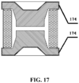
FIG. 17 is an axially sectional view illustrating a gas discharge tube according to an embodiment of the present invention based onEmbodiment 7; - The gas discharge tubes of
Fig.1-16 do not fall under the scope of the present invention defined bypresent claim 1. -
FIG. 12 is an axially sectional view illustrating a gas discharge tube according to a most preferred embodiment. With reference toFIG. 12 , the gas discharge tube shown inFIG. 12 is the same as the gas discharge tube shown inFIG. 8 in the following aspects: electrodes, an insulating tube body, a low-temperature sealing solder or a low-temperature sealing adhesive, a metal ring and a high-temperature solder layer. A difference from the gas discharge tube shown inFIG. 8 is that: the gas discharge tube shown inFIG. 12 further includes aspring apparatus 87. Thespring apparatus 87 has afree end 871. Thefree end 871 is pressed into a retracted state by the electrode adhered with the low-temperature sealing solder or the low-temperature sealing adhesive. When the low-temperature sealing solder or the low-temperature sealing adhesive is melted, a counterforce of thefree end 871 to the electrode is greater than an adhesive force between the electrode and the low-temperature sealing solder or the low-temperature sealing adhesive, so that thefree end 871 extends to pull away the electrode adhered with the low-temperature sealing solder or the low-temperature sealing adhesive. Similarly, when both ends of the gas discharge tube are provided with the low-temperature sealing solder or the low-temperature sealing adhesives, the spring apparatus may be provided with two free ends (not shown). Any one of the free ends may extend to pull away the electrode at the end as long as the low-temperature sealing solder or the low-temperature sealing adhesive at the end is melted. The present embodiment has the advantages as follows. When a large current passes through the gas discharge tube, if the low-temperature sealing solder or the low-temperature sealing adhesive starts to be melted and the adhesive force between the low-temperature sealing solder or the low-temperature sealing adhesive and the electrode is reduced, the equibrium between the counterforce and the adhesive force is broken and the spring apparatus enables the free end to extend to quickly pull away the electrode adhered with the low-temperature sealing solder or the low-temperature sealing adhesive. This results in quick gas leakage and causes an open circuit, so as to further enhance the open circuit protection for a circuit. On the contrary, if no spring apparatus is provided, when the large current passes through the gas discharge tube, instantaneous discharging generates extremely large quantity of heat, which may possibly cause such a phenomenon that the electrode is melted and explodes and sputters before the low-temperature sealing solder or the low-temperature sealing adhesive is melted to leak gas, thereby resulting in a short circuit. - The following embodiments are described in combination with the drawings. It should be noted in advance that a high-temperature solder of the present invention refers to a solder having a melt point higher than 500 °C. The high temperature refers to a temperature higher than 500 °C. The low temperature of the present invention refers to a relatively low temperature relative to the high temperature and is 500 °C or below. The low-temperature sealing solder or the low-temperature sealing adhesive of the present invention refers to a sealing material capable of resisting the low temperature. This material may be melted to deform and even be liquefied in an environment with a temperature higher than the low temperature, resulting in a sealing failure. The insulating tube body of the present invention refers to a glass tube, a ceramic tube or insulating tube bodies made of other materials suitable for being used as the gas discharge tube. The gas discharge tube of the present invention includes a diode, a triode and a multielectrode tube.
- With reference to
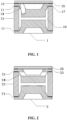
FIG. 1 , an axially sectional view illustrating a gas discharge tube provided byEmbodiment 1 is shown. As shown inFIG. 1 , thegas discharge tube 1 of the present embodiment includes:electrodes 11, aninsulating tube body 12, a low-temperature sealing solder or a low-temperature sealing adhesive 13, aventilation hole 14 and acover plate 15. Theelectrodes 11 are connected in the sealing manner with the insulatingtube body 12 to form a dischargeinner cavity 16. Theventilation hole 14 is axially formed in theelectrodes 11. The inner end of theventilation hole 14 is connected with the dischargeinner cavity 16, and the outer end of theventilation hole 14 is connected with thecover plate 15 through the low-temperature sealing solder or the low-temperature sealing adhesive 13. - Specifically, the
electrodes 11 and the insulatingtube body 12 are sealed by adopting a high-temperature solder 17. Preferably, the high-temperature solder 17 is the silver-copper solder. - Preferably, the low-temperature sealing solder is a low-temperature tin solder or glass solder, and has a melt point of about 350 °C. The low-temperature sealing adhesive is an organic adhesive such as glue.
- In a preferred embodiment, a plurality of ventilation holes 14 are provided, which are all arranged on one electrode. In another preferred embodiment, a plurality of ventilation holes 14 are provided, which are arranged on the electrodes respectively.
- In another preferred embodiment, the
cover plate 15 is a cover plate having a rough surface or a cover plate with a ventilation trench, so as to increase an adhesive force of the low-temperature sealing solder or the low-temperature sealing adhesive 13 on thecover plate 15 and to achieve better sealing effect. Meanwhile, when the low-temperature sealing solder or the low-temperature sealing adhesive 13 is melted, gas in the dischargeinner cavity 16 is easier to leak through the cover plate having the rough surface or the cover plate with the ventilation trench, so that a subsequent circuit is cut off quickly. - The present embodiment has the advantages described below.
- The ventilation hole for connecting the discharge inner cavity with the outside is formed in the gas discharge tube, and the low-temperature sealing solder or the low-temperature sealing adhesive is arranged at the outer end of the ventilating hole. Therefore, the gas discharge tube can implement the overvoltage protection when undergoing a lightning overvoltage. Furthermore, when the gas discharge tube has a temperature rise to a specific temperature under a large current or a long-time overcurrent, the low-temperature sealing solder or the low-temperature sealing adhesive reaches the melt point and starts to be melted, and then the gas starts to leak through the ventilation hole, and external air enters the discharge inner cavity of the gas discharge tube, thereby quickly cutting off the circuit and protecting the circuit.
- With reference to
FIG. 2 , an axially sectional view illustrating a gas discharge tube provided byEmbodiment 2 is shown. As shown inFIG. 2 , thegas discharge tube 2 of the present embodiment includes:electrodes 21, an insulating tube body 22, a low-temperature sealing solder or a low-temperature sealing adhesive 23, aventilation hole 24 and acover plate 25. A difference from the embodiment shown inFIG. 1 is that theventilation hole 24 in the present embodiment is disposed in a radial direction. One end of theradial ventilation hole 24, or the left and right ends of theradial ventilation hole 24, is connected to the discharge inner cavity. Theradial ventilation hole 24 penetrates through a groove in the outer surface of one of theelectrodes 21. Thecover plate 25 for covering the groove is arranged on the groove. Thecover plate 25 is connected to the outer surface of theelectrode 21 through the low-temperature sealing solder or the low-temperature sealing adhesive 23. All other components are the same as those in the embodiment shown inFIG. 1 , so that no more details will be described herein. - The present embodiment has the advantages described below.
- The ventilation hole for connecting the discharge inner cavity with the outside is formed in the gas discharge tube, and the low-temperature sealing solder or the low-temperature sealing adhesive is arranged at the outer end of the ventilating hole. Therefore, the gas discharge tube can implement the overvoltage protection when undergoing a lightning overvoltage. Furthermore, when the gas discharge tube has a temperature rise to a specific temperature under a large current or a long-time overcurrent, the low-temperature sealing solder or the low-temperature sealing adhesive reaches the melt point and starts to be melted, and then the gas starts to leak through the ventilation hole, and external air enters the discharge inner cavity of the gas discharge tube, thereby quickly cutting off the circuit and protecting the circuit.
- With reference to
FIG. 3 , an axially sectional view illustrating a gas discharge tube provided byEmbodiment 3 is shown. As shown inFIG. 3 , thegas discharge tube 3 of the present embodiment includes:electrodes 31, an insulatingtube body 32 and a low-temperature sealing solder or a low-temperature sealing adhesive 33. - Specifically, a disconnection layer is arranged in the middle of the insulating
tube body 32, so that the insulating tube body is divided into two sections along a radial direction. The low-temperature sealing solder or the low-temperature sealing adhesive 33 is arranged on the disconnection layer and connects in the sealing manner the two sections of the insulating tube body. Of course, it also can be understood that the two sections of the insulatingtube body 32 are connected together in the sealing manner through the low-temperature sealing solder or the low-temperature sealing adhesive 33, so that the effect and the principle are the same as those in thepresent embodiment 3. - In a preferred embodiment, the low-temperature sealing solder or the low-
temperature sealing adhesive 33 is arranged in the middle of the disconnection layer, so that in case of a power frequency current, it is easier to abosorb the heat generated by the discharge tube during continuous arc discharging and it is easier to occur a failure of open circuit caused by gas leakage, thereby cutting off a circuit. - As another variation of the present embodiment, a ventilation hole (not shown) also may be provided in the insulating
tube body 32. The outer end of this ventilation hole is connected in the sealing manner with the cover plate through the low-temperature sealing solder or the low-temperature sealing adhesive, so that the effect and the principle are still the same as those of thepresent embodiment 3. - The present embodiment has the advantages described below.
- The disconnection layer is provided in the insulating tube body of the gas discharge tube and is sealed through the low-temperature sealing solder or the low-temperature sealing adhesive. Therefore, the gas discharge tube can implement the overvoltage protection when undergoing a lightning overvoltage. Furthermore, when the gas discharge tube has a temperature rise to a specific temperature under a large current or a long-time overcurrent, the low-temperature sealing solder or the low-temperature sealing adhesive reaches the melt point and starts to be melted, and then the gas starts to leak through the disconnection layer, and external air enters the discharge inner cavity of the gas discharge tube, thereby quickly cutting off the circuit and protecting the circuit.
- Wth reference to
FIG. 4 , an axially sectional view illustrating a gas discharge tube provided byEmbodiment 4 is shown. As shown inFIG. 4 , thegas discharge tube 4 of the present embodiment includes:electrodes 41, an insulatingtube body 42 and a low-temperature sealing solder or a low-temperature sealing adhesive 43. - Specifically, the
gas discharge tube 4 of the present embodiment is a triode, including an upper electrode, a lower electrode and a middle electrode. - The
middle electrode 41 of thegas discharge tube 4 is provided with a disconnection layer for dividing themiddle electrode 41 into two portions. The low-temperature sealing solder or the low-temperature sealing adhesive 43 is arranged in the disconnection layer and connects in the sealing manner the two separated portions of themiddle electrode 41. - The present embodiment has the advantages described below.
- The disconnection layer is provided in the insulating tube body of the gas discharge tube and is sealed through the low-temperature sealing solder or the low-temperature sealing adhesive. Therefore, the gas discharge tube can implement the overvoltage protection when undergoing a lightning overvoltage. Furthermore, when the gas discharge tube has a temperature rise to a specific temperature under a large current or a long-time overcurrent, the low-temperature sealing solder or the low-temperature sealing adhesive reaches the melt point and starts to be melted, and then the gas starts to leak through the disconnection layer, and external air enters the discharge inner cavity of the gas discharge tube, thereby quickly cutting off the circuit and protecting the circuit.
- With reference to
FIG. 5 , an axially sectional view illustrating a gas discharge tube provided byEmbodiment 5 is shown. As shown inFIG. 5 , thegas discharge tube 5 of the present embodiment includes:electrodes 51, an insulatingtube body 52 and a low-temperature sealing solder or alow-temperature sealing adhesive 53. - A difference from the embodiment shown in
FIG. 4 is that the disconnection layer of themiddle electrode 51 in the present embodiment has a shape of a broken line opening, but the disconnection layer in the embodiment shown inFIG. 4 has a shape of a straight line opening. The low-temperature sealing solder or the low-temperature sealing adhesive 53 is arranged on a cross section linearly connected with the discharge inner cavity. All other components are the same as those in the embodiment shown inFIG. 4 , so that no more details will be described herein. - The present embodiment has the advantages described below.
- The broken line opening-shaped disconnection layer is arranged in the middle electrode of the gas discharge tube, and the low-temperature sealing solder or the low-temperature sealing adhesive is used to seal the end of the middle electrode linearly connected with the discharge inner cavity. Therefore, during the reflow soldering of the product, the low-temperature sealing solder or the low-temperature sealing adhesive is not in direct contact with a tin solder layer of an surface-mounted outer electrode, and the opening has a heat dissipation effect. Therefore, during reflow soldering, the low-temperature sealing solder or the low-temperature sealing adhesive is difficult to overheat and damage, and gas leakage does not occur. However, the gas discharge tube can implement the overvoltage protection when undergoing a lightning overvoltage. Furthermore, when the gas discharge tube has a temperature rise to a specific temperature under a large current or a long-time overcurrent, the low-temperature sealing solder or the low-temperature sealing adhesive reaches the melt point and starts to be melted, and then the gas starts to leak through the disconnection layer, and external air enters the discharge inner cavity of the gas discharge tube, thereby quickly cutting off the circuit and protecting the circuit.
- With reference to
FIG. 6 , an axially sectional view of a gas discharge tube provided byEmbodiment 6 is shown. As shown inFIG. 6 , thegas discharge tube 6 of the present embodiment includes:electrodes 61, an insulatingtube body 62 and a low-temperature sealing solder or a low-temperature sealing adhesive 63. - A difference from the embodiment shown in
FIG. 5 is that the low-temperature sealing solder or the low-temperature sealing adhesive 63 in the present embodiment is arranged on a cross section linearly connected with the exterior of the gas discharge tube. All other components are the same as those in the embodiment shown inFIG. 5 , so that no more details will be described herein. - The present embodiment has the advantages described below.
- The broken line-shaped disconnection layer is arranged in the middle electrode of the gas discharge tube, and the low-temperature sealing solder or the low-temperature sealing adhesive is used to seal the end of the middle electrode linearly connected with the exterior of the gas discharge tube, achieving a good sealing effect. The low-temperature sealing solder or the low-temperature sealing adhesive absorbs heat relatively slowly and is difficult to melt and is thus suitable for occasions requiring a relatively low melting speed. The gas discharge tube can implement the overvoltage protection when undergoing a lightning overvoltage. Furthermore, when the gas discharge tube has a temperature rise to a specific temperature under a large current or a long-time overcurrent, the low-temperature sealing solder or the low-temperature sealing adhesive reaches the melt point and starts to be melted, and then the gas starts to leak through the disconnection layer, and external air enters the discharge inner cavity of the gas discharge tube, thereby quickly cutting off the circuit and protecting the circuit.
- With reference to
FIG. 7 , an axially sectional view illustrating a gas discharge tube provided byEmbodiment 7 of the present invention is shown. As shown inFIG. 7 , thegas discharge tube 7 of the present embodiment includes:electrodes 71, an insulatingtube body 72 and low-temperature sealing solder or the low-temperature sealing adhesives 73. - Specifically, the insulating
tube body 72 has an upper end and a lower end which are respectively called a first end and a second end. The first end of the insulatingtube body 72 and the electrodes71 are sealed through the low-temperature sealing solder or the low-temperature sealing adhesive 73. - In a preferred embodiment, the first end of the insulating
tube body 72 is a metalized layer, and the low-temperature sealing solder or the low-temperature sealing adhesive 73 is a low-temperature solder. Preferably, the metalized layer is a molybdenum and manganese layer and is one-layer or multi-layer. Preferably, the low-temperature solder is a low-temperature tin solder. - In another preferred embodiment, the first end of the insulating
tube body 72 is ceramic whiteware, and the low-temperature sealing solder or the low-temperature sealing adhesive 73 is a low-temperature adhesive. Preferably, the low-temperature adhesive 73 is an organic adhesive such as glue. - In a preferred embodiment, the second end of the insulating
tube body 72 and theelectrode 71 are sealed through the low-temperature sealing solder or the low-temperature sealing adhesive 73. - Specifically, the second port is a metalized layer or ceramic whiteware. When the second end is the metalized layer, the low-temperature sealing solder is utilized. When the second end is the ceramic whiteware, the low-temperature sealing adhesive is utilized.
- In a preferred embodiment, the adhesion area between the insulating
tube body 72 and theelectrodes 71 is set, so that the low-temperature sealing solder or the low-temperature sealing adhesives 73 meets a specific melting requirement. Specifically, the specific melting requirement is as follows: in an actual circuit, a melting speed of the low-temperature sealing solder or the low-temperature sealing adhesive 73 is set according to a circuit use environment and the high-temperature resistance performance of a device to be protected. For example, if the normal working temperature of a circuit is 0 to 350 °C, and a certain electronic device to be protected may resist the highest temperature of 370 °C for 30 seconds, the low-temperature sealing solder or the low-temperature sealing adhesive 73 is required to meet the specific melting requirement as follows: the low-temperature sealing solder or the low-temperature sealing adhesive 73 is not melted at a temperature comprised between 0 and 350 °C, start to be melted at a temperature comprised between 350 and 370 °C, and has to be melted within 25 seconds at the temperature of 370 °C, so that the gas discharge tube leaks gas to cut off the circuit to protect the electronic device. - Preferably, the adhesion area between the insulating
tube body 72 and theelectrodes 71 may set in four approaches describe below. - In an
approach 1, a radial width of the insulatingtube body 72 is set to a specific width to enable the contact area between the insulatingtube body 72 and the low-temperature sealing solder or the low-temperature sealing adhesive 73 to be a specific area, so as to facilitate the control of the melting speed of the low-temperature sealing solder or the low-temperature sealing adhesive 73. - In an
approach 2, protrusions having a specific width are arranged at the end of the insulatingtube body 72, which is sealed through the low-temperature sealing solder or the low-temperature sealing adhesive 73, and are adhered with the low-temperature sealing solder or the low-temperature sealing adhesive 73, so as to facilitate the control of the melting speed of the low-temperature sealing solder or the low-temperature sealing adhesive 73. - In an
approach 3, the low-temperature sealing solder or the low-temperature sealing adhesive 73 is set to have a specific width, so as to facilitate the control of the melting speed of the low-temperature sealing solder or the low-temperature sealing adhesive 73. - In an
approach 4, protrusions having a specific width are arranged on the inner surface of theelectrode 71, which is in contact with the low-temperature sealing solder or the low-temperature sealing adhesive 73, and are adhered with the low-temperature sealing solder or the low-temperature sealing adhesive 73, so as to facilitate the melting speed of the low-temperature sealing solder or the low-temperature sealing adhesive 73. - Preferably, leakage-prone points are arranged on the
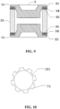
electrodes 71, and/or the low-temperature sealing solder or the low-temperature sealing adhesive 73, and/or the ends of the insulatingtube body 72, and the adhesion area between the insulatingtube 72 and theelectrodes 71 at the leakage-prone points is smaller than that at other positions. One or more leakage-prone points may be arranged. Specifically, with reference toFIG. 10 , an axially sectional view illustrating the low-temperature sealing solder or the low-temperature sealing adhesive 73 of the gas discharge tube provided by the present embodiment is shown. Multiple leakage-prone points 101 are provided in the figure. - Specifically, the leakage-
prone points 101 are positions where the low-temperature sealing solder or the low-temperature sealing adhesive 73 is prone to melt due to the least adhesive force and the least material. The melting causes the gas discharge tube to leak gas to cut off the circuit. - The present embodiment has the advantages described below.
- The ends of the insulating tube body of the present embodiment are sealed through the low-temperature sealing solder or the low-temperature sealing adhesive. Therefore, the gas discharge tube can implement the overvoltage protection when undergoing a lightning overvoltage. Furthermore, when the gas discharge tube has a temperature rise to a specific temperature under a large current or a long-time overcurrent, the low-temperature sealing solder or the low-temperature sealing adhesive reaches the melt point and starts to be melted, and then the gas starts to leak from the discharge inner cavity, and external air enters the discharge inner cavity of the gas discharge tube, thereby quickly cutting off the circuit and protecting the circuit.
- Further, there are provided the following two preferred solutions as preferred solutions of
Embodiment 7. - With reference to
FIG. 16 , an axially sectional view illustrating a gas discharge tube according to a first preferred solution provided byEmbodiment 7 is shown The present embodiment is the same as the embodiment as shown inFIG. 7 in the following aspects:electrodes 161 and an insulatingtube body 162, and that theelectrodes 161 and the insulatingtube body 162 are sealed by adopting low-temperature sealing solder or the low-temperature sealing adhesive 163. A difference is that: aprotective layer 164 having a heat conductivity coefficient less than that of the electrodes is arranged on the outer surface of the low-temperature sealing solder or the low-temperature sealing adhesive 163 on one side of the gas discharge tube. Specifically, the protective layer is a nickel layer, a chromium layer, a layer of other metals or a layer of non-metal, and is arranged on the outer surface of the low-temperature sealing solder or the low-temperature sealing adhesive 163 in an electroplating or bepowder manner. This has the benefits described below. Firstly, when the gas discharge tube is subjected to surface-mounted reflow soldering by a user, a small part of external heat may be transferred to the low-temperature sealing solder or the low-temperature sealing adhesive 163 because the heat conductivity coefficient of the protective layer is small, so as to prevent a failure, caused by a misoperation of open circuit, of the gas discharge tube during the reflow soldering. Secondly, when the gas discharge tube is heated by a large current or a long-time overcurrent, a little part of the heat inside the gas discharge tube is transferred to the outside because the small heat conductivity coefficient is small, and the heat may be more intensively used to melt the low-temperature sealing solder or the low-temperature sealing adhesive, so that the gas discharge tube is enabled to have an open circuit quickly. - With reference to
FIG. 17 , an axially sectional view illustrating a gas discharge tube according to an embodiment of the present invention, based onEmbodiment 7, is shown. - A difference between the present embodiment and the embodiment shown in
FIG. 16 is that:protective layers 174 are arranged on all the outer surfaces of the gas discharge tube except the outer surface of the insulating tube body, i.e., theprotective layers 174 are arranged on the outer surfaces of the electrodes and the low-temperature sealing solder or the low-temperature sealing adhesive. The heat conductivity coefficient of theprotective layers 174 is less than that of the electrodes, so that the heat transferring is relatively slow. Specifically, the protective layers are nickel layers, chromium layers, layers of other metals or layers of non-metal, and are arranged on the outer surfaces of the electrodes and the low-temperature sealing solder or the low-temperature sealing adhesive in an electroplating or bepowder manner. This has the benefits described below. Firsly, when the gas discharge tube is subjected to surface-mounted reflow soldering by a user, since the protective layers have a small heat conductivity coefficient and cover the electrodes having a relatively large heat conductivity coefficient, external heat may be further prevented from being transferred to the low-temperature sealing solder or the low-temperature sealing adhesive, so as to prevent a failure, caused by a misoperation of open circuit, of the gas discharge tube during reflow soldering. Secondly, when the gas discharge tube is heated by a large current or a long-time overcurrent, since the protective layers have a small heat conductivity coefficient and cover the electrodes having a relatively large heat conductivity coefficient, a smaller part of heat inside the gas discharge tube is transferred to the outside, and the heat may be more intensively used to melt the low-temperature sealing solder or the low-temperature sealing adhesive, so that the gas discharge tube is enabled to have an open circuit quickly. - With reference to
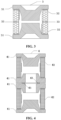
FIG. 8 , an axially sectional view illustrating a gas discharge tube provided byEmbodiment 8 is shown. As shown inFIG. 8 , thegas discharge tube 8 of the present embodiment includes:electrodes 81, an insulatingtube body 82, a low-temperature sealing solder or a low-temperature sealing adhesive 83, ametal ring 84 and high-temperature solder layers 85. The insulatingtube body 82 has an upper end and a lower end which are respectively connected in the sealing manner with the twoelectrodes 81. Specifically, the upper end of the insulatingtube body 82 is connected in the sealing manner with themetal ring 84 through one high-temperature solder layer 85. Themetal ring 84 is connected in the sealing manner with theelectrode 81 through the low-temperature sealing solder or the low-temperature sealing adhesive 83. The lower port of the insulatingtube body 82 is connected in sealing manner with theother electrode 81 through the other high-temperature solder layer 85. - Specifically, the
metal ring 84 may be adapted to high-temperature sealing with the insulatingtube body 82, and may also be adapted to low-temperature sealing with theelectrode 81. In a preferred embodiment, themetal ring 84 is a ring made of non-oxidation copper. In another preferred embodiment, the surface, which is in contact with the low-temperature sealing solder or the low-temperature sealing adhesive 83, of themetal ring 84 is a rough surface. The rough surface causes a large adhesive force, so that themetal ring 84 may be adhered in the sealing manner with the low-temperature sealing solder or the low-temperature sealing adhesive 83 more firmly. In another preferred embodiment, the width of the cross sectional of themetal ring 84 is greater than the width of the cross sectional of the insulatingtube body 82, so as to enlarge a contact area, namely the adhesion area, between themetal ring 84 and the low-temperature sealing solder or the low-temperature sealing adhesive 83, such that themetal ring 84 is adhered in the sealing manner with the low-temperature sealing solder or the low-temperature sealing adhesive 83 more firmly. - Preferably, a metalized layer (not shown), preferably a molybdenum and manganese layer, is arranged at the upper end of the insulating
tube body 82. Themetal ring 84 is connected in the sealing manner to the metalized layer of the insulatingtube body 82 through a high-temperature solder, preferably a silver-copper solder. - The present embodiment has the advantages described below.
- The metal ring is arranged at one end of the insulating tube body of the gas discharge tube of the present embodiment, and the end is sealed by using the low-temperature sealing solder or the low-temperature sealing adhesive. Therefore, the gas discharge tube can implement the overvoltage protection when undergoing a lightning overvoltage. Furthermore, when the gas discharge tube has a temperature rise to a specific temperature under a large current or a long-time overcurrent, the low-temperature sealing solder or the low-temperature sealing adhesive reaches the melt point and starts to be melted, and then the gas starts to leak from the discharge inner cavity, and external air enters the discharge inner cavity of the gas discharge tube, thereby quickly cutting off the circuit and protecting the circuit.
- The present embodiment also has five preferred solutions.
FIG. 11 is an axially sectional view illustrating a gas discharge tube according to a first preferred solution. With reference toFIG. 11 , the gas discharge tube shown inFIG. 11 is the same as the gas discharge tube shown inFIG. 8 in the following aspects: electrodes, an insulating tube body, a low-temperature sealing solder or a low-temperature sealing adhesive, a metal ring and high-temperature solder layers. A difference from the gas discharge tube shown inFIG. 8 is that: the discharge inner cavity of the gas discharge tube shown inFIG. 11 is filled with insulatingparticulate matter 86. Preferably, the insulating particulate matter is quartz sand particles. This solution has the advantages described below. Since the discharge inner cavity is filled with the insulating particulate matter, heat generated by discharging of the discharge inner cavity is mostly absorbed by the insulating particulate matter. When a large current passes through the gas discharge tube, the electrodes at both ends of the discharge inner cavity may not have a sharp temperature rise that causes melting, explosion and sputtering, and there is more time for the low-temperature sealing solder or the low-temperature sealing adhesive to be melted, so that the open circuit protection for a circuit is enhanced. On the contrary, if no quartz sand is added, when the large current passes through the gas discharge tube, instantaneous discharging may generate extremely large quantity of heat which may possibly result in such a phenomenon that the electrode is melted, exploded and sputtered before the low-temperature sealing solder or the low-temperature sealing adhesive is melted and the gas leaks, thereby resulting in a short circuit. -
FIG. 12 is an axially sectional view illustrating a gas discharge tube according to a second preferred solution. With reference toFIG. 12 , the gas discharge tube shown inFIG. 12 is the same as the gas discharge tube shown inFIG. 8 in the following aspects: electrodes, an insulating tube body, a low-temperature sealing solder or a low-temperature sealing adhesive, a metal ring and high-temperature solder layers. A difference from the gas discharge tube shown inFIG. 8 is that: the gas discharge tube shown inFIG. 12 further includes aspring apparatus 87. Thespring apparatus 87 has afree end 871. Thefree end 871 is pressed into a retracted state by the electrode adhered with the low-temperature sealing solder or the low-temperature sealing adhesive. When the low-temperature sealing solder or the low-temperature sealing adhesive is melted, a counterforce of thefree end 871 to the electrode is greater than an adhesive force between the electrode and the low-temperature sealing solder or the low-temperature sealing adhesive, so that thefree end 871 extends to pull away the electrode adhered with the low-temperature sealing solder or the low-temperature sealing adhesive. Similarly, when both ends of the gas discharge tube are provided with the low-temperature sealing solder or the low-temperature sealing adhesive, the spring apparatus may be provided with two free ends (not shown). Any one of the free ends may extend to pull away the electrode at the end as long as the low-temperature sealing solder or the low-temperature sealing adhesive at the end is melted. This solution has the advantages described below. When a large current passes through the gas discharge tube, if the low-temperature sealing solder or the low-temperature sealing adhesive starts to be melted till the adhesive force between the low-temperature sealing solder or the low-temperature sealing adhesive and the electrode is reduced, the free end of the spring apparatus extends because the equilibrium between the counterforce and the adhesive force is broken, so as to quickly pull away the electrode adhered with the low-temperature sealing solder or the low-temperature sealing adhesive, resulting in quick gas leakage, which causes an open circuit, so as to further enhance the open circuit protection for a circuit. On the contrary, if no spring apparatus is provided, when the large current passes through the gas discharge tube, instantaneous discharging generates extremely large quantity of heat which may possibly cause such a phenomenon that the electrode is melted, exploded and sputtered before the low-temperature sealing solder or the low-temperature sealing adhesive is melted to leak gas, thereby resulting in a short circuit. -
FIG. 13 is an axially sectional view illustrating a gas discharge tube according to a third preferred solution. With reference toFIG. 13 , the gas discharge tube shown inFIG. 13 integrates the advantages of the gas discharge tubes shown inFIG. 11 and FIG. 12 , i.e., the spring apparatus is arranged on the gas discharge tube, and the discharge inner cavity is filled with the insulating particulate matter, so as to further ensure that the gas discharge tube, through which a large current passes, may have an open circuit in time to realize dual protection for a circuit. -
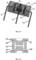
FIG. 14 is an axially sectional view illustrating a gas discharge tube according to a fourth preferred solution provided byEmbodiment 8. With reference toFIG. 14 , the gas discharge tube shown inFIG. 14 is the same as the gas discharge tube shown inFIG. 12 in the following aspects: aspring apparatus 145,electrodes 146, an insulatingtube body 147, a low-temperature sealing solder or a low-temperature sealing adhesive 148, ametal ring 149 and high-temperature solder layers 140. A difference from the gas discharge tube shown inFIG. 12 is that: the gas discharge tube as shown inFIG. 14 includespins 142 respectively connected with the two electrodes, and ashell 141 having acavity 143 for accommodating thespring apparatus 145. Thecavity 143 is further provided with a throughhole 144 communicated with external air. Onepin 142 extends out via the throughhole 144. Preferably, the shell is a ceramic shell. This solution has the advantages described below. When a large current passes through the gas discharge tube, if the low-temperature sealing solder or the low-temperature sealing adhesive starts to be melted till the adhesive force between the low-temperature sealing solder or the low-temperature sealing adhesive and the electrode is reduced, the spring apparatus enables the free end to extend because the equilibrium between the counterforce and the adhesive force is broken, so as to quickly pull away the electrode adhered with the low-temperature sealing solder or the low-temperature sealing adhesive, resulting in quick gas leakage, which causes an open circuit. Meanwhile, the arranged shell prevents the parts which are possibly scattered from falling on the ground when the gas discharge tube is open. -
FIG. 15 is an axially sectional view illustrating a gas discharge tube according to a fifth preferred solution provided byEmbodiment 8. With reference toFIG. 15 , the gas discharge tube shown inFIG. 15 differs from the gas discharge tube according to the fourth preferred solution shown inFIG. 14 is that: the gas discharge tube is a triode provided with twospring apparatuses 155, pins 152 are respectively connected with the three electrodes, and ashell 151 having acavity 153 for accommodating thespring apparatuses 155. Thecavity 153 is further provided with two throughholes 154 communicated with external air. Two of thepins 152 extend out via the throughholes 154. The advantages of this preferred solution are the same as those of the preferred solution shown inFIG. 14 , so that no more details will be described herein. - With reference to
FIG. 9 , an axially sectional view illustrating a gas discharge tube provided by Embodiment 9 is shown. The gas discharge tube 9 includes an insulatingtube body 92,electrodes 91, metal rings 94, low-temperature sealing solder or the low-temperature sealing adhesive 93 and high-temperature solder layers 95. The insulatingtube body 92 has an upper end and a lower end which are respectively connected in the sealing manner with the metal rings 94 through the high-temperature solder layers 95. The metal rings 94 are connected in the sealing manner with theelectrodes 91 through the low-temperature sealing solder or the low-temperature sealing adhesive 93. - It should be noted that except the features that "the lower end of the insulating
tube body 92 is also provided with ametal ring 94 and is connected in the sealing manner with themetal ring 94 through the high-temperature solder layer 95, and themetal ring 94 is connected in the sealing manner with theelectrode 91 through the low-temperature sealing solder or the low-temperature sealing adhesive 93", all other features of the present embodiment are the same as those of the embodiment shown inFIG. 8 , and specifically refer to the embodiment shown inFIG. 8 , so that no more details will be described herein. The each of two ends of the insulatingtube body 92 is provided with a metal ring and the low-temperature sealing solder or the low-temperature sealing adhesive, so that when a temperature rise is caused by overcurrent heat, the gas discharge tube leaks gas more easily to cut off a circuit to further protect the circuit. - The present embodiment has the advantages described below.
- In the gas discharge tube of the present embodiment, metal rings are arranged at the two ends of the insulating tube body, and the ends are sealed by using the low-temperature sealing solder or the low-temperature sealing adhesive. Therefore, the gas discharge tube can implement the overvoltage protection when undergoing a lightning overvoltage. Furthermore, when the gas discharge tube has a temperature rise to a specific temperature under a large current or a long-time overcurrent, the low-temperature sealing solder or the low-temperature sealing adhesive at any end reaches the melt point and starts to be melted, and then the gas starts to leak from the discharge inner cavity, and external air enters the discharge inner cavity of the gas discharge tube, thereby quickly cutting off the circuit and protecting the circuit.
- Apparently, the above-mentioned embodiments are only to clearly describe examples taken, but not intended to limit the implementation. Some technical features in any one of the above-mentioned embodiments may also be applied to other embodiments. For example, the setting of the adhesion area between the insulating tube body and the electrodes, the arrangement of the leakage-prone points, the arrangement of the insulating particulate matter in the discharge inner cavity and the arrangement of the spring apparatus may be all applied into other embodiments. Those ordinarily skilled in the art can further make other changes or variations in different forms on the basis of the above-mentioned descriptions. It is unnecessary and impossible to exemplify all implementation modes herein.
- The gas discharge tube of the present invention may be manufactured and used. Furthermore, when the gas discharge tube has the temperature rise to the specific temperature under a large current or the long-time overcurrent, the low-temperature sealing solder or the low-temperature sealing adhesive at any one of the ends reaches the melt point and starts to be melted, and then gas leaks from the discharge inner cavity, and external air enters the discharge inner cavity of the gas discharge tube, thereby quickly cutting off the circuit and protecting the circuit. The gas discharge tube has beneficial technical effects.
Claims (4)
- A gas discharge tube, comprising at least two electrodes (11, 21, 31, 41, 51, 61, 71, 161, 81, 146, 91) and an insulating tube body (12, 22, 32, 42, 52, 62, 72, 162, 82, 147, 92) which is connected in a sealing manner with the electrodes (11, 21, 31, 41, 51, 61, 71, 161, 81, 146, 91) to form a discharge inner cavity (16), the discharge inner cavity (16) being filled with gas, wherein a low-temperature sealing solder or a low-temperature sealing adhesive (13, 23, 33, 43, 53, 63, 73, 163, 83, 148, 93) for sealing the discharge inner cavity (16) is arranged in the gas discharge tube, the low-temperature sealing solder or low-temperature sealing adhesive (13, 23, 33, 43, 53, 63, 73, 163, 83, 148, 93) being capable of melting at a specific low temperature to cause gas leakage in the discharge inner cavity (16); wherein the low-temperature is 500 °C or below; wherein at least one electrode (11, 21, 31, 41, 51, 61, 71, 161, 81, 146, 91) of the electrodes (11, 21, 31, 41, 51, 61, 71, 161, 81, 146, 91) is connected in the sealing manner with the insulating tube body (12, 22, 32, 42, 52, 62, 72, 162, 82, 147, 92) through the low-temperature sealing solder or the low-temperature sealing adhesive (13, 23, 33, 43, 53, 63, 73, 163, 83, 148, 93);
characterized in that,
protective layers (174) having a heat conductivity coefficient less than that of the electrodes (11, 21, 31, 41, 51, 61, 71, 161, 81, 146, 91) are arranged on outer surfaces of the electrodes (11, 21, 31, 41, 51, 61, 71, 161, 81, 146, 91) and the low-temperature sealing solder or the low-temperature sealing adhesive (13, 23, 33, 43, 53, 63, 73, 163, 83, 148, 93); wherein the protective layers (174) are arranged to reduce heat transferred from an inside of the gas discharge tube to an outside of the the gas discharge tube. - The gas discharge tube according to claim 1, wherein the at least one electrode (11, 21, 31, 41, 51, 61, 71, 161, 81, 146, 91) is connected in the sealing manner with the insulating tube body (12, 22, 32, 42, 52, 62, 72, 162, 82, 147, 92) through the low-temperature sealing solder or the low-temperature sealing adhesive (13, 23, 33, 43, 53, 63, 73, 163, 83, 148, 93) in a following manner: a metalized layer or a metal ring (84, 149, 94) is arranged between the at least one electrode (11, 21, 31, 41, 51, 61, 71, 161, 81, 146, 91) and the insulating tube body (12, 22, 32, 42, 52, 62, 72, 162, 82, 147, 92), and the at least one electrode (11, 21, 31, 41, 51, 61, 71, 161, 81, 146, 91) is connected in the sealing manner with the metalized layer or the metal ring (84, 149, 94) through the low-temperature sealing solder or the low-temperature sealing adhesive (13, 23, 33, 43, 53, 63, 73, 163, 83, 148, 93).
- The gas discharge tube according to claim 2, wherein the gas discharge tube further comprises a spring apparatus (87, 145, 155), the spring apparatus (87, 145, 155) having at least one free end (871), the free end (871) being pressed into a retracted state by the at least one electrode (11, 21, 31, 41, 51, 61, 71, 161, 81, 146, 91) adhered with the low-temperature sealing solder or the low-temperature sealing adhesive (13, 23, 33, 43, 53, 63, 73, 163, 83, 148, 93); when the low-temperature sealing solder or the low-temperature sealing adhesive (13, 23, 33, 43, 53, 63, 73, 163, 83, 148, 93) is melted, a counterforce of the free end (871) to the at least one electrode (11, 21, 31, 41, 51, 61, 71, 161, 81, 146, 91) is greater than an adhesive force between the at least one electrode (11, 21, 31, 41, 51, 61, 71, 161, 81, 146, 91) and the low-temperature sealing solder or the low-temperature sealing adhesive (13, 23, 33, 43, 53, 63, 73, 163, 83, 148, 93), and the free end (871) extends to pull away the at least one electrode (11, 21, 31, 41, 51, 61, 71, 161, 81, 146, 91) adhered with the low-temperature sealing solder or the low-temperature sealing adhesive (13, 23, 33, 43, 53, 63, 73, 163, 83, 148, 93).
- The gas discharge tube according to claim 3, wherein the gas discharge tube further comprises a plurality of pins (142, 152) and a shell (141, 151), the pins (142, 152) are connected with the electrodes (11, 21, 31, 41, 51, 61, 71, 161, 81, 146, 91) respectively, the shell (141, 151) having a cavity (143, 153) for accommodating the spring apparatus (87, 145, 155), the cavity (143, 153) being further provided with a through hole (144, 154) communicated with external air, at least one pin of the pins (142, 152) extending out via the through hole.
Applications Claiming Priority (3)
| Application Number | Priority Date | Filing Date | Title |
|---|---|---|---|
| CN201510882495.XA CN105374653A (en) | 2015-12-04 | 2015-12-04 | Gas discharge tube |
| CN201610190179.0A CN105826149B (en) | 2015-12-04 | 2016-03-30 | a gas discharge tube |
| PCT/CN2016/088517 WO2017092304A1 (en) | 2015-12-04 | 2016-07-05 | Gas discharge tube |
Publications (4)
| Publication Number | Publication Date |
|---|---|
| EP3385975A1 EP3385975A1 (en) | 2018-10-10 |
| EP3385975A4 EP3385975A4 (en) | 2019-08-07 |
| EP3385975B1 true EP3385975B1 (en) | 2024-08-14 |
| EP3385975C0 EP3385975C0 (en) | 2024-08-14 |
Family
ID=55376745
Family Applications (1)
| Application Number | Title | Priority Date | Filing Date |
|---|---|---|---|
| EP16869617.7A Active EP3385975B1 (en) | 2015-12-04 | 2016-07-05 | Gas discharge tube |
Country Status (8)
| Country | Link |
|---|---|
| US (1) | US10943757B2 (en) |
| EP (1) | EP3385975B1 (en) |
| JP (1) | JP6761046B2 (en) |
| KR (1) | KR102142794B1 (en) |
| CN (3) | CN105374653A (en) |
| BR (1) | BR112018011290B1 (en) |
| MX (1) | MX391577B (en) |
| WO (1) | WO2017092304A1 (en) |
Families Citing this family (17)
| Publication number | Priority date | Publication date | Assignee | Title |
|---|---|---|---|---|
| CN105374653A (en) * | 2015-12-04 | 2016-03-02 | 深圳市槟城电子有限公司 | Gas discharge tube |
| CN106128910A (en) * | 2016-07-13 | 2016-11-16 | 深圳市槟城电子有限公司 | A kind of thin patch gas-discharge tube |
| CN106329316B (en) * | 2016-11-07 | 2018-03-02 | 深圳市瑞隆源电子有限公司 | A kind of open loop failure mode discharge tube |
| CN106451397A (en) * | 2016-11-30 | 2017-02-22 | 东莞市阿甘半导体有限公司 | Lightning protection device |
| CN109755932A (en) * | 2017-11-06 | 2019-05-14 | 东莞市阿甘半导体有限公司 | A kind of AC power surge protection device and electronic equipment |
| CN109936124A (en) * | 2017-12-15 | 2019-06-25 | 中兴通讯股份有限公司 | A kind of Security Unit |
| CN108091531B (en) * | 2018-01-22 | 2024-08-30 | 深圳市槟城电子股份有限公司 | Gas discharge tube and overvoltage protection device |
| CN108305822B (en) * | 2018-01-23 | 2021-03-09 | 深圳市槟城电子有限公司 | Gas discharge tube, overvoltage protection device, and method for manufacturing gas discharge tube |
| CN108257835B (en) * | 2018-02-07 | 2020-08-11 | 深圳市槟城电子有限公司 | Gas discharge tube and overvoltage protection device |
| CN109038221B (en) * | 2018-07-30 | 2019-11-08 | 华格电子(昆山)有限公司 | Active overvoltage protection gap with plug-in function in gas environment |
| DE102018118906B3 (en) * | 2018-08-03 | 2019-10-17 | Phoenix Contact Gmbh & Co. Kg | Surge protection device |
| DE102018118898B3 (en) | 2018-08-03 | 2019-10-24 | Phoenix Contact Gmbh & Co. Kg | Retaining arrangement and arrangement of at least two staple bursts |
| CN109510186B (en) * | 2018-12-05 | 2024-07-23 | 江苏东光电子有限公司 | Power supply lightning protection device capable of improving follow current blocking capacity |
| CN113131341A (en) * | 2021-04-21 | 2021-07-16 | 深圳市瑞隆源电子有限公司 | Gas discharge tube and method for manufacturing the same |
| CN113488362B (en) * | 2021-06-01 | 2024-07-23 | 巨民生 | Gas discharge tube and overvoltage protection device thereof |
| CN113808894B (en) * | 2021-09-14 | 2025-03-11 | 深圳市瑞隆源电子有限公司 | Overvoltage protection device, gas discharge tube and preparation method thereof |
| KR20240122902A (en) * | 2021-12-29 | 2024-08-13 | 본스인코오포레이티드 | MOV/GDT devices with low voltage gas discharge characteristics |
Citations (4)
| Publication number | Priority date | Publication date | Assignee | Title |
|---|---|---|---|---|
| JPH0439881A (en) * | 1990-06-06 | 1992-02-10 | Hyogo Nippon Denki Kk | Discharge tube |
| JPH0765930A (en) * | 1993-08-23 | 1995-03-10 | Mitsubishi Materials Corp | Discharge type surge absorber |
| EP1115187A2 (en) * | 2000-01-05 | 2001-07-11 | Shinko Electric Industries Co. Ltd. | Three-electrode-discharge surge arrester |
| JP2007242242A (en) * | 2006-03-03 | 2007-09-20 | Sanyo Electric Industries Co Ltd | Lightning arresting element and its manufacturing method |
Family Cites Families (17)
| Publication number | Priority date | Publication date | Assignee | Title |
|---|---|---|---|---|
| US2370082A (en) * | 1940-09-27 | 1945-02-20 | Westinghouse Electric & Mfg Co | Electric discharge device |
| GB596083A (en) * | 1944-07-27 | 1947-12-29 | British Thomson Houston Co Ltd | Improvements in and relating to lightning arresters |
| US4282557A (en) * | 1979-10-29 | 1981-08-04 | General Electric Company | Surge voltage arrester housing having a fragible section |
| DE2951467C2 (en) * | 1979-12-20 | 1982-06-24 | Siemens AG, 1000 Berlin und 8000 München | Surge arrester with air spark gap connected in parallel |
| US4371911A (en) * | 1980-05-16 | 1983-02-01 | The M-O Valve Company Limited | Excess voltage arresters |
| JPH06124687A (en) * | 1992-10-09 | 1994-05-06 | Hamamatsu Photonics Kk | Discharge tube |
| DE9321371U1 (en) * | 1993-04-21 | 1997-09-04 | Siemens AG, 80333 München | Gas discharge surge arrester |
| DE10162916A1 (en) * | 2001-12-20 | 2003-07-10 | Epcos Ag | Spring clip, surge arrester with the spring clip and arrangement of a surge arrester |
| US6992440B2 (en) * | 2004-02-26 | 2006-01-31 | Asahi Glass Company, Limited | Light-emitting device and process for its production |
| DE102005021303A1 (en) * | 2005-05-09 | 2006-11-16 | Patent-Treuhand-Gesellschaft für elektrische Glühlampen mbH | Manufacturing method for dielectrically restricted discharge lamp e.g. for monitors and display screens, has flat discharge vessel sealed by solder glass |
| DE102007056183B4 (en) * | 2007-11-21 | 2020-01-30 | Tdk Electronics Ag | Surge arrester with thermal overload protection, use of a surge arrester and method for protecting a surge arrester |
| CN101882757A (en) * | 2009-05-06 | 2010-11-10 | 深圳市槟城电子有限公司 | High-intensity arc voltage gas electrical discharge tube |
| CN102184824B (en) * | 2011-04-13 | 2013-08-14 | 深圳市硕凯电子有限公司 | Multipath gas-discharge tube |
| CN103441053B (en) * | 2013-03-22 | 2016-03-23 | 深圳市槟城电子有限公司 | Integrated gas discharge tube and preparation method thereof |
| CN105374653A (en) * | 2015-12-04 | 2016-03-02 | 深圳市槟城电子有限公司 | Gas discharge tube |
| CN205177764U (en) * | 2015-12-04 | 2016-04-20 | 深圳市槟城电子有限公司 | Gas discharge tube |
| CN105610049B (en) * | 2016-02-25 | 2024-05-17 | 深圳市槟城电子股份有限公司 | Gas discharge tube |
-
2015
- 2015-12-04 CN CN201510882495.XA patent/CN105374653A/en active Pending
-
2016
- 2016-03-30 CN CN201811479735.1A patent/CN109686634B/en active Active
- 2016-03-30 CN CN201610190179.0A patent/CN105826149B/en active Active
- 2016-07-05 BR BR112018011290-9A patent/BR112018011290B1/en active IP Right Grant
- 2016-07-05 EP EP16869617.7A patent/EP3385975B1/en active Active
- 2016-07-05 WO PCT/CN2016/088517 patent/WO2017092304A1/en not_active Ceased
- 2016-07-05 KR KR1020187019069A patent/KR102142794B1/en active Active
- 2016-07-05 MX MX2018006766A patent/MX391577B/en unknown
- 2016-07-05 US US15/781,440 patent/US10943757B2/en active Active
- 2016-07-05 JP JP2018548254A patent/JP6761046B2/en active Active
Patent Citations (4)
| Publication number | Priority date | Publication date | Assignee | Title |
|---|---|---|---|---|
| JPH0439881A (en) * | 1990-06-06 | 1992-02-10 | Hyogo Nippon Denki Kk | Discharge tube |
| JPH0765930A (en) * | 1993-08-23 | 1995-03-10 | Mitsubishi Materials Corp | Discharge type surge absorber |
| EP1115187A2 (en) * | 2000-01-05 | 2001-07-11 | Shinko Electric Industries Co. Ltd. | Three-electrode-discharge surge arrester |
| JP2007242242A (en) * | 2006-03-03 | 2007-09-20 | Sanyo Electric Industries Co Ltd | Lightning arresting element and its manufacturing method |
Also Published As
| Publication number | Publication date |
|---|---|
| BR112018011290A2 (en) | 2018-11-27 |
| EP3385975A1 (en) | 2018-10-10 |
| MX391577B (en) | 2025-03-21 |
| CN109686634A (en) | 2019-04-26 |
| WO2017092304A1 (en) | 2017-06-08 |
| CN109686634B (en) | 2021-02-09 |
| KR20180098571A (en) | 2018-09-04 |
| US20200279712A1 (en) | 2020-09-03 |
| JP6761046B2 (en) | 2020-09-23 |
| CN105826149B (en) | 2019-03-15 |
| BR112018011290B1 (en) | 2023-03-28 |
| EP3385975C0 (en) | 2024-08-14 |
| CN105826149A (en) | 2016-08-03 |
| US10943757B2 (en) | 2021-03-09 |
| MX2018006766A (en) | 2018-11-09 |
| JP2019501507A (en) | 2019-01-17 |
| EP3385975A4 (en) | 2019-08-07 |
| CN105374653A (en) | 2016-03-02 |
| KR102142794B1 (en) | 2020-08-07 |
Similar Documents
| Publication | Publication Date | Title |
|---|---|---|
| EP3385975B1 (en) | Gas discharge tube | |
| US8502637B2 (en) | Surge protective device with thermal decoupler and arc suppression | |
| KR100867492B1 (en) | Overvoltage arrester | |
| US10965121B2 (en) | Integrated thermally protected varistor and discharge tube | |
| BRPI0605257B1 (en) | OVERVOLTAGE PROTECTIVE DEVICE AND METHOD FOR PROVIDING OVERVOLTAGE PROTECTION | |
| JP2015185843A (en) | Surge protector | |
| US20160086757A1 (en) | Device Comprising a Thermal Fuse and a Resistor | |
| WO2006063503A1 (en) | Varistor with an alloy-type temperature fuse | |
| US9431158B2 (en) | Barrel-shaped fireproof and explosion-proof surge protection device with over-temperature protection function | |
| US20110057763A1 (en) | Voltage Dependent Resistor with Overheated Protection Structure | |
| CN105610049B (en) | Gas discharge tube | |
| US20070200657A1 (en) | Thermal fuse varistor assembly with an insulating glass passivation layer | |
| US9514865B2 (en) | Multi-contact element for a varistor | |
| CN103400730B (en) | Protection device with over-temperature and over-current double-layer protection | |
| CN108091531B (en) | Gas discharge tube and overvoltage protection device | |
| CN105470089B (en) | Gas discharge tube and metallized electrode used for same | |
| CN205177764U (en) | Gas discharge tube | |
| WO2020071203A1 (en) | Protective element | |
| US12211632B2 (en) | TMOV device | |
| CN205901288U (en) | A Composite Gas Discharge Tube | |
| CN205751735U (en) | A kind of varistor of organic alloy type double protection | |
| CN207426400U (en) | A kind of identifiable non-follow current gas discharge tube | |
| JP6170466B2 (en) | Surge protector | |
| CN105957788B (en) | Composite gas discharge tube | |
| CN103617935A (en) | Fuse |
Legal Events
| Date | Code | Title | Description |
|---|---|---|---|
| STAA | Information on the status of an ep patent application or granted ep patent |
Free format text: STATUS: THE INTERNATIONAL PUBLICATION HAS BEEN MADE |
|
| PUAI | Public reference made under article 153(3) epc to a published international application that has entered the european phase |
Free format text: ORIGINAL CODE: 0009012 |
|
| STAA | Information on the status of an ep patent application or granted ep patent |
Free format text: STATUS: REQUEST FOR EXAMINATION WAS MADE |
|
| 17P | Request for examination filed |
Effective date: 20180618 |
|
| AK | Designated contracting states |
Kind code of ref document: A1 Designated state(s): AL AT BE BG CH CY CZ DE DK EE ES FI FR GB GR HR HU IE IS IT LI LT LU LV MC MK MT NL NO PL PT RO RS SE SI SK SM TR |
|
| AX | Request for extension of the european patent |
Extension state: BA ME |
|
| DAV | Request for validation of the european patent (deleted) | ||
| DAX | Request for extension of the european patent (deleted) | ||
| A4 | Supplementary search report drawn up and despatched |
Effective date: 20190710 |
|
| RIC1 | Information provided on ipc code assigned before grant |
Ipc: H01J 17/18 20120101AFI20190704BHEP Ipc: H01T 1/08 20060101ALI20190704BHEP Ipc: H01T 1/15 20060101ALI20190704BHEP |
|
| STAA | Information on the status of an ep patent application or granted ep patent |
Free format text: STATUS: EXAMINATION IS IN PROGRESS |
|
| 17Q | First examination report despatched |
Effective date: 20211108 |
|
| REG | Reference to a national code |
Ref country code: DE Ref legal event code: R079 Ref document number: 602016088938 Country of ref document: DE Free format text: PREVIOUS MAIN CLASS: H01J0017180000 Ipc: H01T0001150000 Ref country code: DE Ref legal event code: R079 Free format text: PREVIOUS MAIN CLASS: H01J0017180000 Ipc: H01T0001150000 |
|
| GRAP | Despatch of communication of intention to grant a patent |
Free format text: ORIGINAL CODE: EPIDOSNIGR1 |
|
| STAA | Information on the status of an ep patent application or granted ep patent |
Free format text: STATUS: GRANT OF PATENT IS INTENDED |
|
| RIC1 | Information provided on ipc code assigned before grant |
Ipc: H01T 4/16 20060101ALI20240415BHEP Ipc: H01T 4/12 20060101ALI20240415BHEP Ipc: H01T 1/08 20060101ALI20240415BHEP Ipc: H01J 17/18 20120101ALI20240415BHEP Ipc: H01T 1/15 20060101AFI20240415BHEP |
|
| INTG | Intention to grant announced |
Effective date: 20240517 |
|
| GRAS | Grant fee paid |
Free format text: ORIGINAL CODE: EPIDOSNIGR3 |
|
| GRAA | (expected) grant |
Free format text: ORIGINAL CODE: 0009210 |
|
| STAA | Information on the status of an ep patent application or granted ep patent |
Free format text: STATUS: THE PATENT HAS BEEN GRANTED |
|
| AK | Designated contracting states |
Kind code of ref document: B1 Designated state(s): AL AT BE BG CH CY CZ DE DK EE ES FI FR GB GR HR HU IE IS IT LI LT LU LV MC MK MT NL NO PL PT RO RS SE SI SK SM TR |
|
| REG | Reference to a national code |
Ref country code: GB Ref legal event code: FG4D |
|
| REG | Reference to a national code |
Ref country code: CH Ref legal event code: EP |
|
| REG | Reference to a national code |
Ref country code: DE Ref legal event code: R096 Ref document number: 602016088938 Country of ref document: DE |
|
| REG | Reference to a national code |
Ref country code: IE Ref legal event code: FG4D |
|
| U01 | Request for unitary effect filed |
Effective date: 20240911 |
|
| U07 | Unitary effect registered |
Designated state(s): AT BE BG DE DK EE FI FR IT LT LU LV MT NL PT RO SE SI Effective date: 20240926 |
|
| PG25 | Lapsed in a contracting state [announced via postgrant information from national office to epo] |
Ref country code: NO Free format text: LAPSE BECAUSE OF FAILURE TO SUBMIT A TRANSLATION OF THE DESCRIPTION OR TO PAY THE FEE WITHIN THE PRESCRIBED TIME-LIMIT Effective date: 20241114 |
|
| PG25 | Lapsed in a contracting state [announced via postgrant information from national office to epo] |
Ref country code: GR Free format text: LAPSE BECAUSE OF FAILURE TO SUBMIT A TRANSLATION OF THE DESCRIPTION OR TO PAY THE FEE WITHIN THE PRESCRIBED TIME-LIMIT Effective date: 20241115 Ref country code: PL Free format text: LAPSE BECAUSE OF FAILURE TO SUBMIT A TRANSLATION OF THE DESCRIPTION OR TO PAY THE FEE WITHIN THE PRESCRIBED TIME-LIMIT Effective date: 20240814 |
|
| PG25 | Lapsed in a contracting state [announced via postgrant information from national office to epo] |
Ref country code: IS Free format text: LAPSE BECAUSE OF FAILURE TO SUBMIT A TRANSLATION OF THE DESCRIPTION OR TO PAY THE FEE WITHIN THE PRESCRIBED TIME-LIMIT Effective date: 20241214 |
|
| PG25 | Lapsed in a contracting state [announced via postgrant information from national office to epo] |
Ref country code: HR Free format text: LAPSE BECAUSE OF FAILURE TO SUBMIT A TRANSLATION OF THE DESCRIPTION OR TO PAY THE FEE WITHIN THE PRESCRIBED TIME-LIMIT Effective date: 20240814 |
|
| PG25 | Lapsed in a contracting state [announced via postgrant information from national office to epo] |
Ref country code: RS Free format text: LAPSE BECAUSE OF FAILURE TO SUBMIT A TRANSLATION OF THE DESCRIPTION OR TO PAY THE FEE WITHIN THE PRESCRIBED TIME-LIMIT Effective date: 20241114 Ref country code: ES Free format text: LAPSE BECAUSE OF FAILURE TO SUBMIT A TRANSLATION OF THE DESCRIPTION OR TO PAY THE FEE WITHIN THE PRESCRIBED TIME-LIMIT Effective date: 20240814 |
|
| PG25 | Lapsed in a contracting state [announced via postgrant information from national office to epo] |
Ref country code: RS Free format text: LAPSE BECAUSE OF FAILURE TO SUBMIT A TRANSLATION OF THE DESCRIPTION OR TO PAY THE FEE WITHIN THE PRESCRIBED TIME-LIMIT Effective date: 20241114 Ref country code: PL Free format text: LAPSE BECAUSE OF FAILURE TO SUBMIT A TRANSLATION OF THE DESCRIPTION OR TO PAY THE FEE WITHIN THE PRESCRIBED TIME-LIMIT Effective date: 20240814 Ref country code: NO Free format text: LAPSE BECAUSE OF FAILURE TO SUBMIT A TRANSLATION OF THE DESCRIPTION OR TO PAY THE FEE WITHIN THE PRESCRIBED TIME-LIMIT Effective date: 20241114 Ref country code: IS Free format text: LAPSE BECAUSE OF FAILURE TO SUBMIT A TRANSLATION OF THE DESCRIPTION OR TO PAY THE FEE WITHIN THE PRESCRIBED TIME-LIMIT Effective date: 20241214 Ref country code: HR Free format text: LAPSE BECAUSE OF FAILURE TO SUBMIT A TRANSLATION OF THE DESCRIPTION OR TO PAY THE FEE WITHIN THE PRESCRIBED TIME-LIMIT Effective date: 20240814 Ref country code: GR Free format text: LAPSE BECAUSE OF FAILURE TO SUBMIT A TRANSLATION OF THE DESCRIPTION OR TO PAY THE FEE WITHIN THE PRESCRIBED TIME-LIMIT Effective date: 20241115 Ref country code: ES Free format text: LAPSE BECAUSE OF FAILURE TO SUBMIT A TRANSLATION OF THE DESCRIPTION OR TO PAY THE FEE WITHIN THE PRESCRIBED TIME-LIMIT Effective date: 20240814 |
|
| PG25 | Lapsed in a contracting state [announced via postgrant information from national office to epo] |
Ref country code: SM Free format text: LAPSE BECAUSE OF FAILURE TO SUBMIT A TRANSLATION OF THE DESCRIPTION OR TO PAY THE FEE WITHIN THE PRESCRIBED TIME-LIMIT Effective date: 20240814 |
|
| PG25 | Lapsed in a contracting state [announced via postgrant information from national office to epo] |
Ref country code: CZ Free format text: LAPSE BECAUSE OF FAILURE TO SUBMIT A TRANSLATION OF THE DESCRIPTION OR TO PAY THE FEE WITHIN THE PRESCRIBED TIME-LIMIT Effective date: 20240814 |
|
| PG25 | Lapsed in a contracting state [announced via postgrant information from national office to epo] |
Ref country code: SK Free format text: LAPSE BECAUSE OF FAILURE TO SUBMIT A TRANSLATION OF THE DESCRIPTION OR TO PAY THE FEE WITHIN THE PRESCRIBED TIME-LIMIT Effective date: 20240814 |
|
| PLBE | No opposition filed within time limit |
Free format text: ORIGINAL CODE: 0009261 |
|
| STAA | Information on the status of an ep patent application or granted ep patent |
Free format text: STATUS: NO OPPOSITION FILED WITHIN TIME LIMIT |
|
| 26N | No opposition filed |
Effective date: 20250515 |
|
| U20 | Renewal fee for the european patent with unitary effect paid |
Year of fee payment: 10 Effective date: 20250728 |