KR20180098563A - COMPONENTS FOR FUEL INJECTION SYSTEM, AND METHOD FOR MANUFACTURING COMPONENTS OF FUEL INJECTION SYSTEM - Google Patents
COMPONENTS FOR FUEL INJECTION SYSTEM, AND METHOD FOR MANUFACTURING COMPONENTS OF FUEL INJECTION SYSTEM Download PDFInfo
- Publication number
- KR20180098563A KR20180098563A KR1020187018516A KR20187018516A KR20180098563A KR 20180098563 A KR20180098563 A KR 20180098563A KR 1020187018516 A KR1020187018516 A KR 1020187018516A KR 20187018516 A KR20187018516 A KR 20187018516A KR 20180098563 A KR20180098563 A KR 20180098563A
- Authority
- KR
- South Korea
- Prior art keywords
- section
- longitudinal
- tubular section
- fuel injection
- curvature
- Prior art date
- Legal status (The legal status is an assumption and is not a legal conclusion. Google has not performed a legal analysis and makes no representation as to the accuracy of the status listed.)
- Withdrawn
Links
Images


Classifications
-
- F—MECHANICAL ENGINEERING; LIGHTING; HEATING; WEAPONS; BLASTING
- F02—COMBUSTION ENGINES; HOT-GAS OR COMBUSTION-PRODUCT ENGINE PLANTS
- F02M—SUPPLYING COMBUSTION ENGINES IN GENERAL WITH COMBUSTIBLE MIXTURES OR CONSTITUENTS THEREOF
- F02M55/00—Fuel-injection apparatus characterised by their fuel conduits or their venting means; Arrangements of conduits between fuel tank and pump F02M37/00
- F02M55/02—Conduits between injection pumps and injectors, e.g. conduits between pump and common-rail or conduits between common-rail and injectors
-
- B—PERFORMING OPERATIONS; TRANSPORTING
- B29—WORKING OF PLASTICS; WORKING OF SUBSTANCES IN A PLASTIC STATE IN GENERAL
- B29C—SHAPING OR JOINING OF PLASTICS; SHAPING OF MATERIAL IN A PLASTIC STATE, NOT OTHERWISE PROVIDED FOR; AFTER-TREATMENT OF THE SHAPED PRODUCTS, e.g. REPAIRING
- B29C53/00—Shaping by bending, folding, twisting, straightening or flattening; Apparatus therefor
- B29C53/02—Bending or folding
- B29C53/08—Bending or folding of tubes or other profiled members
- B29C53/083—Bending or folding of tubes or other profiled members bending longitudinally, i.e. modifying the curvature of the tube axis
-
- F—MECHANICAL ENGINEERING; LIGHTING; HEATING; WEAPONS; BLASTING
- F02—COMBUSTION ENGINES; HOT-GAS OR COMBUSTION-PRODUCT ENGINE PLANTS
- F02M—SUPPLYING COMBUSTION ENGINES IN GENERAL WITH COMBUSTIBLE MIXTURES OR CONSTITUENTS THEREOF
- F02M55/00—Fuel-injection apparatus characterised by their fuel conduits or their venting means; Arrangements of conduits between fuel tank and pump F02M37/00
- F02M55/004—Joints; Sealings
- F02M55/005—Joints; Sealings for high pressure conduits, e.g. connected to pump outlet or to injector inlet
-
- F—MECHANICAL ENGINEERING; LIGHTING; HEATING; WEAPONS; BLASTING
- F02—COMBUSTION ENGINES; HOT-GAS OR COMBUSTION-PRODUCT ENGINE PLANTS
- F02M—SUPPLYING COMBUSTION ENGINES IN GENERAL WITH COMBUSTIBLE MIXTURES OR CONSTITUENTS THEREOF
- F02M2200/00—Details of fuel-injection apparatus, not otherwise provided for
- F02M2200/90—Selection of particular materials
- F02M2200/9053—Metals
Landscapes
- Engineering & Computer Science (AREA)
- Mechanical Engineering (AREA)
- Chemical & Material Sciences (AREA)
- Combustion & Propulsion (AREA)
- General Engineering & Computer Science (AREA)
- Fuel-Injection Apparatus (AREA)
Abstract
연료 분사 시스템, 특히 고압 연료 분사 시스템용 구성요소(1)는 적어도 부분적으로 관형으로 형성되는 본체(2)를 포함한다. 본체(2)의 관형 섹션(5)은, 관형 섹션(5)의 횡단면(8)을 수직으로 관통하는 관형 섹션(5)의 길이 방향 축(7')을 따라서 길이 방향 굽힘부(6)를 포함한다. 본체(2)는, 길이 방향 굽힘부(6) 상에서 관형 섹션(5)의 횡단면(8)의 타원도(x)가 감소되고 및/또는 8% 미만 이도록 관형 섹션(5)의 길이 방향 굽힘부(6) 상에 형성된다.The fuel injection system, in particular the component (1) for a high pressure fuel injection system, comprises a body (2) at least partly formed in a tubular form. The tubular section 5 of the body 2 has a longitudinal bend 6 along the longitudinal axis 7 'of the tubular section 5 passing vertically through the transverse section 8 of the tubular section 5 . The main body 2 has a longitudinal bend 6 of the tubular section 5 so that the ellipticity x of the cross section 8 of the tubular section 5 on the longitudinal bend 6 is reduced and / (6).

Description
본 발명은 연료 분사 시스템, 특히 고압 연료 분사 시스템용 구성요소, 연료 분사 시스템, 특히 고압 연료 분사 시스템의 구성요소의 제조 방법, 및 상기 방법으로 제조되는 구성요소에 관한 것이다. 특히 본 발명은, 예컨대 연료 분배기를 통해 고압 연료가 다수의 인젝터로 분배되고 이들 인젝터로부터 바람직하게는 직접 내연기관의 연소실들 내로 분사되는, 자동차들의 연료 분사 시스템들의 분야에 관한 것이다.The present invention relates to a fuel injection system, in particular a component for a high pressure fuel injection system, a fuel injection system, in particular a method of manufacturing a component of a high pressure fuel injection system, and a component manufactured by the method. In particular, the present invention relates to the field of fuel injection systems for automobiles, in which high-pressure fuel is distributed, for example through a fuel distributor, to a plurality of injectors and is preferably injected from these injectors directly into the combustion chambers of the internal combustion engine.
DE 101 23 234 A1호로부터, 최적화된 기하구조를 갖는 연료 고압 어큐뮬레이터가 공지되어 있다. 공지된 연료 고압 어큐뮬레이터는, 다수의 연결 개구부를 구비하는 중공 본체를 포함한다. 연료 고압 어큐뮬레이터의 내고압성을 높이기 위해, 본체의 어큐뮬레이터 챔버는 원통형, 타원형 또는 다각형 횡단면을 갖고, 본체는 횡단면으로 볼 때 원통형, 타원형 또는 다각형 외부 윤곽을 갖는다.From DE 101 23 234 A1, a fuel high pressure accumulator having an optimized geometry is known. A known fuel high pressure accumulator includes a hollow body having a plurality of connecting openings. To increase the high pressure resistance of the fuel high pressure accumulator, the accumulator chamber of the body has a cylindrical, elliptical or polygonal cross section, and the body has a cylindrical, elliptical or polygonal outer contour as viewed in cross section.
본 발명의 과제는, 구성 및 기능성이 향상되게 하며, 특히 강도 또는 저항성이 향상되어 유효수명에 걸쳐 유지되게 하는 연료 분사 시스템용 구성요소 및 이 구성요소의 제조 방법을 제공하는 것이다.An object of the present invention is to provide a component for a fuel injection system and a method of manufacturing the component, which makes it possible to improve the constitution and the functionality, in particular, to improve the strength or resistance and to be maintained over the useful life.
청구항 제 1 항의 특징들을 갖는 본 발명에 따른 구성요소, 청구항 제 9 항의 특징들을 갖는 방법, 및 청구항 제 9 항에 따른 방법에 따라서 제조되는 구성요소는 향상된 구성 및 기능성이 가능해진다는 장점을 갖는다. 특히 강도 또는 저항성이 향상되어 유효 수명에 걸쳐 유지될 수 있다.The components according to the invention having the features of
종속 청구항들에 제시된 조치들에 의해, 청구항 제 1 항에 제시된 구성요소, 청구항 제 9 항에 제시된 방법, 및 청구항 제 10 항에 제시된 구성요소의 바람직한 개선예들이 가능하다.By the measures set forth in the dependent claims, it is possible to make the preferred elements of the components recited in
연료 분사 시스템의 경우, 연료 분배기가 제공되며, 특히 일측에서 적어도 하나의 펌프와 연료 분배기를 연결하고 타측에서는 일반적으로 다수 개인 연료 분사 밸브와 상기 연료 분배기를 연결하는 관형 연료 블록, 즉 일체형 또는 다체형 배관부(tubing)가 제공될 수 있다. 연료 분사 시스템의 구성에 따라서, 2개 또는 원칙상 그보다 많은 연료 분배기가 제공될 수 있으며, 이들 연료 분배기는 마찬가지로 서로 연결될 수 있다. 특히 엔진룸 내의 제한된 장착 공간 조건으로 인해, 배관부 또는 배관부의 부재들 또는 관형 연료 분배기와 같은 상기 구성요소들이 1회 또는 수회 한 방향 또는 다수의 방향으로 하나 또는 다수의 상이한 굽힘 각도(bending angle)로 굽혀질 수 있다. 상기 굽힘이 나타나는 구성요소의 관형 본체의 경우, 굽힘 시 굽힘 영역에서 횡단면이 변형되기도 한다. 예컨대 원주에 걸쳐 일정한 벽 두께를 갖는 관형 본체는, 굽힘 후에, 굽힘 동안 작용하던 인장력 및 압축력으로 인한 재료의 소성 변형에 의해 발생하는 타원형 횡단면을 가질 수도 있다. 일반적으로 이 경우 굽힘에 의해 재료의 피로가 생기고 강성이 감소하는 문제가 나타난다. 다소 이상적으로 둥근 횡단면으로부터 원주에 걸쳐 일정하지 않은 벽 두께를 갖는 타원형 횡단면으로의 소성 변형은 관형 부품의 부하 지지력의 국소적 감소를 야기한다. 작동 중에 발생하며 예컨대 유압 압력 또는 기계적 진동에 의해 야기되는 부하는 유효수명에 걸쳐 부품 노후화를 일으키고, 굽힘에 의해 야기된 상대적으로 더 낮은 강도는 조기 고장을 야기하거나 또는 적어도 유효수명을 감소시킬 위험이 있다.In the case of a fuel injection system, a fuel distributor is provided, in particular a tubular fuel block connecting at least one pump and a fuel distributor at one side and a plurality of generally common fuel injection valves at the other side, Tubing may be provided. Depending on the configuration of the fuel injection system, two or, in principle, more fuel distributors may be provided, and these fuel distributors may likewise be interconnected. In particular, due to the limited mounting space conditions in the engine compartment, the components of the piping or piping section, or the components such as the tubular fuel distributor, may have one or a plurality of different bending angles in one or a plurality of directions, . ≪ / RTI > In the case of the tubular body of the component in which the bend appears, the cross-section is also deformed in the bend region at bending. For example, a tubular body having a constant wall thickness throughout the circumference may have an elliptical cross-section which, after bending, occurs due to tensile forces acting during bending and plastic deformation of the material due to compressive forces. Generally, in this case, there is a problem that the material is fatigued and the rigidity is reduced by bending. More or less ideally plastic deformation from a round cross section to an elliptical cross section with a constant wall thickness throughout the circumference causes a local reduction in the load bearing capacity of the tubular part. Loads that occur during operation and caused by, for example, hydraulic pressure or mechanical vibrations cause component aging over the useful life, and the relatively lower strength caused by bending can lead to premature failure or at least reduce the useful life have.
강도 손실의 보상을 위한 상대적으로 더 많은 재료 사용량은 항상 유용하지 않고 항상 상대적으로 더 많은 재료 비용을 야기한다. 그러므로 최적화는, 재료 사용량이 정해진 경우 굽힘 후 달성되는 강도가 최적화되게 하는 것에 있을 수 있다. 특히 이는 관형 섹션의 횡단면에 관련될 수 있으며, 이는 원주에 걸친 벽 두께의 최적화를 의미한다. 본체에 사용되는 재료는 예컨대 스테인리스 오스테나이트 강일 수 있다. 높은 내식성을 달성하기 위해, 밀봉을 위해 사용되는 연결 부재들도 상기 강으로 형성될 수 있다. 그러나 다른 재료들도 사용될 수 있으며, 특히 부식 방지 코팅층으로 코팅된 비-스테인리스 강이 사용될 수 있다.Relatively more material usage for compensation of strength loss is not always useful and always causes relatively more material costs. Optimization can therefore be in order to optimize the strength achieved after bending if material usage is determined. This may in particular be related to the cross-section of the tubular section, which means optimization of the wall thickness over the circumference. The material used for the body may be, for example, stainless austenitic steel. In order to achieve high corrosion resistance, the connecting members used for sealing may also be formed of the steel. However, other materials may also be used, and in particular non-stainless steels coated with a corrosion-resistant coating layer may be used.
최적화되어 있는 초기 기하구조와 관련하여, 예컨대 원형 횡단면에서 4㎜ 내지 10㎜의 외경 및 1㎜ 내지 2.5㎜의 벽 두께를 갖는 라인이 배관부의 부분으로서 사용될 수 있다. 상기 라인은 특히 내연기관들에서 연료를 안내하기에 적합하다.With respect to the initial geometry being optimized, for example, a line having an outer diameter of 4 mm to 10 mm and a wall thickness of 1 mm to 2.5 mm in a circular cross section may be used as part of the piping section. The line is particularly suitable for directing fuel in internal combustion engines.
최적화된 기하구조를 갖는 구성요소의 구성이 특히 고압 연료 분사 시스템들에 적합하기는 하지만, 최적화는 일반적으로 가솔린, 디젤 또는 다른 연료들을 위한 고압 및 저압 시스템들에서, 강도를 최적화하기 위해 그리고 유효수명에 걸쳐 기능성을 유지하기 위해 사용될 수 있다. 특히, 압력 및 기계적 진동처럼 작동 중에 발생하는 부하와 관련하여 유효수명에 걸친 재료 피로도는 감소할 수 있으며, 그럼으로써 균열 등의 발생은 방지된다.Although the configuration of the components with optimized geometry is particularly suited to high pressure fuel injection systems, the optimization is generally performed in high and low pressure systems for gasoline, diesel or other fuels, to optimize strength, RTI ID = 0.0 > functionality. ≪ / RTI > Particularly, with respect to loads occurring during operation, such as pressure and mechanical vibrations, material fatigue over the useful life can be reduced, thereby preventing the occurrence of cracks and the like.
굽힘 전 본체의 가능한 초기 상태는, 본체가 직선으로 연장되고 관형 섹션의 길이 방향 라인도 직선으로 연장되는, 본체의 기하학적 구성에 의해 정해진다. 그 다음, 하나 또는 다수의 섹션에서, 본체의 굽힘이 수행될 수 있다. 관형 섹션들에서, 본체의 횡단면 기하구조는, 여전히 수행되고 있지만 이미 결정된 또는 사전 설정된 길이 방향 굽힘과 관련하여, 길이 방향 굽힘부 상의 관형 섹션의 횡단면의 감소된 타원도(ovality) 또는 상응하게 제한된 타원도가 달성되도록 최적화된다. 이로 인해, 초기 상태에서 본체의 벽 두께가 원주에 걸쳐 비대칭으로 결정된다. 상기 최적화의 경계 조건들은 길이 방향 굽힘을 위한 소정의 또는 사전 설정된 굽힘 각도, 및 개별 횡단면적들에 걸쳐서 예컨대 면적에 따라 사전 설정된 재료 사용량이다. 물론, 체적에 따른 재료 사용량의 최적화도 가능하다.The possible initial state of the body before bending is defined by the geometric configuration of the body, in which the body extends in a straight line and the longitudinal lines of the tubular sections also extend in a straight line. Then, in one or more sections, bending of the body may be performed. In the tubular sections, the cross-sectional geometry of the body is determined by the reduced ovality of the tubular section on the longitudinal bend or the correspondingly limited ellipticity of the longitudinal section of the tubular section, in relation to the already determined or predetermined longitudinal bending, Lt; / RTI > As a result, in the initial state, the wall thickness of the main body is determined asymmetrically over the circumference. The boundary conditions of the optimization are predetermined or predetermined bending angles for longitudinal bending, and predetermined material usage, for example over an area, over individual transverse areas. Of course, it is also possible to optimize material usage by volume.
바람직한 방식으로, 초기 상태에서 본체의 횡단면은 수행되는 길이 방향 굽힘의 곡률 방향을 따라서 최대 외부 치수를 갖는다. 청구항 제 2 항에 따른 개선예의 경우, 굽힘 후에도, 즉 본체 상에 길이 방향 굽힘부가 형성되는 최종 상태에서도, 길이 방향 굽힘의 해당 위치의 곡률 방향에 따른 최대 외부 치수가 달성된다. 이 경우, 곡률 방향은 연속하는 횡단면에 대해 상응하게 일반적으로 계속 변경된다. 이 구성은, 재료 약화를 적절히 제한하기 위해, 재료의 압축 및 확장이 감소된다는 장점을 갖는다. 상응하는 장점들은 청구항 제 3 항에 따른 개선예에서 달성된다.In a preferred manner, the transverse cross-section of the body in its initial state has a maximum outer dimension along the direction of the curvature of the longitudinal bend being performed. In the case of the improvement according to claim 2, even after the bending, that is, in the final state in which the longitudinal bend is formed on the body, the maximum external dimension according to the direction of curvature of the corresponding position of the longitudinal bend is achieved. In this case, the direction of curvature continues to change generally corresponding to successive cross sections. This configuration has the advantage that the compression and expansion of the material is reduced in order to properly limit the material weakness. Corresponding advantages are achieved in the improvement according to
청구항 제 4 항에 따른 개선예는, 굽힘 과정 동안 재료의 부하가 제한된 상태로 유지된다는 장점을 갖는다. 추가의 개선예는, 각각의 횡단면이 최대 외부 치수를 갖는 기준이 되는 축과 관련하여 및/또는 각각의 횡단면이 최소 외부 치수를 갖는 기준이 되는 축과 관련하여, 길이 방향 굽힘이 수행된 후에, 횡단면의 적어도 일부에 대한 축 대칭형 구성이 달성된다는 것에 있을 수 있다. 이 경우, 본체의 공차 및 공정으로 인한 변동과 관련하여 이상적인 대칭형 구성과의 약간의 편차가 발생할 수 있다. 이는 마찬가지로 예컨대 청구항 제 2 항 및 제 3 항에 제시되는 배향 및 청구항 제 4 항에 제시되는 수직 배향에도 적용된다.The improvement according to claim 4 has the advantage that the load of the material is kept in a limited state during the bending process. A further refinement is that, with respect to the reference axis with each cross section having a maximum outer dimension and / or with respect to the reference axis with each cross section having a minimum outer dimension, after the longitudinal bending is performed, Symmetrical configuration for at least part of the cross-section is achieved. In this case, slight deviations from the ideal symmetrical configuration may occur with respect to the tolerances of the body and the variations due to the process. It likewise applies, for example, to the orientations given in
청구항 제 5 항에 따른 개선예는 횡단면의 타원도와 관련하여 제한적인 최적화를 나타낸다. 특수한 경우에, 정해진 길이 방향 굽힘에서, 횡단면의 타원도의 소멸이 달성될 수 있으며, 이는 횡단면의 원형 윤곽에 상응한다.The improvement according to claim 5 shows limited optimization with respect to the elliptical cross section. In a particular case, at a given longitudinal bend, the disappearance of the ellipticity of the cross section can be achieved, which corresponds to the circular contour of the cross section.
특히 청구항 제 6 항에 제시된 구성의 경우, 최적화는 특히 바람직한데, 그 이유는 상기 구성에서는 굽힘 시 가능한 강도 손실의 감소가 특히 임계적이기 때문이다. 따라서, 상기 구성들의 경우, 강도의 특히 양호한 향상 및 그에 따라 유효수명에 걸친 기능성의 보장이 달성될 수 있다.Particularly in the case of the arrangement set forth in claim 6, optimization is particularly preferred since the reduction of the possible strength losses at the time of bending is particularly critical in this configuration. Thus, in the case of the above arrangements, a particularly good improvement of the strength and thus the guarantee of functionality over the useful life can be achieved.
청구항 제 7 항에 따른 개선예 및/또는 청구항 제 8 항에 따른 개선예는 달성되는 강도 및 구성요소의 유효수명에 걸쳐 상기 달성된 강도의 유지와 관련하여 벽 두께의 최적화를 가능하게 한다.The improvement according to
그에 따라, 청구항 제 2 항 내지 제 8 항에는, 이미 형성된 길이 방향 굽힘부를 포함한 구성요소와 관련되는 가능한 개선예들이 제시되어 있고, 이 경우 길이 방향 굽힘부 또는 길이 방향 굽힘부들 상에서 관형 섹션의 횡단면의 타원도는 감소되고 및/또는 상응하게 제한된다. 청구항 제 9 항에 제시된 방법의 가능한 개선예들은, 굽힘 후에 길이 방향 굽힘부 상에서 관형 섹션의 횡단면의 감소된 및/또는 제한된 타원도를 달성하기 위해, 초기 상태에서 관형 본체의 이와 관련한 변형 또는 최적화가 실행된다는 점에 있을 수 있다.As a result, claims 2-8 provide possible improvements relating to components comprising already formed longitudinal bends, in which case the cross-section of the tubular section on the longitudinal bends or longitudinal bends The ellipticity is reduced and / or correspondingly limited. Possible improvements of the process as set forth in claim 9 are achieved by means of a corresponding modification or optimization of the tubular body in its initial state to achieve a reduced and / or limited ellipticity of the cross section of the tubular section on the longitudinal bend after bending It can be that it is executed.
본 발명의 바람직한 실시예들은, 상응하는 요소들이 동일한 도면부호로 표시되어 있는 첨부한 도면들 및 도면에 표시된 식 (1)을 참조하여, 하기에서 더 상세히 설명된다.Preferred embodiments of the present invention will be described in more detail below with reference to the accompanying drawings, in which corresponding elements are denoted by the same reference numerals, and the equation (1) shown in the figure.
도 1은 본 발명을 설명하기 위해 가능한 구성에 따라 길이 방향 굽힘부를 포함하는 구성요소의 관형 본체를 도시한 도면이다.
도 2는 본 발명을 설명하기 위해 가능한 구성에 따라 길이 방향 굽힘부를 포함하는 도 1에 도시된 관형 본체를 도시한 횡단면도로서, 식 (1)은 타원도의 정의이다.
도 3은 본 발명을 설명하기 위해 공정 시퀀스를 나타낸 개략도이다.
도 4는 본 발명의 다른 가능한 구성에 따라 도 1에 도시된 관형 본체를 도시한 횡단면도이다.
도 5는 본 발명의 다른 가능한 구성에 따라 도 1에 도시된 관형 본체를 도시한 횡단면도이다.BRIEF DESCRIPTION OF THE DRAWINGS Figure 1 shows a tubular body of a component comprising a longitudinal bend in accordance with a possible configuration to illustrate the invention.
Fig. 2 is a cross-sectional view of the tubular body shown in Fig. 1, including a longitudinal bend in accordance with a possible configuration to illustrate the invention, wherein Equation (1) is a definition of the ellipticity.
3 is a schematic diagram showing a process sequence for explaining the present invention.
Figure 4 is a cross-sectional view of the tubular body shown in Figure 1 in accordance with another possible configuration of the present invention.
Figure 5 is a cross-sectional view of the tubular body shown in Figure 1 in accordance with another possible configuration of the present invention.
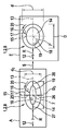
도 1에는 연료 분사 시스템을 위한 관형 본체(2)를 포함한 구성요소(1)가 도시되어 있다. 이 경우, 구성요소(1)는 특히 고압 연료 분사 시스템용으로 사용될 수 있다. 변형된 구성의 경우, 관형 본체(2)는 부분적으로만 관형으로 형성될 수 있다. 특히 관형 본체(2)는 그 단부들(3, 4) 중 하나에서 폐쇄될 수 있다. 구성요소(1)는 특히 연료 라인(1)일 수 있으며, 이 경우 단부들(3, 4)은 개방되어 있다. 그러나 구성요소(1)가 연료 분배기(1)일 수도 있거나 또는 연료 분사 시스템용 다른 구성요소(1)일 수 있다.Figure 1 shows a
관형 본체(2)는 관형 섹션(5)을 포함하며, 이 관형 섹션 상에 길이 방향 굽힘부(6)가 형성된다.The tubular body 2 comprises a tubular section 5 on which a longitudinal bend 6 is formed.
초기 상태에서 관형 본체(2)는 직선으로 연장될 수 있으며, 이 경우 길이 방향 라인(7)은 직선으로 연장된다. 길이 방향 굽힘부(6)가 형성된 후에, 만곡된 길이 방향 라인(7')이 달성된다. 길이 방향 라인(7')을 따라서 관형 본체(2)는, 길이 방향 라인(7')이 수직으로 관통하는 횡단면(8)을 포함한다. 여기서는 예시적으로 횡단면(8)이 표시되어 있다. 이 경우, 횡단면(8)은 관형 본체(2)의 길이 방향 굽힘부(6) 상에 배치된다.In the initial state, the tubular body 2 may extend straight, in which case the
이 실시예에서, 굽힘 각도(10)는 사전 설정되고 굽힘 후에 실현된다. 이로써, 만곡된 길이 방향 라인(7')의 두 다리부 사이에서 길이 방향 굽힘부(6)의 개방 각도(11)가 달성된다. 또한, 굽힘 반경(R)이 사전 설정된다. 예컨대, 길이 방향 굽힘부(6)를 제조하기 위해 환형 본체(2)가 굽혀지는 정도에 해당하는 굽힘 반경(R)을 갖는 실린더가 굽히기 위해 사용될 수 있다.In this embodiment, the bending
그러나 길이 방향 굽힘부(6)를 위해 반드시 단일 곡률이 사전 설정되지 않아도 된다. 길이 방향 굽힘부(6)의 곡률은 길이 방향 라인(7')을 따라서 가변될 수도 있다. 곡률 방향(12)은 길이 방향 라인(7')의 곡률의 경우에 따른 국소적 방향을 나타낸다. 이 경우, 곡률 방향(12)은 횡단면(8)의 평면에 위치하고 이 실시예에서는 길이 방향 라인(7')에 대해 수직으로 배향된다.However, a single curvature need not necessarily be preset for the longitudinal bend 6. The curvature of the longitudinal bend 6 may vary along the longitudinal line 7 '. The
따라서, 곡률 방향(12)은 상기 실시예에서 횡단면(8)의 축(13) 상에 위치한다. 상기 실시예에서 횡단면(8)은 축(13)을 따라 최대 외부 치수(D)를 갖는다.Thus, the direction of
도 2에는, 본 발명을 설명하기 위해 가능한 구성에 따라 길이 방향 굽힘부(6) 상에서 도 1에 도시된 구성요소(1)의 관형 본체(2)의 횡단면(8)이 도시되어 있다. 관형 횡단면(2)은 내부 챔버(14)를 포함하며, 이 내부 챔버를 통해 예컨대 연료가 길이 방향 라인(7')을 따라 안내될 수 있다. 최대 외부 치수(D)가 위치하는 축(13), 및 최소 외부 치수(d)가 위치하는 축(15)은 여기서는 길이 방향 라인(7') 상에서 교차된다. 또한, 외부 치수들(d, D)이 위치하는 두 축(13, 15)은 이 실시예에서 서로 수직으로 배향된다.Figure 2 shows a
타원도(x)는 여기서 백분율 값으로서 고려된다. 이 경우 타원도(x)의 계산은 도면에 표시된 The ellipticity (x) is considered here as a percentage value. In this case, the calculation of the ellipticity (x)
식 (1)에 따라According to equation (1)
분수 값으로부터 얻어진다. 상기 분수값의 피제수(dividend)는 최대 외부 치수(D)와 최소 외부 치수(d) 간의 차이의 절댓값과 곱셈 계수 2로부터 얻어진다. 제수(divisor)는 최대 외부 치수(D)와 최소 외부 치수(d)의 합으로부터 얻어진다. 타원도(x)가 여기서 백분율 값으로서 고려되는 것을 설명하기 위해, 상기 분수값은 여전히 식 (1)에 나타나는 것처럼 100%로 곱셈될 수 있다.Lt; / RTI > The dividend of the fractional value is obtained from the multiplication factor 2 and the absolute value of the difference between the maximum external dimension D and the minimum external dimension d. The divisor is obtained from the sum of the maximum external dimension (D) and the minimum external dimension (d). To illustrate that the ellipticity (x) is now considered as a percentage value, the fractional value can still be multiplied by 100% as shown in equation (1).
원형 외부 윤곽의 특수한 경우에, 최대 외부 치수(D)는 최소 외부 치수(d)와 동일하며, 그럼으로써 타원도(x)는 소멸된다.In the particular case of a circular outer contour, the maximum external dimension D is equal to the minimum external dimension d, so that the ellipticity x is extinguished.
도 3에는, 공정 시퀀스가 본 발명의 설명을 위해 개략도로 도시되어 있다. 여기서는, 간소화를 위해, 초기 상태(A)와 최종 상태(E)가 도시되어 있다. 연료 분사 시스템의 구성요소(1)의 제조 방법의 공정 단계(S)는, 본체(2)의 관형 섹션(5)이 길이 방향 굽힘부(6)를 형성하기 위해 관형 섹션(5)의 길이 방향 라인(7)을 따라서 굽혀지는 것인 적어도 하나의 단계를 포함한다.In Figure 3, a process sequence is shown schematically for purposes of describing the present invention. Here, for the sake of simplicity, an initial state A and a final state E are shown. The process step S of the method of manufacturing the
또한, 구성요소(1)의 제조 방법은, 길이 방향 굽힘부(6)의 형성 전 초기 상태(A)에 관련된다. 초기 상태(A)에서, 관형 본체(2)는 예컨대 도 1에 도시된 길이 방향 라인(7)을 따라서 연장될 수 있다. 굽힘 반경(R) 및 굽힘 각도(10) 또는 개방 각도(11)는 공정 단계(S) 전에 이미 결정된다. 다른 파라미터는, 여기에서 마찬가지로 결정되며 경계 조건인, 소정 재료 사용량이다. 상대적으로 더 많은 재료 사용량은 상대적으로 더 높은 강도 및 그에 따라 추가 영향을 가능하게 한다. 그러나 하기 설명에서, 재료 사용량은 이미 결정된 것으로서 가정된다.The manufacturing method of the
횡단면(8)은 이 실시예에서 타원형 기본 형태에서 전개된다. 예시적으로 표시된 벽 두께(16)는 원주에 걸쳐서 가변된다. 또한, 초기의 최대 외부 치수(D0) 및 초기의 최소 외부 치수(d0)는 모델링된다. 횡단면의 타원형 초기 형태는 예컨대 타원 외부 윤곽(17)에 의해 한정될 수 있다. 내부 챔버(14)를 한정하는 벽부(18)는 타원 내부 윤곽(19)에 의해 모델링될 수 있다. 이 경우, 추가로 길이 방향 라인(7)을 따라서 횡단면(8)의 변동이 가능하다. 특히 관형 본체(2)는 길이 방향 굽힘부(6)의 외부에서 중공 원통형으로 형성될 수 있다.The
모델 계산에 의해 및/또는 실험에 의해, 특히 초기 최대 외부 치수(D0), 초기 최소 외부 치수(d0), 및 원주방향(20)에서 벽 두께(16)의 변동은, 최종 상태(E)에서 소정 구성 및 특히 감소된 타원도(x) 및/또는 특정 값에 의해 제한되는 타원도(x)가 달성되도록 결정될 수 있다.Variations of the
이를 위해, 상기 실시예의 경우, 초기 상태(A)에서, 초기 최대 외부 치수(D0)가 위치하고 공정 단계(S) 후에는 최대 외부 치수가(D)가 위치하는 축(13)은 곡률 방향(12)을 따라서 배향된다. 초기 최소 외부 치수(d0)가 위치하고 공정 단계(S) 후에는 최소 외부 치수(d)가 위치하는 축(15)은 여기서 곡률 방향(12)을 대해 수직으로, 또는 축(13)에 대해 수직으로 사전 설정된다.To this end, in the case of the above embodiment, in the initial state A, the
또한, 원주에 걸쳐서, 다시 말하면 원주방향(20)으로 벽 두께(16)의 변동이 실현된다. 이 경우, 벽 두께(16)의 연속적인 변동이 실현된다. 여기서 연속적이란 원주방향(20)으로 고려할 때 벽 두께(16)의 갑작스런 변화가 실현되지 않는다는 것을 의미한다. 원주에 걸친 벽 두께(16)의 균일한 변화는 피크 응력을 방지한다.Also, a variation in the
또한, 축(15) 상에서 서로 대향하며, 여기서는 서로 동일한 2개의 최대 벽 두께(25, 26)가 달성된다. 또한, 축(13) 상에서는 서로 대향하는 2개의 최소 벽 두께(27, 28)가 달성된다.Again, two maximum wall thicknesses 25, 26, which are mutually opposite, are achieved on
이런 방식으로, 재료 사용량이 정해진 경우, 공정 단계(S) 후에 구성요소(1)의 최적화된 강도가 달성될 수 있다. 이 경우, 상기 실시예에서, 최종 상태(E)에서 적어도 거의 소멸하는 타원도(x)가 달성된다. 재료 사용량은 구성요소(1)의 부품 중량에 직접 영향을 미치기 때문에, 상기 방법은, 소정 강도와 관련하여 부품 중량의 최적화가 최대한 적은 재료 사용량에 의해 수행된다는 식으로도 볼 수 있다. 이런 고려에서 공정 파라미터인 재료 사용량은, 최적화된 기하구조의 경우 최종 상태(E)에서 바로 필요한 강도가 달성될 때까지 감소한다.In this way, when the amount of material used is determined, the optimized strength of the
또한, 상대적으로 더 얇은 벽 두께(16)는 상대적으로 더 높은 유연성을 가능하게 하며, 그럼으로써 이와 관련하여서도 최적화가 가능하다. 이 경우, 일반적으로 상대적으로 더 얇은 벽 두께(16)는 공정 단계(S) 후에 상대적으로 더 큰 타원도(x)로 이어진다. 그러므로 다른 벽 두께들(16), 특히 상대적으로 더 얇은 벽 두께들(16)에 의해, 예컨대 원주에 걸친 벽 두께(16)의 변동 및 초기 외부 치수들(d0, D0)에서 구분되는 다른 초기 기하구조들이 필요할 수도 있다.In addition, the relatively
따라서, 관형 본체(2)의 강도 및 내구성은 상이한 방식으로 영향을 받을 수 있다. 국소적으로 제한되거나 또는 전체 길이 방향 라인(7)을 따라 수행되는 횡단면(8)의 변형에 의해, 초기 상태(A)에서, 특히, 강도를 향상시키기 위해 초기 상태(A)에서의 타원도(x)가 공정 단계(S)에 걸쳐서 수행되는 변동 및 최종 상태(E)에서 달성된 타원도(x)에 상반되는 횡단면(8)이 실현될 수 있다.Thus, the strength and durability of the tubular body 2 can be influenced in different ways. By virtue of the deformation of the
따라서, 상응하는 굽힘의 결과로 중공 원통형 몸체를 형성하는, 최종 상태(E)에서의 타원도(x)와 관련하여, 타원도(x)의 감소가 달성될 수 있다. 또한, 8% 미만인, 바람직하게는 5% 미만인 최종 상태(E)에서의 타원도(x)가 달성될 수 있다. 실질적인 장점들은, 특히 90°보다 큰 굽힘 각도(10) 및/또는 20㎜ 미만인 굽힘 반경(R) 또는 곡률 반경들에서 달성된다.Thus, in relation to the ellipticity (x) in the final state (E), which forms the hollow cylindrical body as a result of the corresponding bending, a reduction of the ellipticity (x) can be achieved. Also, an ellipticity (x) in the final state (E) of less than 8%, preferably less than 5%, can be achieved. The substantial advantages are achieved, in particular at bending radii (R) greater than 90 degrees and / or bending radii (R) less than 20 mm.
도 4에는, 본 발명의 또 다른 가능한 구성에 따라, 도 1에 도시된 구성요소(1)의 관형 본체(2)의 횡단면(8)이 도시되어 있다. 여기서는, 도 3에 도시된 공정 시퀀스에 따라 사전 설정되는 초기 상태(A)에서의 구성이 도시되어 있다. 이 실시예의 경우, 횡단면(8)은 직사각형 중공 프로파일을 기반으로 모델링된다. 이 경우, 외부 윤곽(17) 상에 뿐만 아니라 내부 윤곽(19) 상에도 에지 라운딩부들(30, 31)이 제공되며, 이들 에지 라운딩부 중 에지 라운딩부들(30, 31)이 도 4에 예시적으로 도시되어 있다. 이로써, 원주방향(20)으로 벽 두께(16)의 연속적인 변동이 달성된다. 이 경우, 벽 두께(16)는 길이 방향 라인(7)과 관련하여 고려된다. 이 실시예에서도, 초기 상태(A)에서 최대 벽 두께들(25, 26)은 초기 최소 외부 치수(d0)가 위치하는 축(15) 상에서 사전 설정된다. 최소 벽 두께들(27, 28)은 곡률 방향(12)을 따라 연장되는 축(32) 상에 위치한다. 초기 최대 외부 치수(D0)가 위치하는 축(13)은, 이 실시예의 경우, 초기 최소 외부 치수(d0)가 위치하는 축(15)에 대해 수직을 이루지 않는다. 이런 경우, 이에 상응하는 사항은 최종 상태(E)에서도 발생한다.Figure 4 shows a
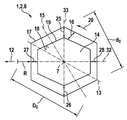
도 5에는, 또 다른 가능한 구성에 따라, 도 1에 도시된 구성요소(1)의 관형 본체(2)의 횡단면(8)이 도시되어 있다. 이 실시예의 경우, 횡단면(8)은 6각형 중공체 프로파일로부터 형성된다. 이 경우, 6각형 구조는 외부 윤곽(17)에 대해서뿐만 아니라 내부 윤곽(19)에 대해서도 사전 설정된다. 이 경우, 최대 벽 두께들(25, 26)은, 곡률 방향(12)에 대해 수직인 축(33) 상에서 달성된다. 최소 벽 두께들(27, 28)은, 곡률 방향(12)을 따라서 배향되는 축(32) 상에서 달성된다. 이 경우, 초기 최소 외부 치수(d0)가 위치하는 축(15) 및 초기 최대 외부 치수(Do)가 위치하는 축(13)은 축(32) 및 축(33)과 각각 일치하지 않는다. 그러나 축들(32, 33)은 서로 수직으로 배향된다.5 shows a
관형 본체(2)를 위한 재료로서는, 탄소강 또는 스테인리스 강과 같은 강재들뿐만 아니라 다른 소재들도 사용될 수 있다. 예컨대 다른 금속들도 적합하다. 각각의 적용 사례에서, 플라스틱을 기반으로 하는 재료들 또는 적합한 복합 재료들도 사용될 수 있다.As the material for the tubular body 2, other materials as well as steel materials such as carbon steel or stainless steel can be used. Other metals, for example, are also suitable. In each application, plastic-based materials or suitable composite materials may be used.
본 발명은 설명된 실시예들로 제한되지 않는다.The present invention is not limited to the embodiments described.
1: 구성요소
2: 관형 본체
3: 단부
4: 단부
5: 관형 섹션
6: 길이 방향 굽힘부
7, 7': 길이 방향 라인, 길이방향 축
8: 횡단면
10: 굽힘 각도
11: 개방 반경
12: 곡률 방향
13: 축
14: 내부 챔버
15: 축
16: 벽 두께
17: 타원 외부 윤곽
18: 벽부
19: 타원 내부 윤곽
20: 원주방향
25, 26: 최대 벽 두께
27, 28: 최소 벽 두께
32, 33: 축
A: 초기 상태
D: 최대 외부 치수
d: 최소 외부 치수
E: 최종 상태
R: 굽힘 반경
S: 공정 단계1: Components
2: tubular body
3: end
4: end
5: tubular section
6: longitudinal bending portion
7, 7 ': longitudinal line, longitudinal axis
8: Cross section
10: Bending angle
11: Open radius
12: Direction of curvature
13: Axis
14: Inner chamber
15: Axis
16: Wall thickness
17: contour outside the ellipse
18: wall portion
19: Outline of the ellipse
20: circumferential direction
25, 26: maximum wall thickness
27, 28: minimum wall thickness
32, 33: Axis
A: Initial state
D: Maximum external dimension
d: Minimum external dimension
E: Final state
R: Bending radius
S: process step
Claims (10)
상기 본체(2)는 적어도 하나의 관형 섹션(5)을 포함하고,
상기 관형 섹션(5)은, 상기 관형 섹션(5)의 횡단면(8)을 수직으로 관통하는 길이 방향 라인(7')을 포함하고,
상기 관형 섹션(5)은 상기 길이 방향 라인(7')을 따라서 길이 방향 굽힘부(6)를 포함하고,
상기 본체(2)는, 길이 방향 굽힘부(6) 상에서 상기 관형 섹션(5)의 상기 횡단면(8)의 타원도(x)가 감소하고 및/또는 8% 미만 이도록, 적어도 상기 관형 섹션(5)의 상기 길이 방향 굽힘부(6) 상에 형성되는 것을 특징으로 하는 연료 분사 시스템용 구성요소.A component (1) for a fuel injection system, in particular a high-pressure fuel injection system, comprising a body (2) formed at least partly in a tubular form,
The body (2) comprises at least one tubular section (5)
The tubular section (5) comprises a longitudinal line (7 ') passing vertically through the cross-section (8) of the tubular section (5)
The tubular section (5) comprises a longitudinal bend (6) along the longitudinal line (7 '),
Characterized in that the body (2) comprises at least a tubular section (5) such that on the longitudinal bend (6) the ellipticity (x) of the cross section (8) of the tubular section (5) decreases and / Is formed on the longitudinal bend (6) of the fuel injection system.
관형 섹션(5)의 횡단면(8)을 수직으로 관통하는, 상기 관형 섹션(5)의 길이 방향 라인(7)을 따르는 상기 본체(2)의 적어도 하나의 관형 섹션(5)이 길이 방향 굽힘부(6)를 형성하기 위해 굽혀지고, 상기 관형 섹션(5)은, 상기 길이 방향 굽힘부(6)의 형성 전에, 형성 대상 길이 방향 굽힘부(6) 상에서 상기 관형 섹션(5)의 횡단면(8) 각각에 대한 최대 벽 두께들(25, 26)이 상기 길이 방향 굽힘부(6)의 해당 위치의 곡률 방향(12)에 대해 수직으로 배향되는 축(15, 33) 상에 적어도 대략 위치하며 최소 벽 두께들(27, 28)이 상기 길이 방향 굽힘부(6)의 해당 위치의 곡률 방향(12)을 따라서 배향되는 축(13, 32) 상에 적어도 대략 위치하도록, 및/또는 상기 형성 대상 길이 방향 굽힘부(6) 상에서 상기 관형 섹션(5)의 횡단면(8) 각각에 대한 초기 최소 외부 치수(d0)가 상기 길이 방향 굽힘부(6)의 해당 위치의 곡률 방향(12)에 대해 적어도 거의 수직으로 배향되는 축(15) 상에 존재하며 및/또는 초기 최대 외부 치수(D0)가 적어도 거의 상기 길이 방향 굽힘부(6)의 해당 위치의 곡률 방향(12)을 따라서 배향되는 축(13) 상에 존재하는 조건의 타원도(x)가 사전 설정되도록, 형성되는 것을 특징으로 하는 연료 분사 시스템의 구성요소의 제조 방법.A method of manufacturing a fuel injection system, in particular a component (1) of a high pressure fuel injection system, characterized in that a body (2) at least partly tubular is formed on the component (1) In this case,
Characterized in that at least one tubular section (5) of the body (2) along the longitudinal line (7) of the tubular section (5) passing vertically through the transverse section (8) of the tubular section (5) (8) of the tubular section (5) on the longitudinal bend (6) to be formed before the formation of the longitudinal bend (6), wherein the tubular section (5) ) Are located at least approximately on axes (15, 33) oriented perpendicular to the curvature direction (12) of the corresponding position of the longitudinal bend (6) So that the wall thicknesses 27 and 28 are located at least approximately on the axes 13 and 32 oriented along the curvature direction 12 of the corresponding position of the longitudinal bend 6 and / the cross-section (8) initially the minimum outer dimension (d 0) for each of the tubular section (5) in the longitudinal direction on the direction of the bending portion 6 heeled Section (6) that point in the curvature direction on at least almost for 12 present on a shaft 15 which is vertically aligned with, and / or the initial maximum outer dimension of (D 0), the direction of the bending section (6 at least almost the length (X) of the condition existing on the axis (13) oriented along the direction of curvature (12) of the corresponding position of the fuel injection system (12) is preset.
Applications Claiming Priority (3)
| Application Number | Priority Date | Filing Date | Title |
|---|---|---|---|
| DE102015226807.1A DE102015226807A1 (en) | 2015-12-29 | 2015-12-29 | Component for fuel injection system and method for manufacturing a component of a fuel injection system |
| DE102015226807.1 | 2015-12-29 | ||
| PCT/EP2016/079580 WO2017114636A1 (en) | 2015-12-29 | 2016-12-02 | Component for a fuel injection system, and method for producing a component of a fuel injection system |
Publications (1)
| Publication Number | Publication Date |
|---|---|
| KR20180098563A true KR20180098563A (en) | 2018-09-04 |
Family
ID=57485475
Family Applications (1)
| Application Number | Title | Priority Date | Filing Date |
|---|---|---|---|
| KR1020187018516A Withdrawn KR20180098563A (en) | 2015-12-29 | 2016-12-02 | COMPONENTS FOR FUEL INJECTION SYSTEM, AND METHOD FOR MANUFACTURING COMPONENTS OF FUEL INJECTION SYSTEM |
Country Status (8)
| Country | Link |
|---|---|
| US (1) | US11365709B2 (en) |
| EP (1) | EP3356116B1 (en) |
| KR (1) | KR20180098563A (en) |
| CN (1) | CN108430737B (en) |
| BR (1) | BR112018012708B8 (en) |
| DE (1) | DE102015226807A1 (en) |
| PL (1) | PL3356116T3 (en) |
| WO (1) | WO2017114636A1 (en) |
Families Citing this family (1)
| Publication number | Priority date | Publication date | Assignee | Title |
|---|---|---|---|---|
| CN115916100A (en) * | 2020-04-24 | 2023-04-04 | 福尔顿控股公司 | Tube for pinch valve, pinch valve and powder gas injection device with such tube and method for producing such tube for pinch valve |
Family Cites Families (30)
| Publication number | Priority date | Publication date | Assignee | Title |
|---|---|---|---|---|
| US2774384A (en) * | 1953-09-15 | 1956-12-18 | Griscom Russell Co | Heat exchanger u-tubes |
| US2724891A (en) * | 1953-11-10 | 1955-11-29 | Combustion Eng | Method of decreasing radius of curvature in return bend |
| US2983995A (en) * | 1955-04-19 | 1961-05-16 | Gresse Andre | Bending process |
| NL165667C (en) * | 1976-09-03 | 1981-05-15 | Cojafex | METHOD AND APPARATUS FOR CONTINUOUSLY BENDING OF LONG-LIKE OBJECTS SUCH AS TUBES. |
| JPS6179619A (en) * | 1984-09-28 | 1986-04-23 | Shoketsu Kinzoku Kogyo Co Ltd | Manufacture of synthetic resin coiled tube |
| GB2172203B (en) * | 1985-03-14 | 1988-11-09 | Univ Manchester | A urethral catheter |
| GB8619759D0 (en) * | 1986-08-13 | 1986-09-24 | Ferguson J M | Tube bends |
| US5339868A (en) * | 1987-01-07 | 1994-08-23 | Nippon Steel Corporation | Bent pipe having sectional form of high strength |
| US5094096A (en) * | 1989-06-14 | 1992-03-10 | Chromcraft Furniture Corp. | Method of bending |
| US5339670A (en) * | 1993-05-24 | 1994-08-23 | Anthony Granelli | Apparatus and method for bending tubing |
| US6098668A (en) * | 1998-01-06 | 2000-08-08 | Navistar International Transportation Corp | Integral tube/nut stopper for engine fuel line tube |
| US6287508B1 (en) * | 1999-02-26 | 2001-09-11 | Dayco Products, Inc. | Method for manufacturing curved thermoplastic tubes |
| US6309588B1 (en) * | 1999-06-04 | 2001-10-30 | Dana Corporation | Process and apparatus for bending thin-wall plastic tubing |
| DE10117968A1 (en) | 2001-01-19 | 2002-08-01 | Siemens Ag | Propellant line for a suction jet pump and two methods for producing the propellant line |
| JP3887542B2 (en) * | 2001-02-26 | 2007-02-28 | 新日本製鐵株式会社 | Structural members for automobiles |
| DE10123234A1 (en) | 2001-05-12 | 2002-11-28 | Bosch Gmbh Robert | High pressure fuel accumulator for a common rail fuel injection system of an internal combustion engine comprises an accumulator chamber and a base body having a cylindrical, elliptical or polygonal cross-section |
| US6675835B2 (en) * | 2001-07-10 | 2004-01-13 | Systec, Inc. | Elliptical tubing in degassing and pulsation dampener application |
| JP3943390B2 (en) * | 2001-12-27 | 2007-07-11 | テルモ株式会社 | Metal tubular body and manufacturing method thereof |
| RU2209698C1 (en) | 2002-01-03 | 2003-08-10 | Федеральное государственное унитарное предприятие "Научно-исследовательский институт "Гермес" | Method for bending thin-wall tubes |
| US6910505B2 (en) * | 2002-04-12 | 2005-06-28 | Micasa Trading Corporation | Coiled hose |
| JP5013912B2 (en) * | 2006-03-28 | 2012-08-29 | 東海ゴム工業株式会社 | Resin composite hose and manufacturing method thereof |
| US8127799B2 (en) * | 2007-12-18 | 2012-03-06 | Robert Cortez | Aircraft fluid transport line repair kit and method of use thereof |
| CA2653137C (en) * | 2009-02-09 | 2016-01-12 | Manfred A. A. Lupke | Non-circular pipe profile |
| GB0903554D0 (en) * | 2009-03-02 | 2009-04-08 | Wheeler Russell | A fluid transfer pipe and fluid transfer apparatus and a fluid attenuator and attenuator apparatus |
| US20110163179A1 (en) * | 2010-01-06 | 2011-07-07 | Erik Lipson | Drinking straw with opaque, imprinted side |
| JP5228069B2 (en) * | 2011-01-21 | 2013-07-03 | 株式会社小松製作所 | Air pipe and supercharger |
| DE102011105279A1 (en) * | 2011-06-10 | 2012-12-13 | Pfw Aerospace Ag | Method for bending thermoplastic pipes |
| US8931521B2 (en) * | 2011-06-10 | 2015-01-13 | Pfw Aerospace Ag | Bent thermoplastic pipe |
| DE102011086209A1 (en) * | 2011-11-11 | 2013-05-16 | Robert Bosch Gmbh | fuel distributor |
| DE102012012039A1 (en) | 2012-06-19 | 2013-12-19 | Man Truck & Bus Ag | Intake system for internal combustion engines |
-
2015
- 2015-12-29 DE DE102015226807.1A patent/DE102015226807A1/en not_active Withdrawn
-
2016
- 2016-12-02 BR BR112018012708A patent/BR112018012708B8/en not_active IP Right Cessation
- 2016-12-02 CN CN201680077195.7A patent/CN108430737B/en not_active Expired - Fee Related
- 2016-12-02 EP EP16806054.9A patent/EP3356116B1/en active Active
- 2016-12-02 WO PCT/EP2016/079580 patent/WO2017114636A1/en not_active Ceased
- 2016-12-02 US US16/065,975 patent/US11365709B2/en active Active
- 2016-12-02 PL PL16806054.9T patent/PL3356116T3/en unknown
- 2016-12-02 KR KR1020187018516A patent/KR20180098563A/en not_active Withdrawn
Also Published As
| Publication number | Publication date |
|---|---|
| DE102015226807A1 (en) | 2017-06-29 |
| WO2017114636A1 (en) | 2017-07-06 |
| EP3356116A1 (en) | 2018-08-08 |
| BR112018012708A2 (en) | 2019-04-24 |
| CN108430737B (en) | 2021-06-08 |
| BR112018012708B8 (en) | 2022-12-13 |
| EP3356116B1 (en) | 2020-09-30 |
| CN108430737A (en) | 2018-08-21 |
| BR112018012708B1 (en) | 2022-03-22 |
| US20190017479A1 (en) | 2019-01-17 |
| PL3356116T3 (en) | 2021-02-22 |
| US11365709B2 (en) | 2022-06-21 |
Similar Documents
| Publication | Publication Date | Title |
|---|---|---|
| EP1811165A2 (en) | Common rail having orifice | |
| KR20190012172A (en) | Method for manufacturing a high-pressure accumulator and a high-pressure accumulator | |
| JP2002168158A (en) | High-pressure fuel accumulator for fuel injection system for internal combustion engines | |
| JP2003510491A (en) | Fuel high pressure accumulator | |
| JP5325306B2 (en) | Fuel injection system | |
| KR20180098563A (en) | COMPONENTS FOR FUEL INJECTION SYSTEM, AND METHOD FOR MANUFACTURING COMPONENTS OF FUEL INJECTION SYSTEM | |
| CN107429862B (en) | Connection components for constructing hydraulic connections | |
| JP6382665B2 (en) | Delivery pipe for gasoline | |
| US6796512B2 (en) | High-pressure-proof injector body | |
| US20190010907A1 (en) | Component of a hydraulic device, in particular of a fuel injection system for internal combustion engines | |
| JP5040928B2 (en) | Accumulator and method for manufacturing the same | |
| GB2537642A (en) | Supply rail body | |
| US20100116251A1 (en) | Area of intersection between a high-pressure chamber and a high-pressure duct | |
| JP6429087B2 (en) | Common rail | |
| EP3604787B1 (en) | Fuel rail for a fuel injection system and method of manufacturing such a fuel rail | |
| JP2007127096A (en) | High pressure fluid accumulator | |
| KR20230084263A (en) | Threaded steel pipe and its manufacturing method | |
| JP2014196730A (en) | Fuel supply pipe | |
| JP2006515396A (en) | Method of machining a workpiece for a fuel high pressure accumulator and a workpiece for using this method | |
| JP6443683B2 (en) | Manufacturing method of common rail | |
| JP6429088B2 (en) | Common rail | |
| US11725617B2 (en) | Fluid distributor for an injection system, in particular a fuel distributor rail for a fuel injection system for mixture-compressing, spark-ignited internal combustion engines | |
| KR20040049786A (en) | A pressure reservoir for a common rail system | |
| JP2022118756A (en) | Direct injection engine high-pressure fuel delivery pipe assembly | |
| US20230008682A1 (en) | Fluid distributor for an injection system, in particular a fuel distributor rail for a fuel injection system for mixture-compressing spark-ignition internal combustion engines |
Legal Events
| Date | Code | Title | Description |
|---|---|---|---|
| PA0105 | International application |
Patent event date: 20180628 Patent event code: PA01051R01D Comment text: International Patent Application |
|
| PG1501 | Laying open of application | ||
| A201 | Request for examination | ||
| PA0201 | Request for examination |
Patent event code: PA02012R01D Patent event date: 20211104 Comment text: Request for Examination of Application |
|
| PC1202 | Submission of document of withdrawal before decision of registration |
Comment text: [Withdrawal of Procedure relating to Patent, etc.] Withdrawal (Abandonment) Patent event code: PC12021R01D Patent event date: 20230227 |
|
| WITB | Written withdrawal of application |