JP3887542B2 - Structural members for automobiles - Google Patents
Structural members for automobiles Download PDFInfo
- Publication number
- JP3887542B2 JP3887542B2 JP2001049800A JP2001049800A JP3887542B2 JP 3887542 B2 JP3887542 B2 JP 3887542B2 JP 2001049800 A JP2001049800 A JP 2001049800A JP 2001049800 A JP2001049800 A JP 2001049800A JP 3887542 B2 JP3887542 B2 JP 3887542B2
- Authority
- JP
- Japan
- Prior art keywords
- cross
- structural member
- door
- sectional shape
- longitudinal direction
- Prior art date
- Legal status (The legal status is an assumption and is not a legal conclusion. Google has not performed a legal analysis and makes no representation as to the accuracy of the status listed.)
- Expired - Fee Related
Links
Images


Classifications
-
- B—PERFORMING OPERATIONS; TRANSPORTING
- B60—VEHICLES IN GENERAL
- B60J—WINDOWS, WINDSCREENS, NON-FIXED ROOFS, DOORS, OR SIMILAR DEVICES FOR VEHICLES; REMOVABLE EXTERNAL PROTECTIVE COVERINGS SPECIALLY ADAPTED FOR VEHICLES
- B60J5/00—Doors
-
- B—PERFORMING OPERATIONS; TRANSPORTING
- B60—VEHICLES IN GENERAL
- B60J—WINDOWS, WINDSCREENS, NON-FIXED ROOFS, DOORS, OR SIMILAR DEVICES FOR VEHICLES; REMOVABLE EXTERNAL PROTECTIVE COVERINGS SPECIALLY ADAPTED FOR VEHICLES
- B60J5/00—Doors
- B60J5/04—Doors arranged at the vehicle sides
- B60J5/042—Reinforcement elements
- B60J5/0422—Elongated type elements, e.g. beams, cables, belts or wires
- B60J5/0438—Elongated type elements, e.g. beams, cables, belts or wires characterised by the type of elongated elements
- B60J5/0443—Beams
- B60J5/0444—Beams characterised by a special cross section
-
- B—PERFORMING OPERATIONS; TRANSPORTING
- B60—VEHICLES IN GENERAL
- B60R—VEHICLES, VEHICLE FITTINGS, OR VEHICLE PARTS, NOT OTHERWISE PROVIDED FOR
- B60R19/00—Wheel guards; Radiator guards, e.g. grilles; Obstruction removers; Fittings damping bouncing force in collisions
- B60R19/02—Bumpers, i.e. impact receiving or absorbing members for protecting vehicles or fending off blows from other vehicles or objects
- B60R19/18—Bumpers, i.e. impact receiving or absorbing members for protecting vehicles or fending off blows from other vehicles or objects characterised by the cross-section; Means within the bumper to absorb impact
-
- B—PERFORMING OPERATIONS; TRANSPORTING
- B62—LAND VEHICLES FOR TRAVELLING OTHERWISE THAN ON RAILS
- B62D—MOTOR VEHICLES; TRAILERS
- B62D21/00—Understructures, i.e. chassis frame on which a vehicle body may be mounted
- B62D21/15—Understructures, i.e. chassis frame on which a vehicle body may be mounted having impact absorbing means, e.g. a frame designed to permanently or temporarily change shape or dimension upon impact with another body
-
- B—PERFORMING OPERATIONS; TRANSPORTING
- B60—VEHICLES IN GENERAL
- B60R—VEHICLES, VEHICLE FITTINGS, OR VEHICLE PARTS, NOT OTHERWISE PROVIDED FOR
- B60R19/00—Wheel guards; Radiator guards, e.g. grilles; Obstruction removers; Fittings damping bouncing force in collisions
- B60R19/02—Bumpers, i.e. impact receiving or absorbing members for protecting vehicles or fending off blows from other vehicles or objects
- B60R19/18—Bumpers, i.e. impact receiving or absorbing members for protecting vehicles or fending off blows from other vehicles or objects characterised by the cross-section; Means within the bumper to absorb impact
- B60R2019/1806—Structural beams therefor, e.g. shock-absorbing
- B60R2019/1813—Structural beams therefor, e.g. shock-absorbing made of metal
- B60R2019/1826—Structural beams therefor, e.g. shock-absorbing made of metal of high-tension steel
Abstract
Description
【0001】
【発明の属する技術分野】
本発明は、優れた曲げ強度と吸収エネルギー特性を発揮することができ、しかも軽量化も図ることができる自動車用構造部材(例えば、ドア補強部材であるドアインパクトプロテクション用ビーム、ピラー補強部材やバンパー補強部材)に関するものである。
【0002】
【従来の技術】
従来から、自動車の側面衝突時に運手者の安全を確保するために自動車用構造部材(例えばドア補強部材であるドアインパクトプロテクション)が広く使用されている。そして、このドアインパクトプロテクションとしては、衝突安全性を確保するとともに軽量化による低燃費化を図るために超高張力鋼管が採用されている。このような鋼管材料としては、引張強さが1400Mpa以上のものであって、その断面形状は真円のものが一般的であった。
【0003】
一方、自動車部品等の軽量化により低燃費を更に図る必要があり、ドアインパクトプロテクションもより軽いものが要求されているので可能な限り肉厚の薄いものが好ましい。しかしながら、ドアインパクトプロテクションは衝突時における安全性を確保するものであり、所定値以上の曲げ強度と吸収エネルギー特性を確保する必要があるが、従来の真円形状のものでは今以上に肉厚を薄くすることは困難であり、従って肉厚の面から軽量化を図ることはほぼ限界にきていた。
【0004】
【発明が解決しようとする課題】
本発明は上記のような従来の問題点を解決して、自動車衝突時、特に側面衝突時において、従来の円形断面の鋼管に比べほぼ同等あるいはそれ以上の高い曲げ強度と吸収エネルギー特性を有し、しかも従来のものよりも更に軽量化を達成することができる例えば、ドア補強部材であるドアインパクトプロテクション用ビーム、ピラー補強部材やバンパー補強部材等の自動車用構造部材を提供することを目的として完成されたものである。
【0005】
【課題を解決するための手段】
上記の課題を解決するためになされた本発明の自動車用構造部材は、引張強さが1400Mpa以上、伸び率が5%以上で断面形状が長方形に内接しかつ各コーナー部を円弧によって角取りした形状を基本とする閉断面構造の高張力鋼管で形成されており、側面衝突方向と一致するように車体に配置される長手方向側の最大寸法をa、これと直角方向の荷重受け面側の最大寸法をb、外周長さをL、肉厚をtとした場合に、断面形状が
【数2】

【0006】
また、断面形状の辺の少なくとも一箇所に直線部を有しているものを請求項2に係る発明とし、ドアに取り付けた場合にビーム断面形状において前記長手方向が側面衝突方向と一致し、この長手方向と直角方向が荷重受け面側となるように車体に配置してなるドアインパクトプロテクション用ビームに用いたものを請求項3に係る発明とする。
【0007】
【発明の実施の形態】
以下に、図面を参照しつつ本発明をドアインパクトプロテクション用ビームに用いた場合の好ましい実施の形態を示す。
本発明のドアインパクトプロテクション用ビームは、成分組成が例えば、重量%でC:0.24%、Si:0.25%、Mn:2.4%、Cr:0.5%、Mo:0.7%、Ti:0.03%、B:20ppm、残部はFeおよび不可避的元素からなる鋼帯を用いて成形された、引張強さが1400Mpa以上、伸び率が5%以上の断面形状が閉断面構造の高張力鋼管で形成されるものである。
そして、長手方向側の最大寸法をa、これと直角方向の荷重受け面側の最大寸法をb、外周長さをL、肉厚をtとした場合に、断面形状が
【数3】
なお、本発明のビーム断面形状は、長方形に内接しかつ各コーナー部を円弧によって角取りした形状を基本とするものであり、各コーナー部を円弧状とすることで衝撃荷重が加えられた場合、各コーナー部の過剰な応力集中により、極端な割れや座屈が発生するのを防止している。
以下に、上記の寸法を制限した理由につき説明する。
【0008】
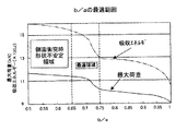
(1)b/aの限定条件について
図1は、同一断面積の鋼管の3点曲げテストをした場合の、最大荷重と吸収エネルギー量の曲げ特性を評価したグラフである。
なお、3点曲げテストの条件は、後述の実施例に示すとおりであり、表1にあるように、外周長さをL(100mm)、肉厚をt(1.6mm)を一定とし、長手方向側の最大寸法をa、これと直角方向の荷重受け面側の最大寸法をbを変えた場合の最大荷重と吸収エネルギー量を測定した。
b/aを円形(b/a=1)から徐々に小さくしていくと、最大荷重・吸収エネルギーとも増加し、b/a<≦0.75では、急激に大きくなる。更に、b/a<0.65でも曲げ特性は向上するが、長辺aが、短辺bに対し大きくなりすぎて形状的に不安定となり、側面衝突時においてビームの捩れ・回転が発生するため、ビーム本来の性能が発揮されず安全性上問題のある可能性がある。また、ドア内へ配置した場合、スペース制約上、配置できない場合がある。
従って、0.65≦b/a≦0.75の範囲が好ましい。
【0009】
(2)t/Lの限定条件について
有効な断面形状を決定するには、b/aの他に、板厚tと外周長さLの比t/Lが重要なパラメーターである。
図2は、b/aが上記範囲内におけるtとLとの関係を示した例である。
t/L<0.014の領域では、tに対しLが大きいため、座屈が派生しやすくなり、更に座屈後の割れも大きくなりやすい。一方、t/L>0.020の領域は、曲げ特性としては良好であるが、Lに対しtが大きいため重量増の方向になり、軽量化を目的としていることに反してくる。
また、実際のドアに取付ける場合は、0.014≦t/L≦0.020の範囲以外に、ドア内の取付けスペースからLが制約され、軽量化等の要求からtが制約される。更には、Lとtの充分な曲げ性能をもつ領域にある必要があり、Lとtの積L×t>K(Kは、ドアの要求性能から決まる定数)で囲まれた領域が最適領域となる(図2の斜線部分、但しK=140の場合)。
【0010】
(3)ドアへの配置について
本発明は、円形断面のように全方位性ではないために、ドア内への配置は、曲げ特性を最大限に発揮するように方向性をもたせる必要がある。即ち、ドアに取り付けた場合にビーム断面形状において長手方向が側面衝突方向と一致するように配置する必要がある。
【0011】
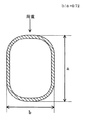
ビーム断面形状としては、長手方向と直角の方向の中立軸から、質量分布が離れた方が曲げ剛性が向上するため、例えば図4に示されるように、長手方向の2辺に直線部分のある小判形状や、図5〜図6に示されるように、長手方向の2辺とその直角方向の2辺に直線部分のあるほぼ長方形形状のものは、曲げ剛性を大きく向上させることができるため、好ましい。
【0012】
また、長手方向に直線部がある場合、曲げ剛性は向上するが座屈後に割れが大きくなる傾向にあり、この座屈による割れを軽減させるためには、図7に示されるように、長手方向を外側に凸の湾曲部をもつことが望ましい。
【0013】
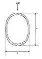
また、図8に示されるように、長手方向とその直角方向が滑らかな湾曲でつながっている楕円形状は、衝突による形状が不安定で、捩れ・曲がりが発生しやすい傾向にあるが、座屈がしにくく、かつ座屈による割れが非常に小さくなるのでビームに採用することができる。
本発明の自動車用構造部材は、前記のドアインパクトプロテクション用ビーム以外にも、ピラー補強部材やバンパー補強部材としても用いることができる。
【0014】
【実施例】
表1に示される寸法および各比率を有するビームを、スパン950mmで3点曲げ試験(速度2mm/s、押込み変位量200mm)を行ったところ、最大荷重および吸収エネルギーともに満足のいくものであった。一方、比較例として、従来タイプのφ31.8mm×t1.8mmの円形断面を有するものと、軽量化を図ったφ31.8mm×t1.6mmの円形断面を有するものの3点曲げ試験を同様にして行った。なお、実施例1,2,3は、それぞれ図4、図5、図6に相当するものである。
この結果からも明らかなように、本発明のビームは軽量化タイプであるφ31.8mm×t1.6mmの円形断面を有するものと同一重量でありながら、最大荷重および吸収エネルギーともにφ31.8mm×t1.8mmの円形断面を有するものと同等以上の性能を有するものであり、優れた形状特性を発揮できることが確認できた(図9)。
【0015】
【表1】
【発明の効果】
以上の説明からも明らかなように、本発明は自動車衝突時、特に側面衝突時において、従来の円形断面の鋼管に比べ、高い曲げ強度と吸収エネルギー特性をもつことにより、自動車用構造部材(例えば、ドア補強部材であるドアインパクトプロテクション用ビーム、ピラー補強部材やバンパー補強部材)の軽量化を可能とするものである。
よって本発明は従来の問題点を一掃した自動車用構造部材として、産業の発展に寄与するところは極めて大である。
【図面の簡単な説明】
【図1】φ31.8mm×t1.6mmの円形断面と同一重量で、aとbの比を様々に変えた四辺形形状のビームを、スパン950mmで3点曲げ試験をした、b/aと最大荷重及び吸収エネルギーの関係を表した図である。
【図2】肉厚tと外周長さLの関係の例を示す図である。
【図3】スパン950mmで3点曲げ試験をした場合の変位と荷重の関係を示す図である。
【図4】本発明の実施の形態を示す断面図である。
【図5】その他の実施の形態を示す断面図である。
【図6】その他の実施の形態を示す断面図である。
【図7】その他の実施の形態を示す断面図である。
【図8】その他の実施の形態を示す断面図である。
【図9】実施例および比較例の3点曲げ試験をした結果を示すグラフである。[0001]
BACKGROUND OF THE INVENTION
INDUSTRIAL APPLICABILITY The present invention can provide an automotive structural member that can exhibit excellent bending strength and absorbed energy characteristics and can be reduced in weight (for example, a door impact protection beam, a pillar reinforcing member, and a bumper that are door reinforcing members). (Reinforcing member).
[0002]
[Prior art]
2. Description of the Related Art Conventionally, automobile structural members (for example, door impact protection, which is a door reinforcing member) have been widely used in order to ensure the safety of a driver during a side collision of an automobile. And as this door impact protection, in order to ensure collision safety and reduce fuel consumption by reducing the weight, an ultra-high strength steel pipe is adopted. Such a steel pipe material generally has a tensile strength of 1400 MPa or more and a cross-sectional shape of a perfect circle.
[0003]
On the other hand, it is necessary to further reduce fuel consumption by reducing the weight of automobile parts and the like, and lighter door impact protection is required. However, door impact protection is to ensure safety in the event of a collision, and it is necessary to ensure bending strength and absorbed energy characteristics that are greater than the specified value. It is difficult to reduce the thickness, and therefore it has been almost the limit to reduce the weight in terms of thickness.
[0004]
[Problems to be solved by the invention]
The present invention solves the conventional problems as described above, and has high bending strength and absorbed energy characteristics that are substantially equal to or higher than those of conventional steel pipes having a circular cross section in a car crash, particularly in a side crash. In addition, it is possible to achieve further weight reduction than conventional ones. For example, it is completed for the purpose of providing automotive structural members such as door impact protection beams, pillar reinforcing members and bumper reinforcing members which are door reinforcing members. It has been done.
[0005]
[Means for Solving the Problems]
The structural member for automobiles of the present invention, which has been made to solve the above problems, has a tensile strength of 1400 Mpa or more, an elongation of 5% or more, a cross-sectional shape inscribed in a rectangle, and each corner portion is rounded by an arc. It is formed of a high-strength steel pipe with a closed cross-section structure based on the shape, and the maximum dimension on the longitudinal side arranged on the vehicle body so as to coincide with the side collision direction is a, on the load receiving surface side perpendicular to this When the maximum dimension is b, the outer peripheral length is L, and the wall thickness is t, the cross-sectional shape is
[0006]
Further, the invention according to
[0007]
DETAILED DESCRIPTION OF THE INVENTION
In the following, a preferred embodiment when the present invention is used for a door impact protection beam will be described with reference to the drawings.
The door impact protection beam of the present invention has a component composition of, for example,% by weight: C: 0.24%, Si: 0.25%, Mn: 2.4%, Cr: 0.5%, Mo: 0.00. 7%, Ti: 0.03%, B: 20 ppm, the balance is formed using a steel strip composed of Fe and inevitable elements, and the cross-sectional shape with a tensile strength of 1400 Mpa or more and an elongation of 5% or more is closed. It is formed of a high-tensile steel pipe having a cross-sectional structure.
When the maximum dimension on the longitudinal direction side is a, the maximum dimension on the load receiving surface side perpendicular to this is b, the outer peripheral length is L, and the wall thickness is t, the cross-sectional shape is
In addition, the beam cross-sectional shape of the present invention is basically a shape inscribed in a rectangle and each corner portion is chamfered by an arc, and when an impact load is applied by making each corner portion an arc shape. In addition, excessive cracking and buckling due to excessive stress concentration at each corner is prevented.
The reason why the above dimensions are limited will be described below.
[0008]
(1) Restriction condition of b / a FIG. 1 is a graph evaluating the bending characteristics of the maximum load and the amount of absorbed energy when a three-point bending test is performed on a steel pipe having the same cross-sectional area.
The conditions of the three-point bending test are as shown in the examples described later. As shown in Table 1, the outer peripheral length is L (100 mm), the wall thickness is t (1.6 mm), and the length The maximum load and the amount of absorbed energy were measured when the maximum dimension on the direction side was a and the maximum dimension on the side of the load receiving surface in the direction perpendicular to this was changed.
As b / a is gradually reduced from a circle (b / a = 1), both the maximum load and the absorbed energy increase. When b / a <≦ 0.75, the value increases rapidly. Further, even when b / a <0.65, the bending characteristics are improved, but the long side a becomes too large with respect to the short side b and becomes unstable in shape, and the torsion / rotation of the beam occurs at the time of side collision. Therefore, there is a possibility that the original performance of the beam is not exhibited and there is a problem in safety. Moreover, when it arrange | positions in a door, it may be unable to arrange | position according to space restrictions.
Therefore, the range of 0.65 ≦ b / a ≦ 0.75 is preferable.
[0009]
(2) Limiting condition of t / L In order to determine an effective cross-sectional shape, in addition to b / a, the ratio t / L between the plate thickness t and the outer peripheral length L is an important parameter.
FIG. 2 is an example showing the relationship between t and L when b / a is within the above range.
In the region of t / L <0.014, since L is large with respect to t, buckling is likely to be derived, and cracks after buckling are also likely to be large. On the other hand, in the region where t / L> 0.020, the bending characteristics are good, but since t is larger than L, it is in the direction of weight increase and is contrary to the purpose of weight reduction.
Moreover, when attaching to an actual door, L is restricted from the installation space in the door, and t is restricted from the demand for weight reduction, etc., except for the range of 0.014 ≦ t / L ≦ 0.020. Furthermore, it is necessary to be in an area having sufficient bending performance of L and t, and the area surrounded by the product of L and t L × t> K (K is a constant determined from the required performance of the door) is the optimum area. (The hatched portion in FIG. 2, where K = 140).
[0010]
(3) About arrangement | positioning to a door Since this invention is not omnidirectional like a circular cross section, the arrangement | positioning in a door needs to give directionality so that a bending characteristic may be exhibited to the maximum. That is, when it is attached to the door, it is necessary to arrange the beam so that its longitudinal direction coincides with the side collision direction in the cross-sectional shape of the beam.
[0011]
As the beam cross-sectional shape, the bending stiffness is improved when the mass distribution is away from the neutral axis in the direction perpendicular to the longitudinal direction. For example, as shown in FIG. 4, there are linear portions on two sides in the longitudinal direction. As shown in FIGS. 5 to 6, the oblong shape and the substantially rectangular shape having the straight portions on the two sides in the longitudinal direction and the two sides in the perpendicular direction can greatly improve the bending rigidity. preferable.
[0012]
Further, when there is a straight portion in the longitudinal direction, the bending rigidity is improved, but the crack tends to increase after buckling. In order to reduce the crack due to the buckling, as shown in FIG. It is desirable to have a curved portion protruding outward.
[0013]
In addition, as shown in FIG. 8, an elliptical shape in which the longitudinal direction and the perpendicular direction thereof are connected by a smooth curve is unstable due to collision and tends to be twisted or bent. It is difficult to crack, and cracks due to buckling are very small, so that it can be adopted for a beam.
The automotive structural member of the present invention can be used as a pillar reinforcing member or a bumper reinforcing member in addition to the door impact protection beam.
[0014]
【Example】
When a beam having the dimensions and ratios shown in Table 1 was subjected to a three-point bending test (speed: 2 mm / s, indentation displacement: 200 mm) with a span of 950 mm, the maximum load and absorbed energy were satisfactory. . On the other hand, as a comparative example, the three-point bending test of the conventional type having a circular cross section of φ31.8 mm × t1.8 mm and the one having a circular cross section of φ31.8 mm × t1.6 mm for reducing the weight is performed in the same manner. went. Examples 1, 2, and 3 correspond to FIGS. 4, 5, and 6, respectively.
As is clear from this result, the beam of the present invention has the same weight as that of a light weight type having a circular cross section of φ31.8 mm × t1.6 mm, but the maximum load and absorbed energy are both φ31.8 mm × t1. It has a performance equal to or better than that having a circular cross section of .8 mm, and it was confirmed that excellent shape characteristics can be exhibited (FIG. 9).
[0015]
[Table 1]
【The invention's effect】
As is clear from the above explanation, the present invention has a higher bending strength and absorbed energy characteristics than the conventional circular cross-section steel pipe at the time of automobile collision, particularly at the time of side collision. It is possible to reduce the weight of door impact protection beams, pillar reinforcing members, and bumper reinforcing members) that are door reinforcing members.
Therefore, the present invention contributes greatly to the development of the industry as a structural member for automobiles that has eliminated the conventional problems.
[Brief description of the drawings]
FIG. 1 shows a quadrilateral beam having the same weight as a circular cross section of φ31.8 mm × t1.6 mm, with various ratios of a and b varied, and subjected to a three-point bending test with a span of 950 mm. It is a figure showing the relationship between the maximum load and absorbed energy.
FIG. 2 is a diagram illustrating an example of a relationship between a wall thickness t and an outer peripheral length L.
FIG. 3 is a diagram showing the relationship between displacement and load when a three-point bending test is performed with a span of 950 mm.
FIG. 4 is a cross-sectional view showing an embodiment of the present invention.
FIG. 5 is a cross-sectional view showing another embodiment.
FIG. 6 is a cross-sectional view showing another embodiment.
FIG. 7 is a cross-sectional view showing another embodiment.
FIG. 8 is a cross-sectional view showing another embodiment.
FIG. 9 is a graph showing the results of a three-point bending test of an example and a comparative example.
Claims (3)
Priority Applications (10)
| Application Number | Priority Date | Filing Date | Title |
|---|---|---|---|
| JP2001049800A JP3887542B2 (en) | 2001-02-26 | 2001-02-26 | Structural members for automobiles |
| DE60219765T DE60219765T2 (en) | 2001-02-26 | 2002-02-26 | CAR HOLDER AND THIS CAR TRUCK BODY |
| EP02700811A EP1364821B1 (en) | 2001-02-26 | 2002-02-26 | Structural member of automobile and automobile body comprising it |
| KR1020037011126A KR100628851B1 (en) | 2001-02-26 | 2002-02-26 | Structural member of automobile and automobile body comprising it |
| AT02700811T ATE360546T1 (en) | 2001-02-26 | 2002-02-26 | SUPPORTING ELEMENT FOR MOTOR VEHICLE AND MOTOR VEHICLE BODY CONTAINING SAME |
| US10/469,264 US6908141B2 (en) | 2001-02-26 | 2002-02-26 | Structural member for car and car body fabricated using the member |
| CA002437896A CA2437896C (en) | 2001-02-26 | 2002-02-26 | Structural member for car and car body fabricated using the member |
| CNB028054687A CN100379594C (en) | 2001-02-26 | 2002-02-26 | Structure member of automobile and automobile body comprising it |
| PCT/JP2002/001756 WO2002068232A1 (en) | 2001-02-26 | 2002-02-26 | Structural member of automobile and automobile body comprising it |
| ES02700811T ES2281503T3 (en) | 2001-02-26 | 2002-02-26 | STRUCTURAL ELEMENT OF A CAR AND CAR BODY CONTAINING IT. |
Applications Claiming Priority (1)
| Application Number | Priority Date | Filing Date | Title |
|---|---|---|---|
| JP2001049800A JP3887542B2 (en) | 2001-02-26 | 2001-02-26 | Structural members for automobiles |
Publications (2)
| Publication Number | Publication Date |
|---|---|
| JP2002248941A JP2002248941A (en) | 2002-09-03 |
| JP3887542B2 true JP3887542B2 (en) | 2007-02-28 |
Family
ID=18910855
Family Applications (1)
| Application Number | Title | Priority Date | Filing Date |
|---|---|---|---|
| JP2001049800A Expired - Fee Related JP3887542B2 (en) | 2001-02-26 | 2001-02-26 | Structural members for automobiles |
Country Status (10)
| Country | Link |
|---|---|
| US (1) | US6908141B2 (en) |
| EP (1) | EP1364821B1 (en) |
| JP (1) | JP3887542B2 (en) |
| KR (1) | KR100628851B1 (en) |
| CN (1) | CN100379594C (en) |
| AT (1) | ATE360546T1 (en) |
| CA (1) | CA2437896C (en) |
| DE (1) | DE60219765T2 (en) |
| ES (1) | ES2281503T3 (en) |
| WO (1) | WO2002068232A1 (en) |
Families Citing this family (19)
| Publication number | Priority date | Publication date | Assignee | Title |
|---|---|---|---|---|
| DE10314035B4 (en) * | 2003-03-28 | 2011-08-11 | Dr. Ing. h.c. F. Porsche Aktiengesellschaft, 70435 | Hinge column of a motor vehicle body, in particular a body for a passenger car |
| JP4388340B2 (en) | 2003-10-03 | 2009-12-24 | 新日本製鐵株式会社 | Strength members for automobiles |
| WO2005058625A1 (en) * | 2003-12-17 | 2005-06-30 | Sumitomo Metal Industries Ltd. | Metal tube for reinforcing vehicle body and member for reinforcing vehicle body using the same |
| DE102005030507B4 (en) * | 2005-06-28 | 2008-04-03 | Benteler Automobiltechnik Gmbh | Door structure of a motor vehicle |
| CN100386237C (en) * | 2006-03-23 | 2008-05-07 | 上海理工大学 | Automobile structure lightweighting design method based on structure intensity variation characteristic |
| KR101090707B1 (en) * | 2009-10-29 | 2011-12-08 | 기아자동차주식회사 | Door impact beam for vehicle and method for manufacturing of it |
| DE102010011368B4 (en) * | 2010-03-12 | 2014-03-20 | Benteler Automobiltechnik Gmbh | Process for the production of press-hardened molded components |
| US8727421B2 (en) | 2011-08-31 | 2014-05-20 | Shape Corp. | Door beam assembly with roll formed beam |
| WO2013168378A1 (en) * | 2012-05-07 | 2013-11-14 | Jfeスチール株式会社 | Automobile door reinforcing member |
| FR2992621B1 (en) * | 2012-06-29 | 2015-08-07 | Renault Sa | MOTOR VEHICLE COMPRISING AN ADDITIONAL REINFORCEMENT PART CAPABLE OF GUIDING THE DEFORMATION OF THE CENTRAL PILLAR STRUCTURE IN THE EVENT OF LATERAL SHOCK |
| KR101447835B1 (en) * | 2013-11-04 | 2014-10-14 | 현대하이스코 주식회사 | Manufacturing method of ultra high strength thin pipe for motors and bumper beam using the pipe |
| KR102134950B1 (en) * | 2014-09-22 | 2020-07-17 | 아르셀러미탈 | Vehicle underbody structure and vehicle body |
| WO2016168588A1 (en) * | 2015-04-17 | 2016-10-20 | Shape Corp. | Impact beam for vehicle side door intrusion resistance |
| DE102015226807A1 (en) * | 2015-12-29 | 2017-06-29 | Robert Bosch Gmbh | Component for fuel injection system and method for manufacturing a component of a fuel injection system |
| BR112019001079A2 (en) | 2016-07-28 | 2019-04-30 | Nippon Steel & Sumitomo Metal Corporation | impact absorbing element |
| RU2715603C1 (en) * | 2016-07-28 | 2020-03-02 | Ниппон Стил Корпорейшн | Vehicle outer panel |
| MX2020007602A (en) * | 2018-01-26 | 2020-09-03 | Nippon Steel Corp | Shock-absorbing member. |
| JP7288183B2 (en) * | 2019-03-20 | 2023-06-07 | 日本製鉄株式会社 | body parts |
| WO2021166988A1 (en) * | 2020-02-18 | 2021-08-26 | 日本製鉄株式会社 | Vehicle body structural member and method for designing vehicle body structural member |
Family Cites Families (13)
| Publication number | Priority date | Publication date | Assignee | Title |
|---|---|---|---|---|
| JPH0323812U (en) * | 1989-07-11 | 1991-03-12 | ||
| DE9017895U1 (en) * | 1989-10-26 | 1993-02-04 | Mannesmann Ag, 4000 Duesseldorf, De | |
| US5256219A (en) * | 1990-10-24 | 1993-10-26 | Mannesmann Aktiengesellschaft | Steel reinforcement tube |
| JP3025023B2 (en) * | 1990-12-12 | 2000-03-27 | 日本発条株式会社 | Vehicle impact beam |
| US5232261A (en) * | 1992-06-04 | 1993-08-03 | Nhk Spring Co., Ltd. | Door impact beam for an automobile |
| JPH0648177A (en) * | 1992-07-27 | 1994-02-22 | Kobe Steel Ltd | Lightweight door reinforcing pipe with excellent shock absorbing characteristic |
| JP3779335B2 (en) * | 1993-09-22 | 2006-05-24 | 日本発条株式会社 | Vehicle door beam with cab-over cab |
| JP3214247B2 (en) * | 1994-08-31 | 2001-10-02 | トヨタ自動車株式会社 | Energy absorption structure of door trim |
| JP3023812U (en) * | 1995-10-16 | 1996-04-30 | 株式会社ヒラタ | Car door beam |
| JP2990057B2 (en) * | 1996-03-13 | 1999-12-13 | アイシン軽金属株式会社 | Energy absorption structure on the side of the vehicle |
| JP3916687B2 (en) * | 1996-04-26 | 2007-05-16 | ユニプレス株式会社 | Impact beam for automobile |
| JPH1191352A (en) * | 1997-09-24 | 1999-04-06 | Sanyo Mach Works Ltd | Impact bar and its manufacture |
| US6020039A (en) * | 1998-04-21 | 2000-02-01 | Inland Steel Company | Automobile door impact beam |
-
2001
- 2001-02-26 JP JP2001049800A patent/JP3887542B2/en not_active Expired - Fee Related
-
2002
- 2002-02-26 AT AT02700811T patent/ATE360546T1/en not_active IP Right Cessation
- 2002-02-26 EP EP02700811A patent/EP1364821B1/en not_active Expired - Lifetime
- 2002-02-26 WO PCT/JP2002/001756 patent/WO2002068232A1/en active IP Right Grant
- 2002-02-26 CA CA002437896A patent/CA2437896C/en not_active Expired - Lifetime
- 2002-02-26 KR KR1020037011126A patent/KR100628851B1/en active IP Right Grant
- 2002-02-26 US US10/469,264 patent/US6908141B2/en not_active Expired - Lifetime
- 2002-02-26 ES ES02700811T patent/ES2281503T3/en not_active Expired - Lifetime
- 2002-02-26 CN CNB028054687A patent/CN100379594C/en not_active Expired - Fee Related
- 2002-02-26 DE DE60219765T patent/DE60219765T2/en not_active Expired - Lifetime
Also Published As
| Publication number | Publication date |
|---|---|
| WO2002068232A1 (en) | 2002-09-06 |
| EP1364821A4 (en) | 2004-10-27 |
| KR20030078937A (en) | 2003-10-08 |
| ES2281503T3 (en) | 2007-10-01 |
| CN1492813A (en) | 2004-04-28 |
| DE60219765D1 (en) | 2007-06-06 |
| US6908141B2 (en) | 2005-06-21 |
| CA2437896A1 (en) | 2002-09-06 |
| ATE360546T1 (en) | 2007-05-15 |
| EP1364821B1 (en) | 2007-04-25 |
| CN100379594C (en) | 2008-04-09 |
| KR100628851B1 (en) | 2006-09-29 |
| CA2437896C (en) | 2007-08-14 |
| US20040075296A1 (en) | 2004-04-22 |
| DE60219765T2 (en) | 2008-01-17 |
| JP2002248941A (en) | 2002-09-03 |
| EP1364821A1 (en) | 2003-11-26 |
Similar Documents
| Publication | Publication Date | Title |
|---|---|---|
| JP3887542B2 (en) | Structural members for automobiles | |
| JP6119844B2 (en) | Structural member for automobile and manufacturing method thereof | |
| KR100619295B1 (en) | Automobile strength member | |
| JP3967926B2 (en) | Automotive door impact beam | |
| JPH1159296A (en) | Bumper reinforcement for automobile | |
| JP2020513366A (en) | Reinforcement with cold-bent tabs | |
| WO2016204130A1 (en) | Bumper reinforcement structure | |
| JP3002508B2 (en) | Vehicle side impact beam | |
| JP2863611B2 (en) | Steel pipe for body reinforcement | |
| US5256219A (en) | Steel reinforcement tube | |
| JP2009143252A (en) | Vehicle reinforcing structure | |
| CA3137680C (en) | Tunnel having integrated lateral reinforcements | |
| JP6292173B2 (en) | Method for determining vehicle center pillar structure | |
| JP3779335B2 (en) | Vehicle door beam with cab-over cab | |
| JP3211451B2 (en) | Vehicle impact beam | |
| JP2933996B2 (en) | Steel pipe for body reinforcement | |
| JPH11314521A (en) | Door beam member made of aluminum | |
| JP2939243B2 (en) | Aluminum door beam material | |
| JP2006007911A (en) | Reinforcing member for automobile | |
| JP3668794B2 (en) | Aluminum alloy door beam material | |
| JP2023170762A (en) | Energy absorption member for automobile | |
| JP2001114044A (en) | Energy absorbing member | |
| JP2023131794A (en) | Structural member | |
| CN117062725A (en) | Suspension arm | |
| JP2005112032A (en) | Reinforcing member for automobile |
Legal Events
| Date | Code | Title | Description |
|---|---|---|---|
| A131 | Notification of reasons for refusal |
Free format text: JAPANESE INTERMEDIATE CODE: A131 Effective date: 20060106 |
|
| A521 | Request for written amendment filed |
Free format text: JAPANESE INTERMEDIATE CODE: A523 Effective date: 20060306 |
|
| A02 | Decision of refusal |
Free format text: JAPANESE INTERMEDIATE CODE: A02 Effective date: 20060523 |
|
| A521 | Request for written amendment filed |
Free format text: JAPANESE INTERMEDIATE CODE: A523 Effective date: 20060714 |
|
| A521 | Request for written amendment filed |
Free format text: JAPANESE INTERMEDIATE CODE: A821 Effective date: 20060620 |
|
| A911 | Transfer to examiner for re-examination before appeal (zenchi) |
Free format text: JAPANESE INTERMEDIATE CODE: A911 Effective date: 20060726 |
|
| TRDD | Decision of grant or rejection written | ||
| A01 | Written decision to grant a patent or to grant a registration (utility model) |
Free format text: JAPANESE INTERMEDIATE CODE: A01 Effective date: 20061117 |
|
| A61 | First payment of annual fees (during grant procedure) |
Free format text: JAPANESE INTERMEDIATE CODE: A61 Effective date: 20061127 |
|
| R150 | Certificate of patent or registration of utility model |
Free format text: JAPANESE INTERMEDIATE CODE: R150 |
|
| FPAY | Renewal fee payment (event date is renewal date of database) |
Free format text: PAYMENT UNTIL: 20101201 Year of fee payment: 4 |
|
| FPAY | Renewal fee payment (event date is renewal date of database) |
Free format text: PAYMENT UNTIL: 20111201 Year of fee payment: 5 |
|
| FPAY | Renewal fee payment (event date is renewal date of database) |
Free format text: PAYMENT UNTIL: 20121201 Year of fee payment: 6 |
|
| S531 | Written request for registration of change of domicile |
Free format text: JAPANESE INTERMEDIATE CODE: R313531 |
|
| FPAY | Renewal fee payment (event date is renewal date of database) |
Free format text: PAYMENT UNTIL: 20121201 Year of fee payment: 6 |
|
| R350 | Written notification of registration of transfer |
Free format text: JAPANESE INTERMEDIATE CODE: R350 |
|
| S533 | Written request for registration of change of name |
Free format text: JAPANESE INTERMEDIATE CODE: R313533 |
|
| FPAY | Renewal fee payment (event date is renewal date of database) |
Free format text: PAYMENT UNTIL: 20121201 Year of fee payment: 6 |
|
| R350 | Written notification of registration of transfer |
Free format text: JAPANESE INTERMEDIATE CODE: R350 |
|
| FPAY | Renewal fee payment (event date is renewal date of database) |
Free format text: PAYMENT UNTIL: 20131201 Year of fee payment: 7 |
|
| R250 | Receipt of annual fees |
Free format text: JAPANESE INTERMEDIATE CODE: R250 |
|
| R250 | Receipt of annual fees |
Free format text: JAPANESE INTERMEDIATE CODE: R250 |
|
| R250 | Receipt of annual fees |
Free format text: JAPANESE INTERMEDIATE CODE: R250 |
|
| LAPS | Cancellation because of no payment of annual fees |