KR20180098554A - Braided-band piezoelectric elements, Fabrically-shaped piezoelectric elements using braided piezoelectric elements, and devices using them - Google Patents
Braided-band piezoelectric elements, Fabrically-shaped piezoelectric elements using braided piezoelectric elements, and devices using them Download PDFInfo
- Publication number
- KR20180098554A KR20180098554A KR1020187017585A KR20187017585A KR20180098554A KR 20180098554 A KR20180098554 A KR 20180098554A KR 1020187017585 A KR1020187017585 A KR 1020187017585A KR 20187017585 A KR20187017585 A KR 20187017585A KR 20180098554 A KR20180098554 A KR 20180098554A
- Authority
- KR
- South Korea
- Prior art keywords
- piezoelectric element
- braided
- piezoelectric
- fibers
- fiber
- Prior art date
- Legal status (The legal status is an assumption and is not a legal conclusion. Google has not performed a legal analysis and makes no representation as to the accuracy of the status listed.)
- Granted
Links
Images


Classifications
-
- H—ELECTRICITY
- H10—SEMICONDUCTOR DEVICES; ELECTRIC SOLID-STATE DEVICES NOT OTHERWISE PROVIDED FOR
- H10N—ELECTRIC SOLID-STATE DEVICES NOT OTHERWISE PROVIDED FOR
- H10N30/00—Piezoelectric or electrostrictive devices
- H10N30/702—Piezoelectric or electrostrictive devices based on piezoelectric or electrostrictive fibres
-
- H01L41/082—
-
- D—TEXTILES; PAPER
- D03—WEAVING
- D03D—WOVEN FABRICS; METHODS OF WEAVING; LOOMS
- D03D1/00—Woven fabrics designed to make specified articles
-
- D—TEXTILES; PAPER
- D03—WEAVING
- D03D—WOVEN FABRICS; METHODS OF WEAVING; LOOMS
- D03D1/00—Woven fabrics designed to make specified articles
- D03D1/0088—Fabrics having an electronic function
-
- D—TEXTILES; PAPER
- D03—WEAVING
- D03D—WOVEN FABRICS; METHODS OF WEAVING; LOOMS
- D03D15/00—Woven fabrics characterised by the material, structure or properties of the fibres, filaments, yarns, threads or other warp or weft elements used
-
- D—TEXTILES; PAPER
- D03—WEAVING
- D03D—WOVEN FABRICS; METHODS OF WEAVING; LOOMS
- D03D15/00—Woven fabrics characterised by the material, structure or properties of the fibres, filaments, yarns, threads or other warp or weft elements used
- D03D15/50—Woven fabrics characterised by the material, structure or properties of the fibres, filaments, yarns, threads or other warp or weft elements used characterised by the properties of the yarns or threads
-
- D—TEXTILES; PAPER
- D04—BRAIDING; LACE-MAKING; KNITTING; TRIMMINGS; NON-WOVEN FABRICS
- D04B—KNITTING
- D04B1/00—Weft knitting processes for the production of fabrics or articles not dependent on the use of particular machines; Fabrics or articles defined by such processes
-
- D—TEXTILES; PAPER
- D04—BRAIDING; LACE-MAKING; KNITTING; TRIMMINGS; NON-WOVEN FABRICS
- D04B—KNITTING
- D04B21/00—Warp knitting processes for the production of fabrics or articles not dependent on the use of particular machines; Fabrics or articles defined by such processes
-
- D—TEXTILES; PAPER
- D04—BRAIDING; LACE-MAKING; KNITTING; TRIMMINGS; NON-WOVEN FABRICS
- D04C—BRAIDING OR MANUFACTURE OF LACE, INCLUDING BOBBIN-NET OR CARBONISED LACE; BRAIDING MACHINES; BRAID; LACE
- D04C1/00—Braid or lace, e.g. pillow-lace; Processes for the manufacture thereof
- D04C1/02—Braid or lace, e.g. pillow-lace; Processes for the manufacture thereof made from particular materials
-
- D—TEXTILES; PAPER
- D04—BRAIDING; LACE-MAKING; KNITTING; TRIMMINGS; NON-WOVEN FABRICS
- D04C—BRAIDING OR MANUFACTURE OF LACE, INCLUDING BOBBIN-NET OR CARBONISED LACE; BRAIDING MACHINES; BRAID; LACE
- D04C1/00—Braid or lace, e.g. pillow-lace; Processes for the manufacture thereof
- D04C1/06—Braid or lace serving particular purposes
- D04C1/12—Cords, lines, or tows
-
- G—PHYSICS
- G01—MEASURING; TESTING
- G01L—MEASURING FORCE, STRESS, TORQUE, WORK, MECHANICAL POWER, MECHANICAL EFFICIENCY, OR FLUID PRESSURE
- G01L1/00—Measuring force or stress, in general
- G01L1/16—Measuring force or stress, in general using properties of piezoelectric devices
-
- G—PHYSICS
- G06—COMPUTING OR CALCULATING; COUNTING
- G06F—ELECTRIC DIGITAL DATA PROCESSING
- G06F3/00—Input arrangements for transferring data to be processed into a form capable of being handled by the computer; Output arrangements for transferring data from processing unit to output unit, e.g. interface arrangements
- G06F3/01—Input arrangements or combined input and output arrangements for interaction between user and computer
- G06F3/03—Arrangements for converting the position or the displacement of a member into a coded form
- G06F3/041—Digitisers, e.g. for touch screens or touch pads, characterised by the transducing means
-
- H01L41/047—
-
- H01L41/1132—
-
- H01L41/193—
-
- H—ELECTRICITY
- H10—SEMICONDUCTOR DEVICES; ELECTRIC SOLID-STATE DEVICES NOT OTHERWISE PROVIDED FOR
- H10N—ELECTRIC SOLID-STATE DEVICES NOT OTHERWISE PROVIDED FOR
- H10N30/00—Piezoelectric or electrostrictive devices
- H10N30/30—Piezoelectric or electrostrictive devices with mechanical input and electrical output, e.g. functioning as generators or sensors
- H10N30/302—Sensors
-
- H—ELECTRICITY
- H10—SEMICONDUCTOR DEVICES; ELECTRIC SOLID-STATE DEVICES NOT OTHERWISE PROVIDED FOR
- H10N—ELECTRIC SOLID-STATE DEVICES NOT OTHERWISE PROVIDED FOR
- H10N30/00—Piezoelectric or electrostrictive devices
- H10N30/60—Piezoelectric or electrostrictive devices having a coaxial cable structure
-
- H—ELECTRICITY
- H10—SEMICONDUCTOR DEVICES; ELECTRIC SOLID-STATE DEVICES NOT OTHERWISE PROVIDED FOR
- H10N—ELECTRIC SOLID-STATE DEVICES NOT OTHERWISE PROVIDED FOR
- H10N30/00—Piezoelectric or electrostrictive devices
- H10N30/80—Constructional details
- H10N30/802—Circuitry or processes for operating piezoelectric or electrostrictive devices not otherwise provided for, e.g. drive circuits
-
- H—ELECTRICITY
- H10—SEMICONDUCTOR DEVICES; ELECTRIC SOLID-STATE DEVICES NOT OTHERWISE PROVIDED FOR
- H10N—ELECTRIC SOLID-STATE DEVICES NOT OTHERWISE PROVIDED FOR
- H10N30/00—Piezoelectric or electrostrictive devices
- H10N30/80—Constructional details
- H10N30/85—Piezoelectric or electrostrictive active materials
- H10N30/857—Macromolecular compositions
-
- H—ELECTRICITY
- H10—SEMICONDUCTOR DEVICES; ELECTRIC SOLID-STATE DEVICES NOT OTHERWISE PROVIDED FOR
- H10N—ELECTRIC SOLID-STATE DEVICES NOT OTHERWISE PROVIDED FOR
- H10N30/00—Piezoelectric or electrostrictive devices
- H10N30/80—Constructional details
- H10N30/87—Electrodes or interconnections, e.g. leads or terminals
- H10N30/875—Further connection or lead arrangements, e.g. flexible wiring boards, terminal pins
-
- H—ELECTRICITY
- H10—SEMICONDUCTOR DEVICES; ELECTRIC SOLID-STATE DEVICES NOT OTHERWISE PROVIDED FOR
- H10N—ELECTRIC SOLID-STATE DEVICES NOT OTHERWISE PROVIDED FOR
- H10N30/00—Piezoelectric or electrostrictive devices
- H10N30/80—Constructional details
- H10N30/88—Mounts; Supports; Enclosures; Casings
- H10N30/883—Additional insulation means preventing electrical, physical or chemical damage, e.g. protective coatings
-
- D—TEXTILES; PAPER
- D10—INDEXING SCHEME ASSOCIATED WITH SUBLASSES OF SECTION D, RELATING TO TEXTILES
- D10B—INDEXING SCHEME ASSOCIATED WITH SUBLASSES OF SECTION D, RELATING TO TEXTILES
- D10B2401/00—Physical properties
- D10B2401/16—Physical properties antistatic; conductive
-
- D—TEXTILES; PAPER
- D10—INDEXING SCHEME ASSOCIATED WITH SUBLASSES OF SECTION D, RELATING TO TEXTILES
- D10B—INDEXING SCHEME ASSOCIATED WITH SUBLASSES OF SECTION D, RELATING TO TEXTILES
- D10B2403/00—Details of fabric structure established in the fabric forming process
- D10B2403/02—Cross-sectional features
- D10B2403/024—Fabric incorporating additional compounds
- D10B2403/0243—Fabric incorporating additional compounds enhancing functional properties
- D10B2403/02431—Fabric incorporating additional compounds enhancing functional properties with electronic components, e.g. sensors or switches
Landscapes
- Engineering & Computer Science (AREA)
- Textile Engineering (AREA)
- Physics & Mathematics (AREA)
- Manufacturing & Machinery (AREA)
- General Engineering & Computer Science (AREA)
- General Physics & Mathematics (AREA)
- Theoretical Computer Science (AREA)
- Spectroscopy & Molecular Physics (AREA)
- Human Computer Interaction (AREA)
- Woven Fabrics (AREA)
- Ropes Or Cables (AREA)
Abstract
압전성 섬유를 사용한 압전 소자의 신호 강도를 보다 높이는 기술을 제공한다. 도전성 섬유로 형성된 심부와, 그 심부를 피복하도록 꼰끈 형상의 압전성 섬유로 형성된 초부를 구비하고, 또한 그 심부에, 하기 A, B 어느 하나의 양태로 접속 고정된 금속제 단자를 구비한 꼰끈 형상 압전 소자.
A) 꼰끈 형상 압전 소자의 말단부를 구성하는 섬유 부분을, 금속제 단자의 일부가 파지하고, 그 파지부로부터 1 ㎜ 이내에 있어서, 그 심부와 금속제 단자가 전기 접속되고 고정된 양태
B) 금속제 단자의 일부가 포크상 또는 침상이고, 그 포크상 부분 또는 침상 부분이 그 초부에 접촉하면서 그 심부와 전기 접속되고, 그 전기 접속의 지점으로부터 10 ㎜ 이내에 있어서, 그 금속제 단자의 다른 부위 또는 그 금속제 단자에 고정된 부품에 의해 그 꼰끈 형상 압전 소자가 그 금속제 단자에 고정된 양태Thereby providing a technique of further increasing the signal strength of the piezoelectric element using the piezoelectric fiber. Like piezoelectric element having a metal terminal connected and fixed in any one of the following modes A and B at its core portion, and a core portion formed of conductive fibers and a core portion formed of a braided-type piezoelectric fiber so as to cover the core portion, .
A) A mode in which a fiber portion constituting a distal end portion of a braided elastic piezoelectric element is held by a part of a metal terminal and within a range of 1 mm from the grip portion, and the core portion and the metal terminal are electrically connected and fixed
B) A part of the metal terminal is forked or needle-shaped, and the forked part or the needle-shaped part is electrically connected to the deep part thereof while contacting the foreside part, and within 10 mm from the point of the electrical connection, Or a mode in which the braided piezoelectric element is fixed to the metal terminal by a component fixed to the metal terminal
Description
본 발명은, 압전성 섬유를 사용한 단자가 부착된 꼰끈 형상 압전 소자, 압전성 섬유를 사용한 꼰끈을 도전층으로 피복한 단자가 부착된 꼰끈 형상 압전 소자, 단자가 부착된 꼰끈 형상 압전 소자를 사용한 포백 형상 압전 소자 및 그것들을 사용한 디바이스에 관한 것이다.The present invention relates to a piezoelectric element comprising a braided piezoelectric element to which terminals are attached using piezoelectric fibers, a braided piezoelectric element having terminals coated with a conductive layer using a piezoelectric fiber, a braided piezoelectric element with terminals, Devices and devices using them.
최근, 이른바 웨어러블 센서가 주목을 받고 있으며, 안경형이나 손목시계와 같은 형상의 상품이 세상에 나오기 시작하였다. 그러나, 이들 디바이스는, 장착하고 있다는 감각이 있어, 궁극의 웨어러블인, 천 형상, 요컨대 의류와 같은 형상의 것이 요망되고 있다. 그러한 센서로서, 압전성 섬유의 압전 효과를 이용한 압전 소자가 알려져 있다. 예를 들어, 특허문헌 1 에는, 2 개의 도전성 섬유 및 1 개의 압전성 섬유를 포함하고, 이들이 서로 접점을 가지면서, 대략 동일 평면 상에 배치되어 있는 압전 단위를 포함하는 압전 소자가 개시되어 있다. 또, 특허문헌 2 에는, 압전 고분자로 이루어지는 섬유상물, 또는 성형물이고, 이것의 축 방향으로 부가되는 장력에 의해 압전성을 발생시키기 위해서, 이러한 장력의 부가 방향과 상이한 방향으로 비틀림을 가하여 구성한 것을 특징으로 하는 압전재가 개시되어 있다.In recent years, so-called wearable sensors have been attracting attention, and products such as glasses and wrist watches have begun to appear in the world. However, these devices have a feeling that they are mounted, and it is desired to have a cloth-like shape, that is, a garment-like shape, which is the ultimate wearable. As such a sensor, a piezoelectric element using a piezoelectric effect of a piezoelectric fiber is known. For example,
한편, 최근, 이른바 터치 패널 방식을 채용한 입력 장치, 즉 터치식 입력 장치가 대폭 증가하고 있다. 은행 ATM 이나 역의 매표기 뿐만 아니라, 스마트 폰, 휴대 전화기, 휴대 게임기, 휴대 음악 플레이어 등에 있어서, 박형 디스플레이 기술의 발전과 함께, 입력 인터페이스로서 터치 패널 방식을 채용한 기기가 대폭 증가하고 있다. 그러한 터치 패널 방식을 실현하는 수단으로서, 압전 시트나 압전성 섬유를 사용하는 방식이 알려져 있다. 예를 들어, 특허문헌 3 에는, 소정 방향으로 향하는 연신축을 갖는 L 형 폴리락트산으로 이루어지는 압전 시트를 사용하는 터치 패널이 개시되어 있다.On the other hand, recently, an input device employing a so-called touch panel method, that is, a touch-type input device has been greatly increased. In addition to the development of thin display technology in smartphones, portable telephones, portable game machines, portable music players, and the like as well as bank ATMs and station ticket machines, devices employing a touch panel method as an input interface have been greatly increased. As a means for realizing such a touch panel method, a method of using a piezoelectric sheet or piezoelectric fiber is known. For example,
이들 웨어러블 센서나 터치 패널 방식의 센서에서는, 압전 재료에 인가되는 작은 변형에 의해 압전 재료 내에 발생하는 작은 응력에 대해서도, 큰 전기 신호를 취출하는 것이 요망된다. 예를 들어, 손가락을 접었다 펴는 동작이나 손가락 등으로 표면을 문지르는 행위에 의해 압전 재료에 발생하는 비교적 작은 응력에 의해서도 큰 전기 신호를 안정적으로 취출하는 것이 요망된다.In these wearable sensors and touch panel type sensors, it is desired to extract a large electric signal even for a small stress generated in the piezoelectric material due to a small deformation applied to the piezoelectric material. For example, it is desired to stably extract a large electric signal by a relatively small stress generated in a piezoelectric material by an operation of folding and fingering a finger or rubbing a surface with a finger or the like.
특허문헌 1 의 압전성 섬유는, 다양한 용도에 적용 가능한 우수한 소재이지만, 비교적 작은 변형으로 발생하는 응력에 대하여 큰 전기 신호를 출력할 수 있다고는 반드시 말할 수 없으며, 큰 전기 신호를 얻는 기술에 대해서도 명시하고 있지 않다. 또, 특허문헌 1 에 기재된 압전 소자는, 신호선이 되는 도전성 섬유가 노출되어 있고, 그 때문에 노이즈 신호를 억제하기 위해서는, 별도 노이즈 실드 구조를 구축할 필요가 있다. 따라서, 특허문헌 1 에 기재된 압전 소자에서는, 실용화에 대하여 여전히 개선의 여지가 있었다.The piezoelectric fiber of
특허문헌 2 의 압전성 섬유는, 특수한 제조 방법으로 압전성 섬유를 미리 비틀어 둠으로써, 압전성 섬유에 대한 인장이나 압축에 대하여 전기 신호를 출력할 수 있다. 그러나, 특허문헌 2 에는, 압전성 섬유를 구부리거나 펴거나 하는 굴곡이나, 압전성 섬유의 표면을 문지르는 행위에 의한 전단 응력에 대하여 충분한 전기 신호를 발생시키는 기술은 개시되어 있지 않다. 따라서, 이와 같은 압전성 섬유를 사용한 경우, 표면을 문지르는 비교적 작은 변형으로 발생하는 응력만으로 충분한 전기 신호를 취출하는 것은 곤란하다.The piezoelectric fiber of
특허문헌 3 의 압전 시트는, 압전 시트에 대한 변형 (응력) 에 의해 전기 신호를 출력할 수 있다. 그러나, 원래 시트상이기 때문에 유연성이 부족하여 천과 같이 자유롭게 굴곡할 수 있는 사용법은 불가능하다.The piezoelectric sheet of
본 발명의 목적은, 비교적 작은 변형으로 발생하는 응력에 의해서도, 큰 전기 신호를 취출하는 것이 가능한 섬유상의 압전 소자를 제공하게 된다. 또 본 발명의 목적은, 이와 같은 압전 소자로서, 노이즈 신호를 억제 가능한 섬유상의 압전 소자를 제공하는 것에 있다. 또한 본 발명의 목적은, 이와 같은 압전 소자를 신호 검출 회로에 효율적으로 접속하는 것을 가능하게 한 단자가 부착된 압전 소자를 제공하는 것에 있다.An object of the present invention is to provide a piezoelectric element in the form of a fiber capable of taking out a large electric signal even by a stress caused by a relatively small deformation. It is also an object of the present invention to provide a piezoelectric element in the form of a fiber capable of suppressing a noise signal as such a piezoelectric element. It is also an object of the present invention to provide a piezoelectric element with a terminal capable of efficiently connecting such a piezoelectric element to a signal detection circuit.
본 발명자들은, 도전성 섬유와 압전성 섬유의 조합으로서, 심 (芯) 이 되는 도전성 섬유의 표면을 꼰끈 형상의 압전성 섬유로 피복한 꼰끈 형상 압전 소자에 의해 효율적으로 전기를 취출할 수 있는 것을 발견하였다. 본 발명자들은 또한, 그러한 꼰끈 형상 압전 소자의 주위에 도전층을 형성한 압전 소자에 의해, 또한 노이즈 신호를 억제할 수 있는 것을 발견하였다.The inventors of the present invention have found that as a combination of conductive fibers and piezoelectric fibers, electricity can be efficiently taken out by a braided piezoelectric element in which the surface of the conductive fiber serving as a core is covered with a braid-shaped piezoelectricfiber. The inventors of the present invention have also found that a noise signal can be suppressed by a piezoelectric element in which a conductive layer is formed around such a braided piezoelectric element.
절연 피복 도선에 단자를 붙이는 기술은 여러 가지 개시되어 있지만, 압전성 섬유에 의해 꼰끈 형상으로 피복된 도전성 섬유에 단자를 접속하는 경우, 또한 그 압전성 섬유의 주위에 도전층을 형성한 도전성 섬유에 단자를 접속하는 경우, 종래의 기술을 그대로 적용하면, 피복 제거의 곤란함, 초부의 섬유에서 유래하는 특성 및 압전성 유래의 노이즈의 점에서 적용 곤란한 것이 판명되었다. 또, 회로의 그라운드 단자로부터 주위의 도전층에 단순히 배선을 하는 것만으로는, 단자부에서의 노이즈의 혼입을 방해할 수가 없을 뿐만 아니라, 번잡한 배선 작업에 수반하여 압전성 섬유가 풀려, 압전 소자로서의 기능이 상실되기 쉬운 것도 판명되었다. 그래서 접속부의 초부의 섬유를 고정하면서 심부와 단자의 전기적 접속을 확보할 수 있는 특정한 구조로 함으로써, 나아가서는 접속부의 초부의 섬유 및 주위의 도전층을 일괄하여 고정하면서 심부 도선 및 주위의 도전층의 각각에 접속된 단자의 전기적 접속을 확보할 수 있는 특정한 구조로 함으로써, 상기 서술한 문제를 해결할 수 있는 것을 밝혀내었다.However, when terminals are connected to conductive fibers coated with a braided cord by piezoelectric fibers, terminals are connected to the conductive fibers having conductive layers formed around the piezoelectric fibers. It has been found that it is difficult to apply the present invention in terms of the difficulty of removing the cover, the characteristics derived from the fiber of the initial portion, and the noise derived from the piezoelectricity. In addition, simply wiring the circuit from the ground terminal to the surrounding conductive layer can not prevent the noise from mixing in the terminal portion. In addition, the complicated wiring operation causes the piezoelectric fiber to loosen and function as a piezoelectric element It also turned out that it is easy to lose. Therefore, by making the specific structure that secures the electrical connection between the core portion and the terminal while securing the fibers of the core portion of the connection portion, and further, by securing the fibers of the core portion and the surrounding conductive layers collectively, It is possible to solve the above-described problem by providing a specific structure capable of ensuring electrical connection of the terminals connected to each of them.
또한 웨어러블 디바이스에 적용할 때에, 꼰끈 형상 압전 소자의 단자부와 포백 등의 유연성 기재에 대한 고정부와의 거리를 줄임으로써, 꼰끈 형상의 압전성 섬유의 불안정함에서 유래하는 노이즈를 저감할 수 있는 것을 밝혀내었다. It has also been found that when applied to a wearable device, the distance from the terminal portion of the braided piezoelectric element to the fixing portion to the flexible base such as the fabric is reduced, thereby reducing the noise derived from the instability of the braided piezoelectric fiber I got it.
또한 고기능의 웨어러블 디바이스로 하기 때문에, 꼰끈을 복수 구비한 디바이스를 효율적으로 제조할 수 있고, 또한 용이하게 회로와 접속·분리 가능하게 할 수 있는 방법을 발명하고, 본 발명을 완성시켰다. In addition, since the device is a high-performance wearable device, a device capable of efficiently manufacturing a device having a plurality of braids and capable of easily connecting and disconnecting from a circuit has been invented and the present invention has been completed.
즉, 본 발명은 이하의 발명을 포함한다.That is, the present invention includes the following inventions.
1. 도전성 섬유로 형성된 심부와,1. An electrostatic chuck, comprising: a core portion formed of conductive fibers;
상기 심부를 피복하도록 꼰끈 형상의 압전성 섬유로 형성된 초부And a core portion formed of braided-type piezoelectric fibers so as to cover the core portion
를 구비한 꼰끈 형상 압전 소자로서, 그 꼰끈 형상 압전 소자의 심부에, 다음의 A, B 어느 하나의 양태로 접속 고정된 금속제 단자를 추가로 구비하고, 또한, 그 금속제 단자 또는 그 금속제 단자에 고정된 부품에 의해 고정된 그 꼰끈 형상 압전 소자의 부분의 단부 (端部) 에 있어서, 그 초부의 조직이 풀려 그 심부로부터 떨어진 압전성 섬유가, 그 초부의 압전성 섬유 전체의 20 % 미만인 부분을 갖는, 꼰끈 형상 압전 소자.Wherein the braided piezoelectric element further comprises a metallic terminal which is connected and fixed to the core of the braided piezoelectric element in any one of the following modes A and B and is fixed to the metallic terminal or the metallic terminal Shaped piezoelectric element fixed by a part of the piezoelectric element and the piezoelectric element which is released from the deep portion of the piezoelectric element has a portion in which the piezoelectric element is less than 20% Braided shape piezoelectric element.
A) 그 꼰끈 형상 압전 소자의 말단 부분을 구성하는 섬유의 길이 0.5 ㎜ 이상의 부분을, 그 금속제 단자의 일부가 파지 (把持) 하고, 그 파지 부분 또는 그 파지 부분으로부터 1 ㎜ 이내의 장소에 있어서, 그 꼰끈 형상 압전 소자의 심부와 그 금속제 단자가 직접 혹은 도전성 재료를 통해서 간접적으로 전기 접속되고 고정된 양태A) A portion of a length of 0.5 mm or more of the fibers constituting the distal end portion of the braided piezoelectric element is grasped by a part of the metal terminal, and at a position within 1 mm from the grip portion or the grip portion, A mode in which the core portion of the braided piezoelectric element and the metallic terminal are electrically connected and fixed indirectly or directly through the conductive material
B) 그 금속제 단자의 일부가 포크상 혹은 침상 (針狀) 이고, 이 포크상 부분 또는 침상 부분이 그 꼰끈 형상 압전 소자의 그 초부에 접촉하면서 그 심부의 도전성 섬유와 직접 또는 도전성 재료를 통해서 간접적으로 접속되고, 이 접속 지점으로부터 10 ㎜ 이내의 장소에 있어서, 그 금속제 단자의 다른 부위 또는 그 금속제 단자에 고정된 부품에 의해 그 꼰끈 형상 압전 소자가 그 금속제 단자에 고정된 양태B) a part of the metal terminal is forked or needle-like, and the forked portion or the needle-like portion is brought into direct contact with the conductive fibers of the deep portion of the braided piezoelectric element, In which the braided piezoelectric element is fixed to the metal terminal by another part of the metal terminal or a part fixed to the metal terminal at a position within 10 mm from the connection point
2. 그 심부와 그 금속제 단자의 접속 부분으로부터 5 ㎜ 이내에 있는 그 초부의 압전성 섬유의 일부 또는 전부가 섬유 형상을 상실하고 융착한, 상기 1 기재의 꼰끈 형상 압전 소자.2. The braided piezoelectric device according to 1 above, wherein part or all of the piezoelectric fibers in the initial portion within 5 mm from the deep portion and the connecting portion of the metal terminal lose their fiber shape and are fused.
3. 그 초부의 표면에 솔더 또는 도전 페이스트로 이루어지는, 그 심부와 전기적으로 접속된 도전성 재료를 구비하고 있고, 그 초부의 표면에 구비된 그 도전성 재료와 그 금속제 단자가 접촉함으로써 그 심부와 그 금속제 단자가 간접적으로 전기 접속되어 있는, 상기 1 또는 2 에 기재된 꼰끈 형상 압전 소자.3. A conductive material, which is made of solder or a conductive paste and is electrically connected to the core portion, is provided on the surface of the core portion. The conductive material provided on the surface of the core portion and the metal terminal come into contact with each other, The braided piezoelectric element according to 1 or 2, wherein the terminals are electrically connected indirectly.
4. 상기 1 ∼ 3 중 어느 한 항에 기재된 꼰끈 형상 압전 소자를 포함하는 포백을 구비하는 포백 형상 압전 소자에 있어서, 그 금속제 단자가 그 꼰끈 형상 압전 소자에 고정된 부분으로부터 길이 10 ㎜ 이내의 범위에 있어서, 그 꼰끈 형상 압전 소자의 적어도 일부가 포백 형상 기재에 고정된, 포백 형상 압전 소자.4. A fabric-like piezoelectric element comprising a fabric including the braided piezoelectric element according to any one of 1 to 3 above, wherein the metal terminal has a length within a range of 10 mm or less from a portion fixed to the braided piezoelectric element Shaped piezoelectric element in which at least a part of the braided piezoelectric element is fixed to the cloth-like base material.
5. 상기 1 ∼ 3 중 어느 한 항에 기재된 꼰끈 형상 압전 소자가, 2 개 이상, 대략 평행하게 배치되고, 각각의 꼰끈 형상 압전 소자에 접속된 2 개 이상의 금속제 단자가 1 개의 커넥터 하우징에 정리되고, 일괄하여 다른 커넥터와 접속 가능하게 되어 있는, 상기 1 ∼ 4 중 어느 한 항에 기재된 꼰끈 형상 또는 포백 형상 압전 소자.5. The braided piezoelectric element according to any one of 1 to 3 above, wherein at least two or more metal terminals connected to the respective braided piezoelectric elements are arranged in one connector housing The braided or woven-back piezoelectric element according to any one of the above-mentioned 1 to 4, which can be collectively connected to another connector.
6. 직포 혹은 편지 (編地) 를 구성하는 실의 일부에, 상기 5 에 기재된 꼰끈 형상 압전 소자를 2 개 이상 대략 평행하게 배치한 포백 형상 압전 소자.6. A fabric-like piezoelectric element in which two or more braided piezoelectric elements described in 5 above are arranged substantially parallel to a part of a yarn constituting a woven fabric or a letter (knitted fabric).
7. 압전성 섬유가 주성분으로서 폴리락트산을 포함하고, 상기 도전성 섬유에 대한 상기 압전성 섬유의 휘감기 각도는 15° 이상, 75° 이하인, 상기 1 ∼ 6 중 어느 한 항에 기재된 꼰끈 형상 또는 포백 형상 압전 소자.7. The piezoelectric element according to any one of the above 1 to 6, wherein the piezoelectric fiber comprises polylactic acid as a main component, and the winding angle of the piezoelectric fiber with respect to the conductive fiber is 15 degrees or more and 75 degrees or less. .
8. 상기 압전성 섬유의 총 섬도는, 상기 도전성 섬유의 총 섬도의 1 배 이상, 20 배 이하인, 상기 1 ∼ 7 중 어느 한 항에 기재된 꼰끈 형상 또는 포백 형상 압전 소자.8. The braided or woven back piezoelectric element according to any one of
9. 상기 압전성 섬유의 1 개당 섬도는, 상기 도전성 섬유의 총 섬도의 1/20 배 이상, 2 배 이하인, 상기 1 ∼ 8 중 어느 한 항에 기재된 꼰끈 형상 또는 포백 형상 압전 소자.9. The piezoelectric element according to any one of
10. 상기 꼰끈 형상 압전 소자의 적어도 일부와 교차하여 접촉하는 도전성 섬유를 추가로 포함하는, 상기 4 ∼ 6 중 어느 한 항에 기재된 포백 형상 압전 소자.10. The fabric-like piezoelectric element according to any one of
11. 상기 도전성 섬유가, 상기 꼰끈 형상 압전 소자와 교차하는 섬유 중 30 % 이상을 구성하는, 상기 10 에 기재된 포백 형상 압전 소자.11. The fabric-like piezoelectric element according to 10 above, wherein the conductive fibers constitute 30% or more of fibers crossing the braided piezoelectric element.
12. 상기 1 ∼ 11 중 어느 한 항에 기재된 꼰끈 형상 또는 포백 형상 압전 소자와,12. A piezoelectric device comprising a braided or foil-like piezoelectric element according to any one of
인가된 압력에 따라 상기 꼰끈 형상 또는 포백 형상 압전 소자로부터 출력되는 전기 신호를 증폭하는 증폭 수단과, Amplifying means for amplifying an electric signal output from said braided-type or piezoelectric-type piezoelectric element according to an applied pressure,
상기 증폭 수단으로 증폭된 전기 신호를 출력하는 출력 수단And an output means for outputting an electric signal amplified by the amplifying means
을 구비하는 디바이스.Lt; / RTI >
13. 도전성 섬유로 형성된 심부와,13. An electrostatic chuck, comprising: a core portion formed of conductive fibers;
그 심부를 피복하도록 꼰끈 형상의 압전성 섬유로 형성된 초부와,A supple portion formed of a braided-type piezoelectric fiber so as to cover the core portion,
그 초부의 주위에 형성된 도전층And a conductive layer
을 구비한 압전 소자로서, 그 심부에 접속 고정된 신호용 금속제 단자와, 그 도전층에 접속 고정된 실드용 금속제 단자를 추가로 구비하고, 그 신호용 금속제 단자와 그 실드용 금속제 단자가 절연체를 통해서 서로 고정된, 압전 소자.And a shielding metal terminal connected to and fixed to the conductive layer, wherein the metal signal terminal and the shield metal terminal are connected to each other via an insulator, Fixed, piezoelectric element.
14. 상기 도전층에 의한 상기 초부의 피복률이 25 % 이상인, 상기 13 에 기재된 압전 소자.14. The piezoelectric element as described in 13 above, wherein the covering ratio of the supporter by the conductive layer is 25% or more.
15. 상기 도전층이 섬유로 형성되어 있는, 상기 13 또는 14 에 기재된 압전 소자.15. The piezoelectric element according to 13 or 14, wherein the conductive layer is formed of fibers.
16. 상기 실드용 금속제 단자가, 상기 신호용 금속제 단자를 절연체를 통해서 덮어 유지하고 있는, 상기 13 ∼ 15 중 어느 한 항에 기재된 압전 소자.16. The piezoelectric element according to any one of the
17. 상기 신호용 금속제 단자는, 다음의 A, B 어느 하나의 양태로 접속 고정되고, 또한, 그 신호용 금속제 단자 또는 그 신호용 금속제 단자에 고정된 부품에 의해 고정된 그 압전 소자의 부분의 단부에 있어서, 그 초부의 조직이 풀려 그 심부로부터 떨어진 압전성 섬유가, 그 초부의 압전성 섬유 전체의 20 % 미만인 부분을 갖는, 상기 13 ∼ 16 중 어느 한 항에 기재된 압전 소자.17. The signal metal terminal is connected and fixed in any one of the following modes A and B and is provided at the end of the portion of the piezoelectric element fixed by the signal metal terminal or the component fixed to the signal metal terminal The piezoelectric element according to any one of the
A) 그 압전 소자의 말단 부분을 구성하는 섬유의 길이 0.5 ㎜ 이상의 부분을, 그 신호용 금속제 단자의 일부가 파지하고, 그 파지 부분 또는 그 파지 부분으로부터 1 ㎜ 이내의 장소에 있어서, 그 압전 소자의 심부와 그 신호용 금속제 단자가 직접 혹은 도전성 재료를 통해서 간접적으로 전기 접속되고 고정된 양태 A) A portion of the fiber terminal constituting the end portion of the piezoelectric element having a length of 0.5 mm or more is grasped by a part of the metallic signal terminal, and at a position within 1 mm from the grasping portion or the grasping portion, A mode in which the core and its signal metal terminals are indirectly electrically connected and fixed either directly or through a conductive material
B) 그 신호용 금속제 단자의 일부가 포크상 혹은 침상이고, 이 포크상 부분 또는 침상 부분이 그 압전 소자의 그 초부에 접촉하면서 그 심부의 도전성 섬유와 직접 또는 도전성 재료를 통해서 간접적으로 접속되고, 이 접속 지점으로부터 10 ㎜ 이내의 장소에 있어서, 그 신호용 금속제 단자의 다른 부위 또는 그 신호용 금속제 단자에 고정된 부품에 의해 그 압전 소자가 그 신호용 금속제 단자에 고정된 양태B) a part of the signal metal terminal is forked or needle-shaped, and the forked portion or needle-like portion is indirectly connected to the conductive fiber of the deep portion directly or through the conductive material while contacting the initial portion of the piezoelectric element, A mode in which the piezoelectric element is fixed to the signal metal terminal by another part of the signal metal terminal or by a part fixed to the signal metal terminal at a position within 10 mm from the connection point
18. 그 심부와 그 신호용 금속제 단자의 접속 부분으로부터 5 ㎜ 이내에 있는 그 초부의 압전성 섬유의 일부 또는 전부가 섬유 형상을 상실하고 융착한, 상기 13 ∼ 17 중 어느 한 항에 기재된 압전 소자.18. The piezoelectric element according to any one of the
19. 그 초부의 표면에 솔더 또는 도전 페이스트로 이루어지는, 그 심부와 전기적으로 접속된 도전성 재료를 구비하고 있고, 그 초부의 표면에 구비된 그 도전성 재료와 그 신호용 금속제 단자가 접촉함으로써 그 심부와 그 신호용 금속제 단자가 간접적으로 전기 접속되어 있는, 상기 13 ∼ 18 중 어느 한 항에 기재된 압전 소자.19. A conductive material comprising solder or a conductive paste and electrically connected to a core portion of the core portion, the conductive material being provided on a surface of the core portion and the signal metal terminal being in contact with each other, The piezoelectric element according to any one of the
20. 상기 13 ∼ 19 중 어느 한 항에 기재된 압전 소자를 포함하는 포백을 구비하는 압전 소자에 있어서, 그 신호용 금속제 단자 혹은 실드용 금속제 단자가 그 압전 소자에 고정된 부분으로부터 길이 10 ㎜ 이내의 범위에 있어서, 그 압전 소자의 적어도 일부가 포백 형상 기재에 고정된, 압전 소자.20. A piezoelectric element comprising a piezoelectric element according to any one of 13 to 19 above, wherein the metal terminal for signal or the metal terminal for shield is arranged in a range of 10 mm or less in length from the portion fixed to the piezoelectric element Wherein at least a part of the piezoelectric element is fixed to the cloth-like base material.
21. 상기 13 ∼ 19 중 어느 한 항에 기재된 압전 소자가, 2 개 이상, 대략 평행하게 배치되고, 각각의 압전 소자에 접속된 2 개 이상의 신호용 금속제 단자가 1 개의 커넥터 하우징에 정리되고, 일괄하여 다른 커넥터와 접속 가능하게 되어 있는, 상기 13 ∼ 20 중 어느 한 항에 기재된 압전 소자.21. A piezoelectric element as set forth in any one of
22. 상기 13 ∼ 19 중 어느 한 항에 기재된 압전 소자가, 직포 혹은 편지를 구성하는 실의 일부로서 2 개 이상 대략 평행하게 배치된, 상기 21 에 기재된 압전 소자.22. The piezoelectric element according to the above-mentioned 21, wherein the piezoelectric element described in any one of the above 13 to 19 is arranged substantially parallel to two or more as a part of a yarn constituting a woven fabric or a letter.
23. 압전성 섬유가 주성분으로서 폴리락트산을 포함하고,23. The piezoelectric ceramic composition according to any one of
상기 도전성 섬유에 대한 상기 압전성 섬유의 휘감기 각도는 15° 이상, 75° 이하인, 상기 13 ∼ 22 중 어느 한 항에 기재된 압전 소자.The piezoelectric element according to any one of
24. 상기 압전성 섬유의 총 섬도는, 상기 도전성 섬유의 총 섬도의 1 배 이상, 20 배 이하인, 상기 13 ∼ 23 중 어느 한 항에 기재된 압전 소자.24. The piezoelectric element according to any one of
25. 상기 압전성 섬유의 1 개당 섬도는, 상기 도전성 섬유의 총 섬도의 1/20 배 이상, 2 배 이하인, 상기 13 ∼ 24 중 어느 한 항에 기재된 압전 소자.25. The piezoelectric element according to any one of
26. 상기 압전 소자의 적어도 일부와 교차하여 접촉하는 도전성 섬유를 추가로 포함하는, 상기 20 ∼ 22 중 어느 한 항에 기재된 압전 소자.26. The piezoelectric element according to any one of the
27. 상기 도전성 섬유가, 상기 압전 소자와 교차하는 섬유 중 30 % 이상을 구성하는, 상기 26 에 기재된 압전 소자.27. The piezoelectric element according to 26 above, wherein the conductive fibers constitute 30% or more of fibers crossing the piezoelectric element.
28. 상기 13 ∼ 27 중 어느 한 항에 기재된 압전 소자와,28. A piezoelectric element according to any one of
인가된 압력에 따라 상기 압전 소자로부터 출력되는 전기 신호를 증폭하는 증폭 수단과, An amplifying means for amplifying an electric signal output from the piezoelectric element according to an applied pressure,
상기 증폭 수단으로 증폭된 전기 신호를 출력하는 출력 수단And an output means for outputting an electric signal amplified by the amplifying means
을 구비하는 디바이스.Lt; / RTI >
본 발명에 의해, 비교적 작은 변형으로 발생하는 응력에 의해서도, 큰 전기 신호를 취출하는 것이 가능한 섬유상의 단자가 부착된 압전 소자를 제공할 수 있다. 또 본 발명에 의해, 이와 같은 압전 소자로서, 또한 노이즈 신호를 억제할 수 있는 섬유상의 단자가 부착된 압전 소자를 제공할 수 있다.According to the present invention, it is possible to provide a piezoelectric element with a fiber-shaped terminal capable of taking out a large electric signal even by a stress caused by a relatively small deformation. Further, according to the present invention, it is possible to provide a piezoelectric element to which a terminal in the form of a fiber capable of suppressing a noise signal is attached as such a piezoelectric element.
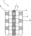
도 1 은, 실시형태에 관련된 꼰끈 형상 압전 소자의 구성예를 나타내는 모식도이다.
도 2 는, 도전층을 포함하는 실시형태에 관련된 꼰끈 형상 압전 소자의 구성예를 나타내는 모식도이다.
도 3 은, 실시형태 (양태 A) 에 관련된 꼰끈 형상 압전 소자와 금속제 단자의 접속예를 나타내는 모식도이다.
도 4 는, 도전층을 포함하는 실시형태 (양태 A) 에 관련된 꼰끈 형상 압전 소자와 금속제 단자의 접속예를 나타내는 모식도이다.
도 5 는, 실시형태 (양태 B 포크상) 에 관련된 꼰끈 형상 압전 소자와 금속제 단자의 접속예를 나타내는 모식도이다.
도 6 은, 실시형태 (양태 B 침상) 에 관련된 꼰끈 형상 압전 소자와 금속제 단자의 접속예를 나타내는 모식도이다.
도 7 은, 도전층을 포함하는 실시형태 (양태 B 포크상) 에 관련된 꼰끈 형상 압전 소자와 금속제 단자의 접속예를 나타내는 모식도이다.
도 8 은, 도전층을 포함하는 실시형태 (양태 B 침상) 에 관련된 꼰끈 형상 압전 소자와 금속제 단자의 접속예를 나타내는 모식도이다.
도 9 는, 실시형태에 관련된 포백 형상 압전 소자의 구성예를 나타내는 모식도이다.
도 10 은, 도전층을 포함하는 실시형태에 관련된 포백 형상 압전 소자의 구성예를 나타내는 모식도이다.
도 11 은, 실시형태에 관련된 압전 소자를 구비하는 디바이스를 나타내는 블록도이다.
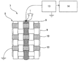
도 12 는, 실시형태에 관련된 포백 형상 압전 소자를 구비하는 디바이스의 구성예를 나타내는 모식도이다.
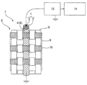
도 13 은, 실시형태에 관련된 포백 형상 압전 소자를 구비하는 디바이스의 구성예를 나타내는 모식도이다.
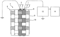
도 14 는, 실시형태에 관련된 포백 형상 압전 소자를 구비하는 디바이스의 다른 구성예를 나타내는 모식도이다.
도 15 는, 실시형태에 관련된 포백 형상 압전 소자를 구비하는 디바이스의 다른 구성예를 나타내는 모식도이다.1 is a schematic diagram showing a configuration example of a braided piezoelectric element according to an embodiment.
2 is a schematic diagram showing a configuration example of a braided piezoelectric element according to an embodiment including a conductive layer.
3 is a schematic diagram showing a connection example of a braided piezoelectric element and a metal terminal according to the embodiment (aspect A).
Fig. 4 is a schematic diagram showing a connection example of a braided piezoelectric element and a metallic terminal according to an embodiment (aspect A) including a conductive layer. Fig.
Fig. 5 is a schematic view showing an example of connection between a braided piezoelectric element and a metallic terminal relating to the embodiment (mode B fork). Fig.
Fig. 6 is a schematic diagram showing an example of connection between a braided piezoelectric element and a metallic terminal according to an embodiment (embodiment B needle bed). Fig.
7 is a schematic diagram showing an example of connection between a braided piezoelectric element and a metal terminal relating to an embodiment (a mode B fork) including a conductive layer.
8 is a schematic view showing an example of connection between a braided piezoelectric element and a metallic terminal relating to an embodiment including a conductive layer (Embodiment B needle).
Fig. 9 is a schematic diagram showing a configuration example of a fabric-like piezoelectric element according to the embodiment. Fig.
10 is a schematic view showing a configuration example of a fabric-like piezoelectric element according to an embodiment including a conductive layer.
11 is a block diagram showing a device including a piezoelectric element according to the embodiment.
Fig. 12 is a schematic diagram showing a configuration example of a device including a fabric-like piezoelectric element according to the embodiment. Fig.
Fig. 13 is a schematic diagram showing a configuration example of a device including a fabric-like piezoelectric element according to the embodiment. Fig.
Fig. 14 is a schematic diagram showing another configuration example of a device including a fabric-like piezoelectric element according to the embodiment. Fig.
15 is a schematic diagram showing another example of the configuration of a device including a fabric-like piezoelectric element according to the embodiment.
(꼰끈 형상 압전 소자) (Braided piezoelectric element)
도 1 은 실시형태에 관련된 꼰끈 형상 압전 소자의 구성예를 나타내는 모식도이다.1 is a schematic diagram showing a configuration example of a braided piezoelectric element according to an embodiment.
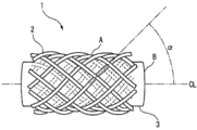
꼰끈 형상 압전 소자 (1) 는, 도전성 섬유 (B) 로 형성된 심부 (3) 와, 심부 (3) 를 피복하도록 꼰끈 형상의 압전성 섬유 (A) 로 형성된 초부 (2) 를 구비하고 있다. 압전성 섬유 (A) 는 주성분으로서 폴리락트산을 포함할 수 있다.The braided
도 2 는, 도전층을 포함하는 실시형태에 관련된 꼰끈 형상 압전 소자의 구성예를 나타내는 모식도이다.2 is a schematic diagram showing a configuration example of a braided piezoelectric element according to an embodiment including a conductive layer.
꼰끈 형상 압전 소자 (1) 는, 도전성 섬유 (B) 로 형성된 심부 (3) 와, 심부 (3) 를 피복하도록 꼰끈 형상의 압전성 섬유 (A) 로 형성된 초부 (2) 와, 초부 (2) 를 피복하는 도전층 (4) 을 구비하고 있다.The braided elastic
도전층 (4) 에 의한 초부 (2) 의 피복률은 25 % 이상이 바람직하다. 여기서 피복률이란, 도전층 (4) 을 초부 (2) 에 투영했을 때의 도전층 (4) 에 포함되는 도전성 영역의 면적과 초부 (2) 의 표면적의 비율이며, 그 값은 25 % 이상이 바람직하고, 50 % 이상이 보다 바람직하고, 75 % 이상인 것이 더욱 바람직하다. 도전층 (4) 의 피복률이 25 % 를 하회하면, 노이즈 신호의 억제 효과가 충분히 발휘되지 않는 경우가 있다. 도전성 영역이 도전층 (4) 의 표면에 노출되어 있지 않은 경우, 예를 들어 도전성 영역을 내포하는 섬유를 도전층 (4) 으로서 사용하여 초부 (2) 를 피복하고 있는 경우에는, 그 섬유의 초부 (2) 에 투영했을 때의 면적과 초부 (2) 의 표면적의 비율을 피복률로 할 수 있다.It is preferable that the covering ratio of the
도전성 영역이란, 도전층 (4) 에 포함되는 도전성을 담당하는 부분이며, 예를 들어, 도전층 (4) 을 도전성 섬유와 절연성 섬유로 구성한 경우의 도전성 섬유 부분을 가리킨다.The conductive region refers to a portion of the
꼰끈 형상 압전 소자 (1) 에서는, 적어도 1 개의 도전성 섬유 (B) 의 외주면을 다수의 압전성 섬유 (A) 가 치밀하게 둘러싸고 있다. 특정한 이론에 속박되는 것은 아니지만, 꼰끈 형상 압전 소자 (1) 에 변형이 발생하면, 다수의 압전성 섬유 (A) 각각에 변형에 의한 응력이 발생하고, 그에 따라 다수의 압전성 섬유 (A) 각각에 전기장이 발생하고 (압전 효과), 그 결과, 도전성 섬유 (B) 를 둘러싸는 다수의 압전성 섬유 (A) 의 전기장을 중첩한 전압 변화가 도전성 섬유 (B) 에 발생하는 것으로 추측된다. 즉 압전성 섬유 (A) 의 꼰끈 형상의 초부 (2) 를 사용하지 않는 경우와 비교하여 도전성 섬유 (B) 로부터의 전기 신호가 증대한다. 그에 따라, 꼰끈 형상 압전 소자 (1) 에서는, 비교적 작은 변형으로 발생하는 응력에 의해서도, 큰 전기 신호를 취출하는 것이 가능해진다. 또한, 도전성 섬유 (B) 는 복수 개여도 된다.In the braided
여기서, 압전성 섬유 (A) 는 주성분으로서 폴리락트산을 포함하는 것이 바람직하다. 「주성분으로서」 란, 압전성 섬유 (A) 의 성분 중 가장 많은 성분이 폴리락트산이라는 의미이다. 폴리락트산 중의 락트산 유닛은 90 몰% 이상인 것이 바람직하고, 95 몰% 이상인 것이 보다 바람직하고, 98 몰% 이상이 더욱 바람직하다.Here, the piezoelectric fiber (A) preferably contains polylactic acid as a main component. As the " main component ", it is meant that polylactic acid is the most component of the components of the piezoelectric fiber (A). The lactic acid unit in the polylactic acid is preferably 90 mol% or more, more preferably 95 mol% or more, and further preferably 98 mol% or more.
도전성 섬유 (B) 에 대한 압전성 섬유 (A) 의 휘감기 각도 (α) 는 15° 이상, 75° 이하인 것이 바람직하다. 즉, 도전성 섬유 (B) (심부 (3)) 의 중심축 (CL) 의 방향에 대하여, 압전성 섬유 (A) 의 휘감기 각도 (α) 는 15° 이상, 75° 이하인 것이 바람직하다. 단, 본 실시형태에서는, 도전성 섬유 (B) 의 중심축 (CL) 은, 압전성 섬유 (A) 의 꼰끈 (초부 (2)) 의 중심축 (이하, 「꼰끈축」 이라고도 한다.) 과 겹치기 때문에, 압전성 섬유 (A) 의 꼰끈축의 방향에 대하여, 압전성 섬유 (A) 의 휘감기 각도 (α) 는 15° 이상, 75° 이하인 것이 바람직하다고 할 수도 있다. 보다 큰 전기 신호를 취출하는 관점에서는, 각도 (α) 는 25° 이상, 65° 이하인 것이 보다 바람직하고, 35° 이상, 55° 이하인 것이 더욱 바람직하고, 40° 이상, 50° 이하인 것이 특히 바람직하다. 각도 (α) 가 이 각도 범위를 벗어나면, 압전성 섬유 (A) 에 발생하는 전계가 현저하게 저하되고, 그에 따라 도전성 섬유 (B) 로 얻어지는 전기 신호가 현저하게 저하되어 버리기 때문이다.It is preferable that the winding angle alpha of the piezoelectric fiber A with respect to the conductive fiber B is not less than 15 degrees and not more than 75 degrees. That is, the winding angle? Of the piezoelectric fiber A is preferably 15 ° or more and 75 ° or less with respect to the direction of the center axis CL of the conductive fiber B (the core portion 3). In the present embodiment, however, the center axis CL of the conductive fiber B overlaps with the center axis (hereinafter also referred to as " braid axis ") of the braid (the braid 2) of the piezoelectric fiber A , It may be said that the winding angle? Of the piezoelectric fiber (A) is preferably not less than 15 ° and not more than 75 ° with respect to the direction of the braid axis of the piezoelectric fiber (A). From the viewpoint of extracting a larger electric signal, the angle? Is more preferably 25 ° or more, more preferably 65 ° or less, still more preferably 35 ° or more, still more preferably 55 ° or less, particularly preferably 40 ° or more and 50 ° or less . If the angle? Is out of this range, the electric field generated in the piezoelectric fibers A is remarkably lowered, so that the electric signals obtained with the conductive fibers B are remarkably lowered.
또한, 상기 각도 (α) 에 대해서는, 초부 (2) 를 형성하는 압전성 섬유 (A) 의 주방향과 도전성 섬유 (B) 의 중심축 (CL) 이 이루는 각이라고도 말할 수 있으며, 압전성 섬유 (A) 의 일부가 느슨해져 있거나, 보풀이 일어 있어도 된다.The angle alpha is also referred to as the angle between the main direction of the piezoelectric fiber A forming the
여기서, 압전성 섬유 (A) 에 발생하는 전계가 현저하게 저하되는 이유는 이하와 같다. 압전성 섬유 (A) 는 폴리락트산을 주성분으로 하고, 압전성 섬유 (A) 의 섬유축의 방향으로 1 축 배향하고 있다. 여기서, 폴리락트산은, 그 배향 방향 (이 경우에는 압전성 섬유 (A) 의 섬유축의 방향) 에 대하여 전단 응력이 발생한 경우에 전계를 발생하지만, 그 배향 방향에 대하여 인장 응력이나 압축 응력이 발생한 경우에 전계를 그다지 발생하지 않는다. 따라서, 꼰끈축의 방향으로 평행하게 변형했을 때에 압전성 섬유 (A) 에 전단 응력이 발생하도록 하기 위해서는, 압전성 섬유 (A) (폴리락트산) 의 배향 방향이 꼰끈축에 대하여 소정의 각도 범위에 있는 것이 좋은 것으로 추측된다.Here, the reason why the electric field generated in the piezoelectric fiber (A) remarkably decreases is as follows. The piezoelectric fiber (A) has polylactic acid as a main component and is uniaxially oriented in the direction of the fiber axis of the piezoelectric fiber (A). Here, the polylactic acid generates an electric field when a shear stress occurs in the direction of its orientation (in this case, the direction of the fiber axis of the piezoelectric fiber (A)), but when tensile stress or compressive stress occurs in the direction of orientation The electric field is not generated very much. Therefore, in order to cause shear stress to be generated in the piezoelectric fiber (A) when it is deformed in parallel to the braid axis, it is preferable that the orientation direction of the piezoelectric fiber (A) (polylactic acid) is within a predetermined angular range with respect to the twisted string axis .
또한, 꼰끈 형상 압전 소자 (1) 에서는, 본 발명의 목적을 달성하는 한, 초부 (2) 에서는 압전성 섬유 (A) 이외의 다른 섬유와 조합하여 혼섬 등을 실시해도 되고, 심부 (3) 에서는 도전성 섬유 (B) 이외의 다른 섬유와 조합하여 혼섬 등을 실시해도 된다.In the braided
도전성 섬유 (B) 의 심부 (3) 와 꼰끈 형상의 압전성 섬유 (A) 의 초부 (2) 로 구성되는 꼰끈 형상 압전 소자, 또는 도전성 섬유 (B) 의 심부 (3) 와 꼰끈 형상의 압전성 섬유 (A) 의 초부 (2) 와, 초부 (2) 를 피복하는 도전층 (4) 으로 구성되는 꼰끈 형상 압전 소자의 길이는 특별히 한정은 없다. 예를 들어, 그 꼰끈 형상 압전 소자는 제조에 있어서 연속적으로 제조되고, 그 후에 필요한 길이로 절단하여 이용해도 된다. 꼰끈 형상 압전 소자의 길이는 1 ㎜ ∼ 10 m, 바람직하게는 5 ㎜ ∼ 2 m, 보다 바람직하게는 1 cm ∼ 1 m 이다. 길이가 지나치게 짧으면, 섬유 형상인 편리성이 상실되고, 또, 길이가 지나치게 길면, 도전성 섬유 (B) 의 저항값을 고려할 필요가 나올 것이다.Like piezoelectric element composed of the
이하, 각 구성에 대해 상세하게 설명한다.Hereinafter, each configuration will be described in detail.
(도전성 섬유) (Conductive fiber)
도전성 섬유 (B) 로는, 도전성을 나타내는 것이면 되고, 공지된 모든 것이 사용된다. 도전성 섬유 (B) 로는, 예를 들어, 금속 섬유, 도전성 고분자로 이루어지는 섬유, 탄소 섬유, 섬유상 혹은 입상 (粒狀) 의 도전성 필러를 분산시킨 고분자로 이루어지는 섬유, 혹은 섬유상물의 표면에 도전성을 갖는 층을 형성한 섬유를 들 수 있다. 섬유상물의 표면에 도전성을 갖는 층을 형성하는 방법으로는, 금속 코트, 도전성 고분자 코트, 도전성 섬유의 휘감기 등을 들 수 있다. 그 중에서도 금속 코트가 도전성, 내구성, 유연성 등의 관점에서 바람직하다. 금속을 코트하는 구체적인 방법으로는, 증착, 스퍼터, 전해 도금, 무전해 도금 등을 들 수 있지만, 생산성 등의 관점에서 도금이 바람직하다. 이와 같은 금속이 도금된 섬유는 금속 도금 섬유라고 할 수 있다.As the conductive fiber (B), any material that exhibits conductivity may be used, and all known materials are used. As the conductive fiber (B), for example, a metal fiber, a fiber composed of a conductive polymer, a carbon fiber, a fiber composed of a polymer in which a fibrous or granular conductive filler is dispersed, Are formed. Examples of the method for forming a layer having conductivity on the surface of the fibrous material include the winding of a metal coat, a conductive polymer coat, and a conductive fiber. Among them, a metal coat is preferable in view of conductivity, durability, flexibility and the like. As a specific method of coating the metal, vapor deposition, sputtering, electrolytic plating, electroless plating and the like can be mentioned, but plating is preferable from the viewpoint of productivity. Such a metal-plated fiber can be said to be a metal-plated fiber.
금속이 코트되는 베이스 섬유로서, 도전성의 유무에 상관없이 공지된 섬유를 사용할 수 있으며, 예를 들어, 폴리에스테르 섬유, 나일론 섬유, 아크릴 섬유, 폴리에틸렌 섬유, 폴리프로필렌 섬유, 염화비닐 섬유, 아라미드 섬유, 폴리술폰 섬유, 폴리에테르 섬유, 폴리우레탄 섬유 등의 합성 섬유 외에, 면, 마, 견 등의 천연 섬유, 아세테이트 등의 반합성 섬유, 레이온, 큐프라 등의 재생 섬유를 사용할 수 있다. 베이스 섬유는 이들에 한정되는 것이 아니라, 공지된 섬유를 임의로 사용할 수 있으며, 이들 섬유를 조합하여 사용해도 된다.As the base fiber on which the metal is coated, it is possible to use known fibers regardless of whether or not the fibers are conductive. For example, polyester fibers, nylon fibers, acrylic fibers, polyethylene fibers, polypropylene fibers, vinyl chloride fibers, aramid fibers, In addition to synthetic fibers such as polysulfone fibers, polyether fibers and polyurethane fibers, natural fibers such as cotton, hemp, and dog, semi-synthetic fibers such as acetate, and regenerated fibers such as rayon and cupra can be used. The base fibers are not limited to these, and known fibers may be arbitrarily used, and these fibers may be used in combination.
베이스 섬유에 코트되는 금속은 도전성을 나타내고, 본 발명의 효과를 발휘하는 한, 어느 것을 사용해도 된다. 예를 들어, 금, 은, 백금, 구리, 니켈, 주석, 아연, 팔라듐, 산화인듐주석, 황화구리 등, 및 이들의 혼합물이나 합금 등을 사용할 수 있다.The metal coated on the base fiber exhibits conductivity, and any of them may be used as long as the effect of the present invention is exerted. For example, gold, silver, platinum, copper, nickel, tin, zinc, palladium, indium tin oxide, copper sulfide, etc., and mixtures or alloys thereof may be used.
도전성 섬유 (B) 에 굴곡 내성이 있는 금속 코트한 유기 섬유를 사용하면, 도전성 섬유가 접히는 일이 매우 적고, 압전 소자를 사용한 센서로서의 내구성이나 안전성이 우수하다.The use of metal coated organic fibers having bending resistance in the conductive fibers (B) makes it very difficult to fold the conductive fibers and is excellent in durability and safety as sensors using piezoelectric elements.
도전성 섬유 (B) 는 필라멘트를 복수 개 묶은 멀티 필라멘트여도 되고, 또, 필라멘트 1 개로 이루어지는 모노 필라멘트여도 된다. 또 도전성 섬유 (B) 는, 1 개의 방적사여도 되고, 복수 개의 방적사를 묶은 실다발 형태 (연사 (撚絲) 를 포함한다) 로 해도 되고, 또한 필라멘트와 방적사를 조합한 장단 복합사로 해도 된다. 멀티 필라멘트 쪽이 전기 특성의 장척 (長尺) 안정성의 관점에서 바람직하다. 모노 필라멘트 또는 1 개의 방적사의 경우, 그 단사경 (單絲徑) 은 1 ㎛ ∼ 5000 ㎛ 이고, 바람직하게는 2 ㎛ ∼ 100 ㎛ 이다. 더욱 바람직하게는 3 ㎛ ∼ 50 ㎛ 이다. 멀티 필라멘트, 실다발 형태, 장단 복합사의 경우, 필라멘트 수 내지 실 수로는, 1 개 ∼ 100000 개가 바람직하고, 보다 바람직하게는 5 개 ∼ 500 개, 더욱 바람직하게는 10 개 ∼ 100 개이다. 단, 도전성 섬유 (B) 의 섬도·개수란, 꼰끈을 제조할 때에 사용하는 심부 (3) 의 섬도·개수이며, 복수 개의 단사 (모노 필라멘트) 로 형성되는 멀티 필라멘트도, 복수 개의 방적사를 묶은 실다발 형태 (연사를 포함한다) 도, 필라멘트와 방적사를 조합한 장단 복합사도, 모두 1 개의 도전성 섬유 (B) 로 세는 것으로 한다. 여기서 심부 (3) 란, 도전성 섬유 이외의 섬유를 사용한 경우이더라도, 그것을 포함한 전체의 양으로 한다.The conductive fiber (B) may be a multifilament in which a plurality of filaments are bundled, or may be a monofilament composed of one filament. The conductive fiber (B) may be a single yarn or may be a yarn bundle type (including twisted yarn) in which a plurality of yarns are bundled, or may be a long or short composite yarn in which filaments and yarns are combined. The multifilament is preferable from the viewpoint of long-term stability of electric characteristics. In the case of a monofilament or a single yarn, the single yarn diameter thereof is 1 mu m to 5,000 mu m, preferably 2 mu m to 100 mu m. And more preferably 3 mu m to 50 mu m. In the case of multifilament, yarn bundle type, and long multifilament yarn, the number of filaments to yarns is preferably 1 to 100,000, more preferably 5 to 500, and still more preferably 10 to 100. It should be noted that the fineness and the number of the conductive fibers (B) refer to the fineness and the number of the core portions (3) used for producing the braided cord, and the multifilament formed of a plurality of single filaments (monofilaments) The bundle type (including twisted yarn) is also counted as one conductive yarn (B), both long and short twisted yarns combined with filaments and yarns. Here, the
섬유의 직경이 작으면, 강도가 저하되어 핸들링이 곤란해지고, 또, 직경이 큰 경우에는 플렉시블성이 희생된다. 도전성 섬유 (B) 의 단면 형상으로는 원 또는 타원인 것이, 압전 소자의 설계 및 제조의 관점에서 바람직하지만, 이것에 한정되지 않는다.If the diameter of the fiber is small, the strength is lowered and the handling becomes difficult, and when the diameter is large, the flexibility is sacrificed. The cross-sectional shape of the conductive fiber (B) is preferably a circle or an ellipse in view of the design and production of the piezoelectric element, but is not limited thereto.
또, 압전성 고분자로부터의 전기 출력을 효율적으로 취출하기 위해서, 전기 저항은 낮은 것이 바람직하고, 체적 저항률로는 10-1 Ω·㎝ 이하인 것이 바람직하고, 보다 바람직하게는 10-2 Ω·㎝ 이하, 더욱 바람직하게는 10-3 Ω·㎝ 이하이다. 단, 전기 신호의 검출로 충분한 강도가 얻어지는 것이면 도전성 섬유 (B) 의 저항률은 이것에 한정되는 것은 아니다.In order to efficiently extract the electrical output from the piezoelectric polymer, the electrical resistance is preferably low, and the volume resistivity is preferably 10 -1 Ω · cm or less, more preferably 10 -2 Ω · cm or less, And more preferably 10 < -3 > OMEGA .cm or less. However, the resistivity of the conductive fiber (B) is not limited thereto as long as sufficient strength can be obtained by the detection of an electric signal.
도전성 섬유 (B) 는, 본 발명의 용도로부터, 반복된 구부림이나 비틀림과 같은 움직임에 대하여 내성이 없으면 안 된다. 그 지표로는, 결절 강도가, 보다 큰 것이 선호된다. 결절 강도는 JIS L1013:2010 8.6 의 방법으로 측정할 수 있다. 본 발명에 적당한 결절 강도의 정도로는, 0.5 cN/dtex 이상인 것이 바람직하고, 1.0 cN/dtex 이상인 것이 보다 바람직하고, 1.5 cN/dtex 이상인 것이 더욱 바람직하고, 2.0 cN/dtex 이상인 것이 가장 바람직하다. 또, 다른 지표로는, 굽힘 강성이, 보다 작은 것이 선호된다. 굽힘 강성은, 카토텍 (주) 제조 KES-FB2 순굽힘 시험기 등의 측정 장치로 측정되는 것이 일반적이다. 본 발명에 적당한 굽힘 강성의 정도로는, 토호 테낙스 (주) 제조의 탄소 섬유 “테낙스” (등록상표) HTS40-3K 보다 작은 편이 바람직하다. 구체적으로는, 도전성 섬유의 굽힘 강성이 0.05 × 10⁻⁴ N·㎡/m 이하인 것이 바람직하고, 0.02 × 10⁻⁴ N·㎡/m 이하인 것이 보다 바람직하고, 0.01 × 10⁻⁴ N·㎡/m 이하인 것이 더욱 바람직하다.From the use of the present invention, the conductive fibers (B) should be resistant to repeated bending and twisting movements. As an index thereof, it is preferable that the nodule strength is larger. The nodule strength can be measured by the method of JIS L1013: 2010 8.6. The degree of the nodule strength suitable for the present invention is preferably 0.5 cN / dtex or more, more preferably 1.0 cN / dtex or more, further preferably 1.5 cN / dtex or more, and most preferably 2.0 cN / dtex or more. As another index, it is preferable that the bending stiffness is smaller. The bending stiffness is generally measured by a measuring device such as a KES-FB2 net bending tester manufactured by KATO TEC CO., LTD. The degree of flexural rigidity suitable for the present invention is preferably smaller than that of carbon fiber " TEXACS " (registered trademark) HTS40-3K manufactured by Toho Tenax Co., Ltd. Specifically, the flexural rigidity of the conductive fiber 0.05 × 10 -4 N · ㎡ / m or less is preferable, and, 0.02 × 10 -4 N · ㎡ / m and more preferably less than or equal to, 0.01 × 10 -4 N · ㎡ / m or less.
(압전성 섬유) (Piezoelectric fiber)
압전성 섬유 (A) 의 재료인 압전성 고분자로는 폴리불화비닐리덴이나 폴리락트산과 같은 압전성을 나타내는 고분자를 이용할 수 있지만, 본 실시형태에서는 상기와 같이 압전성 섬유 (A) 는 주성분으로서 폴리락트산을 포함하는 것이 적합하다. 폴리락트산은, 예를 들어 용융 방사 후에 연신에 의해 용이하게 배향하여 압전성을 나타내고, 폴리불화비닐리덴 등으로 필요해지는 전계 배향 처리가 불필요한 점에서 생산성이 우수하다. 그러나 이것은, 본 발명을 실시할 때에 폴리불화비닐리덴 그 밖의 압전성 재료의 사용을 배제하는 것을 의도하는 것은 아니다.As the piezoelectric polymer as the material of the piezoelectric fiber (A), a polymer exhibiting piezoelectricity such as polyvinylidene fluoride or polylactic acid can be used. In the present embodiment, the piezoelectric fiber (A) contains polylactic acid as a main component Is suitable. Polylactic acid exhibits piezoelectricity by being easily oriented by stretching after melt-spinning, for example, and is excellent in productivity because no electric field alignment treatment required by polyvinylidene fluoride or the like is necessary. However, this is not intended to exclude the use of polyvinylidene fluoride or other piezoelectric material in the practice of the present invention.
폴리락트산으로는, 그 결정 구조에 의해, L-락트산, L-락티드를 중합하여 이루어지는 폴리-L-락트산, D-락트산, D-락티드를 중합하여 이루어지는 폴리-D-락트산, 또한, 그들의 하이브리드 구조로 이루어지는 스테레오 컴플렉스 폴리락트산 등이 있지만, 압전성을 나타내는 것이면 모두 이용할 수 있다. 압전율의 높이의 관점에서 바람직하게는, 폴리-L-락트산, 폴리-D-락트산이다. 폴리-L-락트산, 폴리-D-락트산은 각각, 동일한 응력에 대하여 분극이 반대가 되기 때문에, 목적에 따라 이들을 조합하여 사용하는 것도 가능하다.Examples of the polylactic acid include poly-L-lactic acid obtained by polymerizing L-lactic acid and L-lactide, poly-D-lactic acid obtained by polymerizing D-lactic acid and D-lactide, A stereo complex polylactic acid having a hybrid structure, and the like, but any material that exhibits piezoelectricity can be used. Poly-L-lactic acid and poly-D-lactic acid from the viewpoint of the height of the piezoelectric constant. Poly-L-lactic acid, and poly-D-lactic acid are opposite in polarization to each other under the same stress, they can be used in combination according to the purpose.
폴리락트산의 광학 순도는 99 % 이상인 것이 바람직하고, 99.3 % 이상인 것이 보다 바람직하고, 99.5 % 이상인 것이 더욱 바람직하다. 광학 순도가 99 % 미만이면, 현저하게 압전율이 저하되는 경우가 있고, 압전성 섬유 (A) 의 형상 변화에 의해 충분한 전기 신호를 얻는 것이 어려워지는 경우가 있다. 특히, 압전성 섬유 (A) 는, 주성분으로서 폴리-L-락트산 또는 폴리-D-락트산을 포함하고, 이들의 광학 순도가 99 % 이상인 것이 바람직하다.The optical purity of the polylactic acid is preferably 99% or more, more preferably 99.3% or more, still more preferably 99.5% or more. If the optical purity is less than 99%, the piezoelectric constant may decrease remarkably, and it may be difficult to obtain a sufficient electrical signal due to the shape change of the piezoelectric fiber (A). Particularly, the piezoelectric fiber (A) preferably contains poly-L-lactic acid or poly-D-lactic acid as a main component and has an optical purity of 99% or more.
폴리락트산을 주성분으로 하는 압전성 섬유 (A) 는, 제조시에 연신되어, 그 섬유축 방향으로 1 축 배향하고 있다. 또한, 압전성 섬유 (A) 는, 그 섬유축 방향으로 1 축 배향하고 있을 뿐만 아니라, 폴리락트산의 결정을 포함하는 것인 것이 바람직하고, 1 축 배향한 폴리락트산의 결정을 포함하는 것인 것이 보다 바람직하다. 왜냐하면, 폴리락트산은 그 결정성이 높음 및 1 축 배향하고 있음으로써 보다 큰 압전성을 나타내기 때문이다.The piezoelectric fiber (A) comprising polylactic acid as a main component is uniaxially oriented in its fiber axis direction after being stretched at the time of production. Further, it is preferable that the piezoelectric fiber (A) not only uniaxially orientate in the fiber axis direction but also include crystals of polylactic acid, and it is preferable that the piezoelectric fiber (A) includes crystals of polylactic acid uniaxially oriented desirable. This is because the polylactic acid exhibits higher piezoelectricity due to its high crystallinity and uniaxial orientation.
결정성 및 1 축 배향성은 호모 PLA 결정화도 Xhomo (%) 및 결정 배향도 Ao (%) 로 구해진다. 본 발명의 압전성 섬유 (A) 로는, 호모 PLA 결정화도 Xhomo (%) 및 결정 배향도 Ao (%) 가 하기 식 (1) 을 만족하는 것이 바람직하다.Crystallinity and uniaxial orientation are determined by homo PLA crystallinity X homo (%) and crystal orientation degree Ao (%). As the piezoelectric fiber (A) of the present invention, it is preferable that the homo PLA crystallinity X homo (%) and the crystal orientation degree Ao (%) satisfy the following formula (1).
Xhomo × Ao × Ao ÷ 106 ≥ 0.26 (1) X homo x Ao x Ao? 10 6 ? 0.26 (1)
상기 식 (1) 을 만족하지 않는 경우, 결정성 및/또는 1 축 배향성이 충분하지 않고, 동작에 대한 전기 신호의 출력값이 저하되거나, 특정 방향의 동작에 대한 신호의 감도가 저하되거나 할 우려가 있다. 상기 식 (1) 의 좌변의 값은, 0.28 이상이 보다 바람직하고, 0.3 이상이 더욱 바람직하다. 여기서, 각각의 값은 하기에 따라서 구한다.When the above formula (1) is not satisfied, there is a fear that the crystallinity and / or the uniaxial orientation are insufficient and the output value of the electric signal for the operation is lowered or the sensitivity of the signal to the operation in the specific direction is lowered have. The value of the left side of the formula (1) is more preferably 0.28 or more, and further preferably 0.3 or more. Here, the respective values are obtained as follows.
호모 폴리락트산 결정화도 Xhomo:Homopolylactic acid crystallinity X homo :
호모 폴리락트산 결정화도 Xhomo 에 대해서는, 광각 X 선 회절 분석 (WAXD) 에 의한 결정 구조 해석으로부터 구한다. 광각 X 선 회절 분석 (WAXD) 에서는, 리가쿠 제조 ultrax 18 형 X 선 회절 장치를 사용하여 투과법에 의해, 이하 조건으로 샘플의 X 선 회절 도형을 이미징 플레이트에 기록한다.The degree of homopolylactic acid crystallinity X homo is determined from crystal structure analysis by wide angle X-ray diffraction analysis (WAXD). In the wide-angle X-ray diffraction analysis (WAXD), an X-ray diffraction pattern of a sample was recorded on an imaging plate by a transmission method using an ultrax 18-type X-ray diffraction apparatus manufactured by Rigaku Corporation.
X 선원:Cu-Kα 선 (콘포컬 미러)X-ray source: Cu-K? Ray (confocal mirror)
출력:45 ㎸ × 60 ㎃ Output: 45 ㎸ × 60 ㎃
슬릿:1 st:1 ㎜Φ, 2 nd:0.8 ㎜ΦSlit: 1 st: 1 mmΦ, 2 nd: 0.8 mmΦ
카메라 길이:120 ㎜ Camera length: 120 mm
적산 시간:10 분 Accumulation time: 10 minutes
샘플:35 ㎎ 의 폴리락트산 섬유를 가지런히 모아 3 ㎝ 의 섬유 다발로 한다.Samples: 35 mg of polylactic acid fibers are bundled together into 3-cm bundles of fibers.
얻어지는 X 선 회절 도형에 있어서 방위각에 걸쳐서 전체 산란 강도 Itotal 을 구하고 여기서 2θ = 16.5°, 18.5°, 24.3° 부근에 나타나는 호모 폴리락트산 결정에서 유래하는 각 회절 피크의 적분 강도의 총합 ΣIHMi 를 구한다. 이들 값으로부터 하기 식 (2) 에 따라서, 호모 폴리락트산 결정화도 Xhomo 를 구한다.The total scattering intensity Itotal is obtained over the azimuth angle in the obtained X-ray diffraction pattern, and the total sum ΣIHMi of the integral intensities of the respective diffraction peaks derived from the homopolylactic acid crystals appearing in the vicinity of 2θ = 16.5 °, 18.5 ° and 24.3 ° is obtained. From these values, the degree of homopolylactic acid crystallization X homo is obtained according to the following formula (2).
호모 폴리락트산 결정화도 Xhomo (%) = ΣIHMi/Itotal × 100 (2) Homo polylactic acid crystallinity X homo (%) = ΣI HMi / I total × 100 (2)
또한, ΣIHMi 는, 전체 산란 강도에 있어서 백그라운드나 비정 (非晶) 에 의한 산만 산란을 공제함으로써 산출한다.Further, ΣI HMi is calculated by subtracting scattered scattering due to background or non-scattering in the whole scattering intensity.
(2) 결정 배향도 Ao:(2) Crystal orientation degree Ao:
결정 배향도 Ao 에 대해서는, 상기의 광각 X 선 회절 분석 (WAXD) 에 의해 얻어지는 X 선 회절 도형에 있어서, 동경 (動徑) 방향의 2θ = 16.5° 부근에 나타나는 호모 폴리락트산 결정에서 유래하는 회절 피크에 대해, 방위각 (°) 에 대한 강도 분포를 취하고, 얻어진 분포 프로파일의 반치폭의 총계 ΣWi (°) 로부터 다음 식 (3) 으로부터 산출한다.With regard to the crystal orientation degree Ao, the diffraction peak derived from the homopolylactic acid crystal appearing near the 2θ = 16.5 ° in the diameter direction in the X-ray diffraction pattern obtained by the above wide angle X-ray diffraction analysis (WAXD) , An intensity distribution with respect to the azimuth angle (deg.) Is taken, and is calculated from the following formula (3) from the sum of the half widths of the obtained distribution profiles [Sigma Wi (°)].
결정 배향도 Ao (%) = (360 ― ΣWi) ÷ 360 × 100 (3)Crystal orientation Ao (%) = (360 - ΣW i) ÷ 360 × 100 (3)
또한, 폴리락트산은 가수 분해가 비교적 빠른 폴리에스테르이기 때문에, 내습열성이 문제가 되는 경우에 있어서는, 공지된, 이소시아네이트 화합물, 옥사졸린 화합물, 에폭시 화합물, 카르보디이미드 화합물 등의 가수 분해 방지제를 첨가해도 된다. 또, 필요에 따라 인산계 화합물 등의 산화 방지제, 가소제, 광 열화 방지제 등을 첨가하여 물성 개량해도 된다.In addition, when polylactic acid is a polyester having a relatively high hydrolysis, it is preferable to add a known hydrolysis inhibitor such as an isocyanate compound, an oxazoline compound, an epoxy compound or a carbodiimide compound do. If necessary, an antioxidant such as a phosphate compound, a plasticizer, a photo-deterioration inhibitor or the like may be added to improve the physical properties.
또, 폴리락트산은 다른 폴리머와의 앨로이로서 사용해도 되지만, 폴리락트산을 주된 압전성 고분자로서 사용한다면, 앨로이의 전체 질량을 기준으로 하여 적어도 50 질량% 이상으로 폴리락트산을 함유하고 있는 것이 바람직하고, 더욱 바람직하게는 70 질량% 이상, 가장 바람직하게는 90 질량% 이상이다.The polylactic acid may be used as an ally with another polymer. If polylactic acid is used as the main piezoelectric polymer, it is preferable that the polylactic acid contains at least 50 mass% or more based on the total mass of the ally. More preferably not less than 70% by mass, and most preferably not less than 90% by mass.
앨로이로 하는 경우의 폴리락트산 이외의 폴리머로는, 폴리부틸렌테레프탈레이트, 폴리에틸렌테레프탈레이트, 폴리에틸렌나프탈레이트 공중합체, 폴리메타크릴레이트 등을 적합한 예로서 들 수 있지만, 이들에 한정되는 것이 아니라, 본 발명에서 목적으로 하는 압전성을 나타내는 한, 어떠한 폴리머를 사용해도 된다.Examples of the polymer other than polylactic acid in the case of aloe include polybutylene terephthalate, polyethylene terephthalate, polyethylene naphthalate copolymer, polymethacrylate and the like, but the present invention is not limited thereto. Any polymer may be used as long as it exhibits the piezoelectric property intended by the invention.
압전성 섬유 (A) 는 필라멘트를 복수 개 묶은 멀티 필라멘트여도 되고, 또, 필라멘트 1 개로 이루어지는 모노 필라멘트여도 되고, 1 개의 방적사여도 되고, 복수 개의 방적사를 묶은 실다발 형태 (연사를 포함한다) 로 해도 되며, 또한, 필라멘트와 방적사를 조합한 장단 복합사로 해도 된다. 모노 필라멘트 또는 1 개의 방적사의 경우, 그 단사경은 1 ㎛ ∼ 5 ㎜ 이고, 바람직하게는 5 ㎛ ∼ 2 ㎜, 더욱 바람직하게는 10 ㎛ ∼ 1 ㎜ 이다. 멀티 필라멘트의 경우, 그 단사경은 0.1 ㎛ ∼ 5 ㎜ 이고, 바람직하게는 2 ㎛ ∼ 100 ㎛, 더욱 바람직하게는 3 ㎛ ∼ 50 ㎛ 이다. 멀티 필라멘트, 실다발 형태, 장단 복합사의 필라멘트 수 내지 실 수로는, 1 개 ∼ 100000 개가 바람직하고, 보다 바람직하게는 50 개 ∼ 50000 개, 더욱 바람직하게는 100 개 ∼ 20000 개이다. 단, 압전성 섬유 (A) 의 섬도나 개수에 대해서는, 꼰끈을 제조할 때의 캐리어 1 개당의 섬도, 개수이며, 복수 개의 단사 (모노 필라멘트) 로 형성되는 멀티 필라멘트도 1 개의 압전성 섬유 (A) 로 세는 것으로 한다. 여기서, 캐리어 1 개 중에, 압전성 섬유 이외의 섬유를 사용한 경우이더라도, 그것을 포함한 전체의 양으로 한다.The piezoelectric fiber A may be a multifilament in which a plurality of filaments are bundled, a monofilament composed of one filament, a single yarn, or a yarn bundle (including twist yarn) in which a plurality of yarns are bundled , Or a long or short composite yarn in which filaments and yarns are combined. In the case of a monofilament or a single yarn, the single-filament has a diameter of 1 to 5 mm, preferably 5 to 2 mm, more preferably 10 to 1 mm. In the case of multifilaments, the short diameter is 0.1 to 5 mm, preferably 2 to 100 m, and more preferably 3 to 50 m. The number of filaments to yarns of the multifilament, the yarn bundle form, and the long and short composite yarn is preferably 1 to 100,000, more preferably 50 to 50,000, and still more preferably 100 to 20,000. However, the number and the number of the piezoelectric fibers (A) are fineness and the number per one carrier when the braided cord is produced, and the multifilament formed of a plurality of single filaments (monofilament) I will count. Here, even if fibers other than the piezoelectric fibers are used in one carrier, the total amount including the fibers is used.
이와 같은 압전성 고분자를 압전성 섬유 (A) 로 하기 위해서는, 고분자로부터 섬유화하기 위한 공지된 수법을, 본 발명의 효과를 발휘하는 한 모두 채용할 수 있다. 예를 들어, 압전성 고분자를 압출 성형하여 섬유화하는 수법, 압전성 고분자를 용융 방사하여 섬유화하는 수법, 압전성 고분자를 건식 혹은 습식 방사에 의해 섬유화하는 수법, 압전성 고분자를 정전 방사에 의해 섬유화하는 수법, 필름을 형성한 후에 가늘게 컷하는 수법 등을 채용할 수 있다. 이들 방사 조건은, 채용하는 압전성 고분자에 따라 공지된 수법을 적용하면 되고, 통상적으로는 공업적으로 생산이 용이한 용융 방사법을 채용하면 된다. 또한, 섬유를 형성 후에는 형성된 섬유를 연신한다. 그에 따라 1 축 연신 배향하고 또한 결정을 포함하는 큰 압전성을 나타내는 압전성 섬유 (A) 가 형성된다.In order to convert such a piezoelectric polymer into a piezoelectric fiber (A), any known method for converting a polymer into a fiber can be employed as long as it exerts the effects of the present invention. For example, a method of extruding a piezoelectric polymer to form a fiber, a method of fiberizing a piezoelectric polymer by melt spinning, a method of forming a piezoelectric polymer by dry or wet spinning, a method of forming a piezoelectric polymer by electrospinning, And a method of finely cutting after forming can be adopted. These spinning conditions may be applied by a known method depending on the piezoelectric polymer to be employed, and usually melt spinning which is industrially easy to produce may be employed. After forming the fibers, the formed fibers are stretched. Thereby, the piezoelectric fiber (A) having a monoaxially stretched orientation and exhibiting a large piezoelectric property including crystals is formed.
또, 압전성 섬유 (A) 는, 상기와 같이 제조된 것을 꼰끈으로 하기 전에, 염색, 연사, 합사, 열 처리 등의 처리를 할 수 있다.The piezoelectric fiber (A) can be subjected to treatments such as dyeing, twisting, padding, heat treatment and the like before the braided cord is produced as described above.
또한, 압전성 섬유 (A) 는, 꼰끈을 형성할 때에 섬유끼리가 스쳐 단사되거나, 보풀이 일거나 하는 경우가 있기 때문에, 그 강도와 내마모성은 높은 편이 바람직하며, 강도는 1.5 cN/dtex 이상인 것이 바람직하고, 2.0 cN/dtex 이상인 것이 보다 바람직하고, 2.5 cN/dtex 이상인 것이 더욱 바람직하고, 3.0 cN/dtex 이상인 것이 가장 바람직하다. 내마모성은, JIS L1095 9.10.2 B 법 등으로 평가할 수 있고, 마찰 횟수는 100 회 이상이 바람직하고, 1000 회 이상인 것이 보다 바람직하고, 5000 회 이상인 것이 더욱 바람직하고, 10000 회 이상인 것이 가장 바람직하다. 내마모성을 향상시키기 위한 방법은 특별히 한정되는 것이 아니라, 공지된 모든 방법을 이용할 수 있으며, 예를 들어, 결정화도를 향상시키거나, 미립자를 첨가하거나, 표면 가공하거나 할 수 있다. 또, 꼰끈으로 가공할 때에, 섬유에 윤활제를 도포하여 마찰을 저감시킬 수도 있다.The piezoelectric fiber (A) is preferably one having high strength and abrasion resistance, and has a strength of not less than 1.5 cN / dtex because the fibers may be cross-wound or fluffy when the twine is formed More preferably 2.0 cN / dtex or more, further preferably 2.5 cN / dtex or more, and most preferably 3.0 cN / dtex or more. The abrasion resistance can be evaluated by the JIS L1095 9.10.2 B method, and the number of friction is preferably 100 times or more, more preferably 1,000 times or more, more preferably 5,000 times or more, and most preferably 10,000 times or more. The method for improving the abrasion resistance is not particularly limited, and any known method can be used. For example, the degree of crystallization can be improved, the fine particles can be added, or the surface can be processed. In addition, when machining with a braided cord, friction can be reduced by applying a lubricant to the fibers.
또, 압전성 섬유의 수축률은, 전술한 도전성 섬유의 수축률과의 차가 작은 것이 바람직하다. 수축률차가 크면, 꼰끈 제조 후나 포백 제조 후의 후처리 공정이나 실 사용시에 열이 가해졌을 때나 시간 경과적 변화에 의해 꼰끈이 구부러지거나, 포백의 평탄성이 나빠지거나, 압전 신호가 약해져 버리는 경우가 있다. 수축률을 후술하는 비수 (沸水) 수축률로 정량화한 경우, 압전성 섬유의 비수 수축률 S(p) 및 도전성 섬유의 비수 수축률 S(c) 가 하기 식 (4) 를 만족하는 것이 적합하다. It is preferable that the shrinkage percentage of the piezoelectric fiber is smaller than the shrinkage percentage of the above-described conductive fiber. If the difference in the shrinkage percentage is large, the braided cord may be bent, the flatness of the warp, or the piezoelectric signal may be weakened due to the heat treatment or the time-dependent change in the post-treatment process after the manufacture of the braid or after the production thereof. It is preferable that the non-water shrinkage ratio S (p) of the piezoelectric fiber and the non-water shrinkage ratio S (c) of the conductive fiber satisfy the following formula (4) when the shrinkage percentage is quantified as a boiling water shrinkage rate described later.
|S(p) ― S(c)| ≤ 10 (4) | S (p) - S (c) | 10 (4)
상기 식 (4) 의 좌변은 5 이하인 것이 보다 바람직하고, 3 이하이면 더욱 바람직하다.The left side of the formula (4) is more preferably 5 or less, and more preferably 3 or less.
또, 압전성 섬유의 수축률은, 도전성 섬유 이외의 섬유, 예를 들어 절연성 섬유의 수축률과의 차도 작은 것이 바람직하다. 수축률차가 크면, 꼰끈 제조 후나 포백 제조 후의 후처리 공정이나 실 사용시에 열이 가해졌을 때나 시간 경과적 변화에 의해 꼰끈이 구부러지거나, 포백의 평탄성이 나빠지거나, 압전 신호가 약해져 버리는 경우가 있다. 수축률을 비수 수축률로 정량화한 경우, 압전성 섬유의 비수 수축률 S(p) 및 절연성 섬유의 비수 수축률 S(i) 가 하기 식 (5) 를 만족하는 것이 바람직하다.It is also preferable that the shrinkage ratio of the piezoelectric fiber is smaller than the shrinkage ratio of the fibers other than the conductive fibers, for example, the insulating fiber. If the difference in the shrinkage percentage is large, the braided cord may be bent, the flatness of the warp, or the piezoelectric signal may be weakened due to the heat treatment or the time-dependent change in the post-treatment process after the manufacture of the braid or after the production thereof. When the shrinkage ratio is quantified as the non-water shrinkage ratio, it is preferable that the non-water shrinkage ratio S (p) of the piezoelectric fiber and the non-water shrinkage ratio S (i) of the insulating fiber satisfy the following formula (5).
|S(p) ― S(i) | ≤ 10 (5) | S (p) - S (i) | ≤ 10 (5)
상기 식 (5) 의 좌변은 5 이하인 것이 보다 바람직하고, 3 이하이면 더욱 바람직하다.The left side of the formula (5) is more preferably 5 or less, and more preferably 3 or less.
또, 압전성 섬유의 수축률은 작은 편이 바람직하다. 예를 들어 수축률을 비수 수축률로 정량화한 경우, 압전성 섬유의 수축률은 15 % 이하인 것이 바람직하고, 보다 바람직하게는 10 % 이하, 더욱 바람직하게는 5 % 이하, 가장 바람직하게는 3 % 이하이다. 수축률을 낮추는 수단으로는, 공지된 모든 방법을 적용할 수 있으며, 예를 들어, 열 처리에 의해 비정부의 배향 완화나 결정화도를 올림으로써 수축률을 저감할 수 있고, 열 처리를 실시하는 타이밍은 특별히 한정되지 않고, 연신 후, 연사 후, 꼰끈화 후, 포백화 후 등을 들 수 있다. 또한, 상기 서술한 비수 수축률은 이하의 방법으로 측정하는 것으로 한다. 프레임 둘레 1.125 m 의 검척기로 감김 수 20 회의 실패를 만들고, 0.022 cN/dtex 의 하중을 걸어, 스케일판에 매달아 초기의 실패 길이 L0 를 측정하였다. 그 후, 이 실패를 100 ℃ 의 비등수 욕 중에서 30 분간 처리 후, 방랭하고 다시 상기 하중을 걸어 스케일판에 매달고 수축 후의 실패 길이 L 을 측정하였다. 측정된 L0 및 L 을 이용하여 하기 식 (6) 에 의해 비수 수축률을 계산한다.The shrinkage ratio of the piezoelectric fiber is preferably small. For example, when the shrinkage percentage is quantified as the non-water shrinkage percentage, the shrinkage percentage of the piezoelectric fiber is preferably 15% or less, more preferably 10% or less, further preferably 5% or less, and most preferably 3% or less. As the means for lowering the shrinkage percentage, any known method can be applied. For example, the shrinkage ratio can be reduced by increasing the orientation relaxation and crystallinity of the non-crystalline portion by heat treatment, and the timing of heat treatment is particularly limited After stretching, after twisting, after braiding, after baking, and the like. In addition, the above-mentioned non-water shrinkage percentage is measured by the following method. The initial failure length L0 was measured by hanging on a scale plate by applying a load of 0.022 cN / dtex, making a failure of 20 turns with a caliper of 1.125 m around the frame. Thereafter, this failure was treated in a boiling water bath of 100 캜 for 30 minutes, then allowed to cool, and then the load was applied to the scale plate to measure the failure length L after shrinkage. Using the measured L0 and L, the non-water shrinkage ratio is calculated by the following equation (6).
비수 수축률 = (L0 ― L) /L0 × 100 (%) (6) Water Shrinkage Ratio = (L0 - L) / L0 100 (%) (6)
(피복) (covering)
도전성 섬유 (B), 즉 심부 (3) 는, 압전성 섬유 (A), 즉 꼰끈 형상의 초부 (2) 로 표면이 피복되어 있다. 도전성 섬유 (B) 를 피복하는 초부 (2) 의 두께는 1 ㎛ ∼ 10 ㎜ 인 것이 바람직하고, 5 ㎛ ∼ 5 ㎜ 인 것이 보다 바람직하고, 10 ㎛ ∼ 3 ㎜ 인 것이 더욱 바람직하다, 20 ㎛ ∼ 1 ㎜ 인 것이 가장 바람직하다. 지나치게 얇으면, 강도의 점에서 문제가 되는 경우가 있고, 또, 지나치게 두꺼우면, 꼰끈 형상 압전 소자 (1) 가 단단해져 변형하기 어려워지는 경우가 있다. 또한, 여기서 말하는 초부 (2) 란, 심부 (3) 에 인접하는 층을 가리킨다.The conductive fiber B, that is, the
꼰끈 형상 압전 소자 (1) 에 있어서, 초부 (2) 의 압전성 섬유 (A) 의 총 섬도는, 심부 (3) 의 도전성 섬유 (B) 의 총 섬도의 1/2 배 이상, 20 배 이하인 것이 바람직하고, 1 배 이상, 15 배 이하인 것이 보다 바람직하고, 2 배 이상, 10 배 이하인 것이 더욱 바람직하다. 압전성 섬유 (A) 의 총 섬도가 도전성 섬유 (B) 의 총 섬도에 대하여 지나치게 작으면, 도전성 섬유 (B) 를 둘러싸는 압전성 섬유 (A) 가 지나치게 적어 도전성 섬유 (B) 가 충분한 전기 신호를 출력할 수 없고, 또한 도전성 섬유 (B) 가 근접하는 다른 도전성 섬유에 접촉할 우려가 있다. 압전성 섬유 (A) 의 총 섬도가 도전성 섬유 (B) 의 총 섬도에 대하여 지나치게 크면, 도전성 섬유 (B) 를 둘러싸는 압전성 섬유 (A) 가 지나치게 많아 꼰끈 형상 압전 소자 (1) 가 단단해져 변형하기 어려워진다. 즉, 어느 경우에도 꼰끈 형상 압전 소자 (1) 가 센서로서 충분히 기능하지 않게 된다.It is preferable that the total fineness of the piezoelectric fiber (A) in the sheath type piezoelectric element (1) is not less than 1/2 and not more than 20 times the total fineness of the conductive fibers (B) More preferably not less than 1 times and not more than 15 times, more preferably not less than 2 times and not more than 10 times. If the total fineness of the piezoelectric fibers A is excessively small relative to the total fineness of the conductive fibers B, the amount of the piezoelectric fibers A surrounding the conductive fibers B is too small, There is a possibility that the conductive fibers (B) are in contact with other adjacent conductive fibers. If the total fineness of the piezoelectric fibers A is excessively large relative to the total fineness of the conductive fibers B, the number of the piezoelectric fibers A surrounding the conductive fibers B is excessively large, Loses. That is, in any case, the braided
여기서 말하는 총 섬도란, 초부 (2) 를 구성하는 압전성 섬유 (A) 모든 섬도의 합이며, 예를 들어, 일반적인 8 타 꼰끈의 경우에는, 8 개 섬유의 섬도의 총합이 된다.Here, the total sum of the finenesses refers to the sum of all the finenesses of the piezoelectric fibers (A) constituting the
또, 꼰끈 형상 압전 소자 (1) 에 있어서, 초부 (2) 의 압전성 섬유 (A) 의 1 개당 섬도는, 도전성 섬유 (B) 의 총 섬도의 1/20 배 이상, 2 배 이하인 것이 바람직하고, 1/15 배 이상, 1.5 배 이하인 것이 보다 바람직하고, 1/10 배 이상, 1 배 이하인 것이 더욱 바람직하다. 압전성 섬유 (A) 1 개당 섬도가 도전성 섬유 (B) 의 총 섬도에 대하여 지나치게 작으면, 압전성 섬유 (A) 가 지나치게 적어 도전성 섬유 (B) 가 충분한 전기 신호를 출력할 수 없고, 또한 압전성 섬유 (A) 가 절단될 우려가 있다. 압전성 섬유 (A) 1 개당 섬도가 도전성 섬유 (B) 의 총 섬도에 대하여 지나치게 크면, 압전성 섬유 (A) 가 지나치게 굵어 꼰끈 형상 압전 소자 (1) 가 단단해져 변형하기 어려워진다. 즉, 어느 경우에도 꼰끈 형상 압전 소자 (1) 가 센서로서 충분히 기능하지 않게 된다. In the braided
또한, 도전성 섬유 (B) 에 금속 섬유를 사용한 경우나, 금속 섬유를 도전성 섬유 (A) 혹은 압전성 섬유 (B) 에 혼섬한 경우에는, 섬도의 비율은 상기에 한정되는 것은 아니다. 본 발명에 있어서, 상기 비율은, 접촉 면적이나 피복률, 즉, 면적 및 체적의 관점에서 중요하기 때문이다. 예를 들어, 각각의 섬유의 비중이 2 를 초과하는 경우에는, 섬유의 평균 단면적의 비율이 상기 섬도의 비율인 것이 바람직하다.When the metal fibers are used for the conductive fibers (B), or when the metal fibers are mixed with the conductive fibers (A) or the piezoelectric fibers (B), the ratio of the fineness is not limited to the above. In the present invention, the ratio is important from the viewpoint of the contact area and coverage rate, that is, the area and the volume. For example, when the specific gravity of each fiber exceeds 2, the ratio of the average cross-sectional area of the fibers is preferably the ratio of the fineness.
압전성 섬유 (A) 와 도전성 섬유 (B) 는 가능한 한 밀착되어 있는 것이 바람직하지만, 밀착성을 개량하기 위해서, 도전성 섬유 (B) 와 압전성 섬유 (A) 사이에 앵커층이나 접착층 등을 형성해도 된다.It is preferable that the piezoelectric fibers A and the conductive fibers B are in close contact with each other as much as possible. However, in order to improve the adhesion, an anchor layer, an adhesive layer, or the like may be formed between the conductive fibers B and the piezoelectric fibers A.
피복의 방법은 도전성 섬유 (B) 를 심사 (芯絲) 로 하여, 그 둘레에 압전성 섬유 (A) 를 꼰끈 형상으로 휘감는 방법이 취해진다. 한편, 압전성 섬유 (A) 의 꼰끈의 형상은, 인가된 하중으로 발생하는 응력에 대하여 전기 신호를 출력할 수 있으면 특별히 한정되는 것은 아니지만, 심부 (3) 를 갖는 8 타 꼰끈이나 16 타 꼰끈이 바람직하다.The covering method is a method in which the conductive fiber (B) is used as a core yarn and the piezoelectric fiber (A) is wound around the conductive fiber (B) in the form of a braided cord. On the other hand, the shape of the braided band of the piezoelectric fiber (A) is not particularly limited as long as it can output an electric signal with respect to the stress generated by the applied load, but it is preferable to use 8 braided cord or 16 braided cord having the core portion Do.
도전성 섬유 (B) 와 압전성 섬유 (A) 의 형상으로는 특별히 한정되는 것은 아니지만, 가능한 한 동심원상에 가까운 것이 바람직하다. 또한, 도전성 섬유 (B) 로서 멀티 필라멘트를 사용하는 경우, 압전성 섬유 (A) 는, 도전성 섬유 (B) 의 멀티 필라멘트의 표면 (섬유 둘레면) 의 적어도 일부가 접촉하고 있도록 피복하고 있으면 되고, 멀티 필라멘트를 구성하는 모든 필라멘트 표면 (섬유 둘레면) 에 압전성 섬유 (A) 가 피복하고 있어도 되고, 피복하고 있지 않아도 된다. 도전성 섬유 (B) 의 멀티 필라멘트를 구성하는 내부의 각 필라멘트에 대한 압전성 섬유 (A) 의 피복 상태는, 압전성 소자로서의 성능, 취급성 등을 고려하여, 적절히 설정하면 된다.The shape of the conductive fibers (B) and the piezoelectric fibers (A) is not particularly limited, but is preferably as close to a concentric circle as possible. When the multifilament is used as the conductive fiber (B), the piezoelectric fiber (A) may be coated so that at least part of the surface of the multifilament of the conductive fiber (B) All the filament surfaces (fiber circumferential surfaces) constituting the filaments may or may not be covered with the piezoelectric fiber (A). The covering state of the piezoelectric fibers A with respect to the respective internal filaments constituting the multifilament of the conductive fibers (B) may be suitably set in consideration of the performance as a piezoelectric element, handling property, and the like.
본 발명의 꼰끈 형상 압전 소자 (1) 는, 그 표면에 전극을 존재시킬 필요가 없기 때문에, 꼰끈 형상 압전 소자 (1) 자체를 또한 피복할 필요가 없고, 또, 오동작하기 어렵다는 이점이 있다.Since the braided
(도전층) (Conductive layer)
도전층 (4) 의 양태로는, 코팅 외에, 필름, 포백, 섬유 휘감기가 생각되며, 또 그것들을 조합해도 된다.As for the mode of the
도전층 (4) 을 형성하는 코팅에는 도전성을 나타내는 물질을 포함하는 것이 사용되고 있으면 되고, 공지된 모든 것이 사용된다. 예를 들어, 금속, 도전성 고분자, 도전성 필러를 분산시킨 고분자를 들 수 있다.The coating for forming the
도전층 (4) 을 필름의 휘감기에 의해 형성하는 경우에는, 도전성 고분자, 도전성 필러를 분산시킨 고분자를 제막 (製膜) 하여 얻어지는 필름이 사용되며, 또 표면에 도전성을 갖는 층을 형성한 필름이 사용되어도 된다.When the
도전층 (4) 을 포백의 휘감기에 의해 형성하는 경우에는, 후술하는 도전성 섬유 (6) 를 구성 성분으로 하는 포백이 사용된다.In the case where the
도전층 (4) 을 섬유 휘감기에 의해 형성하는 경우, 그 수법으로는, 커버 링, 편물, 조물 (組物) 이 생각된다. 또, 사용하는 섬유는, 도전성 섬유 (6) 이며, 도전성 섬유 (6) 는, 상기 도전성 섬유 (B) 와 동일 종이어도 되고 이종의 도전성 섬유여도 된다. 도전성 섬유 (6) 로는, 예를 들어, 금속 섬유, 도전성 고분자로 이루어지는 섬유, 탄소 섬유, 섬유상 혹은 입상의 도전성 필러를 분산시킨 고분자로 이루어지는 섬유, 혹은 섬유상물의 표면에 도전성을 갖는 층을 형성한 섬유를 들 수 있다. 섬유상물의 표면에 도전성을 갖는 층을 형성하는 방법으로는, 금속 코트, 도전성 고분자 코트, 도전성 섬유의 휘감기 등을 들 수 있다. 그 중에서도 금속 코트가 도전성, 내구성, 유연성 등의 관점에서 바람직하다. 금속을 코트하는 구체적인 방법으로는, 증착, 스퍼터, 전해 도금, 무전해 도금 등을 들 수 있지만, 생산성 등의 관점에서 도금이 바람직하다. 이와 같은 금속이 도금된 섬유는 금속 도금 섬유라고 할 수 있다.When the
금속이 코트되는 베이스 섬유로서, 도전성의 유무에 상관없이 공지된 섬유를 사용할 수 있으며, 예를 들어, 폴리에스테르 섬유, 나일론 섬유, 아크릴 섬유, 폴리에틸렌 섬유, 폴리프로필렌 섬유, 염화비닐 섬유, 아라미드 섬유, 폴리술폰 섬유, 폴리에테르 섬유, 폴리우레탄 섬유 등의 합성 섬유 외에, 면, 마, 견 등의 천연 섬유, 아세테이트 등의 반합성 섬유, 레이온, 큐프라 등의 재생 섬유를 사용할 수 있다. 베이스 섬유는 이들에 한정되는 것이 아니라, 공지된 섬유를 임의로 사용할 수 있으며, 이들 섬유를 조합하여 사용해도 된다.As the base fiber on which the metal is coated, it is possible to use known fibers regardless of whether or not the fibers are conductive. For example, polyester fibers, nylon fibers, acrylic fibers, polyethylene fibers, polypropylene fibers, vinyl chloride fibers, aramid fibers, In addition to synthetic fibers such as polysulfone fibers, polyether fibers and polyurethane fibers, natural fibers such as cotton, hemp, and dog, semi-synthetic fibers such as acetate, and regenerated fibers such as rayon and cupra can be used. The base fibers are not limited to these, and known fibers may be arbitrarily used, and these fibers may be used in combination.
베이스 섬유에 코트되는 금속은 도전성을 나타내고, 본 발명의 효과를 발휘하는 한, 어느 것을 사용해도 된다. 예를 들어, 금, 은, 백금, 구리, 니켈, 주석, 아연, 팔라듐, 산화인듐주석, 황화구리 등, 및 이들의 혼합물이나 합금 등을 사용할 수 있다.The metal coated on the base fiber exhibits conductivity, and any of them may be used as long as the effect of the present invention is exerted. For example, gold, silver, platinum, copper, nickel, tin, zinc, palladium, indium tin oxide, copper sulfide, etc., and mixtures or alloys thereof may be used.
도전성 섬유 (6) 에 굴곡 내성이 있는 금속 코트한 유기 섬유를 사용하면, 도전성 섬유가 접히는 일이 매우 적고, 압전 소자를 사용한 센서로서의 내구성이나 안전성이 우수하다.When the
도전성 섬유 (6) 는 필라멘트를 복수 개 묶은 멀티 필라멘트여도 되고, 또, 필라멘트 1 개로 이루어지는 모노 필라멘트여도 되고, 1 개의 방적사여도 되고, 복수 개의 방적사를 묶은 실다발 형태 (연사를 포함한다) 로 해도 되며, 또한, 필라멘트와 방적사를 조합한 장단 복합사로 해도 된다. 멀티 필라멘트 쪽이 전기 특성의 장척 안정성의 관점에서 바람직하다. 모노 필라멘트 또는 1 개의 방적사의 경우, 그 단사경은 1 ㎛ ∼ 5000 ㎛ 이고, 바람직하게는 2 ㎛ ∼ 100 ㎛ 이다. 더욱 바람직하게는 3 ㎛ ∼ 50 ㎛ 이다. 멀티 필라멘트, 실다발 형태, 장단 복합사의 경우, 필라멘트 내지 실 수로는, 1 개 ∼ 100000 개가 바람직하고, 보다 바람직하게는 5 개 ∼ 500 개, 더욱 바람직하게는 10 개 ∼ 100 개이다.The
섬유의 직경이 작으면, 강도가 저하되고 핸들링이 곤란해지고, 또, 직경이 큰 경우에는 플렉시블성이 희생된다. 도전성 섬유 (6) 의 단면 형상으로는 원 또는 타원인 것이, 압전 소자의 설계 및 제조의 관점에서 바람직하지만, 이것에 한정되지 않는다.If the diameter of the fiber is small, the strength is lowered and handling becomes difficult, and when the diameter is large, the flexibility is sacrificed. The cross-sectional shape of the
또, 노이즈 신호의 억제 효과를 높이기 위해서, 전기 저항은 낮은 것이 바람직하고, 체적 저항률로는 10-1 Ω·㎝ 이하인 것이 바람직하고, 보다 바람직하게는 10-2 Ω·㎝ 이하, 더욱 바람직하게는 10-3 Ω·㎝ 이하이다. 단, 노이즈 신호의 억제 효과가 얻어지는 것이면 저항률은 이것에 한정되는 것은 아니다.In order to enhance the suppression effect of the noise signal, it is preferable that the electric resistance is low. The volume resistivity is preferably 10 -1 Ω · cm or less, more preferably 10 -2 Ω · cm or less, 10 -3 Ω · cm or less. However, the resistivity is not limited to this as long as the effect of suppressing the noise signal can be obtained.
도전성 섬유 (6) 는, 본 발명의 용도로부터, 반복된 구부림이나 비틀림과 같은 움직임에 대하여 내성이 없으면 안 된다. 그 지표로는, 결절 강도가, 보다 큰 것이 선호된다. 결절 강도는 JIS L1013 8.6 의 방법으로 측정할 수 있다. 본 발명에 적당한 결절 강도의 정도로는, 0.5 cN/dtex 이상인 것이 바람직하고, 1.0 cN/dtex 이상인 것이 보다 바람직하고, 1.5 cN/dtex 이상인 것이 더욱 바람직하고, 2.0 cN/dtex 이상인 것이 가장 바람직하다. 또, 다른 지표로는, 굽힘 강성이, 보다 작은 것이 선호된다. 굽힘 강성은, 카토텍 (주) 제조 KES-FB2 순굽힘 시험기 등의 측정 장치로 측정되는 것이 일반적이다. 본 발명에 적당한 굽힘 강성의 정도로는, 토호 테낙스 (주) 제조의 탄소 섬유 “테낙스” (등록상표) HTS40-3K 보다 작은 편이 바람직하다. 구체적으로는, 도전성 섬유의 굽힘 강성이 0.05 × 10⁻⁴ N·㎡/m 이하인 것이 바람직하고, 0.02 × 10⁻⁴ N·㎡/m 이하인 것이 보다 바람직하고, 0.01 × 10⁻⁴ N·㎡/m 이하인 것이 더욱 바람직하다.From the use of the present invention, the
(단자) (Terminals)
본 발명의 꼰끈 형상 압전 소자 (1) 는, 그 심부에, 다음의 A, B 어느 하나의 양태로 접속 고정된 금속제 단자를 추가로 구비하고 있다.The braided piezoelectric element (1) of the present invention further has a metal terminal to which the core portion is connected and fixed in any one of the following modes A and B.
A) 꼰끈 형상 압전 소자의 말단 부분을 구성하는 섬유의 길이 0.5 ㎜ 이상의 부분을, 금속제 단자의 일부가 파지하고, 그 파지 부분 또는 그 파지 부분으로부터 1 ㎜ 이내의 장소에 있어서, 그 꼰끈 형상 압전 소자의 심부와 금속제 단자가 직접 혹은 도전성 재료를 통해서 간접적으로 접속 고정된 양태.A) A portion of a length of 0.5 mm or more of the fibers constituting the distal end portion of the braided elastic piezoelectric element is held at a position within 1 mm from the holding portion or the holding portion of the metal terminal, And the metal terminal is directly or indirectly connected and fixed through the conductive material.
B) 금속제 단자의 일부가 포크상 혹은 침상이고, 이 포크상 부분 혹은 침상 부분이 꼰끈 형상 압전 소자의 초부에 접촉하면서 심부의 도전성 섬유와 직접 혹은 도전성 재료를 통해서 간접적으로 접속되고, 이 접속 지점으로부터 10 ㎜ 이내의 장소에 있어서, 금속제 단자의 다른 부위 혹은 금속제 단자에 고정된 부품에 의해 그 꼰끈 형상 압전 소자가 금속제 단자에 고정된 양태.B) a part of the metal terminal is forked or needle-shaped, and the forked portion or the shoulder portion is indirectly connected to the core conductive fiber directly or through the conductive material while contacting the nose portion of the braided piezoelectric element, In which the braided piezoelectric element is fixed to the metal terminal by the other part of the metal terminal or the part fixed to the metal terminal at a position within 10 mm.
또한 본 발명의 꼰끈 형상 압전 소자 (1) 는, 그 심부에 접속 고정된 신호용 금속제 단자와, 초부의 주위에 형성된 도전층 (4) 에 접속 고정된 실드용 금속제 단자를 추가로 구비하고, 절연체를 통해서 신호용 금속제 단자와 실드용 금속제 단자가 서로 고정되어 있고, 이들 2 개의 금속제 단자를 일체의 커넥터 부품으로서 취급할 수 있기 때문에, 신호를 처리하는 회로에 대한 접속을 간편하고 또한 확실하게 실시할 수 있고, 안정적으로 노이즈를 저감할 수 있다.The braided
또, 상기 실드용 금속제 단자는, 상기 신호용 금속제 단자를 절연체를 통해서 덮어 유지하고 있는 것이, 단자 부분에서 침입하는 노이즈의 저감의 관점에서, 바람직하다. 여기서 덮고 있다는 것은, 신호용 금속제 단자에 근접하여 실드용 금속제 단자가 배치되고, 그 상태에서 정면도, 배면도, 좌측면도, 우측면도, 평면도 및 저면도로 투영했을 때에, 각 도면에 있어서의 신호용 금속제 단자의 영역의 합계 면적 중 실드용 금속제 단자의 영역이 겹치는 면적의 비율이 50 % 이상인 경우를 가리킨다. 또한, 다른 단자와 신호용 금속제 단자를 접속하기 위해서 필요한 개구부나 절연체를 형성하고 있어도 된다.It is preferable that the shielding metal terminal be covered with the signal metal terminal through an insulator from the viewpoint of reducing the noise penetrating from the terminal portion. Here, the covering means that the metal terminal for shielding is arranged close to the signal metal terminal, and when the front view, the rear view, the left side view, the right side view, the plan view and the bottom view road are projected in this state, Of the area of the metal terminal for shielding is 50% or more. In addition, openings or insulators necessary for connecting the other terminals to the metal terminals for signaling may be formed.
본 발명의 꼰끈 형상 압전 소자 (1) 의 신호용 금속제 단자는, 그 심부에, 다음의 A, B 어느 하나의 양태로 접속 고정되어 있는 것이 바람직하다.It is preferable that the signal metal terminal of the braided
A) 꼰끈 형상 압전 소자의 말단 부분을 구성하는 섬유의 길이 0.5 ㎜ 이상의 부분을, 신호용 금속제 단자의 일부가 파지하고, 그 파지 부분 또는 그 파지 부분으로부터 1 ㎜ 이내의 장소에 있어서, 그 꼰끈 형상 압전 소자의 심부와 신호용 금속제 단자가 직접 혹은 도전성 재료를 통해서 간접적으로 접속 고정된 양태.A) A portion of a length of 0.5 mm or more of the fibers constituting the distal end portion of the braided elastic piezoelectric element is held at a position within 1 mm from the grip portion or the grip portion of the terminal for signal metal, Wherein the deep part of the device and the metal signal terminal are directly or indirectly connected and fixed through a conductive material.
B) 신호용 금속제 단자의 일부가 포크상 혹은 침상이고, 이 포크상 부분 혹은 침상 부분이 꼰끈 형상 압전 소자의 초부에 접촉하면서 심부의 도전성 섬유와 직접 혹은 도전성 재료를 통해서 간접적으로 접속되고, 이 접속 지점으로부터 10 ㎜ 이내의 장소에 있어서, 신호용 금속제 단자의 다른 부위 혹은 신호용 금속제 단자에 고정된 부품에 의해 그 꼰끈 형상 압전 소자가 신호용 금속제 단자에 고정된 양태.B) a part of the signal metal terminal is forked or needle-shaped, and this forked portion or needle-like portion is indirectly connected to the core conductive fiber directly or through the conductive material while contacting the nose portion of the braided piezoelectric element, In which the braided piezoelectric element is fixed to the signal metal terminal by a part fixed to the other part of the signal metal terminal or the signal metal terminal.
(양태 A 에 의한 접속) (Connection by mode A)
도 3 (양태 A) 은 실시형태에 관련된 상기 A 의 접속 양태의 구성예를 나타내는 모식도이다.3 (A) is a schematic diagram showing a configuration example of the connection mode of the above-described A related to the embodiment.
꼰끈 형상 압전 소자 (1) 의 말단을 구성하는 압전성 섬유 및 도전성 섬유는, 금속제 단자 (20) 의 일부인 파지 부분 (21) 에 의해 파지되어 있다. 파지된 상태란, 금속제 단자 (20) 의 파지 부분 (21) 에 의해 꼰끈 형상 압전 소자 (1) 가 끼워 넣어지거나 혹은 말려 들어가 서로 고정되어 있는 상태를 가리킨다. 훅 형상으로 성형된 금속제 단자 (20) 가 공구에 의해 소성 변형되어 상기의 파지된 상태가 되는 구조가 바람직하게 채용된다. 금속제 단자는 도 3 의 우측 부분에 다른 단자와 접속할 수 있는 형상을 갖고 있다.The piezoelectric fibers and the conductive fibers constituting the distal end of the braided elastic
금속제 단자 (20) 의 파지 부분 (21) 은 길이 0.5 ㎜ 이상이고, 이것보다 짧은 경우에는, 꼰끈 형상 압전 소자 (1) 와 금속제 단자 (20) 의 고정이 약하고, 웨어러블 디바이스 용도 등에서 다양한 힘이 소자에 가해지는 경우, 꼰끈 형상 압전 소자 (1) 와 금속제 단자 (20) 가 떨어져 버리거나, 전기적 접속이 불안정해지는 경우가 있다. 파지 부분 (21) 의 길이는 바람직하게는 0.7 ㎜ 이상이고, 보다 바람직하게는 1.0 ㎜ 이상이다. 여기서 파지 부분 (21) 의 길이란, 꼰끈 형상 압전 소자 (1) 를 금속제 단자 (20) 가 파지하고 있는 길이로, 꼰끈 형상 압전 소자 (1) 의 길이 방향으로 측정한 길이이며, 금속제 단자 (20) 가 도 3 (양태 A) 과 같이 복수 지점에서 꼰끈 형상 압전 소자 (1) 를 파지하고 있는 경우에는, 그 각 파지 부분의 길이의 합계이다.The gripping
금속제 단자 (20) 의 파지 부분 (21) 또는 파지 부분 (21) 으로부터 1 ㎜ 이내의 장소에 있어서, 꼰끈 형상 압전 소자 (1) 의 심부 (3) 와 금속제 단자 (20) 는 직접 혹은 도전성 재료를 통해서 간접적으로 접속되어 있다. 도 3 (양태 A) 에는 특별히 나타내고 있지 않지만, 본 발명에서는 후술하는 바와 같이, 꼰끈 형상 압전 소자 (1) 의 초부 (2) 가 금속제 단자 (20) 와의 고정 부분에 있어서 풀려 있지 않은 것을 특징으로 하고 있고, 그 때문에 금속제 단자 (20) 의 파지 부분 (21) 에 있어서도 초부 (2) 의 피복은 완전하게는 제거되어 있지 않고, 초부 (2) 의 융해에 의한 부분적 제거나, 솔더나 도전 페이스트 등의 도전성 재료의 부여에 의해, 꼰끈 형상 압전 소자 (1) 의 심부와 금속제 단자 (20) 가 전기적으로 접속되는 것을 가능하게 하고 있다.The
도 3 (양태 A) 에 나타내는 바와 같이, 금속제 단자 (20) 의 외장으로서 커넥터 하우징 (22) 을 구비하는 것이 바람직하고, 꼰끈 형상 압전 소자 (1) 를 파지한 금속제 단자 (20) 가, 커넥터 하우징 (22) 의 좌측의 개구부로부터 삽입되어 고정되고, 커넥터 하우징 (22) 의 우측의 개구부 (23) 로부터 다른 단자가 커넥터 하우징 내부의 금속제 단자 (20) 에 접속할 수 있는 상태로 되어 있다.It is preferable to provide the
도 4 (양태 A) 는 도전층 (4) 을 포함하는 실시형태에 관련된 상기 A 의 접속 양태의 구성예를 나타내는 모식도이다. 꼰끈 형상 압전 소자 (1) 의 말단을 구성하는 압전성 섬유 및 도전성 섬유는, 신호용 금속제 단자 (30) 의 일부인 파지 부분 (31) 에 의해 파지되어 있다. 파지된 상태란, 신호용 금속제 단자 (30) 의 파지 부분 (31) 에 의해 꼰끈 형상 압전 소자 (1) 가 끼워 넣어지거나 혹은 말려 들어가 서로 고정되어 있는 상태를 가리킨다. 훅 형상으로 성형된 신호용 금속제 단자 (30) 가 공구에 의해 소성 변형되어 상기의 파지된 상태가 되는 구조나, 신호용 금속제 단자 (30) 혹은 절연부에 형성된 걸어맞춤부에 의해 걸어맞춰진 상태가 되는 구조가 바람직하게 채용된다. 신호용 금속제 단자 (30) 는 도 4 의 우측 부분에 다른 단자와 접속할 수 있는 형상을 갖고 있다. 신호용 금속제 단자 (30) 는 절연체 (32) 를 통해서 실드용 금속제 단자 (34) 에 고정되어 있고, 실드용 금속제 단자 (34) 는 신호용 금속제 단자 (30) 를 덮도록 배치되어 있다. 실드용 금속제 단자 (34) 는 파지 부분 (31) 을 갖고 있고, 이 파지 부분 (31) 에 의해 도전층 (4) 을 파지함으로써 도전층 (4) 과 전기적으로 접속되고 고정되어 있다.4 (A) is a schematic view showing a configuration example of the connection mode of the above-described A related to the embodiment including the
도 4 의 예에서는 꼰끈 형상 압전 소자의 말단을 구성하는 압전성 섬유 및 도전성 섬유가 신호용 금속제 단자의 파지 부분에 의해 파지되어 있지만, 꼰끈 형상 압전 소자의 말단을 구성하는 압전성 섬유는 반드시 신호용 금속제 단자의 파지 부분에 의해 파지되어 있을 필요는 없다.In the example of Fig. 4, the piezoelectric fibers and the conductive fibers constituting the ends of the braided piezoelectric elements are held by the holding portions of the signal metal terminals. However, the piezoelectric fibers constituting the ends of the braided piezoelectric elements must be held by the signal- It need not be gripped by the portion.
이와 같은 접속을 실시할 수 있는 커넥터 부품으로서, 일본 공개특허공보 평4-282580호, 일본 공개특허공보 2002-324636호, 일본 공개특허공보 2012-79652호 등에 개시되어 있는 동축 커넥터를 적합하게 사용할 수 있다.As a connector part capable of performing such connection, a coaxial connector disclosed in JP-A-4-282580, JP-A-2002-324636, and JP-A-2012-79652 can be suitably used have.
신호용 금속제 단자 (30) 의 파지 부분 (31) 은 길이 0.5 ㎜ 이상인 것이 바람직하고, 이것보다 짧은 경우에는, 꼰끈 형상 압전 소자 (1) 와 신호용 금속제 단자 (30) 의 고정이 약하고, 웨어러블 디바이스 용도 등에서 다양한 힘이 소자에 가해지는 경우, 꼰끈 형상 압전 소자 (1) 와 신호용 금속제 단자 (30) 가 떨어져 버리거나, 전기적 접속이 불안정해지는 경우가 있다. 파지 부분 (31) 의 길이는 보다 바람직하게는 0.7 ㎜ 이상이고, 더욱 바람직하게는 1.0 ㎜ 이상이다. 여기서 파지 부분 (31) 의 길이란, 꼰끈 형상 압전 소자 (1) 를 신호용 금속제 단자 (30) 가 파지하고 있는 길이로, 꼰끈 형상 압전 소자 (1) 의 길이 방향으로 측정한 길이이며, 신호용 금속제 단자 (30) 가 도 4 와 같이 복수 지점에서 꼰끈 형상 압전 소자 (1) 를 파지하고 있는 경우에는, 그 각 파지 부분의 길이의 합계이다.It is preferable that the gripping
신호용 금속제 단자 (30) 의 파지 부분 (31) 또는 파지 부분 (31) 으로부터 1 ㎜ 이내의 장소에 있어서, 꼰끈 형상 압전 소자 (1) 의 심부 (3) 와 신호용 금속제 단자 (30) 는 직접 혹은 도전성 재료를 통해서 간접적으로 접속되어 있다. 도 4 에는 특별히 나타내고 있지 않지만, 본 발명에서는 후술하는 바와 같이, 꼰끈 형상 압전 소자 (1) 의 초부 (2) 가 신호용 금속제 단자 (30) 와의 고정 부분에 있어서 풀려 있지 않은 것이 바람직하고, 그 때문에 신호용 금속제 단자 (30) 의 파지 부분 (31) 에 있어서도 초부 (2) 의 피복은 완전하게는 제거되어 있지 않고, 초부 (2) 의 융해에 의한 부분적 제거나, 솔더나 도전 페이스트 등의 도전성 재료의 부여에 의해, 꼰끈 형상 압전 소자 (1) 의 심부 (3) 와 신호용 금속제 단자 (30) 가 전기적으로 접속되는 것을 가능하게 하고 있다. 단, 꼰끈 형상 압전 소자 (1) 의 말단에 있어서의 절단 작업이나 초부 (2) 의 제거 작업에 의해 초부 (2) 가 풀려 있는 경우에도, 신호용 금속제 단자 (30) 를 고정하는 절연체 (32) 가 충분히 초부 (2) 를 파지하고 있어, 실질적으로 초부 (2) 가 풀려 있지 않은 것으로 간주할 수 있는 경우, 즉 유해한 노이즈 발생원이 되지 않는 경우에는 이것에 한정되는 것은 아니다.The
(양태 B 에 의한 접속) (Connection according to aspect B)
도 5 (양태 B 포크상) 는 실시형태에 관련된 상기 양태 B 의 포크상 부분 (25) 을 구비하는 금속제 단자 (20) 에 의한 접속 양태의 구성예를 나타내는 모식도이다. 도 6 (양태 B 침상) 은 실시형태에 관련된 상기 양태 B 의 침상 부분 (26) 을 구비하는 금속제 단자 (20) 에 의한 접속 양태의 구성예를 나타내는 모식도이다. Fig. 5 (a mode B fork) is a schematic view showing a configuration example of a connection mode by a
도 5 (양태 B 포크상) 및 도 6 (양태 B 침상) 에 있어서는, 각각의 단면도에 나타내는 바와 같이, 금속제 단자 (20) 의 일부인 포크상 부분 (25) 혹은 침상 부분 (26) 이, 꼰끈 형상 압전 소자 (1) 의 초부 (2) 에 접촉하면서 심부 (3) 의 도전성 섬유와 직접 혹은 도전성 재료를 통해서 간접적으로 접속되어 있다. 금속제 단자 (20) 는 각 도면의 우측 부분에 다른 단자와 접속할 수 있는 형상을 갖고 있다.The
양태 B 에 있어서는 금속제 단자 (20) 의 포크상 부분 (25) 혹은 침상 부분 (26) 에 의해서만 꼰끈 형상 압전 소자 (1) 의 고정력이 약하기 때문에, 금속제 단자 (20) 의 다른 부위 혹은 금속제 단자 (20) 에 고정된 부품에 의해서도 꼰끈 형상 압전 소자 (1) 가 금속제 단자 (20) 에 고정되어 있고, 이 고정 부위가, 금속제 단자 (20) 와 심부 (3) 의 도전성 섬유의 접속 지점으로부터 10 ㎜ 이내의 장소에 필요하다. 접속 지점으로부터 10 ㎜ 를 초과하는 부분밖에 고정 부위가 없는 경우, 고정되어 있지 않은 꼰끈 형상 압전 소자 (1) 전체 및 금속제 단자 (20) 에 의해 풀린 초부 (2) 가 센서에 대한 충격 등에 의해 불안정하게 움직이고, 노이즈의 원인이 된다. 금속제 단자 (20) 의 다른 부위 혹은 금속제 단자 (20) 에 고정된 부품에 의해 꼰끈 형상 압전 소자 (1) 를 고정하려면, 양태 A 와 같이 금속제 단자 (20) 의 일부에서 꼰끈 형상 압전 소자 (1) 를 파지할 수 있지만, 금속제 단자 (20) 에 고정된 수지제 하우징 등의 부품에 의해 꼰끈 형상 압전 소자 (1) 를 끼워 넣고 파지하거나, 접착제에 의해 금속제 단자 (20) 나 금속제 단자 (20) 에 고정된 부품에 고정시키는 것이 보다 바람직하다.Since the clamping force of the braided
도 5 (양태 B 포크상) 및 도 6 (양태 B 침상) 에 있어서는, 금속제 단자 (20) 의 외장으로서 커넥터 하우징 (22) 을 구비하고 있고, 도면의 커넥터 하우징 (22) 의 좌측의 부분에서 꼰끈 형상 압전 소자 (1) 를 사이에 끼워 파지하고, 금속제 단자 (20) 에 고정된 부품에 의한 고정 부위로 하고 있다. 커넥터 하우징 (22) 은 도 5 (양태 B 포크상) 및 도 6 (양태 B 침상) 의 각 단면도 (B) 에 나타내는 바와 같이, 상부와 하부의 2 부분으로 나뉘어져 있고, 커넥터 하우징 상부는 금속제 단자 (20) 에 미리 고정되어 있다. 꼰끈 형상 압전 소자 (1) 를 금속제 단자 (20) 에 접속 고정시킬 때에는, 커넥터 하우징 (22) 상부에 고정된 금속제 단자 (20) 와 커넥터 하우징 (22) 하부에 의해 꼰끈 형상 압전 소자 (1) 를 사이에 끼우고, 또한 상하로부터 힘을 가함으로써 금속제 단자 (20) 를 꼰끈 형상 압전 소자 (1) 에 삽입하고, 상부와 하부의 커넥터 하우징 (22) 이 접하여 고정되는 양태가 바람직하다. 그 때문에, 금속제 단자 (20) 의 포크상 부분 (25) 혹은 침상 부분 (26) 은 초부 (2) 의 압전성 섬유의 섬유간에 삽입되기 위해서 필요한 가늘음 혹은 얇음을 구비하고 있거나, 혹은 초부 (2) 의 압전성 섬유를 부분적으로 절단하기 위해서 필요한 예리함을 구비하고 있는 것이 바람직하다. 하나의 금속제 단자 (20) 는 복수의 포크상 부분 (25) 혹은 복수의 침상 부분 (26) 을 갖고 있어도 되고, 포크상 부분 (25) 과 침상 부분 (26) 을 동시에 구비하고 있어도 된다. 포크상 부분 (25) 을 갖는 금속제 단자 (20) 를 사용하는 경우에는, 초부 (2) 의 두께가 지나치게 두껍거나 심부의 총 섬도가 지나치게 낮으면, 심부 (3) 에 포크상 부분이 접촉하기 어려워지기 때문에, 초부 (2) 의 두께는 1 ㎜ 이하인 것이 바람직하고, 0.5 ㎜ 이하가 더욱 바람직하고, 심부 (3) 의 총 섬도는 50 dTex 이상이 바람직하고, 100 dTex 이상이 더욱 바람직하다. The
도 5 (양태 B 포크상) 및 도 6 (양태 B 침상) 에 있어서는, 커넥터 하우징 (22) 의 우측의 개구부 (23) 로부터 다른 단자가 커넥터 하우징 (22) 내부의 금속제 단자 (20) 에 접속할 수 있는 상태로 되어 있다.The other terminal can be connected to the
도 7 (양태 B 포크상) 은 도전층 (4) 을 포함하는 실시형태에 관련된 상기 양태 B 의 포크상 부분 (35) 을 구비하는 신호용 금속제 단자 (30) 에 의한 접속 양태의 구성예를 나타내는 모식도이다. 도 8 (양태 B 침상) 은 도전층 (4) 을 포함하는 실시형태에 관련된 상기 양태 B 의 침상 부분 (36) 을 구비하는 신호용 금속제 단자 (30) 에 의한 접속 양태의 구성예를 나타내는 모식도이다.7 (on the fork of the mode B) is a schematic view showing an example of the configuration of the connection mode by the
도 7 및 도 8 에 있어서는, 각각의 단면도에 나타내는 바와 같이, 신호용 금속제 단자 (30) 의 일부인 포크상 부분 (35) 혹은 침상 부분 (36) 이, 꼰끈 형상 압전 소자 (1) 의 초부 (2) 에 접촉하면서 심부 (3) 의 도전성 섬유와 직접 혹은 도전성 재료를 통해서 간접적으로 접속되어 있다. 신호용 금속제 단자 (30) 는 각 도면의 우측 부분에 다른 단자와 접속할 수 있는 형상을 갖고 있다. 신호용 금속제 단자 (30) 는 절연체 (32) 를 통해서 실드용 금속제 단자 (34) 에 고정되어 있고, 실드용 금속제 단자 (34) 는 신호용 금속제 단자 (30) 를 덮도록 배치되어 있다. 실드용 금속제 단자 (34) 는 파지 부분 (31) 을 갖고 있고, 이 파지 부분 (31) 에 의해 도전층 (4) 을 파지함으로써 도전층 (4) 과 전기적으로 접속되고 고정되어 있다.7 and 8, the
이와 같은 접속을 실시할 수 있는 커넥터 부품으로서, 일본 공개특허공보 2006-277960호에 개시되어 있는 스택형 케이블 커넥터를 적합하게 사용할 수 있다.A stacked cable connector disclosed in Japanese Laid-Open Patent Publication No. 2006-277960 can be suitably used as a connector part capable of performing such connection.
양태 B 에 있어서는, 신호용 금속제 단자 (30) 의 포크상 부분 (35) 혹은 침상 부분 (36) 에 의해서만 꼰끈 형상 압전 소자 (1) 의 고정력이 불충분한 경우에는, 신호용 금속제 단자 (30) 의 다른 부위 혹은 신호용 금속제 단자 (30) 에 고정된 부품에 의해서도 꼰끈 형상 압전 소자 (1) 가 신호용 금속제 단자 (30) 에 고정되는 것이 바람직하다. 또, 이와 같은 추가 고정 부위는, 신호용 금속제 단자 (30) 와 심부 (3) 의 도전성 섬유의 접속 지점으로부터 10 ㎜ 이내의 장소에 있는 것이 바람직하다. 접속 지점에서 10 ㎜ 를 초과하는 부분밖에 추가 고정 부위가 없는 경우, 고정되어 있지 않은 꼰끈 형상 압전 소자 (1) 전체 및 신호용 금속제 단자 (30) 에 의해 풀린 초부 (2) 가 센서에 대한 충격 등에 의해 불안정하게 움직이고, 노이즈의 원인이 될 수 있다. 신호용 금속제 단자 (30) 의 다른 부위 혹은 신호용 금속제 단자 (30) 에 고정된 부품에 의해 꼰끈 형상 압전 소자 (1) 를 고정시키려면, 양태 A 와 같이 신호용 금속제 단자 (30) 의 일부에서 꼰끈 형상 압전 소자 (1) 를 파지할 수 있지만, 신호용 금속제 단자 (30) 에 고정된 수지제 하우징 등의 부품에 의해 꼰끈 형상 압전 소자 (1) 를 끼워 넣고 파지하거나, 접착제에 의해 신호용 금속제 단자 (30) 나 신호용 금속제 단자 (30) 에 고정된 부품에 고정시키는 것이 보다 바람직하다.In the mode B, when the clamping force of the braided
도 7 및 도 8 에 있어서는, 추가 고정 부위의 일례로서, 신호용 금속제 단자 (30) 의 외장으로서 절연체 (32) 를 구비하고 있고, 도면의 절연체 (32) 의 좌측의 부분에서 꼰끈 형상 압전 소자 (1) 를 사이에 끼워 파지하고, 신호용 금속제 단자 (30) 에 고정된 부품에 의한 고정 부위로 하고 있다. 절연체 (32) 는, 도 7 및 도 8 의 각 단면도 (B) 에 나타내는 바와 같이, 상부와 하부의 2 부분으로 나뉘어져 있고, 절연체 (32) 상부는 신호용 금속제 단자 (30) 에 미리 고정되어 있어도 된다. 꼰끈 형상 압전 소자 (1) 를 신호용 금속제 단자 (30) 에 접속 고정시킬 때에는, 절연체 (32) 상부에 고정된 신호용 금속제 단자 (30) 와 절연체 (32) 하부에 의해 꼰끈 형상 압전 소자 (1) 를 사이에 끼우고, 또한 상하로부터 힘을 가함으로써 신호용 금속제 단자 (30) 를 꼰끈 형상 압전 소자 (1) 에 삽입하고, 상부와 하부의 절연체 (32) 가 접하여 고정되는 양태가 바람직하다. 그 때문에, 신호용 금속제 단자 (30) 의 포크상 부분 (35) 혹은 침상 부분 (36) 은 초부 (2) 의 압전성 섬유의 섬유간에 삽입되기 위해서 필요한 가늘음 혹은 얇음을 구비하고 있거나, 혹은 초부 (2) 의 압전성 섬유를 부분적으로 절단하기 위해서 필요한 예리함을 구비하고 있는 것이 바람직하다. 하나의 신호용 금속제 단자 (30) 는 복수의 포크상 부분 (35) 혹은 복수의 침상 부분 (36) 을 갖고 있어도 되고, 포크상 부분 (35) 과 침상 부분 (36) 을 동시에 구비하고 있어도 된다. 포크상 부분 (35) 을 갖는 신호용 금속제 단자 (30) 를 사용하는 경우에는, 초부 (2) 의 두께가 지나치게 두껍거나 심부 (3) 의 총 섬도가 지나치게 낮으면, 심부 (3) 에 포크상 부분 (35) 이 접촉하기 어려워지기 때문에, 초부 (2) 의 두께는 1 ㎜ 이하인 것이 바람직하고, 0.5 ㎜ 이하가 더욱 바람직하고, 심부 (3) 의 총 섬도는 50 dTex 이상이 바람직하고, 100 dTex 이상이 더욱 바람직하다.7 and 8, an
(단자 접속부) (Terminal connection part)
본 발명의 꼰끈 형상 압전 소자는, 신호용 금속제 단자 혹은 그 금속제 단자에 고정된 부품에 의해 고정된 부분의 단 (端) 에 있어서, 초부의 조직이 풀려 심부로부터 떨어진 압전성 섬유가, 초부의 압전성 섬유 전체의 20 % 미만인 부분을 갖는다. 20 % 를 초과하는 경우, 심부로부터 떨어진 압전성 섬유가 센서에 대한 충격 등에 의해 불안정하게 움직임으로써 압전성 신호를 랜덤하게 발생하고, 노이즈의 원인이 된다. 꼰끈 형상 압전 소자가 금속제 단자 혹은 금속제 단자에 고정된 부품에 의해 고정된 부분이란, 양태 A 에 있어서 금속제 단자에 의해 파지된 부분이나, 양태 B 에 있어서 금속제 단자의 포크상 부분 및 침상 부분이 꼰끈 형상 압전 소자의 초부에 접하고 있는 부분이나, 양태 A 및 양태 B 에 있어서 금속제 단자에 고정된 수지 하우징 등의 부품에 의해 꼰끈 형상 압전 소자가 끼워 넣어져 파지된 부분이나, 접착제에 의해 금속제 단자나 금속제 단자에 고정된 부품에 꼰끈 형상 압전 소자가 고정된 부분을 가리킨다. 그 단 (端) 이란, 고정된 부분과 고정되어 있지 않은 부분의 경계부로부터 1 ㎜ 이내의 영역을 가리킨다. 초부의 조직이 풀려 심부로부터 떨어진다는 것은, 심부 표면으로부터, 꼰끈 형상 압전 소자의 초부의 평균 두께의 1.5 배 이상의 거리가 되는 장소에 초부의 압전성 섬유가 도달해 있는 상태를 가리키며, 압전성 섬유 1 개 (즉 꼰끈을 제조할 때에 캐리어 1 개로부터 공급되는 섬유) 마다 판정한다. 초부의 압전성 섬유가 멀티 필라멘트인 경우, 압전성 섬유 1 개를 구성하는 필라멘트 중 50 % 이상이, 심부 표면으로부터 꼰끈 형상 압전 소자의 초부의 평균 두께의 1.5 배 이상의 거리에 도달해 있는 경우, 그 압전성 섬유 1 개는 초부의 조직이 풀려 심부로부터 떨어져 있는 것으로 판정한다. 판정은 꼰끈 형상 압전 소자의 측면에서 관찰해도 되고, 단면을 관찰해도 된다. 단면을 관찰하는 경우에는, 절단시에 초부가 과도하게 풀리지 않도록, 에폭시 수지 등으로 고정하고 나서 절단하여 관찰한다.The braided piezoelectric element of the present invention is a braided piezoelectric element in which the structure of the first portion is released and the piezoelectric fibers spaced from the core portion at the end of the signal metal terminal or the portion fixed by the metal terminal are fixed to the entire ≪ / RTI > If it exceeds 20%, the piezoelectric fibers apart from the deep portion move unstably due to an impact on the sensor or the like, thereby randomly generating the piezoelectric signal and causing noise. The portion where the braided elastic piezoelectric element is fixed by the metal terminal or the component fixed to the metal terminal means a portion gripped by the metal terminal in the aspect A or a part held by the metal terminal in the aspect B, A portion that is in contact with the nose portion of the piezoelectric element, or a portion where the braided piezoelectric element is held and held by a component such as a resin housing fixed to the metal terminal in the aspects A and B, Shaped piezoelectric element is fixed to a part fixed to the piezoelectric element. The end thereof refers to an area within 1 mm from the boundary between the fixed part and the non-fixed part. The fact that the tissue of the nose portion is released from the deep portion indicates a state in which the nose portion of the piezoelectric fiber reaches a position that is at least 1.5 times the average thickness of the nape portion of the braided piezoelectric element from the deep portion surface, That is, fibers supplied from one carrier when producing a braided cord). When 50% or more of the filaments constituting one piezoelectric fiber reach a distance of 1.5 times or more of the average thickness of the initial portion of the braided piezoelectric element from the surface of the deep portion in the case where the piezoelectric fiber of the first portion is a multifilament, One judges that the tissues of the superficial part are released and separated from the deep part. The determination may be made on the side surface of the braided piezoelectric element, or the cross section may be observed. In the case of observing the cross section, it is cut and fixed after fixation with an epoxy resin or the like so that the initial portion is not loosened at the time of cutting.
본 발명의 소자의 신호용 금속제 단자는, 도 3 및 도 4 (양태 A), 도 5 및 도 7 (양태 B 포크상) 그리고 도 6 및 도 8 (양태 B 침상) 과 같이 꼰끈 형상 압전 소자 (1) 의 말단에 고정할 수도 있고, 꼰끈 형상 압전 소자 (1) 의 도중에 고정할 수도 있다.The metallic signal terminal of the device of the present invention has the same shape as the braided piezoelectric element 1 (as shown in Figs. 3 and 4 (Fig. A), Fig. 5 and Fig. 7 (on the fork of the mode B) and Figs. 6 and 8 Or it may be fixed in the middle of the braided
본 발명의 소자는 압전성 유래의 노이즈를 억제하는 목적 달성을 위해서, 절연성 피복인 꼰끈의 초부의 섬유를 제거하지 않은 채 신호용 금속제 단자를 고정하고, 또한, 심부와 신호용 금속제 단자의 전기적 접속을 확보한다는 일견 모순된 구조를 가진다. 그것을 달성하는 구조로서 이하의 2 개 예를 든다.In order to achieve the object of suppressing the noise derived from the piezoelectricity, the element of the present invention fixes the metal signal terminal without removing the fibers of the braid, which is an insulating covering, and secures the electrical connection between the core portion and the signal metal terminal It has a contradictory structure at first sight. The following two examples are given as structures for achieving this.
구조의 1 예로서, 심부와 신호용 금속제 단자의 접속 부분으로부터 5 ㎜ 이내에 있는 초부의 압전성 섬유의 일부 또는 전부가 섬유 형상을 상실하고 융착한 구조가 바람직하게 채용된다. 즉, 금속제 단자 고정 후의 초부를 구성하는 압전성 섬유의 융해 등에 의해, 금속제 단자와 심부의 전기적 접속을 방해하는 초부의 압전성 섬유를 유동시키고, 금속제 단자와 심부의 전기적 접속을 확보한 후 냉각 등을 실시하여 다시 압전성 섬유를 고화시키고 고정시킬 수 있다. 압전성 섬유가 융해 후 고화한 고체는 접착제와 같이 꼰끈 형상 압전 소자와 금속제 단자를 고정할 수 있는 이점을 갖는다. 또한 압전성 섬유에 폴리락트산 등의 고분자 섬유를 사용한 경우, 융해 후 고화한 고체는 압전성을 잃기 때문에, 노이즈원이 될 우려가 없다. 고화한 압전성 섬유의 융해는, 폴리락트산 섬유를 사용한 경우에는 160 ℃ 이상의 온도를 거치는 열 처리에 의해 실시할 수 있지만, 불필요한 폴리락트산의 분해 및 불필요한 초부의 융해나 그 밖의 부재의 변형을 방지하기 위해서 220 ℃ 이하에서 실시하는 것이 바람직하다. 압전성 섬유의 융해는 금속제 단자의 고정시에 실시할 수도 있고, 전기적 접속을 확보할 수 있는지 확인하면서 금속제 단자의 파지 압력을 강하게 해 나가는 것이 바람직하고, 불필요한 초부의 변형을 방지하기 위해서, 금속제 단자를 가열하여 초부에 열을 전달하여 융해시키는 것이 바람직하다. 공정의 안전성이나 복수의 소자를 동시에 처리할 수 있는 관점에서, 금속제 단자를 장착한 후에 실시하는 것도 바람직하다.As an example of the structure, a structure in which a part or all of the piezoelectric fibers of the initial portion within 5 mm from the connecting portion of the deep portion and the metal terminal for signal is lost and fused is preferably adopted. That is, the piezoelectric fiber of the first part which interferes with the electrical connection between the metal terminal and the deep part flows through the melting of the piezoelectric fiber constituting the first part after fixing the metal terminal, and after the electrical connection between the metal terminal and the deep part is secured, So that the piezoelectric fiber can be solidified and fixed again. The solid that has solidified after melting the piezoelectric fiber has an advantage that it can fix the braid-like piezoelectric element and the metal terminal like an adhesive. Further, when a polymer fiber such as polylactic acid is used for the piezoelectric fiber, the solidified after melting does not lose the piezoelectricity, and therefore, there is no possibility of becoming a noise source. When the polylactic acid fiber is used, the solidified piezoelectric fiber can be melted by heat treatment at a temperature of 160 DEG C or more. However, in order to prevent unnecessary decomposition of the polylactic acid and to melt unnecessary parts and deformation of other members It is preferably carried out at 220 DEG C or lower. The melting of the piezoelectric fiber can be performed at the time of fixing the metal terminal, and it is preferable to strengthen the holding pressure of the metal terminal while confirming that the electrical connection can be ensured. In order to prevent unnecessary deformation of the metal terminal, It is preferable to heat and transfer heat to the initial portion to melt it. It is also preferable to perform after the metal terminal is attached, from the viewpoint of the safety of the process and the ability to simultaneously process a plurality of elements.
구조의 다른 예로서, 초부 표면에 솔더 혹은 도전 페이스트로 이루어지는, 심부와 전기적으로 접속된 도전성 재료를 구비하고 있고, 초부 표면에 구비된 도전성 재료와 신호용 금속제 단자가 접촉함으로써 심부와 금속제 단자가 간접적으로 접속된 구조를 들 수 있다. 도전성 재료는 심부와 금속제 단자의 사이에 개재하여 전기적으로 도통시키는 기능을 가지며, 온도 변화나 용매 제거나 화학 반응에 의해 액체상 (슬러리상을 포함한다) 으로부터 고체상으로 변화하는 것이면 무엇이든지 사용할 수 있으며, 솔더, 금속이나 카본 등의 도전성 필러를 함유하는 도전 페이스트가 바람직하게 사용된다. 특히 취급성과 도전성으로부터, 솔더 및 은 페이스트가 바람직하게 사용된다. 본 발명의 꼰끈 형상 압전 소자는 절연 피복이 섬유의 집합체이기 때문에, 표면으로부터 상기의 도전성 재료를 부착시킴으로써 내부에 스며들게 하고, 심부와 전기적으로 접속된 도전 표면을 초부 표면에 형성할 수 있지만, 보다 심부와의 전기적 접속을 확실하게 하기 위해서, 도전성 재료의 고화 전의 유동성을 낮게 조정하여 심부에 스며들기 쉽게 하거나, 도전성 재료의 고화 전에 꼰끈 형상 압전 소자에 물리적 자극을 주어 초부의 섬유간의 간극을 넓히거나, 혹은 꼰끈 형상 압전 소자의 말단의 절단면에도 도전성 재료를 부착시키는 것이 바람직하다.As another example of the structure, there is provided a conductive material electrically connected to a core portion, which is made of solder or a conductive paste, on the surface of the core, and the core portion and the metal terminal are indirectly And a connected structure. The conductive material has a function of interposing between the core portion and the metal terminal to electrically conduct, and can be used as long as it changes from a liquid phase (including a slurry phase) to a solid phase by a temperature change, a solvent or chemical reaction, A conductive paste containing a conductive filler such as solder, metal or carbon is preferably used. Particularly, from the viewpoint of handling and conductivity, solder and silver paste are preferably used. Since the braided piezoelectric element of the present invention is an aggregate of fibers with insulating coating, it is possible to impregnate the conductive material into the inside by adhering the conductive material from the surface and form a conductive surface electrically connected to the core portion on the surface of the core, The fluidity before the solidification of the conductive material is made to be low so that it can be easily permeated into the core portion or physical stimulation is given to the braided piezoelectric element before solidification of the conductive material to widen the gap between the fibers of the initial portion, It is also preferable to attach a conductive material to the cut surface of the end of the braided piezoelectric element.
(기재에 대한 고정) (Fixed to substrate)
본 발명의 꼰끈 형상 압전 소자는, 신호용 금속제 단자 혹은 실드용 금속제 단자가 꼰끈 형상 압전 소자에 고정된 부분으로부터 길이 10 ㎜ 이내의 범위에 있어서, 그 꼰끈 형상 압전 소자의 적어도 일부가 포백 형상 기재에 고정되어 있는 것이 바람직하다. 10 ㎜ 이내에 포백 형상 기재에 고정되어 있는 장소가 없는 경우, 고정되어 있지 않은 꼰끈 형상 압전 소자가 포백 형상 기재 및 금속제 단자에 대한 충격 등에 의해 불안정하게 움직이고, 노이즈의 원인이 된다. 포백 형상 기재에 대한 고정은 접착, 꿰매붙이기 등의 후 가공에 의해 실시해도 되고, 포백 조직을 구성하는 실로서 섞어 넣어 직조하거나 또는 편조함으로써 고정되어 있어도 된다.The braided piezoelectric element of the present invention is characterized in that at least a part of the braided piezoelectric element is fixed to the cloth-like base material in the range of 10 mm or less in length from the part where the metal signal terminal or shielding metal terminal is fixed to the braided piezoelectric element . If there is no place fixed to the fabric-like base material within 10 mm, the unfixed braided-type piezoelectric element unstably moves due to the impact to the fabric-like base material and the metal terminal, which causes noise. The fixing to the fabric-like substrate may be performed by post-processing such as adhesion, stitching, etc., or may be fixed by interweaving or weaving or braiding as a yarn constituting the fabric structure.
(제조 방법) (Manufacturing method)
본 발명의 꼰끈 형상 압전 소자 (1) 는 적어도 1 개의 도전성 섬유 (B) 의 표면을 꼰끈 형상의 압전성 섬유 (A) 로 피복하고 있지만, 그 제조 방법으로는 예를 들어 이하의 방법을 들 수 있다. 즉, 도전성 섬유 (B) 와 압전성 섬유 (A) 를 별도의 공정으로 제조하고, 도전성 섬유 (B) 에 압전성 섬유 (A) 를 꼰끈 형상으로 휘감아 피복하는 방법이다. 이 경우에는, 가능한 한 동심원상에 가까워지도록 피복하는 것이 바람직하다.In the braided piezoelectric element (1) of the present invention, the surface of at least one conductive fiber (B) is covered with the braided piezoelectricfibers (A), and the manufacturing method thereof is, for example, the following method . That is, the conductive fibers B and the piezoelectric fibers A are separately manufactured and the conductive fibers B are wound by winding the piezoelectric fibers A in a braided form. In this case, it is preferable that the coating is made as close as possible to a concentric circle.
이 경우, 압전성 섬유 (A) 를 형성하는 압전성 고분자로서 폴리락트산을 사용하는 경우의 바람직한 방사, 연신 조건으로서, 용융 방사 온도는 150 ℃ ∼ 250 ℃ 가 바람직하고, 연신 온도는 40 ℃ ∼ 150 ℃ 가 바람직하고, 연신 배율은 1.1 배 내지 5.0 배가 바람직하고, 결정화 온도는 80 ℃ ∼ 170 ℃ 가 바람직하다.In this case, as the preferable spinning and drawing conditions in the case of using polylactic acid as the piezoelectric polymer forming the piezoelectric fiber (A), the melt spinning temperature is preferably 150 ° C to 250 ° C and the drawing temperature is 40 ° C to 150 ° C The stretching magnification is preferably 1.1 to 5.0 times, and the crystallization temperature is preferably 80 to 170 ° C.
도전성 섬유 (B) 에 휘감는 압전성 섬유 (A) 로는, 복수의 필라멘트를 묶은 멀티 필라멘트를 사용해도 되고, 또, 모노 필라멘트를 사용해도 되고, 1 개의 방적사여도 되고, 복수 개의 방적사를 묶은 실다발 형태 (연사를 포함한다) 로 해도 되며, 또한, 필라멘트와 방적사를 조합한 장단 복합사로 해도 된다. 또, 압전성 섬유 (A) 가 휘감겨지는 도전성 섬유 (B) 로는, 복수의 필라멘트를 묶은 멀티 필라멘트를 사용해도 되고, 또, 모노 필라멘트를 사용해도 된다. 또한 1 개의 방적사여도 되고, 복수 개의 방적사를 묶은 실다발 형태 (연사를 포함한다) 로 해도 되며, 필라멘트와 방적사를 조합한 장단 복합사로 해도 된다.As the piezoelectric fiber (A) wound around the conductive fiber (B), a multifilament in which a plurality of filaments are bundled may be used, or monofilaments may be used or a single yarn may be used. Or may be a long or short composite yarn in which filaments and yarns are combined. As the conductive fiber (B) to which the piezoelectric fiber (A) is wound, a multifilament in which a plurality of filaments are bundled may be used, or a monofilament may be used. The yarn may be a single yarn or may be a yarn bundle (including twisted yarns) in which a plurality of yarns are bundled, or may be a long or short yarn composite yarn in which filaments and yarns are combined.
피복의 바람직한 형태로는, 도전성 섬유 (B) 를 심사로 하고, 그 주위에 압전성 섬유 (A) 를 꼰끈 형상으로 제조하여, 환타 조물 (Tubular Braid) 을 제조함으로써 피복할 수 있다. 보다 구체적으로는 심부 (3) 를 갖는 8 타 꼰끈이나 16 타 꼰끈을 들 수 있다. 단, 예를 들어, 압전성 섬유 (A) 를 편조 (編組) 튜브와 같은 형태로 하고, 도전성 섬유 (B) 를 심으로 하여 당해 편조 튜브에 삽입함으로써 피복해도 된다.As a preferred form of the coating, it is possible to coat the conductive fiber (B) by screening and manufacturing the piezoelectric fiber (A) in the shape of a braid around the conductive fiber (B) and producing the tubular braid. More specifically, there may be mentioned an eight-pointed cord or a sixteenth-pointed cord having a deep portion (3). However, for example, the piezoelectric fiber (A) may be shaped like a braided tube, and the conductive fiber (B) may be covered by inserting the conductive fiber (B) into the braided tube.
도전층 (4) 은, 코팅이나 섬유 휘감기에 의해 제조되지만, 제조의 용이함의 관점에서, 섬유 휘감기가 바람직하다. 섬유 휘감기 방법으로는 커버 링, 편물, 조물이 생각되며, 어느 방법에 의해 제조해도 된다.The
이상과 같은 제조 방법에 의해, 도전성 섬유 (B) 의 표면을 꼰끈 형상의 압전성 섬유 (A) 로 피복하고, 또한 필요에 따라 그 주위에 도전층 (4) 을 형성한 꼰끈 형상 압전 소자 (1) 를 얻을 수 있다.Like
본 발명의 꼰끈 형상 압전 소자 (1) 는, 표면에 전기 신호를 검출하기 위한 전극의 형성을 필요로 하지 않기 때문에, 비교적 간단하게 제조할 수 있다.Since the braided
(보호층) (Protective layer)
본 발명의 꼰끈 형상 압전 소자 (1) 의 최표면에는 보호층을 형성해도 된다. 이 보호층은 절연성인 것이 바람직하고, 플렉시블성 등의 관점에서 고분자로 이루어지는 것이 보다 바람직하다. 보호층에 절연성을 갖게 하는 경우에는, 물론, 이 경우에는 보호층째 변형시키거나 보호층 상을 문지르거나 하게 되지만, 이들 외력이 압전성 섬유 (A) 까지 도달하고, 그 분극을 야기할 수 있는 것이면 특별히 한정은 없다. 보호층으로는, 고분자 등의 코팅에 의해 형성되는 것에 한정되지 않고, 필름, 포백, 섬유 등을 휘감아도 되고, 혹은, 그것들이 조합된 것이어도 된다.A protective layer may be formed on the outermost surface of the braided piezoelectric element (1) of the present invention. The protective layer is preferably an insulating material, and more preferably made of a polymer in view of flexibility and the like. Of course, in this case, the protective layer may be deformed or rubbed on the protective layer when the protective layer is made insulating, but if the external force reaches the piezoelectric fiber A and can cause the polarization, There is no limitation. The protective layer is not limited to the one formed by coating with a polymer or the like, but may be a film, a fabric, a fiber, or the like, or a combination thereof.
보호층의 두께로는 가능한 한 얇은 편이, 전단 응력을 압전성 섬유 (A) 에 전달하기 쉽지만, 지나치게 얇으면, 보호층 자체가 파괴되는 등의 문제가 발생하기 쉬워지기 때문에, 바람직하게는 10 ㎚ ∼ 200 ㎛, 보다 바람직하게는 50 ㎚ ∼ 50 ㎛, 더욱 바람직하게는 70 ㎚ ∼ 30 ㎛, 가장 바람직하게는 100 ㎚ ∼ 10 ㎛ 이다. 이 보호층에 의해 압전 소자의 형상을 형성할 수도 있다.As the thickness of the protective layer is as thin as possible, it is easy to transfer the shear stress to the piezoelectric fibers A. However, if the protective layer is too thin, problems such as breakage of the protective layer itself tend to occur. To 200 m, more preferably 50 nm To 50 m, more preferably 70 nm To 30 m, most preferably 100 nm To 10 mu m. The shape of the piezoelectric element can also be formed by this protective layer.
또, 노이즈 저감을 목적으로 하여 전자파 실드층을 꼰끈 구조에 도입하는 것도 가능하다. 전자파 실드층은 특별히 한정되는 것은 아니지만, 도전성 물질을 코팅해도 되고, 도전성을 갖는 필름, 포백, 섬유 등을 휘감아도 된다. 전자파 실드층의 체적 저항률로는 10-1 Ω·㎝ 이하인 것이 바람직하고, 보다 바람직하게는 10-2 Ω·㎝ 이하, 더욱 바람직하게는 10-3 Ω·㎝ 이하이다. 단, 전자파 실드층의 효과가 얻어지는 것이면 저항률은 이것에 한정되는 것은 아니다. 이 전자파 실드층은, 초부의 압전성 섬유 (A) 의 표면에 형성해도 되고, 전술한 보호층의 외측에 형성해도 된다. 물론, 전자파 실드층과 보호층이 복수 층 적층되어 있어도 되고, 그 순번도 목적에 따라 적절히 결정된다.It is also possible to introduce the electromagnetic wave shielding layer into the braided structure for the purpose of noise reduction. The electromagnetic wave shielding layer is not particularly limited, but may be coated with a conductive material, or a conductive film, fabric, fiber, or the like may be wound. The volume resistivity of the electromagnetic wave shielding layer is preferably 10 -1 Ω · cm or less, more preferably 10 -2 Ω · cm or less, and further preferably 10 -3 Ω · cm or less. However, if the effect of the electromagnetic wave shielding layer can be obtained, the resistivity is not limited to this. This electromagnetic wave shielding layer may be formed on the surface of the piezoelectric fiber (A) of the second portion or on the outer side of the aforementioned protective layer. Of course, a plurality of layers of the electromagnetic wave shielding layer and the protective layer may be stacked, and the order of the electromagnetic shielding layer and the protective layer may be properly determined according to the purpose.
나아가서는, 압전성 섬유로 이루어지는 층을 복수 층 형성하거나, 신호를 취출하기 위한 도전성 섬유로 이루어지는 층을 복수 층 형성하거나 할 수도 있다. 물론, 이들 보호층, 전자파 실드층, 압전성 섬유로 이루어지는 층, 도전성 섬유로 이루어지는 층은, 그 목적에 따라, 그 순번 및 층 수는 적절히 결정된다. 또한, 휘감는 방법으로는, 초부 (2) 의 또한 외층에 꼰끈 구조를 형성하거나, 커버 링하거나 하는 방법을 들 수 있다.Further, it is also possible to form a plurality of layers made of the piezoelectric fiber, or to form a plurality of layers made of conductive fibers for extracting signals. Of course, the order of the protective layer, the electromagnetic shielding layer, the layer made of the piezoelectric fiber, and the layer made of the conductive fiber are appropriately determined depending on the purpose thereof. As a method for winding, a braided structure may be formed on the outer layer of the
(작용) (Action)
본 발명의 꼰끈 형상 압전 소자 (1) 는, 예를 들어 꼰끈 형상 압전 소자 (1) 의 표면을 문지르는 등으로, 꼰끈 형상 압전 소자 (1) 에 하중이 인가되어 발생하는 응력, 즉 꼰끈 형상 압전 소자 (1) 에 인가되는 응력에 대해, 그 크기 및/또는 인가 위치를 검출하는 센서로서 이용할 수 있다. 또, 본 발명의 꼰끈 형상 압전 소자 (1) 는, 문지르는 것 이외의 가압력이나 굽힘 변형 등에 의해서도 압전성 섬유 (A) 에 전단 응력이 부여된다면, 전기 신호를 취출하는 것은 물론 가능하다. 예를 들어, 꼰끈 형상 압전 소자 (1) 에 「인가되는 응력」 으로는, 압전 소자의 표면, 즉 압전성 섬유 (A) 의 표면과 손가락과 같은 피접촉물의 표면 사이의 마찰력이나, 압전성 섬유 (A) 의 표면 또는 선단부에 대한 수직 방향의 저항력, 압전성 섬유 (A) 의 굽힘 변형에 대한 저항력 등을 들 수 있다. 특히, 본 발명의 꼰끈 형상 압전 소자 (1) 는, 도전성 섬유 (B) 에 대하여 평행 방향으로 굴곡시켰을 경우나 문질렀을 경우에 큰 전기 신호를 효율적으로 출력할 수 있다.The braided
여기서, 꼰끈 형상 압전 소자 (1) 에 「인가된 응력」 이란, 예를 들어 표면을 손가락으로 문지르는 정도의 크기의 응력인 경우, 그 기준으로는, 대체로 1 ∼ 1000 ㎩ 이다. 물론, 그 이상이더라도 인가된 응력의 크기 및 그 인가 위치를 검출하는 것이 가능한 것은 말할 필요도 없다. 손가락 등으로 입력하는 경우에는, 1 ㎩ 이상 500 ㎩ 이하의 하중이더라도 동작하는 것이 바람직하고, 더욱 바람직하게는 1 ㎩ 이상 100 ㎩ 이하의 하중으로 동작하는 것이 바람직하다. 물론, 500 ㎩ 를 초과하는 하중이더라도 동작하는 것은, 상기 서술한 바와 같다.Here, the "applied stress" to the braided
또, 꼰끈 형상 압전 소자 (1) 의 심부의 도전성 섬유 (B) 와 도전층 (4) 의 사이의 정전 용량 변화를 계측함으로써, 꼰끈 형상 압전 소자 (1) 에 가해진 압력에 의한 변형을 검출하는 것도 가능해진다. 또한, 복수 개의 꼰끈 형상 압전 소자 (1) 를 조합하여 사용하는 경우, 각각의 꼰끈 형상 압전 소자 (1) 의 도전층 (4) 간의 정전 용량 변화를 계측함으로써, 꼰끈 형상 압전 소자 (1) 에 가해진 압력에 의한 변형을 검출하는 것도 가능해진다.It is also possible to detect the deformation due to the pressure applied to the braided
(포백 형상 압전 소자) (Fabry-like piezoelectric element)
도 9 및 도 10 은 실시형태에 관련된 꼰끈 형상 압전 소자를 사용한 포백 형상 압전 소자의 구성예를 나타내는 모식도이다.Fig. 9 and Fig. 10 are schematic diagrams showing a configuration example of a fabric-like piezoelectric element using a braided piezoelectric element according to the embodiment. Fig.
포백 형상 압전 소자 (7) 는, 적어도 1 개의 꼰끈 형상 압전 소자 (1) 를 포함하는 포백 (8) 을 구비하고 있다. 포백 (8) 은, 포백을 구성하는 섬유 (꼰끈을 포함한다) 의 적어도 1 개가 꼰끈 형상 압전 소자 (1) 이며, 꼰끈 형상 압전 소자 (1) 가 압전 소자로서의 기능을 발휘 가능한 한 아무런 한정은 없고, 어떠한 직편물이어도 된다. 천 형상으로 하는 데 있어서는, 본 발명의 목적을 달성하는 한, 다른 섬유 (꼰끈을 포함한다) 와 조합하여, 교직 (交織), 교편 (交編) 등을 실시해도 된다. 물론, 꼰끈 형상 압전 소자 (1) 를, 포백을 구성하는 섬유 (예를 들어, 경사나 위사) 의 일부로서 사용해도 되고, 꼰끈 형상 압전 소자 (1) 를 포백에 자수해도 되고, 접착해도 된다. 도 9 및 도 10 에 나타내는 예에서는, 포백 형상 압전 소자 (7) 는, 경사로서, 적어도 1 개의 꼰끈 형상 압전 소자 (1) 및 절연성 섬유 (9) 를 배치하고, 위사로서 도전성 섬유 (10) 및 절연성 섬유 (9) 를 번갈아 배치한 평직물이다. 도전성 섬유 (10) 는 도전성 섬유 (B) 와 동일종이어도 되고 이종의 도전성 섬유여도 되며, 또 절연성 섬유 (9) 에 대해서는 후술된다. 또한, 절연성 섬유 (9) 및/또는 도전성 섬유 (10) 의 전부 또는 일부가 꼰끈 형태여도 된다.The fabric-like
이 경우, 포백 형상 압전 소자 (7) 가 구부러지는 등 하여 변형되었을 때, 그 변형에 수반하여 꼰끈 형상 압전 소자 (1) 도 변형되므로, 꼰끈 형상 압전 소자 (1) 로부터 출력되는 전기 신호에 의해, 포백 형상 압전 소자 (7) 의 변형을 검출할 수 있다. 그리고, 포백 형상 압전 소자 (7) 는, 포백 (직편물) 으로서 사용할 수 있으므로, 예를 들어 의류 형상의 웨어러블 센서에 적용할 수 있다.In this case, when the warp-shaped
또, 도 9 및 도 10 에 나타내는 포백 형상 압전 소자 (7) 에서는, 꼰끈 형상 압전 소자 (1) 에 도전성 섬유 (10) 가 교차하여 접촉하고 있다. 따라서, 도전성 섬유 (10) 는, 꼰끈 형상 압전 소자 (1) 의 적어도 일부와 교차하여 접촉하고, 그것을 덮고 있어, 외부로부터 꼰끈 형상 압전 소자 (1) 로 향하려고 하는 전자파의 적어도 일부를 차단하고 있다고 볼 수 있다. 이와 같은 도전성 섬유 (10) 는, 접지 (어스) 됨으로써, 꼰끈 형상 압전 소자 (1) 에 대한 전자파의 영향을 경감하는 기능을 갖고 있다. 즉 도전성 섬유 (10) 는 꼰끈 형상 압전 소자 (1) 의 전자파 실드로서 기능할 수 있다. 그에 따라, 예를 들어 포백 형상 압전 소자 (7) 의 상하에 전자파 실드용 도전성의 포백을 겹치지 않아도, 포백 형상 압전 소자 (7) 의 S/N 비를 현저하게 향상시킬 수 있다. 이 경우, 전자파 실드의 관점에서 꼰끈 형상 압전 소자 (1) 와 교차하는 위사 (도 9 및 도 10 의 경우) 에 있어서의 도전성 섬유 (10) 의 비율이 높을수록 바람직하다. 구체적으로는, 포백 (8) 을 형성하는 섬유이고 또한 꼰끈 형상 압전 소자 (1) 와 교차하는 섬유 중 30 % 이상이 도전성 섬유 (10) 인 것이 바람직하고, 40 % 이상이 보다 바람직하고, 50 % 이상이 더욱 바람직하다. 이와 같이 포백 형상 압전 소자 (7) 에 있어서, 포백을 구성하는 섬유의 적어도 일부로서 도전성 섬유 (10) 를 넣음으로써, 전자파 실드가 부착된 포백 형상 압전 소자 (7) 로 할 수 있다.In the fabric-like
직물의 직조직으로는, 평직, 능직, 주자직 등의 삼원 조직, 변화 조직, 세로 이중직, 가로 이중직 등의 편이중 조직, 세로 비로도 등이 예시된다. 편물의 종류는, 환편물 (위편물) 이어도 되고 경편물이어도 된다. 환편물 (위편물) 의 조직으로는, 평편, 고무편, 양면편, 펄편, 택편, 부편 (浮編), 편반편 (片畔編), 레이스편, 첨모편 (添毛編) 등이 바람직하게 예시된다. 경편 조직으로는, 싱글 덴비편, 싱글 아틀라스편, 더블 코드편, 하프 트리콧편, 이모편 (裏毛編), 쟈가드편 등이 예시된다. 층 수도 단층이어도 되고, 2 층 이상의 다층이어도 된다. 나아가서는, 컷 파일 및/또는 루프 파일로 이루어지는 입모부와 그라운드 조직부로 구성되는 입모 직물, 입모 편물이어도 된다.Examples of the weave structure of the fabric include plain weave, twill weave, twin weave structure such as a twill weave, a change structure, a vertical double weave, a horizontal weave, and the like. The kind of the knitted fabric may be a circular knitted fabric or a knitted fabric. The texture of the circular knitted fabric is preferably a flat, a rubber piece, a double-side piece, a heart piece, a piece, a buid piece, a piece piece, a race piece, . Examples of the warp knitted fabric include a single dense piece, a single atlas piece, a double cord piece, a half triceps, a back piece, and a jacquard piece. The layer may be a single layer or a multilayer of two or more layers. Further, it may be a napped fabric or a napped fabric composed of a nap portion and a ground fabric portion composed of a cut file and / or a loop file.
(복수의 압전 소자) (Plural piezoelectric elements)
또, 포백 형상 압전 소자 (7) 에서는, 꼰끈 형상 압전 소자 (1) 를 복수 늘어놓아 사용하는 것도 가능하다. 늘어놓는 방법으로는, 예를 들어 경사 또는 위사로서 모두 꼰끈 형상 압전 소자 (1) 를 사용해도 되고, 수 개마다나 일부분에 꼰끈 형상 압전 소자 (1) 를 사용해도 된다. 또, 어느 부분에서는 경사로서 꼰끈 형상 압전 소자 (1) 를 사용하고, 다른 부분에서는 위사로서 꼰끈 형상 압전 소자 (1) 를 사용해도 된다.Further, in the fabric-like
이와 같이 꼰끈 형상 압전 소자 (1) 를 복수 개 늘어놓아 포백 형상 압전 소자 (7) 를 형성할 때에는, 꼰끈 형상 압전 소자 (1) 는 표면에 전극을 갖지 않기 때문에, 그 늘어놓는 방법, 짜는 방법을 광범위하게 선택할 수 있다는 이점이 있다.When a plurality of braided
또, 꼰끈 형상 압전 소자 (1) 를 복수 늘어놓아 사용하는 경우, 도전성 섬유 (B) 간의 거리가 짧기 때문에 전기 신호의 취출에 있어서 효율적이다. 특히 본 발명에서는, 각각의 꼰끈 형상 압전 소자에 접속된 복수의 금속제 단자를 1 개의 개구부를 갖는 커넥터 하우징에 정리하여 고정시킴으로써 복수 극을 갖는 커넥터로 하고, 일괄하여 다른 복수 극을 갖는 커넥터와 접속 가능하게 함으로써, 디바이스 제조의 효율화나, 사용자에게 있어서의 접속 및 제거를 용이하게 할 수 있어, 특히 바람직하다. 전술한 바와 같이 직물 혹은 편물의 조직에 짜넣음으로써, 복수의 꼰끈 형상 압전 소자를 원하는 간격으로 용이하게 늘어놓는 것이 가능하고, 각각의 금속제 단자를 커넥터에 고정하는 것을 용이하게 할 수 있는 이점이 있다. 이 때 직밀도나 편밀도의 조정에 의해, 복수의 꼰끈 형상 압전 소자의 간격을 전자 회로에 자주 사용되는 커넥터의 단자 간격으로 조정하는 것이 바람직하고, 0.5 ㎜, 1.0 ㎜, 1.25 ㎜, 1.5 ㎜, 2.0 ㎜, 2.54 ㎜ 중 어느 것의 간격 (꼰끈의 중심간의 거리) 으로 조정하는 것이 보다 바람직하다. 또, 양태 B 의 포크상의 부위를 갖고, 복수의 금속제 단자가 미리 1 개의 커넥터 하우징에 고정된 커넥터를 사용하고, 복수의 꼰끈 형상 압전 소자에 한 번에 복수의 금속제 단자를 접속하는 것이 공정의 간략화의 관점에서 특히 바람직하다. When a plurality of braided
(절연성 섬유) (Insulating fiber)
포백 형상 압전 소자 (7) 에서는, 꼰끈 형상 압전 소자 (1) (및 도전성 섬유 (10)) 이외의 부분에는, 절연성 섬유를 사용할 수 있다. 이 때, 절연성 섬유는 포백상 압전 소자 (7) 의 유연성을 향상시킬 목적으로 신축성이 있는 소재, 형상을 갖는 섬유를 사용할 수 있다.In the fabric-like
이와 같이 꼰끈 형상 압전 소자 (1) (및 도전성 섬유 (10)) 이외에 이와 같이 절연성 섬유를 배치함으로써, 포백 형상 압전 소자 (5) 의 조작성 (예시:웨어러블 센서로서의 움직이기 쉬움) 을 향상시키는 것이 가능하다.It is possible to improve the operability (for example, ease of movement as a wearable sensor) of the fabric-like piezoelectric element 5 by disposing such insulating fibers in addition to the braid-like piezoelectric element 1 (and the conductive fiber 10) Do.
이와 같은 절연성 섬유로는, 체적 저항률이 106 Ω·㎝ 이상이면 사용할 수 있으며, 보다 바람직하게는 108 Ω·㎝ 이상, 더욱 바람직하게는 1010 Ω·㎝ 이상이 좋다.Such an insulating fiber may be used if it has a volume resistivity of 10 6 Ω · cm or more, more preferably 10 8 Ω · cm or more, and further preferably 10 10 Ω · cm or more.
절연성 섬유로서 예를 들어, 폴리에스테르 섬유, 나일론 섬유, 아크릴 섬유, 폴리에틸렌 섬유, 폴리프로필렌 섬유, 염화비닐 섬유, 아라미드 섬유, 폴리술폰 섬유, 폴리에테르 섬유, 폴리우레탄 섬유 등의 합성 섬유 외에, 면, 마, 견 등의 천연 섬유, 아세테이트 등의 반합성 섬유, 레이온, 큐프라 등의 재생 섬유를 사용할 수 있다. 이들에 한정되는 것이 아니라, 공지된 절연성 섬유를 임의로 사용할 수 있다. 또한, 이들 절연성 섬유를 조합하여 사용해도 되고, 절연성을 갖지 않는 섬유와 조합하고, 전체적으로 절연성을 갖는 섬유로 해도 된다. Examples of the insulating fibers include synthetic fibers such as polyester fibers, nylon fibers, acrylic fibers, polyethylene fibers, polypropylene fibers, vinyl chloride fibers, aramid fibers, polysulfone fibers, polyether fibers and polyurethane fibers, Natural fibers such as cotton, horse and dog, semi-synthetic fibers such as acetate, and regenerated fibers such as rayon and cupra. But the present invention is not limited thereto, and known insulating fibers can be arbitrarily used. Further, these insulating fibers may be used in combination, or may be combined with a fiber having no insulating property to form a fiber having overall insulating property.
또, 공지된 모든 단면 형상의 섬유를 사용할 수 있다.In addition, fibers of any known cross-sectional shape can be used.
(압전 소자의 적용 기술) (Application Technology of Piezoelectric Device)
본 발명의 꼰끈 형상 압전 소자 (1) 나 포백 형상 압전 소자 (5) 와 같은 압전 소자는 어느 양태이더라도, 표면에 대한 접촉, 압력, 형상 변화를 전기 신호로서 출력할 수 있으므로, 그 압전 소자에 인가된 응력의 크기 및/또는 인가된 위치를 검출하는 센서 (디바이스) 로서 이용할 수 있다. 또, 이 전기 신호를 다른 디바이스를 움직이기 위한 전력원 혹은 축전하는 등, 발전 소자로서 사용할 수도 있다. 구체적으로는, 사람, 동물, 로봇, 기계 등 자발적으로 움직이는 것의 가동부에 사용하는 것에 따른 발전, 구두창, 깔개, 외부로부터 압력을 받는 구조물의 표면에서의 발전, 유체 중에서의 형상 변화에 의한 발전 등을 들 수 있다. 또, 유체 중에서의 형상 변화에 의해 전기 신호를 발하기 위해서, 유체 중의 대전성 물질을 흡착시키거나 부착을 억제시키거나 하는 것도 가능하다.In any of the piezoelectric elements such as the braided
도 11 은, 본 발명의 압전 소자 (12) 를 구비하는 디바이스 (11) 를 나타내는 블록도이다. 디바이스 (11) 는, 압전 소자 (12) (예시:꼰끈 형상 압전 소자 (1), 포백 형상 압전 소자 (7)) 와, 인가된 압력에 따라 압전 소자 (12) 로부터 출력되는 전기 신호를 증폭하는 증폭 수단 (13) 과, 증폭 수단 (13) 으로 증폭된 전기 신호를 출력하는 출력 수단 (14) 과, 출력 수단 (14) 으로부터 출력된 전기 신호를 외부 기기 (도시하지 않음) 에 송신하는 송신 수단 (15) 을 구비한다. 이 디바이스 (11) 를 사용하면, 압전 소자 (12) 의 표면에 대한 접촉, 압력, 형상 변화에 의해 출력된 전기 신호에 기초하여, 외부 기기 (도시하지 않음) 에 있어서의 연산 처리로, 압전 소자에 인가된 응력의 크기 및/또는 인가된 위치를 검출할 수 있다. 혹은, 디바이스 (11) 내에, 출력 수단 (14) 으로부터 출력된 전기 신호에 기초하여 압전 소자 (12) 에 인가된 응력의 크기 및/또는 인가된 위치를 연산하는 연산 수단 (도시하지 않음) 을 형성해도 된다. 또한, 송신 수단 (15) 에 의한 송신 방식을 무선에 의한 것으로 할지 유선에 의한 것으로 할지는, 구성하는 센서에 따라 적절히 결정하면 된다.11 is a block diagram showing a
또, 증폭 수단 뿐만 아니라, 노이즈를 제거하는 수단이나 다른 신호와 조합하여 처리하는 수단 등의 공지된 신호 처리 수단을 조합하여 사용할 수 있다. 이들 수단의 접속 순서는 목적에 따라 적절히 바꿀 수 있다. 물론, 압전 소자 (12) 로부터 출력되는 전기 신호를 그대로 외부 기기로 송신한 다음에 신호 처리해도 된다. It is also possible to use not only amplification means but also known signal processing means such as means for removing noise or means for processing in combination with other signals. The order of connection of these means can be changed appropriately according to the purpose. Of course, the electric signal output from the
도 12 ∼ 15 는, 실시형태에 관련된 포백 형상 압전 소자를 구비하는 디바이스의 구성예를 나타내는 모식도이다. 도 12 ∼ 15 의 증폭 수단 (13) 은, 도 11 을 참조하여 설명한 것에 상당하지만, 도 11 의 출력 수단 (14) 및 송신 수단 (15) 에 대해서는 도 12 ∼ 15 에서는 도시를 생략하고 있다. 포백 형상 압전 소자 (7) 를 구비하는 디바이스를 구성하는 경우, 증폭 수단 (13) 의 입력 단자에 꼰끈 형상 압전 소자 (1) 의 심부 (3) 로부터의 인출선을 접속하고, 접지 (어스) 단자에는, 증폭 수단 (13) 의 입력 단자에 접속한 꼰끈 형상 압전 소자 (1) 와는 다른 꼰끈 형상 압전 소자 또는 도전성 섬유 (10) 를 접속한다. 예를 들어, 도 12 에 나타내는 바와 같이, 포백 형상 압전 소자 (7) 에 있어서, 꼰끈 형상 압전 소자 (1) 의 심부 (3) 로부터의 인출선을 증폭 수단 (13) 의 입력 단자에 접속하고, 꼰끈 형상 압전 소자 (1) 에 교차하여 접촉한 도전성 섬유 (10) 를 접지 (어스) 한다. 또 예를 들어, 도 14 에 나타내는 바와 같이, 포백 형상 압전 소자 (5) 에 있어서 꼰끈 형상 압전 소자 (1) 를 복수 늘어놓고 있는 경우, 1 개의 꼰끈 형상 압전 소자 (1) 의 심부 (3) 로부터의 인출선을 증폭 수단 (13) 의 입력 단자에 접속하고, 당해 꼰끈 형상 압전 소자 (1) 에 늘어놓은 다른 꼰끈 형상 압전 소자 (1) 의 심부 (3) 로부터의 인출선을, 접지 (어스) 한다. 다른 양태로서, 도전층 (4) 을 포함하는 포백 형상 압전 소자 (7) 를 구비하는 디바이스를 구성하는 경우, 증폭 수단 (13) 의 입력 단자에 꼰끈 형상 압전 소자 (1) 의 심부 (3) 로부터의 인출선을 접속하고, 접지 (어스) 단자에는, 꼰끈 형상 압전 소자 (1) 의 도전층 (4) 또는 포백 형상 압전 소자 (7) 의 도전성 섬유 (10) 또는 증폭 수단 (13) 의 입력 단자에 접속한 꼰끈 형상 압전 소자 (1) 와는 다른 꼰끈 형상 압전 소자를 접속한다. 예를 들어, 도 13 에 나타내는 바와 같이, 포백 형상 압전 소자 (7) 에 있어서, 꼰끈 형상 압전 소자 (1) 의 심부 (3) 로부터의 인출선을 증폭 수단 (13) 의 입력 단자에 접속하고, 꼰끈 형상 압전 소자 (1) 의 도전층 (4) 을 접지 (어스) 한다. 꼰끈 형상 압전 소자 (1) 의 도전층 (4) 이 아니라, 꼰끈 형상 압전 소자 (1) 에 교차하여 접촉한 도전성 섬유 (10) 를 접지 (어스) 해도 된다. 또 예를 들어, 도 15 에 나타내는 바와 같이, 포백 형상 압전 소자 (7) 에 있어서 꼰끈 형상 압전 소자 (1) 를 복수 늘어놓고 있는 경우, 1 개의 꼰끈 형상 압전 소자 (1) 의 심부 (3) 로부터의 인출선을 증폭 수단 (13) 의 입력 단자에 접속하고, 당해 꼰끈 형상 압전 소자 (1) 에 늘어선 다른 꼰끈 형상 압전 소자 (1) 의 심부 (3) 로부터의 인출선을, 접지 (어스) 한다.12 to 15 are schematic diagrams showing a configuration example of a device including a fabric-like piezoelectric element according to the embodiment. The amplifying means 13 of Figs. 12 to 15 corresponds to that described with reference to Fig. 11, but the output means 14 and the transmitting means 15 of Fig. Are not shown in Figs. 12 to 15. Fig. In the case of constructing a device including the fabric-like
본 발명의 디바이스 (11) 는 유연성이 있고, 꼰끈 형상 및 포백 형상 어느 형태로도 사용할 수 있기 때문에, 매우 광범위한 용도가 생각된다. 본 발명의 디바이스 (11) 의 구체적인 예로는, 모자나 장갑, 양말 등을 포함하는 착의, 서포터, 행커칩 모양 등의 형상을 한, 터치 패널, 사람이나 동물의 표면 감압 센서, 예를 들어, 장갑이나 밴드, 서포터 등의 형상을 한 관절부의 굽힘, 비틀림, 신축을 감지하는 센서를 들 수 있다. 예를 들어 사람에게 사용하는 경우에는, 접촉이나 움직임을 검출하고, 의료 용도 등의 관절 등의 움직임의 정보 수집, 어뮤즈먼트 용도, 상실된 조직이나 로봇을 움직이기 위한 인터페이스로서 사용할 수 있다. 그 밖에, 동물이나 인형 (人型) 을 본뜬 봉제 인형이나 로봇의 표면 감압 센서, 관절부의 굽힘, 비틀림, 신축을 감지하는 센서로서 사용할 수 있다. 그 밖에, 시트나 베개 등의 침구, 구두창, 장갑, 의자, 깔개, 봉투, 기 (旗) 등의 표면 감압 센서나 형상 변화 센서로서 사용할 수 있다.In the
또한, 본 발명의 디바이스 (11) 는 꼰끈 형상 혹은 포백 형상이며, 유연성이 있으므로, 모든 구조물의 전체 혹은 일부의 표면에 첩부 (貼付) 혹은 피복함으로써 표면 감압 센서, 형상 변화 센서로서 사용할 수 있다.Further, in the
또한, 본 발명의 디바이스 (11) 는, 꼰끈 형상 압전 소자 (1) 의 표면을 문지르는 것만으로 충분한 전기 신호를 발생할 수 있기 때문에, 터치 센서와 같은 터치식 입력 장치나 포인팅 디바이스 등에 사용할 수 있다. 또, 꼰끈 형상 압전 소자 (1) 로 피계측물의 표면을 문지름으로써 피계측물의 높이 방향의 위치 정보나 형상 정보를 얻을 수 있으므로, 표면 형상 계측 등에 사용할 수 있다.Further, in the
실시예Example
이하, 본 발명을 실시예에 의해 더욱 구체적으로 기재하는데, 본 발명은 이것에 의해 아무런 한정을 받는 것은 아니다.Hereinafter, the present invention will be more specifically described by way of examples, but the present invention is not limited thereto.
압전 소자용의 포백은 이하의 방법으로 제조하였다.The foil for a piezoelectric element was produced by the following method.
(폴리락트산의 제조) (Production of polylactic acid)
실시예에 있어서 사용한 폴리락트산은 이하의 방법으로 제조하였다.The polylactic acid used in the examples was prepared by the following method.
L-락티드 ((주) 무사시노 화학 연구소 제조, 광학 순도 100 %) 100 질량부에 대하여, 옥틸산주석을 0.005 질량부 첨가하고, 질소 분위기하, 교반 날개가 부착된 반응기로 180 ℃ 에서 2 시간 반응시키고, 옥틸산주석에 대하여 1.2 배 당량의 인산을 첨가하고 그 후, 13.3 ㎩ 로 잔존하는 락티드를 감압 제거하고, 칩화하여, 폴리-L-락트산 (PLLA1) 을 얻었다. 얻어진 PLLA1 의 질량 평균 분자량은 15.2 만, 유리 전이점 (Tg) 은 55 ℃, 융점은 175 ℃ 였다.0.005 parts by mass of tin octylate was added to 100 parts by mass of L-lactide (manufactured by Musashino Chemical Laboratory Co., Ltd., optical purity of 100%), and the mixture was stirred in a reactor equipped with a stirring blade at 180 ° C for 2 hours And 1.2 times equivalent amount of phosphoric acid was added to the tin octylate. Thereafter, the lactide remaining at 13.3 Pa was removed under reduced pressure and chipped to obtain poly-L-lactic acid (PLLA1). The obtained PLLA1 had a mass average molecular weight of 15.2 million, a glass transition point (Tg) of 55 占 폚 and a melting point of 175 占 폚.
(압전성 섬유) (Piezoelectric fiber)
240 ℃ 에서 용융시킨 PLLA1 을 24 홀의 캡으로부터 20 g/min 으로 토출하고, 887 m/min 으로 인취하였다. 이 미연신 멀티 필라멘트사를 80 ℃, 2.3 배로 연신하고, 100 ℃ 에서 열 고정 처리함으로써 84 dTex/24 필라멘트의 멀티 필라멘트 1 축 연신사를 얻고, 이것을 압전성 섬유 (A) 로 하였다.PLLA1 melted at 240 占 폚 was discharged from a 24-hole cap at 20 g / min and taken at 887 m / min. This unstretched multifilament yarn was stretched at 80 占 폚 and 2.3 times and thermally fixed at 100 占 폚 to obtain a multifilament uniaxially stretched yarn of 84 dTex / 24 filaments, which was used as the piezoelectric fiber (A).
(도전성 섬유) (Conductive fiber)
미츠후지 (주) 제조의 은 도금 나일론, 품명 『AGposs』 100d34f 를 도전성 섬유 (B) 로서 사용하였다. 이 섬유의 체적 저항률은 1.1 × 10⁻³ Ω·㎝ 였다.Silver-plated nylon manufactured by Mitsufuji Co., Ltd., and product name "AGposs" 100d34f was used as the conductive fiber (B). The volume resistivity of this fiber was 1.1 10 -3 ? 占 · m.
(절연성 섬유) (Insulating fiber)
280 ℃ 에서 용융시킨 폴리에틸렌테레프탈레이트를 24 홀의 캡으로부터 45 g/min 으로 토출하고, 800 m/min 으로 인취하였다. 이 미연신사를 80 ℃, 2.5 배로 연신하고, 180 ℃ 에서 열 고정 처리함으로써 함으로써 84 dTex/24 필라멘트의 멀티 필라멘트 연신사를 얻고, 이것을 절연성 섬유 (9) 로 하였다.Polyethylene terephthalate melted at 280 占 폚 was discharged from a 24-hole cap at 45 g / min and taken at 800 m / min. This undrawn filament yarn was stretched 2.5 times at 80 DEG C and thermally fixed at 180 DEG C to obtain a multifilament filament yarn of 84 dTex / 24 filaments, which was used as the insulating
(도전층을 포함하지 않는 꼰끈 형상 압전 소자) (A braided piezoelectric element not including a conductive layer)
실시예 1 의 시료로서, 도 1 에 나타내는 바와 같이, 상기의 도전성 섬유 (B) 를 심사로 하고, 상기의 압전성 섬유 (A) 8 개를 심사의 둘레에 꼰끈 형상으로 휘감아, 8 타 꼰끈으로 하고, 꼰끈 형상 압전 소자를 형성하였다. 이 꼰끈 형상 압전 소자의 도중에, 닛폰 압착 단자 제조 (주) 제조 SH 커넥터 컨택트를 금속제 단자로 하여, 길이 0.4 ㎜ 의 부분과 길이 0.8 ㎜ 의 훅 부분을 접어 구부리고, 꼰끈 형상 압전 소자를 파지한 후, 금속제 단자에는 납땜 인두를 대어 가열하고, 파지 부분의 초부를 일부 융해시켰다. 꼰끈 형상 압전 소자의 말단의 심부와 금속제 단자의 사이의 도통을 확인하고, 파지 부분으로부터 앞의 여분의 꼰끈 형상 압전 소자를 컷하였다. 이 단자가 부착된 꼰끈 형상 압전 소자를 꼰끈 형상 압전 소자 100 으로 하였다.As shown in Fig. 1, the above-mentioned conductive fibers (B) were judged as samples of Example 1, and eight of the above-mentioned piezoelectric fibers (A) were wound in a braided shape around the examination, , Thereby forming a braided piezoelectric element. In the middle of the braided piezoelectric element, a SH connector contact made by Nippon Squeeze Terminal Co., Ltd. was used as a metal terminal, and a portion having a length of 0.4 mm and a hook portion having a length of 0.8 mm were folded and bent to grip the braided piezoelectric element, A soldering iron was put on a metal terminal to heat it, and a portion of the grip portion was partially melted. Electrical continuity was confirmed between the deep part of the distal end of the braided-band piezoelectric element and the metal terminal, and the extra braided piezoelectric element in front of the gripped part was cut. The braided piezoelectric element to which this terminal was attached was used as the braided piezoelectric element 100.
실시예 2 의 시료로서, 실시예 1 에서 사용한 꼰끈 형상 압전 소자를 절단하고, 그 말단에 도전 페이스트로서 「도타이트」 (등록상표) D-363 (후지쿠라 화성 (주) 제조) 을 부착시켜 고화시킨 후, 닛폰 압착 단자 제조 (주) 제조 SH 커넥터 컨택트를 금속제 단자로 하여, 길이 0.4 ㎜ 의 부분과 길이 0.8 ㎜ 의 훅 부분을 접어 구부리고, 도전 페이스트가 부착된 꼰끈 형상 압전 소자 말단을 파지하였다. 꼰끈 형상 압전 소자의 다른 말단의 심부와 금속제 단자의 사이의 도통을 확인하였다. 이 단자가 부착된 꼰끈 형상 압전 소자를 꼰끈 형상 압전 소자 200 으로 하였다.As a sample of Example 2, the braided piezoelectric device used in Example 1 was cut, and "Dotite" (registered trademark) D-363 (manufactured by Fujikura Chemical Co., Ltd.) was attached as a conductive paste to the end, A hook portion having a length of 0.4 mm and a length of 0.8 mm was folded and bent to hold the end of the braided piezoelectric element with the conductive paste attached thereto by using the SH connector contact made by Nippon Squeeze Terminal Co., Ltd. as a metal terminal. Conduction between the deep portion of the other end of the braided piezoelectric element and the metal terminal was confirmed. Shaped piezoelectric element to which this terminal was attached was used as the braided piezoelectric element 200. [
실시예 3 의 시료로서, 평직포의 경사 및 위사에 절연성 섬유를 사용하고, 실시예 1 에서 사용한 꼰끈 형상 압전 소자를 평직포의 위사로서 2 개 늘어놓아 배치하고, 그들의 꼰끈 형상 압전 소자의 도중에, 오므론 (주) 제조 XG 압접 커넥터 10 극 중 2 극을 금속제 단자로 하여, 포크상의 금속 부분을 각각 질러 넣고, 또한 금속 부분에 고정된 커넥터 하우징의 상부분과 그것에 쌍이 되는 하부분에 의해 꼰끈 형상 압전 소자를 사이에 끼우고, 고정하였다. 꼰끈 형상 압전 소자의 말단의 심부와 금속제 단자의 사이의 도통을 확인하였다. 이 2 개의 단자가 부착된 꼰끈 형상 압전 소자를 각각 꼰끈 형상 압전 소자 300 및 400 으로 하였다. 평직포의 경사에 의해 꼰끈 형상 압전 소자는 고정되어 있고, 금속제 단자와 평직포의 경사와의 거리는 0.1 ㎜ 였다.As the samples of Example 3, insulative fibers were used for the warp and weft of plain weave yarns, and twined weft piezoelectric elements used in Example 1 were arranged as wefts of a plain weave, and in the middle of their braided piezoelectric elements, Two metal poles of 10 poles of
비교예 1 의 시료로서, 실시예 1 에서 사용한 꼰끈 형상 압전 소자의 말단의 초부를 풀고, 심부를 1 ㎜ 노출시킨 후, 닛폰 압착 단자 제조 (주) 제조 SH 커넥터 컨택트를 금속제 단자로 하여, 초부의 제거되어 있지 않은 부분을 길이 0.4 ㎜ 의 훅 부분이 파지하고, 노출된 심부를 길이 0.8 ㎜ 의 훅 부분이 파지하도록, 폴을 접어 구부리고, 꼰끈 형상 압전 소자를 파지하였다. 꼰끈 형상 압전 소자의 다른 말단의 심부와 금속제 단자의 사이의 도통을 확인하였다. 이 단자가 부착된 꼰끈 형상 압전 소자를 꼰끈 형상 압전 소자 500 으로 하였다.As a sample of Comparative Example 1, the tip of the braided piezoelectric element used in Example 1 was loosened and the deep portion was exposed to 1 mm. Then, an SH connector contact made by Nippon Squeeze Terminal Co., Ltd. was used as a metal terminal, The uncut portion was held in a hook portion of 0.4 mm in length and the exposed pole portion was folded and bent so that a hook portion having a length of 0.8 mm was gripped to grip the braided piezoelectric element. Conduction between the deep portion of the other end of the braided piezoelectric element and the metal terminal was confirmed. A braided piezoelectric element to which this terminal was attached was used as a braided piezoelectric element 500.
(성능 평가 및 평가 결과) (Performance evaluation and evaluation result)
꼰끈 형상 압전 소자 100, 200, 300, 400 및 500 의 성능 평가 및 평가 결과는 이하와 같다.The performance evaluation and evaluation results of the braided piezoelectric elements 100, 200, 300, 400 and 500 are as follows.
(실시예 1) (Example 1)
꼰끈 형상 압전 소자 100 중의 도전성 섬유 (B) 를 신호선으로서 오실로스코프 (요코가와 전기 (주) 제조 디지털 오실로스코프 DL6000 시리즈 상품명 『DL6000』) 에 배선을 통해서 1000 배 증폭 회로를 경유하여 접속하였다. 꼰끈 형상 압전 소자 100 을 접지 (어스) 된 금속 철망으로 보호된 전자파 실드 박스 내에서 90 도 접어 구부렸다.The conductive fibers (B) in the braided piezoelectric device 100 were connected to the oscilloscope (DL6000 series product name "DL6000", trade name: Digital oscilloscope manufactured by Yokogawa Electric Co., Ltd.) The braided elastic piezoelectric element 100 was folded at 90 degrees in an electromagnetic wave shield box protected by a grounded metal wire mesh.
그 결과, 꼰끈 형상 압전 소자 100 으로부터의 출력으로서, 오실로스코프에 의해 약 100 ㎷ 의 전위차가 검출되고, 꼰끈 형상 압전 소자 100 의 변형에 의해 충분한 크기의 전기 신호를 검출할 수 있는 것이 확인되었다. 파지 부분의 단에 있어서, 초부의 조직이 풀려 심부로부터 떨어진 압전성 섬유는 0 % 였다.As a result, it was confirmed that an electric potential difference of about 100 kΩ was detected by the oscilloscope as an output from the braided piezoelectric element 100, and an electric signal of sufficient size could be detected by the deformation of the braided piezoelectric element 100. At the end of the gripping portion, the structure of the initial portion was released, and the number of the piezoelectric fibers separated from the deep portion was 0%.
(실시예 2) (Example 2)
꼰끈 형상 압전 소자 200 중의 도전성 섬유 (B) 를 신호선으로서 실시예 1 과 동일하게 평가하였다. 그 결과, 꼰끈 형상 압전 소자 200 으로부터의 출력으로서, 오실로스코프에 의해 약 100 ㎷ 의 전위차가 검출되고, 꼰끈 형상 압전 소자 200 의 변형에 의해 충분한 크기의 전기 신호를 검출할 수 있는 것이 확인되었다. 파지 부분 및 은 페이스트의 고착 부분의 단에 있어서, 초부의 조직이 풀려 심부로부터 떨어진 압전성 섬유는 0 % 였다.The conductive fibers (B) in the braided elastic piezoelectric element 200 were evaluated in the same manner as in Example 1 as signal lines. As a result, it was confirmed that an electric potential difference of about 100 kΩ was detected by the oscilloscope as an output from the braided piezoelectric element 200, and an electric signal of sufficient size could be detected by the deformation of the braided piezoelectric element 200. At the end of the grip portion of the grip portion and the silver paste, the structure of the initial portion was released, and the piezoelectric fibers separated from the core portion were 0%.
(실시예 3) (Example 3)
꼰끈 형상 압전 소자 300 및 400 중의 도전성 섬유 (B) 를 신호선으로서 오실로스코프 (요코가와 전기 (주) 제조 디지털 오실로스코프 DL6000 시리즈 상품명 『DL6000』) 에 배선을 통해서 1000 배 증폭 회로를 경유하여 접속하였다. 꼰끈 형상 압전 소자 300 및 400 이 넣어져 짜인 포백을 접지 (어스) 된 금속 철망으로 보호된 전자파 실드 박스 내에서 90 도 접어 구부렸다.The conductive fibers (B) in the braided piezoelectric elements 300 and 400 were connected to the oscilloscope (DL6000 series product name "DL6000", trade name, manufactured by Yokogawa Electric Corporation) Twine-shaped piezoelectric bobbins 300 and 400 were folded 90 degrees in an electromagnetic shield box protected by a grounded metal wire mesh.
그 결과, 꼰끈 형상 압전 소자 300 및 400 으로부터의 출력으로서, 오실로스코프에 의해 약 100 ㎷ 의 전위차가 검출되고, 꼰끈 형상 압전 소자 300 및 400 의 변형에 의해 충분한 크기의 전기 신호를 검출할 수 있는 것이 확인되었다. 포크상의 금속 부분의 단에 있어서, 초부의 조직이 풀려 심부로부터 떨어진 압전성 섬유는 2 개의 꼰끈 형상 압전 소자 모두 0 % 였다.As a result, it is confirmed that an electric potential difference of about 100 kΩ is detected by the oscilloscope as an output from the braided piezoelectric elements 300 and 400, and an electric signal of sufficient size can be detected by the deformation of the braided piezoelectric elements 300 and 400 . In the stage of the metal portion on the fork, the piezoelectric fibers separated from the deep portion of the initial portion were released and both of the two braided piezoelectric elements were 0%.
(비교예 1) (Comparative Example 1)
꼰끈 형상 압전 소자 500 중의 도전성 섬유 (B) 를 신호선으로서 실시예 1 과 동일하게 평가하였다. 그 결과, 꼰끈 형상 압전 소자 500 으로부터의 출력으로서, 오실로스코프에 의해 약 100 ㎷ 의 전위차가 검출되었지만, 피크 부근의 신호에 진폭 10 ㎷ 정도의 노이즈가 중첩되어 있고, 굽힘 동작에 의한 노이즈 발생이 확인되었다. 파지 부분의 단에 있어서, 초부의 조직이 풀려 심부로부터 떨어진 압전성 섬유는 75 % 였다.The conductive fibers (B) in the braided elastic piezoelectric element 500 were evaluated in the same manner as in Example 1 as signal lines. As a result, a potential difference of about 100 kΩ was detected by the oscilloscope as an output from the braided piezoelectric element 500, but noise of about 10 진 in amplitude was superimposed on the signal in the vicinity of the peak, and generation of noise by the bending operation was confirmed . At the end of the gripping portion, the piezoelectric fibers separated from the deep portion by loosening the initial portion were 75%.
(도전층을 포함하는 꼰끈 형상 압전 소자) (A braided piezoelectric element including a conductive layer)
실시예 4 의 시료로서, 도 2 에 나타내는 바와 같이, 상기의 도전성 섬유 (B) 를 심사로 하고, 상기의 압전성 섬유 (A) 8 개를 심사의 둘레에 꼰끈 형상으로 휘감아, 8 타 꼰끈으로 하고, 또한 도전성 섬유 (6) 를 초부의 압전성 섬유 (A) 의 둘레에 8 타 꼰끈 형상으로 휘감아 도전층 (4) 으로 하고, 꼰끈 형상 압전 소자 (1) 를 형성하였다. 여기서, 도전성 섬유 (B) 의 섬유축 (CL) 에 대한 압전성 섬유 (A) 의 휘감기 각도 (α) 는 45° 로 하였다. 실시예 1 의 시료의 도전층 (4) 의 피복률은 100 % 였다. 이 꼰끈 형상 압전 소자를 절단하고, 그 말단 10 ㎜ 의 도전층 (4) 을 구성하는 도전성 섬유 (6) 를 풀어 압전성 섬유 (A) 와 도전성 섬유 (B) 로부터 분리한 후, 닛폰 압착 단자 제조 (주) 제조 SH 커넥터 컨택트를 신호용 금속제 단자로 하여, 길이 0.4 ㎜ 의 부분과 길이 0.8 ㎜ 의 훅 부분을 접어 구부리고, 꼰끈 형상 압전 소자의 말단에 남은 압전성 섬유 (A) 와 도전성 섬유 (B) 를 파지한 후, 신호용 금속제 단자에는 솔더 인두를 대어 가열하고, 파지 부분의 초부를 일부 융해시켰다. 꼰끈 형상 압전 소자의 말단의 심부와 신호용 금속제 단자의 사이의 도통을 확인하고, 파지 부분으로부터 앞의 여분의 꼰끈 형상 압전 소자를 컷하였다. 또, 다른 닛폰 압착 단자 제조 (주) 제조 SH 커넥터 컨택트를 실드용 금속제 단자로 하여, 길이 0.4 ㎜ 의 부분과 길이 0.8 ㎜ 의 훅 부분을 접어 구부리고, 압전성 섬유 (A) 와 도전성 섬유 (B) 로부터 분리된 도전성 섬유 (6) 를 파지하였다. 실드용 금속제 단자에 파지할 수 없어 압전성 섬유 (A) 로부터 분리된 도전성 섬유 (6) 는 절제하였다. 상기의 신호용 금속제 단자와 실드용 금속제 단자를, 닛폰 압착 단자 제조 (주) 제조 SH 커넥터 하우징 2P 에 삽입하여 고정하고, 커넥터 하우징 단면으로부터 10 ㎜ 의 꼰끈 형상 압전 소자 (1) 의 둘레에는 절연성의 에폭시계 접착제를 부착시키고, SH 커넥터와 꼰끈 형상 압전 소자 (1) 를 고정하였다. 이 단자가 부착된 꼰끈 형상 압전 소자를 꼰끈 형상 압전 소자 101 로 하였다.As the sample of Example 4, as shown in Fig. 2, the above-mentioned conductive fibers (B) were judged and eight piezoelectric fibers (A) described above were wound in a braided shape around the examination, And the
실시예 5 의 시료로서, 도 2 에 나타내는 바와 같이, 상기의 도전성 섬유 (B) 를 심사로 하고, 상기의 압전성 섬유 (A) 8 개를 심사의 둘레에 꼰끈 형상으로 휘감아, 8 타 꼰끈으로 하고, 또한 4 개의 절연성 섬유 (9) 를 우측 감기, 1 개의 도전성 섬유 (6) 및 3 개의 절연성 섬유 (9) 를 좌측 감기로 초부의 압전성 섬유 (A) 의 둘레에 휘감아 8 타 꼰끈 형상의 도전층 (4) 으로 하고, 꼰끈 형상 압전 소자 (1) 를 형성하였다. 여기서, 도전성 섬유 (B) 의 섬유축 (CL) 에 대한 압전성 섬유 (A) 의 휘감기 각도 (α) 는 45° 로 하였다. 또, 실시예 5 의 시료의 도전층 (4) 의 피복률은 25 % 였다. 실시예 1 과 마찬가지로, 도전성 섬유 (B) 에 닛폰 압착 단자 제조 (주) 제조 SH 커넥터 컨택트를 신호용 금속제 단자로서 접속하고, 도전성 섬유 (6) 에 다른 닛폰 압착 단자 제조 (주) 제조 SH 커넥터 컨택트를 실드용 금속제 단자로서 접속하고, 신호용 금속제 단자와 실드용 금속제 단자를, 닛폰 압착 단자 제조 (주) 제조 SH 커넥터 하우징 2P 에 삽입하여 고정하고, 커넥터 하우징 단면으로부터 10 ㎜ 의 꼰끈 형상 압전 소자 (1) 의 둘레에는 절연성의 에폭시계 접착제를 부착시켜, SH 커넥터와 꼰끈 형상 압전 소자 (1) 를 고정하였다. 이 단자가 부착된 꼰끈 형상 압전 소자를 꼰끈 형상 압전 소자 102 로 하였다.As shown in Fig. 2, the above-mentioned conductive fiber (B) was judged as a sample of Example 5, and eight of the above-mentioned piezoelectric fibers (A) were wound around the examination yarn in the form of a braided string, Four
실시예 6 의 시료로서, 실시예 1 에서 사용한 단자가 미접속의 꼰끈 형상 압전 소자 (1) 를 절단하고, 그 말단 10 ㎜ 의 도전층 (4) 을 구성하는 도전성 섬유 (6) 를 풀어 압전성 섬유 (A) 와 도전성 섬유 (B) 로부터 분리한 후, 꼰끈 형상 압전 소자의 말단에 남은 압전성 섬유 (A) 와 도전성 섬유 (B) 에 도전 페이스트로서 「도타이트」 (등록상표) D-363 (후지쿠라 화성 (주) 제조) 을 부착시켜 고화시킨 후, 닛폰 압착 단자 제조 (주) 제조 SH 커넥터 컨택트를 신호용 금속제 단자로 하여, 길이 0.4 ㎜ 의 부분과 길이 0.8 ㎜ 의 훅 부분을 접어 구부리고, 도전 페이스트가 부착된 꼰끈 형상 압전 소자 말단을 파지하였다. 꼰끈 형상 압전 소자의 다른 말단의 심부와 신호용 금속제 단자의 사이의 도통을 확인하였다. 또, 다른 닛폰 압착 단자 제조 (주) 제조 SH 커넥터 컨택트를 실드용 금속제 단자로 하여, 길이 0.4 ㎜ 의 부분과 길이 0.8 ㎜ 의 훅 부분을 접어 구부리고, 압전성 섬유 (A) 와 도전성 섬유 (B) 로부터 분리된 도전성 섬유 (6) 를 파지하고, 실드용 금속제 단자에 파지할 수 없어 압전성 섬유 (A) 로부터 분리된 도전성 섬유 (6) 는 절제하였다. 상기의 신호용 금속제 단자와 실드용 금속제 단자를, 닛폰 압착 단자 제조 (주) 제조 SH 커넥터 하우징 2P 에 삽입하여 고정하고, 커넥터 하우징 단면으로부터 10 ㎜ 의 꼰끈 형상 압전 소자 (1) 의 둘레에는 에폭시계 접착제를 부착시켜, SH 커넥터와 꼰끈 형상 압전 소자 (1) 를 고정하였다. 이 단자가 부착된 꼰끈 형상 압전 소자를 꼰끈 형상 압전 소자 103 으로 하였다.As a sample of Example 6, the braided
실시예 7 의 시료로서, 실시예 1 에서 사용한 단자가 미접속의 꼰끈 형상 압전 소자 (1) 를 절단하고, 그 말단 10 ㎜ 의 도전층 (4) 을 구성하는 도전성 섬유 (6) 를 풀어 압전성 섬유 (A) 와 도전성 섬유 (B) 로부터 분리한 후, 꼰끈 형상 압전 소자의 말단에 남은 압전성 섬유 (A) 와 도전성 섬유 (B) 에 도전 페이스트로서 「도타이트」 (등록상표) D-363 (후지쿠라 화성 (주) 제조) 를 부착시키고, SMA-P 형 동축 커넥터의 중심 컨택트에 2 ㎜ 삽입하여 고화시켜 신호용 금속제 단자로 하고, 꼰끈 형상 압전 소자의 다른 말단의 심부와 신호용 금속제 단자의 사이의 도통을 확인하였다. 또, SMA-P 형 동축 커넥터의 금속제 외장을 실드용 금속제 단자로 하여, 압전성 섬유 (A) 와 도전성 섬유 (B) 로부터 분리된 도전성 섬유 (6) 를 슬리브에 의해 파지하고 접속하여 고정하고, 실드용 금속제 단자에 파지할 수 없어 압전성 섬유 (A) 로부터 분리된 도전성 섬유 (6) 는 절제하였다. 상기와 같이 신호용 금속제 단자와 실드용 금속제 단자가 절연체를 통해서 일체된 단자가 부착된 꼰끈 형상 압전 소자를 꼰끈 형상 압전 소자 104 로 하였다. 본 실시예에서 사용한 SMA-P 커넥터는, 좌측면도에 있어서 실드용 금속제 단자 (외장) 가 신호용 금속제 단자 (중심 컨택트) 를 완전하게 덮은 구조를 하고 있다.As the sample of Example 7, the braided
실시예 8 의 시료로서, 도 15 에 나타내는 바와 같이 경사에 절연성 섬유 (9) 및 꼰끈 형상 압전 소자 (1) (실시예 4 의 단자가 미접속의 시료와 동일) 를 2 개 배치하고, 위사에 절연성 섬유 (9) 및 도전성 섬유 (10) 를 번갈아 배치하여 평직물을 제조하고, 포백 형상 압전 소자 (7) 로 하였다. 포백 형상 압전 소자 (7) 중의 2 개의 꼰끈 형상 압전 소자 (1) 의 말단으로부터 10 ㎜ 의 도전층 (4) 을 구성하는 도전성 섬유 (6) 를 풀어 압전성 섬유 (A) 와 도전성 섬유 (B) 로부터 분리한 후, 압전성 섬유 (A) 가 노출된 부분에 오므론 (주) 제조 XG 압접 커넥터 10 극 중 2 극의 포크상의 금속 부분을 각각 질러 넣고 신호용 금속제 단자로 하고, 이것과 동시에 압전성 섬유 (A) 와 도전성 섬유 (B) 로부터 분리된 도전성 섬유 (6) 를 정리하고, 이 도전성 섬유 다발에 상기 압접 커넥터 10 극 중 1 극의 포크상의 금속 부분에 질러 넣고 실드용 금속제 단자로 하였다. 또한 금속 부분에 고정된 커넥터 하우징의 상부분과 그것에 쌍이 되는 하부분에 의해 꼰끈 형상 압전 소자를 사이에 끼우고, 고정하였다. 2 개의 꼰끈 형상 압전 소자 (1) 의 말단의 심부와 2 극의 신호용 금속제 단자의 사이의 도통, 및 꼰끈 형상 압전 소자 (1) 의 도전층 (4) 과 1 극의 실드용 금속제 단자의 사이의 도통을 각각 확인하고, 2 극의 신호용 금속제 단자와 1 극의 실드용 금속제 단자의 사이의 절연을 확인하였다. 이 2 개의 신호용 금속제 단자가 부착된 꼰끈 형상 압전 소자를 각각 꼰끈 형상 압전 소자 105-1 및 105-2 로 하였다. 평직포의 경사에 의해 꼰끈 형상 압전 소자는 고정되어 있고, 신호용 금속제 단자와 평직포의 경사와의 거리는 0.1 ㎜ 였다.15, two pieces of the insulating
실시예 9 의 시료로서, 실시예 1 에서 사용한 단자가 미접속의 꼰끈 형상 압전 소자 (1) 를 절단하고, 그 말단 10 ㎜ 의 도전층 (4) 을 구성하는 도전성 섬유 (6) 를 풀어 압전성 섬유 (A) 와 도전성 섬유 (B) 로부터 분리하고, 또한 말단의 압전성 섬유 (A) 를 풀어, 심부를 1 ㎜ 노출시킨 후, 닛폰 압착 단자 제조 (주) 제조 SH 커넥터 컨택트를 신호용 금속제 단자로 하여, 초부의 제거되어 있지 않은 부분을 길이 0.4 ㎜ 의 훅 부분이 파지하고, 노출된 심부를 길이 0.8 ㎜ 의 훅 부분이 파지하도록, 폴을 접어 구부리고, 꼰끈 형상 압전 소자를 파지하였다. 꼰끈 형상 압전 소자의 다른 말단의 심부와 신호용 금속제 단자의 사이의 도통을 확인하였다. 또, 다른 닛폰 압착 단자 제조 (주) 제조 SH 커넥터 컨택트를 실드용 금속제 단자로 하여, 길이 0.4 ㎜ 의 부분과 길이 0.8 ㎜ 의 훅 부분을 접어 구부리고, 압전성 섬유 (A) 와 도전성 섬유 (B) 로부터 분리된 도전성 섬유 (6) 를 파지하고, 실드용 금속제 단자에 파지할 수 없어 압전성 섬유 (A) 로부터 분리된 도전성 섬유 (6) 는 절제하였다. 상기의 신호용 금속제 단자와 실드용 금속제 단자를, 닛폰 압착 단자 제조 (주) 제조 SH 커넥터 하우징 2P 에 삽입하여 고정하였다. 이 단자가 부착된 꼰끈 형상 압전 소자를 꼰끈 형상 압전 소자 106 으로 하였다.As the sample of Example 9, the braided
비교예 2 의 시료로서, 실시예 4 에서 사용한 단자가 미접속의 꼰끈 형상 압전 소자 (1) 를 절단하고, 그 말단 10 ㎜ 의 도전층 (4) 을 구성하는 도전성 섬유 (6) 를 풀어 압전성 섬유 (A) 와 도전성 섬유 (B) 로부터 분리한 후, 꼰끈 형상 압전 소자의 말단에 남은 압전성 섬유 (A) 와 도전성 섬유 (B) 에 도전 페이스트로서 「도타이트」 (등록상표) D-363 (후지쿠라 화성 (주) 제조) 을 부착시켜 고화시킨 후, 닛폰 압착 단자 제조 (주) 제조 SH 커넥터 컨택트를 신호용 금속제 단자로 하여, 길이 0.4 ㎜ 의 부분과 길이 0.8 ㎜ 의 훅 부분을 접어 구부리고, 도전 페이스트가 부착된 꼰끈 형상 압전 소자 말단을 파지하였다. 꼰끈 형상 압전 소자의 다른 말단의 심부와 신호용 금속제 단자의 사이의 도통을 확인하였다. 또, 다른 닛폰 압착 단자 제조 (주) 제조 SH 커넥터 컨택트를 실드용 금속제 단자로 하여, 길이 0.4 ㎜ 의 부분과 길이 0.8 ㎜ 의 훅 부분을 접어 구부리고, 압전성 섬유 (A) 와 도전성 섬유 (B) 로부터 분리된 도전성 섬유 (6) 를 파지하고, 실드용 금속제 단자에 파지할 수 없어 압전성 섬유 (A) 로부터 분리된 도전성 섬유 (6) 는 절제하였다. 상기의 신호용 금속제 단자와 실드용 금속제 단자를, 2 개의 닛폰 압착 단자 제조 (주) 제조 SH 커넥터 하우징 2P 에 각각 삽입하여 고정하고, 커넥터 하우징 단면으로부터 10 ㎜ 의 꼰끈 형상 압전 소자 (1) 의 둘레에는 에폭시계 접착제를 부착시키고, 각각의 SH 커넥터와 꼰끈 형상 압전 소자 (1) 를 고정하였다. 이 단자가 부착된 꼰끈 형상 압전 소자를 꼰끈 형상 압전 소자 201 로 하였다.As a sample of Comparative Example 2, the braided
비교예 3 의 시료로서, 실시예 4 와 마찬가지로, 상기의 도전성 섬유 (B) 를 심사로 하고, 상기의 압전성 섬유 (A) 8 개를 심사의 둘레에 꼰끈 형상으로 휘감아, 8 타 꼰끈으로 했지만, 도전층 (4) 은 형성하지 않고, 꼰끈 형상 압전 소자를 형성하였다. 여기서, 도전성 섬유 (B) 의 섬유축 (CL) 에 대한 압전성 섬유 (A) 의 휘감기 각도 (α) 는 45° 로 하였다. 꼰끈 형상 압전 소자의 말단의 압전성 섬유 (A) 와 도전성 섬유 (B) 에 도전 페이스트로서 「도타이트」 (등록상표) D-363 (후지쿠라 화성 (주) 제조) 을 부착시켜 고화시킨 후, 닛폰 압착 단자 제조 (주) 제조 SH 커넥터 컨택트를 신호용 금속제 단자로 하여, 길이 0.4 ㎜ 의 부분과 길이 0.8 ㎜ 의 훅 부분을 접어 구부리고, 도전 페이스트가 부착된 꼰끈 형상 압전 소자 말단을 파지하였다. 꼰끈 형상 압전 소자의 다른 말단의 심부와 신호용 금속제 단자의 사이의 도통을 확인하였다. 상기의 신호용 금속제 단자를, 닛폰 압착 단자 제조 (주) 제조 SH 커넥터 하우징 2P 에 삽입하여 고정하고, 커넥터 하우징 단면으로부터 10 ㎜ 의 꼰끈 형상 압전 소자 (1) 의 둘레에는 에폭시계 접착제를 부착시켜, SH 커넥터와 꼰끈 형상 압전 소자 (1) 를 고정하였다. 이 단자가 부착된 꼰끈 형상 압전 소자를 꼰끈 형상 압전 소자 202 로 하였다.As the sample of Comparative Example 3, the conductive fibers (B) were examined in the same manner as in Example 4, and eight of the above-described piezoelectric fibers (A) were wound in a braided shape around the examination yarn, The
(성능 평가 및 평가 결과) (Performance evaluation and evaluation result)
꼰끈 형상 압전 소자 101, 102, 103, 104, 105-1, 105-2, 106, 201, 202 의 성능 평가 및 평가 결과는 이하와 같다.The performance evaluation and the evaluation results of the braided elastic piezoelectric elements 101, 102, 103, 104, 105-1, 105-2, 106, 201 and 202 are as follows.
(실시예 4) (Example 4)
꼰끈 형상 압전 소자 101 중의 신호용 금속제 단자 및 실드용 금속제 단자가 고정된 닛폰 압착 단자 제조 (주) 제조 SH 커넥터 하우징을, 닛폰 압착 단자 제조 (주) 제조 SH 커넥터 베이스 2P 에 접속하고, 신호용 금속제 단자가 오실로스코프 (요코가와 전기 (주) 제조 디지털 오실로스코프 DL6000 시리즈 상품명 『DL6000』) 에 배선을 통해서 1000 배 증폭 회로를 경유하여 접속되고, 꼰끈 형상 압전 소자 (1) 의 실드용 금속제 단자가 접지 (어스) 되도록 접속하였다. 꼰끈 형상 압전 소자 101 과 측정 회로 및 어스에 대한 접속은 SH 커넥터에 의해 일괄하여 실시되었다. 또, 신호용 금속제 단자의 파지 부분의 단에 있어서, 초부의 조직이 풀려 심부로부터 떨어진 압전성 섬유는 0 % 였다. The SH connector housing manufactured by Nippon Squeeze Terminal Manufacturing Co., Ltd., in which the signal metal terminal and shield metal terminal in the braided piezoelectric element 101 were fixed was connected to the SH connector base 2P manufactured by Nippon Squeeze Terminal Co., Ltd., (Digital oscilloscope DL6000 series product name " DL6000 " manufactured by Yokogawa Electric Co., Ltd.) via a 1000-fold amplification circuit, and the metal terminal for shielding of the braided
꼰끈 형상 압전 소자 101 을 90 도 접어 구부린 결과, 꼰끈 형상 압전 소자 101 로부터의 출력으로서, 오실로스코프에 의해 약 100 ㎷ 의 전위차가 검출되고, 꼰끈 형상 압전 소자 (1) 의 변형에 의해 충분한 크기의 전기 신호를 검출할 수 있는 것이 확인되었다. 또, 정치 (靜置) 아래에서의 노이즈 신호는 20 ㎷ 이고, S/N 비는 5 가 되어, 충분히 노이즈 신호가 억제되고 있는 것을 알 수 있었다.Braided-band piezoelectric element 101 A potential difference of about 100 kΩ is detected by the oscilloscope as an output from the braided piezoelectric element 101 and an electric signal of a sufficient size can be detected by the deformation of the braided
(실시예 5) (Example 5)
꼰끈 형상 압전 소자 102 중의 신호용 금속제 단자 및 실드용 금속제 단자가 고정된 닛폰 압착 단자 제조 (주) 제조 SH 커넥터 하우징을, 닛폰 압착 단자 제조 (주) 제조 SH 커넥터 베이스 2P 에 접속하고, 신호용 금속제 단자가 오실로스코프 (요코가와 전기 (주) 제조 디지털 오실로스코프 DL6000 시리즈 상품명 『DL6000』) 에 배선을 통해서 1000 배 증폭 회로를 경유하여 접속되고, 꼰끈 형상 압전 소자 (1) 의 실드용 금속제 단자가 접지 (어스) 되도록 접속하였다. 꼰끈 형상 압전 소자 102 와 측정 회로 및 어스에 대한 접속은 SH 커넥터에 의해 일괄하여 실시되었다. 또, 신호용 금속제 단자의 파지 부분의 단에 있어서, 초부의 조직이 풀려 심부로부터 떨어진 압전성 섬유는 0 % 였다. The SH connector housing made by Nippon Squeeze Terminal Manufacturing Co., Ltd., to which the signal metal terminal and shield metal terminal in the braided elastic piezoelectric element 102 were fixed was connected to SH connector base 2P manufactured by Nippon Squeeze Terminal Co., Ltd., (Digital oscilloscope DL6000 series product name " DL6000 " manufactured by Yokogawa Electric Co., Ltd.) via a 1000-fold amplification circuit, and the metal terminal for shielding of the braided
꼰끈 형상 압전 소자 102 를 90 도 접어 구부린 결과, 꼰끈 형상 압전 소자 102 로부터의 출력으로서, 오실로스코프에 의해 약 100 ㎷ 의 전위차가 검출되고, 꼰끈 형상 압전 소자 (1) 의 변형에 의해 충분한 크기의 전기 신호를 검출할 수 있는 것이 확인되었다. 또, 정치 아래에서의 노이즈 신호는 20 ㎷ 이고, S/N 비는 5 가 되어, 충분히 노이즈 신호가 억제되고 있는 것을 알 수 있었다.As a result of the bending of the braided piezoelectric element 102 by 90 degrees, a potential difference of about 100 angstroms is detected by the oscilloscope as an output from the braided piezoelectric element 102. By the deformation of the braided
(실시예 6) (Example 6)
꼰끈 형상 압전 소자 103 중의 신호용 금속제 단자 및 실드용 금속제 단자가 고정된 닛폰 압착 단자 제조 (주) 제조 SH 커넥터 하우징을, 닛폰 압착 단자 제조 (주) 제조 SH 커넥터 베이스 2P 에 접속하고, 신호용 금속제 단자가 오실로스코프 (요코가와 전기 (주) 제조 디지털 오실로스코프 DL6000 시리즈 상품명 『DL6000』) 에 배선을 통해서 1000 배 증폭 회로를 경유하여 접속되고, 꼰끈 형상 압전 소자 (1) 의 실드용 금속제 단자가 접지 (어스) 되도록 접속하였다. 꼰끈 형상 압전 소자 103 과 측정 회로 및 어스에 대한 접속은 SH 커넥터에 의해 일괄하여 실시되었다. 또, 신호용 금속제 단자의 파지 부분의 단에 있어서, 초부의 조직이 풀려 심부로부터 떨어진 압전성 섬유는 0 % 였다. The SH connector housing made by Nippon Squeeze Terminal Manufacturing Co., Ltd., in which the signal metal terminal and shield metal terminal in the braided piezoelectric element 103 were fixed was connected to SH connector base 2P manufactured by Nippon Squeeze Terminal Co., Ltd., (Digital oscilloscope DL6000 series product name " DL6000 " manufactured by Yokogawa Electric Co., Ltd.) via a 1000-fold amplification circuit, and the metal terminal for shielding of the braided
꼰끈 형상 압전 소자 103 을 90 도 접어 구부린 결과, 꼰끈 형상 압전 소자 103 으로부터의 출력으로서, 오실로스코프에 의해 약 100 ㎷ 의 전위차가 검출되고, 꼰끈 형상 압전 소자 (1) 의 변형에 의해 충분한 크기의 전기 신호를 검출할 수 있는 것이 확인되었다. 또, 정치 아래에서의 노이즈 신호는 20 ㎷ 이고, S/N 비는 5 가 되어, 충분히 노이즈 신호가 억제되고 있는 것을 알 수 있었다.As a result of the bending of the braided piezoelectric element 103 by 90 degrees, a potential difference of about 100 angstroms is detected by the oscilloscope as an output from the braided piezoelectric element 103. By the deformation of the braided
(실시예 7) (Example 7)
꼰끈 형상 압전 소자 104 중의 신호용 금속제 단자 및 실드용 금속제 단자가 고정된 SMA-P 형 동축 커넥터를, SMA-J 형 동축 커넥터에 접속하고, 신호용 금속제 단자가 오실로스코프 (요코가와 전기 (주) 제조 디지털 오실로스코프 DL6000 시리즈 상품명 『DL6000』) 에 배선을 통해서 1000 배 증폭 회로를 경유하여 접속되고, 꼰끈 형상 압전 소자 (1) 의 실드용 금속제 단자가 접지 (어스) 되도록 접속하였다. 꼰끈 형상 압전 소자 104 와 측정 회로 및 어스에 대한 접속은 SMA 형 커넥터에 의해 일괄하여 실시되었다. 또, 신호용 금속제 단자의 파지 부분의 단에 있어서, 초부의 조직이 풀려 심부로부터 떨어진 압전성 섬유는 0 % 였다. The SMA-P type coaxial connector to which the signal metal terminal and shield metal terminal in the braided elastic piezoelectric element 104 are fixed is connected to the SMA-J type coaxial connector, and the signal metal terminal is connected to an oscilloscope (Yokogawa Electric And connected to the oscilloscope DL6000 series product name " DL6000 " via wiring via a 1000-fold amplification circuit, and the shielding metal terminal of the braided
꼰끈 형상 압전 소자 104 를 90 도 접어 구부린 결과, 꼰끈 형상 압전 소자 104 로부터의 출력으로서, 오실로스코프에 의해 약 100 ㎷ 의 전위차가 검출되고, 꼰끈 형상 압전 소자 (1) 의 변형에 의해 충분한 크기의 전기 신호를 검출할 수 있는 것이 확인되었다. 또, 정치 아래에서의 노이즈 신호는 16 ㎷ 이고, S/N 비는 6 이 되어, 충분히 노이즈 신호가 억제되고 있는 것을 알 수 있었다.As a result of bending the braided piezoelectric element 104 by 90 degrees, a potential difference of about 100 angstroms is detected as an output from the braided piezoelectric element 104 by the oscilloscope, and an electric signal of a sufficiently large size due to the deformation of the braided
(실시예 8) (Example 8)
꼰끈 형상 압전 소자 105-1, 꼰끈 형상 압전 소자 105-2 의 신호용 금속제 단자 및 실드용 금속제 단자가 고정된 오므론 (주) 제조 XG 압접 커넥터를, 2 열 × 5 행의 핀 헤더에 접속하고, 신호용 금속제 단자가 오실로스코프 (요코가와 전기 (주) 제조 디지털 오실로스코프 DL6000 시리즈 상품명 『DL6000』) 에 배선을 통해서 1000 배 증폭 회로를 경유하여 접속되고, 꼰끈 형상 압전 소자 (1) 의 실드용 금속제 단자가 접지 (어스) 되도록 접속하였다. 꼰끈 형상 압전 소자 105-1 및 꼰끈 형상 압전 소자 105-2 와 측정 회로 및 어스에 대한 접속은 XG 압접 커넥터에 의해 일괄하여 실시되었다. 또, 신호용 금속제 단자의 포크상의 금속 부분의 단에 있어서, 초부의 조직이 풀려 심부로부터 떨어진 압전성 섬유는 꼰끈 형상 압전 소자 105-1 및 꼰끈 형상 압전 소자 105-2 모두 0 % 였다.The braided-cord-shaped piezoelectric element 105-1, the XG pressure-contact connector manufactured by OMRON Co., Ltd. to which the signal metal terminal and shield metal terminal of the braided piezoelectric element 105-2 are fixed are connected to the pin header of 2 columns by 5 rows, The metallic terminals are connected via a 1000-fold amplifier circuit to an oscilloscope (digital oscilloscope DL6000 series product name " DL6000 " manufactured by Yokogawa Electric Co., Ltd.) via wiring and the metal terminal for shielding of the braided
포백 형상 압전 소자 (7) 를 접어 구부림으로써 꼰끈 형상 압전 소자 105-1및 꼰끈 형상 압전 소자 105-2 를 90 도 접어 구부린 결과, 꼰끈 형상 압전 소자 105-1 및 꼰끈 형상 압전 소자 105-2 로부터의 출력으로서 각각, 오실로스코프에 의해 약 100 ㎷ 의 전위차가 검출되고, 꼰끈 형상 압전 소자 (1) 의 변형에 의해 충분한 크기의 전기 신호를 검출할 수 있는 것이 확인되었다. 또, 정치 아래에서의 노이즈 신호는 20 ㎷ 이고, S/N 비는 5 가 되어, 충분히 노이즈 신호가 억제되고 있는 것을 알 수 있었다.The braided piezoelectric element 105-1 and the braided piezoelectric element 105-2 were folded at 90 degrees by bending the folded
(실시예 9) (Example 9)
꼰끈 형상 압전 소자 106 중의 신호용 금속제 단자 및 실드용 금속제 단자가 고정된 닛폰 압착 단자 제조 (주) 제조 SH 커넥터 하우징을, 닛폰 압착 단자 제조 (주) 제조 SH 커넥터 베이스 2P 에 접속하고, 신호용 금속제 단자가 오실로스코프 (요코가와 전기 (주) 제조 디지털 오실로스코프 DL6000 시리즈 상품명 『DL6000』) 에 배선을 통해서 1000 배 증폭 회로를 경유하여 접속되고, 꼰끈 형상 압전 소자 (1) 의 실드용 금속제 단자가 접지 (어스) 되도록 접속하였다. 꼰끈 형상 압전 소자 106 과 측정 회로 및 어스에 대한 접속은 SH 커넥터에 의해 일괄하여 실시되었다. 또, 신호용 금속제 단자의 파지 부분의 단에 있어서, 초부의 조직이 풀려 심부로부터 떨어진 압전성 섬유는 75 % 였다.The SH connector housing made by Nippon Squeeze Terminal Manufacturing Co., Ltd., in which the signal metal terminal and shield metal terminal in the braided elastic piezoelectric element 106 were fixed was connected to SH connector base 2P manufactured by Nippon Squeeze Terminal Co., Ltd., (Digital oscilloscope DL6000 series product name " DL6000 " manufactured by Yokogawa Electric Co., Ltd.) via a 1000-fold amplification circuit, and the metal terminal for shielding of the braided
꼰끈 형상 압전 소자 106 을 90 도 접어 구부린 결과, 꼰끈 형상 압전 소자 106 으로부터의 출력으로서, 오실로스코프에 의해 약 100 ㎷ 의 전위차가 검출되었지만, 피크 부근의 신호에 진폭 30 ㎷ 정도의 노이즈가 중첩되어 있고, 굽힘 동작에 의한 노이즈 발생이 확인되었다. 또, 정치 아래에서의 노이즈 신호는 20 ㎷ 이고, S/N 비는 5 가 되어, 충분히 노이즈 신호가 억제되고 있는 것을 알 수 있었다.Shaped piezoelectric element 106 was folded by 90 degrees, a potential difference of about 100 angstroms was detected by the oscilloscope as an output from the braided piezoelectric element 106. Noise of about 30 angstroms was superimposed on the signal in the vicinity of the peak, Noise caused by the bending motion was confirmed. In addition, it was found that the noise signal under the condition was 20 kHz and the S / N ratio was 5, so that the noise signal was sufficiently suppressed.
(비교예 2) (Comparative Example 2)
꼰끈 형상 압전 소자 201 중의 신호용 금속제 단자가 고정된 닛폰 압착 단자 제조 (주) 제조 SH 커넥터 하우징 및 실드용 금속제 단자가 고정된 닛폰 압착 단자 제조 (주) 제조 SH 커넥터 하우징을, 각각 닛폰 압착 단자 제조 (주) 제조 SH 커넥터 베이스 2P 에 접속하고, 신호용 금속제 단자가 오실로스코프 (요코가와 전기 (주) 제조 디지털 오실로스코프 DL6000 시리즈 상품명 『DL6000』) 에 배선을 통해서 1000 배 증폭 회로를 경유하여 접속되고, 꼰끈 형상 압전 소자 (1) 의 실드용 금속제 단자가 접지 (어스) 되도록 접속하였다. 꼰끈 형상 압전 소자 201 과 측정 회로 및 어스에 대한 접속은 2 세트의 SH 커넥터에 의해 따로 따로 실시되기 때문에 작업이 번잡해지고, 실드용 금속제 단자에 끌어당겨진 도전성 섬유 (6) 의 풀림이 발생하였다. 또, 신호용 금속제 단자의 파지 부분의 단에 있어서, 초부의 조직이 풀려 심부로부터 떨어진 압전성 섬유는 0 % 였다.A SH connector housing manufactured by Nippon Squeeze Terminal Manufacturing Co., Ltd., in which a signal metal terminal in the piezo-electric element 201 was fixed, and an SH connector housing manufactured by Nippon Squeeze Terminal Manufacturing Co., Ltd., in which metal terminals for shielding were fixed, The signal metal terminal is connected to the oscillator (DL6000 series product name "DL6000", product name: "Digital oscilloscope DL6000 series" manufactured by Yokogawa Electric Co., Ltd.) via a 1000-times amplification circuit via wiring, So that the shielding metal terminal of the
꼰끈 형상 압전 소자 201 을 90 도 접어 구부린 결과, 꼰끈 형상 압전 소자 201 로부터의 출력으로서, 오실로스코프에 의해 약 100 ㎷ 의 전위차가 검출되고, 꼰끈 형상 압전 소자 (1) 의 변형에 의해 충분한 크기의 전기 신호를 검출할 수 있는 것이 확인되었다. 또, 정치 아래에서의 노이즈 신호는 25 ㎷ 이고, S/N 비는 4 가 되어, 노이즈 신호를 충분히 억제할 수 없었다.As a result of the bending of the braided piezoelectric element 201 by 90 degrees, a potential difference of about 100 angstroms is detected by the oscilloscope as an output from the braided piezoelectric element 201, and an electric signal Can be detected. Further, the noise signal under the condition is 25 kHz and the S / N ratio is 4, so that the noise signal can not be sufficiently suppressed.
(비교예 3) (Comparative Example 3)
꼰끈 형상 압전 소자 202 중의 신호용 금속제 단자가 고정된 닛폰 압착 단자 제조 (주) 제조 SH 커넥터 하우징을, 닛폰 압착 단자 제조 (주) 제조 SH 커넥터 베이스 2P 에 접속하고, 신호용 금속제 단자를 오실로스코프 (요코가와 전기 (주) 제조 디지털 오실로스코프 DL6000 시리즈 상품명 『DL6000』) 에 배선을 통해서 1000 배 증폭 회로를 경유하여 접속한 결과, 정치 아래에서의 노이즈 신호는 1000 ㎷ 였다. 꼰끈 형상 압전 소자 202 를 90 도 접어 구부렸지만 노이즈 신호가 커, 접어 구부림에서 유래하는 전기 신호를 판별할 수 없었다. 또, 신호용 금속제 단자의 파지 부분의 단에 있어서, 초부의 조직이 풀려 심부로부터 떨어진 압전성 섬유는 0 % 였다.The SH connector housing manufactured by Nippon Squeeze Terminal Manufacturing Co., Ltd., in which the signal metal terminal in the braided elastic piezoelectric element 202 was fixed, was connected to the SH connector base 2P manufactured by Nippon Squeeze Terminal Co., Ltd. The signal metal terminal was connected to an oscilloscope (Yokogawa A DL6000 series digital oscilloscope (product name: DL6000) manufactured by Denki Kagaku Kogyo Co., Ltd.) was connected via a 1000-times amplification circuit through a wiring, and as a result, the noise signal below a fixed point was 1000 ㎷. The braided elastic piezoelectric element 202 was folded by 90 degrees, but the electrical signal derived from the folding bending was not able to be discriminated because the noise signal was large. Further, at the end of the grip portion of the metal terminal for signal, the structure of the nodule was released and the number of piezoelectric fibers separated from the deep portion was 0%.
A : 압전성 섬유
B : 도전성 섬유
CL : 섬유축
α : 휘감기 각도
1 : 꼰끈 형상 압전 소자
2 : 초부
3 : 심부
4 : 도전층
6 : 도전성 섬유
7 : 포백 형상 압전 소자
8 : 포백
9 : 절연성 섬유
10 : 도전성 섬유
11 : 디바이스
12 : 압전 소자
13 : 증폭 수단
14 : 출력 수단
15 : 송신 수단
20 : 금속제 단자
21, 31 : 파지 부분
22 : 커넥터 하우징
23, 33 : 개구부
25, 35 : 포크상 부분
26, 36 : 침상 부분
30 : 신호용 금속제 단자
32 : 절연체
34 : 실드용 금속제 단자
100 : 평직물A: Piezoelectric fiber
B: Conductive fiber
CL: Fiber axis
α: winding angle
1: braided shape piezoelectric element
2:
3:
4: conductive layer
6: conductive fiber
7: Fabric-shaped piezoelectric element
8: Fabric
9: insulating fiber
10: conductive fiber
11: Device
12: piezoelectric element
13: amplification means
14: output means
15: transmitting means
20: Metal terminal
21, 31: grip portion
22: Connector housing
23, 33: opening
25, 35: Fork portion
26, 36: bed portion
30: Signal metal terminal
32: Insulator
34: Metal terminal for shield
100: Plain weave
Claims (28)
상기 심부를 피복하도록 꼰끈 형상의 압전성 섬유로 형성된 초부
를 구비한 꼰끈 형상 압전 소자로서, 그 꼰끈 형상 압전 소자의 심부에, 다음의 A, B 어느 하나의 양태로 접속 고정된 금속제 단자를 추가로 구비하고, 또한, 그 금속제 단자 또는 그 금속제 단자에 고정된 부품에 의해 고정된 그 꼰끈 형상 압전 소자의 부분의 단부 (端部) 에 있어서, 그 초부의 조직이 풀려 그 심부로부터 떨어진 압전성 섬유가, 그 초부의 압전성 섬유 전체의 20 % 미만인 부분을 갖는, 꼰끈 형상 압전 소자.
A) 그 꼰끈 형상 압전 소자의 말단 부분을 구성하는 섬유의 길이 0.5 ㎜ 이상의 부분을, 그 금속제 단자의 일부가 파지 (把持) 하고, 그 파지 부분 또는 그 파지 부분으로부터 1 ㎜ 이내의 장소에 있어서, 그 꼰끈 형상 압전 소자의 심부와 그 금속제 단자가 직접 혹은 도전성 재료를 통해서 간접적으로 전기 접속되고 고정된 양태
B) 그 금속제 단자의 일부가 포크상 혹은 침상 (針狀) 이고, 이 포크상 부분 또는 침상 부분이 그 꼰끈 형상 압전 소자의 그 초부에 접촉하면서 그 심부의 도전성 섬유와 직접 또는 도전성 재료를 통해서 간접적으로 접속되고, 이 접속 지점으로부터 10 ㎜ 이내의 장소에 있어서, 그 금속제 단자의 다른 부위 또는 그 금속제 단자에 고정된 부품에 의해 그 꼰끈 형상 압전 소자가 그 금속제 단자에 고정된 양태A core portion formed of conductive fibers,
And a core portion formed of braided-type piezoelectric fibers so as to cover the core portion
Wherein the braided piezoelectric element further comprises a metallic terminal which is connected and fixed to the core of the braided piezoelectric element in any one of the following modes A and B and is fixed to the metallic terminal or the metallic terminal Shaped piezoelectric element fixed by a part of the piezoelectric element and the piezoelectric element which is released from the deep portion of the piezoelectric element has a portion in which the piezoelectric element is less than 20% Braided shape piezoelectric element.
A) A portion of a length of 0.5 mm or more of the fibers constituting the distal end portion of the braided piezoelectric element is grasped by a part of the metal terminal, and at a position within 1 mm from the grip portion or the grip portion, A mode in which the core portion of the braided piezoelectric element and the metallic terminal are electrically connected and fixed indirectly or directly through the conductive material
B) a part of the metal terminal is forked or needle-like, and the forked portion or the needle-like portion is brought into direct contact with the conductive fibers of the deep portion of the braided piezoelectric element, In which the braided piezoelectric element is fixed to the metal terminal by another part of the metal terminal or a part fixed to the metal terminal at a position within 10 mm from the connection point
그 심부와 그 금속제 단자의 접속 부분으로부터 5 ㎜ 이내에 있는 그 초부의 압전성 섬유의 일부 또는 전부가 섬유 형상을 상실하고 융착한, 꼰끈 형상 압전 소자.The method according to claim 1,
And a part or the entirety of the piezoelectric fiber of the initial portion within 5 mm from the joint portion between the core portion and the metal terminal is lost and fused with the fiber shape.
그 초부의 표면에 솔더 또는 도전 페이스트로 이루어지는, 그 심부와 전기적으로 접속된 도전성 재료를 구비하고 있고, 그 초부의 표면에 구비된 그 도전성 재료와 그 금속제 단자가 접촉함으로써 그 심부와 그 금속제 단자가 간접적으로 전기 접속되어 있는, 꼰끈 형상 압전 소자.3. The method according to claim 1 or 2,
And a conductive material electrically connected to the core portion, the conductive material being provided on the surface of the core portion and the metal terminal being brought into contact with the surface of the core portion, Wherein the piezoelectric element is electrically connected indirectly.
제 1 항 내지 제 3 항 중 어느 한 항에 기재된 꼰끈 형상 압전 소자가, 2 개 이상, 대략 평행하게 배치되고, 각각의 꼰끈 형상 압전 소자에 접속된 2 개 이상의 금속제 단자가 1 개의 커넥터 하우징에 정리되고, 일괄하여 다른 커넥터와 접속 가능하게 되어 있는, 꼰끈 형상 또는 포백 형상 압전 소자.5. The method according to any one of claims 1 to 4,
A braided piezoelectric element according to any one of claims 1 to 3, wherein two or more braided piezoelectric elements are arranged substantially in parallel, and two or more metal terminals connected to each braided piezoelectric element are arranged in one connector housing And is connectable to another connector collectively.
압전성 섬유가 주성분으로서 폴리락트산을 포함하고,
상기 도전성 섬유에 대한 상기 압전성 섬유의 휘감기 각도는 15° 이상, 75° 이하인, 꼰끈 형상 또는 포백 형상 압전 소자.7. The method according to any one of claims 1 to 6,
The piezoelectric fiber contains polylactic acid as a main component,
Wherein a winding angle of the piezoelectric fiber with respect to the conductive fiber is not less than 15 degrees and not more than 75 degrees.
상기 압전성 섬유의 총 섬도는, 상기 도전성 섬유의 총 섬도의 1 배 이상, 20 배 이하인, 꼰끈 형상 또는 포백 형상 압전 소자.8. The method according to any one of claims 1 to 7,
Wherein the total fineness of the piezoelectric fibers is at least 1 times and not more than 20 times the total fineness of the conductive fibers.
상기 압전성 섬유의 1 개당 섬도는, 상기 도전성 섬유의 총 섬도의 1/20 배 이상, 2 배 이하인, 꼰끈 형상 또는 포백 형상 압전 소자.9. The method according to any one of claims 1 to 8,
Wherein a fineness per one piece of the piezoelectric fiber is not less than 1/20 times and not more than 2 times the total fineness of the conductive fibers.
상기 꼰끈 형상 압전 소자의 적어도 일부와 교차하여 접촉하는 도전성 섬유를 추가로 포함하는, 포백 형상 압전 소자.7. The method according to any one of claims 4 to 6,
And further comprising conductive fibers in contact with at least a part of the braided piezoelectric element.
상기 도전성 섬유가, 상기 꼰끈 형상 압전 소자와 교차하는 섬유 중 30 % 이상을 구성하는, 포백 형상 압전 소자.11. The method of claim 10,
Wherein the conductive fibers constitute at least 30% of fibers crossing the braided piezoelectric element.
인가된 압력에 따라 상기 꼰끈 형상 또는 포백 형상 압전 소자로부터 출력되는 전기 신호를 증폭하는 증폭 수단과,
상기 증폭 수단으로 증폭된 전기 신호를 출력하는 출력 수단
을 구비하는, 디바이스.11. A piezoelectric device comprising: the braided or bare back piezoelectric element according to any one of claims 1 to 11;
Amplifying means for amplifying an electric signal output from said braided-type or piezoelectric-type piezoelectric element according to an applied pressure,
And an output means for outputting an electric signal amplified by the amplifying means
Lt; / RTI >
그 심부를 피복하도록 꼰끈 형상의 압전성 섬유로 형성된 초부와,
그 초부의 주위에 형성된 도전층
을 구비한 압전 소자로서, 그 심부에 접속 고정된 신호용 금속제 단자와, 그 도전층에 접속 고정된 실드용 금속제 단자를 추가로 구비하고, 그 신호용 금속제 단자와 그 실드용 금속제 단자가 절연체를 통해서 서로 고정된, 압전 소자.A core portion formed of conductive fibers,
A supple portion formed of a braided-type piezoelectric fiber so as to cover the core portion,
And a conductive layer
And a shielding metal terminal connected to and fixed to the conductive layer, wherein the metal signal terminal and the shield metal terminal are connected to each other via an insulator, Fixed, piezoelectric element.
상기 도전층에 의한 상기 초부의 피복률이 25 % 이상인, 압전 소자14. The method of claim 13,
Wherein the covering ratio of the supporter by the conductive layer is not less than 25%
상기 도전층이 섬유로 형성되어 있는, 압전 소자.The method according to claim 13 or 14,
Wherein the conductive layer is formed of fibers.
상기 실드용 금속제 단자가, 상기 신호용 금속제 단자를 절연체를 통해서 덮어 유지하고 있는, 압전 소자.16. The method according to any one of claims 13 to 15,
Wherein the metal terminal for shielding covers the signal metal terminal through an insulator.
상기 신호용 금속제 단자는, 다음의 A, B 어느 하나의 양태로 접속 고정되고, 또한, 그 신호용 금속제 단자 또는 그 신호용 금속제 단자에 고정된 부품에 의해 고정된 그 압전 소자의 부분의 단부에 있어서, 그 초부의 조직이 풀려 그 심부로부터 떨어진 압전성 섬유가, 그 초부의 압전성 섬유 전체의 20 % 미만인 부분을 갖는, 압전 소자.
A) 그 압전 소자의 말단 부분을 구성하는 섬유의 길이 0.5 ㎜ 이상의 부분을, 그 신호용 금속제 단자의 일부가 파지하고, 그 파지 부분 또는 그 파지 부분으로부터 1 ㎜ 이내의 장소에 있어서, 그 압전 소자의 심부와 그 신호용 금속제 단자가 직접 혹은 도전성 재료를 통해서 간접적으로 전기 접속되고 고정된 양태
B) 그 신호용 금속제 단자의 일부가 포크상 혹은 침상이고, 이 포크상 부분 또는 침상 부분이 그 압전 소자의 그 초부에 접촉하면서 그 심부의 도전성 섬유와 직접 또는 도전성 재료를 통해서 간접적으로 접속되고, 이 접속 지점으로부터 10 ㎜ 이내의 장소에 있어서, 그 신호용 금속제 단자의 다른 부위 또는 그 신호용 금속제 단자에 고정된 부품에 의해 그 압전 소자가 그 신호용 금속제 단자에 고정된 양태5. The method according to any one of claims 1 to 4,
The signal metal terminal is connected and fixed in any one of the following modes A and B and at the end of the signal metal terminal or the portion of the piezoelectric element fixed by the component fixed to the signal metal terminal, And the piezoelectric fiber separated from the deep portion has a portion that is less than 20% of the entire piezoelectric fiber.
A) A portion of the fiber terminal constituting the end portion of the piezoelectric element having a length of 0.5 mm or more is grasped by a part of the metallic signal terminal, and at a position within 1 mm from the grasping portion or the grasping portion, A mode in which the core and its signal metal terminals are indirectly electrically connected and fixed either directly or through a conductive material
B) a part of the signal metal terminal is forked or needle-shaped, and the forked portion or needle-like portion is indirectly connected to the conductive fiber of the deep portion directly or through the conductive material while contacting the initial portion of the piezoelectric element, A mode in which the piezoelectric element is fixed to the signal metal terminal by another part of the signal metal terminal or by a part fixed to the signal metal terminal at a position within 10 mm from the connection point
그 심부와 그 신호용 금속제 단자의 접속 부분으로부터 5 ㎜ 이내에 있는 그 초부의 압전성 섬유의 일부 또는 전부가 섬유 형상을 상실하고 융착한, 압전 소자.18. The method according to any one of claims 13 to 17,
And a part or all of the piezoelectric fibers in the initial part within 5 mm from the joint part of the core part and the signal metal terminal lose their fiber shape and fuse together.
그 초부의 표면에 솔더 또는 도전 페이스트로 이루어지는, 그 심부와 전기적으로 접속된 도전성 재료를 구비하고 있고, 그 초부의 표면에 구비된 그 도전성 재료와 그 신호용 금속제 단자가 접촉함으로써 그 심부와 그 신호용 금속제 단자가 간접적으로 전기 접속되어 있는, 압전 소자.19. The method according to any one of claims 13 to 18,
And a conductive material electrically connected to the core portion, the conductive material being provided on the surface of the core portion and the signal metal terminal being in contact with each other, Wherein the terminals are indirectly electrically connected.
제 13 항 내지 제 19 항 중 어느 한 항에 기재된 압전 소자가, 2 개 이상, 대략 평행하게 배치되고, 각각의 압전 소자에 접속된 2 개 이상의 신호용 금속제 단자가 1 개의 커넥터 하우징에 정리되고, 일괄하여 다른 커넥터와 접속 가능하게 되어 있는, 압전 소자.21. The method according to any one of claims 13 to 20,
A piezoelectric device according to any one of claims 13 to 19, wherein at least two or more signal metal terminals connected to the piezoelectric elements are arranged in one connector housing, So that the piezoelectric element can be connected to another connector.
제 13 항 내지 제 19 항 중 어느 한 항에 기재된 압전 소자가, 직포 혹은 편지를 구성하는 실의 일부로서 2 개 이상 대략 평행하게 배치된, 압전 소자.22. The method of claim 21,
The piezoelectric element according to any one of claims 13 to 19, wherein two or more piezoelectric elements are arranged substantially in parallel as a part of a woven fabric or a yarn constituting a letter.
압전성 섬유가 주성분으로서 폴리락트산을 포함하고,
상기 도전성 섬유에 대한 상기 압전성 섬유의 휘감기 각도는 15° 이상, 75° 이하인, 압전 소자.24. The method according to any one of claims 13 to 22,
The piezoelectric fiber contains polylactic acid as a main component,
And the winding angle of the piezoelectric fiber with respect to the conductive fiber is not less than 15 degrees and not more than 75 degrees.
상기 압전성 섬유의 총 섬도는, 상기 도전성 섬유의 총 섬도의 1 배 이상, 20 배 이하인, 압전 소자.24. The method according to any one of claims 13 to 23,
Wherein the total fineness of the piezoelectric fibers is not less than 1 times and not more than 20 times the total fineness of the conductive fibers.
상기 압전성 섬유의 1 개당 섬도는, 상기 도전성 섬유의 총 섬도의 1/20 배 이상, 2 배 이하인, 압전 소자.25. The method according to any one of claims 13 to 24,
Wherein a fineness per one piece of the piezoelectric fiber is not less than 1/20 times and not more than 2 times the total fineness of the conductive fibers.
상기 압전 소자의 적어도 일부와 교차하여 접촉하는 도전성 섬유를 추가로 포함하는, 압전 소자.23. The method according to any one of claims 20 to 22,
And further comprising conductive fibers in contact with at least a part of the piezoelectric element.
상기 도전성 섬유가, 상기 압전 소자와 교차하는 섬유 중 30 % 이상을 구성하는, 압전 소자.27. The method of claim 26,
Wherein the conductive fibers constitute 30% or more of fibers crossing the piezoelectric element.
인가된 압력에 따라 상기 압전 소자로부터 출력되는 전기 신호를 증폭하는 증폭 수단과,
상기 증폭 수단으로 증폭된 전기 신호를 출력하는 출력 수단
을 구비하는, 디바이스.29. A piezoelectric element comprising: the piezoelectric element according to any one of claims 13 to 27;
An amplifying means for amplifying an electric signal output from the piezoelectric element according to an applied pressure,
And an output means for outputting an electric signal amplified by the amplifying means
Lt; / RTI >
Applications Claiming Priority (5)
| Application Number | Priority Date | Filing Date | Title |
|---|---|---|---|
| JP2015257504A JP6635788B2 (en) | 2015-12-28 | 2015-12-28 | Braided piezoelectric element, fabric-like piezoelectric element using braided piezoelectric element, and device using them |
| JPJP-P-2015-257504 | 2015-12-28 | ||
| JPJP-P-2016-075437 | 2016-04-04 | ||
| JP2016075437A JP6689119B2 (en) | 2016-04-04 | 2016-04-04 | Piezoelectric element using braid form and device using them |
| PCT/JP2016/089149 WO2017115860A1 (en) | 2015-12-28 | 2016-12-28 | Braided piezoelectric element, fabric-like piezoelectric element using braided piezoelectric element, and device using same |
Publications (2)
| Publication Number | Publication Date |
|---|---|
| KR20180098554A true KR20180098554A (en) | 2018-09-04 |
| KR102651217B1 KR102651217B1 (en) | 2024-03-25 |
Family
ID=59225062
Family Applications (1)
| Application Number | Title | Priority Date | Filing Date |
|---|---|---|---|
| KR1020187017585A Active KR102651217B1 (en) | 2015-12-28 | 2016-12-28 | Braided piezoelectric elements, fabric-shaped piezoelectric elements using braided piezoelectric elements, and devices using them |
Country Status (6)
| Country | Link |
|---|---|
| US (1) | US11101425B2 (en) |
| EP (1) | EP3399562B1 (en) |
| KR (1) | KR102651217B1 (en) |
| CN (1) | CN108701752B (en) |
| TW (1) | TWI723109B (en) |
| WO (1) | WO2017115860A1 (en) |
Families Citing this family (10)
| Publication number | Priority date | Publication date | Assignee | Title |
|---|---|---|---|---|
| WO2017212523A1 (en) * | 2016-06-06 | 2017-12-14 | 株式会社村田製作所 | Antibacterial piezoelectric thread, antibacterial fabric, clothing, medical member, bioactive piezoelectric, and piezoelectric thread for substance adsorption |
| EP3536838B1 (en) | 2016-11-01 | 2025-01-01 | Murata Manufacturing Co., Ltd. | Antibacterial nonwoven member and antibacterial cushioning material |
| CN109964326B (en) * | 2016-11-18 | 2023-10-03 | 三井化学株式会社 | Piezoelectric substrates, sensors, actuators, biological information acquisition equipment, and piezoelectric fiber structures |
| JP6842059B2 (en) * | 2017-01-11 | 2021-03-17 | 帝人フロンティア株式会社 | Piezoelectric structure and devices using it |
| JP7102762B2 (en) * | 2018-02-09 | 2022-07-20 | 日立金属株式会社 | Piezoelectric member |
| US11042233B2 (en) * | 2018-05-09 | 2021-06-22 | Apple Inc. | Finger-mounted device with fabric |
| JP6501958B1 (en) * | 2018-09-06 | 2019-04-17 | 東邦化成株式会社 | Piezoelectric element |
| CN110736669B (en) * | 2019-10-30 | 2022-02-22 | 浙江理工大学 | Impact detection method for carbon fiber reinforced composite material based on piezoelectric fibers |
| CN113358249B (en) * | 2021-06-11 | 2022-09-30 | 中国科学技术大学 | Fabric type piezoresistive sensor array and intelligent object |
| US12492495B2 (en) * | 2023-06-30 | 2025-12-09 | Systems Protection Group Us Llc | Braided tubular textile sleeve with hybrid yarns and method of construction thereof |
Citations (4)
| Publication number | Priority date | Publication date | Assignee | Title |
|---|---|---|---|---|
| JPS54208B2 (en) | 1974-08-31 | 1979-01-08 | ||
| JP2011253517A (en) | 2010-05-06 | 2011-12-15 | Murata Mfg Co Ltd | Touch panel, touch type input device and controlling method thereof |
| WO2014058077A1 (en) | 2012-10-12 | 2014-04-17 | 帝人株式会社 | Piezoelectric element |
| WO2015159832A1 (en) * | 2014-04-16 | 2015-10-22 | 帝人株式会社 | Transducer which uses fibers and uses electric signal as output or input |
Family Cites Families (17)
| Publication number | Priority date | Publication date | Assignee | Title |
|---|---|---|---|---|
| JP3199559B2 (en) | 1994-03-28 | 2001-08-20 | 松下電器産業株式会社 | Speaker damper and method of manufacturing the same |
| US6271621B1 (en) * | 1998-08-05 | 2001-08-07 | Matsushita Electric Industrial Co., Ltd. | Piezoelectric pressure sensor |
| JP3540208B2 (en) | 1998-08-31 | 2004-07-07 | グンゼ株式会社 | Piezoelectric material and its manufacturing method |
| JP4922482B2 (en) | 2000-12-28 | 2012-04-25 | マイクロストーン株式会社 | Piezoelectric fiber and piezoelectric fabric device |
| US6543299B2 (en) * | 2001-06-26 | 2003-04-08 | Geoffrey L. Taylor | Pressure measurement sensor with piezoresistive thread lattice |
| US7047800B2 (en) * | 2004-06-10 | 2006-05-23 | Michelin Recherche Et Technique S.A. | Piezoelectric ceramic fibers having metallic cores |
| JP2007141617A (en) | 2005-11-17 | 2007-06-07 | Aisin Seiki Co Ltd | Piezoelectric cable connection structure |
| JP2007165121A (en) | 2005-12-14 | 2007-06-28 | Matsushita Electric Ind Co Ltd | Piezoelectric sensor cable connection device |
| JP5135757B2 (en) * | 2006-01-13 | 2013-02-06 | 日産自動車株式会社 | Sensors and actuators using fabric made of conductive polymer |
| JP5051532B2 (en) | 2007-10-18 | 2012-10-17 | 日本電気株式会社 | Electronic component and method for arranging shield case and chip component |
| CN100592543C (en) * | 2008-06-13 | 2010-02-24 | 南京航空航天大学 | Piezoelectric Ceramic Fibers with Metal Cores Partially Coated with Electrodes |
| CN102097583B (en) | 2010-11-29 | 2013-08-21 | 南京航空航天大学 | Method for packaging piezoelectric ceramic fiber containing metal core |
| GB201200445D0 (en) | 2012-01-11 | 2012-02-22 | Univ Bolton | Piezoelectric fibre and method of production thereof |
| CN104233579A (en) * | 2013-06-20 | 2014-12-24 | 扬州思必得仪器设备有限公司 | Cored piezoelectric fiber fabric |
| KR101498417B1 (en) | 2014-02-04 | 2015-03-04 | 김한구 | Piezoelectric sensor and manufacturing method thereof |
| KR102630881B1 (en) * | 2015-04-30 | 2024-01-29 | 데이진 프론티아 가부시키가이샤 | Piezoelectric element and device using same |
| US10347815B1 (en) * | 2015-12-22 | 2019-07-09 | X Development Llc | Piezoelectric strands for tactile sensing |
-
2016
- 2016-12-28 TW TW105143644A patent/TWI723109B/en active
- 2016-12-28 EP EP16881834.2A patent/EP3399562B1/en active Active
- 2016-12-28 WO PCT/JP2016/089149 patent/WO2017115860A1/en not_active Ceased
- 2016-12-28 KR KR1020187017585A patent/KR102651217B1/en active Active
- 2016-12-28 US US16/066,385 patent/US11101425B2/en active Active
- 2016-12-28 CN CN201680076572.5A patent/CN108701752B/en active Active
Patent Citations (5)
| Publication number | Priority date | Publication date | Assignee | Title |
|---|---|---|---|---|
| JPS54208B2 (en) | 1974-08-31 | 1979-01-08 | ||
| JP2011253517A (en) | 2010-05-06 | 2011-12-15 | Murata Mfg Co Ltd | Touch panel, touch type input device and controlling method thereof |
| WO2014058077A1 (en) | 2012-10-12 | 2014-04-17 | 帝人株式会社 | Piezoelectric element |
| KR20150082201A (en) * | 2012-10-12 | 2015-07-15 | 데이진 가부시키가이샤 | Piezoelectric element |
| WO2015159832A1 (en) * | 2014-04-16 | 2015-10-22 | 帝人株式会社 | Transducer which uses fibers and uses electric signal as output or input |
Also Published As
| Publication number | Publication date |
|---|---|
| EP3399562A4 (en) | 2019-01-09 |
| TWI723109B (en) | 2021-04-01 |
| CN108701752B (en) | 2022-05-10 |
| KR102651217B1 (en) | 2024-03-25 |
| WO2017115860A1 (en) | 2017-07-06 |
| CN108701752A (en) | 2018-10-23 |
| TW201801358A (en) | 2018-01-01 |
| US20180358541A1 (en) | 2018-12-13 |
| EP3399562A1 (en) | 2018-11-07 |
| EP3399562B1 (en) | 2019-09-04 |
| US11101425B2 (en) | 2021-08-24 |
Similar Documents
| Publication | Publication Date | Title |
|---|---|---|
| KR20180098554A (en) | Braided-band piezoelectric elements, Fabrically-shaped piezoelectric elements using braided piezoelectric elements, and devices using them | |
| CN107710432B (en) | Piezoelectric element and device using the same | |
| KR102287122B1 (en) | Structures used for piezoelectric elements, braided piezoelectric elements, fabric piezoelectric elements using braided piezoelectric elements, and devices using them | |
| JP6789065B2 (en) | A device using a cloth-like piezoelectric element having a plurality of braided piezoelectric elements | |
| JP2017201487A (en) | Covering threaded piezoelectric element | |
| JP2018073997A (en) | Braided string piezoelectric element and device using same | |
| JP6835310B2 (en) | Fabric-like piezoelectric element using braided piezoelectric element and device using it | |
| JP6624968B2 (en) | Piezoelectric sensor | |
| JP6689119B2 (en) | Piezoelectric element using braid form and device using them | |
| TW201830744A (en) | Structure for use in piezoelectric element, braided piezoelectric element, fabric-like piezoelectric element using braided piezoelectric element, and device using these | |
| JP6635788B2 (en) | Braided piezoelectric element, fabric-like piezoelectric element using braided piezoelectric element, and device using them | |
| JP6639907B2 (en) | Device with immobilized braided piezoelectric element | |
| JP2017120859A (en) | Braid-like piezoelectric element, cloth-like piezoelectric element using braid-like piezoelectric element, and device using them | |
| JP6835309B2 (en) | Structures used for piezoelectric elements and devices using them | |
| JP2017120237A (en) | Fabric sensor and device using the same | |
| JP6785618B2 (en) | Structures used for piezoelectric elements and devices using them | |
| JP2017120860A (en) | Braid-like piezoelectric element, cloth-like piezoelectric element using braid-like piezoelectric element, and device using them | |
| JP2017120862A (en) | Flat braided piezoelectric element and device using the same |
Legal Events
| Date | Code | Title | Description |
|---|---|---|---|
| PA0105 | International application |
Patent event date: 20180620 Patent event code: PA01051R01D Comment text: International Patent Application |
|
| PG1501 | Laying open of application | ||
| A201 | Request for examination | ||
| PA0201 | Request for examination |
Patent event code: PA02012R01D Patent event date: 20210928 Comment text: Request for Examination of Application |
|
| E902 | Notification of reason for refusal | ||
| PE0902 | Notice of grounds for rejection |
Comment text: Notification of reason for refusal Patent event date: 20230926 Patent event code: PE09021S01D |
|
| E701 | Decision to grant or registration of patent right | ||
| PE0701 | Decision of registration |
Patent event code: PE07011S01D Comment text: Decision to Grant Registration Patent event date: 20240102 |
|
| GRNT | Written decision to grant | ||
| PR0701 | Registration of establishment |
Comment text: Registration of Establishment Patent event date: 20240321 Patent event code: PR07011E01D |
|
| PR1002 | Payment of registration fee |
Payment date: 20240321 End annual number: 3 Start annual number: 1 |
|
| PG1601 | Publication of registration |