CN107710432B - Piezoelectric element and device using the same - Google Patents
Piezoelectric element and device using the same Download PDFInfo
- Publication number
- CN107710432B CN107710432B CN201680038716.8A CN201680038716A CN107710432B CN 107710432 B CN107710432 B CN 107710432B CN 201680038716 A CN201680038716 A CN 201680038716A CN 107710432 B CN107710432 B CN 107710432B
- Authority
- CN
- China
- Prior art keywords
- piezoelectric
- fiber
- piezoelectric element
- fibers
- conductive
- Prior art date
- Legal status (The legal status is an assumption and is not a legal conclusion. Google has not performed a legal analysis and makes no representation as to the accuracy of the status listed.)
- Active
Links
- 239000000835 fiber Substances 0.000 claims abstract description 1862
- 239000004744 fabric Substances 0.000 claims description 333
- 239000004626 polylactic acid Substances 0.000 claims description 151
- 229920000747 poly(lactic acid) Polymers 0.000 claims description 146
- 238000005452 bending Methods 0.000 claims description 97
- 238000000576 coating method Methods 0.000 claims description 74
- 239000011248 coating agent Substances 0.000 claims description 70
- 229910052751 metal Inorganic materials 0.000 claims description 57
- 239000002184 metal Substances 0.000 claims description 57
- 238000004804 winding Methods 0.000 claims description 44
- 239000013078 crystal Substances 0.000 claims description 42
- 230000005540 biological transmission Effects 0.000 claims description 29
- 230000003287 optical effect Effects 0.000 claims description 26
- 239000010410 layer Substances 0.000 description 334
- 238000000034 method Methods 0.000 description 211
- 229920000642 polymer Polymers 0.000 description 132
- 238000009940 knitting Methods 0.000 description 75
- -1 polyethylene Polymers 0.000 description 71
- 230000006870 function Effects 0.000 description 68
- 230000008859 change Effects 0.000 description 59
- 238000010586 diagram Methods 0.000 description 53
- 239000002759 woven fabric Substances 0.000 description 53
- 239000011241 protective layer Substances 0.000 description 40
- 238000012545 processing Methods 0.000 description 38
- 230000033001 locomotion Effects 0.000 description 37
- JVTAAEKCZFNVCJ-UWTATZPHSA-N D-lactic acid Chemical compound C[C@@H](O)C(O)=O JVTAAEKCZFNVCJ-UWTATZPHSA-N 0.000 description 30
- 229940022769 d- lactic acid Drugs 0.000 description 30
- 238000004519 manufacturing process Methods 0.000 description 30
- 229920001432 poly(L-lactide) Polymers 0.000 description 30
- RNFJDJUURJAICM-UHFFFAOYSA-N 2,2,4,4,6,6-hexaphenoxy-1,3,5-triaza-2$l^{5},4$l^{5},6$l^{5}-triphosphacyclohexa-1,3,5-triene Chemical compound N=1P(OC=2C=CC=CC=2)(OC=2C=CC=CC=2)=NP(OC=2C=CC=CC=2)(OC=2C=CC=CC=2)=NP=1(OC=1C=CC=CC=1)OC1=CC=CC=C1 RNFJDJUURJAICM-UHFFFAOYSA-N 0.000 description 29
- 239000003063 flame retardant Substances 0.000 description 29
- 239000000523 sample Substances 0.000 description 28
- XLYOFNOQVPJJNP-UHFFFAOYSA-N water Substances O XLYOFNOQVPJJNP-UHFFFAOYSA-N 0.000 description 27
- 239000000463 material Substances 0.000 description 26
- 238000011084 recovery Methods 0.000 description 26
- 229920005989 resin Polymers 0.000 description 25
- 239000011347 resin Substances 0.000 description 25
- 239000000853 adhesive Substances 0.000 description 24
- 230000001070 adhesive effect Effects 0.000 description 24
- 230000000694 effects Effects 0.000 description 24
- 238000009835 boiling Methods 0.000 description 23
- 230000010287 polarization Effects 0.000 description 22
- 239000000956 alloy Substances 0.000 description 21
- 229910045601 alloy Inorganic materials 0.000 description 21
- 229920000728 polyester Polymers 0.000 description 21
- JVTAAEKCZFNVCJ-REOHCLBHSA-N L-lactic acid Chemical compound C[C@H](O)C(O)=O JVTAAEKCZFNVCJ-REOHCLBHSA-N 0.000 description 20
- 238000002074 melt spinning Methods 0.000 description 20
- 238000001514 detection method Methods 0.000 description 19
- 230000005684 electric field Effects 0.000 description 19
- 238000005259 measurement Methods 0.000 description 19
- 229920001778 nylon Polymers 0.000 description 19
- 238000009941 weaving Methods 0.000 description 19
- 238000006073 displacement reaction Methods 0.000 description 18
- 239000002657 fibrous material Substances 0.000 description 18
- 230000001965 increasing effect Effects 0.000 description 18
- 239000000126 substance Substances 0.000 description 18
- 230000000844 anti-bacterial effect Effects 0.000 description 17
- 239000000284 extract Substances 0.000 description 17
- 239000010408 film Substances 0.000 description 17
- 229920000049 Carbon (fiber) Polymers 0.000 description 16
- 241001465754 Metazoa Species 0.000 description 16
- 229920001410 Microfiber Polymers 0.000 description 16
- 239000004917 carbon fiber Substances 0.000 description 16
- 238000011156 evaluation Methods 0.000 description 16
- 229920001940 conductive polymer Polymers 0.000 description 15
- 239000004020 conductor Substances 0.000 description 15
- 238000003825 pressing Methods 0.000 description 15
- ATJFFYVFTNAWJD-UHFFFAOYSA-N Tin Chemical compound [Sn] ATJFFYVFTNAWJD-UHFFFAOYSA-N 0.000 description 14
- 238000004458 analytical method Methods 0.000 description 14
- 239000004760 aramid Substances 0.000 description 14
- 229920006231 aramid fiber Polymers 0.000 description 14
- WABPQHHGFIMREM-UHFFFAOYSA-N lead(0) Chemical compound [Pb] WABPQHHGFIMREM-UHFFFAOYSA-N 0.000 description 14
- 239000000203 mixture Substances 0.000 description 14
- 229920002492 poly(sulfone) Polymers 0.000 description 14
- 229910052718 tin Inorganic materials 0.000 description 14
- 238000004736 wide-angle X-ray diffraction Methods 0.000 description 14
- 229920002972 Acrylic fiber Polymers 0.000 description 13
- 229920000742 Cotton Polymers 0.000 description 13
- 230000003321 amplification Effects 0.000 description 13
- 238000002425 crystallisation Methods 0.000 description 13
- 230000008025 crystallization Effects 0.000 description 13
- 238000002156 mixing Methods 0.000 description 13
- 238000003199 nucleic acid amplification method Methods 0.000 description 13
- NBIIXXVUZAFLBC-UHFFFAOYSA-N phosphoric acid Substances OP(O)(O)=O NBIIXXVUZAFLBC-UHFFFAOYSA-N 0.000 description 13
- 229920002981 polyvinylidene fluoride Polymers 0.000 description 13
- 229920002994 synthetic fiber Polymers 0.000 description 13
- PXHVJJICTQNCMI-UHFFFAOYSA-N Nickel Chemical compound [Ni] PXHVJJICTQNCMI-UHFFFAOYSA-N 0.000 description 12
- 239000002033 PVDF binder Substances 0.000 description 12
- KDLHZDBZIXYQEI-UHFFFAOYSA-N Palladium Chemical compound [Pd] KDLHZDBZIXYQEI-UHFFFAOYSA-N 0.000 description 12
- 239000004698 Polyethylene Substances 0.000 description 12
- 239000004721 Polyphenylene oxide Substances 0.000 description 12
- 239000004743 Polypropylene Substances 0.000 description 12
- 210000004177 elastic tissue Anatomy 0.000 description 12
- 239000012530 fluid Substances 0.000 description 12
- BASFCYQUMIYNBI-UHFFFAOYSA-N platinum Chemical compound [Pt] BASFCYQUMIYNBI-UHFFFAOYSA-N 0.000 description 12
- 229920000570 polyether Polymers 0.000 description 12
- 229920000573 polyethylene Polymers 0.000 description 12
- 229920001155 polypropylene Polymers 0.000 description 12
- 238000010248 power generation Methods 0.000 description 12
- 239000000758 substrate Substances 0.000 description 12
- 244000025254 Cannabis sativa Species 0.000 description 11
- 235000012766 Cannabis sativa ssp. sativa var. sativa Nutrition 0.000 description 11
- 235000012765 Cannabis sativa ssp. sativa var. spontanea Nutrition 0.000 description 11
- 235000009120 camo Nutrition 0.000 description 11
- 235000005607 chanvre indien Nutrition 0.000 description 11
- 239000011487 hemp Substances 0.000 description 11
- 239000011810 insulating material Substances 0.000 description 11
- 229920006306 polyurethane fiber Polymers 0.000 description 11
- 229920006312 vinyl chloride fiber Polymers 0.000 description 11
- 230000008901 benefit Effects 0.000 description 10
- 230000000052 comparative effect Effects 0.000 description 10
- 239000011231 conductive filler Substances 0.000 description 10
- 238000002844 melting Methods 0.000 description 10
- 230000008018 melting Effects 0.000 description 10
- 230000000379 polymerizing effect Effects 0.000 description 10
- 239000002356 single layer Substances 0.000 description 10
- 239000000243 solution Substances 0.000 description 10
- JJTUDXZGHPGLLC-IMJSIDKUSA-N 4511-42-6 Chemical compound C[C@@H]1OC(=O)[C@H](C)OC1=O JJTUDXZGHPGLLC-IMJSIDKUSA-N 0.000 description 9
- 229910000147 aluminium phosphate Inorganic materials 0.000 description 9
- 230000007062 hydrolysis Effects 0.000 description 9
- 238000006460 hydrolysis reaction Methods 0.000 description 9
- 238000009987 spinning Methods 0.000 description 9
- 239000012209 synthetic fiber Substances 0.000 description 9
- 229930182843 D-Lactic acid Natural products 0.000 description 8
- 238000002441 X-ray diffraction Methods 0.000 description 8
- 230000008602 contraction Effects 0.000 description 8
- 238000013461 design Methods 0.000 description 8
- 230000005611 electricity Effects 0.000 description 8
- 230000007257 malfunction Effects 0.000 description 8
- WWZKQHOCKIZLMA-UHFFFAOYSA-M octanoate Chemical compound CCCCCCCC([O-])=O WWZKQHOCKIZLMA-UHFFFAOYSA-M 0.000 description 8
- 238000005406 washing Methods 0.000 description 8
- 239000004677 Nylon Substances 0.000 description 7
- 229920000297 Rayon Polymers 0.000 description 7
- 229920006221 acetate fiber Polymers 0.000 description 7
- 239000012790 adhesive layer Substances 0.000 description 7
- 230000007423 decrease Effects 0.000 description 7
- 230000002093 peripheral effect Effects 0.000 description 7
- 239000002964 rayon Substances 0.000 description 7
- 210000001519 tissue Anatomy 0.000 description 7
- QTBSBXVTEAMEQO-UHFFFAOYSA-M Acetate Chemical compound CC([O-])=O QTBSBXVTEAMEQO-UHFFFAOYSA-M 0.000 description 6
- RYGMFSIKBFXOCR-UHFFFAOYSA-N Copper Chemical compound [Cu] RYGMFSIKBFXOCR-UHFFFAOYSA-N 0.000 description 6
- BQCADISMDOOEFD-UHFFFAOYSA-N Silver Chemical compound [Ag] BQCADISMDOOEFD-UHFFFAOYSA-N 0.000 description 6
- 241000191967 Staphylococcus aureus Species 0.000 description 6
- HCHKCACWOHOZIP-UHFFFAOYSA-N Zinc Chemical compound [Zn] HCHKCACWOHOZIP-UHFFFAOYSA-N 0.000 description 6
- 238000005299 abrasion Methods 0.000 description 6
- 229910052802 copper Inorganic materials 0.000 description 6
- 239000010949 copper Substances 0.000 description 6
- OMZSGWSJDCOLKM-UHFFFAOYSA-N copper(II) sulfide Chemical compound [S-2].[Cu+2] OMZSGWSJDCOLKM-UHFFFAOYSA-N 0.000 description 6
- 238000000578 dry spinning Methods 0.000 description 6
- 238000007772 electroless plating Methods 0.000 description 6
- 238000009713 electroplating Methods 0.000 description 6
- 238000001125 extrusion Methods 0.000 description 6
- 230000009477 glass transition Effects 0.000 description 6
- PCHJSUWPFVWCPO-UHFFFAOYSA-N gold Chemical compound [Au] PCHJSUWPFVWCPO-UHFFFAOYSA-N 0.000 description 6
- 229910052737 gold Inorganic materials 0.000 description 6
- 239000010931 gold Substances 0.000 description 6
- 238000010438 heat treatment Methods 0.000 description 6
- 238000007731 hot pressing Methods 0.000 description 6
- 239000000178 monomer Substances 0.000 description 6
- 229910052759 nickel Inorganic materials 0.000 description 6
- 229910052763 palladium Inorganic materials 0.000 description 6
- 230000000704 physical effect Effects 0.000 description 6
- 238000007747 plating Methods 0.000 description 6
- 229910052697 platinum Inorganic materials 0.000 description 6
- 229920000193 polymethacrylate Polymers 0.000 description 6
- 229910052709 silver Inorganic materials 0.000 description 6
- 239000004332 silver Substances 0.000 description 6
- 238000004544 sputter deposition Methods 0.000 description 6
- 239000010409 thin film Substances 0.000 description 6
- 239000011135 tin Substances 0.000 description 6
- 238000007740 vapor deposition Methods 0.000 description 6
- 238000002166 wet spinning Methods 0.000 description 6
- 229910052725 zinc Inorganic materials 0.000 description 6
- 239000011701 zinc Substances 0.000 description 6
- 239000004593 Epoxy Substances 0.000 description 5
- 230000009471 action Effects 0.000 description 5
- 239000003963 antioxidant agent Substances 0.000 description 5
- 230000003078 antioxidant effect Effects 0.000 description 5
- 239000003795 chemical substances by application Substances 0.000 description 5
- 239000011247 coating layer Substances 0.000 description 5
- 238000004891 communication Methods 0.000 description 5
- 150000001875 compounds Chemical class 0.000 description 5
- 239000003112 inhibitor Substances 0.000 description 5
- 230000010354 integration Effects 0.000 description 5
- 239000012948 isocyanate Substances 0.000 description 5
- 238000010030 laminating Methods 0.000 description 5
- 230000007774 longterm Effects 0.000 description 5
- VNWKTOKETHGBQD-UHFFFAOYSA-N methane Chemical compound C VNWKTOKETHGBQD-UHFFFAOYSA-N 0.000 description 5
- NJPPVKZQTLUDBO-UHFFFAOYSA-N novaluron Chemical compound C1=C(Cl)C(OC(F)(F)C(OC(F)(F)F)F)=CC=C1NC(=O)NC(=O)C1=C(F)C=CC=C1F NJPPVKZQTLUDBO-UHFFFAOYSA-N 0.000 description 5
- 238000001782 photodegradation Methods 0.000 description 5
- 239000004014 plasticizer Substances 0.000 description 5
- 229920003207 poly(ethylene-2,6-naphthalate) Polymers 0.000 description 5
- 229920001707 polybutylene terephthalate Polymers 0.000 description 5
- 239000011112 polyethylene naphthalate Substances 0.000 description 5
- 238000000926 separation method Methods 0.000 description 5
- 238000012360 testing method Methods 0.000 description 5
- 241000894006 Bacteria Species 0.000 description 4
- ADCOVFLJGNWWNZ-UHFFFAOYSA-N antimony trioxide Chemical compound O=[Sb]O[Sb]=O ADCOVFLJGNWWNZ-UHFFFAOYSA-N 0.000 description 4
- QVGXLLKOCUKJST-UHFFFAOYSA-N atomic oxygen Chemical compound [O] QVGXLLKOCUKJST-UHFFFAOYSA-N 0.000 description 4
- 239000002131 composite material Substances 0.000 description 4
- 238000009826 distribution Methods 0.000 description 4
- 238000004043 dyeing Methods 0.000 description 4
- 238000001523 electrospinning Methods 0.000 description 4
- 230000001747 exhibiting effect Effects 0.000 description 4
- 238000004128 high performance liquid chromatography Methods 0.000 description 4
- 230000006872 improvement Effects 0.000 description 4
- JJTUDXZGHPGLLC-UHFFFAOYSA-N lactide Chemical compound CC1OC(=O)C(C)OC1=O JJTUDXZGHPGLLC-UHFFFAOYSA-N 0.000 description 4
- 239000012299 nitrogen atmosphere Substances 0.000 description 4
- 229910052760 oxygen Inorganic materials 0.000 description 4
- 239000001301 oxygen Substances 0.000 description 4
- 239000000049 pigment Substances 0.000 description 4
- 229920000139 polyethylene terephthalate Polymers 0.000 description 4
- 239000005020 polyethylene terephthalate Substances 0.000 description 4
- 230000001012 protector Effects 0.000 description 4
- 238000011160 research Methods 0.000 description 4
- 238000009958 sewing Methods 0.000 description 4
- 238000003756 stirring Methods 0.000 description 4
- 238000003860 storage Methods 0.000 description 4
- 239000004925 Acrylic resin Substances 0.000 description 3
- 229920000178 Acrylic resin Polymers 0.000 description 3
- OKKJLVBELUTLKV-UHFFFAOYSA-N Methanol Chemical compound OC OKKJLVBELUTLKV-UHFFFAOYSA-N 0.000 description 3
- ISWSIDIOOBJBQZ-UHFFFAOYSA-N Phenol Chemical compound OC1=CC=CC=C1 ISWSIDIOOBJBQZ-UHFFFAOYSA-N 0.000 description 3
- HEMHJVSKTPXQMS-UHFFFAOYSA-M Sodium hydroxide Chemical compound [OH-].[Na+] HEMHJVSKTPXQMS-UHFFFAOYSA-M 0.000 description 3
- NIXOWILDQLNWCW-UHFFFAOYSA-N acrylic acid group Chemical group C(C=C)(=O)O NIXOWILDQLNWCW-UHFFFAOYSA-N 0.000 description 3
- 239000002216 antistatic agent Substances 0.000 description 3
- 230000015572 biosynthetic process Effects 0.000 description 3
- 238000000151 deposition Methods 0.000 description 3
- 230000008021 deposition Effects 0.000 description 3
- 230000009881 electrostatic interaction Effects 0.000 description 3
- 210000003746 feather Anatomy 0.000 description 3
- 239000000945 filler Substances 0.000 description 3
- 238000003384 imaging method Methods 0.000 description 3
- 230000035699 permeability Effects 0.000 description 3
- 239000004814 polyurethane Substances 0.000 description 3
- 229920002635 polyurethane Polymers 0.000 description 3
- 230000001681 protective effect Effects 0.000 description 3
- 230000009467 reduction Effects 0.000 description 3
- 230000004044 response Effects 0.000 description 3
- 230000003068 static effect Effects 0.000 description 3
- 230000001629 suppression Effects 0.000 description 3
- 241000192308 Agrostis hyemalis Species 0.000 description 2
- 206010012438 Dermatitis atopic Diseases 0.000 description 2
- 206010061218 Inflammation Diseases 0.000 description 2
- UQSXHKLRYXJYBZ-UHFFFAOYSA-N Iron oxide Chemical compound [Fe]=O UQSXHKLRYXJYBZ-UHFFFAOYSA-N 0.000 description 2
- 239000004962 Polyamide-imide Substances 0.000 description 2
- 239000004697 Polyetherimide Substances 0.000 description 2
- 239000004642 Polyimide Substances 0.000 description 2
- QAOWNCQODCNURD-UHFFFAOYSA-N Sulfuric acid Chemical compound OS(O)(=O)=O QAOWNCQODCNURD-UHFFFAOYSA-N 0.000 description 2
- 238000005280 amorphization Methods 0.000 description 2
- 230000000845 anti-microbial effect Effects 0.000 description 2
- 201000008937 atopic dermatitis Diseases 0.000 description 2
- 239000011230 binding agent Substances 0.000 description 2
- 239000006229 carbon black Substances 0.000 description 2
- 239000000969 carrier Substances 0.000 description 2
- 239000000919 ceramic Substances 0.000 description 2
- 238000005520 cutting process Methods 0.000 description 2
- WHHGLZMJPXIBIX-UHFFFAOYSA-N decabromodiphenyl ether Chemical compound BrC1=C(Br)C(Br)=C(Br)C(Br)=C1OC1=C(Br)C(Br)=C(Br)C(Br)=C1Br WHHGLZMJPXIBIX-UHFFFAOYSA-N 0.000 description 2
- 238000011161 development Methods 0.000 description 2
- 230000005674 electromagnetic induction Effects 0.000 description 2
- 238000010041 electrostatic spinning Methods 0.000 description 2
- 238000005516 engineering process Methods 0.000 description 2
- 239000003822 epoxy resin Substances 0.000 description 2
- 239000010419 fine particle Substances 0.000 description 2
- 230000005484 gravity Effects 0.000 description 2
- 238000009998 heat setting Methods 0.000 description 2
- 230000004054 inflammatory process Effects 0.000 description 2
- 238000009413 insulation Methods 0.000 description 2
- 230000003993 interaction Effects 0.000 description 2
- 238000005304 joining Methods 0.000 description 2
- JVTAAEKCZFNVCJ-UHFFFAOYSA-N lactic acid Chemical group CC(O)C(O)=O JVTAAEKCZFNVCJ-UHFFFAOYSA-N 0.000 description 2
- 239000000314 lubricant Substances 0.000 description 2
- 230000014759 maintenance of location Effects 0.000 description 2
- 238000012544 monitoring process Methods 0.000 description 2
- 239000004745 nonwoven fabric Substances 0.000 description 2
- 235000015097 nutrients Nutrition 0.000 description 2
- 229920002312 polyamide-imide Polymers 0.000 description 2
- 229920001230 polyarylate Polymers 0.000 description 2
- 229920006376 polybenzimidazole fiber Polymers 0.000 description 2
- 229920000647 polyepoxide Polymers 0.000 description 2
- 229920001601 polyetherimide Polymers 0.000 description 2
- 229920001721 polyimide Polymers 0.000 description 2
- 229920005594 polymer fiber Polymers 0.000 description 2
- 239000004800 polyvinyl chloride Substances 0.000 description 2
- 229920000915 polyvinyl chloride Polymers 0.000 description 2
- 238000002360 preparation method Methods 0.000 description 2
- 230000008569 process Effects 0.000 description 2
- 239000002994 raw material Substances 0.000 description 2
- 230000035945 sensitivity Effects 0.000 description 2
- 238000010008 shearing Methods 0.000 description 2
- 238000004381 surface treatment Methods 0.000 description 2
- 210000004243 sweat Anatomy 0.000 description 2
- 238000009965 tatting Methods 0.000 description 2
- 229920002803 thermoplastic polyurethane Polymers 0.000 description 2
- 210000002268 wool Anatomy 0.000 description 2
- 230000037303 wrinkles Effects 0.000 description 2
- 210000000707 wrist Anatomy 0.000 description 2
- NAWXUBYGYWOOIX-SFHVURJKSA-N (2s)-2-[[4-[2-(2,4-diaminoquinazolin-6-yl)ethyl]benzoyl]amino]-4-methylidenepentanedioic acid Chemical compound C1=CC2=NC(N)=NC(N)=C2C=C1CCC1=CC=C(C(=O)N[C@@H](CC(=C)C(O)=O)C(O)=O)C=C1 NAWXUBYGYWOOIX-SFHVURJKSA-N 0.000 description 1
- WUPHOULIZUERAE-UHFFFAOYSA-N 3-(oxolan-2-yl)propanoic acid Chemical compound OC(=O)CCC1CCCO1 WUPHOULIZUERAE-UHFFFAOYSA-N 0.000 description 1
- 238000012935 Averaging Methods 0.000 description 1
- OKTJSMMVPCPJKN-UHFFFAOYSA-N Carbon Chemical compound [C] OKTJSMMVPCPJKN-UHFFFAOYSA-N 0.000 description 1
- LFQSCWFLJHTTHZ-UHFFFAOYSA-N Ethanol Chemical compound CCO LFQSCWFLJHTTHZ-UHFFFAOYSA-N 0.000 description 1
- YCKRFDGAMUMZLT-UHFFFAOYSA-N Fluorine atom Chemical compound [F] YCKRFDGAMUMZLT-UHFFFAOYSA-N 0.000 description 1
- 229920000877 Melamine resin Polymers 0.000 description 1
- 229920006282 Phenolic fiber Polymers 0.000 description 1
- 239000004693 Polybenzimidazole Substances 0.000 description 1
- 229920000388 Polyphosphate Polymers 0.000 description 1
- WGLPBDUCMAPZCE-UHFFFAOYSA-N Trioxochromium Chemical compound O=[Cr](=O)=O WGLPBDUCMAPZCE-UHFFFAOYSA-N 0.000 description 1
- 239000004699 Ultra-high molecular weight polyethylene Substances 0.000 description 1
- BZHJMEDXRYGGRV-UHFFFAOYSA-N Vinyl chloride Chemical compound ClC=C BZHJMEDXRYGGRV-UHFFFAOYSA-N 0.000 description 1
- 239000003522 acrylic cement Substances 0.000 description 1
- 230000006978 adaptation Effects 0.000 description 1
- 239000002998 adhesive polymer Substances 0.000 description 1
- 239000004599 antimicrobial Substances 0.000 description 1
- 229910052787 antimony Inorganic materials 0.000 description 1
- WATWJIUSRGPENY-UHFFFAOYSA-N antimony atom Chemical compound [Sb] WATWJIUSRGPENY-UHFFFAOYSA-N 0.000 description 1
- 229940058905 antimony compound for treatment of leishmaniasis and trypanosomiasis Drugs 0.000 description 1
- 150000001463 antimony compounds Chemical class 0.000 description 1
- 238000013459 approach Methods 0.000 description 1
- 229920003235 aromatic polyamide Polymers 0.000 description 1
- 238000003556 assay Methods 0.000 description 1
- 230000000386 athletic effect Effects 0.000 description 1
- 229920005601 base polymer Polymers 0.000 description 1
- 230000006399 behavior Effects 0.000 description 1
- HFACYLZERDEVSX-UHFFFAOYSA-N benzidine Chemical compound C1=CC(N)=CC=C1C1=CC=C(N)C=C1 HFACYLZERDEVSX-UHFFFAOYSA-N 0.000 description 1
- 150000008641 benzimidazolones Chemical class 0.000 description 1
- 229910052980 cadmium sulfide Inorganic materials 0.000 description 1
- 229910052799 carbon Inorganic materials 0.000 description 1
- 125000002091 cationic group Chemical group 0.000 description 1
- 229910000423 chromium oxide Inorganic materials 0.000 description 1
- 238000005253 cladding Methods 0.000 description 1
- 230000009194 climbing Effects 0.000 description 1
- 229910017052 cobalt Inorganic materials 0.000 description 1
- 239000010941 cobalt Substances 0.000 description 1
- GUTLYIVDDKVIGB-UHFFFAOYSA-N cobalt atom Chemical compound [Co] GUTLYIVDDKVIGB-UHFFFAOYSA-N 0.000 description 1
- 238000004040 coloring Methods 0.000 description 1
- 230000000295 complement effect Effects 0.000 description 1
- 238000013329 compounding Methods 0.000 description 1
- 230000006835 compression Effects 0.000 description 1
- 238000007906 compression Methods 0.000 description 1
- 239000000470 constituent Substances 0.000 description 1
- 238000010276 construction Methods 0.000 description 1
- 229910000365 copper sulfate Inorganic materials 0.000 description 1
- ARUVKPQLZAKDPS-UHFFFAOYSA-L copper(II) sulfate Chemical compound [Cu+2].[O-][S+2]([O-])([O-])[O-] ARUVKPQLZAKDPS-UHFFFAOYSA-L 0.000 description 1
- 150000001470 diamides Chemical class 0.000 description 1
- 150000005125 dioxazines Chemical class 0.000 description 1
- 238000007598 dipping method Methods 0.000 description 1
- 239000000986 disperse dye Substances 0.000 description 1
- 238000005401 electroluminescence Methods 0.000 description 1
- 230000002708 enhancing effect Effects 0.000 description 1
- 229920006332 epoxy adhesive Polymers 0.000 description 1
- 238000001914 filtration Methods 0.000 description 1
- 239000013305 flexible fiber Substances 0.000 description 1
- 238000007667 floating Methods 0.000 description 1
- 239000011737 fluorine Substances 0.000 description 1
- 229910052731 fluorine Inorganic materials 0.000 description 1
- 230000007274 generation of a signal involved in cell-cell signaling Effects 0.000 description 1
- 239000011521 glass Substances 0.000 description 1
- 239000003365 glass fiber Substances 0.000 description 1
- 239000003292 glue Substances 0.000 description 1
- 150000002366 halogen compounds Chemical class 0.000 description 1
- LNEPOXFFQSENCJ-UHFFFAOYSA-N haloperidol Chemical compound C1CC(O)(C=2C=CC(Cl)=CC=2)CCN1CCCC(=O)C1=CC=C(F)C=C1 LNEPOXFFQSENCJ-UHFFFAOYSA-N 0.000 description 1
- 230000036541 health Effects 0.000 description 1
- 239000012456 homogeneous solution Substances 0.000 description 1
- 238000010348 incorporation Methods 0.000 description 1
- 238000002347 injection Methods 0.000 description 1
- 239000007924 injection Substances 0.000 description 1
- 150000002484 inorganic compounds Chemical class 0.000 description 1
- 239000012796 inorganic flame retardant Substances 0.000 description 1
- 229910010272 inorganic material Inorganic materials 0.000 description 1
- 239000001023 inorganic pigment Substances 0.000 description 1
- PXZQEOJJUGGUIB-UHFFFAOYSA-N isoindolin-1-one Chemical class C1=CC=C2C(=O)NCC2=C1 PXZQEOJJUGGUIB-UHFFFAOYSA-N 0.000 description 1
- 238000003475 lamination Methods 0.000 description 1
- 239000004973 liquid crystal related substance Substances 0.000 description 1
- 239000012528 membrane Substances 0.000 description 1
- 150000002739 metals Chemical class 0.000 description 1
- FJQXCDYVZAHXNS-UHFFFAOYSA-N methadone hydrochloride Chemical compound Cl.C=1C=CC=CC=1C(CC(C)N(C)C)(C(=O)CC)C1=CC=CC=C1 FJQXCDYVZAHXNS-UHFFFAOYSA-N 0.000 description 1
- 229910017464 nitrogen compound Inorganic materials 0.000 description 1
- 150000002830 nitrogen compounds Chemical class 0.000 description 1
- 150000002894 organic compounds Chemical class 0.000 description 1
- 239000012860 organic pigment Substances 0.000 description 1
- 239000005011 phenolic resin Substances 0.000 description 1
- 150000003013 phosphoric acid derivatives Chemical class 0.000 description 1
- 229910052698 phosphorus Inorganic materials 0.000 description 1
- 239000011574 phosphorus Substances 0.000 description 1
- 150000003018 phosphorus compounds Chemical class 0.000 description 1
- 229920000768 polyamine Polymers 0.000 description 1
- 229920001225 polyester resin Polymers 0.000 description 1
- 239000004645 polyester resin Substances 0.000 description 1
- 229920006254 polymer film Polymers 0.000 description 1
- 239000001205 polyphosphate Substances 0.000 description 1
- 235000011176 polyphosphates Nutrition 0.000 description 1
- 238000007639 printing Methods 0.000 description 1
- 230000035755 proliferation Effects 0.000 description 1
- 230000005616 pyroelectricity Effects 0.000 description 1
- 230000002787 reinforcement Effects 0.000 description 1
- 230000000630 rising effect Effects 0.000 description 1
- 239000012488 sample solution Substances 0.000 description 1
- 229920002050 silicone resin Polymers 0.000 description 1
- 229910000679 solder Inorganic materials 0.000 description 1
- 239000002904 solvent Substances 0.000 description 1
- 239000007921 spray Substances 0.000 description 1
- 229920001059 synthetic polymer Polymers 0.000 description 1
- 239000004753 textile Substances 0.000 description 1
- 229920000785 ultra high molecular weight polyethylene Polymers 0.000 description 1
- 238000009827 uniform distribution Methods 0.000 description 1
- 229920001567 vinyl ester resin Polymers 0.000 description 1
Images


Classifications
-
- H—ELECTRICITY
- H10—SEMICONDUCTOR DEVICES; ELECTRIC SOLID-STATE DEVICES NOT OTHERWISE PROVIDED FOR
- H10N—ELECTRIC SOLID-STATE DEVICES NOT OTHERWISE PROVIDED FOR
- H10N30/00—Piezoelectric or electrostrictive devices
- H10N30/702—Piezoelectric or electrostrictive devices based on piezoelectric or electrostrictive fibres
-
- D—TEXTILES; PAPER
- D03—WEAVING
- D03D—WOVEN FABRICS; METHODS OF WEAVING; LOOMS
- D03D1/00—Woven fabrics designed to make specified articles
- D03D1/0088—Fabrics having an electronic function
-
- G—PHYSICS
- G01—MEASURING; TESTING
- G01L—MEASURING FORCE, STRESS, TORQUE, WORK, MECHANICAL POWER, MECHANICAL EFFICIENCY, OR FLUID PRESSURE
- G01L1/00—Measuring force or stress, in general
- G01L1/16—Measuring force or stress, in general using properties of piezoelectric devices
-
- G—PHYSICS
- G06—COMPUTING; CALCULATING OR COUNTING
- G06F—ELECTRIC DIGITAL DATA PROCESSING
- G06F3/00—Input arrangements for transferring data to be processed into a form capable of being handled by the computer; Output arrangements for transferring data from processing unit to output unit, e.g. interface arrangements
- G06F3/01—Input arrangements or combined input and output arrangements for interaction between user and computer
- G06F3/03—Arrangements for converting the position or the displacement of a member into a coded form
- G06F3/041—Digitisers, e.g. for touch screens or touch pads, characterised by the transducing means
- G06F3/0414—Digitisers, e.g. for touch screens or touch pads, characterised by the transducing means using force sensing means to determine a position
-
- H—ELECTRICITY
- H10—SEMICONDUCTOR DEVICES; ELECTRIC SOLID-STATE DEVICES NOT OTHERWISE PROVIDED FOR
- H10N—ELECTRIC SOLID-STATE DEVICES NOT OTHERWISE PROVIDED FOR
- H10N30/00—Piezoelectric or electrostrictive devices
- H10N30/01—Manufacture or treatment
- H10N30/06—Forming electrodes or interconnections, e.g. leads or terminals
-
- H—ELECTRICITY
- H10—SEMICONDUCTOR DEVICES; ELECTRIC SOLID-STATE DEVICES NOT OTHERWISE PROVIDED FOR
- H10N—ELECTRIC SOLID-STATE DEVICES NOT OTHERWISE PROVIDED FOR
- H10N30/00—Piezoelectric or electrostrictive devices
- H10N30/01—Manufacture or treatment
- H10N30/09—Forming piezoelectric or electrostrictive materials
- H10N30/098—Forming organic materials
-
- H—ELECTRICITY
- H10—SEMICONDUCTOR DEVICES; ELECTRIC SOLID-STATE DEVICES NOT OTHERWISE PROVIDED FOR
- H10N—ELECTRIC SOLID-STATE DEVICES NOT OTHERWISE PROVIDED FOR
- H10N30/00—Piezoelectric or electrostrictive devices
- H10N30/20—Piezoelectric or electrostrictive devices with electrical input and mechanical output, e.g. functioning as actuators or vibrators
- H10N30/206—Piezoelectric or electrostrictive devices with electrical input and mechanical output, e.g. functioning as actuators or vibrators using only longitudinal or thickness displacement, e.g. d33 or d31 type devices
-
- H—ELECTRICITY
- H10—SEMICONDUCTOR DEVICES; ELECTRIC SOLID-STATE DEVICES NOT OTHERWISE PROVIDED FOR
- H10N—ELECTRIC SOLID-STATE DEVICES NOT OTHERWISE PROVIDED FOR
- H10N30/00—Piezoelectric or electrostrictive devices
- H10N30/30—Piezoelectric or electrostrictive devices with mechanical input and electrical output, e.g. functioning as generators or sensors
- H10N30/302—Sensors
-
- H—ELECTRICITY
- H10—SEMICONDUCTOR DEVICES; ELECTRIC SOLID-STATE DEVICES NOT OTHERWISE PROVIDED FOR
- H10N—ELECTRIC SOLID-STATE DEVICES NOT OTHERWISE PROVIDED FOR
- H10N30/00—Piezoelectric or electrostrictive devices
- H10N30/60—Piezoelectric or electrostrictive devices having a coaxial cable structure
-
- H—ELECTRICITY
- H10—SEMICONDUCTOR DEVICES; ELECTRIC SOLID-STATE DEVICES NOT OTHERWISE PROVIDED FOR
- H10N—ELECTRIC SOLID-STATE DEVICES NOT OTHERWISE PROVIDED FOR
- H10N30/00—Piezoelectric or electrostrictive devices
- H10N30/80—Constructional details
- H10N30/85—Piezoelectric or electrostrictive active materials
- H10N30/857—Macromolecular compositions
-
- H—ELECTRICITY
- H10—SEMICONDUCTOR DEVICES; ELECTRIC SOLID-STATE DEVICES NOT OTHERWISE PROVIDED FOR
- H10N—ELECTRIC SOLID-STATE DEVICES NOT OTHERWISE PROVIDED FOR
- H10N30/00—Piezoelectric or electrostrictive devices
- H10N30/80—Constructional details
- H10N30/87—Electrodes or interconnections, e.g. leads or terminals
-
- H—ELECTRICITY
- H10—SEMICONDUCTOR DEVICES; ELECTRIC SOLID-STATE DEVICES NOT OTHERWISE PROVIDED FOR
- H10N—ELECTRIC SOLID-STATE DEVICES NOT OTHERWISE PROVIDED FOR
- H10N30/00—Piezoelectric or electrostrictive devices
- H10N30/80—Constructional details
- H10N30/88—Mounts; Supports; Enclosures; Casings
Landscapes
- Engineering & Computer Science (AREA)
- Physics & Mathematics (AREA)
- General Engineering & Computer Science (AREA)
- General Physics & Mathematics (AREA)
- Theoretical Computer Science (AREA)
- Manufacturing & Machinery (AREA)
- Spectroscopy & Molecular Physics (AREA)
- Human Computer Interaction (AREA)
- Textile Engineering (AREA)
- Woven Fabrics (AREA)
Abstract
The invention provides a fibrous piezoelectric element capable of extracting a large electric signal by using stress generated by relatively small deformation. A piezoelectric element includes a group of a conductive fiber and a piezoelectric fiber, in which the conductive fiber is a core and the piezoelectric fiber is a covering fiber covering the periphery of the conductive fiber.
Description
Technical Field
The present invention relates to a fiber-shaped piezoelectric element used for a touch input device, a pointing device (pointing device), surface shape measurement, and the like. More specifically, the present invention relates to a sensor that can generate a sufficient electric output as a touch sensor or the like only by rubbing the surface of a fibrous piezoelectric element, and can obtain positional information or shape information of an object in a height direction by rubbing the surface of the object using the fibrous piezoelectric element.
The present invention also relates to a string-shaped piezoelectric element using the piezoelectric fiber, a fabric-shaped piezoelectric element using the string-shaped piezoelectric element, and an apparatus using the same.
The present invention also relates to a string-shaped piezoelectric element in which a string using a piezoelectric fiber is covered with a conductive layer, a fabric-shaped piezoelectric element using the string-shaped piezoelectric element, and an apparatus using the same.
The invention furthermore relates to a transducer for outputting electrical signals in dependence of a change in shape caused by an external force and/or for performing a change in shape by input of electrical signals. More specifically, the present invention relates to a fabric-like transducer characterized by being capable of flexible and three-dimensional shape change.
Background
In recent years, touch input devices, which are input devices using a so-called touch panel system, have been increasing in number. Not only bank ATMs and ticket vending machines at stations but also mobile phones, portable game machines, portable music players, and the like have been increasingly used, and devices using a touch panel system as an input interface have been increasingly used in conjunction with the development of thin display technology.
In recent mobile phones and smart phones, a touch input device is provided on a display device using liquid crystal, organic electroluminescence, or the like, and a method of enabling direct input on a screen is often employed. In order to further improve the convenience of mobile devices such as smart phones, which have advanced in height, it is preferable that not only an input device but also a plurality of touch input units be provided on the screen.
For example, in a smartphone, when an input is to be made to a display screen using a finger or the like, the smartphone is held by a single hand and the input is made using the finger of the other hand. On the other hand, if a touch sensor or the like is incorporated into the housing of the smartphone, there is an advantage that the operation using one hand can be performed.
As an example thereof, patent document 1 discloses a method in which a touch sensor or the like is incorporated in a housing portion of a non-display screen portion such as a back surface of a display screen that is not normally used as a sensor, and an item or an anchor point (anchor point) in screen information is selected by the sensor. As an input device for realizing a touch sensor as in patent document 1, there are a capacitance type, a resistive film type, an optical type, an electromagnetic induction type, a type using a piezoelectric sheet, and the like.
Patent document 2 discloses an example of a method using a piezoelectric sheet. Unlike the capacitive or resistive touch sensor, the piezoelectric sheet type can simultaneously detect both pressure applied to the sensor and position information by its single body, and can contribute to the diversity of input information. Patent document 2 discloses an example of using a polylactic acid as a piezoelectric polymer as a specific example of a piezoelectric sheet.
As disclosed in patent document 2, a piezoelectric sheet made of polylactic acid can be made flexible, and is an excellent element in which positional information and stress are simultaneously detected by 1 element, but in order to obtain sufficient electric output, the piezoelectric sheet needs to be bent to some extent in response to the stress at the time of input. A piezoelectric sheet made of polylactic acid generates an electric output due to a shear stress applied to the sheet, but a sufficient electric output is not obtained by stretching or compressing the sheet. Therefore, in order to obtain a large electric output, the sheet needs to be bent by a pressing force in a vertical direction from the piezoelectric sheet. For example, when the piezoelectric sheet is used in a state of being bonded to a housing on the back side of a smartphone or integrated with the housing, it is spatially difficult to bend the sheet by a pressing force applied to the sheet in the vertical direction, and a piezoelectric sheet that generates sufficient electric output only by rubbing the surface of the piezoelectric element is desired. Further, the surface of a housing of a smartphone or the like is not necessarily limited to a flat surface, and for the reason of ensuring design, it is desirable that the shape thereof has many three-dimensional irregularities, and the piezoelectric element used therein is flexible.
Patent document 3 discloses a technique for adding twisted orientation to a piezoelectric polymer as a piezoelectric fiber technique. In the piezoelectric fiber described in patent document 3, the fiber is twisted in advance by a special manufacturing method, and thereby an electric output is obtained with respect to the stretching or compression of the fiber. However, patent document 3 does not completely disclose a technique for generating a sufficient electric output against a shear stress caused by rubbing the surface of the fiber and extracting the electric output. However, it is extremely difficult to incorporate such a piezoelectric fiber element into a housing of a smartphone and extract a sufficient electric output only by a relatively small applied stress of rubbing a surface with a finger or the like.
It is known that generally, a uniaxially oriented polylactic acid fiber hardly generates polarization with respect to stretching or compressive stress with respect to the stretching axis and the direction perpendicular thereto, and therefore, almost no electric output is obtained with a relatively small applied stress generated by rubbing the surface of such a fiber with a finger or the like. On the other hand, it is known that polarization is generated by applying a force, i.e., a shear stress, from a direction which is neither parallel nor perpendicular to the extension axis of the polylactic acid piezoelectric fiber, and the polarization functions as a piezoelectric body.
Patent document 4 discloses a fibrous piezoelectric element capable of extracting an electric output by a relatively small applied stress such as rubbing a surface with a finger or the like. In patent document 4, carbon fibers are used as conductive fibers that are a constituent element of the fibrous piezoelectric element. However, when the fibrous piezoelectric element is applied to an application where repeated durability is required, the bending rigidity of the carbon fiber is weak, and therefore, the fiber is gradually broken, and a certain amount of piezoelectric property is not obtained, and the piezoelectric performance may gradually decrease. Further, when height or shape information of the object to be measured is to be obtained using a wire-shaped piezoelectric element as a contact probe, the carbon fibers are broken and the tip is sharpened, and there is a possibility that the surface of the object to be measured is damaged due to the inherent rigidity of the carbon fibers.
In recent years, so-called wearable sensors have attracted attention, and products having shapes such as glasses and watches have come to appear on the world. However, these devices have a feeling of being worn, and are desired to be devices in a final wearable cloth shape, that is, a shape like clothes. As such a sensor, a piezoelectric element using a piezoelectric effect of a piezoelectric fiber is known. For example, patent document 4 discloses a piezoelectric element including a piezoelectric unit including 2 conductive fibers and 1 piezoelectric fiber, and arranged on substantially the same plane with a contact therebetween. Patent document 3 discloses a piezoelectric material which is a fibrous or molded article made of a piezoelectric polymer and is configured by applying a twist to the axial direction of a tensile force applied thereto and to a direction different from the direction in which the tensile force is applied in order to generate piezoelectricity.
On the other hand, in recent years, touch input devices, which are input devices using a so-called touch panel system, have been increasing in number. Not only bank ATMs and ticket vending machines at stations but also smart phones, portable game machines, portable music players, and the like have been increasingly used, and devices adopting a touch panel system as an input interface have been increasingly used in conjunction with the development of thin display technology. As a method for realizing such a touch panel method, a method using a piezoelectric sheet or a piezoelectric fiber is known. For example, patent document 2 discloses a touch panel using a piezoelectric sheet made of L-shaped polylactic acid having an extension axis extending in a predetermined direction.
In these wearable sensors and touch panel sensors, it is desirable to extract a large electrical signal even for a small stress generated in the piezoelectric material by a small deformation applied to the piezoelectric material. For example, it is desirable to stably extract a large electrical signal even with a relatively small stress generated in a piezoelectric material by a bending and stretching action of a finger or a behavior of rubbing a surface with a finger lamp.
The piezoelectric fiber of patent document 4 is an excellent material that can be applied to various applications, but it cannot necessarily be said that a large electric signal can be output against stress generated by relatively small deformation, and a technique for obtaining a large electric signal is not clearly shown.
In the piezoelectric fiber of patent document 3, an electric signal can be output to the piezoelectric fiber by twisting the piezoelectric fiber in advance by a special production method in response to stretching or compressing the piezoelectric fiber. However, patent document 3 does not disclose a technique for generating a sufficient electric signal against shear stress caused by buckling or rubbing the surface of a piezoelectric fiber in which the piezoelectric fiber is bent or stretched. Therefore, when such a piezoelectric fiber is used, it is difficult to extract a sufficient electric signal only by a stress generated by a relatively small deformation such as that of a friction surface.
The piezoelectric sheet of patent document 2 can output an electrical signal by responding to deformation (stress) of the piezoelectric sheet. However, since the sheet-like structure itself is poor in flexibility, it is impossible to use the fabric in such a manner that the fabric can be freely flexed like a cloth.
In addition, since the piezoelectric element described in patent document 4 exposes the conductive fiber to be the signal line, a noise shielding structure needs to be separately constructed in order to suppress a noise signal. Therefore, the piezoelectric element described in patent document 4 still has room for improvement in practical use.
In addition, as a wearable sensor, a case is disclosed in which a piezoelectric element is attached to a cloth and a signal is extracted therefrom (patent documents 5 and 6). However, since these woven knitted fabrics require a separate structure on the surface thereof, adaptation to a free-form surface is difficult and the touch is deteriorated, and therefore, there is a problem in handling property, workability, and the like, and there is a lack of practicality. Further, there is also an invention in which a cloth-like structure is formed by making a piezoelectric material and a conductive material into a thin film (patent document 7), but this also makes it difficult to adapt to a free-form surface, deteriorates the touch feeling, and has poor practicality such as causing problems in handling property, workability, and workability.
Further, as a fabric-like sensor composed only of fibers, a sensor for detecting the resistance between conductive fibers has also been proposed (patent document 8), but this sensor detects the pressure on the fabric, not the sensor for directly detecting the change in shape.
Further, patent document 4 discloses a piezoelectric element including a piezoelectric unit including 2 conductive fibers and 1 piezoelectric fiber, which are arranged on substantially the same plane with a contact therebetween, and discloses a technique of juxtaposing a plurality of piezoelectric units on the plane. However, it is not shown that the electric signal is selectively responded to the stress at a specific position or in a specific direction, and the piezoelectric unit is combined in the thickness direction of the element to improve the function, and further technical improvement is a problem.
Further, there is a problem that a signal which is not intended for the original purpose is output when the signal is in direct contact with a human body or when the signal is in contact with a charged object.
Documents of the prior art
Patent document
Patent document 1: japanese patent laid-open publication No. 2001-189792;
patent document 2: japanese patent laid-open publication No. 2011-253517;
patent document 3: japanese patent No. 3540208;
patent document 4: international publication No. 2014/058077;
patent document 5: japanese Kokai publication No. 2007-518886;
patent document 6: japanese patent laid-open publication No. 6-323929;
patent document 7: japanese patent laid-open publication No. 2002-203996;
patent document 8: japanese patent laid-open No. 2006 and 284276.
Disclosure of Invention
Problems to be solved by the invention
The present invention has been made in view of the above-described background, and a first object of the present invention is to provide a fibrous piezoelectric element capable of extracting an electric output by rubbing a surface with a relatively small applied stress such as a finger, and further to provide a fibrous piezoelectric element capable of resisting repeated rubbing against the surface or the distal end portion of the piezoelectric element.
A second object of the present invention is to provide a fibrous piezoelectric element that can extract a large electrical signal even when stress due to relatively small deformation is used.
A third object of the present invention is to provide a fibrous piezoelectric element that can extract a large electrical signal and suppress a noise signal even when stress due to relatively small deformation is used.
A fourth object of the present invention is to provide a planar transducer which can selectively respond to an electric signal for a stress at a specific position or in a specific direction by using a fiber material and making a conventional woven fabric structure, and further to provide a device using a signal from the transducer and/or a device which functions by using an electric signal as an input.
A fifth object of the present invention is to provide a fabric-like transducer which is difficult to operate and has high practicality and high flexibility by using a fiber material and by fabricating a conventional woven knitted fabric structure, and to provide a device using a signal from the transducer and/or a device which functions by using an electric signal as an input.
Means for solving the problems
The present inventors have intensively studied to achieve the first object and found that electricity can be efficiently extracted by a string-shaped piezoelectric element in which the surface of a conductive fiber serving as a core is coated with a piezoelectric polymer as a combination of the conductive fiber and the piezoelectric polymer, and reached the present invention.
That is, according to the present invention, as means (first invention) for achieving the first object, the following 1 to 13 are provided.
1. A piezoelectric element comprising a combination of a conductive fiber and a piezoelectric fiber, wherein the conductive fiber is a core and the piezoelectric fiber is a covering fiber covering the periphery of the conductive fiber.
2. The piezoelectric element according to claim 1, wherein the conductive fibers have a bending rigidity of 0.05 × 10 "4N · m2/m or less.
3. The piezoelectric element according to claim 1, wherein the conductive fiber is a metal-coated organic fiber.
4. The insole for shoes according to any one of 1 to 3, wherein said piezoelectric fibers mainly comprise polylactic acid.
5. The piezoelectric element according to item 4 above, wherein the piezoelectric fibers mainly contain L-polylactic acid or D-polylactic acid having an optical purity of 99% or more.
6. The piezoelectric element according to any one of claims 1 to 5, wherein the piezoelectric fibers are uniaxially oriented and include crystals.
7. The piezoelectric element according to any one of the above 1 to 6, wherein a magnitude of stress applied to the covering fiber and/or a position of application is detected.
8. The piezoelectric element according to claim 7, wherein the detected stress is a frictional force between a surface of the covering fiber and a surface of an object to be contacted.
9. The piezoelectric element according to item 7 above, wherein the detected stress is a resistance force in a direction perpendicular to a surface or a tip portion of the coated fiber.
10. A sensor using the piezoelectric element according to any one of the above 1 to 9.
11. An apparatus, comprising:
the piezoelectric sensor according to the above 10;
an amplifying unit that amplifies an electric signal output from the piezoelectric sensor according to an applied pressure; and
and an output unit outputting the electric signal amplified by the amplifying unit.
12. The device according to claim 11, further comprising a transmission unit that transmits the electric signal output from the output unit to an external device.
13. An apparatus, comprising:
the piezoelectric sensor according to the above 10;
an output unit that outputs an electrical signal from the piezoelectric sensor according to the applied pressure; and
and a transmitting unit for transmitting the electric signal output from the output unit to an external device.
As a result of diligent study to achieve the second object, the present inventors have found that a combination of a conductive fiber and a piezoelectric fiber can efficiently extract electricity by a string-shaped piezoelectric element in which the surface of the conductive fiber serving as a core is coated with a string-shaped piezoelectric fiber, and have reached the present invention.
That is, according to the present invention, as means for achieving the second object (second invention), the following 14 to 21 are provided.
14. A cord-shaped piezoelectric element comprising a core part formed of a conductive fiber and a sheath part formed of a cord-shaped piezoelectric fiber so as to cover the core part, wherein the piezoelectric fiber contains polylactic acid as a main component, and the winding angle of the piezoelectric fiber with respect to the conductive fiber is 15 DEG to 75 deg.
15. The string-shaped piezoelectric element according to claim 14, wherein the total fineness of the piezoelectric fibers is 1/2 times or more and 20 times or less of the total fineness of the conductive fibers.
16. The string-shaped piezoelectric element according to claim 14, wherein the fineness of each of the piezoelectric fibers is 1/20 times or more and 2 times or less of the total fineness of the conductive fibers.
17. A fabric-like piezoelectric element comprising a fabric including the string-like piezoelectric element according to any one of the above 14 to 16.
18. The fabric-like piezoelectric element according to claim 17, wherein the fabric further includes a conductive fiber that is in cross contact with at least a part of the string-like piezoelectric element.
19. The fabric-like piezoelectric element according to 18, wherein the fabric is formed such that 30% or more of fibers intersecting the string-like piezoelectric element are conductive fibers.
20. An apparatus, comprising: the wire-shaped piezoelectric element according to any one of the above 14 to 16, an amplifying means for amplifying an electric signal output from the wire-shaped piezoelectric element in accordance with an applied pressure, and an output means for outputting the electric signal amplified by the amplifying means.
21. An apparatus, comprising: the fabric-shaped piezoelectric element according to any one of the above 17 to 19, an amplifying means for amplifying an electric signal output from the fabric-shaped piezoelectric element in accordance with an applied pressure, and an output means for outputting the electric signal amplified by the amplifying means.
Further, the present inventors have intensively studied to achieve the third object and found that a string-shaped piezoelectric element in which the surface of a conductive fiber to be a core is coated with a string-shaped piezoelectric fiber as a combination of the conductive fiber and the piezoelectric fiber and a conductive layer is provided around the surface can efficiently take out electricity and further a noise signal can be suppressed, leading to the present invention.
That is, according to the present invention, the following 22 to 32 are provided as means for achieving the third object (third invention).
22. A cord-shaped piezoelectric element is provided with a core part formed of a conductive fiber, a sheath part formed of a cord-shaped piezoelectric fiber so as to cover the core part, and a conductive layer provided around the sheath part.
23. The wire-shaped piezoelectric element according to claim 22, wherein a coating rate of the sheath portion with the conductive layer is 25% or more.
24. The string-shaped piezoelectric element according to the above 22 or 23, wherein the conductive layer is formed of a fiber.
25. The string-shaped piezoelectric element according to any one of claims 22 to 24, wherein the piezoelectric fiber contains polylactic acid as a main component, and a winding angle of the piezoelectric fiber with respect to the conductive fiber is 15 ° or more and 75 ° or less.
26. The string-shaped piezoelectric element according to any one of the above 22 to 25, wherein the total fineness of the piezoelectric fibers is 1 to 20 times as large as the total fineness of the conductive fibers.
27. The string-shaped piezoelectric element according to any one of claims 22 to 25, wherein the fineness of each of the piezoelectric fibers is 1/20 times or more and 2 times or less of the total fineness of the conductive fibers.
28. A fabric-like piezoelectric element comprising a fabric including the string-like piezoelectric element according to any one of the above 22 to 27.
29. The fabric-like piezoelectric element according to claim 28, wherein the fabric further includes a conductive fiber that is in cross contact with at least a part of the string-like piezoelectric element.
30. The fabric-like piezoelectric element according to claim 29, wherein the fabric is formed such that 30% or more of fibers intersecting the string-like piezoelectric element are conductive fibers.
31. An apparatus, comprising: the wire-shaped piezoelectric element according to any one of the above 22 to 27, an amplifying means for amplifying an electric signal output from the wire-shaped piezoelectric element in accordance with an applied pressure, and an output means for outputting the electric signal amplified by the amplifying means.
32. An apparatus, comprising: the fabric-shaped piezoelectric element according to any one of the above 28 to 30, an amplifying means for amplifying an electric signal output from the fabric-shaped piezoelectric element in accordance with an applied pressure, and an output means for outputting the electric signal amplified by the amplifying means.
The present inventors have intensively studied to achieve the fourth object and found that a planar transducer formed of a conductive fiber and a piezoelectric fiber is laminated and combined to function as a piezoelectric element, and that an electric signal can be selectively responded to a stress at a specific position or in a specific direction, thereby completing the present invention.
That is, according to the present invention, as means for achieving the fourth object (fourth invention), the following 33 to 48 are provided.
33. A transducer comprising at least 2 layers of a sheet or fabric, wherein at least 1 layer of the sheet or fabric comprises the following A layer, and at least 1 layer of the layers other than the A layer comprises the following B layer:
layer A: a transducer which is a planar transducer including piezoelectric units in which conductive fibers and piezoelectric fibers are arranged on substantially the same plane so as to provide electrical connection and which outputs or inputs an electrical signal, wherein the transducer has a function of converting a stress at a specific position or direction and an electrical signal which is selectively output or input to each other;
Layer B: a transducer which is a planar transducer having an electric signal as an output or an input, wherein the transducer has a function of interchanging a signal in a specific position or direction different from the layer A or a signal of a kind different from the layer A and an electric signal as a selective output or input.
34. The transducer of 33, wherein at least 1 of the following C layers is included between the a layer and the B layer:
layer C: a layer having a function of reducing noise caused by electrical interference between the A layer and the B layer.
35. The transducer according to 33 or 34, wherein the piezoelectric unit includes 2 conductive fibers and 1 piezoelectric fiber, and the conductive fibers, the piezoelectric fibers, and the conductive fibers are arranged in this order.
36. The transducer according to 33 or 34, wherein the conductive fibers and the piezoelectric fibers have contacts physically connected to each other.
37. The transducer according to 33 or 34, wherein insulating fibers are disposed so that the conductive fibers in the piezoelectric unit are not electrically connected to conductive fibers and/or piezoelectric fibers in another piezoelectric unit.
38. The transducer according to 33 or 34, wherein the piezoelectric fibers mainly comprise polylactic acid.
39. The transducer according to 33 or 34, wherein the piezoelectric fiber mainly contains poly-L-lactic acid or poly-D-lactic acid having an optical purity of 99% or more.
40. The transducer of 33 or 34 above, wherein the piezoelectric fibers are uniaxially oriented and comprise crystals.
41. The transducer according to 33 or 34, wherein the conductive fibers are metal plated fibers.
42. The transducer according to 33 or 34, wherein the transducer is a woven knitted fabric including a plurality of the piezoelectric units.
43. The transducer according to 42, wherein the piezoelectric element is a woven fabric including a plurality of the piezoelectric elements, and the woven fabric is a plain weave, a twill weave, a satin weave, or a composite weave thereof.
44. The transducer according to 43 above, wherein a plurality of the woven knitted fabrics are used in combination.
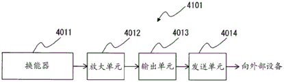
45. An apparatus, comprising: the transducer according to any one of the above 33 to 44, an amplifying means for amplifying an electric signal output from the transducer according to an applied pressure, and an output means for outputting the electric signal amplified by the amplifying means.
46. The device according to 45 above, further comprising a transmission unit that transmits the electric signal output from the output unit to an external device.
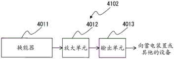
47. An apparatus, comprising: the transducer according to any one of the above 33 to 44, an output unit that outputs an electrical signal from the transducer according to an applied pressure, and a transmission unit that transmits the electrical signal output from the output unit to an external device.
48. An apparatus, comprising: a receiving unit that receives an electrical signal, and a transducer according to any of the above 33-44 to which the electrical signal received by the receiving unit is applied.
The present inventors have intensively studied to achieve the fifth object and found that a combined arrangement of a conductive fiber and a piezoelectric fiber functions as a piezoelectric element, and that a transducer which is hard to malfunction and has high practicability can be provided by laminating a conductive sheet or a conductive fabric on the piezoelectric element, and completed the present invention.
That is, according to the present invention, as means for achieving the fifth object (fifth invention), the following 49 to 64 are provided.
49. A laminated transducer comprising at least 2 layers of a sheet or a fabric, wherein at least 1 layer of the sheet or the fabric comprises the following A layer, and at least 1 layer of the layers other than the A layer comprises the following B layer:
layer A: a transducer including a piezoelectric unit in which a conductive fiber and a piezoelectric fiber are arranged on substantially the same plane so as to provide electrical connection, and which outputs or inputs an electrical signal;
layer B: the sheet resistance is 104 omega/□ (omega/sq.) or less.
50. The transducer according to 49 above, wherein the following C layers are further stacked between the a layer and the B layer:
layer C: an insulating sheet or insulating fabric having a sheet resistance of 106 Ω/□ (Ω/Sq) or more.
51. The transducer according to 49 or 50, wherein the piezoelectric unit includes 2 conductive fibers and 1 piezoelectric fiber, and the conductive fibers, the piezoelectric fibers, and the conductive fibers are arranged in this order.
52. The transducer of 49 or 50, wherein the conductive fibers and the piezoelectric fibers have contacts that physically interface with each other.
53. The transducer according to 49 or 50, wherein an insulating fiber is disposed so that the conductive fiber in the piezoelectric unit is not electrically connected to a conductive fiber and/or a piezoelectric fiber in another piezoelectric unit.
54. The transducer of 49 or 50, wherein the piezoelectric fibers comprise predominantly polylactic acid.
55. The transducer according to 49 or 50, wherein the piezoelectric fiber mainly contains poly-L-lactic acid or poly-D-lactic acid having an optical purity of 99% or more.
56. The transducer of 49 or 50 above, wherein the piezoelectric fibers are uniaxially oriented and comprise crystals.
57. The transducer of 49 or 50, wherein the conductive fibers are metal plated fibers.
58. The transducer according to 49 or 50, wherein the transducer is a woven knitted fabric comprising a plurality of said piezoelectric units.
59. The transducer according to 58, wherein the piezoelectric element is a woven fabric including a plurality of the piezoelectric elements, and the woven fabric is a plain weave, a twill weave, a satin weave, or a composite weave thereof.
60. The transducer according to 59 above, wherein a plurality of the woven fabrics are used in combination.
61. An apparatus, comprising: the transducer according to any one of the above 49 to 60, an amplifying unit that amplifies an electric signal output from the transducer according to an applied pressure, and an output unit that outputs the electric signal amplified by the amplifying unit.
62. The device according to 61, further comprising a transmission unit that transmits the electric signal output from the output unit to an external device.
63. An apparatus, comprising: the transducer according to any of the above 49-60, an output unit that outputs an electrical signal from the transducer according to an applied pressure, and a transmission unit that transmits the electrical signal output from the output unit to an external device.
64. An apparatus, comprising: a receiving unit that receives an electrical signal, and a transducer according to any of the above 49-60 to which the electrical signal received by the receiving unit is applied.
Effects of the invention
With the first invention, a fibrous piezoelectric element capable of extracting an electric output by rubbing a surface with a finger or the like with a relatively small applied stress can be obtained. Further, a fibrous piezoelectric element that can withstand repeated rubbing against the surface or the distal end portion of the piezoelectric element can be obtained.
Further, according to the second invention, it is possible to provide a fibrous piezoelectric element capable of extracting a large electric signal even when a stress due to a relatively small deformation is used.
Further, according to the third aspect of the present invention, it is possible to provide a fibrous piezoelectric element that can extract a large electric signal and suppress a noise signal even when stress due to relatively small deformation is used.
In addition, according to the fourth aspect of the present invention, a fabric-like transducer having high flexibility can be obtained by using a fiber material and by fabricating a conventional woven/knitted fabric structure. The transducer of the present invention is flexible, and therefore, can realize a transducer which can be realized in all shapes that can be realized by a fabric, such as a foldable fabric like a handkerchief, and further, a clothing shape, and the like, and which outputs and inputs an electric signal.
Further, according to the fifth aspect of the present invention, a fabric-like transducer having high flexibility can be obtained by using a fiber material and by fabricating a conventional woven/knitted fabric structure. The transducer of the present invention is flexible, and therefore, can realize a transducer which can be realized in all shapes that can be realized by a fabric, such as a foldable fabric like a handkerchief, and further, a clothing shape, and the like, and which outputs and inputs an electric signal.
Drawings
Fig. 1 is a schematic cross-sectional view illustrating a principle of generation of an electric signal in a combination of a conductive fiber and a piezoelectric fiber.
Fig. 2 is a schematic view of the piezoelectric element described in embodiment 1, which is an example of the structure of the piezoelectric element according to the first invention.
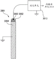
Fig. 3 is a schematic diagram of an evaluation system for a piezoelectric element of example 1.
Fig. 4 is a block diagram showing a sensor provided with the piezoelectric element of the first invention.
Fig. 5 is a schematic diagram showing an example of connection between a piezoelectric element and an amplifying means in a sensor provided with the piezoelectric element according to the first aspect of the present invention.
Fig. 6 is a schematic diagram showing a configuration example of the string-shaped piezoelectric element according to the second invention.
Fig. 7 is a schematic diagram showing a structural example of a fabric-like piezoelectric element according to a second embodiment.
Fig. 8 is a block diagram showing an apparatus provided with the piezoelectric element of the second invention.
Fig. 9 is a schematic diagram showing a configuration example of a device including a fabric-like piezoelectric element according to a second embodiment.
Fig. 10 is a schematic diagram showing another configuration example of an apparatus including the fabric-like piezoelectric element according to the second invention.
Fig. 11 is a schematic diagram showing a structural example of a woven fabric including piezoelectric fibers of comparative example 1.
Fig. 12 is a schematic diagram showing a configuration example of the string-shaped piezoelectric element according to the third invention.
Fig. 13 is a schematic diagram showing a structural example of a fabric-like piezoelectric element according to a third embodiment of the present invention.
Fig. 14 is a block diagram showing an apparatus provided with the piezoelectric element of the third invention.
Fig. 15 is a schematic diagram showing a configuration example of an apparatus including the string-shaped piezoelectric element according to the third aspect of the present invention.
Fig. 16 is a schematic diagram showing a configuration example of a device including the fabric-like piezoelectric element according to the third embodiment.
Fig. 17 is a schematic diagram showing another configuration example of an apparatus including the fabric-like piezoelectric element according to the third aspect of the present invention.
Fig. 18 is a schematic diagram showing another configuration example of an apparatus including the fabric-like piezoelectric element according to the third aspect of the present invention.
Fig. 19 is a schematic diagram showing a structural example of a woven fabric including piezoelectric fibers of comparative example 3.
Fig. 20 shows a structure in which bending in a specific direction is selectively detected in the woven tissue of the layer a.
Fig. 21 is a configuration in which twisting is selectively detected in the woven tissue of the a layer.
Fig. 22 shows a structure in which shear deformation (shearing deformation) is selectively detected in the woven structure of the layer a.
Fig. 23 is a schematic diagram of a sensor laminated with plain weave fabric (plain weave fabric).
Fig. 24 is a schematic diagram of a sensor in which a plain weave fabric and a satin weave fabric (stain) are laminated.
Fig. 25 is a schematic diagram of a sensor in which a satin weave and a capacitance type expansion sensor are laminated.
Fig. 26 is a block diagram showing a first specific example of an apparatus using the transducer (transducer) of the fourth invention.
Fig. 27 is a block diagram showing a second specific example of an apparatus using the transducer of the fourth invention.
Fig. 28 is a block diagram showing a third specific example of an apparatus using the transducer of the fourth invention.
Fig. 29 is a schematic view of plain woven fabrics of example 7 and comparative example 4.
Fig. 30 is a block diagram showing a first specific example of an apparatus using the transducer of the fifth invention.
Fig. 31 is a block diagram showing a second specific example of an apparatus using the transducer of the fifth invention.
Fig. 32 is a block diagram showing a third specific example of an apparatus using the transducer of the fifth invention.
Fig. 33 is a diagram showing an apparatus for measuring the bend recovery rate.
Fig. 34 is a schematic diagram showing a structural example of a fabric-like piezoelectric element.
Fig. 35 is a schematic diagram showing a configuration example of a device provided with a fabric-like piezoelectric element.
Fig. 36 is a block diagram showing a device including the fabric element of the embodiment.
Fig. 37 is a schematic diagram showing a configuration example of the flat wire rope-shaped piezoelectric element according to the embodiment.
Detailed Description
First, a principle of generation of an electric signal in a combination of a conductive fiber and a piezoelectric fiber, which is common to the first to fifth inventions, will be described.
Fig. 1 is a schematic cross-sectional view illustrating a principle of generation of an electric signal in a combination of a conductive fiber and a piezoelectric fiber. The lead wire from the conductive fiber B is connected to the input terminal of the amplification unit 12. In fig. 1 (a), in a state where the conductive fiber B and the piezoelectric fiber a are stretched without being bent, positive and negative charges are uniformly distributed in the conductive fiber B and the piezoelectric fiber a. When the bending of the piezoelectric fiber a is started, polarization occurs in the piezoelectric fiber a as shown in fig. 1 (B), and the positive and negative charges are aligned in one direction. The negative electric charges flow out from the conductive fibers B along with the arrangement of the positive and negative electric charges generated by the polarization of the piezoelectric fibers a. The movement of the negative electric charge appears as a flow of a minute electric signal (i.e., a current), the amplifying unit 12 amplifies the electric signal, and the output unit 13 outputs the electric signal amplified by the amplifying unit 12. The polarization state shown in fig. 1B continues as long as the bending of the piezoelectric fiber a is maintained (fixed).
When the operation of stretching the piezoelectric fiber a is started from a state in which the folded shape of the piezoelectric fiber a is maintained (fixed) (fig. 1B), the polarization is released in the piezoelectric fiber a, and the positive and negative charges are uniformly distributed in the piezoelectric fiber a, as shown in fig. 1C. With the uniform distribution of positive and negative charges in the piezoelectric fibers a, negative charges flow into the conductive fibers B. This movement of the negative electric charge appears as a flow of a minute electric signal (i.e., a current), and the electric signal is amplified by the amplifying means 12 and then output to the output means 13. In the state in which the piezoelectric fiber a is being bent (fig. 1B) and in the state in which the operation is being changed from the bending operation to the stretching operation (fig. 1C), the directions of movement of the negative charges are opposite, and therefore, electric signals of opposite polarities are generated in the bending operation and the stretching operation. For example, a positive electrical signal is generated during the bending operation of the piezoelectric fiber a, and a negative electrical signal is generated during the stretching operation of the piezoelectric fiber a.
In the present invention, a minute electric signal generated in association with the bending operation and the stretching operation of the piezoelectric fiber a is amplified by the amplifying means 12 and output by the output means 12, and the presence or absence of bending and the degree of bending of the piezoelectric fiber a are detected by dividing and opening the large electric signal to positive or negative by arithmetic processing in an external device (not shown). For example, in an external device (not shown), the following arithmetic processing can be executed: the amplified electric signal amplified by the amplifying means 12 and output from the output means 13 is time-integrated, and then determined as "bending operation" when the integrated value is equal to or greater than a predetermined upper limit value, and determined as "stretching operation" when the integrated value is less than a predetermined lower limit value. In the present specification, the description of generating an electrical signal according to stress applied to the piezoelectric fiber a is synonymous with generating an electrical signal according to deformation of the piezoelectric fiber a.
The first invention will be described in detail below.
(coated fiber)
The piezoelectric element according to the first aspect of the invention includes a coating fiber in which the surface of a conductive fiber is coated with a piezoelectric fiber that is a piezoelectric polymer fiber. Fig. 2 is a schematic diagram showing an example of the structure of the piezoelectric element according to the first embodiment of the present invention. As shown in fig. 2, the piezoelectric fibers 100A of the covering fibers 1003 of the piezoelectric element cover the surfaces of the conductive fibers 100B.
The length of the covering fiber 1003 of the piezoelectric element is not particularly limited, but may be continuously manufactured during manufacturing and then cut into a desired length for use. In practical use as a piezoelectric element, the coated fiber 1003 has a length of 1mm to 10m, preferably 5mm to 2m, and more preferably 1cm to 1 m. When the length is short, the convenience as a fiber shape is lost, and when the length is long, there is a problem such as a decrease in electric output due to a problem of the resistance value of the conductive fiber 100B.
(conductive fiber)
As the conductive fiber, any known conductive fiber may be used as long as it shows conductivity, and examples thereof include: metal fibers, fibers made of a conductive polymer, carbon fibers, fibers made of a polymer in which a fibrous or granular conductive filler (filler) is dispersed, or fibers in which a conductive layer is provided on the surface of a fibrous material. Examples of a method for providing a layer having conductivity on the surface of a fibrous material include: metal coating, conductive polymer coating, winding of conductive fibers, and the like. Among them, metal coating is also preferable from the viewpoint of conductivity, durability, flexibility, and the like. Specific examples of the method for coating the metal include vapor deposition, sputtering, electrolytic plating, and electroless plating, but plating is preferred from the viewpoint of productivity and the like. Such metal-plated fibers can be referred to as metal-plated fibers.
As the fibers of the metal-coated substrate, known fibers can be used regardless of the presence or absence of conductivity, and examples thereof include synthetic fibers such as polyester fibers, nylon fibers, acrylic (acryl) fibers, polyethylene fibers, polypropylene fibers, vinyl chloride fibers, aramid fibers, polysulfone (polysulfone) fibers, polyether (polyether) fibers, and polyurethane (polyurethane) fibers, and also natural fibers such as cotton, hemp fibers, and silk, semisynthetic fibers such as acetate (acetate), rayon fibers, and regenerated fibers such as cuprammonium fibers. The base fiber is not limited to these, and any known fiber may be used, and these fibers may be used in combination.
The metal coated on the fibers of the substrate shows conductivity, and any metal may be used as long as the effect of the present invention is obtained. For example, gold, silver, platinum, copper, nickel, tin, zinc, palladium, copper sulfide, or the like, and a mixture or an alloy thereof, or the like can be used.
When an organic fiber coated with a metal having flexibility resistance is used for the conductive fiber, the conductive fiber is very rarely broken, and the sensor using the piezoelectric element is excellent in durability and safety.
As the conductive fiber, a multifilament formed by bundling a plurality of filaments may be used, and a monofilament formed by 1 filament may be used. From the viewpoint of long-term stability of electrical characteristics, the multifilament is more preferably used. The monofilament has a diameter of 1 to 5000 μm, preferably 2 to 100 μm. More preferably 3 to 50 μm. The number of the fiber filaments is preferably 1 to 100000, more preferably 5 to 500, and still more preferably 10 to 100.
When the diameter is small, the strength is reduced, handling becomes difficult, and further, in the case of a large diameter, flexibility becomes a sacrifice. The cross-sectional shape of the conductive fiber is preferably a circle or an ellipse from the viewpoint of design and manufacture of the piezoelectric element, but is not limited thereto.
In addition, in order to efficiently extract the electrical output from the piezoelectric polymer, the resistance is preferably low, and the volume resistivity is preferably highIs selected from 10-1Omega cm or less, more preferably 10-2Omega cm or less, and more preferably 10-3Omega cm or less. However, the resistivity of the conductive fiber is not limited to this as long as the intensity is obtained in the signal detection.
The conductive fiber is required to have resistance to repeated bending, twisting, and other motions in view of the use of the present invention. As an index thereof, the bending rigidity is preferably smaller. In general, the flexural rigidity is measured by a measuring apparatus such as KES-FB2 pure bending tester manufactured by keskato. The degree of bending rigidity suitable in the present invention is preferably smaller than the product "HTS 403K" which is a carbon fiber multifilament yarn made of eastern tenax (stock). Specifically, the bending rigidity of the conductive fiber is preferably 0.05 × 10⁻⁴N·m2A value of less than or equal to m, more preferably 0.02X 10⁻⁴N·m2A value of 0.01X 10 or less, preferably- 4N·m2And/m is less than or equal to.
(piezoelectric Polymer)
As the piezoelectric polymer, any polymer having piezoelectric properties such as polyvinylidene fluoride (pvdf) and polylactic acid can be used, but preferably, polylactic acid is mainly contained. Polylactic acid is superior in productivity because it shows piezoelectricity by being easily oriented by stretching after melt spinning and does not require an electric field orientation treatment which is required in polyvinylidene fluoride or the like. Further, the piezoelectric fibers are formed of a piezoelectric polymer, but the piezoelectric fibers made of polylactic acid have small polarization due to tensile or compressive stress in the axial direction thereof and hardly function as a piezoelectric element, but obtain a relatively large electric output by shear stress (shearing stress), and are preferable for the piezoelectric element of the present invention having a structure that easily gives shear stress to the piezoelectric polymer.
The piezoelectric polymer preferably mainly contains polylactic acid. "mainly" means preferably 90 mol% or more, more preferably 95 mol% or more, and further preferably 98 mol% or more.
As polylactic acid, there are poly-L-lactic acid obtained by polymerizing L-lactic acid and L-lactide, poly-D-lactic acid obtained by polymerizing D-lactic acid and D-lactide, and stereocomplex polylactic acid having a mixed structure of these, depending on the crystal structure thereof. From the viewpoint of high or low piezoelectric coefficient, poly-L-lactic acid and poly-D-lactic acid are preferred. Since poly-L-lactic acid and poly-D-lactic acid have opposite polarizations for the same stress, they can be used in combination according to the purpose. The optical purity of the polylactic acid is preferably 99% or more, more preferably 99.3% or more, and still more preferably 99.5% or more. If the optical purity is less than 99%, the piezoelectric coefficient may be significantly reduced, and it may be difficult to obtain a sufficient electric output by changing the shape of the piezoelectric fiber. The piezoelectric polymer mainly contains poly-L-lactic acid or poly-D-lactic acid, and the optical purity thereof is preferably 99% or more.
The piezoelectric fiber formed of a piezoelectric polymer is preferably a fiber that is uniaxially oriented in the fiber axis direction of the covering fiber and contains a crystal, and more preferably a uniaxially oriented polylactic acid having a crystal. The reason is because polylactic acid shows large piezoelectricity in its crystalline state and uniaxial orientation.
Since polylactic acid is a polyester that is relatively rapidly hydrolyzed, a publicly known hydrolysis inhibitor such as an isocyanate compound, an oxazoline compound, an epoxy compound, or a carbodiimide compound may be added when the moist heat resistance is a problem. Further, an antioxidant such as a phosphoric acid compound, a plasticizer, an anti-photodegradation agent, and the like may be added as necessary to improve physical properties.
Further, polylactic acid may be used as an alloy with other polymers, but if polylactic acid is used as a main piezoelectric polymer, it is preferable to contain polylactic acid in an amount of at least 50% by weight, more preferably 70% by weight or more, and most preferably 90% by weight or more, based on the total weight of the alloy.
As the polymer other than polylactic acid in the case of forming an alloy, polybutylene terephthalate, polyethylene naphthalate copolymer, polymethacrylate (polymethacrylate) and the like are preferable examples, but the polymer is not limited to these, and any polymer may be used as long as it has piezoelectric properties intended in the present invention.
In order to form such a piezoelectric polymer into a piezoelectric fiber, any known method for fibrillating a polymer can be used as long as the effect of the present invention is achieved, and a method of fibrillating a piezoelectric polymer by extrusion molding, a method of fibrillating a piezoelectric polymer by melt spinning, a method of fibrillating a piezoelectric polymer by dry or wet spinning, a method of fibrillating a piezoelectric polymer by electrospinning, and the like can be used. These spinning conditions may be any known method depending on the piezoelectric polymer to be used, and usually a melt spinning method which is industrially easy to produce is used.
Further, as described above, when the piezoelectric polymer is polylactic acid, the fiber is preferably stretched because it shows a larger piezoelectric property when it is uniaxially stretched and contains crystals.
(coating)
The surface of each conductive fiber is coated with a piezoelectric fiber made of a piezoelectric polymer. The thickness of the piezoelectric fiber layer covering the conductive fibers is preferably 1 μm to 10mm, more preferably 5 μm to 5mm, still more preferably 10 μm to 3mm, and most preferably 20 μm to 1 mm. If the thickness is too thin, it may cause a problem in terms of strength, and if it is too thick, it may be difficult to extract an electric output.
Although it is preferable that the piezoelectric fibers and the conductive fibers are in close contact with each other as much as possible, an anchor layer, an adhesive layer, or the like may be provided between the conductive fibers and the piezoelectric fibers in order to improve the close contact.
The coating method is a method in which a piezoelectric fiber is wound around a conductive fiber. On the other hand, the shape of the piezoelectric fiber layer is not particularly limited as long as it can generate an electric output against the applied stress.
The conductive fibers of the piezoelectric polymer are in a coated state, but the shapes of the conductive fibers and the piezoelectric fibers are not particularly limited, and preferably as close to concentric circles as possible. When a multifilament is used as the conductive fiber, the piezoelectric fiber may be coated on the surface (fiber circumferential surface) of the multifilament as long as the piezoelectric fiber is in contact with at least a part of the surface (fiber circumferential surface) of the multifilament, or the piezoelectric fiber may not be coated on the surface (fiber circumferential surface) of the multifilament. The coating state of the piezoelectric fibers of each fiber filament inside the multifilament constituting the conductive fiber may be appropriately set in consideration of the performance, operability, and the like of the piezoelectric element.
The piezoelectric element of the present invention includes at least 1 conductive fiber, but the number of conductive fibers is not limited to 1, and may be more.
The piezoelectric element of the present invention does not require an electrode on the surface thereof, and therefore, there is no need to further cover the piezoelectric element itself, and there is an advantage that malfunction is difficult.
(production method)
The piezoelectric element of the present invention includes a coating fiber in which the surface of 1 conductive fiber is coated with a piezoelectric fiber. The following methods can be mentioned as methods for producing the coated fiber.
(i) Preferably, the conductive fiber and the piezoelectric fiber after stretching are prepared in separate steps, and the piezoelectric fiber is wrapped by winding the conductive fiber or the like. In this case, the coating is preferably formed in a manner as close to concentric circles as possible.
In this case, as preferable spinning and drawing conditions in the case where polylactic acid is used as the piezoelectric polymer for forming the piezoelectric fibers, the melt spinning temperature is preferably 150 to 250 ℃, the drawing temperature is preferably 40 to 150 ℃, the draw ratio is preferably 1.1 to 5.0 times, and the crystallization temperature is preferably 80 to 170 ℃.
As the wound piezoelectric fiber, a multifilament obtained by bundling a plurality of fibers may be used, or a monofilament may be used.
The winding and coating may be performed, for example, by forming the piezoelectric fiber into a braided tube and inserting the conductive fiber as a core into the braided tube. Further, a Tubular Braid (Tubular Braid) may be produced by forming a core of conductive fibers and stranding piezoelectric fibers around the core to coat the core. When the piezoelectric fiber is used as a monofilament, the single thread diameter is 1 μm to 5mm, preferably 5 μm to 2mm, and more preferably 10 μm to 1 mm. When used as a multifilament, the single yarn diameter is 0.1 to 5mm, preferably 2 to 100 μm, and more preferably 3 to 50 μm. The number of the multifilament is preferably 1 to 100000, more preferably 50 to 50000, and still more preferably 100 to 20000.
The piezoelectric element of the present invention can be obtained by using a fiber produced by the above-described method, in which the surface of the conductive fiber is coated with a piezoelectric fiber.
The piezoelectric element of the present invention can be manufactured relatively easily because it does not require a conductive layer to be formed on the surface.
(protective layer)
A protective layer may also be provided on the outermost surface of the piezoelectric element of the present invention. The protective layer is preferably insulating, and is more preferably made of a polymer from the viewpoint of flexibility and the like. In this case, of course, friction is applied to the protective layer, but there is no particular limitation as long as the shear stress generated by the friction reaches the piezoelectric fibers and can cause polarization thereof. The protective layer is not limited to a protective layer formed by coating with a polymer or the like, and may be a thin film or the like or a protective layer combining these. As the protective layer, epoxy resin, acrylic resin, or the like is preferably used.
The thickness of the protective layer is preferably 10nm to 200 μm, more preferably 50nm to 50 μm, even more preferably 70nm to 30 μm, and most preferably 100nm to 10 μm, because the problem of the protective layer itself being broken is likely to occur when the protective layer is too thin. The shape of the piezoelectric element can also be formed by the protective layer.
(action)
The piezoelectric element of the present invention can be used as a sensor for detecting the magnitude and/or position of stress applied to the piezoelectric element by rubbing the surface of the piezoelectric element or the like. In the piezoelectric element of the present invention, it is needless to say that an electric output can be obtained if a shear stress is applied to the piezoelectric polymer by a pressing force other than friction. Examples of the "applied stress" include a frictional force between the surface of (the piezoelectric fiber of) the covering fiber, which is the surface of the piezoelectric element, and the surface of a contact object such as a finger, and a resistance force in a direction perpendicular to the surface or the distal end of (the piezoelectric fiber of) the covering fiber. In particular, the piezoelectric element of the present invention is easy to efficiently extract a large electric output in the case of buckling in the parallel direction to the conductive fiber or in the case of friction.
Here, "applied stress" means a stress of a magnitude of a degree of rubbing a surface with a finger, and the target of the stress of the magnitude of the degree of rubbing the surface with the finger is approximately 1 to 1000 Pa. Of course, even if this is done, the magnitude of the applied stress and the applied position thereof can be detected. When an input is made with a finger or the like, it is preferable that the operation is performed even under a load of 1Pa to 500Pa, and more preferably, it is preferable that the operation is performed under a load of 1Pa to 100 Pa. Of course, as described above, the operation is performed even with a load exceeding 500 Pa.
(multiple piezoelectric elements)
In addition, a plurality of piezoelectric elements of the present invention may be arranged and used. As an arrangement method, the yarn may be arranged one-dimensionally in one stage or two-dimensionally in a superposed manner, and may be used by weaving a woven fabric or by making a rope into a string. This also enables the realization of a cloth-like or string-like piezoelectric element. When the fabric or the string is formed, the fabric or the string may be combined with other fibers than the piezoelectric element to perform fiber mixing, blending (mixed weave), mixed knitting (mixed knitting), or the like, or may be used as a resin incorporated in a housing of a smartphone, or the like, as long as the object of the present invention is achieved.
When a plurality of piezoelectric elements of the present invention are used in an array as described above, the piezoelectric elements of the present invention do not have electrodes on the surface, and therefore, there is an advantage that the array method and the knitting method can be widely selected.
When a plurality of piezoelectric elements of the present invention are used in an array, the distance between the conductive fibers is short, and therefore, the piezoelectric elements are highly efficient in extracting electric output. Further, by keeping the distance between the conductive fibers constant, variation in location according to the electric output can be suppressed.
(insulating fiber)
In the present invention, for example, an insulating fiber can be used for a portion other than the covering fiber in the piezoelectric element. In this case, the insulating fiber can be made of a material or a shape having elasticity for the purpose of improving the flexibility of the piezoelectric element.
By disposing the insulating fiber in the manner described above in the region other than the covering fiber portion, the performance as the operability of the piezoelectric element (for example, the assistance of the operation of the contact probe using the piezoelectric element) can be improved.
Such an insulating fiber is not particularly limited as long as it has a volume resistivity of 106Can be used when the concentration is not less than Ω · cm, and is more preferably 10 8Omega cm or more, and more preferably 1010Omega cm or more.
Examples of the insulating fibers include synthetic fibers such as polyester fibers, nylon fibers, acrylic fibers, polyethylene fibers, polypropylene fibers, vinyl chloride fibers, aramid fibers, polysulfone fibers, polyether fibers, and polyurethane fibers, natural fibers such as cotton, hemp fibers and silk, semisynthetic fibers such as acetate fibers, rayon fibers, and regenerated fibers such as cuprammonium fibers. The insulating fiber is not limited to these, and known insulating fibers can be used arbitrarily. Further, these insulating fibers may be used in combination, or a fiber having an insulating property as a whole may be used in combination with a fiber having no insulating property.
In addition, fibers of all known shapes can be used for the purpose of flexibility.
(technique of applying piezoelectric element)
In any case of the piezoelectric elements of the present invention, since the contact, pressure, and shape change to the surface can be output as an electric signal, the piezoelectric element can be used as a sensor for detecting the magnitude and/or position of the stress applied to the piezoelectric element. Fig. 4 is a block diagram showing a sensor provided with a piezoelectric element of the present invention. If the sensor 1101 including the piezoelectric element 1011 of the present invention, the amplifying means 1012 for amplifying the electric signal output from the piezoelectric element 1011 in accordance with the applied stress, the output means 1013 for outputting the electric signal amplified by the amplifying means 1012, and the transmitting means 1014 for transmitting the electric signal output from the output means 1013 to an external device (not shown) is configured, the magnitude and/or the position of the applied stress to the piezoelectric element 1011 can be detected by an arithmetic processing in the external device (not shown) based on the electric signal output in accordance with the contact, the pressure, and the change in the shape to the surface of the piezoelectric element 1011. Alternatively, an arithmetic unit (not shown) for calculating the magnitude of the stress applied to the piezoelectric element 1011 and/or the position of the stress applied thereto based on the electric signal output from the output unit 1013 may be provided in the sensor 1101.
The amplifying unit 1012 may be configured by various electronic circuits, a functional module installed by a software program that operates on a processor, or a combination of various electronic circuits and software programs, for example. Examples of the processor include a CPU (Central Processing Unit), a DSP (digital signal processor), an LSI (large scale integration), an ASIC (Application Specific Integrated Circuit), an FPGA (Field programmable Gate Array), and the like. The output unit 1013 may be configured by a single connector or may be configured as a communication device integrated with the transmission unit 2014. Alternatively, the present invention may be implemented by an integrated circuit, a microprocessor, or the like that integrates the functions of the amplification unit 1012, the output unit 1013, and the transmission unit 1014 and writes a software program. The transmission method by the transmission unit 1014 may be determined appropriately according to the sensor configuration, and may be a wireless method or a wired method. In addition, the contact probe can also be realized using the same structure as the sensor described above.
In addition, not only the amplifier unit but also a known signal processing unit such as a unit for removing noise or a unit for processing by combining with another signal can be used. The order of connection of these units can be appropriately changed according to the purpose. Of course, the electric signal output from the pressure element 1011 may be directly transmitted to an external device and then subjected to signal processing.
Fig. 5 is a schematic diagram showing an example of connection between a piezoelectric element and an amplifying means in a sensor provided with the piezoelectric element according to the first aspect of the present invention. Although amplifying section 1012 in fig. 5 corresponds to the section described with reference to fig. 4, output section 1013 and transmission section 1014 in fig. 4 are not shown in fig. 5. In the case of configuring a sensor including the piezoelectric element 1011, for example, a lead wire of the conductive fiber 100B from the piezoelectric element 1011 is connected to an input terminal of the amplifying unit 1012, and the piezoelectric fiber 100A is connected to a ground (earth) terminal.
Hereinafter, the second invention will be described in detail.
(wire-shaped piezoelectric element)
Fig. 6 is a schematic diagram showing a configuration example of the string-shaped piezoelectric element according to the second invention.
The string-shaped piezoelectric element 2001 includes: a core 2003 formed of conductive fibers 200B, and a sheath 2002 formed of a piezoelectric fiber 200A in a string shape so as to cover the core 2003. The piezoelectric fiber 200A may contain polylactic acid as a main component. The winding angle α of the piezoelectric fiber 200A with respect to the conductive fiber 200B is 15 ° or more and 75 ° or less.
In the string-shaped piezoelectric element 2001, the plurality of piezoelectric fibers a densely surround the outer peripheral surface of at least one conductive fiber 200B. While not being bound by any particular theory, when the string-shaped piezoelectric element 2001 is deformed, stress due to the deformation is generated in each of the plurality of piezoelectric fibers 200A, and thereby an electric field is generated in each of the plurality of piezoelectric fibers 200A (piezoelectric effect), and as a result, it is estimated that: a voltage change is generated in the conductive fiber 200B by superimposing the electric field of the piezoelectric fibers 200A surrounding the conductive fiber 200B. That is, the electrical signal from the conductive fiber 200B is increased as compared with the case where the sheath 2002 in the string shape of the piezoelectric fiber 200A is not used. Thus, even in the string-shaped piezoelectric element 2001, a large electric signal can be extracted by using stress generated by relatively small deformation. Further, a plurality of conductive fibers 200B may be provided.
Here, the piezoelectric fiber 200A preferably contains polylactic acid as a main component. "as a main component" means that the most abundant component among the components of the piezoelectric fiber 200A is polylactic acid. The lactic acid unit in the polylactic acid is preferably 90 mol% or more, more preferably 95 mol% or more, and still more preferably 98 mol% or more.
The winding angle α of the piezoelectric fiber 200A with respect to the conductive fiber 200B is 15 ° or more and 75 ° or less. That is, the winding angle α of the piezoelectric fiber 200A is 15 ° or more and 75 ° or less with respect to the direction of the center axis CL of the conductive fiber 200B (core 2003). However, in the present embodiment, the center axis CL of the conductive fiber 200B overlaps the center axis of the cord (sheath 2002) of the piezoelectric fiber 200A (hereinafter, also referred to as "cord axis"), and therefore, may be referred to as: the winding angle α of the piezoelectric fiber 200A is 15 ° or more and 75 ° or less with respect to the direction of the cord axis of the piezoelectric fiber 200A. From the viewpoint of taking out a larger electric signal, the angle α is preferably 25 ° or more and 65 ° or less, more preferably 35 ° or more and 55 ° or less, and further preferably 40 ° or more and 50 ° or less. This is because, when the angle α deviates from this angle range, the electric field generated in the piezoelectric fiber 200A is significantly reduced, and thus the electric signal obtained by the conductive fiber 200B is significantly reduced.
The angle α may be also referred to as an angle formed by the main direction of the piezoelectric fiber 200A forming the sheath 2002 and the center axis CL of the conductive fiber 200B, and a part of the piezoelectric fiber 200A may be loosened or fluffed.
Here, the reason why the electric field generated in the piezoelectric fiber 200A is significantly reduced is as follows. The piezoelectric fiber 200A is uniaxially oriented in the fiber axis direction of the piezoelectric fiber 200A, with polylactic acid as a main component. Here, although an electric field is generated when shear stress (compressive stress) is generated in the orientation direction (in this case, the direction of the fiber axis of the piezoelectric fiber 200A), an electric field is not generated much when tensile stress or compressive stress is generated in the orientation direction. Therefore, it is presumed that: in order to generate shear stress in the piezoelectric fibers 200A when the deformation is performed in parallel to the direction of the string axis, the orientation direction of the piezoelectric fibers 200A (polylactic acid) may be in a predetermined angle range with respect to the string axis.
In the wire-shaped piezoelectric element 2001, as long as the object of the present invention is achieved, the sheath portion 2002 may be combined with other fibers than the piezoelectric fibers 200A to perform fiber mixing, or the core portion 2003 may be combined with other fibers than the conductive fibers 200B to perform fiber mixing.
The length of the wire-shaped piezoelectric element formed of the core 2003 of the conductive fiber 200B and the sheath 2002 of the wire-shaped piezoelectric fiber 200A is not particularly limited. For example, the string-shaped piezoelectric element may be continuously manufactured in manufacturing and then cut into a desired length for use. The length of the string-shaped piezoelectric element is 1mm to 10m, preferably 5mm to 2m, and more preferably 1cm to 1 m. When the length is too short, convenience as a fiber shape is lost, and when the length is too long, there arises a need to consider the resistance value of the conductive fiber 200B.
Hereinafter, each configuration will be described in detail.
(conductive fiber)
As the conductive fiber 200B, any known conductive fiber may be used as long as it shows conductivity. Examples of the conductive fiber 200B include: metal fibers, fibers made of a conductive polymer, carbon fibers, fibers made of a polymer in which a fibrous or granular conductive filler (filler) is dispersed, or fibers in which a conductive layer is provided on the surface of a fibrous material. Examples of a method for providing a layer having conductivity on the surface of a fibrous material include: metal coating, conductive polymer coating, winding of conductive fibers, and the like. Among them, metal coating is also preferable from the viewpoint of conductivity, durability, flexibility, and the like. Specific examples of the method for coating the metal include vapor deposition, sputtering, electrolytic plating, and electroless plating, but plating is preferred from the viewpoint of productivity and the like. Such metal-plated fibers can be referred to as metal-plated fibers.
As the fibers of the metal-coated substrate, known fibers can be used regardless of the presence or absence of conductivity, and examples thereof include synthetic fibers such as polyester fibers, nylon fibers, acrylic (acryl) fibers, polyethylene fibers, polypropylene fibers, vinyl chloride fibers, aramid fibers, polysulfone (polysulfone) fibers, polyether (polyether) fibers, and polyurethane (polyurethane) fibers, and also natural fibers such as cotton, hemp fibers, and silk, semisynthetic fibers such as acetate (acetate), rayon fibers, and regenerated fibers such as cuprammonium fibers. The base fiber is not limited to these, and any known fiber may be used, and these fibers may be used in combination.
The metal coated on the fibers of the substrate shows conductivity, and any metal may be used as long as the effect of the present invention is obtained. For example, gold, silver, platinum, copper, nickel, tin, zinc, palladium, copper sulfide, or the like, and a mixture or an alloy thereof, or the like can be used.
When the organic fiber coated with the buckling-resistant metal is used for the conductive fiber 200B, the conductive fiber is very rarely broken, and the sensor using the piezoelectric element is excellent in durability and safety.
The conductive fiber 200B may be a multifilament formed by bundling a plurality of fibers, or may be a monofilament formed by 1 fiber. The multifilament is more preferable from the viewpoint of long stability of electrical characteristics. In the case of monofilaments (including yarns), the single-strand diameter thereof is 1 to 5000 μm, preferably 2 to 100 μm. More preferably 3 to 50 μm. In the case of multifilament, the number of filaments is preferably 1 to 100000, more preferably 5 to 500, and still more preferably 10 to 100. However, the fineness and number of the conductive fibers 200B are the fineness and number of the core 2003 used in producing the cord, and it is assumed that the number of multifilaments formed of a plurality of single wires (monofilaments) is also one conductive fiber 200B. Here, the core 2003 is an amount including the entire fiber even when a fiber other than the conductive fiber is used.
When the diameter of the fiber is small, the strength is reduced and handling becomes difficult, and further, when the diameter is large, flexibility becomes a sacrifice. The cross-sectional shape of the conductive fiber 200B is preferably a circle or an ellipse from the viewpoint of design and manufacture of the piezoelectric element, but is not limited thereto.
In addition, in order to efficiently extract the electric output from the piezoelectric polymer, the resistance is preferably low, and the volume resistivity is preferably 10-1Omega cm or less, more preferably 10-2Omega cm or less, and more preferably 10-3Omega cm or less. However, the resistivity of the conductive fiber 200B is not limited to this as long as sufficient strength is obtained in the detection of the electric signal.
The conductive fiber 200B is required to have resistance to repeated bending, twisting, and other movements in view of the application of the present invention. As an index thereof, it is preferable that the nodule strength (knottstrength) is larger. The knot strength can be measured by JIS L1013: 20108.6, respectively. The knot strength suitable for the present invention is preferably 0.5cN/dtex or more, more preferably 1.0cN/dtex or more, still more preferably 1.5cN/dtex or more, and most preferably 2.0cN/dtex or more. As another index, the bending rigidity is preferably smaller. In general, the bending rigidity is measured by a measuring apparatus such as KES-FB2 pure bending tester manufactured by keskato (Co., Ltd.). As appropriate antibodies in the present invention The degree of bending rigidity is preferably smaller than that of carbon fiber "tenax" (registered trademark) HTS40-3K made by eastern tenax (stock). Specifically, the bending rigidity of the conductive fiber is preferably 0.05 × 10⁻⁴N·m2A value of less than or equal to m, more preferably 0.02X 10⁻⁴N·m2A value of 0.01X 10 or less, preferably-4N·m2And/m is less than or equal to.
(piezoelectric fiber)
As the piezoelectric polymer that is the material of the piezoelectric fibers 200A, a polymer exhibiting piezoelectric properties such as polyvinylidene fluoride or polylactic acid can be used, but in the present embodiment, as described above, the piezoelectric fibers 200A preferably contain polylactic acid as a main component. With regard to polylactic acid, productivity is superior in that electric field orientation treatment required in polyvinylidene fluoride or the like is not required since piezoelectricity is exhibited by easily performing orientation by stretching after, for example, melt spinning. However, this is not intended to preclude the use of piezoelectric materials such as polyvinylidene fluoride in the practice of the present invention.
As polylactic acid, there are poly-L-lactic acid obtained by polymerizing L-lactic acid and L-lactide, poly-D-lactic acid obtained by polymerizing D-lactic acid and D-lactide, and stereocomplex polylactic acid having a mixed structure of these, depending on the crystal structure thereof. From the viewpoint of high or low piezoelectric coefficient, poly-L-lactic acid and poly-D-lactic acid are preferred. Since poly-L-lactic acid and poly-D-lactic acid have opposite polarizations for the same stress, they can be used in combination according to the purpose.
The optical purity of the polylactic acid is preferably 99% or more, more preferably 99.3% or more, and still more preferably 99.5% or more. If the optical purity is less than 99%, the piezoelectric coefficient may be significantly reduced, and it may be difficult to obtain a sufficient electric signal by changing the shape of the piezoelectric fiber a. In particular, the piezoelectric fiber a contains poly-L-lactic acid or poly-D-lactic acid as a main component, and it is preferable that the optical purity thereof is 99% or more.
The piezoelectric fiber 200A containing polylactic acid as a main component is stretched during production and uniaxially oriented in the fiber axis direction. Further, the piezoelectric fiber 200A is preferably a fiber containing not only a crystal of polylactic acid but also a fiber uniaxially oriented in the fiber axis direction thereof, and more preferably a fiber containing a crystal of polylactic acid uniaxially oriented. The reason is because polylactic acid shows greater piezoelectricity due to its high crystallinity and uniaxial orientation.
Degree of crystallization X by homogeneous PLAhomoThe crystallinity and uniaxial orientation were determined by (%) and the degree of crystal orientation Ao (%). Homogeneous PLA As the piezoelectric fiber A of the present invention, degree of crystallization Xhomo(%) and the degree of crystal orientation Ao (%) preferably satisfy the following formula (1).

In the case where the above formula (1) is not satisfied, there is a possibility that: the crystallinity and/or uniaxial orientation are insufficient, and the output value of an electric signal for operation decreases or the sensitivity of a signal for operation in a specific direction decreases. The value on the left side of the above formula (1) is more preferably 0.28 or more, and still more preferably 0.3 or more. Here, each value is obtained as follows.
Degree of crystallization X of homogeneous polylactic acidhomo:
Obtaining homogeneous polylactic acid crystallinity X from crystal structure analysis by wide-angle X-ray diffraction analysis (WAXD)homo. In the wide-angle X-ray diffraction analysis (WAXD), an X-ray diffraction pattern of a sample was recorded in an imaging plate (imaging plate) by a transmission method under the following conditions using an X-ray diffraction apparatus model ultrax18, manufactured by Rigaku.
An X-ray source: Cu-Kalpha line (confocal mirror)
And (3) outputting: 45kV x 60mA
Slit: 1 st: 1mm Φ, 2 nd: 0.8mm phi
Length of the camera: 120mm
And (3) accumulating time: 10 minutes
Sample preparation: 35mg of polylactic acid fibers were combined to prepare a 3cm bundle.
The total scattering intensity Itotal is determined over the azimuth angle in the obtained X-ray diffraction pattern, and here the sum Σ I of the integrated intensities of the diffraction peaks originating from the homogeneous polylactic acid crystal appearing in the vicinity of 2 θ =16.5 °, 18.5 °, and 24.3 ° is determined HMi. From these values, the degree of crystallization X of the homogeneous polylactic acid is determined by the following formula (2)homo。

Furthermore, sigma IHMiCalculated by subtracting the background or diffuse reflection caused by amorphization from the total scattered intensity.
(2) Degree of crystal orientation Ao:
regarding the degree of crystal orientation Ao, in the X-ray diffraction pattern obtained by the wide-angle X-ray diffraction analysis (WAXD) described above, an intensity distribution with respect to an azimuth angle (°) is obtained for a diffraction peak derived from a homogeneous polylactic acid crystal appearing in the vicinity of 2 θ =16.5 ° in the radial direction, and the total Σ of the half-height width of the obtained distribution profile (profile) is obtainedwi(°) was calculated from the following formula (3).

Further, since polylactic acid is a polyester which is relatively fast in hydrolysis, when the moist heat resistance is a problem, a publicly known hydrolysis inhibitor such as an isocyanate compound, an oxazoline compound, an epoxy compound, or a carbodiimide compound may be added. Further, an antioxidant such as a phosphoric acid compound, a plasticizer, an anti-photodegradation agent, and the like may be added as necessary to improve physical properties.
Further, polylactic acid may be used as an alloy with other polymers, but if polylactic acid is used as a main piezoelectric polymer, it is preferable to contain polylactic acid at least 50 mass% or more, more preferably 70 mass% or more, and most preferably 90 mass% or more, based on the total mass of the alloy.
The polymer other than polylactic acid in the case of the alloy is preferably exemplified by polybutylene terephthalate, polyethylene naphthalate copolymer, polymethacrylate, and the like, but is not limited thereto, and any polymer may be used as long as it has piezoelectric properties intended in the present invention.
The piezoelectric fiber 200A may be a multifilament formed by bundling a plurality of filaments, or may be a monofilament formed by 1 filament. In the case of monofilaments (including yarns), the single-strand diameter thereof is 1 μm to 5mm, preferably 5 μm to 2mm, and more preferably 10 μm to 1 mm. In the case of multifilament yarn, the single yarn diameter is 0.1 to 5mm, preferably 2 to 100 μm, and more preferably 3 to 50 μm. The number of the multifilament is preferably 1 to 100000, more preferably 50 to 50000, and still more preferably 100 to 20000. However, the fineness and the number of the piezoelectric fibers 200A are the fineness and the number of carriers per 1 carrier when the cord is produced, and it is assumed that the number of the multifilaments formed of a plurality of single wires (monofilaments) is also one piezoelectric fiber 200A. Here, the total amount of the 1 support including the fibers other than the piezoelectric fibers is used.
In order to form the piezoelectric polymer into the piezoelectric fiber 200A, any known method for forming fibers from a polymer can be used as long as the effect of the present invention is obtained. For example, a method of forming fibers by extrusion molding of a piezoelectric polymer, a method of forming fibers by melt spinning of a piezoelectric polymer, a method of forming fibers of a piezoelectric polymer by dry or wet spinning, a method of forming fibers of a piezoelectric polymer by electrostatic spinning, a method of cutting a thin film into fine pieces after forming the thin film, and the like can be employed. These spinning conditions may be any known method depending on the piezoelectric polymer to be used, and usually a melt spinning method which is industrially easy to produce is used. Further, the formed fibers are extended after the fibers are formed. Thereby forming a piezoelectric fiber 200A showing a large piezoelectricity which is uniaxially oriented and contains crystals.
The piezoelectric fiber 200A may be subjected to a treatment such as dyeing, twisting, doubling, heat treatment, or the like before the fiber produced as described above is formed into a string.
Further, since the piezoelectric fibers 200A may be broken or fluffed by friction between the fibers when forming a string, the strength and abrasion resistance thereof are more preferably high, and the strength is preferably 1.5cN/dtex or more, more preferably 2.0cN/dtex or more, further preferably 2.5cN/dtex or more, and most preferably 3.0cN/dtex or more. Can be measured by JIS L1095: 20109.10.2B method, the number of times of rubbing is preferably 100 or more, more preferably 1000 or more, further preferably 5000 or more, and most preferably 10000 or more. The method for improving the abrasion resistance is not particularly limited, and any known method can be used, for example, a method of improving the crystallinity, adding fine particles, or surface-processing. Further, when the cord is processed, the fibers can be coated with a lubricant to reduce friction.
It is preferable that the difference between the shrinkage rate of the piezoelectric fiber and the shrinkage rate of the conductive fiber is small. When the difference in shrinkage is large, the string may be bent or the fabric may be flat or the piezoelectric signal may be weakened when heat is applied or time is changed in a post-treatment step after the string is produced or the fabric is produced or in actual use. When the shrinkage is quantified by the boiling water shrinkage described later, the boiling water shrinkage s (p) of the piezoelectric fiber and the boiling water shrinkage s (c) of the conductive fiber preferably satisfy the following formula (4).

The left side of the above formula (4) is more preferably 5 or less, and even more preferably 3 or less.
It is also preferable that the difference between the shrinkage rate of the piezoelectric fibers and the shrinkage rate of fibers other than the conductive fibers, for example, insulating fibers, is small. When the difference in shrinkage is large, the string may be bent or the fabric may be flat or the piezoelectric signal may be weakened when heat is applied or time is changed in a post-treatment step after the string is produced or the fabric is produced or in actual use. When the shrinkage is quantified by the boiling water shrinkage, the boiling water shrinkage s (p) of the piezoelectric fiber and the boiling water shrinkage s (i) of the insulating fiber preferably satisfy the following formula (5).

The left side of the above formula (5) is more preferably 5 or less, and still more preferably 3 or less.
Further, the piezoelectric fiber preferably has a small shrinkage rate. For example, when the shrinkage is quantified using the shrinkage in boiling water, the shrinkage of the piezoelectric fiber is preferably 15% or less, more preferably 10% or less, even more preferably 5% or less, and most preferably 3% or less. As a method for reducing the shrinkage rate, any known method can be applied, and for example, the shrinkage rate can be reduced by reducing the orientation relaxation or crystallinity of the amorphous portion by heat treatment, and the timing of applying the heat treatment is not particularly limited, and examples thereof include after stretching, after twisting, after forming into a string, after forming into a fabric, and the like. The boiling water shrinkage is measured by the following method. A bobbin was wound 20 times with a measuring machine having a frame circumference of 1.125m, and a load of 0.022cN/dtex was applied to the bobbin, and the bobbin was hung on a scale plate (scale plate) to measure an initial bobbin length L0. After that, the bobbin was treated in a boiling water bath at 100 ℃ for 30 minutes, and then cooled and hung on a scale again with the above load to measure the length L of the bobbin after shrinkage. The boiling water shrinkage was calculated by the following formula (6) using the measured L0 and L.

(coating)
The surface of the core 2003, which is the conductive fiber 200B, is covered with the sheath 2002, which is the piezoelectric fiber 200A and has a string shape. The thickness of the sheath portion 2002 covering the conductive fiber 200B is preferably 1 μm to 10mm, more preferably 5 μm to 5mm, still more preferably 10 μm to 3mm, and most preferably 20 μm to 1 mm. If the thickness is too thin, a problem may arise in terms of strength, and if the thickness is too thick, the string-shaped piezoelectric element 2001 may become hard and hard to deform. The sheath portion 2002 here is a layer adjacent to the core portion 2003.
In the string-like piezoelectric element 2001, the total fineness of the piezoelectric fibers 200A of the sheath portion 2002 is preferably 1/2 times or more and 20 times or less, more preferably 1 time or more and 15 times or less, and further preferably 2 times or more and 10 times or less, of the total fineness of the conductive fibers 200B of the core portion 2003. When the total fineness of the piezoelectric fibers 200A is too small relative to the total fineness of the conductive fibers 200B, the piezoelectric fibers 200A surrounding the conductive fibers 200B are too small and the conductive fibers 200B cannot output a sufficient electric signal, and the conductive fibers 200B may come into contact with another conductive fiber in proximity. When the total fineness of the piezoelectric fibers 200A is too large relative to the total fineness of the conductive fibers 200B, the piezoelectric fibers 200A surrounding the conductive fibers 200B are too large, and the string-shaped piezoelectric element 2001 becomes hard and is hard and hard to deform. In other words, the linear piezoelectric element 2001 does not sufficiently function as a sensor in either case.
The total fineness referred to herein is the sum of all the fineness of the piezoelectric fibers 200A constituting the sheath portion 2002, and is, for example, the sum of the fineness of 8 fibers in the case of a normal 8-strand twisted string.
In the string-like piezoelectric element 2001, the fineness of each of the piezoelectric fibers 200A of the sheath portion 2002 is preferably 1/20 times or more and 2 times or less, more preferably 1/15 times or more and 1.5 times or less, and further preferably 1/10 times or more and 1 time or less, of the total fineness of the conductive fibers 200B. When the fineness of each of the piezoelectric fibers 200A is too small with respect to the total fineness of the conductive fibers 200B, the piezoelectric fibers 200A are too small, and the conductive fibers 200B cannot output a sufficient electric signal, and the piezoelectric fibers 200A may be cut. When the fineness of each of the piezoelectric fibers 200A is too large relative to the total fineness of the conductive fibers 200B, the piezoelectric fibers 200A are too thick and the string-shaped piezoelectric element 2001 becomes hard and is hard to deform. In other words, the linear piezoelectric element 2001 does not sufficiently function as a sensor in either case.
When a metal fiber is used for the conductive fiber 200B or when a metal fiber is mixed with the conductive fiber 200B or the piezoelectric fiber 200A, the fineness ratio is not within the above-described limit. This is because, in the present invention, the above ratio is important from the viewpoint of the contact area or the coating ratio, that is, the area and the volume. For example, when the specific gravity of each fiber exceeds 2, the ratio of the average cross-sectional area of the fibers is preferably the above-described fineness ratio.
Although it is preferable that the piezoelectric fibers 200A and the conductive fibers 200B are in close contact with each other as much as possible, an anchor layer, an adhesive layer, or the like may be provided between the conductive fibers 200B and the piezoelectric fibers 200A in order to improve the close contact.
The coating method is a method in which the conductive fiber 200B is used as a core wire and the piezoelectric fiber 200A is wound around the core wire in a cord shape. On the other hand, the shape of the strands of the piezoelectric fibers 200A is not particularly limited as long as it can output an electrical signal against the stress generated by the applied load, but 8-strand twisted strands or 16-strand twisted strands having the core 2003 are preferable.
The shapes of the conductive fibers 200B and the piezoelectric fibers 200A are not particularly limited, but are preferably as close to concentric circles as possible. When a multifilament is used as the conductive fiber 200B, the piezoelectric fiber 200A may be coated so as to contact at least a part of the surface (fiber peripheral surface) of the multifilament of the conductive fiber 200B, or the piezoelectric fiber 200A may be coated on the surface (fiber peripheral surface) of the multifilament constituting the whole of the multifilament, or may not be coated. The coating state of the piezoelectric fibers 200A of the respective filaments inside the multifilaments constituting the conductive fibers 200B may be appropriately set in consideration of the performance, operability, and the like of the piezoelectric element.
The string-shaped piezoelectric element 2001 of the present invention does not require an electrode on the surface thereof, and therefore, there is no need to further coat the string-shaped piezoelectric element 2001 itself, and there is an advantage that malfunction is difficult.
(production method)
In the string-shaped piezoelectric element 2001 of the present invention, the surface of at least 1 conductive fiber 200B is coated with the string-shaped piezoelectric fiber 200A, but the following method can be mentioned as an example of the production method. That is, a method of producing conductive fiber 200B and piezoelectric fiber 200A through the respective steps and winding piezoelectric fiber 200A in a string shape around conductive fiber 200B to coat it. In this case, the coating is preferably formed in a manner as close to concentric circles as possible.
In this case, as preferable spinning and drawing conditions in the case where polylactic acid is used as the piezoelectric polymer forming the piezoelectric fiber 200A, the melt spinning temperature is preferably 150 to 250 ℃, the drawing temperature is preferably 40 to 150 ℃, the draw ratio is preferably 1.1 to 5.0 times, and the crystallization temperature is preferably 80 to 170 ℃.
As the piezoelectric fiber 200A wound around the conductive fiber 200B, a multifilament obtained by bundling a plurality of fibers may be used, or a monofilament (including a yarn) may be used. As the conductive fiber 200B around which the piezoelectric fiber 200A is wound, a multifilament obtained by winding a plurality of fibers or a monofilament (including yarn) may be used.
As a preferable embodiment of the coating, a Tubular Braid (Tubular Braid) can be prepared by forming a cord around the conductive fiber 200B as a core and by forming the piezoelectric fiber 200A into a cord shape, and the coating can be performed. More specifically, 8-strand twine or 16-strand twine having the core 2003 may be cited. However, for example, the piezoelectric fibers 200A may be formed into a braided tube and the conductive fibers 200B may be inserted as cores into the braided tube to be coated.
By the above-described manufacturing method, the string-shaped piezoelectric element 2001 in which the surface of the conductive fiber 200B is coated with the string-shaped piezoelectric fiber 200A can be obtained.
The string-shaped piezoelectric element 2001 of the present invention can be manufactured relatively easily because it does not require electrodes for detecting electric signals to be formed on the surface.
(protective layer)
The outermost surface of the string-shaped piezoelectric element 2001 of the present invention may be provided with a protective layer. The protective layer is preferably insulating, and is more preferably made of a polymer from the viewpoint of flexibility and the like. When the protective layer is made to have an insulating property, it is a matter of course that each protective layer is deformed or rubbed on the protective layer in this case, but there is no particular limitation as long as the external force reaches the piezoelectric fibers 200A and can cause polarization thereof. The protective layer is not limited to a protective layer formed by coating with a polymer or the like, and may be a wound film, a fabric, a fiber, or the like, or a protective layer combining these.
The thickness of the protective layer is preferably 10nm to 200 μm, more preferably 50nm to 50 μm, even more preferably 70nm to 30 μm, and most preferably 100nm to 10 μm, because the shear stress is more easily transmitted to the piezoelectric fiber 200A when the thickness is as small as possible, but the problem that the protective layer itself is easily broken when the thickness is too small is caused. The shape of the piezoelectric element can also be formed by the protective layer.
Further, the electromagnetic wave shielding layer can be introduced into the wire structure for the purpose of noise reduction. The electromagnetic wave shielding layer is not particularly limited, but may be coated with a conductive material, or may be wound with a conductive film, fabric, fiber, or the like. As the volume resistivity of the electromagnetic wave shielding layer, 10 is preferable-1Omega cm or less, more preferably 10-2Omega cm or less, and more preferably 10-3Omega cm or less. However, the resistivity is not limited to this as long as the effect of the electromagnetic wave shielding layer is obtained. The electromagnetic wave shielding layer may be provided on the surface of the piezoelectric fiber 200A of the sheath, or may be provided outside the protective layer. Of course, a plurality of electromagnetic wave shielding layers and protective layers may be laminated in this order according to the purposeTo make an appropriate decision.
Further, a plurality of layers made of piezoelectric fibers or a plurality of layers made of conductive fibers for extracting signals may be provided. Of course, the order and number of layers of the protective layer, the electromagnetic wave shielding layer, the layer made of piezoelectric fibers, and the layer made of conductive fibers are appropriately determined according to the purpose. Further, as a method of winding, a method of forming or covering a cord structure on the further outer layer of the sheath portion 2002 is exemplified.
(action)
The string-shaped piezoelectric element 2001 of the present invention can be used as a sensor for detecting the magnitude and/or the applied position of a stress generated by applying a load to the string-shaped piezoelectric element 2001 by rubbing, for example, the surface of the string-shaped piezoelectric element 2001, that is, the stress applied to the string-shaped piezoelectric element 2001. In addition, if the string-shaped piezoelectric element 2001 of the present invention applies a shear stress to the piezoelectric fiber 200A by a pressing force, bending deformation, or the like other than friction, it is needless to say that an electric signal can be extracted. Examples of the "stress applied to the string-shaped piezoelectric element 2001" include a frictional force between the surface of the piezoelectric element, that is, the surface of the piezoelectric fiber 200A, and the surface of a contact object such as a finger, a resistance force against the surface or the tip of the piezoelectric fiber 200A in the vertical direction, and a resistance force against bending deformation of the piezoelectric fiber 200A. In particular, the string-shaped piezoelectric element 2001 of the present invention can efficiently take out and output a large electric signal when it is bent in a direction parallel to the conductive fiber 200B or when it is rubbed.
Here, when the "stress applied to the string-shaped piezoelectric element 2001" is a stress having a magnitude of a degree of rubbing a surface with a finger, for example, the target is approximately 1 to 1000 Pa. Of course, even if this is done, the magnitude of the applied stress and the applied position thereof can be detected. When an input is made with a finger or the like, it is preferable that the operation is performed even under a load of 1Pa to 500Pa, and more preferably, it is preferable that the operation is performed under a load of 1Pa to 100 Pa. Of course, as described above, the operation is performed even with a load exceeding 500 Pa.
(Fabric-like piezoelectric element)
Fig. 7 is a schematic diagram showing a structural example of a fabric-shaped piezoelectric element using the string-shaped piezoelectric element according to the second embodiment.
The fabric-like piezoelectric element 2005 includes a fabric 2006 including at least 1 wire-like piezoelectric element 2001. At least 1 of the fibers (including the yarn) constituting the fabric 2006 is the yarn-shaped piezoelectric element 2001, and the yarn-shaped piezoelectric element 2001 may be any woven fabric without any limitation as long as it can function as a piezoelectric element. When the fabric is formed into a cloth shape, the fabric may be combined with other fibers (including a string) to perform blending, mixed knitting, or the like, as long as the object of the present invention is achieved. Of course, the string-shaped piezoelectric element 2001 may be used as a part of fibers (for example, warp or weft) constituting the fabric, or the string-shaped piezoelectric element 2001 may be embroidered into the fabric, or may be bonded. In the example shown in fig. 7, the fabric-like piezoelectric element 2005 is a plain weave fabric in which at least 1 string-like piezoelectric element 2001 and insulating fibers 2007 are arranged as warp threads and conductive fibers 2008 and insulating fibers 2007 are alternately arranged as weft threads. The conductive fiber 2008 may be the same type as the conductive fiber 200B or may be a different type of conductive fiber, and the insulating fiber 2007 is described later. All or a part of the insulating fibers 2007 and/or the conductive fibers 2008 may be in the form of a string.
In this case, when the fabric-shaped piezoelectric element 2005 is deformed by bending or the like, the wire-shaped piezoelectric element 2001 is also deformed in accordance with the deformation, and therefore, the deformation of the fabric-shaped piezoelectric element 2005 can be detected by the electric signal output from the wire-shaped piezoelectric element 2001. Then, the fabric-like piezoelectric element 2005 can be used as a fabric (woven knitted fabric), and thus can be applied to, for example, a wearable sensor (wearable sensor) in a shape of a garment.
In the fabric-like piezoelectric element 2005 shown in fig. 7, the conductive fibers 2008 are in contact with the string-like piezoelectric element 2001 at an intersection. Thus, it can be observed that: the conductive fiber 2008 is in contact with and covers at least a part of the wire-shaped piezoelectric element 2001, and shields at least a part of electromagnetic waves that travel from the outside to the wire-shaped piezoelectric element 2001. Such conductive fibers 2008 are grounded (grounded), and thus have a function of reducing the influence of electromagnetic waves on the string-shaped piezoelectric element 2001. That is, the conductive fibers 2008 can function as electromagnetic wave shields of the string-shaped piezoelectric elements 2001. Thus, for example, the S/N ratio of the fabric-like piezoelectric element 2005 can be significantly improved without overlapping a conductive fabric for electromagnetic wave shielding on the upper and lower sides of the fabric-like piezoelectric element 2005. In this case, from the viewpoint of electromagnetic wave shielding, the higher the proportion of the conductive fibers 2008 in the weft (in the case of fig. 7) intersecting the string-shaped piezoelectric element 2001 is, the more preferable. Specifically, it is preferable that 30% or more of the fibers forming the fabric 2006 and crossing the string-shaped piezoelectric element 2001 are conductive fibers, more preferably 40% or more, and still more preferably 50% or more. In this manner, the fabric-like piezoelectric element 2005 having an electromagnetic wave shielding function can be obtained by housing the conductive fiber as at least a part of the fiber constituting the fabric in the fabric-like piezoelectric element 2005.
Examples of the woven structure of the woven fabric include a tricot structure such as a plain structure, a twill structure, and a satin structure, a single-layer or double-layer structure such as a modified structure, a warp double-layer structure, and a weft double-layer structure, and a velvet (velvet). The type of knitted fabric may be a circular knitted fabric (weft knitted fabric) or a warp knitted fabric. Examples of the structure of the circular knitted fabric (weft knitted fabric) include flat knitting (plain stitch), rib stitch (rib stitch), interlock stitch (interlock stitch), purl knitting (purl knitting), tuck stitch (stitch), float stitch (float stitch), half-bed stitch (half stitch), mesh stitch (lace stitch), and loop stitch. Examples of the warp knitting structure include single bar warp knitting (single warp knit stitch), single bar satin knitting (single warp knit stitch), double bar warp knitting (double warp knit stitch), half warp knit (half warp knit stitch), raising knit, and jacquard knit (jacquard stitch). The number of layers may be a single layer or a plurality of layers of 2 or more. Further, the pile fabric may be a pile shuttle fabric or a pile knitted fabric including a pile portion and a ground structure portion, the pile portion being formed of cut pile (cut pile) and/or loop pile (loop pile).
(multiple piezoelectric elements)
In the fabric-like piezoelectric element 2005, a plurality of string-like piezoelectric elements 2001 may be arranged and used. As the arrangement method, for example, the string-shaped piezoelectric elements 2001 may be used as all of the warp or weft, or the string-shaped piezoelectric elements 2001 may be used for each of several or a part thereof. The string-shaped piezoelectric elements 2001 may be used as warp threads in one portion, and the string-shaped piezoelectric elements 2001 may be used as weft threads in another portion.
In this manner, when the plurality of string-shaped piezoelectric elements 2001 are arranged to form the fabric-shaped piezoelectric element 2005, the string-shaped piezoelectric elements 2001 have no electrode on the surface, and therefore, there is an advantage that the arrangement method and the knitting method can be widely selected.
When a plurality of the string-shaped piezoelectric elements 2001 are used in an aligned state, the distance between the conductive fibers B is short, and therefore, the efficiency in extracting an electric signal is high.
(insulating fiber)
In the fabric-like piezoelectric element 2005, insulating fibers can be used for portions other than the string-like piezoelectric element 2001 (and the conductive fibers 2008). In this case, for the insulating fiber, a fiber having a material and a shape having elasticity can be used for the purpose of improving the flexibility of the fabric-like piezoelectric element 2005.
By disposing the insulating fiber in this manner in addition to the string-shaped piezoelectric element 2001 (and the conductive fiber 2008), the operability of the fabric-shaped piezoelectric element 2005 can be improved (for example, the ease of operation as a wearable sensor).
Such an insulating fiber is not particularly limited as long as it has a volume resistivity of 106Can be used when the concentration is not less than Ω · cm, and is more preferably 108Omega cm or moreMore preferably 1010Omega cm or more.
As the insulating fibers, for example, synthetic fibers such as polyester fibers, nylon fibers, acrylic fibers, polyethylene fibers, polypropylene fibers, vinyl chloride fibers, aramid fibers, polysulfone fibers, polyether fibers, and polyurethane fibers, natural fibers such as cotton, hemp fibers, and silk, semisynthetic fibers such as acetate fibers, rayon fibers, and regenerated fibers such as cuprammonium fibers can be used. The insulating fiber is not limited to these, and known insulating fibers can be used arbitrarily. Further, these insulating fibers may be used in combination, or a fiber having an insulating property as a whole may be used in combination with a fiber having no insulating property.
In addition, fibers having all known cross-sectional shapes can also be used.
(technique of applying piezoelectric element)
In any of the piezoelectric elements such as the wire-shaped piezoelectric element 2001 and the fabric-shaped piezoelectric element 2005 of the present invention, the contact to the surface, the pressure, and the change in shape can be output as an electric signal, and therefore, the present invention can be used as a sensor (device) for detecting the magnitude and/or the position of the stress applied to the piezoelectric element. The electric signal may be used as a power source for driving other devices or as a power generating element for storing power. Specifically, there are power generation by a movable part actively moving for use in a human, an animal, a robot, a machine, or the like, power generation at a surface of a structure subjected to pressure from a shoe sole, a carpet, or the outside, power generation by a shape change in a fluid, and the like. Further, since an electrical signal is generated by utilizing the shape change in the fluid, the electrically charged substance in the fluid can be adsorbed or prevented from adhering.
Fig. 8 is a block diagram showing a device provided with the piezoelectric element of the present invention. The device 2010 includes: the piezoelectric element 2011 (exemplified by the wire-shaped piezoelectric element 2001 and the fabric-shaped piezoelectric element 2005), the amplifying unit 2012 which amplifies the electric signal output from the piezoelectric element 2011 in accordance with the applied stress, the output unit 2013 which outputs the electric signal amplified by the amplifying unit 2012, and the transmitting unit 2014 which transmits the electric signal output from the output unit 2013 to an external device (not shown). If the device 2010 is used, the magnitude of the stress applied to the piezoelectric element and/or the position of the stress applied to the piezoelectric element can be detected by arithmetic processing in an external device (not shown) based on an electric signal output in accordance with contact with the surface of the piezoelectric element 2011, pressure, or a change in shape. Alternatively, an arithmetic unit (not shown) for calculating the magnitude and/or position of the stress applied to the piezoelectric element 2011 based on the electric signal output from the output unit 2013 may be provided in the device 2010.
The amplifying unit 2012 may be constructed by various electronic circuits, a functional module installed by a software program operating on a processor, or a combination of various electronic circuits and software programs. Examples of the processor include a CPU (Central Processing Unit), a DSP (digital signal processor), an LSI (large scale integration), an ASIC (Application Specific Integrated Circuit), an FPGA (Field programmable Gate Array), and the like. The output unit 2013 may be constructed by a connector alone, or may be constructed as a communication device integrated with the transmission unit 2014. Alternatively, the present invention may be implemented by an integrated circuit, a microprocessor, or the like that integrates the functions of the amplification unit 2012, the output unit 2013, and the transmission unit 2014 and writes them in a software program. The transmission method performed by the transmission unit 2014 may be determined as appropriate according to the sensor to be configured, such as a wireless method or a wired method.
In addition, not only the amplifier unit but also a known signal processing unit such as a unit for removing noise or a unit for processing by combining with another signal can be used. The order of connection of these units can be appropriately changed according to the purpose. Of course, the electric signal output from the piezoelectric element 2011 may be directly transmitted to an external device and then signal-processed.
Fig. 9 and 10 are schematic diagrams showing a configuration example of an apparatus including the string fabric-like piezoelectric element according to the embodiment. Although the amplifying section 2012 in fig. 9 and 10 corresponds to the section described with reference to fig. 8, the output section 2013 and the transmitting section 2014 in fig. 8 are not shown in fig. 9 and 10. In the case of configuring a device including the fabric-shaped piezoelectric element 2005, the lead wire from the core 2003 of the cord-shaped piezoelectric element 2001 is connected to the input terminal of the amplifying unit 2012, and the cord-shaped piezoelectric element or the conductive fiber 2008, which is different from the cord-shaped piezoelectric element 2001 connected to the input terminal of the amplifying unit 2012, is connected to the ground (ground) terminal. For example, as shown in fig. 9, in the fabric-shaped piezoelectric element 2005, a lead wire from a core 2003 of the wire-shaped piezoelectric element 2001 is connected to an input terminal of the amplifying unit 2012, and the conductive fiber 2008 crossing and contacting the wire-shaped piezoelectric element 2001 is grounded (grounded). For example, as shown in fig. 10, when a plurality of string-shaped piezoelectric elements 2001 are arranged in a fabric-shaped piezoelectric element 2005, lead wires from the core 2003 of 1 of the string-shaped piezoelectric elements 2001 are connected to an input terminal of the amplifying means 2012, and lead wires from the core 2003 of another string-shaped piezoelectric element 2001 arranged in parallel with the string-shaped piezoelectric element 2001 are grounded (grounded).
The device 2010 of the present invention is flexible and can be used in both a rope form and a fabric form, and therefore, can be used in a very wide range of applications. Specific examples of the device 2010 of the present invention include a touch panel shaped like a hat, a glove, or a sock, a supporter (support), a handkerchief, or the like, a surface pressure-sensitive sensor for human or animal, and a sensor for sensing bending, twisting, or stretching of a joint part shaped like a glove, a belt, or a supporter. For example, in the case of use in a human, the detection of contact or motion can be used for information collection of motion of a joint or the like for medical use, entertainment (entertainment) use, and an interface for moving a missing tissue or a robot. In addition, the sensor can be used as a surface pressure-sensitive sensor for a doll or a robot imitating an animal or human figure, and a sensor for sensing bending, twisting, or stretching of a joint. In addition, the sensor can be used as a surface pressure-sensitive sensor or a shape change sensor for bedding such as a sheet or a pillow, a shoe sole, a glove, a chair, a carpet, a cloth bag, a flag, or the like.
Further, since the device 2010 of the present invention is in the form of a string or a fabric and has flexibility, it can be used as a surface pressure-sensitive sensor or a shape change sensor by being stuck or coated on the entire surface or a part of the surface of an entire structure.
Further, the device 2010 of the present invention can generate a sufficient electric signal only by rubbing the surface of the wire-shaped piezoelectric element 2001, and thus can be used for a touch input device such as a touch sensor, a pointing device, or the like. Further, since the position information or the shape information in the height direction of the object can be obtained by rubbing the surface of the object with the string-shaped piezoelectric element 2001, it can be used for surface shape measurement and the like.
The third invention will be described in detail below.
(wire-shaped piezoelectric element)
Fig. 12 is a schematic diagram showing a configuration example of the string-shaped piezoelectric element of the embodiment.
The string-shaped piezoelectric element 3001 includes: a core portion 3003 formed of a conductive fiber 300B, a sheath portion 3002 formed of a string-like piezoelectric fiber 300A so as to cover the core portion 3003, and a conductive layer 3004 covering the sheath portion 3002.
The coating rate of the sheath portion 3002 with the conductive layer 3004 is preferably 25% or more. The coating ratio is a ratio of an area of the conductive substance 3005 included in the conductive layer 3004 to a surface area of the sheath 3002 when the conductive layer 3004 is projected onto the sheath 3002, and is preferably 25% or more, more preferably 50% or more, and still more preferably 75% or more. When the coating ratio of the conductive layer 3004 is less than 25%, the noise signal suppression effect may not be sufficiently exhibited. When the conductive substance 3005 is not exposed to the surface of the conductive layer 3004, for example, when the sheath 3002 is coated with a fiber containing the conductive substance 3005 as the conductive layer 3004, the ratio of the area of the fiber projected onto the sheath 3002 to the surface area of the sheath 3002 can be used as the coating ratio.
The conductive material 3005 is a conductive material included in the conductive layer 3004, and corresponds to any known conductive material.
In the string-shaped piezoelectric element 3001, the plurality of piezoelectric fibers 300A densely surround the outer peripheral surface of at least one conductive fiber 300B. While not being bound by any particular theory, when the string-shaped piezoelectric element 3001 is deformed, stress due to the deformation is generated in each of the plurality of piezoelectric fibers 300A, and thereby an electric field is generated in each of the plurality of piezoelectric fibers 300A (piezoelectric effect), and as a result, it is presumed that: a voltage change is generated in the conductive fiber 300B by superimposing the electric field of the piezoelectric fibers 300A surrounding the conductive fiber 300B. That is, the electrical signal from the conductive fiber 300B is increased as compared with the case where the sheath 3002 in the string shape of the piezoelectric fiber 300A is not used. Thus, even in the string-shaped piezoelectric element 3001, a large electrical signal can be extracted by the stress generated by a relatively small deformation. Further, a plurality of conductive fibers 300B may be provided.
Here, the piezoelectric fiber 300A preferably contains polylactic acid as a main component. "as a main component" means that the most abundant component among the components of the piezoelectric fiber 300A is polylactic acid. The lactic acid unit in the polylactic acid is preferably 90 mol% or more, more preferably 95 mol% or more, and still more preferably 98 mol% or more.
The winding angle α of the piezoelectric fiber 300A with respect to the conductive fiber 300B is 15 ° or more and 75 ° or less. That is, the winding angle α of the piezoelectric fiber 300A is 15 ° or more and 75 ° or less with respect to the direction of the center axis CL of the conductive fiber 300B (core 3003). However, in the present embodiment, the center axis CL of the conductive fiber 300B overlaps the center axis (hereinafter, also referred to as "cord axis") of the cord (sheath portion 3002) of the piezoelectric fiber 300A, and therefore, may be referred to as: the winding angle α of the piezoelectric fiber 300A is 15 ° or more and 75 ° or less with respect to the direction of the cord axis of the piezoelectric fiber 300A. From the viewpoint of taking out a larger electric signal, the angle α is preferably 25 ° or more and 65 ° or less, more preferably 35 ° or more and 55 ° or less, and further preferably 40 ° or more and 50 ° or less. This is because, when the angle α deviates from this angle range, the electric field generated in the piezoelectric fibers 300A is significantly reduced, and thus the electric signal obtained by the conductive fibers 300B is significantly reduced.
The angle α may be referred to as an angle formed by the main direction of the piezoelectric fiber 300A forming the sheath 3002 and the center axis CL of the conductive fiber 300B, or may be partially loosened or fluffed in the piezoelectric fiber 300A.
Here, the reason why the electric field generated in the piezoelectric fibers 300A is significantly reduced is as follows. The piezoelectric fiber 300A is uniaxially oriented in the fiber axis direction of the piezoelectric fiber 300A, with polylactic acid as a main component. Here, although an electric field is generated when shear stress (compressive stress) is generated in the orientation direction (in this case, the direction of the fiber axis of the piezoelectric fiber 300A), an electric field is not generated much when tensile stress or compressive stress is generated in the orientation direction. Therefore, it is presumed that: in order to generate shear stress in the piezoelectric fibers 300A when the deformation is performed in parallel to the direction of the string axis, the orientation direction of the piezoelectric fibers 300A (polylactic acid) may be in a predetermined angle range with respect to the string axis.
In the string-shaped piezoelectric element 3001, as long as the object of the present invention is achieved, the sheath 3002 may be combined with other fibers than the piezoelectric fibers 300A to perform fiber mixing, and the core 3003 may be combined with other fibers than the conductive fibers 300B to perform fiber mixing.
The length of the wire-shaped piezoelectric element including the core portion 3003 of the conductive fiber 300B, the sheath portion 3002 of the wire-shaped piezoelectric fiber 300A, and the conductive layer 3004 covering the sheath portion 3002 is not particularly limited. For example, the string-shaped piezoelectric element may be continuously manufactured in manufacturing and then cut into a desired length for use. The length of the string-shaped piezoelectric element is 1mm to 10m, preferably 5mm to 2m, and more preferably 1cm to 1 m. When the length is too short, convenience as a fiber shape is lost, and when the length is too long, there arises a need to consider the resistance value of the conductive fiber 300B.
Hereinafter, each configuration will be described in detail.
(conductive fiber)
As the conductive fiber 300B, any known conductive fiber may be used as long as it shows conductivity. Examples of the conductive fiber 300B include: metal fibers, fibers made of a conductive polymer, carbon fibers, fibers made of a polymer in which a fibrous or granular conductive filler is dispersed, or fibers in which a conductive layer is provided on the surface of a fibrous material. Examples of a method for providing a layer having conductivity on the surface of a fibrous material include: metal coating, conductive polymer coating, winding of conductive fibers, and the like. Among them, metal coating is also preferable from the viewpoint of conductivity, durability, flexibility, and the like. Specific examples of the method for coating the metal include vapor deposition, sputtering, electrolytic plating, and electroless plating, but plating is preferred from the viewpoint of productivity and the like. Such metal-plated fibers can be referred to as metal-plated fibers.
As the fibers of the metal-coated substrate, known fibers can be used regardless of the presence or absence of conductivity, and for example, synthetic fibers such as polyester fibers, nylon fibers, acrylic fibers, polyethylene fibers, polypropylene fibers, vinyl chloride fibers, aramid fibers, polysulfone fibers, poly fibers, and polyurethane fibers, natural fibers such as cotton, hemp fibers, and silk, semisynthetic fibers such as acetate fibers, rayon fibers, and regenerated fibers such as cuprammonium fibers can be used. The base fiber is not limited to these, and any known fiber may be used, and these fibers may be used in combination.
The metal coated on the fibers of the substrate shows conductivity, and any metal may be used as long as the effect of the present invention is obtained. For example, gold, silver, platinum, copper, nickel, tin, zinc, palladium, copper sulfide, or the like, and a mixture or an alloy thereof, or the like can be used.
When the organic fiber coated with the buckling-resistant metal is used for the conductive fiber 300B, the conductive fiber is very rarely broken, and the sensor using the piezoelectric element is excellent in durability and safety.
The conductive fiber 300B may be a multifilament formed by bundling a plurality of fibers, or may be a monofilament formed by 1 fiber. The multifilament is more preferable from the viewpoint of long stability of electrical characteristics. In the case of monofilaments (including yarns), the single-strand diameter thereof is 1 to 5000 μm, preferably 2 to 100 μm. More preferably 3 to 50 μm. In the case of multifilament, the number of filaments is preferably 1 to 100000, more preferably 5 to 500, and still more preferably 10 to 100. However, the fineness and the number of the conductive fibers 300B are the fineness and the number of the core portions 3003 used in the production of the cord, and it is assumed that a multifilament formed of a plurality of single wires (monofilaments) is also the number of the conductive fibers 300B. Here, the core 3003 is an amount including the entire fiber even when a fiber other than the conductive fiber is used.
When the diameter of the fiber is small, the strength is reduced and handling becomes difficult, and further, when the diameter is large, flexibility becomes a sacrifice. The cross-sectional shape of the conductive fiber 300B is preferably a circle or an ellipse from the viewpoint of design and manufacture of the piezoelectric element, but is not limited thereto.
In addition, in order to efficiently extract the electric output from the piezoelectric polymer, the resistance is preferably low, and the volume resistivity is preferably 10-1Omega cm or less, more preferably 10-2Omega cm or less, and more preferably 10-3Omega cm or less. However, the resistivity of the conductive fiber 300B is not limited to this as long as sufficient strength is obtained in the detection of the electric signal.
The conductive fiber 300B is required to have resistance to repeated bending, twisting, and other movements in view of the application of the present invention. As an index thereof, it is preferable that the nodule strength (knottstrength) is larger. The knot strength can be measured by JIS L1013: 20108.6, respectively. The knot strength suitable for the present invention is preferably 0.5cN/dtex or more, more preferably 1.0cN/dtex or more, still more preferably 1.5cN/dtex or more, and most preferably 2.0cN/dtex or more. In addition, the method can be used for producing a composite material As another index, the bending rigidity is preferably smaller. In general, the bending rigidity is measured by a measuring apparatus such as KES-FB2 pure bending tester manufactured by keskato (Co., Ltd.). The degree of bending rigidity suitable in the present invention is preferably smaller than that of carbon fiber "tenax" (registered trademark) HTS40-3K made of eastern tenax (stock). Specifically, the bending rigidity of the conductive fiber is preferably 0.05 × 10⁻⁴N·m2A value of less than or equal to m, more preferably 0.02X 10⁻⁴N·m2A value of 0.01X 10 or less, preferably-4N·m2And/m is less than or equal to.
(piezoelectric fiber)
As the piezoelectric polymer that is the material of the piezoelectric fibers 300A, a polymer exhibiting piezoelectric properties such as polyvinylidene fluoride or polylactic acid can be used, but in the present embodiment, as described above, the piezoelectric fibers 300A preferably contain polylactic acid as a main component. With regard to polylactic acid, productivity is superior in that electric field orientation treatment required in polyvinylidene fluoride or the like is not required since piezoelectricity is exhibited by easily performing orientation by stretching after, for example, melt spinning. However, this is not intended to preclude the use of piezoelectric materials such as polyvinylidene fluoride in the practice of the present invention.
As polylactic acid, there are poly-L-lactic acid obtained by polymerizing L-lactic acid and L-lactide, poly-D-lactic acid obtained by polymerizing D-lactic acid and D-lactide, and stereocomplex polylactic acid having a mixed structure of these, depending on the crystal structure thereof. From the viewpoint of high or low piezoelectric coefficient, poly-L-lactic acid and poly-D-lactic acid are preferred. Since poly-L-lactic acid and poly-D-lactic acid have opposite polarizations for the same stress, they can be used in combination according to the purpose.
The optical purity of the polylactic acid is preferably 99% or more, more preferably 99.3% or more, and still more preferably 99.5% or more. If the optical purity is less than 99%, the piezoelectric coefficient may be significantly reduced, and it may be difficult to obtain a sufficient electric signal by changing the shape of the piezoelectric fiber 300A. In particular, the piezoelectric fiber 300A contains poly-L-lactic acid or poly-D-lactic acid as a main component, and the optical purity thereof is preferably 99% or more.
The piezoelectric fiber 300A containing polylactic acid as a main component is stretched at the time of production and uniaxially oriented in the fiber axis direction. Further, the piezoelectric fiber 300A is preferably a fiber containing not only a crystal of polylactic acid but also a fiber uniaxially oriented in the fiber axis direction thereof, and more preferably a fiber containing a crystal of polylactic acid uniaxially oriented. The reason is because polylactic acid shows greater piezoelectricity due to its high crystallinity and uniaxial orientation.
Degree of crystallization X by homogeneous PLAhomoThe crystallinity and uniaxial orientation were determined by (%) and the degree of crystal orientation Ao (%). Homogeneous PLA As the piezoelectric fiber A of the present invention, degree of crystallization Xhomo(%) and the degree of crystal orientation Ao (%) preferably satisfy the following formula (1).

In the case where the above formula (1) is not satisfied, there is a possibility that: the crystallinity and/or uniaxial orientation are insufficient, and the output value of an electric signal for operation decreases or the sensitivity of a signal for operation in a specific direction decreases. The value on the left side of the above formula (1) is more preferably 0.28 or more, and still more preferably 0.3 or more. Here, each value is obtained as follows.
Degree of crystallization X of homogeneous polylactic acidhomo:
Obtaining homogeneous polylactic acid crystallinity X from crystal structure analysis by wide-angle X-ray diffraction analysis (WAXD)homo. In wide-angle X-ray diffraction analysis (WAXD), an X-ray diffraction pattern of a sample was recorded in an imaging plate by transmission method using an X-ray diffraction apparatus model ultrax18, manufactured by Rigaku under the following conditions.
An X-ray source: Cu-Kalpha line (confocal mirror)
And (3) outputting: 45kV x 60mA
Slit: 1 st: 1mm Φ, 2 nd: 0.8mm phi
Length of the camera: 120mm
And (3) accumulating time: 10 minutes
Sample preparation: 35mg of polylactic acid fibers were combined to prepare a 3cm bundle.
The total scattering intensity Itotal is determined over the azimuth angle in the obtained X-ray diffraction pattern, and here the sum Σ I of the integrated intensities of the diffraction peaks originating from the homogeneous polylactic acid crystal appearing in the vicinity of 2 θ =16.5 °, 18.5 °, and 24.3 ° is determined HMi. From these values, the degree of crystallization X of the homogeneous polylactic acid is determined in accordance with the following formula (2)homo。

Furthermore, sigma IHMiCalculated by subtracting the background or diffuse reflection caused by amorphization from the total scattered intensity.
(2) Degree of crystal orientation Ao:
regarding the crystal orientation degree Ao, in the X-ray diffraction pattern obtained by the wide-angle X-ray diffraction analysis (WAXD) described above, an intensity distribution with respect to an azimuth angle (°) is obtained for a diffraction peak derived from a homogeneous polylactic acid crystal appearing in the vicinity of 2 θ =16.5 ° in the radial direction, and the total Σ of the half-height width of the obtained distribution profile is obtainedwi(°) was calculated from the following formula (3).

Further, since polylactic acid is a polyester which is relatively fast in hydrolysis, when the moist heat resistance is a problem, a publicly known hydrolysis inhibitor such as an isocyanate compound, an oxazoline compound, an epoxy compound, or a carbodiimide compound may be added. Further, an antioxidant such as a phosphoric acid compound, a plasticizer, an anti-photodegradation agent, and the like may be added as necessary to improve physical properties.
Further, polylactic acid may be used as an alloy with other polymers, but if polylactic acid is used as a main piezoelectric polymer, it is preferable to contain polylactic acid at least 50 mass% or more, more preferably 70 mass% or more, and most preferably 90 mass% or more, based on the total mass of the alloy.
The polymer other than polylactic acid in the case of the alloy is preferably exemplified by polybutylene terephthalate, polyethylene naphthalate copolymer, polymethacrylate, and the like, but is not limited thereto, and any polymer may be used as long as it has piezoelectric properties intended in the present invention.
The piezoelectric fiber 300A may be a multifilament formed by bundling a plurality of filaments, or may be a monofilament formed by 1 filament. In the case of monofilaments (including yarns), the single-strand diameter thereof is 1 μm to 5mm, preferably 5 μm to 2mm, and more preferably 10 μm to 1 mm. In the case of multifilament yarn, the single yarn diameter is 0.1 to 5mm, preferably 2 to 100 μm, and more preferably 3 to 50 μm. The number of the multifilament is preferably 1 to 100000, more preferably 50 to 50000, and still more preferably 100 to 20000. However, the fineness and the number of the piezoelectric fibers 300A are the fineness and the number of carriers per 1 carrier when the cord is produced, and it is assumed that the number of the multifilaments formed of a plurality of single wires (monofilaments) is also one piezoelectric fiber 300A. Here, the total amount of the 1 support including the fibers other than the piezoelectric fibers is used.
In order to form the piezoelectric polymer into the piezoelectric fiber 300A, any known method for forming fibers from a polymer can be used as long as the effect of the present invention is obtained. For example, a method of forming fibers by extrusion molding of a piezoelectric polymer, a method of forming fibers by melt spinning of a piezoelectric polymer, a method of forming fibers of a piezoelectric polymer by dry or wet spinning, a method of forming fibers of a piezoelectric polymer by electrostatic spinning, a method of cutting a thin film into fine pieces after forming the thin film, and the like can be employed. These spinning conditions may be any known method depending on the piezoelectric polymer to be used, and usually a melt spinning method which is industrially easy to produce is used. Further, the formed fibers are extended after the fibers are formed. Thereby forming a piezoelectric fiber 300A that is uniaxially oriented and contains crystals and shows a large piezoelectricity.
The piezoelectric fiber 300A may be subjected to a treatment such as dyeing, twisting, doubling, heat treatment, or the like before the fiber produced as described above is formed into a string.
(3)
Further, since the piezoelectric fibers 300A may be broken or fluffed by friction between the fibers when forming a string, the strength and abrasion resistance thereof are more preferably high, and the strength is preferably 1.5cN/dtex or more, more preferably 2.0cN/dtex or more, further preferably 2.5cN/dtex or more, and most preferably 3.0cN/dtex or more. Can be measured by JIS L1095: 20109.10.2B method, the number of times of rubbing is preferably 100 or more, more preferably 1000 or more, further preferably 5000 or more, and most preferably 10000 or more. The method for improving the abrasion resistance is not particularly limited, and any known method can be used, for example, a method of improving the crystallinity, adding fine particles, or surface-processing. Further, when the cord is processed, the fibers can be coated with a lubricant to reduce friction.
It is preferable that the difference between the shrinkage rate of the piezoelectric fiber and the shrinkage rate of the conductive fiber is small. When the difference in shrinkage is large, the string may be bent or the fabric may be flat or the piezoelectric signal may be weakened when heat is applied or time is changed in a post-treatment step after the string is produced or the fabric is produced or in actual use. When the shrinkage is quantified by the boiling water shrinkage described later, the boiling water shrinkage s (p) of the piezoelectric fiber and the boiling water shrinkage s (c) of the conductive fiber preferably satisfy the following formula (4).

The left side of the above formula (4) is more preferably 5 or less, and even more preferably 3 or less.
It is also preferable that the difference between the shrinkage rate of the piezoelectric fibers and the shrinkage rate of fibers other than the conductive fibers, for example, insulating fibers, is small. When the difference in shrinkage is large, the string may be bent or the fabric may be flat or the piezoelectric signal may be weakened when heat is applied or time is changed in a post-treatment step after the string is produced or the fabric is produced or in actual use. When the shrinkage is quantified by the boiling water shrinkage, the boiling water shrinkage s (p) of the piezoelectric fiber and the boiling water shrinkage s (i) of the insulating fiber preferably satisfy the following formula (5).

The left side of the above formula (5) is more preferably 5 or less, and still more preferably 3 or less.
Further, the piezoelectric fiber preferably has a small shrinkage rate. For example, when the shrinkage is quantified using the shrinkage in boiling water, the shrinkage of the piezoelectric fiber is preferably 15% or less, more preferably 10% or less, even more preferably 5% or less, and most preferably 3% or less. As a method for reducing the shrinkage rate, any known method can be applied, and for example, the shrinkage rate can be reduced by reducing the orientation relaxation or crystallinity of the amorphous portion by heat treatment, and the timing of applying the heat treatment is not particularly limited, and examples thereof include after stretching, after twisting, after forming into a string, after forming into a fabric, and the like. The boiling water shrinkage is measured by the following method. A bobbin was wound 20 times with a measuring machine having a frame circumference of 1.125m, and a load of 0.022cN/dtex was applied to the bobbin, and the bobbin was hung on a scale plate to measure an initial bobbin length L0. After that, the bobbin was treated in a boiling water bath at 100 ℃ for 30 minutes, and then cooled and hung on a scale again with the above load to measure the length L of the bobbin after shrinkage. The boiling water shrinkage was calculated by the following formula (6) using the measured L0 and L.

(coating)
The surface of the core 3003, which is the conductive fiber 300B, is covered with the sheath 3002, which is the string-like sheath 300A. The thickness of the sheath 3002 covering the conductive fiber 300B is preferably 1 μm to 10mm, more preferably 5 μm to 5mm, still more preferably 10 μm to 3mm, and most preferably 20 μm to 1 mm. If the thickness is too thin, a problem may arise in terms of strength, and if the thickness is too thick, the string-shaped piezoelectric element 3001 may become hard and hard to deform. The sheath portion 3002 here means a layer adjacent to the core portion 3003.
In the string-like piezoelectric element 3001, the total fineness of the piezoelectric fibers 300A of the sheath portion 3002 is preferably 1/2 times or more and 20 times or less, more preferably 1 time or more and 15 times or less, and still more preferably 2 times or more and 10 times or less, of the total fineness of the conductive fibers 300B of the core portion 3003. When the total fineness of the piezoelectric fibers 300A is too small relative to the total fineness of the conductive fibers 300B, the piezoelectric fibers 300A surrounding the conductive fibers 300B are too small, the conductive fibers 300B cannot output a sufficient electric signal, and the conductive fibers 300B may come into contact with another conductive fiber in proximity. If the total fineness of the piezoelectric fibers 300A is too large relative to the total fineness of the conductive fibers 300B, the wire-shaped piezoelectric elements 3001 become hard and hard to deform because too many piezoelectric fibers 300A surround the conductive fibers 300B. In other words, in either case, the linear piezoelectric element 3001 does not sufficiently function as a sensor.
The total fineness referred to herein is the sum of all the fineness of the piezoelectric fibers 300A constituting the sheath 3002, and is, for example, the sum of the fineness of 8 fibers in the case of a normal 8-strand twisted string.
In the string-like piezoelectric element 3001, the fineness of each of the piezoelectric fibers 300A of the sheath portion 3002 is preferably 1/20 times or more and 2 times or less, more preferably 1/15 times or more and 1.5 times or less, and still more preferably 1/10 times or more and 1 time or less, of the total fineness of the conductive fibers 300B. When the fineness of each of the piezoelectric fibers 300A is too small relative to the total fineness of the conductive fibers 300B, the piezoelectric fibers 300A are too small, the conductive fibers 300B cannot output a sufficient electric signal, and the piezoelectric fibers 300A may be cut. When the fineness of each of the piezoelectric fibers 300A is too large relative to the total fineness of the conductive fibers 300B, the piezoelectric fibers 300A are too thick and the string-shaped piezoelectric elements 3001 are hard and hard to deform. In other words, in either case, the linear piezoelectric element 3001 does not sufficiently function as a sensor.
When the metal fibers are used for the conductive fibers 300B or when the metal fibers are mixed with the conductive fibers 300B or the piezoelectric fibers 300A, the ratio of the fineness is not within the above-described limit. This is because, in the present invention, the above ratio is important from the viewpoint of the contact area or the coating ratio, that is, the area and the volume. For example, when the specific gravity of each fiber exceeds 2, the ratio of the average cross-sectional area of the fibers is preferably the above-described fineness ratio.
Although it is preferable that the piezoelectric fibers 300A and the conductive fibers 300B are in close contact with each other as much as possible, an anchor layer, an adhesive layer, or the like may be provided between the conductive fibers 300B and the piezoelectric fibers 300A in order to improve the close contact.
The coating method is a method in which the conductive fiber 300B is used as a core and the piezoelectric fiber 300A is wound around the core in a cord shape. On the other hand, the shape of the strand of the piezoelectric fiber 300A is not particularly limited as long as it can output an electric signal against the stress generated by the applied load, but an 8-strand twisted strand or a 16-strand twisted strand having the core 3003 is preferable.
The shapes of the conductive fibers 300B and the piezoelectric fibers 300A are not particularly limited, but are preferably as close to concentric circles as possible. When a multifilament is used as the conductive fiber 300B, the piezoelectric fiber 300A may be coated so as to contact at least a part of the surface (fiber peripheral surface) of the multifilament of the conductive fiber 300B, or the piezoelectric fiber 300A may be coated on the surface (fiber peripheral surface) of the multifilament and not coated. The coating state of the piezoelectric fiber a of each filament inside the multifilament constituting the conductive fiber 300B may be appropriately set in consideration of the performance, operability, and the like of the piezoelectric element.
The string-shaped piezoelectric element 3001 of the present invention does not require an electrode on the surface thereof, and therefore, there is no need to further coat the string-shaped piezoelectric element 3001 itself, and there is an advantage that malfunction is difficult.
(conductive layer)
In addition to coating, winding of a film, a fabric, or a fiber is also conceivable as the conductive layer 3004, and these may be combined.
Any known substance may be used as long as the substance containing a substance showing conductivity is used for coating for forming the conductive layer 3004. Examples thereof include metals, conductive polymers, and polymers obtained by dispersing conductive fillers.
In the case of forming the conductive layer 3004 by winding a film, a film obtained by forming a conductive polymer or a polymer in which a conductive filler is dispersed may be used, or a film having a conductive layer provided on the surface thereof may be used.
When the conductive layer 3004 is formed by winding a fabric, a fabric having a conductive fiber 3006 described later as a structural component is used.
When the conductive layer 3004 is formed by winding a fiber, a covering, a knitted fabric, or a composition can be used as a method thereof. The fibers used are conductive fibers 3006, and the conductive fibers 3006 may be the same as or different from the conductive fibers 300B. Examples of the conductive fiber 3006 include: metal fibers, fibers made of a conductive polymer, carbon fibers, fibers made of a polymer in which a fibrous or granular conductive filler is dispersed, or fibers in which a conductive layer is provided on the surface of a fibrous material. Examples of a method for providing a layer having conductivity on the surface of a fibrous material include: metal coating, conductive polymer coating, winding of conductive fibers, and the like. Among them, metal coating is also preferable from the viewpoint of conductivity, durability, flexibility, and the like. Specific examples of the method for coating the metal include vapor deposition, sputtering, electrolytic plating, and electroless plating, but plating is preferred from the viewpoint of productivity and the like. Such metal-plated fibers can be referred to as metal-plated fibers.
As the fibers of the metal-coated substrate, known fibers can be used regardless of the presence or absence of conductivity, and for example, synthetic fibers such as polyester fibers, nylon fibers, acrylic fibers, polyethylene fibers, polypropylene fibers, vinyl chloride fibers, aramid fibers, polysulfone fibers, poly fibers, and polyurethane fibers, natural fibers such as cotton, hemp fibers, and silk, semisynthetic fibers such as acetate fibers, rayon fibers, and regenerated fibers such as cuprammonium fibers can be used. The base fiber is not limited to these, and any known fiber may be used, and these fibers may be used in combination.
The metal coated on the fibers of the substrate shows conductivity, and any metal may be used as long as the effect of the present invention is obtained. For example, gold, silver, platinum, copper, nickel, tin, zinc, palladium, copper sulfide, or the like, and a mixture or an alloy thereof, or the like can be used.
When the organic fiber coated with a metal having flexibility resistance is used for the conductive fiber 3006, the conductive fiber is very rarely broken, and the sensor using the piezoelectric element is excellent in durability and safety.
The conductive fiber 3006 may be a multifilament formed by bundling a plurality of fibers, or may be a monofilament formed by 1 filament. The multifilament is more preferable from the viewpoint of long stability of electrical characteristics. In the case of monofilaments (including yarns), the single-strand diameter thereof is 1 to 5000 μm, preferably 2 to 100 μm. More preferably 3 to 50 μm. In the case of multifilament, the number of filaments is preferably 1 to 100000, more preferably 5 to 500, and still more preferably 10 to 100.
When the diameter of the fiber is small, the strength is reduced and handling becomes difficult, and further, when the diameter is large, flexibility becomes a sacrifice. The cross-sectional shape of the conductive fiber 3006 is preferably a circle or an ellipse from the viewpoint of design and manufacture of the piezoelectric element, but is not limited thereto.
Further, in order to improve the noise signal suppression effect, a low resistance is preferable, and as the volume resistivity, 10 is preferable-1Omega cm or less, more preferably 10-2Omega cm or less, and more preferably 10-3Omega cm or less. However, the resistivity is not limited to this as long as the noise signal suppression effect is obtained.
The conductive fiber 3006 is required to have resistance to repeated bending, twisting, and other motions in view of the application of the present invention. As an index thereof, it is preferable that the nodule strength (knottstrength) is larger. The knot strength can be measured by JIS L1013: 20108.6, respectively. The knot strength suitable for the present invention is preferably 0.5cN/dtex or more, more preferably 1.0cN/dtex or more, still more preferably 1.5cN/dtex or more, and most preferably 2.0cN/dtex or more. As another index, the bending rigidity is preferably smaller. In general, the bending rigidity is measured by a measuring apparatus such as KES-FB2 pure bending tester manufactured by keskato (Co., Ltd.). The degree of bending rigidity suitable in the present invention is preferably smaller than that of carbon fiber "tenax" (registered trademark) HTS40-3K made of eastern tenax (stock). Specifically, the bending rigidity of the conductive fiber is preferably 0.05 × 10 -4N·m2A value of less than or equal to m, more preferably 0.02X 10⁻⁴N·m2A value of 0.01X 10 or less, preferably-4N·m2And/m is less than or equal to.
(production method)
In the string-shaped piezoelectric element 3001 of the present invention, the surface of at least 1 conductive fiber 300B is coated with the string-shaped piezoelectric fiber 300A, but the following method can be mentioned as an example of the production method. That is, the conductive fiber 300B and the piezoelectric fiber 300A are produced through separate steps, and the piezoelectric fiber 300A is wound around the conductive fiber 300B in a string shape and is covered therewith. In this case, the coating is preferably formed in a manner as close to concentric circles as possible.
In this case, as preferable spinning and drawing conditions in the case where polylactic acid is used as the piezoelectric polymer forming the piezoelectric fiber 300A, the melt spinning temperature is preferably 150 to 250 ℃, the drawing temperature is preferably 40 to 150 ℃, the draw ratio is preferably 1.1 to 5.0 times, and the crystallization temperature is preferably 80 to 170 ℃.
As the piezoelectric fiber 300A wound around the conductive fiber 300B, a multifilament obtained by bundling a plurality of fibers may be used, or a monofilament (including a yarn) may be used. As the conductive fiber 300B around which the piezoelectric fiber 300A is wound, a multifilament obtained by winding a plurality of fibers or a monofilament (including yarn) may be used.
As a preferable embodiment of the coating, a Tubular Braid (Tubular Braid) can be prepared by forming a cord around the conductive fiber 300B as a core and by forming the piezoelectric fiber 300A into a cord shape, and then coating the cord. More specifically, 8-strand twine or 16-strand twine having the core 3003 may be cited. However, for example, the piezoelectric fibers 300A may be formed into a braided tube, and the conductive fibers 300B may be inserted as cores into the braided tube to be coated.
The conductive layer 3004 is produced by coating or winding a fiber, but winding a fiber is preferable from the viewpoint of ease of production. As a method of winding the fiber, a covering, a knitted fabric, and a composition may be considered, and they may be manufactured by any method.
By the above-described manufacturing method, the string-shaped piezoelectric element 3001 in which the surface of the conductive fiber 300B is coated with the string-shaped piezoelectric fiber 300A and the conductive layer 3004 is further provided therearound can be obtained.
The string-shaped piezoelectric element 3001 of the present invention can be manufactured relatively easily because it does not require electrodes for detecting an electric signal to be formed on the surface.
(protective layer)
A protective layer may be provided on the outermost surface of the string-shaped piezoelectric element 3001 of the present invention. The protective layer is preferably insulating, and is more preferably made of a polymer from the viewpoint of flexibility and the like. When the protective layer is made to have an insulating property, it is a matter of course that each protective layer is deformed or rubbed on the protective layer in this case, but there is no particular limitation as long as the external force reaches the piezoelectric fibers a and can cause polarization thereof. The protective layer is not limited to a protective layer formed by coating with a polymer or the like, and may be a wound film, a fabric, a fiber, or the like, or a protective layer combining these.
The thickness of the protective layer is preferably 10nm to 200 μm, more preferably 50nm to 50 μm, even more preferably 70nm to 30 μm, and most preferably 100nm to 10 μm, because the shear stress is more easily transmitted to the piezoelectric fibers 300A when the thickness is as small as possible, but the problem that the protective layer itself is easily broken when the thickness is too small is caused. The shape of the piezoelectric element can also be formed by the protective layer.
Further, a plurality of layers made of piezoelectric fibers or a plurality of layers made of conductive fibers for extracting signals may be provided. Of course, the order and number of the protective layers, the layers made of piezoelectric fibers, and the layers made of conductive fibers are appropriately determined according to the purpose. Further, as a method of winding, a method of forming or covering a cord structure on a further outer layer of the sheath portion 3002 may be mentioned.
(action)
The wire-shaped piezoelectric element 3001 of the present invention can be used as a sensor for detecting the magnitude and/or the application position of a stress generated by applying a load to the wire-shaped piezoelectric element 3001 by rubbing, for example, the surface of the wire-shaped piezoelectric element 3001, that is, the stress applied to the wire-shaped piezoelectric element 3001. In addition, if the string-shaped piezoelectric element 3001 of the present invention applies a shear stress to the piezoelectric fiber 300A by a pressing force, bending deformation, or the like other than friction, it is needless to say that an electrical signal can be extracted. Examples of the "stress applied to the string-shaped piezoelectric element 3001" include a frictional force between the surface of the piezoelectric element, that is, the surface of the piezoelectric fiber 300A, and the surface of a contact object such as a finger, a resistance force against the surface or the tip of the piezoelectric fiber 300A in the vertical direction, and a resistance force against bending deformation of the piezoelectric fiber 300A. In particular, the string-shaped piezoelectric element 3001 of the present invention can efficiently take out and output a large electrical signal when it is bent in a direction parallel to the conductive fiber 300B or when it is rubbed.
Here, when the "stress applied to the string-shaped piezoelectric element 3001" is a stress having a magnitude of a degree of rubbing a surface with a finger, for example, the target is approximately 1 to 1000 Pa. Of course, even if this is done, the magnitude of the applied stress and the applied position thereof can be detected. When an input is made with a finger or the like, it is preferable that the operation is performed even under a load of 1Pa to 500Pa, and more preferably, it is preferable that the operation is performed under a load of 1Pa to 100 Pa. Of course, as described above, the operation is performed even with a load exceeding 500 Pa.
Further, by measuring the change in the electrostatic capacitance between the conductive fiber 300B and the conductive layer 3004 in the core portion of the string-shaped piezoelectric element 3001, it is also possible to detect the deformation caused by the pressure applied to the string-shaped piezoelectric element 3001. Further, when a plurality of the wire-shaped piezoelectric elements 1 are used in combination, by measuring a change in capacitance between the conductive layers 3004 of the wire-shaped piezoelectric elements 3001, it is also possible to detect deformation caused by pressure applied to the wire-shaped piezoelectric elements 3001.
(Fabric-like piezoelectric element)
Fig. 13 is a schematic diagram showing a structural example of a fabric-shaped piezoelectric element using the string-shaped piezoelectric element of the embodiment.
The fabric-like piezoelectric element 3007 includes a fabric 3008 including at least 1 wire-like piezoelectric element 3001. At least 1 of the fibers (including the yarn) constituting the fabric 3008 is the yarn-like piezoelectric element 3001, and the yarn-like piezoelectric element 3001 may be any woven fabric without any limitation as long as it can function as a piezoelectric element. When the fabric is formed into a cloth shape, the fabric may be combined with other fibers (including a string) to perform blending, mixed knitting, or the like, as long as the object of the present invention is achieved. Of course, the string-shaped piezoelectric element 3001 may be used as a part of fibers (for example, warp or weft) constituting the fabric, and the string-shaped piezoelectric element 3001 may be embroidered into the fabric or may be bonded thereto. In the example shown in fig. 13, the fabric-like piezoelectric element 3007 is a plain weave fabric in which at least 1 string-like piezoelectric element 3001 and insulating fibers 3009 are arranged as warp threads and conductive fibers 3010 and insulating fibers 3009 are alternately arranged as weft threads. The conductive fibers 3010 may be the same type as the conductive fibers 300B or different types of conductive fibers, and the insulating fibers 3009 will be described later. All or a part of insulating fibers 3009 and/or conductive fibers 3010 may be in the form of a cord.
In this case, when the fabric-like piezoelectric element 3007 is deformed by bending or the like, the wire-like piezoelectric element 3001 is also deformed in accordance with the deformation, and therefore, the deformation of the fabric-like piezoelectric element 3007 can be detected by the electric signal output from the wire-like piezoelectric element 3001. Then, the fabric-like piezoelectric element 3007 can be used as a fabric (woven knitted fabric), and thus can be applied to, for example, a wearable sensor in a clothing shape.
In the fabric-like piezoelectric element 3007 shown in fig. 13, the conductive fiber 3010 is in contact with the string-like piezoelectric element 3001 in a crossing manner. Thus, it can be observed that: the conductive fiber 3010 covers the string-shaped piezoelectric element 3001 by being in cross contact with at least a part of the string-shaped piezoelectric element 3001, and blocks at least a part of electromagnetic waves that travel from the outside to the string-shaped piezoelectric element 3001. Such a conductive fiber 3010 has a function of reducing the influence of electromagnetic waves on the string-shaped piezoelectric element 3001 by being grounded (grounded). That is, the conductive fibers 3010 can function as electromagnetic wave shields for the string-like piezoelectric elements 3001. Thus, for example, even if a conductive fabric for electromagnetic wave shielding is not stacked on the upper and lower sides of the fabric-like piezoelectric element 3007, the S/N ratio (signal-to-noise ratio) of the fabric-like piezoelectric element 3007 can be significantly improved. In this case, from the viewpoint of electromagnetic wave shielding, the higher the proportion of the conductive fibers 3010 in the weft (in the case of fig. 13) intersecting the wire-shaped piezoelectric elements 3001, the more preferable it is. Specifically, it is preferable that 30% or more of the fibers forming the fabric 3008 and intersecting the string-like piezoelectric element 3001 be conductive fibers, more preferably 40% or more, and still more preferably 50% or more. In this manner, the fabric-like piezoelectric element 3007 with an electromagnetic wave shielding function can be obtained by housing the conductive fiber in the fabric-like piezoelectric element 3007 as at least a part of the fibers constituting the fabric.
Examples of the woven structure of the woven fabric include a three-layer structure such as a plain structure, a twill structure, and a satin structure, a single-layer or double-layer structure such as a modified structure, a warp double-layer structure, and a weft double-layer structure, and velvet. The type of knitted fabric may be a circular knitted fabric (weft knitted fabric) or a warp knitted fabric. Preferable examples of the structure of the circular knitted fabric (weft knitted fabric) include flat knitting, rib knitting, interlock knitting, links knitting, tuck knitting, float knitting, half-bed knitting, mesh knitting, and loop knitting. Examples of the warp knitting structure include single bar warp knitting, single bar warp satin knitting, double bar warp knitting, pile knitting, and jacquard knitting. The number of layers may be a single layer or a plurality of layers of 2 or more. Further, the pile fabric may be a pile fabric or a pile knitted fabric comprising a pile portion composed of cut pile and/or loop pile and a ground structure portion.
(multiple piezoelectric elements)
In addition, a plurality of string-shaped piezoelectric elements 3001 may be arranged in the fabric-shaped piezoelectric element 3007. As the arrangement method, for example, the string-shaped piezoelectric elements 3001 may be used as all of the warp or weft, or the string-shaped piezoelectric elements 3001 may be used for each of several or a part thereof. In addition, the string-shaped piezoelectric element 3001 may be used as a warp in one portion, and the string-shaped piezoelectric element 3001 may be used as a weft in the other portion.
In this way, when the plurality of string-shaped piezoelectric elements 3001 are arranged to form the fabric-shaped piezoelectric element 3007, the string-shaped piezoelectric elements 3001 do not have electrodes on the surface, and therefore, there is an advantage that the arrangement method and the knitting method can be widely selected.
When a plurality of the string-shaped piezoelectric elements 3001 are arranged and used, the distance between the conductive fibers 300B is short, and therefore, the efficiency in extracting the electrical signal is high.
(insulating fiber)
In the fabric-shaped piezoelectric element 3007, insulating fibers can be used for portions other than the string-shaped piezoelectric element 3001 (and the conductive fibers 3010). In this case, as the insulating fiber, a fiber having a material and a shape having elasticity can be used for the purpose of improving flexibility of the fabric-like piezoelectric element 3007.
By disposing the insulating fiber in addition to the string-shaped piezoelectric element 3001 (and the conductive fiber 3010) in this manner, the operability of the fabric-shaped piezoelectric element 3007 can be improved (for example, the ease of operation as a wearable sensor can be improved).
Such an insulating fiber is not particularly limited as long as it has a volume resistivity of 106Can be used when the concentration is not less than Ω · cm, and is more preferably 10 8Omega cm or more, and more preferably 1010Omega cm or more.
As the insulating fibers, for example, synthetic fibers such as polyester fibers, nylon fibers, acrylic fibers, polyethylene fibers, polypropylene fibers, vinyl chloride fibers, aramid fibers, polysulfone fibers, polyether fibers, and polyurethane fibers, natural fibers such as cotton, hemp fibers, and silk, semisynthetic fibers such as acetate fibers, rayon fibers, and regenerated fibers such as cuprammonium fibers can be used. The insulating fiber is not limited to these, and known insulating fibers can be used arbitrarily. Further, these insulating fibers may be used in combination, or a fiber having an insulating property as a whole may be used in combination with a fiber having no insulating property.
In addition, fibers having all known cross-sectional shapes can also be used.
(technique of applying piezoelectric element)
In either case of the piezoelectric elements such as the string-shaped piezoelectric element 3001 and the fabric-shaped piezoelectric element 3007 according to the present invention, the contact to the surface, the pressure, and the change in shape can be output as an electric signal, and therefore, the present invention can be used as a sensor (device) for detecting the magnitude and/or the position of the stress applied to the piezoelectric element. The electric signal may be used as a power source for driving other devices or as a power generating element for storing power. Specifically, there are power generation by a movable part actively moving for use in a human, an animal, a robot, a machine, or the like, power generation at a surface of a structure subjected to pressure from a shoe sole, a carpet, or the outside, power generation by a shape change in a fluid, and the like. Further, since an electrical signal is generated by utilizing the shape change in the fluid, the electrically charged substance in the fluid can be adsorbed or prevented from adhering.
Fig. 14 is a block diagram showing a device provided with the piezoelectric element of the present invention. The device 3011 includes: the piezoelectric element 3012 (exemplified by a string-shaped piezoelectric element 3001 and a fabric-shaped piezoelectric element 3007), an amplifying unit 3013 for amplifying an electric signal output from the piezoelectric element 3012 in accordance with an applied stress, an output unit 3014 for outputting the electric signal amplified by the amplifying unit 3013, and a transmitting unit 3015 for transmitting the electric signal output from the output unit 3014 to an external device (not shown). When the device 3011 is used, the magnitude of stress applied to the piezoelectric element and/or the position of application can be detected by arithmetic processing in an external device (not shown) based on an electric signal output by contact with the surface of the piezoelectric element 3012, pressure, or a change in shape. Alternatively, the device 3011 may be provided with an arithmetic unit (not shown) for calculating the magnitude of the stress applied to the piezoelectric element 3012 and/or the position of the stress applied, based on the electric signal output from the output unit 3014.
The amplifying unit 3013 may be configured by various electronic circuits, may be configured as a functional module installed in a software program that operates on a processor, or may be configured by a combination of various electronic circuits and software programs. Examples of the processor include a CPU (Central Processing Unit), a DSP (digital signal processor), an LSI (large scale integration), an ASIC (Application Specific Integrated Circuit), an FPGA (Field programmable Gate Array), and the like. The output unit 3014 may be constructed by a connector alone, or may be constructed as a communication device integrated with the transmission unit 3015. Alternatively, the functions of the amplifier unit 3013, the output unit 3014, and the transmitter unit 3015 may be implemented by an integrated circuit, a microprocessor, or the like, which integrates the functions and writes software programs. The transmission method performed by the transmission unit 3015 may be determined as appropriate according to the sensor to be configured to be a wireless method or a wired method.
In addition, not only the amplifier unit but also a known signal processing unit such as a unit for removing noise or a unit for processing by combining with another signal can be used. The order of connection of these units can be appropriately changed according to the purpose. Of course, the electric signal output from the piezoelectric element 3012 may be directly transmitted to an external device and then signal-processed.
Fig. 15 is a schematic diagram showing a configuration example of an apparatus including the string-shaped piezoelectric element according to the embodiment. The amplifying section 3013 in fig. 15 corresponds to the section described with reference to fig. 14, but the output section 3014 and the transmitting section 3015 in fig. 14 are not shown in fig. 15. In the case of configuring a device including the string-shaped piezoelectric element 3001, the lead wire from the core 3003 of the string-shaped piezoelectric element 3001 is connected to the input terminal of the amplifying means 3013, and the conductive layer 3004 of the string-shaped piezoelectric element 3001 is connected to the ground (earth) terminal. For example, as shown in fig. 15, in the string-shaped piezoelectric element 3001, a lead wire from the core 3003 of the string-shaped piezoelectric element 3001 is connected to an input terminal of the amplifying means 3013, and the conductive layer 3004 of the string-shaped piezoelectric element 3001 is grounded (grounded).
Fig. 16 to 18 are schematic diagrams showing a configuration example of an apparatus including the cord fabric-like piezoelectric element according to the embodiment. The amplifying section 3013 in fig. 16 to 18 corresponds to the section described with reference to fig. 14, but the output section 3014 and the transmitting section 3015 in fig. 14 are not shown in fig. 16 to 18. In the case of configuring a device including the fabric-shaped piezoelectric element 3007, a lead wire from the core portion 3003 of the cord-shaped piezoelectric element 3001 is connected to an input terminal of the amplifying means 3013, and a cord-shaped piezoelectric element different from the cord-shaped piezoelectric element 1 connected to the conductive layer 3004 of the cord-shaped piezoelectric element 3001, the conductive fiber 3010 of the fabric-shaped piezoelectric element 3007, or the input terminal of the amplifying means 3013 is connected to a ground (earth) terminal. For example, as shown in fig. 16, in the fabric-shaped piezoelectric element 3007, a lead wire from the core portion 3003 of the cord-shaped piezoelectric element 3001 is connected to an input terminal of the amplifying means 3013, and the conductive layer 3004 of the cord-shaped piezoelectric element 3001 is grounded (grounded). For example, as shown in fig. 17, in the fabric-shaped piezoelectric element 3007, a lead wire from the core 3003 of the string-shaped piezoelectric element 3001 is connected to an input terminal of the amplifying means 3013, and the conductive fiber 3010 crossing and contacting the string-shaped piezoelectric element 3001 is grounded (grounded). For example, as shown in fig. 18, when a plurality of string-shaped piezoelectric elements 3001 are arranged in the fabric-shaped piezoelectric element 3007, the lead wires from the core portions 3003 of 1 string-shaped piezoelectric element 3001 are connected to the input terminals of the amplifying means 3013, and the lead wires from the core portions 3003 of the other string-shaped piezoelectric elements 3001 arranged side by side with the string-shaped piezoelectric element 3001 are grounded (grounded).
The device 3011 of the present invention has flexibility and can be used in both a rope form and a fabric form, and therefore, it can be considered to have a very wide range of applications. Specific examples of the device 3011 of the present invention include a touch panel shaped like a hat, a glove, or a sock, a protector, or a handkerchief, a surface pressure-sensitive sensor for human or animal, and a sensor for sensing bending, twisting, or stretching of a joint part shaped like a glove, a belt, or a protector. For example, in the case of use in a human, the detection of contact or motion can be used for information collection of motion of a joint or the like for medical use, entertainment use, or an interface for moving a missing tissue or a robot. In addition, the sensor can be used as a surface pressure-sensitive sensor for a doll or a robot imitating an animal or human figure, and a sensor for sensing bending, twisting, or stretching of a joint. In addition, the sensor can be used as a surface pressure-sensitive sensor or a shape change sensor for bedding such as a sheet or a pillow, a shoe sole, a glove, a chair, a carpet, a cloth bag, a flag, or the like.
Further, since the device 3011 of the present invention is in the form of a string or a fabric and has flexibility, it can be used as a surface pressure-sensitive sensor or a shape change sensor by being stuck to or coated on the entire surface or a part of the surface of an overall structure.
Further, the device 3011 of the present invention can generate a sufficient electric signal only by rubbing the surface of the string-shaped piezoelectric element 3001, and therefore, can be used for a touch input device such as a touch sensor, a pointing device, or the like. Further, since the position information or the shape information in the height direction of the object can be obtained by rubbing the surface of the object with the string-shaped piezoelectric element 3001, it can be used for surface shape measurement and the like.
As another aspect of the present invention, there is provided a string-shaped piezoelectric element including a core portion formed of a conductive fiber and a sheath portion formed of a string-shaped piezoelectric fiber so as to cover the core portion, the conductive fiber having a pull strength of 0.1N or more, whereby a fiber-shaped piezoelectric element capable of extracting a large electric signal even with stress generated by relatively small deformation can be provided, and furthermore, a piezoelectric element having little variation in signal strength against deformation and excellent reproducibility of signal strength even when repeatedly used can be provided.
More specifically, in the string-shaped piezoelectric element according to the present embodiment, the plurality of piezoelectric fibers densely surround the outer peripheral surface of at least one conductive fiber. While not being bound by any particular theory, when the string-shaped piezoelectric element is deformed, stress due to the deformation is generated in each of the plurality of piezoelectric fibers, and thereby an electric field is generated in each of the plurality of piezoelectric fibers (piezoelectric effect), and as a result, it is presumed that: the voltage change is generated in the conductive fiber by superimposing an electric field of a plurality of piezoelectric fibers surrounding the conductive fiber. In this case, it is important that the contact state between the signal intensity detected via the conductive fiber as the core portion and the piezoelectric fiber as the sheath portion does not change. As a mechanical characteristic value of the wire-shaped piezoelectric element showing the contact state, it is important that the pull strength of the core is 0.1N or more. Consider that: the drawing strength depends on the contact area between the conductive fiber and the piezoelectric fiber and the vertical resistance, and particularly, the vertical resistance depends on the winding tension of the piezoelectric fiber when the cord is produced. Further, it is considered that: when the drawing strength is 0.1N or more, the piezoelectric fibers are wound around the conductive fibers in an elastically deformed state and are sufficiently in contact with each other. Therefore, it is considered that an element is obtained which does not change the contact state when deformed and has excellent reproducibility even when the deformation is repeated. In addition, in the string-shaped piezoelectric element, the electrical signal from the conductive fiber may be increased as compared with a case where the contact state between the conductive fiber and the sheath portion in the string shape of the piezoelectric fiber is insufficient, that is, the pull strength is low. Further, a plurality of conductive fibers may be provided.
The drawing strength is 0.1N or more, but is preferably 0.5N or more, and more preferably 1N or more. Further, the drawing strength is most preferably not less than the strength of the conductive fiber. On the other hand, when the drawing strength is less than 0.1N, the contact state is not sufficient, that is, the contact state is insufficient, and the contact state changes when the deformation is performed. As a result, reproducibility in the case of repeated deformation is not obtained, and it is difficult to use the sensor.
The drawing strength can be measured by the following method. First, the cord was cut to a length of 7cm, the sheath portions of 1cm length at both ends were detached to expose the core, and only the core was cut at one end and only the sheath portion was cut at the other end. In this case, only the core portion and only the sheath portion at both end portions were gripped, and the maximum strength in the case of pulling at a speed of 50cm/min was measured. When it is difficult to secure a length of the evaluation portion of 5cm, the drawing strength of the cord of an arbitrary length may be measured and converted into a strength per 5 cm.
As another aspect of the present invention, there is provided a string-shaped piezoelectric element having a bending recovery rate of 70 or more, which includes a core portion formed of a conductive fiber and a sheath portion formed of a string-shaped piezoelectric fiber so as to cover the core portion, and which can extract a large electric signal even with a stress generated by a relatively small deformation and has a good reproducibility of the electric signal.
More specifically, in the string-shaped piezoelectric element of the present embodiment, the bending recovery rate is a value defined by the following formula (10).

X: rate of bend recovery
L: the bending recovery rate was measured as the protrusion distance of the cord after the test.
The protrusion distance L of the cord after the test was measured by the following method. That is, first, in the apparatus shown in fig. 33, the string-shaped piezoelectric element 6001 is fixed so as to protrude 3cm from the pedestal having the corner portion with a radius of curvature of 1cm, and then the string-shaped piezoelectric element 6001 is bent along the pedestal so that the surface of the string facing the pedestal comes into contact with the entire surface of the pedestal. Immediately after that, the external force applied to the string-like piezoelectric element 6001 is removed. After the flexed string-like piezoelectric element 6001 recovers by stress, the distance of protrusion from the pedestal is measured, and the value thereof is set to L. At this time, L has a unit of cm. In addition, when the string is short and hardly protrudes by 3cm, the length of the protruding portion can be substituted by L0 by the following formula (11).

The core portion and/or the sheath portion may include a filament for adjusting the bending recovery rate (hereinafter referred to as a "filament for adjusting the bending recovery rate") so that the bending recovery rate is 70 or more in a range where the string-shaped piezoelectric element 6001 sufficiently functions as a sensor. The cross-sectional area of the fiber yarn for adjusting the bending recovery is 0.001 to 1.0 square mm, preferably 0.005 to 0.5 square mm, and more preferably 0.01 to 0.3 square mm. When the yarn for adjusting the bending recovery rate is too thin, the bending recovery rate is not 70 or more, and when the yarn for adjusting the bending recovery rate is too thick, the flexibility of the string-like piezoelectric element 6001 is lost. The ratio of the fiber filament for adjusting the bend restoration percentage to the core portion and/or the sheath portion is preferably 50% or less, more preferably 30% or less, and still more preferably 10% or less. When the ratio of the fiber for adjusting the bending restoration rate to the core portion and/or the sheath portion is too small, the bending restoration rate is not 70 or more, and when the ratio of the fiber for adjusting the bending restoration rate to the core portion and/or the sheath portion is too large, the flexibility of the string-shaped piezoelectric element may be lost or the electric signal obtained from the string-shaped piezoelectric element may be reduced. The yarn for adjusting the bend restoration ratio may be a single fiber used alone for producing a cord structure, or may be a fiber mixed with the fibers of the core portion and/or the sheath portion. By including the fiber for adjusting the bending recovery ratio in the core portion and/or the sheath portion, the string-shaped piezoelectric element is easily restored to the original state after the primary deformation, and therefore, the reproducibility of the electrical signal is improved.
The string-shaped piezoelectric element may include a coating layer outside the sheath portion so that the bending recovery rate is 70 or more in a range where the string-shaped piezoelectric element 6001 sufficiently functions as a sensor. The thickness of the coating layer is 0.05-2.0 mm, preferably 0.04-1.0 mm, and more preferably 0.03-0.5 mm. When the coating layer is too thin, the bending recovery ratio may not be 70 or more, and when the coating layer is too thick, the flexibility of the wire-shaped piezoelectric element may be lost or the electric signal obtained from the wire-shaped piezoelectric element may be reduced. By including the coating layer outside the sheath portion, the string-shaped piezoelectric element is easily restored to the original state after the primary deformation, and therefore, the reproducibility of the electrical signal is improved. Further, since the inclusion of the cladding increases the binding force of the sheath portion, stress may be efficiently applied to the piezoelectric fiber, and the signal intensity may increase.
The core portion and/or the sheath portion may contain a high elastic fiber so that the bending recovery rate is 70 or more in a range where the string-shaped piezoelectric element sufficiently functions as a sensor. The elastic modulus of the high elastic fiber is 15.0GPa, preferably 30.0GPa or more, more preferably 0.0GPa or more, and still more preferably 100.0GPa or more. When the elastic modulus of the high-elasticity fiber is low, the bending recovery rate is not 70 or more, and when the elastic modulus of the high-elasticity fiber is too high, the flexibility of the string-like piezoelectric element is lost. The proportion of the high elastic fiber to the core and/or the sheath is preferably 50% or less, more preferably 30% or less, and still more preferably 10% or less. When the ratio of the high elastic fiber to the core portion and/or the sheath portion is too small, the bending recovery ratio is not 70 or more, and when the ratio of the bending recovery ratio adjusting fiber to the core portion and/or the sheath portion is too large, the flexibility of the wire-shaped piezoelectric element may be lost or the electric signal obtained from the wire-shaped piezoelectric element may be reduced. The high elastic fiber may be used alone for the cord structure, or may be mixed with the fiber of the core and/or the sheath. By including the high elastic fiber in the core portion and/or the sheath portion, the string-shaped piezoelectric element is easily restored to the original state after primary deformation, and therefore, the reproducibility of the electrical signal is improved.
The core portion and/or the sheath portion may include a filament for adjusting the bend restoration ratio. The cross-sectional area of the fiber yarn for adjusting the bending recovery is 0.001 to 1.0 square mm, preferably 0.005 to 0.5 square mm, and more preferably 0.01 to 0.3 square mm. When the fiber for adjusting the bending recovery rate is too thin, the bending recovery rate is not more than 70, and when the fiber for adjusting the bending recovery rate is too thick, the flexibility of the string-shaped piezoelectric element is lost.
As the yarn for adjusting the bend restoration ratio, any known yarn can be used. For example, synthetic polymer filaments such as polyester filaments, nylon filaments, acrylic filaments, polyethylene filaments, polypropylene filaments, vinyl chloride filaments, aramid filaments, polysulfone filaments, polyether filaments, and polyurethane filaments can be used. The yarn for adjusting the bend restoration ratio is not limited to these, and any known yarn can be used. Further, these filaments may be used in combination. As the fiber yarn for adjusting the bend restoration ratio, a fiber having any known cross-sectional shape can be used. Further, the yarn for adjusting the bend restoration percentage may be a monofilament or a multifilament. When the yarn for adjusting the bend restoration percentage is a multifilament yarn, the total of the cross-sectional areas of the individual yarns is considered as the cross-sectional area.
The core and/or the sheath may contain a highly elastic fiber. The elastic modulus of the high elastic fiber is 15.0GPa, preferably 20.0GPa or more, more preferably 30.0GPa or more, and still more preferably 50.0GPa or more. When the elastic modulus of the high-elasticity fiber is low, the bending recovery rate is not 70 or more, and when the elastic modulus of the high-elasticity fiber is too high, the flexibility of the string-like piezoelectric element is lost. The proportion of the high elastic fiber to the core and/or the sheath is preferably 50% or less, more preferably 30% or less, and still more preferably 10% or less. When the ratio of the high elastic fiber to the core and/or the sheath is too small, the bending recovery ratio is not 70 or more, and when the ratio of the bending recovery ratio adjusting fiber to the core and/or the sheath is too large, the flexibility of the string-shaped piezoelectric element is lost. By including the high elastic fiber in the core portion and/or the sheath portion, the string-shaped piezoelectric element is easily restored to the original state after primary deformation, and therefore, the reproducibility of the electrical signal is improved.
For the high elastic fiber, any known fiber having an elastic modulus of 15.0GPa or more can be used. Examples thereof include: aramid fibers, PBO fibers, LCP fibers, ultra-high molecular weight polyethylene fibers, carbon fibers, metal fibers, glass fibers, ceramic fibers, and the like. They may be used in combination. The high-strength fibers are preferably high in elasticity and have an elongation (elongation) of 1% or more, more preferably 3% or more, and still more preferably 5% or more. When the string is deformed at a low elongation, there are cases where: the fiber breaks, which not only deteriorates the quality, but also does not improve the reproducibility of the electrical signal.
As another aspect of the present invention, there is provided a fabric-like piezoelectric element including a fabric including at least 2 string-like piezoelectric elements, each of the at least 2 string-like piezoelectric elements including a core portion formed of a conductive fiber and a sheath portion formed of a string-like piezoelectric fiber so as to cover the core portion, whereby it is possible to provide a fibrous piezoelectric element capable of efficiently extracting electricity to detect a type of operation, particularly an operation related to twisting, even when stress generated by relatively small deformation is used.
Fig. 34 is a schematic diagram showing a structural example of a fabric-shaped piezoelectric element using the string-shaped piezoelectric element of the embodiment. The fabric-like piezoelectric element 7005 includes a fabric 7006 including at least 2 wire-like piezoelectric elements 7001, and the wire-like piezoelectric elements 7001 are arranged substantially in parallel. At least 2 of fibers (including cords) constituting the fabric 7006 are cord-like piezoelectric elements 7001, and any woven fabric may be used without any limitation as long as the cord-like piezoelectric elements 7001 can function as piezoelectric elements. In the example shown in fig. 34, the fabric-like piezoelectric element 7005 is a plain weave fabric in which at least 2 wire-like piezoelectric elements 7001 and insulating fibers 7007 are arranged as warp threads and conductive fibers 7008 and insulating fibers 7007 are alternately arranged as weft threads. All or a part of the insulating fiber 7007 and/or the conductive fiber 7008 may be formed as a string.
The string-shaped piezoelectric element 7001 emits a piezoelectric signal when it is deformed, but the signal changes in size or shape depending on the deformation. In the case of the fabric-shaped piezoelectric element 7005 shown in fig. 34, when the fabric-shaped piezoelectric element 7005 is bent and deformed by using a line orthogonal to the 2 wire-shaped piezoelectric elements 7001 as a flexure portion, the 2 wire-shaped piezoelectric elements 7001 are deformed in the same manner. Therefore, the same signal is detected from the 2 string-shaped piezoelectric elements 7001. On the other hand, when complicated deformation such as twisting is given, the 2 wire-shaped piezoelectric elements 7001 are deformed individually, and the signals generated by the wire-shaped piezoelectric elements 7001 are different from each other. Based on this principle, a plurality of wire-shaped piezoelectric elements 7001 are combined, and signals generated by the wire-shaped piezoelectric elements 7001 are compared, whereby complicated deformation of the wire-shaped piezoelectric elements 7001 can be analyzed. For example, complicated distortion such as distortion can be detected based on the results obtained by comparing the polarity, amplitude, phase, and the like of the signal generated by each of the wire-shaped piezoelectric elements 7001.
The plurality of string-shaped piezoelectric elements 7001 are arranged substantially in parallel, and are preferably separated by 0.5cm or more, more preferably separated by 1.0cm or more, and still more preferably separated by 3.0cm or more. When the distance between the wire-shaped piezoelectric elements 7001 is too short, it is not preferable because the wire-shaped piezoelectric elements 7001 are less likely to deform differently when a torsional deformation is imparted. The case of use in the detection of the bending deformation is not limited to this. When the wire-shaped piezoelectric element not used for signal detection is included in the fabric, the distance between the wire-shaped piezoelectric element and another wire-shaped piezoelectric element may be less than 0.5 cm.
As described above, by combining a plurality of wire-shaped piezoelectric elements 7001 and comparing signals generated by the respective wire-shaped piezoelectric elements 7001, complicated deformation such as distortion can be analyzed, and thus, the present invention can be applied to a wearable sensor in the shape of a garment, for example. In this case, when the fabric-like piezoelectric element 7005 is deformed by bending or the like, the wire-like piezoelectric element 7001 is also deformed in accordance with the deformation, and therefore, the deformation of the fabric-like piezoelectric element 7005 can be detected based on the electric signal output from the wire-like piezoelectric element 7001. Then, the fabric-like piezoelectric element 7005 can be used as a fabric (woven knitted fabric), and thus can be applied to, for example, a wearable sensor in the shape of a garment.
Fig. 35 is a schematic diagram showing a configuration example of a device 7010 provided with the string-fabric-like piezoelectric element according to the embodiment. In fig. 35, output section 7013 is provided with a comparison operation section 7015 at a later stage thereof for analyzing the deformation of piezoelectric element 11 by performing a comparison operation on the electric signals of the respective wire-shaped piezoelectric elements 7001 output from output section 7013. In the case of configuring an apparatus including the fabric-shaped piezoelectric element 7005, a lead wire from the core 2003 of the cord-shaped piezoelectric element 7001 is connected to an input terminal of the amplifying means 7012, and a cord-shaped piezoelectric element or a conductive fiber 7008 different from the cord-shaped piezoelectric element 7001 connected to the input terminal of the amplifying means 7012 is connected to a ground (ground) terminal. For example, as shown in fig. 35, in the fabric-shaped piezoelectric element 7005, lead wires from the core 7003 of the wire-shaped piezoelectric element 7001 are connected to input terminals of the amplifying means 7012, and the conductive fibers 7008 crossing the wire-shaped piezoelectric element 7001 are grounded (grounded). In fig. 35, comparison operation section 7015 is provided in device 7010, but comparison operation section 7015 may be provided in an external device.
As another aspect of the present invention, there is provided a fabric sensor including: a string-shaped piezoelectric element including a core portion formed of a conductive fiber and a sheath portion formed of a string-shaped piezoelectric fiber so as to cover the core portion, and another conductive fiber arranged in proximity to the string-shaped piezoelectric element, the fabric-shaped element being connected to: the present invention provides a fiber-shaped piezoelectric element capable of extracting a large electric signal even with stress generated by relatively small deformation, and a highly functional sensor using a method of detecting a change in electrostatic capacitance, by providing an electronic circuit connected to a core of the wire-shaped piezoelectric element and including an algorithm for detecting a piezoelectric signal originating from a sheath of the wire-shaped piezoelectric element, and an electronic circuit connected to both a conductive fiber of the core of the wire-shaped piezoelectric element and the other conductive fiber and including an algorithm for detecting electrostatic capacitance between the 2 conductive fibers.
Fig. 36 is a block diagram showing a device 8010 provided with the fabric element 8005 of the present embodiment. The device 8010 comprises: the piezoelectric element 8001 includes a wire-shaped piezoelectric element 8001, a piezoelectric signal analyzing unit 8012 that amplifies an electric signal output from the wire-shaped piezoelectric element 8001 in accordance with deformation or applied pressure, a capacitance analyzing unit 8015 that detects a change amount of capacitance that changes in accordance with expansion or contraction or applied pressure, an output unit 8013 that outputs the electric signal amplified by the piezoelectric signal analyzing unit 8012 and the change amount of capacitance detected by the capacitance analyzing unit 8015, and a transmitting unit 8014 that transmits the electric signal output from the output unit 8013 to an external device (not shown). If the device 8010 is used, the magnitude of the stress or the amount of expansion and contraction applied to the fabric element and/or the position applied can be detected by arithmetic processing in an external device (not shown) based on an electric signal output in accordance with contact with the surface of the fabric element 8005, pressure, or a change in shape. Alternatively, in 8010, an arithmetic unit (not shown) may be provided for calculating the magnitude and/or position of the stress or the amount of expansion and contraction applied to the fabric element 8005 based on the electric signal output from the output unit 8013. A separation means (not shown) for separating the piezoelectric signal from the string-shaped piezoelectric element and the capacitance detection signal between the string-shaped piezoelectric element and another conductive fiber may be provided before the piezoelectric signal analyzing means 8012 and the capacitance analyzing means 8015. Note that the transmission method performed by transmitting section 8014 may be determined as appropriate according to the sensor configured to be wireless or wired.
The fabric sensor of the present embodiment is connected to an electronic circuit connected to the core of the string-shaped piezoelectric element 8001 and including an algorithm (piezoelectric signal analyzing unit 8012) for detecting a piezoelectric signal originating from the sheath of the string-shaped piezoelectric element 8001, and an electronic circuit connected to both the conductive fiber of the core of the string-shaped piezoelectric element and the other conductive fiber and including an algorithm (electrostatic capacitance analyzing unit 8015) for detecting electrostatic capacitance between these 2 conductive fibers.
As described above, it is preferable to provide a separation means for separating the piezoelectric signal from the string-shaped piezoelectric element 8001 and the capacitance detection signal between the string-shaped piezoelectric element 8001 and the other conductive fiber 8008 at a stage before the piezoelectric signal analyzing means 8012 and the capacitance analyzing means 8015.
One of preferable examples of the separation means is to intermittently measure the piezoelectric signal and the capacitance signal while alternately switching between a period in which an algorithm for detecting a piezoelectric signal originating from the sheath portion of the string-shaped piezoelectric element is applied by an electronic circuit connected to the core portion of the string-shaped piezoelectric element 8001 and a period in which an algorithm for detecting capacitance between these 2 conductive fibers is applied by an electronic circuit connected to both the core portion of the string-shaped piezoelectric element and the other conductive fiber. By setting the switching time sufficiently short, it is possible to see that both signals are measured at the same time as long as the movement speed is at the human body level.
Another preferable example of the separation means is that the capacitance is detected by applying an ac voltage having a relatively high frequency (preferably 1kHz or more, and more preferably 100kHz or more), and when the frequency of a signal derived from a piezoelectric signal is relatively low (for example, less than 1 kHz) such as when monitoring the movement of a human body, the signal is separated into a component derived from the piezoelectric signal and a component of an ac signal for capacitance detection by filtering processing, and an algorithm for detecting the piezoelectric signal and an algorithm for detecting the capacitance are applied in parallel to perform measurement.
In addition, not only the amplifier unit but also a known signal processing unit such as a unit for removing noise or a unit for processing by combining with another signal can be used. The order of connection of these units can be appropriately changed according to the purpose. Of course, the electric signal output from the fabric element 8005 may be directly transmitted to an external device and then subjected to signal processing.
The device 8010 of the present embodiment can generate a sufficient electric signal only by rubbing the surface of the wire-shaped piezoelectric element 8001, and thus can be used for a touch input device such as a touch sensor, a pointing device, or the like. Further, since the position information or the shape information in the height direction of the object to be measured can be obtained by rubbing the surface of the object to be measured using the string-shaped piezoelectric element 8001, it can be used for surface shape measurement and the like. In addition to the above-described applications, the sensor can be used as an input device, a pointing device, or a wearable interface having a height higher than a combination height of the sensor with the piezoelectric signal, and can be used as a sensor for simultaneously monitoring a pressing force change or stretchability to a fabric by an analysis of electrostatic capacitance.
In particular, when the wire-shaped piezoelectric element is capable of sensing bending particularly by using a piezoelectric signal but it is difficult to sense information on the position of bending by a single body, positional information on a pressed portion can be sensed by analyzing the electrostatic capacitance, and therefore, by analyzing both of them, it is possible to easily grasp, with a simple configuration, differences in shape changes to which the sensor is subjected, specifically, such as the bending position, the degree of bending, the twisting position, the degree of twisting, and the presence or absence of pressing, and the like. Further, since the structural members are simple, static electricity accompanying friction between the structural members, which is one of the main causes of noise signal generation, can be suppressed, and the feeling of use of the wearer, which is required for the wearable material, can be improved.
As another aspect of the present invention, there is provided a sensor in which a string-shaped piezoelectric element is fixed to a fiber structure, whereby a fiber-shaped piezoelectric element device in which a sensor function can be added later without restricting the operation or the feeling can be provided.
More specifically, as the method of fixing the string-shaped piezoelectric element of the present embodiment, any method can be adopted in accordance with the object or the purpose thereof. Examples thereof include: a method of attaching the object to the object using an adhesive such as glue or an adhesive, a method of fixing the object by using a magnet, heat, a clip, or the like, a method of sewing or fixing the object in a fabric shape such as embroidery, a method of fixing the object in a string shape by twisting the object so that a string-shaped piezoelectric element is positioned on the surface or inside, a method of wrapping the object and a string together by climbing the object, or the like, but the present invention is not limited thereto. Further, the string-shaped piezoelectric elements do not need to be fixed so as to be linear, and can be fixed to any curve or the like according to the object or purpose.
In another aspect of the present invention, there is provided a flat wire rope-shaped piezoelectric element comprising a fabric including a wire rope-shaped piezoelectric element, the string-shaped piezoelectric element comprises a core part formed of a conductive fiber and a sheath part formed of a string-shaped piezoelectric fiber so as to cover the core part, the piezoelectric fiber contains polylactic acid as a main component, the winding angle of the piezoelectric fiber with respect to the conductive fiber is 15 DEG to 75 DEG, and, the fabric is a flat wire rope-shaped fabric formed in a manner that a plurality of core wires are coated with an arbitrary fiber, by using the string-shaped piezoelectric element for at least two or more of the plurality of core wires, it is possible to provide a flat-wire-shaped piezoelectric element that can extract a large electric signal even with stress generated by relatively small deformation and can detect the type of motion, particularly motion related to twisting.
Fig. 37 is a schematic diagram showing a configuration example of the flat wire rope-shaped piezoelectric element according to the embodiment.
The flat wire-shaped piezoelectric element 9005 includes a flat wire 9006 including at least 2 wire-shaped piezoelectric elements 9001. The flat wire 9006 is not a normal flat wire but a flat wire in which a core wire 9007 arranged in parallel is placed in the radial direction of the wire and the periphery thereof is covered. At least 2 of the fibers (including the yarn) constituting the fabric are the yarn-shaped piezoelectric elements 9001, and the yarn-shaped piezoelectric elements 9001 are not limited to any particular one, and may be flat yarns. The flat cord may be blended, mixed knitted, or the like in combination with other fibers (including cords) as long as the object of the present invention is achieved. Of course, the wire-shaped piezoelectric element 9001 may be used as the core 9007, a part of a wire used as a wire for covering the core 9007, or a cloth embroidered with the wire-shaped piezoelectric element 9001, or an adhesive may be used. In the example shown in fig. 37, the flat wire-shaped piezoelectric element 9005 is a flat wire in which at least 2 wire-shaped piezoelectric elements 9001 and fibers 9004 are arranged with respect to a core wire 9007. As for the core 9007 and the fiber 9004, any fiber can be used without being particularly limited. However, in the flat wire-shaped piezoelectric element 9005 shown in fig. 35, the fibers 9004 are in cross contact with the wire-shaped piezoelectric element 9001. By grounding (grounding) at least a part of the fibers 9004 with conductive fibers, the influence of electromagnetic waves on the string-shaped piezoelectric element 9001 can be reduced. That is, the fibers 9004 can function as electromagnetic wave shields for the string-shaped piezoelectric elements 9001 by using conductive fibers. Thus, for example, the S/N ratio of the flat wire rope piezoelectric element 9005 can be significantly improved without overlapping conductive fabric for electromagnetic wave shielding on the upper and lower sides of the flat wire rope piezoelectric element 9005. In this case, from the viewpoint of electromagnetic wave shielding, the higher the proportion of the conductive fibers in the fibers 4 is, the more preferable it is that 30% or more is preferable. However, the flat wire rope-shaped piezoelectric element 9005 is not limited to this when it has electromagnetic wave shielding performance by coating or the like. The fibers 9004 and 9007 may be formed as a string.
The string-shaped piezoelectric element 9001 generates a piezoelectric signal when it is deformed, and obtains a signal in the positive/negative direction depending on the direction of deformation. In the case of the flat wire-shaped piezoelectric element 9005 shown in fig. 37, when the flat wire-shaped piezoelectric element 9005 is subjected to bending deformation, 2 wire-shaped piezoelectric elements 9001 are deformed in the same direction in accordance with the deformation. Therefore, if a positive signal comes out from one of the string-shaped piezoelectric elements 9001, a positive signal also comes out from the other string-shaped piezoelectric element 9001. On the other hand, when the flat wire-shaped piezoelectric elements 9005 are given torsional deformation, 2 wire-shaped piezoelectric elements 9001 are deformed in opposite directions to each other. Therefore, if a positive signal comes out from one of the wire-shaped piezoelectric elements 9001, a negative signal comes out from the other wire-shaped piezoelectric element 9001.
The string-shaped piezoelectric elements 9001 are arranged substantially in parallel, and are preferably separated from each other by 1cm or more. When the separation distance of the 2 string-shaped piezoelectric elements 9001 is too short, the two string-shaped piezoelectric elements 9001 are not preferable because they are difficult to deform in opposite directions when a torsional deformation is applied. When not used for detecting the distortion, the distortion is not limited to this. In the case where the flat wire is used as the wire-shaped piezoelectric element not used for signal detection, the distance between the wire-shaped piezoelectric element and another wire-shaped piezoelectric element may be less than 1 cm.
As for the structure of the flat cord, any structure such as a crossing method of a right winding and a left winding, a winding method of a core wire, and a winding angle with respect to the core wire can be applied.
As described above, by combining the signals of the plurality of wire-shaped piezoelectric elements 9001, the type of motion such as bending or twisting can be determined. If the signal intensity is combined with the detected signal intensity, the type of the motion and the degree of deformation thereof can be grasped, and therefore, the present invention can be applied to, for example, a wearable sensor in the shape of a garment.
When the flat wire-shaped piezoelectric elements 9005 are formed by arranging one or both of the plurality of wire-shaped piezoelectric elements 9001, the wire-shaped piezoelectric elements 9001 have no electrode on the surface, and therefore, there is an advantage that the arrangement method and the knitting method can be widely selected. In addition, when one or both of the plurality of string-shaped piezoelectric elements 9001 are used in an aligned manner, the distance between the conductive fibers is short, and therefore, the efficiency in extracting an electrical signal is high.
The fourth invention will be described in detail below.
The object of the fourth invention is achieved by a transducer comprising at least 2 layers of a sheet or fabric, wherein at least 1 layer of the sheet or fabric comprises the following a layer, and at least 1 layer of the layers other than the a layer comprises the following B layer.
Layer A: a planar transducer including piezoelectric units in which conductive fibers and piezoelectric fibers are arranged on substantially the same plane so as to provide electrical connection and which outputs or inputs an electrical signal, wherein the transducer has a function of converting a stress at a specific position or direction and an electrical signal which is selectively output or input to each other.
Layer B: a transducer which is a planar transducer having an electric signal as an output or an input, wherein the transducer has a function of interchanging a signal in a specific position or direction different from the layer A or a kind of signal different from the layer A and an electric signal as a selective output or input.
Further, the object of the present invention can be achieved more easily by disposing the following C layer between the a layer and the B layer as necessary.
Layer C: a layer having a function of reducing noise caused by electrical interference between the a layer and the B layer.
Each structure will be described below.
(layer A)
Layer A: the transducer is a sheet or fabric-like transducer that outputs or inputs an electric signal, and includes a piezoelectric unit in which a conductive fiber and a piezoelectric fiber, which will be described later, are arranged on substantially the same plane so as to provide electrical connection, and has a function of converting a stress in a specific position or direction and an electric signal that is selectively output or input to each other.
(conductive fiber)
As the conductive fiber, any known conductive fiber may be used as long as it shows conductivity, and examples thereof include: metal fibers, fibers made of a conductive polymer, carbon fibers, fibers made of a polymer in which a fibrous or granular conductive filler is dispersed, or fibers in which a conductive layer is provided on the surface of a fibrous material. Examples of a method for providing a layer having conductivity on the surface of a fibrous material include: metal coating, conductive polymer coating, winding of conductive fibers, and the like. Among them, metal coating is also preferable from the viewpoint of conductivity, durability, flexibility, and the like. Specific examples of the method for coating the metal include vapor deposition, sputtering, electrolytic plating, and electroless plating, but plating is preferred from the viewpoint of productivity and the like.
As the fibers of the metal-coated substrate, known fibers can be used regardless of the presence or absence of conductivity, and examples thereof include polyester fibers, nylon fibers, acrylic fibers, polyethylene fibers, polypropylene fibers, vinyl chloride fibers, aramid fibers, polysulfone fibers, polyether fibers, polyurethane fibers, and the like, and natural fibers such as cotton, hemp fibers, silk, and the like, semisynthetic fibers such as acetate fibers, artificial fibers, cuprammonium fibers, and the like. The base fiber is not limited to these, and any known fiber may be used, and these fibers may be used in combination.
The metal coated on the fibers of the substrate shows conductivity, and any metal may be used as long as the effect of the present invention is obtained.
For example, gold, silver, platinum, copper, nickel, tin, zinc, palladium, copper sulfide, or the like, and a mixture or an alloy thereof, or the like can be used.
As the conductive fiber, a multifilament formed by bundling a plurality of filaments may be used, and a monofilament formed by 1 filament may be used. From the viewpoint of long-term stability of electrical characteristics, the multifilament is more preferably used. The monofilament has a diameter of 1 to 5000 μm, preferably 2 to 100 μm. More preferably 3 to 50 μm. The number of the fiber filaments is preferably 1 to 100000, more preferably 5 to 500, and still more preferably 10 to 100. When the diameter is small, the strength is reduced and handling becomes difficult, and further, in the case of a large diameter, flexibility becomes a sacrifice. The cross-sectional shape of the conductive fiber is preferably a circle or an ellipse from the viewpoint of design and manufacture of the piezoelectric element, but is not limited thereto.
In addition, in order to efficiently extract the electric output from the piezoelectric polymer, the resistance is preferably low, and the volume resistivity is preferably 10 -1Omega cm or less, more preferably 10-2Omega cm or less, and more preferably 10-3Omega cm or less. However, the resistivity of the conductive fiber is not limited to this as long as the intensity is obtained in the signal detection.
(piezoelectric fiber)
The piezoelectric fiber is a fiber having piezoelectricity. The piezoelectric fibers are preferably made of a piezoelectric polymer. The piezoelectric polymer can be used as long as it is a polymer exhibiting piezoelectric properties such as polyvinylidene fluoride and polylactic acid, but preferably mainly contains polylactic acid. Polylactic acid is superior in productivity because it shows piezoelectricity by being easily oriented by stretching after melt spinning and does not require an electric field orientation treatment which is required in polyvinylidene fluoride or the like. Further, the piezoelectric fibers made of polylactic acid have small polarization due to tensile or compressive stress in the axial direction thereof, and are difficult to function as a piezoelectric element, but relatively large electric output is obtained by shear stress, and therefore, the fibers are preferable for the piezoelectric element of the present invention having a structure that easily imparts shear stress to the piezoelectric polymer.
The piezoelectric polymer preferably mainly contains polylactic acid. "mainly" means preferably 90 mol% or more, more preferably 95 mol% or more, and further preferably 98 mol% or more.
As polylactic acid, there are poly-L-lactic acid obtained by polymerizing L-lactic acid and L-lactide, poly-D-lactic acid obtained by polymerizing D-lactic acid and D-lactide, and stereocomplex polylactic acid having a mixed structure of these, depending on the crystal structure thereof. From the viewpoint of high or low piezoelectric coefficient, poly-L-lactic acid and poly-D-lactic acid are preferred. Since poly-L-lactic acid and poly-D-lactic acid have opposite polarizations for the same stress, they can be used in combination according to the purpose. The optical purity of the polylactic acid is preferably 99% or more, more preferably 99.3% or more, and still more preferably 99.5% or more. If the optical purity is less than 99%, the piezoelectric coefficient may be significantly reduced, and it may be difficult to obtain a sufficient electric output by changing the shape of the piezoelectric fiber. The piezoelectric polymer mainly contains poly-L-lactic acid or poly-D-lactic acid, and the optical purity thereof is preferably 99% or more.
As for the piezoelectric fiber, a fiber which is uniaxially oriented in the fiber axis direction of the fiber and contains a crystal is preferable, and a uniaxially oriented polylactic acid having a crystal is more preferable. The reason is because polylactic acid shows large piezoelectricity in its crystalline state and uniaxial orientation.
Since polylactic acid is a polyester that is relatively rapidly hydrolyzed, a publicly known hydrolysis inhibitor such as an isocyanate compound, an oxazoline compound, an epoxy compound, or a carbodiimide compound may be added when the moist heat resistance is a problem. Further, an antioxidant such as a phosphoric acid compound, a plasticizer, an anti-photodegradation agent, and the like may be added as necessary to improve physical properties.
Further, polylactic acid may be used as an alloy with other polymers, but if polylactic acid is used as a main piezoelectric polymer, it is preferable to contain polylactic acid in an amount of at least 50% by weight, more preferably 70% by weight or more, and most preferably 90% by weight or more, based on the total weight of the alloy.
The polymer other than polylactic acid in the case of the alloy is preferably exemplified by polybutylene terephthalate, polyethylene naphthalate copolymer, polymethacrylate, and the like, but is not limited thereto, and any polymer may be used as long as it has piezoelectric properties intended in the present invention.
As the piezoelectric fiber, a multifilament formed by bundling a plurality of filaments may be used, and a monofilament formed by 1 filament may be used. From the viewpoint of long-term stability of electrical characteristics, the multifilament is more preferably used. The monofilament has a diameter of 1 to 5000 μm, preferably 2 to 100 μm. More preferably 3 to 50 μm. The number of the fiber filaments is preferably 1 to 100000, more preferably 5 to 500, and still more preferably 10 to 100.
In order to form such a piezoelectric polymer into a piezoelectric fiber, any known method for fibrillating a polymer can be used as long as the effect of the present invention is achieved, and a method of fibrillating a piezoelectric polymer by extrusion molding, a method of fibrillating a piezoelectric polymer by melt spinning, a method of fibrillating a piezoelectric polymer by dry or wet spinning, a method of fibrillating a piezoelectric polymer by electrospinning, and the like can be used. These spinning conditions may be any known method depending on the piezoelectric polymer to be used, and usually a melt spinning method which is industrially easy to produce is used.
Further, as described above, when the piezoelectric polymer is polylactic acid, the fiber is preferably stretched because it shows a larger piezoelectric property when it is uniaxially stretched and contains crystals.
(on substantially the same plane)
In the piezoelectric element of the present invention, the conductive fibers and the piezoelectric fibers are arranged on substantially the same plane. Here, the substantially same plane means that the fiber axes of the fibers are arranged substantially on a plane, and the "substantially" means that the thickness is generated at the intersection point between the fibers.
For example, a mode in which 1 piezoelectric fiber is further parallel-aligned between 2 parallel conductive fibers is a mode in which the fibers are substantially on the same plane. The fiber axes of the 1 piezoelectric fiber are inclined so as not to be parallel to the 2 parallel conductive fibers, and are substantially on the same plane. Furthermore, even if 1 conductive fiber and 1 piezoelectric fiber are parallel-aligned and another conductive fiber is crossed with the aligned conductive fiber and piezoelectric fiber, the two fibers are substantially on the same plane.
The piezoelectric elements are arranged on a substantially planar surface, so that the piezoelectric elements can be easily combined to form a fabric-like piezoelectric element, and the degree of freedom in designing the shape of the transducer can be increased by using a fabric-like piezoelectric element. Examples of the type of fabric in the present invention include woven fabric, knitted fabric, nonwoven fabric, and the like.
The relationship of these piezoelectric fibers to the conductive fibers is suitably selected in accordance with the shape change to be detected.
(order of arrangement)
The arrangement of the fibers in the piezoelectric unit is not particularly limited as long as the fibers are arranged so that the conductive fibers and the piezoelectric fibers provide electrical connection. For example, when the piezoelectric unit is composed of 2 conductive fibers and 1 piezoelectric fiber, the conductive fibers, the piezoelectric fibers, and the conductive fibers are preferably arranged in this order. By arranging in this manner, the 2 conductive fibers of the piezoelectric unit do not come into contact with each other, and the piezoelectric unit can effectively function as a piezoelectric unit without applying another technique such as coating an insulating material to the conductive fibers.
In this case, the conductive fibers and the piezoelectric fibers preferably have a contact point physically connected to each other. However, if the distance between the conductive fibers and the piezoelectric fibers is within 4mm, electrical connection can be provided without physical contact. The distance between the conductive fibers and the piezoelectric fibers is preferably 3mm or less, more preferably 2mm or less, further preferably 1mm or less, and most preferably 0.5mm or less. When the interval exceeds 4mm, the electric output accompanying the shape change of the piezoelectric fiber becomes small, and it is difficult to use the piezoelectric fiber as a transducer.
As an example, 2 conductive fibers are arranged in parallel, and 1 piezoelectric fiber is arranged so as to intersect with these 2 conductive fibers. Further, 2 conductive fibers may be arranged as warp (or weft) and 1 piezoelectric fiber may be arranged as weft (or warp). In this case, it is preferable that the 2 conductive fibers do not contact each other, and in addition to a mode in which an insulating material such as an insulating fiber is preferably interposed between the 2 conductive fibers, a mode in which only the surface of the conductive fiber which is easy to contact is coated with an insulating material and the conductive fiber is directly in contact with the piezoelectric fiber can be adopted.
(insulating fiber)
The piezoelectric unit in the present invention includes an insulating fiber, and the insulating fiber may be disposed between the conductive fiber and the piezoelectric fiber so that the conductive fiber in the piezoelectric unit does not contact with other conductive fiber and piezoelectric fiber. In this case, the insulating fiber can be made of a material having elasticity and a shape for the purpose of improving the flexibility of the fabric. In addition, the conductive fibers in the piezoelectric unit may be arranged so as not to intersect with the conductive fibers and the piezoelectric fibers in the other piezoelectric units.
By disposing the insulating fibers in the piezoelectric units in this manner, the conductive fibers do not come into contact with each other even when a plurality of piezoelectric units are combined, and the performance as a transducer can be improved.
The insulating fiber is not particularly limited as long as it has a volumeResistivity of 106Can be used when the concentration is not less than Ω · cm, and is more preferably 108Omega cm or more, and more preferably 1010Omega cm or more.
Examples of the insulating fibers include polyester fibers, nylon fibers, acrylic fibers, polyethylene fibers, polypropylene fibers, vinyl chloride fibers, aramid fibers, polysulfone fibers, polyether fibers, and polyurethane fibers, as well as natural fibers such as cotton, hemp fibers, and silk, semi-synthetic fibers such as acetate, artificial fibers, and regenerated fibers such as cuprammonium fibers. The insulating fiber is not limited to these, and known insulating fibers can be used arbitrarily. Further, these insulating fibers may be used in combination, or a fiber having an insulating property as a whole may be used in combination with a fiber having no insulating property.
As the insulating fiber, a multifilament obtained by bundling a plurality of filaments may be used, and a monofilament formed of 1 filament may be used. The use as the multifilament is more preferable from the viewpoint of long stability of the insulation property. When used as monofilaments, the filaments have a linear diameter of 1 to 5000 μm, preferably 50 to 1000 μm. When used as a multifilament, the single yarn diameter is 0.1 to 5000 μm, preferably 2 to 100 μm. More preferably 3 to 50 μm. The number of the multifilament is preferably 1 to 100000, more preferably 5 to 500, and still more preferably 10 to 100.
In addition, fibers of all known shapes can be used for the purpose of providing flexibility to the fabric.
(combination of piezoelectric units)
In the present invention, a woven knitted fabric including a plurality of piezoelectric units juxtaposed is preferable. In this way, the degree of freedom of shape deformation (flexibility) can be improved as a piezoelectric element.
The shape of the woven fabric is not limited as long as it includes a plurality of piezoelectric units and functions as a piezoelectric element. In order to obtain the woven fabric shape or the knitted fabric shape, knitting may be performed by a general weaving machine or knitting machine. When a plurality of piezoelectric units are introduced into one fabric, the piezoelectric unit can be produced by bonding a plurality of fabrics produced respectively, even if the piezoelectric unit is produced continuously at the time of weaving or knitting.
Examples of the woven structure of the woven fabric include a three-layer structure such as a plain structure, a twill structure, and a satin structure, a single-layer or double-layer structure such as a modified structure, a warp double-layer structure, and a weft double-layer structure, and velvet.
The type of knitted fabric may be a circular knitted fabric (weft knitted fabric) or a warp knitted fabric. Preferable examples of the structure of the circular knitted fabric (weft knitted fabric) include flat knitting, rib knitting, interlock knitting, links knitting, tuck knitting, float knitting, half-bed knitting, mesh knitting, and loop knitting. Examples of the warp knitting structure include single bar warp knitting, single bar warp satin knitting, double bar warp knitting, pile knitting, and jacquard knitting. The number of layers may be a single layer or a plurality of layers of 2 or more. Further, the pile fabric may be a pile fabric or a pile knitted fabric comprising a pile portion composed of cut pile and/or loop pile and a ground structure portion.
In the case where the piezoelectric unit is incorporated in the woven or knitted structure, although the buckling portion is present in the piezoelectric fiber itself, the buckling portion of the piezoelectric fiber is preferably small in order to efficiently exhibit the piezoelectric performance as a piezoelectric element. Therefore, of the woven fabric and the knitted fabric, the woven fabric is more preferable.
In this case, as described above, since the piezoelectric fibers exhibit piezoelectric performance more efficiently with a small bent portion, a twill weave is preferable as the woven weave compared with a plain weave, and a satin weave (satin weave) is preferable as the woven weave compared with the twill weave. In particular, even in the case of a satin weave (satin weave), when the number of flies is in the range of 3 to 7, the retention of the tatting weave and the piezoelectric performance are exhibited at a high level, and therefore, this is preferable.
Further, polylactic acid, which is a piezoelectric fiber, is easily charged, and therefore, malfunction may be easily caused. In such a situationIn the case of a piezoelectric element, a piezoelectric fiber from which a signal is to be taken out can be grounded (ground). As a method of grounding (grounding), it is preferable to dispose a conductive fiber in addition to a conductive fiber from which a signal is extracted. In this case, the volume resistivity of the conductive fiber is preferably 10-1Omega cm or less, more preferably 10-2Omega cm or less, and more preferably 10-3Omega cm or less.
(selectivity in position or orientation)
The a-layer transducer is characterized by having a function of selectively converting a stress in a specific position or direction into an electric signal as an output or an input. The function of selectively converting the stress at a specific position into an electrical signal means a function of changing the intensity or sign of the electrical signal depending on the position to which the stress is applied, and for example, a transducer having a piezoelectric unit in a linear or dot shape on a plane formed by the a layer and detecting only the stress applied to the piezoelectric unit is included. Further, a preferred example is a transducer which has a plurality of linear or dot-shaped piezoelectric units on a plane formed by the a layer and detects a stress applied to each piezoelectric unit as an electric signal of another channel. The function of selectively converting stress in a specific direction into an electrical signal means a function of changing the intensity or sign of the electrical signal according to the ratio of components of the stress tensor, which is the direction of the applied stress, and for example, when the fiber axis of the piezoelectric fiber of the piezoelectric unit constituting the a layer is defined as the x axis and the plane formed by the a layer is defined as the x-y plane, the shear stress σ is expressed xzOutputting an electrical signal of particularly strong intensity without addressing sigmaxzAnd a transducer for outputting an electrical signal by the stress component. The a-layer transducer preferably has both a function of selectively converting a stress at a specific position into an electrical signal for output or input and a function of selectively converting a stress in a specific direction into an electrical signal for output or input.
The woven structure of the layer a or the woven structure arranged as necessary on the layer B is appropriately selected according to the change in position and shape to be detected. In the case where a bend in a specific direction is to be detected, for example, in the plain weave structure, it is preferable that the piezoelectric fibers and the conductive fibers are in a parallel relationship, and in this case, it is possible to selectively detect a bend in a direction in which the curvature of the piezoelectric fibers a and the curvature of the conductive fibers B increase, as shown in fig. 20. When the twist shown in fig. 21 or the shear deformation shown in fig. 22 is to be detected, the piezoelectric fibers a and the conductive fibers B are preferably in an orthogonal relationship in the satin weave structure. In addition, when detecting the deformation at the specific position, the piezoelectric unit composed of the piezoelectric fiber a and the conductive fiber B is made to exist at the specific position, and the signal from the conductive fiber B constituting the piezoelectric unit is analyzed, whereby the deformation at the specific position can be detected. When the piezoelectric fiber a and the conductive fiber B are woven structures in a parallel relationship, deformation at a linear position can be detected, and when the piezoelectric fiber a and the conductive fiber B are woven structures in an orthogonal relationship, deformation at a dotted position can be detected.
(multiple piezoelectric elements)
In addition, a plurality of piezoelectric elements may be arranged and used. As an arrangement method, the yarn may be arranged one-dimensionally in one stage or two-dimensionally in a superposed manner, and may be used by weaving a woven fabric or by making a rope into a string. This also enables the realization of a cloth-like or string-like piezoelectric element. When the fiber is formed into a cloth or a string, the fiber may be combined with other fibers than the piezoelectric element to perform fiber mixing, blending, mixed knitting, or the like, or may be incorporated into a resin or the like for use, as long as the object of the present invention is achieved.
(layer B)
The layer B is a transducer which is a planar transducer having an electric signal as an output or an input, and has a function of exchanging a signal in a specific position or direction different from that of the layer a or a signal of a kind different from that of the layer a with an electric signal as a selective output or input. The element may have the same operation principle as that of the layer a, or may be configured by an element having a different operation principle, but the type, position, or direction selectivity of the signal to be detected or output is different from that of the layer a.
Examples of elements disposed in the B layer and having a different operating principle from the a layer include: a thermocouple, a temperature measuring resistor, a photodiode, a pressure detector of a capacitance type, a pressure detector of a film resistance type, an expansion/contraction sensor using a rubber-like resistor, an expansion/contraction sensor of a capacitance type, a stress detector using a piezoelectric ceramic, a stress detector using a piezoelectric polymer film, and a potential measuring device using an electrode. When a fabric-like piezoelectric element is used as the a layer, a fabric-like element is preferably used for the B layer so as not to impair flexibility or air permeability.
In the case of a woven fabric-like transducer using the same operation principle as that of the layer a for the layer B, a feature that can selectively detect stress in a specific position and direction using woven fabric as described above can be utilized.
As an example thereof, in a sensor using a fabric in which plain woven fabrics are used for the a layer and the B layer, respectively, and the directions of the piezoelectric fibers and the conductive fibers are overlapped and compounded by rotating 90 degrees as shown in fig. 23, the output intensity ratio of the electric signals of the a layer and the B layer changes depending on the direction in which the fabric is bent, and therefore, the direction in which the bending is sensed in detail by analysis. Further, since the detection positions are distributed in a stripe pattern in each of the a layer and the B layer, the a layer and the B layer are rotated by 90 degrees and overlapped with each other, whereby an element having the detection positions in a lattice pattern can be obtained. Here, if a channel for inputting an electric signal is set for each of the other piezoelectric units, the signals of the respective piezoelectric units are comprehensively analyzed, thereby providing a sensor capable of analyzing what kind of bending deformation has occurred at which point of the lattice-shaped detection points. In this example, a structure in which a layer C described later is sandwiched between a layer a and a layer B is also given as a more preferable example.
As another example, a sensor using a fabric obtained by laminating and compounding a plain weave fabric for layer a and a satin weave fabric for layer B as shown in fig. 24 is used. The layer a detects the bending of the fabric, that is, the displacement speed out of the plane of the fabric (z-axis direction in the figure), and the layer B detects the shear deformation, that is, the displacement speed in the plane of the fabric (x-y plane), and therefore, the displacement speed of the three-dimensional fabric can be detected. Further, by superimposing the same plain weave and satin weave at different angles, a sensor capable of analyzing the direction and position of deformation as in the above-described example is obtained. In this example, a structure in which a layer C described later is sandwiched between a layer a and a layer B is also given as a more preferable example.
In the case of a sensor using a different operation principle for the layer B from that for the layer a, there is an advantage that a signal that cannot be detected by the transducer of the layer a can be detected. For example, the transducer of the a layer uses piezoelectricity as an operation principle, generates a signal only during the operation of the element, and cannot sense the shape of the element in a state where the element is stopped. Therefore, a system in which a sensor capable of sensing the deformation state even in a state where the element is stopped, such as a pressure sensor or an expansion sensor of a capacitance system or an expansion sensor using a rubber-like resistor, is superimposed on the B layer is particularly preferable.
As an example of such an embodiment, as shown in fig. 25, a sensor is used in which a satin weave is used for the a layer and a capacitance type expansion sensor in which 2 conductive fibers are arranged in parallel in a soft fabric is used for the B layer, and these are superposed and combined. The a layer detects the shear deformation operation, that is, the displacement speed in the plane of the fabric (in the x-y plane), and the B layer detects the expansion/contraction state in the direction perpendicular to the conductive fibers of the fabric (in the (x, y, z) = (1, -1, 0) direction in the drawing), so that the shear operation and the expansion/contraction state, that is, the displacement speed and the displacement state, can be detected at the same time. Therefore, the B layer can complement the sensing of the displacement of the static state which the a layer cannot sense (whether or not the displacement continues), and on the other hand, there is an advantage that the noise generated in the B layer when the human body approaches can be reduced by using the signal of the a layer generated only when the expansion and contraction is actually caused. In this example, a structure in which a layer C described later is sandwiched between a layer a and a layer B is also given as a more preferable example.
(C layer)
The C layer is a layer (not shown) having a function of reducing noise caused by electrical interference between the a layer and the B layer. The noise caused by the electrical interference includes, for example, noise caused by electrostatic interaction, noise caused by electromagnetic induction, and noise caused by short circuit or discharge. Since the a layer and the B layer each input or output an electrical signal, each function is sufficiently exhibited, and therefore, it is preferable to provide the C layer between the a layer and the B layer.
An example of the C layer is an antistatic layer in which electrostatic interaction between the a layer and the B layer is eliminated, and noise due to electrostatic interaction can be reduced. The antistatic layer may be a sheet or fabric-like antistatic material, but when a fabric-like element is used for the layers a and B, a fabric-like antistatic material is preferably used for the layer C so as not to impair flexibility or air permeability.
Another example of the C layer is an insulating layer which prevents conduction between the a layer and the B layer, and can reduce noise due to unnecessary conduction or discharge. As the insulating layer, a general material can be used as long as it is a sheet or fabric-like antistatic material, but when a fabric-like element is used for the a layer and the B layer, a fabric-like insulating material is preferably used for the C layer so as not to hinder flexibility or air permeability.
When the antistatic layer is used as the layer C, it is preferable to provide insulating layers between the antistatic layer and the layer a and between the antistatic layer and the layer B in order to prevent conduction between the layer a and the layer B and unnecessary conduction between the layer a and the layer B. That is, it is preferable to have a structure in which 2 insulating layers and 1 antistatic layer are used as the C layer, and the a layer, the insulating layer, the antistatic layer, the insulating layer, and the B layer are stacked in this order. A fabric using conductive fibers whose surfaces are coated with an insulating material is also preferably used.
(layer upon layer)
The a layer, B layer and C layer of the present invention are preferably fixed to each other as necessary so that their relative positions do not largely deviate. The fixing can be performed by a conventionally known method such as sewing, adhesion, bonding, thermocompression bonding, or the like, depending on the required strength.
The a, B, and C layers of the present invention each have a different function individually, that is, a function of selectively converting a signal in a specific position or direction or a specific type of signal into an electric signal as an output or an input as a transducer, or an insulating function and an antistatic function, and even if the layers are bonded by an adhesive or a hot press (hot press) and are not divided, they can be regarded as another layer.
(technique of applying piezoelectric element)
In any case of the transducer of the present invention, the contact to the surface, the pressure, and the change in shape can be output as an electrical signal. Fig. 26 is a block diagram showing a first specific example of an apparatus using the transducer of the present invention. For example, a device 4101 is configured by a transducer 4011 (exemplified by a layer a and a layer B) of the present invention, an amplifying unit 4012 for amplifying an electric signal output from the transducer 4011 in accordance with an applied stress, an output unit 4013 for outputting the electric signal amplified by the amplifying unit 4012, and a transmitting unit 4014 for transmitting the electric signal output from the output unit 4013 to an external device (not shown). Although not particularly shown, a lead wire of a conductive fiber from the transducer 4011 is connected to an input terminal of the amplifier 4012, and a piezoelectric fiber of the transducer 4011 is connected to a ground (earth) terminal. An amplification unit 4012, an output unit 4013, and a transmission unit 4013 are provided in each of the transducer 4011 of the a layer and the transducer 4011 of the B layer. This makes it possible to easily extract an electric signal output in accordance with contact, pressure, and shape change to the surface of the transducer 4011 for each of the a-layer and the B-layer, and thus, the present invention can be applied to various applications. For example, the magnitude and/or position of the stress applied to the transducer 4011 can be detected by arithmetic processing in an external device (not shown) based on an electrical signal output in accordance with contact with the surface of the transducer 4011, pressure, or a change in shape. Alternatively, an arithmetic unit (not shown) for calculating the magnitude and/or position of the stress applied to the piezoelectric element 4011 based on the electric signal output from the output unit 4013 may be provided in the transducer 4011.
The amplifier 4012 may be constructed of various electronic circuits, or may be constructed as a functional block installed by a software program that operates on a processor, or may be constructed of a combination of various electronic circuits and software programs. Examples of the processor include a CPU (Central Processing Unit), a DSP (digital signal processor), an LSI (large scale integration), an ASIC (Application Specific Integrated Circuit), an FPGA (Field programmable Gate Array), and the like. The output unit 4013 may be constructed by a connector alone, or may be constructed as a communication device integrated with the transmission unit 4014. Alternatively, the functions of the amplifier 4012, the output unit 4013, and the transmitter 4014 may be integrated into an integrated circuit or a microprocessor which writes software programs. Note that the transmission method performed by the transmission unit 4014 may be determined appropriately according to the device of the application, such as a wireless method or a wired method.
In addition, not only the amplifier unit but also a known signal processing unit such as a unit for removing noise or a unit for processing by combining with another signal can be used. The order of connection of these units can be appropriately changed according to the purpose. Of course, the electrical signal output from the transducer 4011 may be processed after being directly transmitted to an external device.
Specific examples thereof include a touch panel formed in a shape including a cap, a glove, a sock, and the like, a protector, a handkerchief, and the like, a surface pressure-sensitive sensor for a human or an animal, and a sensor for sensing bending, twisting, or stretching of a joint portion. For example, in the case of use in a human, the detection of contact or motion can be used for information collection of motion of a joint or the like for medical use, entertainment use, or an interface for moving a missing tissue or a robot. In addition, the sensor can be used as a surface pressure-sensitive sensor for a doll or a robot imitating an animal or human figure, and a sensor for sensing bending, twisting, or stretching of a joint. In addition, the sensor can be used as a surface pressure-sensitive sensor or a shape change sensor for bedding such as a sheet or a pillow, a shoe sole, a glove, a chair, a carpet, a cloth bag, a flag, or the like.
Further, since the sensor of the present invention is in the form of a fabric and has flexibility and softness, it can be used as a surface pressure-sensitive sensor or a shape change sensor by being stuck to or covering the entire surface or a part of the surface of an overall structure.
Further, since the transducer of the present invention can take out an electric signal as an output (electric power), the electric signal (electric power) can be used as a power source for driving other devices or as a power generating element for storing electric power. Fig. 27 is a block diagram showing a second example of an apparatus using the transducer of the present invention. For example, a device 4102 is constituted by a transducer 4011 (exemplified by a layer a and a layer B) of the present invention, an amplification unit 4012 that amplifies an electric signal output from the transducer 4011 in accordance with an applied stress, and an output unit 4013 that outputs the electric signal amplified by the amplification unit 4012. Although not particularly shown, a lead wire of a conductive fiber from the transducer 4011 is connected to an input terminal of the amplifier 4012, and a piezoelectric fiber of the transducer 4011 is connected to a ground (earth) terminal. An amplification unit 4012 and an output unit 4013 are provided in each of the transducer 4011 of the a layer and the transducer 4011 of the B layer. Thus, the electric signal output from the output unit 4013 according to the contact, pressure, and shape change to the surface of the transducer 4011 for each of the a-layer and the B-layer can be used as a power source for operating other equipment or stored in the power storage device.
In addition, not only the amplifier unit but also a known signal processing unit such as a unit for removing noise (ripple) or a unit for processing in combination with another signal may be used. The order of connection of these units can be appropriately changed according to the purpose. Of course, it is also possible to perform signal processing for removing noise (ripple) after the electric signal output from the transducer 4011 is directly transmitted to an external device.
Specific examples thereof include power generation by a movable part actively moving for a human, an animal, a robot, a machine, or the like, power generation at a surface of a structure subjected to pressure from a shoe sole, a carpet, or the outside, power generation by a shape change in a fluid, and the like. Since the electrical signal is generated by utilizing the shape change in the fluid, the charged substance in the fluid can be adsorbed or prevented from adhering.
On the other hand, in any case of the transducer of the present invention, a mechanical force can be generated by receiving an electric signal. Fig. 28 is a block diagram showing a third specific example of an apparatus using the transducer of the present invention. For example, a device 4013 is constituted by a receiving unit 4015 that receives an electric signal from an external device (not shown), and a transducer 4011 (exemplified: a layer, B layer) of the present invention to which the electric signal received by the receiving unit 4015 is applied. A receiving unit 4015 is provided individually in each of the transducer 4011 of the a layer and the transducer 4011 of the B layer. Thereby, the transducer 4011 of the a layer and the transducer 4011 of the B layer can each be caused to generate a force corresponding to an electric signal input through the receiving unit 4015 for each of the a layer and the B layer. The reception method by the reception unit 4015 may be determined to be a wireless method or a wired method as appropriate according to the use of the transducer, the use environment, or the like. When the reception system by the reception unit 4015 is wired, the reception unit 5015 may be implemented by various connectors, for example.
As a specific example of the application in which an electric signal is input, an object placed on the surface of a fabric can be moved, surrounded, compressed, or vibrated by applying the electric signal to a piezoelectric element formed in a fabric shape. In addition, by controlling the electric signals applied to the piezoelectric elements constituting the fabric, various shapes can be expressed. Further, the fabric itself vibrates, and thus can also function as a speaker.
Other examples include actuators (actuators) that are shaped as clothing including hats, gloves, socks, and the like, supports, handkerchiefs, and the like, and that apply pressure to the surface of a human or animal, and actuators that support bending, twisting, and stretching of joints. For example, in the case of a person, entertainment uses that provide contact or motion or stress or lost organizational activities can be performed. Further, the present invention can be used as an actuator for expanding or extending the surface of a doll or a robot imitating an animal or human figure, and an actuator for providing a motion such as bending, twisting, stretching, or the like to a joint portion. In addition, the present invention can be used as an actuator for moving the surface of bedding such as a sheet or a pillow, a shoe sole, a glove, a chair, a carpet, a cloth bag, a flag, or the like, or an actuator in any shape such as a cloth, a cloth bundle, a cloth bag, or the like, which changes its shape according to an electric signal.
Further, since the actuator of the present invention is in the form of a fabric and therefore has elasticity and flexibility, it can be used as an actuator for changing the surface shape by being stuck or coated on the entire surface or a part of the surface of an entire structure.
Further, the transducer of the present invention can be operated by using an electric signal as an input, and therefore, can also be used as a speaker for generating sound by using the vibration thereof.
The fifth invention will be described in detail below.
The fifth object of the present invention is achieved by a transducer which is a laminated transducer composed of at least 2 layers of a sheet or a fabric, wherein at least 1 layer of the sheet or the fabric is composed of the following a layer, and at least 1 layer of the layers other than the a layer is composed of the following B layer.
Layer A: a transducer including a piezoelectric unit in which a conductive fiber and a piezoelectric fiber are arranged on substantially the same plane so as to provide electrical connection, and which outputs or inputs an electrical signal;
layer B: sheet resistance of 104An electroconductive sheet or an electroconductive fabric having a thickness of not more than Ω/□ (Ω/sq.).
Each structure will be described below.
(layer A)
The layer a is a planar transducer including piezoelectric units in which conductive fibers and piezoelectric fibers described later are arranged on substantially the same plane so as to provide electrical connection, and which outputs or inputs an electrical signal.
(conductive fiber)
As the conductive fiber, any known conductive fiber may be used as long as it shows conductivity, and examples thereof include: metal fibers, fibers made of a conductive polymer, carbon fibers, fibers made of a polymer in which a fibrous or granular conductive filler (filler) is dispersed, or fibers in which a conductive layer is provided on the surface of a fibrous material. Examples of a method for providing a layer having conductivity on the surface of a fibrous material include: metal coating, conductive polymer coating, winding of conductive fibers, and the like. Among them, metal coating is also preferable from the viewpoint of conductivity, durability, flexibility, and the like. Specific examples of the method for coating the metal include vapor deposition, sputtering, electrolytic plating, and electroless plating, but plating is preferred from the viewpoint of productivity and the like.
As the fibers of the metal-coated substrate, known fibers can be used regardless of the presence or absence of conductivity, and examples thereof include polyester fibers, nylon fibers, acrylic fibers, polyethylene fibers, polypropylene fibers, vinyl chloride fibers, aramid fibers, polysulfone fibers, polyether fibers, polyurethane fibers, and the like, and natural fibers such as cotton, hemp fibers, silk, and the like, semisynthetic fibers such as acetate fibers, artificial fibers, cuprammonium fibers, and the like. The base fiber is not limited to these, and any known fiber may be used, and these fibers may be used in combination.
The metal coated on the fibers of the substrate shows conductivity, and any metal may be used as long as the effect of the present invention is obtained.
For example, gold, silver, platinum, copper, nickel, tin, zinc, palladium, copper sulfide, or the like, and a mixture or an alloy thereof, or the like can be used.
As the conductive fiber, a multifilament formed by bundling a plurality of filaments may be used, and a monofilament formed by 1 filament may be used. From the viewpoint of long-term stability of electrical characteristics, the multifilament is more preferably used. The monofilament has a diameter of 1 to 5000 μm, preferably 2 to 100 μm. More preferably 3 to 50 μm. The number of the fiber filaments is preferably 1 to 100000, more preferably 5 to 500, and still more preferably 10 to 100. When the diameter is small, the strength is reduced and handling becomes difficult, and further, in the case of a large diameter, flexibility becomes a sacrifice. The cross-sectional shape of the conductive fiber is preferably a circle or an ellipse from the viewpoint of design and manufacture of the piezoelectric element, but is not limited thereto.
In addition, in order to efficiently extract the electric output from the piezoelectric polymer, the resistance is preferably low, and the volume resistivity is preferably 10 -1Omega cm or less, more preferably 10-2Omega cm or less, and more preferably 10-3Omega cm or less. However, the resistivity of the conductive fiber is not limited to this as long as the intensity is obtained in the signal detection.
(piezoelectric fiber)
The piezoelectric fiber is a fiber having piezoelectricity. The piezoelectric fibers are preferably made of a piezoelectric polymer. The piezoelectric polymer can be used as long as it is a polymer exhibiting piezoelectric properties such as polyvinylidene fluoride and polylactic acid, but preferably mainly contains polylactic acid. Polylactic acid is superior in productivity because it shows piezoelectricity by being easily oriented by stretching after melt spinning and does not require an electric field orientation treatment which is required in polyvinylidene fluoride or the like. Further, the piezoelectric fibers made of polylactic acid have small polarization due to tensile or compressive stress in the axial direction thereof, and are difficult to function as a piezoelectric element, but relatively large electric output is obtained by shear stress, and therefore, the fibers are preferable for the piezoelectric element of the present invention having a structure that easily imparts shear stress to the piezoelectric polymer.
The piezoelectric polymer preferably mainly contains polylactic acid. "mainly" means preferably 90 mol% or more, more preferably 95 mol% or more, and further preferably 98 mol% or more.
As polylactic acid, there are poly-L-lactic acid obtained by polymerizing L-lactic acid and L-lactide, poly-D-lactic acid obtained by polymerizing D-lactic acid and D-lactide, and stereocomplex polylactic acid having a mixed structure of these, depending on the crystal structure thereof. From the viewpoint of high or low piezoelectric coefficient, poly-L-lactic acid and poly-D-lactic acid are preferred. Since poly-L-lactic acid and poly-D-lactic acid have opposite polarizations for the same stress, they can be used in combination according to the purpose. The optical purity of the polylactic acid is preferably 99% or more, more preferably 99.3% or more, and still more preferably 99.5% or more. If the optical purity is less than 99%, the piezoelectric coefficient may be significantly reduced, and it may be difficult to obtain a sufficient electric output by changing the shape of the piezoelectric fiber. The piezoelectric polymer mainly contains poly-L-lactic acid or poly-D-lactic acid, and the optical purity thereof is preferably 99% or more.
As for the piezoelectric fiber, a fiber which is uniaxially oriented in the fiber axis direction of the fiber and contains a crystal is preferable, and a uniaxially oriented polylactic acid having a crystal is more preferable. The reason is because polylactic acid shows large piezoelectricity in its crystalline state and uniaxial orientation.
Since polylactic acid is a polyester that is relatively rapidly hydrolyzed, a publicly known hydrolysis inhibitor such as an isocyanate compound, an oxazoline compound, an epoxy compound, or a carbodiimide compound may be added when the moist heat resistance is a problem. Further, an antioxidant such as a phosphoric acid compound, a plasticizer, an anti-photodegradation agent, and the like may be added as necessary to improve physical properties.
Further, polylactic acid may be used as an alloy with other polymers, but if polylactic acid is used as a main piezoelectric polymer, it is preferable to contain polylactic acid in an amount of at least 50% by weight, more preferably 70% by weight or more, and most preferably 90% by weight or more, based on the total weight of the alloy.
The polymer other than polylactic acid in the case of the alloy is preferably exemplified by polybutylene terephthalate, polyethylene naphthalate copolymer, polymethacrylate, and the like, but is not limited thereto, and any polymer may be used as long as it has piezoelectric properties intended in the present invention.
As the piezoelectric fiber, a multifilament formed by bundling a plurality of filaments may be used, and a monofilament formed by 1 filament may be used. From the viewpoint of long-term stability of electrical characteristics, the multifilament is more preferably used. The monofilament has a diameter of 1 to 5000 μm, preferably 2 to 100 μm. More preferably 3 to 50 μm. The number of the fiber filaments is preferably 1 to 100000, more preferably 5 to 500, and still more preferably 10 to 100.
In order to form such a piezoelectric polymer into a piezoelectric fiber, any known method for fibrillating a polymer can be used as long as the effect of the present invention is achieved, and a method of fibrillating a piezoelectric polymer by extrusion molding, a method of fibrillating a piezoelectric polymer by melt spinning, a method of fibrillating a piezoelectric polymer by dry or wet spinning, a method of fibrillating a piezoelectric polymer by electrospinning, and the like can be used. These spinning conditions may be any known method depending on the piezoelectric polymer to be used, and usually a melt spinning method which is industrially easy to produce is used.
Further, as described above, when the piezoelectric polymer is polylactic acid, the fiber is preferably stretched because it shows a larger piezoelectric property when it is uniaxially stretched and contains crystals.
(on substantially the same plane)
In the piezoelectric element of the present invention, the conductive fibers and the piezoelectric fibers are arranged on substantially the same plane. Here, the substantially same plane means that the fiber axes of the fibers are arranged substantially on a plane, and the "substantially" means that the thickness is generated at the intersection point between the fibers.
For example, a mode in which 1 piezoelectric fiber is further parallel-aligned between 2 parallel conductive fibers is a mode in which the fibers are substantially on the same plane. The fiber axes of the 1 piezoelectric fiber are inclined so as not to be parallel to the 2 parallel conductive fibers, and are substantially on the same plane. Furthermore, even if 1 conductive fiber and 1 piezoelectric fiber are parallel-aligned and another conductive fiber is crossed with the aligned conductive fiber and piezoelectric fiber, the two fibers are substantially on the same plane.
The piezoelectric elements are arranged on a substantially planar surface, so that the piezoelectric elements can be easily combined to form a fabric-like piezoelectric element, and the degree of freedom in designing the shape of the transducer can be increased by using a fabric-like piezoelectric element. Examples of the type of fabric include woven fabric, knitted fabric, and nonwoven fabric.
The relationship of these piezoelectric fibers to the conductive fibers is suitably selected in accordance with the shape change to be detected.
(order of arrangement)
The arrangement of the fibers in the piezoelectric unit is not particularly limited as long as the fibers are arranged so that the conductive fibers and the piezoelectric fibers provide electrical connection. For example, when the piezoelectric unit is composed of 2 conductive fibers and 1 piezoelectric fiber, the conductive fibers, the piezoelectric fibers, and the conductive fibers are preferably arranged in this order. By arranging in this manner, the 2 conductive fibers of the piezoelectric unit do not come into contact with each other, and the piezoelectric unit can effectively function as a piezoelectric unit without applying another technique such as coating an insulating material to the conductive fibers.
In this case, the conductive fibers and the piezoelectric fibers preferably have a contact point physically connected to each other. However, if the distance between the conductive fibers and the piezoelectric fibers is within 4mm, electrical connection can be provided without physical contact. The distance between the conductive fibers and the piezoelectric fibers is preferably 3mm or less, more preferably 2mm or less, further preferably 1mm or less, and most preferably 0.5mm or less. When the interval exceeds 4mm, the electric output accompanying the shape change of the piezoelectric fiber becomes small, and it is difficult to use the piezoelectric fiber as a transducer.
As an example, 2 conductive fibers are arranged in parallel, and 1 piezoelectric fiber is arranged so as to intersect with these 2 conductive fibers. Further, 2 conductive fibers may be arranged as warp (or weft) and 1 piezoelectric fiber may be arranged as weft (or warp). In this case, it is preferable that the 2 conductive fibers do not contact each other, and in addition to a mode in which an insulating material such as an insulating fiber is preferably interposed between the 2 conductive fibers, a mode in which only the surface of the conductive fiber which is easy to contact is coated with an insulating material and the conductive fiber is directly in contact with the piezoelectric fiber can be adopted.
(insulating fiber)
The piezoelectric unit in the present invention includes an insulating fiber, and the insulating fiber may be disposed between the conductive fiber and the piezoelectric fiber so that the conductive fiber in the piezoelectric unit does not contact with other conductive fiber and piezoelectric fiber. In this case, the insulating fiber can be made of a material having elasticity and a shape for the purpose of improving the flexibility of the fabric. In addition, the conductive fibers in the piezoelectric unit may be arranged so as not to intersect with the conductive fibers and the piezoelectric fibers in the other piezoelectric units.
By disposing the insulating fibers in the piezoelectric units in this manner, the conductive fibers do not come into contact with each other even when a plurality of piezoelectric units are combined, and the performance as a transducer can be improved.
Such an insulating fiber is not particularly limited as long as it has a volume resistivity of 106Can be used when the concentration is not less than Ω · cm, and is more preferably 108Omega cm or more, and more preferably 1010Omega cm or more.
Examples of the insulating fibers include polyester fibers, nylon fibers, acrylic fibers, polyethylene fibers, polypropylene fibers, vinyl chloride fibers, aramid fibers, polysulfone fibers, polyether fibers, and polyurethane fibers, as well as natural fibers such as cotton, hemp fibers, and silk, semi-synthetic fibers such as acetate, artificial fibers, and regenerated fibers such as cuprammonium fibers. The insulating fiber is not limited to these, and known insulating fibers can be used arbitrarily. Further, these insulating fibers may be used in combination, or a fiber having an insulating property as a whole may be used in combination with a fiber having no insulating property.
As the insulating fiber, a multifilament obtained by bundling a plurality of filaments may be used, and a monofilament formed of 1 filament may be used. The use as the multifilament is more preferable from the viewpoint of long stability of the insulation property. When used as monofilaments, the filaments have a linear diameter of 1 to 5000 μm, preferably 50 to 1000 μm. When used as a multifilament, the single yarn diameter is 0.1 to 5000 μm, preferably 2 to 100 μm. More preferably 3 to 50 μm. The number of the multifilament is preferably 1 to 100000, more preferably 5 to 500, and still more preferably 10 to 100.
In addition, fibers of all known shapes can be used for the purpose of providing flexibility to the fabric.
(combination of piezoelectric units)
In the present invention, a woven knitted fabric including a plurality of piezoelectric units juxtaposed is preferable. In this way, the degree of freedom of shape deformation (flexibility) can be improved as a piezoelectric element.
The shape of the woven fabric is not limited as long as it includes a plurality of piezoelectric units and functions as a piezoelectric element. In order to obtain the woven fabric shape or the knitted fabric shape, knitting may be performed by a general weaving machine or knitting machine. When a plurality of piezoelectric units are introduced into one fabric, the piezoelectric unit can be produced by bonding a plurality of fabrics produced respectively, even if the piezoelectric unit is produced continuously at the time of weaving or knitting.
Examples of the woven structure of the woven fabric include a three-layer structure such as a plain structure, a twill structure, and a satin structure, a single-layer or double-layer structure such as a modified structure, a warp double-layer structure, and a weft double-layer structure, and velvet.
The type of knitted fabric may be a circular knitted fabric (weft knitted fabric) or a warp knitted fabric. Preferable examples of the structure of the circular knitted fabric (weft knitted fabric) include flat knitting, rib knitting, interlock knitting, links knitting, tuck knitting, float knitting, half-bed knitting, mesh knitting, and loop knitting. Examples of the warp knitting structure include single bar warp knitting, single bar warp satin knitting, double bar warp knitting, pile knitting, and jacquard knitting. The number of layers may be a single layer or a plurality of layers of 2 or more. Further, the pile fabric may be a pile fabric or a pile knitted fabric comprising a pile portion composed of cut pile and/or loop pile and a ground structure portion.
In the case where the piezoelectric unit is incorporated in the woven or knitted structure, although the buckling portion is present in the piezoelectric fiber itself, the buckling portion of the piezoelectric fiber is preferably small in order to efficiently exhibit the piezoelectric performance as a piezoelectric element. Therefore, of the woven fabric and the knitted fabric, the woven fabric is more preferable.
In this case, as described above, since the piezoelectric fibers exhibit piezoelectric performance more efficiently with a small bent portion, a twill weave is preferable as the woven weave compared with a plain weave, and a satin weave (satin weave) is preferable as the woven weave compared with the twill weave. In particular, even in the case of a satin weave (satin weave), when the number of flies is in the range of 3 to 7, the retention of the tatting weave and the piezoelectric performance are exhibited at a high level, and therefore, this is preferable.
Furthermore, the woven tissue is appropriately selected according to the shape change to be detected. For example, when bending is to be detected, a plain weave structure, a parallel relationship between the piezoelectric fibers and the conductive fibers are preferable, and when twisting is to be detected, a satin weave structure, a perpendicular relationship between the piezoelectric fibers and the conductive fibers are preferable.
Further, polylactic acid, which is a piezoelectric fiber, is easily charged, and therefore, malfunction may be easily caused. In such a case, the piezoelectric fiber from which the signal is to be taken out can be grounded (ground wire) for use. As a method of grounding (grounding), it is preferable to dispose a conductive fiber in addition to a conductive fiber from which a signal is extracted. In this case, the volume resistivity of the conductive fiber is preferably 10 -1Omega cm or less, more preferablyIs selected from 10-2Omega cm or less, and more preferably 10-3Omega cm or less.
(multiple piezoelectric elements)
In addition, a plurality of piezoelectric elements may be arranged and used. As an arrangement method, the yarn may be arranged one-dimensionally in one stage or two-dimensionally in a superposed manner, and may be used by weaving a woven fabric or by making a rope into a string. This also enables the realization of a cloth-like or string-like piezoelectric element. When the fiber is formed into a cloth or a string, the fiber may be combined with other fibers than the piezoelectric element to perform fiber mixing, blending, mixed knitting, or the like, or may be incorporated into a resin or the like for use, as long as the object of the present invention is achieved.
(layer B)
The layer B is an insulating sheet or an insulating fabric having a function of reducing the influence of electrical interference on the transducer as the layer a, and the sheet resistance needs to be 104Omega/□ (omega/sq.) or less, preferably 102Omega/□ (omega/sq.) or less, more preferably 10 omega/□ (omega/sq.) or less, and most preferably 1 omega/□ (omega/sq.) or less. In the ratio of 104When Ω/□ (Ω/sq.) is large, for example, when the contact is made directly with a human body or when the contact is made with a charged object, a signal that is not intended for the intended purpose may be output. Further, the conductive sheet or the conductive fabric is preferably a fabric in view of its flexibility, but may be a sheet or a film as long as it has flexibility. The material for forming the conductive sheet or the conductive fabric is not particularly limited as long as it has conductivity, and any known material can be used. Examples of the method for imparting conductivity include using a conductive fiber, laminating or coating a sheet or fabric with a conductive substance, and the like.
(layer upon layer)
The method of laminating the layer a and the layer B of the present invention is not particularly limited, but the lamination can be performed by a conventionally known method such as sewing, adhesion, bonding, thermocompression bonding, or the like. However, it is preferable to use the C layer between the a layer and the B layer so that the conductive fibers contained in the a layer do not short-circuit with the conductive portions of the B layer. Further, coating the surface of the a layer with an insulating substance is also effective as a method for preventing short circuit. The number of the layers may be any number as long as the object of the present invention is not lost. However, when a plurality of a layers are stacked, it is preferable to use a C layer between two a layers so that the conductive fibers included in the a layer do not short-circuit with the conductive fibers of the other a layer. When a plurality of a layers are used, the structure of the a layers does not need to be the same, and the structure or the angle of attachment can be changed as appropriate depending on the purpose or use. Further, other layers than the a layer and the B layer may be provided as long as the scope of the object of the present invention is not lost. Examples thereof include a layer having an insulating property, another layer having a sensor function, a layer having durability such as abrasion resistance, and a layer fixed to an object such as an adhesive layer or an adhesive layer.
(C layer)
The layer C is a functional insulating sheet or insulating fabric having a function of preventing a short circuit between the transducer as the layer A and the layer B, and the sheet resistance needs to be 106Omega/□ (omega/sq.) or more, preferably 108Omega/□ (omega/sq.) or more, and more preferably 1010Omega/□ (omega/sq.) or more, and the most preferable is 1012Omega/□ (omega/sq.) or more. In a range of less than 106In the case of Ω/□ (Ω/sq.), the conductive fibers of the a layer are short-circuited with the B layer or the electrostatic capacitance changes, and thus a signal that is not intended for the intended purpose may be output. Further, the insulating sheet or insulating fabric is preferably a fabric in view of its flexibility, but may be a sheet or a film as long as it has flexibility. The material for forming the insulating sheet or the insulating fabric is not particularly limited as long as it has insulating properties, and any known material can be used.
(technique of applying piezoelectric element)
In any case of the transducer of the present invention, the contact to the surface, the pressure, and the change in shape can be output as an electrical signal. Fig. 30 is a block diagram showing a first specific example of an apparatus using the transducer of the present invention. For example, the device 5101 is configured by the transducer 5011 of the present invention, an amplifying unit 5012 which amplifies an electrical signal output from the transducer 5011 in accordance with an applied stress, an output unit 5013 which outputs the electrical signal amplified by the amplifying unit 5012, and a transmitting unit 5014 which transmits the electrical signal output from the output unit 5013 to an external device (not shown). Although not particularly shown here, the lead wire of the conductive fiber from the transducer 5011 is connected to the input terminal of the amplification unit 5012, and the piezoelectric fiber of the transducer 5011 is connected to the ground (earth) terminal. This makes it possible to easily extract an electric signal output in accordance with contact with the surface of the transducer 5011, pressure, and shape change, and thus, can be applied to various applications. For example, the magnitude of the stress applied to the transducer 5011 and/or the position of the application can be detected by arithmetic processing in an external device (not shown) based on an electric signal output in accordance with contact, pressure, or shape change to the surface of the transducer 5011. Alternatively, an arithmetic unit (not shown) for calculating the magnitude and/or position of the stress applied to the piezoelectric element 5011 based on the electric signal output from the output unit 5013 may be provided in the transducer 5011.
The amplifying unit 5012 may be constructed of various electronic circuits, a functional module installed in a software program that operates on a processor, or a combination of various electronic circuits and software programs. Examples of the processor include a CPU (Central Processing Unit), a DSP (digital signal processor), an LSI (large scale integration), an ASIC (Application Specific Integrated Circuit), an FPGA (Field programmable Gate Array), and the like. The output unit 5013 may be constructed by a single connector or may be constructed as a communication device integrated with the transmission unit 5014. Alternatively, the functions of the amplification unit 5012, the output unit 5013, and the transmission unit 5014 may be integrated with one another and may be implemented by an integrated circuit, a microprocessor, or the like, in which software programs are written. The transmission method performed by the transmission unit 5014 may be determined to be a wireless method or a wired method as appropriate according to the device to which the application is applied.
In addition, not only the amplifier unit but also a known signal processing unit such as a unit for removing noise or a unit for processing by combining with another signal can be used. The order of connection of these units can be appropriately changed according to the purpose. Of course, the electrical signal output from the transducer 5011 may be subjected to signal processing after being directly transmitted to an external device.
Specific examples thereof include a touch panel formed in a shape including a cap, a glove, a sock, and the like, a protector, a handkerchief, and the like, a surface pressure-sensitive sensor for a human or an animal, and a sensor for sensing bending, twisting, or stretching of a joint portion. For example, in the case of use in a human, the detection of contact or motion can be used for information collection of motion of a joint or the like for medical use, entertainment use, or an interface for moving a missing tissue or a robot. In addition, the sensor can be used as a surface pressure-sensitive sensor for a doll or a robot imitating an animal or human figure, and a sensor for sensing bending, twisting, or stretching of a joint. In addition, the sensor can be used as a surface pressure-sensitive sensor or a shape change sensor for bedding such as a sheet or a pillow, a shoe sole, a glove, a chair, a carpet, a cloth bag, a flag, or the like.
Further, since the sensor of the present invention is in the form of a fabric and has flexibility and softness, it can be used as a surface pressure-sensitive sensor or a shape change sensor by being stuck to or covering the entire surface or a part of the surface of an overall structure.
Further, since the transducer of the present invention can take out an electric signal as an output (electric power), the electric signal (electric power) can be used as a power source for driving other devices or as a power generating element for storing electric power. Fig. 31 is a block diagram showing a second specific example of an apparatus using the transducer of the present invention. For example, a device 5102 is constituted by the transducer 5011 of the present invention, an amplifying unit 5012 that amplifies an electric signal output from the transducer 5011 in accordance with an applied stress, and an output unit 5013 that outputs the electric signal amplified by the amplifying unit 5012. Although not particularly shown here, the lead wire of the conductive fiber from the transducer 5011 is connected to the input terminal of the amplification unit 5012, and the piezoelectric fiber of the transducer 5011 is connected to the ground (earth) terminal. Thus, the electric signal output from the output unit 5013 in accordance with the contact, pressure, and shape change to the surface of the transducer 5011 can be used as a power source for operating other devices or stored in a power storage device.
In addition, not only the amplifier unit but also a known signal processing unit such as a unit for removing noise (ripple) or a unit for processing in combination with another signal may be used. The order of connection of these units can be appropriately changed according to the purpose. Of course, it is also possible to perform signal processing that removes noise (ripple) after the electric signal output from the transducer 5011 is directly transmitted to an external apparatus.
Specific examples thereof include power generation by a movable part actively moving for a human, an animal, a robot, a machine, or the like, power generation at a surface of a structure subjected to pressure from a shoe sole, a carpet, or the outside, power generation by a shape change in a fluid, and the like. Since the electrical signal is generated by utilizing the shape change in the fluid, the charged substance in the fluid can be adsorbed or prevented from adhering.
On the other hand, in any case of the transducer of the present invention, a mechanical force can be generated by receiving an electric signal. Fig. 32 is a block diagram showing a third specific example of an apparatus using the transducer of the present invention. For example, a device 5013 constituted by a receiving unit 5015 which receives an electric signal from an external device (not shown) and a transducer 5011 of the present invention to which the electric signal received by the receiving unit 5015 is applied is constituted. Thereby, the transducer 5011 can be caused to generate a force corresponding to the electric signal input through the receiving unit 5015. The reception method by the reception unit 5015 may be a wireless method or a wired method, which is determined as appropriate according to the use of the transducer, the use environment, and the like. When the reception system by the reception unit 5015 is wired, the reception unit 5015 may be implemented by various connectors, for example.
As a specific example of the application in which an electric signal is input, an object placed on the surface of a fabric can be moved, surrounded, compressed, or vibrated by applying the electric signal to a piezoelectric element formed in a fabric shape. In addition, by controlling the electric signals applied to the piezoelectric elements constituting the fabric, various shapes can be expressed. Further, the fabric itself vibrates, and thus can also function as a speaker.
Other examples include an actuator that is shaped like a garment including a hat, a glove, a sock, etc., a supporter, a handkerchief, etc., and that applies pressure to the surface of a human or animal, and an actuator that supports bending, twisting, or stretching of a joint. For example, in the case of a person, entertainment uses that provide contact or motion or stress or lost organizational activities can be performed. Further, the present invention can be used as an actuator for expanding or extending the surface of a doll or a robot imitating an animal or human figure, and an actuator for providing a motion such as bending, twisting, stretching, or the like to a joint portion. In addition, the present invention can be used as an actuator for moving the surface of bedding such as a sheet or a pillow, a shoe sole, a glove, a chair, a carpet, a cloth bag, a flag, or the like, or an actuator in any shape such as a cloth, a cloth bundle, a cloth bag, or the like, which changes its shape according to an electric signal.
Further, since the actuator of the present invention is in the form of a fabric and therefore has elasticity and flexibility, it can be used as an actuator for changing the surface shape by being stuck or coated on the entire surface or a part of the surface of an entire structure.
In another aspect of the present invention, there is provided a transducer including a piezoelectric unit for outputting an electric signal, wherein conductive fibers and piezoelectric fibers are arranged on substantially the same plane so as to provide electrical connection, all or a part of the arrangement of the conductive fibers and the piezoelectric fibers has a twill weave structure, and an angle of twill of at least a part of the twill weave structure is 30 degrees or more and 60 degrees or less with respect to a fiber axis direction of the piezoelectric fibers, whereby a fabric-shaped transducer which is rich in flexibility and generates a stronger electric signal can be obtained. The transducer of the present embodiment is flexible, and therefore can realize a transducer which can be realized in all shapes and can output and input an electric signal as an input signal, such as a foldable fabric like a handkerchief and a clothing like a garment.
More specifically, the transducer of the present embodiment is a woven fabric containing a plurality of piezoelectric units, all or a part of which needs to be of a twill weave construction. The twill weave structure exhibits a so-called twill weave by a woven structure, and hence the term is also called twill weave. The twill weave has a characteristic that it is easy to bend in the twill direction and to grasp the deformation of the fabric in comparison. The angle of the diagonal needs to be 30 degrees or more and 60 degrees or less with respect to the fiber axis direction of the piezoelectric fiber. When the piezoelectric fiber is deformed, polarization occurs in a direction of 45 degrees with respect to the fiber axis, and therefore, the closer the twill is to 45 degrees with respect to the fiber axis, the larger the piezoelectric signal generated against the deformation of the fabric. Therefore, the fabric of the present invention needs to have a twill weave structure in which the angle of twill is 30 degrees or more and 60 degrees or less with respect to the fiber axis direction of the piezoelectric fiber in at least a part thereof. The angle of the twill may be 30 degrees to 60 degrees with respect to the fiber axis direction of the piezoelectric fibers, but is preferably 35 degrees to 55 degrees, and more preferably 40 degrees to 50 degrees. The twill weave structure may be any structure as long as it satisfies the above-described twill angle, and preferred structures include 2/1 weaves called triple twill, 3/1 weaves called quadruple twill, and 2/2 weaves called quadruple twill. Furthermore, such a transducer is preferably a woven knitted fabric comprising a plurality of juxtaposed piezoelectric units. In this manner, the degree of freedom (flexibility) of shape deformation can be improved as the piezoelectric element.
The shape of the woven fabric is not limited as long as it includes a plurality of piezoelectric units and functions as a piezoelectric element. In order to obtain a woven fabric shape or a knitted fabric shape, a woven fabric may be produced by a general weaving machine. When a plurality of piezoelectric units are incorporated into one fabric, the piezoelectric units may be continuously produced when woven or knitted fabric is produced, or may be produced by joining a plurality of fabrics produced individually. The fabric of the present embodiment may have any woven structure as long as it includes the twill weave structure at least in part, and examples thereof include a triple weave such as a plain weave, a twill weave, and a satin weave, a single-layer double-layer weave such as a modified weave, a warp double-layer weave, and a weft double-layer weave, and velvet warp.
In another aspect of the present invention, there is provided a transducer including a piezoelectric unit in which a conductive fiber, an insulating fiber, and a piezoelectric fiber have contact points physically connected to each other and are arranged on substantially the same plane, wherein at least a part of the piezoelectric fiber constituting the piezoelectric unit is orthogonal to the conductive fiber, and intersects with other fibers at intervals of 4 or more, thereby obtaining a fabric-like transducer which is rich in flexibility and generates a stronger electric signal. The transducer of the present embodiment is flexible, and therefore can realize a transducer which can be realized in all shapes and can output and input an electric signal as an input signal, such as a foldable fabric like a handkerchief and a clothing like a garment.
More specifically, in the transducer of the present embodiment, the conductive fibers, the insulating fibers, and the piezoelectric fibers arranged on substantially the same plane need to have a woven structure described below, since they have contact points physically connected to each other.
1. At least a part of the piezoelectric fibers and the conductive fibers are crossed (orthogonal) in a vertical direction;
2. the piezoelectric fibers cross other fibers at intervals of 4 or more.
In particular, when detecting a twisting operation, it is desirable that the piezoelectric fiber be in an unconstrained state called floating. That is, when the piezoelectric fibers are used as warp yarns, the number of intersections with the weft yarns is small, and a more relaxed (loose) structure is found to be preferable. The crossing point needs to cross by skipping over the weft at intervals of 4 or more. The 4 or more spaces mean that 4 or more wefts are inserted at the spaces. These 4 or more fibers may be any fibers. When the piezoelectric fibers are used as the weft, the warp needs to be crossed at intervals of 4 or more similarly.
It is also known that: in order to efficiently detect an electric signal from the piezoelectric fibers with such a structure, fibers in which the piezoelectric fibers cross at intervals of 4 or more are most preferable as the conductive fibers. Therefore, the piezoelectric fibers need to be arranged orthogonal to the conductive fibers. This structure is preferable in particular for detecting a twisting motion. In addition, any other structure may be employed, but the conductive fibers are preferably all arranged in the same direction so that the conductive fibers do not contact each other. In addition to the method of interposing an insulating material, for example, an insulating fiber, between the conductive fiber and the piezoelectric fiber, it is preferable to employ a method of coating only the surface of the conductive fiber, which is likely to be in contact with the conductive fiber, with an insulating material and allowing the conductive fiber and the piezoelectric fiber to be in direct contact with each other. In order to obtain the woven fabric shape or the knitted fabric shape, the woven fabric may be produced by a normal weaving machine. When a plurality of piezoelectric units are incorporated into one fabric, the piezoelectric units may be continuously produced when woven or knitted fabric is produced, or may be produced by joining a plurality of fabrics produced individually. The fabric of the present embodiment may have any woven structure as long as it includes the above-described woven structure at least in part, and examples thereof include a triple weave such as a plain weave, a twill weave, and a satin weave, a single-layer double-layer weave such as a modified weave, a warp double-layer weave, and a weft double-layer weave, and velvet warp.
In another aspect of the present invention, there is provided a transducer comprising a piezoelectric unit in which conductive fibers and piezoelectric fibers are arranged on substantially the same plane so as to provide electrical connection, the piezoelectric fibers mainly comprising polylactic acid, and the degree of crystallization X of homogeneous PLA, which is quantified by wide-angle X-ray diffraction analysis (WAXD), are providedhomo(%) and the degree of crystal orientation A (%) satisfy the following formula (1):

this makes it possible to obtain a fabric-like transducer which is rich in flexibility and generates a stronger electric signal in response to a motion in a specific direction. The transducer of the present embodiment is flexible, and therefore can realize a transducer which can be realized in all shapes and can output and input an electric signal as an input signal, such as a foldable fabric like a handkerchief and a clothing like a garment. Furthermore, a device using the signal from the transducer and/or a device functioning by taking an electrical signal as input can be realized. Degree of crystallization X for homogeneous PLAhomo(%) and the degree of crystal orientation A (%) as described above.
In another aspect of the present invention, there is provided a transducer which is composed of a woven fabric including a plurality of piezoelectric units in which conductive fibers and piezoelectric fibers are arranged on substantially the same plane so as to provide electrical connection, and outputs or inputs an electrical signal, wherein the transducer is characterized in that the piezoelectric fibers have intersections intersecting with the piezoelectric fibers or fibers other than the piezoelectric fibers, and the piezoelectric fibers and other fibers intersecting with the piezoelectric fibers are bonded to at least a part of the intersections, whereby a fabric-like transducer having high flexibility can be obtained. The transducer of the present embodiment is flexible, and therefore can realize a transducer which can be realized in all shapes and can output and input an electric signal as an input signal, such as a foldable fabric like a handkerchief and a clothing like a garment.
More specifically, since the function of the transducer as the fabric of the present embodiment is derived from the case where the deformation of the fabric is transmitted to the piezoelectric fiber, and the deformation of the piezoelectric fiber is converted into an electric signal and taken out, the deformation of the fabric can be efficiently transmitted to the piezoelectric fiber by the structure in which the piezoelectric fiber is fixed to the fabric, and a strong signal can be obtained. Here, the bonding means a state in which fibers are not easily separated from each other due to the interaction of the reinforcement of the fiber surface, which is not generated only by the production of the woven fabric. One preferable mode of the bonded state includes that the piezoelectric fibers and the fibers intersecting the piezoelectric fibers are arranged along each other at the intersection pointsIs deformed flat. Such a state is obtained by weaving the fabric so that the tensions of the weft and warp are high, or by pressing the fabric with a high force and/or pressing the fabric in a heated environment. In this case, it is preferable that the piezoelectric fibers and the intersecting fibers are bonded to each other by molecular-level intrusion or formation of chemical bonding at the contact interface, but a state in which the fibers are not bonded to each other and are not easily separated from each other only by an increase in surface interaction accompanying an increase in contact area can be considered as a bonded state. When the cross section of the piezoelectric fiber at the intersecting portion is observed with the fibers adhered to each other, a state in which the interface between the piezoelectric fiber and the intersecting fiber is unclear is pointed out. When the cross section of the piezoelectric fiber at the intersection portion is observed with an increased contact area, the fiber surface shape of the intersecting object is arranged, and the piezoelectric fiber is deformed in a significantly flat manner. Whether or not the deformation is significantly flat can be evaluated by the following method. The fabric is fixed in a thin sheet form after being impregnated with an adhesive so that the state does not change. A vertical cross section of the piezoelectric fiber at a portion crossing another fiber was cut out by a feather cutter (feather cutter), and the cross section was observed by a microscope. In the cross section of the fiber, an x-axis parallel to the plane formed by the fabric and a y-axis perpendicular to the x-axis are taken. When the fiber of the observation cross section is a monofilament, a rectangle of the smallest size in which all the fiber cross sections of 1 fiber are accommodated is drawn so that each side is parallel to the x-axis and the y-axis, and the length of the side of the rectangle in the x-axis direction is defined as x 1Let the length of the side in the y-axis direction be y1. When the fiber of the observed cross section is a multifilament, a rectangle of the smallest size that accommodates the cross sections of all the filaments of 1 multifilament is drawn so that the sides are parallel to the x-axis and the y-axis, and the length of the side of the rectangle in the x-axis direction is defined as x1Let the length of the side in the y-axis direction be y1. From these measurement results, the flattening ratio was calculated from the following formula (7).

The flattening was calculated for different points at 10 or more points, and the average value thereof was used. When the average value of the flattening ratio is 2.0 or more, the present application judges that: the piezoelectric fibers at the intersecting portions are deformed so as to be significantly flattened in accordance with the surface shape of the fibers to be intersected, that is, the piezoelectric fibers and the other fibers intersecting the piezoelectric fibers are bonded to the intersecting points where the piezoelectric fibers and the other fibers intersect. The more flattened the piezoelectric fibers of the crossing portion are deformed, the more increased the contact area at the crossing point and the more increased and more preferable the bonding effect of the fibers to each other. Therefore, the flattening ratio is more preferably 2.3 or more, and still more preferably 2.5 or more.
In the case of a fabric using multifilament, it is preferable that the voids between the filaments constituting the multifilament are compressed to constitute a dense multifilament, and the adhesion between 1 and 1 filaments is also increased from the viewpoint of structural fixation of the piezoelectric fiber.
In order to achieve the flattening ratio as described above, a conventionally known pressing method is preferably used. In particular, when polylactic acid fibers are used as the piezoelectric fibers, hot pressing is preferably performed at a temperature between 60 ℃ and the melting point, which is the glass transition temperature, and preferably between 70 ℃ and 160 ℃ for 10 minutes or less. Further, it is more preferable to perform hot pressing at a temperature near the melting start temperature of the piezoelectric fibers (between 140 ℃ and 160 ℃ in the case of polylactic acid) at which the conductive fibers and the insulating fibers are not melted. The hot pressing is preferably performed by using a roll press which can be continuously performed. In the case of using a multifilament for the piezoelectric fiber, the conductive fiber, or the insulating fiber, it is preferable that the number of twists of the multifilament is small in order to achieve the above-described flattening ratio. When the number of twists is too large, the fibers are not easily deformed flatly, and the adhesion effect is small, which is not preferable. From such a viewpoint, the number of twists is preferably 1000 or less, more preferably 500 or less, and still more preferably 300 or less per 1 m.
Another preferable mode of the bonding state is a state in which the piezoelectric fibers are bonded using an adhesive. The adhesive is interposed between the piezoelectric fibers and the fibers intersecting the piezoelectric fibers, and can be used regardless of the magnitude of the binding force as long as it has a function of binding the motions of the piezoelectric fibers to each other. As the adhesive, a water-based adhesive, an acrylic adhesive, an epoxy adhesive, a phenol adhesive, an adhesive polymer, a molten polymer, or a polymer melt can be preferably used. The desired surface deposition or curing step may be performed in a fabric state by applying an adhesive to the surface of the fiber in advance or by incorporating an adhesive into the fiber and then performing a weaving or knitting step, or the adhesive may be applied or impregnated after the fabric is formed. When the adhesive is applied or impregnated in a fabric, the adhesive is distributed over the entire fabric, and therefore, it is preferable to use an adhesive that does not have piezoelectricity or pyroelectricity causing noise and an adhesive that does not have conductivity causing short-circuiting as the adhesive. For the purpose of cost reduction, any of the above-mentioned knitting methods, which strongly stretches the weft or warp, pressing, and application of an adhesive may be used, or a plurality of them may be combined and implemented.
As another aspect of the present invention, there is provided a transducer which is composed of a woven fabric including a plurality of piezoelectric units in which conductive fibers and piezoelectric fibers are arranged on substantially the same plane so as to provide electrical connection, and which outputs or inputs an electrical signal, wherein the piezoelectric fibers and the conductive fibers constituting 1 of the piezoelectric units are directly connected to each other on a fiber surface and/or indirectly connected via a conductive material, whereby a fabric-like transducer having high flexibility can be obtained. The transducer of the present embodiment is flexible, and therefore can realize a transducer which can be realized in all shapes and can output and input an electric signal as an input signal, such as a foldable fabric like a handkerchief and a clothing like a garment.
More specifically, the function of the transducer as the fabric of the present embodiment is derived from the case where the piezoelectric fiber surface is electrostatically polarized due to the deformation of the piezoelectric fiber and the electric signal derived from the electrostatic polarization is taken out through the conductive fiber, and therefore, the piezoelectric fiber and the conductive fiber have a sufficient contact point, and thus, the contact resistance therebetween can be reduced, and a strong electric signal can be obtained. Here, the sufficient contact points are states that are not generated by only producing the woven fabric and have a large conduction area between the piezoelectric fibers and the conductive fibers.
One preferable mode of the state of having a sufficient contact point is a state in which the piezoelectric fibers and/or the conductive fibers are deformed flatly along the surfaces of each other at the intersection point thereof. Such a state is obtained by weaving the fabric so that the tensions of the weft and warp are high, or by pressing the fabric with a high force and/or pressing the fabric in a heated environment. In this case, it is preferable that the piezoelectric fibers and the fibers in contact are adhered to each other by molecular-level intrusion or formation of chemical bonding at the contact interface, but a state in which the fibers are not adhered to each other and the contact area increases due to deformation of the fiber surface can be considered as a state having a sufficient contact point. When the cross section of the fibers at the intersection portion was observed with the fibers adhered to each other, the state where the interface between the piezoelectric fiber and the conductive fiber was unclear was pointed out. When the cross section of the fibers at the intersection portion is observed with an increased contact area, the surface shape of the fibers to be intersected is arranged, and the piezoelectric fibers or the conductive fibers are significantly deformed flatly. Whether or not the deformation is significantly flat can be evaluated by the following method.
The fabric is fixed in a thin sheet form after being impregnated with an adhesive so that the state does not change. The vertical cross section of the piezoelectric fiber at the portion intersecting the conductive fiber was cut out by a feather cutter, and the cross section was observed by a microscope. In the cross section of the piezoelectric fiber, an x-axis parallel to the plane formed by the fabric and a y-axis perpendicular to the x-axis are taken. When the fiber of the observation cross section is a monofilament, the length of the smallest dimension that the fiber cross section of 1 fiber can accommodate is drawnA square shape having sides parallel to the x-axis and the y-axis, and the length of the sides in the x-axis direction of the square shape is defined as x1Let the length of the side in the y-axis direction be y1. When the fiber of the observed cross section is a multifilament, a rectangle of the smallest size that accommodates the cross sections of all the filaments of 1 multifilament is drawn so that the sides are parallel to the x-axis and the y-axis, and the length of the side of the rectangle in the x-axis direction is defined as x1Let the length of the side in the y-axis direction be y1。
From these measurement results, the flattening ratio was calculated from the following formula (8).

The flattening was calculated for different points at 10 or more points, and the average value thereof was used. When the average value of the flattening ratio is 2.0 or more, the present application judges that: the piezoelectric fibers at the intersecting portion are deformed so as to be significantly flattened in accordance with the surface shape of the conductive fibers to be intersected, that is, in a state where there is a sufficient contact point at the intersection point where the piezoelectric fibers and the conductive fibers intersect. It is more preferable that the piezoelectric fibers at the crossing portions are deformed more flatly to increase the contact area at the crossing points. Therefore, the flattening ratio is more preferably 2.3 or more, and still more preferably 2.5 or more.
In the case of a fabric using multifilament for piezoelectric fibers, it is preferable that the interstices between the filaments constituting the multifilament are compressed to form a dense multifilament, from the viewpoint of allowing as many piezoelectric filaments as possible to be present in the vicinity of the conductive filaments and easily acquiring an electric signal derived from piezoelectricity.
In order to achieve the flattening ratio as described above, a conventionally known pressing method is preferably used. In particular, when polylactic acid fibers are used as the piezoelectric fibers, hot pressing is preferably performed at a temperature between 60 ℃ and the melting point, which is the glass transition temperature, and preferably between 70 ℃ and 160 ℃ for 10 minutes or less. Further, it is more preferable to perform hot pressing at a temperature near the melting start temperature of the piezoelectric fibers (between 140 ℃ and 160 ℃ in the case of polylactic acid) at which the conductive fibers and the insulating fibers are not melted. The hot pressing is preferably performed by using a roll press which can be continuously performed.
In the case of using a multifilament for the piezoelectric fiber or the conductive fiber, it is preferable that the number of twists of the multifilament is small in order to achieve the above-mentioned flattening ratio. If the number of twists is too large, the fibers are not easily deformed flatly, and the contact cannot be increased sufficiently, which is not preferable. From such a viewpoint, the number of twists is preferably 1000 or less, more preferably 500 or less, and still more preferably 300 or less per 1 m.
Another preferable mode of the state of having a sufficient contact is a state in which an indirect contact with a conductive material is provided between the piezoelectric fiber and the conductive fiber. The conductive material used for the indirect contact may be any material as long as it has a function of electrically conducting between the piezoelectric fibers and the conductive fibers, and preferably solder, conductive paste containing a conductive filler such as metal or carbon, a conductive adhesive, or a conductive adhesive is used. In particular, a conductive adhesive having adhesive force is more preferable because deformation of a fabric is efficiently transmitted to a piezoelectric fiber, a piezoelectric function is easily exhibited, and an indirect contact can be stably maintained for a long period of time. The surface deposition or curing step may be performed as necessary in a fabric state after the conductive material is coated in advance on the surface of the fiber or the fiber contains the conductive material, or the conductive material may be coated or impregnated after the fabric state is completed. In order to prevent short-circuiting between different conductivities or prevent conduction of unintended portions, it is preferable to adopt a method in which a conductive material is coated on a conductive fiber or a conductive material is contained in a conductive fiber, and then a surface deposition or curing step is performed as necessary in a fabric state through a weaving or knitting step. For the purpose of cost reduction, the increase in the area of the direct contact by the knitting or pressing of strongly extending the weft or warp and the provision of the indirect contact by the conductive material, which are described above, may be performed by using either one or a combination of a plurality of them.
As another aspect of the present invention, there is provided a transducer including a plurality of piezoelectric units in which 1 conductive fiber and 1 piezoelectric fiber are arranged on substantially the same plane so as to provide electrical connection, and which outputs or inputs an electrical signal, wherein a plurality of different conductive fibers constituting different piezoelectric units are arranged at an interval of 4mm or more, whereby a fabric-like transducer having high flexibility can be obtained. The transducer of the present embodiment is flexible, and therefore can realize a transducer which can be realized in all shapes and can output and input an electric signal as an input signal, such as a foldable fabric like a handkerchief and a clothing like a garment.
More specifically, in the transducer of the present embodiment, the arrangement of the fibers in 1 piezoelectric unit is not particularly limited as long as the conductive fibers and the piezoelectric fibers are arranged so as to provide electrical connection, but from the viewpoint of enhancing the signal intensity, it is preferable to arrange 1 conductive fiber and 1 piezoelectric fiber in 1 piezoelectric unit more closely. The conductive fiber may be in a dot shape or a linear shape in a vicinity of the piezoelectric fiber. In this case, it is desirable that the conductive fibers and the piezoelectric fibers have a contact point physically contacting each other, but if the distance between the conductive fibers and the piezoelectric fibers in 1 piezoelectric unit is within 4mm, electrical connection can be provided without physically contacting each other. The distance between the conductive fibers and the piezoelectric fibers in 1 piezoelectric unit is preferably 3mm or less, more preferably 2mm or less, further preferably 1mm or less, and most preferably 0.5mm or less. When the interval exceeds 4mm, the electric output accompanying the shape change of the piezoelectric fiber becomes small, and it is difficult to use the piezoelectric fiber as a transducer.
As an example of the 1 piezoelectric unit, there is a mode in which 1 conductive fiber and 1 piezoelectric fiber are arranged in parallel. In the case of a woven fabric, 1 warp (or weft) is made of a conductive fiber and the other 1 warp (or weft) is made of a piezoelectric fiber. As another mode of the piezoelectric unit, for example, a mode in which 1 conductive fiber and 1 piezoelectric fiber are arranged to intersect with each other can be given. In the case of a woven fabric, 1 weft (or warp) is made of a conductive fiber and 1 warp (or weft) is made of a piezoelectric fiber.
In the transducer of the present aspect, the plurality of piezoelectric units are preferably arranged on substantially the same plane. Further, in this embodiment, in order to prevent short-circuiting between 2 conductive fibers having different piezoelectric units, it is preferable to arrange these 2 conductive fibers in parallel. In order to more reliably prevent the short circuit between the 2 conductive fibers, it is particularly preferable to interpose the insulating material, for example, at least 1 insulating fiber between the 2 conductive fibers. In this case, when insulating fibers are disposed between 2 conductive fibers, it is particularly preferable to use fibers having no piezoelectricity in order to avoid noise from piezoelectricity, as long as the insulating fibers are not used as a part of the piezoelectric unit. As the insulating fiber having no piezoelectricity, an insulating fiber having no spiral structure in a crystal or an insulating fiber not subjected to dipole arrangement or space charge formation by polling treatment can be preferably used because it has no piezoelectricity in principle. Among them, the use of polyethylene terephthalate yarn is particularly preferable also in terms of economic rationality. However, since the insulating fibers arranged at intervals exceeding 4mm from each of the 2 conductive fibers have a small influence of noise derived from piezoelectricity, there is no problem even when insulating fibers having piezoelectricity are used.
Further, in the present embodiment, since there is a problem due to electrostatic interference between 2 conductive fibers having different piezoelectric units or there is a sufficient margin of space for easily separating the conductive fibers and connecting the conductive fibers to the input/output device, it is preferable that the conductive fibers are arranged in parallel, and the interval between the conductive fibers is 4mm or more, more preferably 5mm or more, and still more preferably 6mm or more.
In another aspect of the present invention, there is provided a transducer including piezoelectric units in which a conductive fiber and a piezoelectric fiber are arranged on substantially the same plane so as to provide electrical connection, wherein a boiling water shrinkage rate s (p) of the piezoelectric fiber and a boiling water shrinkage rate s (c) of the conductive fiber satisfy the following formula (9):

this makes it possible to obtain a highly flexible, highly practical fabric-like transducer. The transducer of the present embodiment is flexible, and therefore can realize a transducer which can be realized in all shapes and can output and input an electric signal as an input signal, such as a foldable fabric like a handkerchief and a clothing like a garment. Further, a device using the signal from the transducer and/or a device functioning by using an electrical signal as an input can be realized. Details regarding the boiling water shrinkage S are as described above.
As another aspect of the present invention, there is provided a transducer which is a laminated transducer comprising at least 2 layers of a sheet or a fabric, wherein at least 1 layer of the sheet or the fabric is composed of the following a layer, and at least 1 layer of the layers other than the a layer is composed of the following B layer, whereby a fabric-like transducer rich in flexibility can be obtained.
Layer A: a transducer including a piezoelectric unit in which a conductive fiber and a piezoelectric fiber are arranged on substantially the same plane so as to provide electrical connection, and which outputs or inputs an electrical signal;
layer B: sheet resistance of 106An insulating sheet or an insulating fabric having an electrical resistivity of not less than Ω/□ (Ω/sq).
The transducer of the present embodiment is flexible, and therefore can realize a transducer which can be realized in all shapes and can output and input an electric signal as an input signal, such as a foldable fabric like a handkerchief and a clothing like a garment.
More specifically, in the transducer of the present embodiment, the A layer is included in a manner to provide electrical connectionThe planar transducers in which the piezoelectric units of the conductive fibers and the piezoelectric fibers are arranged on substantially the same plane and which output or input electric signals are arranged. The layer B is an insulating sheet or an insulating fabric having a function of reducing the influence of electrical interference on the transducer as the layer a, and the sheet resistance needs to be 10 6Omega/□ (omega/sq.) or more, preferably 108Omega/□ (omega/sq.) or more, and more preferably 1010Omega/□ (omega/sq.) or more, and the most preferable is 1012Omega/□ (omega/sq.) or more. In a range of less than 106In the case of Ω/□ (Ω/sq.), for example, when the contact is made directly with a human body or when the contact is made with a conductive object, a signal that is not intended for the intended purpose may be output. Further, the insulating sheet or insulating fabric is preferably a fabric in view of its flexibility, but may be a sheet or a film as long as it has flexibility. The material for forming the insulating sheet or the insulating fabric is not particularly limited as long as it has insulating properties, and any known material can be used. The method of laminating the a layer and the B layer in the present embodiment is not particularly limited, but can be performed by a conventionally known method such as sewing, adhesion, bonding, thermocompression bonding, or the like. The number of layers may be any number as long as the object of the present embodiment is not lost. However, when a plurality of a layers are stacked, it is preferable that a B layer is present between two a layers so that the conductive fibers included in the a layer do not short-circuit with the conductive fibers of the other a layers. When a plurality of a layers are used, the structure of the a layers does not need to be the same, and the structure or the angle of attachment can be changed as appropriate depending on the purpose or use. Further, other layers than the a layer and the B layer may be provided as long as the object of the present embodiment is not lost. Examples thereof include a layer having conductivity, another layer having a sensor function, a layer having durability such as abrasion resistance, and a layer fixed to an object such as an adhesive layer or an adhesive layer.
In another aspect of the present invention, there is provided a transducer including a piezoelectric unit in which a conductive fiber and a piezoelectric fiber are arranged on substantially the same plane so as to provide electrical connection, and outputting or inputting an electrical signal, wherein the transducer includes an ultrafine fiber having a single fiber diameter of 10 to 2000nm, and thereby a fabric-like transducer having high flexibility can be obtained. The transducer of the present embodiment is flexible, and therefore can realize a transducer which can be realized in all shapes and can output and input an electric signal as an input signal, such as a foldable fabric like a handkerchief and a clothing like a garment.
More specifically, in the transducer of the present embodiment, the ultrafine fibers may be any of conductive fibers, piezoelectric fibers, and insulating fibers, but from the viewpoint of wider material selection, it is preferable to use the insulating fibers as ultrafine fibers. In addition, 2 or more kinds of fibers may be ultrafine fibers, and of course, all the fibers constituting the piezoelectric unit may be ultrafine fibers. The diameter of the single fiber of the ultrafine fiber is 10 to 2000nm, more preferably 50 to 1500nm, and still more preferably 100 to 1000 nm. When the single fiber diameter is larger than 2000nm, the effect of the ultrafine fibers may not be obtained and the adhesion to the object may not be obtained, and when the single fiber diameter is smaller than 10nm, the productivity may be extremely poor. The total fineness (the product of the single fiber fineness and the number of filaments) is preferably in the range of 5 to 150 dtex. In order to achieve the total fineness, a plurality of ultrafine fibers may be combined, or a plurality of ultrafine fibers may be combined with a single fiber having a diameter of 2000 nm.
The amount of the ultrafine fibers in the fabric is not particularly limited as long as the object of the present embodiment, i.e., the object of improving the adhesion to the target object, can be achieved, and for example, when the insulating fibers are ultrafine fibers, it is not necessary to make all of the insulating fibers ultrafine fibers, and it is preferable to include 1 wt% or more of the entire fabric. When the amount of the ultrafine fibers is less than 1% by weight, adhesion to the target object is not obtained, and is preferably 5% by weight or more, more preferably 10% by weight or more, and most preferably 15% by weight or more. In addition, as the ultrafine fibers, fibers obtained by combining with thicker fibers may be used. The method for producing the ultrafine fibers is not particularly limited, and any known method can be used, but most preferably, the ultrafine fibers are produced by removing the sea component from the sea-island composite fibers having a island structure. When the number of island components is too large, not only the manufacturing cost of the spinneret (spinneret) increases, but also the processing accuracy of the spinneret itself is easily lowered, and therefore, it is preferable that the number of island components is 1000 or less.
In another aspect of the present invention, there is provided a transducer including a piezoelectric unit in which a conductive fiber and a piezoelectric fiber are arranged on substantially the same plane so as to provide electrical connection, and which outputs or inputs an electrical signal, wherein the conductive fiber and the piezoelectric fiber each have an elongation of 3% or more, whereby a fabric-like transducer having high flexibility can be obtained. The transducer of the present embodiment is flexible, and therefore can realize a transducer which can be realized in all shapes and can output and input an electric signal as an input signal, such as a foldable fabric like a handkerchief and a clothing like a garment.
More specifically, in the transducer of the present embodiment, in order to obtain a transducer excellent in stretchability, it is important that the conductive fiber has an elongation of 3% or more. When the piezoelectric element is mounted on a deformed portion with an elongation of less than 3%, the operation in the direction parallel to the fiber axis is suppressed, and the original operation, particularly a large operation, may not be detected sufficiently. The elongation of the conductive fiber is more preferably 5% or more, further preferably 8% or more, and most preferably 10% or more. Further, the strength of the conductive fiber is preferably 1 to 15 cN/dtex. When the strength is less than 1cN/dtex, the strength of the fabric may be insufficient, more preferably 2cN/dtex or more, and still more preferably 3cN/dtex or more. On the other hand, when the value is larger than 15cN/dtex, the operation of the piezoelectric element at the deformed portion may be suppressed, and the value is more preferably 10cN/dtex or less, and still more preferably 8cN/dtex or less. As the fibers satisfying the above-mentioned elongation and strength, fibers having a conductive layer provided on the surface of a fibrous material are preferable, and specifically, metal-plated polymer fibers are preferable.
Further, in order to obtain the transducer excellent in stretchability of the present embodiment, it is important that the piezoelectric fiber has an elongation of 3% or more. When the piezoelectric element is mounted on a deformed portion with an elongation of less than 3%, the operation in the direction parallel to the fiber axis is suppressed, and the original operation, particularly a large operation, may not be detected sufficiently. The elongation of the piezoelectric fiber is more preferably 5% or more, still more preferably 8% or more, and most preferably 10% or more. Further, the strength of the piezoelectric fiber is preferably 1 to 15 cN/dtex. When the strength is less than 1cN/dtex, the strength of the fabric may be insufficient, more preferably 2cN/dtex or more, and still more preferably 3cN/dtex or more. On the other hand, when the value is larger than 15cN/dtex, the operation of the piezoelectric element at the deformed portion may be suppressed, and the value is more preferably 10cN/dtex or less, and still more preferably 8cN/dtex or less.
As another aspect of the present invention, there is provided a transducer including a piezoelectric element including piezoelectric units in which conductive fibers and piezoelectric fibers are arranged on substantially the same plane so as to provide electrical connection, wherein the piezoelectric element has a limiting oxygen index of 24 or more, whereby a fabric-like or rope-like transducer rich in flexibility and flame retardancy can be obtained. The transducer of the present embodiment is flexible, and therefore can realize a transducer which can be realized in all shapes and can output and input an electric signal as an input signal, such as a foldable fabric like a handkerchief and a clothing like a garment. Further, a device using the signal from the transducer and/or a device functioning by using an electrical signal as an input can be realized.
More specifically, in the transducer of the present embodiment, the piezoelectric element is coated with a fiber having flame retardancy or a flame retardant for at least 1 of the conductive fiber and the piezoelectric fiber. Examples of methods for imparting flame retardancy to the conductive fibers include: examples of the method include a method in which a conductive polymer to which a flame retardant is added is used as a raw material of a conductive fiber, a method in which a polymer in which a conductive filler and a flame retardant are dispersed is used, and a method in which a flame retardant is added to a base fibrous material, for example, aramid fiber, polybenzimidazole fiber, polyimide fiber, polyamideimide fiber, polyetherimide fiber, polyarylate fiber, polyparaphenylene benzobisoxazole fiber, phenol fiber (novoloid fiber), flame-retardant acrylic fiber, polyvinyl chloride fiber, flame-retardant polyester fiber, flame-retardant cotton fiber, flame-retardant wool fiber, or the like is used, or a method in which a flame retardant is added to a coating agent. Examples of a method for imparting flame retardancy to the piezoelectric fibers include a method in which an organic flame retardant such as a phosphorus compound or an inorganic flame retardant such as antimony trioxide is added to polylactic acid.
The piezoelectric unit of the present embodiment includes insulating fibers, and the insulating fibers are sometimes disposed between the conductive fibers and the piezoelectric fibers so that the conductive fibers in the piezoelectric unit do not contact other conductive fibers and piezoelectric fibers. The flame-retardant insulating fiber is preferably an organic fiber having a limiting oxygen index of 24 or more, and examples thereof include: aramid fibers, polybenzimidazole fibers, polyimide fibers, polyamideimide fibers, polyetherimide fibers, polyarylate fibers, polyparaphenylene benzobisoxazole fibers, phenol fibers, and the like, and furthermore, flame-retardant acrylic fibers, polyvinyl chloride alcohol fibers, flame-retardant polyester fibers, flame-retardant cotton fibers, flame-retardant wool fibers, and the like can be used. The type of the flame retardant is not limited to any organic compound or inorganic compound.
As a method of providing flame retardancy having a limiting oxygen index of 24 or more to a piezoelectric element of a fabric-like transducer, there is a method of imparting flame retardancy to at least one of a conductive fiber, a piezoelectric fiber, and an insulating fiber. In this case, in order to sufficiently exhibit the performance of the piezoelectric element, it is preferable to impart flame retardancy to the insulating fibers which do not directly affect the piezoelectric properties. From the viewpoint of fiber properties, it is preferable to impart flame retardancy to an insulating fiber as compared with a conductive fiber or a piezoelectric fiber having a high crystallinity.
As another method for imparting flame retardancy of 24 or more limiting oxygen index to a piezoelectric element of a fabric-like transducer, there is a method of forming a flame retardant protective film on the surface of the piezoelectric element (piezoelectric unit) of the transducer. That is, a flame retardant dispersed in a solvent such as water or a resin is impregnated or applied to a piezoelectric element in a fabric or rope form to form a flame retardant protective film. For example, a resin containing a flame retardant is used as the protective film. The resin as used herein means a resin that exhibits a binder action for fixing the flame retardant to the fabric. Specific examples of the resin include acrylic resins, urethane resins, melamine resins, epoxy resins, polyester resins, polyamine resins, vinyl ester resins, phenol resins, fluorine resins, silicone resins, and modified resins thereof. In addition, 2 or more of these resins can be compounded. Preferable resins include acrylic resins and urethane resins which have a soft texture and are inexpensive.
The flame retardant to be mixed with the resin may be a known flame retardant. For example, halogen compounds, phosphorus compounds, nitrogen compounds, antimony compounds, etc., and these can also be used in combination with 2 or more. Specifically, Decabromodiphenyl ether (Decabromodiphenyl ether), antimony trioxide, a mixture of halogenated phosphates, antimony polyphosphate, or the like can be given.
Regarding the mixing ratio of the flame retardant and the resin, it is preferable that the flame retardant is 20 parts to 300 parts based on 100 parts by weight of the resin. When the ratio of the resin is small, the fixation of the flame retardant is insufficient, and when it is too large, the flame retardant effect may be poor.
As a method for forming the resin layer, a conventionally known single-side coating method or dipping method can be arbitrarily used, and as the coating method, a method such as a blade coater, a slot roll coater, a comma coater (comma coater) or the like can be used. Further, a resin sheet or a resin film containing a flame retardant may be laminated in advance on the fabric. In the case where the thickness of the resin layer is too thin, the amount of the flame retardant contained in the resin may be small and sufficient flame retardancy may not be obtained, and therefore, it is preferable to use the thickness of 0.03 μm or more, but when too thick, flexibility may be lost, and therefore, it is preferable to use the thickness of 5 μm or less. Further, the preferable thickness is in the range of 0.1 to 3 μm.
As another aspect of the present invention, there is provided a transducer including a piezoelectric element including piezoelectric units in which conductive fibers and piezoelectric fibers are arranged on substantially the same plane so as to provide electrical connection, wherein at least 1 of the conductive fibers and the piezoelectric fibers is a fiber using a dope-dyed polymer, whereby a fabric-like transducer having high flexibility and design properties can be obtained. The transducer of the present embodiment is flexible, and therefore can realize a transducer which can be realized in all shapes and can output and input an electric signal as an input signal, such as a foldable fabric like a handkerchief and a clothing like a garment. Further, the transducer is less likely to be discolored or creased due to repeated folding back or twisting back, and can maintain a uniform color over a long period of time. Further, a device using the signal from the transducer and/or a device functioning by using an electrical signal as an input can be realized.
More specifically, in the transducer of the present embodiment, the dope-colored polymer is a polymer obtained by adding and dispersing various pigments to a polymer which is a raw material of the conductive fiber, the piezoelectric fiber, and the insulating fiber, and as the pigment, various organic pigments composed of conventionally known azo lakes (azo lake), benzimidazolones, benzidine (diamides), condensed azo, quinacridones, dioxazines, isoindolinones, vats, phthalocyanines, and the like, various inorganic pigments composed of dapdan yellow, iron oxide, cobalt blue, chromium oxide, cadmium sulfide, carbon black, and the like, and various known pigments or mixtures thereof which can be generally used for coloring polymers can be used. In this embodiment, carbon fibers can be preferably used as the conductive fibers, and therefore, for the purpose of color tone, a black dope-colored polymer such as carbon black is preferably used for the piezoelectric fibers and the insulating fibers. The conductive fibers, piezoelectric fibers, and insulating fibers can be colored by adding a small amount of the dope-colored polymer to the base polymer. The above-described method is an example, and other known methods can be used. For example, there are methods of dyeing conductive fibers, piezoelectric fibers, and insulating fibers with a known disperse dye or cationic pigment, and methods of coating the fiber surface with a printing method using a binder, and the like. There are cases where adjustment of the color is difficult or the crease is conspicuous during use of the transducer of the present invention.
As another aspect of the present invention, there is provided an insole (sensor) for a shoe, which comprises an insole body for a shoe and a fabric-like or string-like piezoelectric sensor mounted on the insole body, and which can obtain a fabric-like transducer having high flexibility, and which can be mounted on the insole body for a shoe as a fabric-like piezoelectric sensor, thereby obtaining an insole for a shoe (sensor) capable of acquiring motion of a foot or load movement of a sole of a foot. Further, since the transducer of the present embodiment can take out an electric signal as an output, the electric signal can be used as a power source for driving other devices or a power generating element for storing electric power or the like.
More specifically, when a piezoelectric element (piezoelectric sensor) including a piezoelectric unit is used for an insole of a shoe, the surface can be coated with a resin or the like or coated with a resin sheet/film in such a range that the function of the sensor is not hindered, so that the woven structure of the piezoelectric element can be protected from friction with the foot or sock. If the insole including the transducer of the present embodiment is used, for example, for running shoes, it is possible to acquire data of a walking distance and a walking speed and to acquire data of assistance for improvement of the running shoes in time.
As another aspect of the present invention, there is provided a transducer which outputs or inputs an electric signal, the transducer including a plurality of piezoelectric units in which conductive fibers and piezoelectric fibers are arranged on substantially the same plane so as to provide electrical connection, the transducer being characterized in that the piezoelectric units are composed of 2 conductive fibers and 1 piezoelectric fiber, the conductive fibers, the piezoelectric fibers, and the conductive fibers are arranged in this order, and the plurality of piezoelectric units are arranged such that the interval between the adjacent piezoelectric fibers is 4mm or more, whereby a fabric-like transducer which is rich in flexibility and can stably detect a piezoelectric signal can be obtained. The transducer of the present embodiment is flexible, and therefore can realize a transducer which can be realized in all shapes and can output and input an electric signal as an input signal, such as a foldable fabric like a handkerchief and a clothing like a garment.
More specifically, in the transducer of the present embodiment, the piezoelectric fibers located between the conductive fibers in the piezoelectric unit need to be arranged at intervals of at least 4mm or more, preferably at intervals of at least 5mm or more, and more preferably at intervals of at least 7 mm. Here, the "interval between piezoelectric fibers" refers to the "inter-surface" distance of the fibers. If the thickness is less than 4mm, the signals obtained by the respective piezoelectric elements are unstable, and accurate signals cannot be obtained. If the thickness is more than 4mm, a stable signal is obtained, and the device which can be used as a sensor is obtained. It is not clear why a correct signal is not obtained when the thickness is less than 4mm, but it is assumed that signal interference occurring between the piezoelectric elements is not caused.
In another aspect of the present invention, there is provided a transducer including a piezoelectric unit in which a conductive fiber and a piezoelectric fiber are arranged on substantially the same plane so as to provide electrical connection, and which outputs or inputs an electrical signal, wherein the number of twists of the piezoelectric fiber is 1000 or less per 1m, whereby a flexible fabric-like transducer can be obtained. The transducer of the present embodiment is flexible, and therefore can realize a transducer which can be realized in all shapes and can output and input an electric signal as an input signal, such as a foldable fabric like a handkerchief and a clothing like a garment.
More specifically, in the transducer of the present embodiment, the number of twists of the piezoelectric fibers is 1000 or less, preferably 500 or less, and more preferably 300 or less per 1 m. From the viewpoint of only improvement of the piezoelectric performance, it is preferable to perform the weaving without involving the twist (that is, with a twist number of 0). While not intending to be bound by a particular theory, it is presumed that the polarization direction is not fixed because the polarization caused by the displacement of the piezoelectric fibers is generated in a fixed direction with respect to the orientation direction of the threads, and therefore the orientation direction of the threads becomes more inclined as the number of twists is increased, which is a cause of the decrease in the piezoelectric property. On the other hand, it is usually performed: by increasing the number of twists, the strength of the yarn is improved and yarn breakage and fuzz generation during the production of the woven fabric or the knitted fabric are suppressed. Therefore, in the specific application of the present embodiment, the number of twists is optimized while comparing the mechanical properties and the piezoelectric performance required for the object to be measured.
In order to form such a piezoelectric polymer into a piezoelectric fiber, any known method for fibrillating a polymer can be used as long as the effect of the present invention is achieved, and a method of fibrillating a piezoelectric polymer by extrusion molding, a method of fibrillating a piezoelectric polymer by melt spinning, a method of fibrillating a piezoelectric polymer by dry or wet spinning, a method of fibrillating a piezoelectric polymer by electrospinning, and the like can be used. These spinning conditions may be any known method depending on the piezoelectric polymer to be used, and usually a melt spinning method which is industrially easy to produce is used. Further, when the piezoelectric polymer is polylactic acid, the fiber is preferably stretched because it shows a larger piezoelectric property when it is uniaxially stretched and contains crystals.
As another aspect of the present invention, there is provided a transducer which is a fabric-like transducer including piezoelectric units in which conductive fibers and piezoelectric fibers are arranged on substantially the same plane so as to provide electrical connection and which outputs or inputs an electrical signal, wherein a Cover Factor (CF) calculated from the following equation is 500 or more:

(in the above formula, DWp represents the total warp yarn fineness (dtex), MWp represents the warp yarn weaving density (piece/2.54 cm), DWf represents the total weft yarn fineness (dtex), MWf represents the weft yarn weaving density (piece/2.54 cm).)
Characterized in that the coating area ratio calculated by the following formula is 0.40 or more:

(in the above formula, D1 represents the diameter (mm) of warp, N1 represents the density (piece/mm) of warp, D2 represents the diameter (mm) of weft, and N2 represents the density (piece/mm).)
Thus, a fabric-like transducer having high flexibility can be obtained. The transducer of the present embodiment is flexible, and therefore can realize a transducer which can be realized in all shapes and can output and input an electric signal as an input signal, such as a foldable fabric like a handkerchief and a clothing like a garment.
More specifically, in the transducer of the present embodiment, since the piezoelectric fibers can be more firmly fixed by increasing the cover factor, the piezoelectric signal caused by the displacement of the fabric can be stably and reliably grasped. On the other hand, if the cover factor is less than 500, the piezoelectric fibers are easily fixed and easily move, and the obtained signal is unstable. Therefore, a stable signal is not obtained when used as a sensor. Further, when the coverage factor is low, the durability of the fabric is also reduced. In the transducer of this aspect, since the piezoelectric fibers can be more firmly fixed by increasing the coating area ratio, the piezoelectric signal caused by the displacement of the fabric can be stably and reliably grasped. On the other hand, if the coating area ratio is less than 0.40, the piezoelectric fibers are loose and easily operate, and the obtained signal is unstable. Therefore, a stable signal is not obtained when used as a sensor. Further, when the coating area ratio is low, the durability of the fabric is also reduced.
The coating area ratio can be calculated by the following method. The fabric was set to a natural state without unnatural tension or wrinkles, and the number of warps and wefts in a 25.4mm interval was divided by 25.4 to calculate a warp density N1 (pieces/mm) and a weft density (pieces/mm) at 5 points, and the average values were used. The fabric was placed horizontally in a natural state without unnatural tension or wrinkles, and an area of 3mm in length and 3mm in width at 5 points was observed from above with a microscope. The thickness of the warp and weft was observed at 10 points for each observation, and the measured values of the warp and weft, which were summed up to 50 times, were averaged to obtain the diameter D1 (mm) of the warp and the diameter D2 (mm) of the weft. The diameter of the warp in the case of using 2 or more different types of fibers for the warp is determined by averaging the measured values at 5 × 10 times for each fiber used, and by taking the weighted average of the diameters of the fibers multiplied by the ratio of the number of fibers used in the complete structure as the diameter of the warp. The diameter of the weft in the case where 2 or more different fibers are used for the weft is also calculated as a weighted average value in the same manner. The coating area ratio was calculated from the warp density N1 (pieces/mm), the weft density N2 (pieces/mm), the diameter D1 (mm) of the warp, and the diameter D2 (mm) of the weft, which were obtained above, by the following formula.

In the piezoelectric element of this embodiment, the electric signal output from the piezoelectric unit after 50 times of washing is 70% or more before washing, and the electric signal output from the piezoelectric unit after 100 times of the friction test by the martindale method is 70% or more before washing. Further, the difference in potential detected at the 1 st and 1000 th times can be suppressed by rubbing the piezoelectric unit of the fabric (textile) 1000 times with a finger.
As another aspect of the present invention, there is provided a transducer which is a fabric-like transducer including piezoelectric units in which conductive fibers and piezoelectric fibers are arranged on substantially the same plane so as to provide electrical connection and which outputs or inputs an electrical signal, wherein a cover factor CF calculated by the following equation is 500 or more, and waterproof treatment is performed:

(in the above formula, DWp represents the total warp yarn fineness (dtex), MWp represents the warp yarn weaving density (pieces/2.54 cm), DWf represents the total weft yarn fineness (dtex), and MWf represents the weft yarn weaving density (pieces/2.54 cm)), whereby a fabric-like transducer having high flexibility can be obtained. The transducer of the present embodiment is flexible, and therefore can realize a transducer which can be realized in all shapes and can output and input an electric signal as an input signal, such as a foldable fabric like a handkerchief and a clothing like a garment.
More specifically, in the transducer of the present embodiment, since the piezoelectric fibers can be more firmly fixed by increasing the cover factor, the piezoelectric signal caused by the displacement of the fabric can be stably and reliably grasped. On the other hand, if the cover factor is less than 500, the piezoelectric fibers are easily fixed and easily move, and the obtained signal is unstable. Therefore, a stable signal is not obtained when used as a sensor. Further, when the coverage factor is low, the durability of the fabric is also reduced. Further, in the transducer of the present embodiment, the acoustic wave power is changed in accordance with JIS L0844: 2011 method A-1 for dyeing fastness to washing, the intensity of an electric signal output after 50 washing endurance tests is 70% or more before the washing endurance test. Further, the water resistance of the transducer of the present invention is JIS L1092: 2009 spray method grade 4 or more.
In another aspect of the present invention, there is provided an antimicrobial transducer including a piezoelectric unit in which conductive fibers and piezoelectric fibers are arranged on substantially the same plane so as to provide electrical connection, the transducer being configured to output or input an electrical signal, wherein the conductive fibers in the piezoelectric unit are arranged so as not to be electrically connected to the conductive fibers and/or piezoelectric fibers in another piezoelectric unit, and wherein the antimicrobial activity value is 2.2 or more, whereby a fabric-like transducer having high flexibility can be obtained. The transducer of the present invention is flexible, and therefore, can realize a transducer which can be realized in all shapes that can be realized by a fabric, such as a foldable fabric like a handkerchief, and further, a clothing shape, and the like, and which outputs and inputs an electric signal.
More specifically, in the transducer of the present embodiment, there are fibers that do not contact the conductive fibers serving as the piezoelectric units. Any fiber can be used, but at least 50% or more of the total number of fibers need to be piezoelectric fibers, preferably 70% or more need to be piezoelectric fibers, and more preferably 90% need to be piezoelectric fibers. This can provide not only piezoelectric performance but also antibacterial properties. Although some of the conductive fibers may not be used as the piezoelectric unit, it is needless to say that the "conductive fibers used as the piezoelectric unit" as referred to herein are not processed.
The piezoelectric unit of the present embodiment includes insulating fibers, and the insulating fibers are sometimes disposed between the conductive fibers and the piezoelectric fibers so that the conductive fibers in the piezoelectric unit do not contact other conductive fibers and piezoelectric fibers. In this case, as the insulating fiber, a fiber having a material and a shape having elasticity can be used for the purpose of improving the flexibility of the fabric. The conductive fibers in the piezoelectric unit are arranged so as not to contact the conductive fibers and the piezoelectric fibers in the other piezoelectric units. By disposing the insulating fibers in the piezoelectric units in this manner, the conductive fibers do not come into contact even when a plurality of piezoelectric units are combined, and the performance as a transducer can be improved.
As another aspect of the present invention, there is provided bedding using a transducer including a piezoelectric unit in which conductive fibers and piezoelectric fibers are arranged on substantially the same plane so as to provide electrical connection, wherein the conductive fibers in the piezoelectric unit are arranged so as not to be electrically connected to the conductive fibers and/or piezoelectric fibers in other piezoelectric units, and the transducer has an antibacterial property with an antibacterial activity value of 2.2 or more, whereby a fabric-like transducer rich in flexibility and excellent in antibacterial property can be obtained. The transducer of the present embodiment is flexible, and therefore can realize a transducer which can be realized in all shapes and can output and input an electric signal as an input signal, such as a foldable fabric like a handkerchief and a clothing like a garment. Further, a device using the signal from the transducer and/or a device functioning by using an electrical signal as an input can be realized.
The device including the transducer of the present embodiment is very useful to be incorporated into bedding such as a bed sheet, a pillow case, a bed, a bedding, and a quilt cover. For example, in a care facility, it is very useful to sense presence or absence of a patient in a bed in order to prevent wandering of the patient, and to perform this by using a bed sheet or a pillow or the like in which the transducer of the present embodiment is used. Further, due to recent rising health consciousness, commercial products that monitor the state of daily sleep by sensing the movement of the body during sleep have been sold, but the sheet, pillow, or bed of the present invention can also be applied to this purpose. Among them, bedding including devices including the transducer of the present embodiment is a structure of bedding.
The transducer of the present embodiment is also suitable for being incorporated into bedding such as a sheet, a pillow case, a bed, bedding, or a quilt cover, when it has excellent antibacterial properties. Bedding is in contact with the human body, and therefore, when it is used, so-called harmful bacteria such as staphylococcus aureus adhere to the bedding, and sweat components and dirt grow on the fabric as nutrients, but the odor is emitted during the growth process, and causes the odor of a sheet, a pillow case, or the like. In addition, staphylococcus aureus is also suspected to be a cause of inflammation such as atopic dermatitis. The transducer of the present invention has excellent antibacterial properties, and therefore, can suppress the growth of bacteria such as staphylococcus aureus, thereby suppressing the generation of malodour.
The transducer fabric of the present embodiment also has excellent washing durability. Further, the transducer of the present embodiment does not have a surface treatment such as an antibacterial treatment to the fabric, but the transducer itself has a high antibacterial property, and thus the antibacterial property is not lowered even when repeatedly washed.
Further, since the sensor of the present embodiment is in the form of a fabric and therefore has elasticity and flexibility, it can be used as a surface pressure-sensitive sensor or a shape change sensor by being stuck or coated on the entire surface or a part of the surface of an entire structure. Further, since the transducer of the present invention can take out an electric signal as an output, the electric signal can be used as a power source for driving other devices or a power generating element for storing electricity or the like. By incorporating such a device into bedding such as a sheet or a pillow, it is possible to use the device as a power source for driving other devices incorporated into bedding such as a sheet or a pillow, or to use a power storage device incorporated into bedding such as a sheet or a pillow.
As another aspect of the present invention, there is provided an insole (insoles) for a shoe using a transducer including a piezoelectric unit in which conductive fibers and piezoelectric fibers are arranged on substantially the same plane so as to provide electrical connection, wherein the conductive fibers in the piezoelectric unit are arranged so as not to be electrically connected to the conductive fibers and/or piezoelectric fibers in other piezoelectric units, and the transducer has an antibacterial property having an antibacterial activity value of 2.2 or more, whereby a fabric-like transducer having high flexibility and excellent antibacterial properties can be obtained. The transducer of the present embodiment is flexible, and therefore can realize a transducer which can be realized in all shapes and can output and input an electric signal as an input signal, such as a foldable fabric like a handkerchief and a clothing like a garment. Further, a device using the signal from the transducer and/or a device functioning by using an electrical signal as an input can be realized.
It is useful to incorporate a device using the transducer of the present mode into the insole of a shoe. For example, in athletic use it is sought to sense the physical movement of an athlete through the insole of the sole and interpret the motion. In addition, although it is also desired to monitor the rehabilitation of a patient using an insole of a shoe sole as a sensor in rehabilitation applications, an insole incorporating a device including a transducer of the present embodiment can also be applied to such applications. The insole including the device including the transducer according to the present embodiment is configured as an insole.
The transducer of the present embodiment is also very suitable for incorporation into an insole when it has excellent antibacterial properties. Since the shoe pad is in contact with the human body, so-called harmful bacteria such as staphylococcus aureus adhere thereto when used, and sweat components and dirt proliferate on the fabric as nutrients, but the shoe pad emits malodor during the proliferation process, which causes malodor of the shoe. In addition, staphylococcus aureus is also suspected to be a cause of inflammation such as atopic dermatitis. The transducer of the present invention has excellent antibacterial properties, and therefore, can suppress the growth of bacteria such as staphylococcus aureus, thereby suppressing the generation of malodour.
The fabric of the transducer of the present embodiment also has excellent washing durability. Further, the transducer of the present embodiment does not have a surface treatment such as an antibacterial treatment to the fabric, but the transducer itself has a high antibacterial property, and thus the antibacterial property is not lowered even when repeatedly washed.
Further, since the sensor of the present embodiment is in the form of a fabric and therefore has elasticity and flexibility, it can be used as a surface pressure-sensitive sensor or a shape change sensor by being stuck or coated on the entire surface or a part of the surface of an entire structure. Further, since the transducer of the present invention can take out an electric signal as an output, the electric signal can be used as a power source for driving other devices or a power generating element for storing electricity or the like. By incorporating such a device into the insole of a shoe, it is possible to use the device as a power source for operating another device incorporated into the insole of the shoe, or to use a power storage device incorporated into the insole of the shoe to store power.
As another aspect of the present invention, a transducer is provided which includes a piezoelectric unit in which conductive fibers and piezoelectric fibers are arranged on substantially the same plane so as to provide electrical connection, and a capacitance unit including a plurality of conductive fibers separated from each other, and which can obtain a fabric-like transducer having high flexibility. The transducer of the present invention is flexible, and therefore, can realize a transducer which can be realized in all shapes that can be realized by a fabric, such as a foldable fabric like a handkerchief, and further, a clothing shape, and the like, and which outputs and inputs an electric signal. Further, a device using the signal from the transducer and/or a device functioning by using an electrical signal as an input can be realized.
More specifically, the transducer of the present embodiment includes a capacitance unit in addition to a piezoelectric unit. The term "capacitance unit" as used herein refers to a unit in which two conductive fibers are arranged in parallel and separated from each other, and a voltage is applied between the conductive fibers, and a pressure or displacement applied to a fabric is detected by measuring a resistance value, an electric quantity, or the like generated by a change in capacitance due to a change in distance between the conductive fibers. Examples of a method for separating two conductive fibers in parallel with each other include a method in which an insulating fiber is interposed between two conductive fibers, a method in which a dielectric is sandwiched between two conductive fibers, and a method in which a space is provided between two conductive fibers by a weaving method or a knitting method. In addition, in the detection, a signal from one capacitance unit may be used, or signals from a plurality of capacitance units connected in series and/or in parallel may be used.
The signal from the piezoelectric unit is generated only at the moment of displacement, and accordingly, the signal from the capacitance unit obtains a normal signal during the displacement, and the signal from the capacitance unit is relatively large. On the other hand, the electrostatic capacity unit is easily affected by static electricity, and in the case of being used as a sensor, for example, there is a possibility of causing malfunction. Therefore, a fabric structure having both the piezoelectric unit and the electrostatic capacitance unit is formed, and signals from both the units are analyzed, whereby more detailed analysis of the operation can be performed. For example, the following analysis of the operation can be performed: the type of the specific motion of the fabric, i.e., the motion such as bending or twisting, and the amount of displacement thereof are detected from the piezoelectric unit, and whether or not the displacement continues is detected from the electrostatic capacitance unit. Alternatively, the following methods are considered: when the displacement amount of the fabric is measured by the signal from the electrostatic capacitance unit, only the signal when the signal from the piezoelectric element is simultaneously detected is extracted from the obtained signals, thereby suppressing the malfunction from the electrostatic capacitance unit. In this case, since signals from both the piezoelectric unit and the electrostatic capacitance unit are used for analysis for one operation of the fabric, it is preferable to dispose the piezoelectric unit and the electrostatic capacitance unit close to each other so that the same operation is achieved for one operation of the fabric.
Examples
The first invention will be described in more detail below with reference to examples, but the present invention is not limited thereto.
The fabric for piezoelectric elements is produced by the following method.
(production of polylactic acid)
The polylactic acid used in the examples was produced by the following method.
After 0.005 part by weight of tin octylate was added to 100 parts by weight of L-lactide (optical purity 100%, product of shin-kan chemical research) and reacted at 180 ℃ for 2 hours in a reactor equipped with a stirring blade under nitrogen atmosphere, 1.2 times equivalent of phosphoric acid was added to the tin octylate, and then the remaining lactide was removed under reduced pressure of 13.3Pa to prepare a poly-L-lactic acid (PLLA 1). PLLA1 was obtained having a weight average molecular weight of 15.2 ten thousand, a glass transition temperature (Tg) of 55 ℃ and a melting point of 175 ℃.
(piezoelectric fiber)
PLLA1 was melted at 240 ℃ and poured out of the 24-well lid at 20g/min for retrieval at 887 m/min. This undrawn multifilament yarn was drawn at 80 ℃ by a factor of 2.3 and heat-set at 100 ℃ to obtain a 84 dTex/24-filament uniaxially drawn multifilament yarn. The multifilament monoaxially drawn wires were combined into 8 bundles to obtain a piezoelectric fiber 100A.
(conductive fiber)
Silver-plated nylon manufactured by sanofishi fiber industry under the name "agpos" was used as the conductive fiber 100B. The volume resistivity of the fiber was 1.1X 10⁻³Ω·cm。
The piezoelectric element was evaluated by the following method.
(evaluation of piezoelectric element)
The covering fiber 1003 of the string-shaped piezoelectric element including the covering fiber 1003 formed of the conductive fiber 100B and the piezoelectric fiber 100A described above was cut to a length of 5cm, and the piezoelectric fiber 100A on the surface of one end of the covering fiber 1003 was removed to expose the end of the conductive fiber 100B. Then, as shown in fig. 3, the end of the exposed conductive fiber 100B was connected to an oscilloscope 1001 via an evaluation wire 1002, and the piezoelectric fiber 100A covering the other end of the fiber 1003 was brought into contact with the surface of a measurement sample 1004 as a measurement object and scanned in parallel with the surface, thereby evaluating the piezoelectric characteristics of the piezoelectric element.
In the measurement sample 1004, a flat plate 104a having a length of 1cm × 5cm × a thickness of 0.5cm was placed on the plate 104a with both ends spaced apart by 1cm, and then plates 104b having a length of 1cm × 0.5cm × a thickness of 0.5cm were attached to the plate at 3 places at equal intervals.
The piezoelectric identification evaluation was performed by rubbing the surface of the measurement sample 1004 at a speed of about 0.5m/s with a fixed force from the end of the coated fiber 1003 of the piezoelectric element to a height position of about 0.5cm from the surface of the measurement sample 1004. As the oscilloscope 1001 for voltage evaluation, a digital oscilloscope DL6000 series manufactured by yokogawa electric machine (stock) was used under the trade name "DL 6000".
After the surface of the measurement sample 1004 was rubbed 2000 times using the piezoelectric element, the same voltage evaluation was performed.
(example 1)
The conductive fiber 100B was knitted while winding 8 piezoelectric fibers 100A, thereby obtaining a cord-like covered fiber 1003 of a circular twisted yarn having a length of 10 m. Here, the volume resistivity of the conductive fiber 100B, i.e., the silver-plated nylon fiber in the covering fiber 1003 was 1.1 × 10⁻³Omega cm. Then, one end of the piezoelectric fiber 100A covering the surface of the fiber 1003 was removed to expose the conductive fiber 100B, thereby obtaining a piezoelectric element. The piezoelectric characteristics of the piezoelectric element were evaluated by the structure shown in fig. 3.
When the piezoelectric element is used to scan the sample 1004, voltages different from each other can be observed at the portion of the base plate 104a and the portion where the 2 plates 104a and 104b overlap.
The piezoelectric characteristics of the piezoelectric element were evaluated after the sample 1004 was rubbed 2000 times, but the magnitude of the electric signal hardly changed before and after the rubbing 2000 times.
The piezoelectric element of the present invention is flexible, can sufficiently extract an electric output generated from a piezoelectric polymer only by rubbing the surface of the piezoelectric element with a finger or the like, and can function as a flexible touch sensor or the like capable of detecting a stress generated by rubbing or the like or a position of the stress, and therefore can be preferably used as a touch sensor. Further, by incorporating the piezoelectric element into a housing of a smartphone or the like, a smartphone or the like that can be operated with one hand can be realized.
Since the piezoelectric element is in a flexible fiber shape, it can be woven or knitted into a cloth shape, and thus a foldable cloth-shaped touch panel such as a handkerchief can be realized.
Further, since the electric output can be extracted only by friction, the present invention can also be applied to a micro-generator or the like.
In addition, when the string-shaped piezoelectric element is used as a contact probe, the measurement can be performed while minimizing damage to the measurement object while the string-shaped piezoelectric element is in a contact type, and therefore, the string-shaped piezoelectric element can be used for measurement in a field which has been difficult to apply, such as a human face, for example.
The second invention will be described in more detail below with reference to examples, but the present invention is not limited thereto.
(production of polylactic acid)
The polylactic acid used in the examples was produced by the following method.
After 0.005 part by mass of tin octylate was added to 100 parts by mass of L-lactide (optical purity 100%, manufactured by shin-kan chemical research) and reacted at 180 ℃ for 2 hours in a reactor equipped with a stirring blade under a nitrogen atmosphere, 1.2 times equivalent of phosphoric acid was added to the tin octylate, and then remaining lactide was removed under reduced pressure of 13.3Pa, and the resulting mixture was sliced to obtain poly-L-lactic acid (PLLA 1). PLLA1 was obtained having a mass average molecular weight of 15.2 ten thousand, a glass transition temperature (Tg) of 55 ℃ and a melting point of 175 ℃.
(piezoelectric fiber)
PLLA1, after melting at 240 ℃ was poured out at 20g/min from a 24-well lid and retrieved at 887 m/min. This undrawn multifilament yarn was drawn at 80 ℃ by a factor of 2.3 and heat-set at 100 ℃ to obtain a 84 dTex/24-filament uniaxially drawn multifilament yarn.
(conductive fiber)
Silver-plated nylon product name "agpos" 100d34f manufactured by mitsufuji (stock) was used as the conductive fiber 200B. The volume resistivity of the fiber was 1.1X 10⁻³Ω·cm。
(insulating fiber)
The polyethylene terephthalate melted at 280 ℃ was flushed out at 45g/min from the 24-hole lid and withdrawn at 800 m/min. This undrawn yarn was drawn at 80 ℃ and 2.5 times and subjected to heat-setting treatment at 180 ℃ to obtain a multifilament drawn yarn of 84dTex/24 filaments, which was used as an insulating fiber.
(wire-shaped piezoelectric element)
As a sample of example 2, as shown in fig. 6, 8 pieces of the piezoelectric fibers 200A were wound around the core wire in a string shape using the conductive fiber 200B as the core wire, and a string-shaped piezoelectric element 2001 was formed by making 8 strands of twisted strings. Here, the winding angle α of the piezoelectric fiber 200A with respect to the fiber axis CL of the conductive fiber 200B is 45 °.
(shuttle knitting making)
As a sample of example 3, as shown in fig. 7, a plain woven fabric was produced by arranging an insulating fiber 2007 and one string-like piezoelectric element 2001 in the warp (the same as the sample of example 2) and alternately arranging an insulating fiber 2007 and a conductive fiber 2008 in the weft, and a fabric-like piezoelectric element 2005 was produced.
As a sample of comparative example 1, a plain weave 2100 was produced in which insulating fibers 200C were arranged in the warp and insulating fibers 200C, piezoelectric fibers 200A, and conductive fibers 200B were arranged in the weft, as shown in fig. 11.
(evaluation of Performance and evaluation results)
The performance evaluation and evaluation results of the string-shaped piezoelectric element 2001, the fabric-shaped piezoelectric element 2005, and the scrim 2100 are as follows.
(example 2)
The conductive fiber 200B in the wire-shaped piezoelectric element 2001 was connected as a signal line to an oscilloscope (digital oscilloscope DL6000 series trade name "DL 6000" manufactured by yokogawa electric machine (japan) corporation) via a 1000-time amplifier circuit via a wiring. The wire-shaped piezoelectric element 2001 is bent by 90 degrees in an electromagnetic wave shielding case protected by a wire mesh which is grounded (grounded).
As a result, it was confirmed that a potential difference of about 100mV was detected as an output from the string-shaped piezoelectric element 2001 by an oscilloscope, and a sufficiently large electric signal was detected by the deformation of the string-shaped piezoelectric element 2001.
(example 3)
The conductive fiber 200B in the wire-shaped piezoelectric element 2001 of the wire-shaped piezoelectric element 2005 was connected as a signal line to an oscilloscope (digital oscilloscope DL6000 series trade name "DL 6000" manufactured by yokogawa electric machine (stock)) via a 1000-time amplifier circuit via a wiring. The conductive fibers 2008 in the weft of the fabric-like piezoelectric element 2005 are grounded as a ground (ground) line. In this state, the fabric-shaped piezoelectric element 2005 is bent 90 degrees in a direction perpendicular to the wire-shaped piezoelectric element 2001.
As a result, an electric signal with almost no noise was obtained with an oscilloscope as an output from the string-shaped piezoelectric element 2001 of the fabric-shaped piezoelectric element 2005, and a potential difference of about 100mV was detected. From the above results, it was confirmed that a sufficiently large electric signal can be detected with low noise by the deformation of the fabric-shaped piezoelectric element 2005.
Comparative example 1
The conductive fiber 200B in the plain woven fabric 2100 was connected as a signal line to an oscilloscope (digital oscilloscope DL6000 series trade name "DL 6000" manufactured by yokogawa electric machine (stock)) via a 1000-time amplifier circuit.
As a result, a potential difference of about 30mV was detected as an output from the conductive fiber 200B, but the signal was small in S/N. This is considered to be because the string-like piezoelectric element 2001 is not incorporated in the plain weave 2100.
The third invention will be described in more detail below with reference to examples, but the present invention is not limited thereto.
The fabric for piezoelectric elements is produced by the following method.
(production of polylactic acid)
The polylactic acid used in the examples was produced by the following method.
After 0.005 part by mass of tin octylate was added to 100 parts by mass of L-lactide (optical purity 100%, manufactured by shin-kan chemical research) and reacted at 180 ℃ for 2 hours in a reactor equipped with a stirring blade under a nitrogen atmosphere, 1.2 times equivalent of phosphoric acid was added to the tin octylate, and then remaining lactide was removed under reduced pressure of 13.3Pa, and the resulting mixture was sliced to obtain poly-L-lactic acid (PLLA 1). PLLA1 was obtained having a mass average molecular weight of 15.2 ten thousand, a glass transition temperature (Tg) of 55 ℃ and a melting point of 175 ℃.
(piezoelectric fiber)
PLLA1, after melting at 240 ℃ was poured out at 20g/min from a 24-well lid and retrieved at 887 m/min. This undrawn multifilament yarn was drawn at 80 ℃ by a factor of 2.3 and heat-set at 100 ℃ to obtain a 84 dTex/24-filament uniaxially drawn multifilament yarn.
(conductive fiber)
Silver-plated nylon product name "agpos" 100d34f manufactured by mitsufuji (stock) was used as the conductive fibers 300B, 3006, and 3010. The volume resistivity of the fiber was 1.1X 10 -3Ω·cm。
(insulating fiber)
The polyethylene terephthalate melted at 280 ℃ was flushed out at 45g/min from the 24-hole lid and withdrawn at 800 m/min. This undrawn yarn was drawn at 80 ℃ and 2.5 times and subjected to heat-setting treatment at 180 ℃ to obtain a multifilament drawn yarn of 84dTex/24 filaments as insulating fibers 300C and 3009.
(wire-shaped piezoelectric element)
As a sample of example 4, as shown in fig. 12, 8 piezoelectric fibers 200A were wound around the core wire in a string shape using the conductive fiber 300B as the core wire to form an 8-strand twisted string, and a conductive fiber 3006 was wound around the piezoelectric fiber 300A at the sheath portion in a string shape to form a conductive layer 3004, thereby forming a string-shaped piezoelectric element 3001. Here, the winding angle α of the piezoelectric fiber 300A with respect to the fiber axis CL of the conductive fiber 300B is 45 °. The coating rate of the conductive layer 3004 of the sample of example 4 was 100%.
As a sample of example 5, as shown in fig. 12, 8 pieces of the piezoelectric fibers 300A described above were wound around a core wire in a string shape using the conductive fiber 300B described above as a core wire to form an 8-strand twisted string, and further, 4 pieces of the insulating fibers 3009 were wound around the piezoelectric fibers 300A at the sheath portion in a right-handed manner and 1 piece of the conductive fiber 3006 and 3 pieces of the insulating fibers 3009 were wound in a left-handed manner to form an eight-strand twisted string-shaped conductive layer 3004, thereby forming a string-shaped piezoelectric element 3001. Here, the winding angle α of the piezoelectric fiber 300A with respect to the fiber axis CL of the conductive fiber 300B is 45 °. In addition, the coating rate of the conductive layer 3004 of the sample of example 5 was 25%.
As a sample of comparative example 2, as shown in fig. 12, the piezoelectric fiber 300A was wound around the core wire in a string shape using the conductive fiber 300B as the core wire, and a string-shaped piezoelectric element 3001 was formed. Here, the winding angle α of the piezoelectric fiber 300A with respect to the fiber axis CL of the conductive fiber 300B is 45 °.
(shuttle knitting making)
As a sample of example 6, as shown in fig. 13, a plain woven fabric was produced by arranging insulating fibers 3009 and one string-like piezoelectric element 3001 in the warp (the same as the sample of example 4) and alternately arranging insulating fibers 3009 and conductive fibers 3010 in the weft, thereby producing a cloth-like piezoelectric element 3007.
As a sample of comparative example 3, a plain weave 3100 was prepared in which insulating fibers 300C were arranged in the warp and insulating fibers 300C, piezoelectric fibers 300A, and conductive fibers 300B were arranged in the weft, as shown in fig. 19.
(evaluation of Performance and evaluation results)
The performance evaluation and evaluation results of the string-shaped piezoelectric element 3001, the fabric-shaped piezoelectric element 3007, and the plain weave 3100 are as follows.
(example 4)
The conductive fiber 300B in the wire-shaped piezoelectric element 3001 was connected as a signal line to an oscilloscope (digital oscilloscope DL6000 series trade name "DL 6000" manufactured by yokogawa electric (inc.)) via a 1000-time amplifier circuit via a wiring, and the wire-shaped piezoelectric element 3001 was grounded (grounded). The wire-shaped piezoelectric element 3001 is bent by 90 degrees.
As a result, it was confirmed that a potential difference of about 100mV was detected as an output from the string-shaped piezoelectric element 3001 by an oscilloscope, and a sufficiently large electric signal was detected by the deformation of the string-shaped piezoelectric element 3001. Further, it is known that: the noise signal at rest was 20mV, with an S/N ratio of 5, and the noise signal was sufficiently suppressed.
(example 5)
The conductive fiber 300B in the wire-shaped piezoelectric element 3001 was connected as a signal line to an oscilloscope (digital oscilloscope DL6000 series trade name "DL 6000" manufactured by yokogawa electric (inc.)) via a 1000-time amplifier circuit via a wiring, and the conductive layer 3004 of the wire-shaped piezoelectric element 3001 was grounded (grounded). The wire-shaped piezoelectric element 3001 is bent by 90 degrees.
As a result, it was confirmed that a potential difference of about 100mV was detected as an output from the string-shaped piezoelectric element 3001 by an oscilloscope, and a sufficiently large electric signal was detected by the deformation of the string-shaped piezoelectric element 3001. Further, it is known that: the noise signal at rest was 20mV, with an S/N ratio of 5, and the noise signal was sufficiently suppressed.
(example 6)
The conductive fiber 300B in the string-shaped piezoelectric element 3001 of the fabric-shaped piezoelectric element 3007 was connected as a signal line to an oscilloscope via a 1000-fold amplifier circuit via a wiring (the string-shaped piezoelectric element 3001 was grounded (earth line); the string-shaped piezoelectric element 3001 was bent by 90 degrees). The conductive layer 3004 in the string-like piezoelectric element 3001 of the fabric-like piezoelectric element 3007 is grounded as a ground (ground) line. In this state, the fabric-shaped piezoelectric element 3007 is bent by 90 degrees in a direction perpendicular to the wire-shaped piezoelectric element 3001.
As a result, an electric signal with almost no noise was obtained by an oscilloscope as an output from the string-shaped piezoelectric element 3001 of the fabric-shaped piezoelectric element 3007, and a potential difference of about 100mV was detected. It was confirmed that a sufficiently large electric signal can be detected with low noise by the deformation of the fabric-like piezoelectric element 3007. Further, it is known that: the noise signal at rest was 20mV, with an S/N ratio of 5, and the noise signal was sufficiently suppressed.
Comparative example 2
When the conductive fiber 300B in the string-shaped piezoelectric element 3001 was connected as a signal line to an oscilloscope (digital oscilloscope DL6000 series trade name "DL 6000" manufactured by yokogawa electric (york)) via a 1000-time amplifier circuit via a wire, the noise signal at rest was 1000 mV. The wire-shaped piezoelectric element 3001 is bent by 90 degrees, but the noise signal is large and the electric signal resulting from the bending cannot be discriminated.
Comparative example 3
When the conductive fiber 300B in the plain weave 3100 was connected as a signal line to an oscilloscope (digital oscilloscope DL6000 series product name "DL 6000" manufactured by yokogawa electric machine (york)) via a 1000-time amplifier circuit via a wiring, the noise signal at rest was 1000 mV. The plain weave fabric 3100 is bent by 90 degrees, but the noise signal is large and the electric signal originating from the bending cannot be discriminated.
The fifth invention will be described in more detail with reference to examples below, but the present invention is not limited thereto.
The physical properties were measured by the following methods.
(1) Optical purity of polylactic acid:
0.1g of 1 (1 bundle in the case of multifilament) polylactic acid fiber constituting a fabric was collected, 1.0 mL/methanol of a 5 mol/L aqueous sodium hydroxide solution was added to 1.0mL, the mixture was set in a water bath shaker set at 65 ℃, hydrolysis was performed for about 30 minutes before polylactic acid became a homogeneous solution, 0.25 mol/L sulfuric acid was added to the solution after completion of hydrolysis to neutralize the solution, 0.1mL of the decomposed solution was diluted with 3mL of a High Performance Liquid Chromatography (HPLC) mobile phase solution, and the solution was filtered with a membrane filter (0.45 μm). HPLC measurement of the adjusted solution was performed to quantify the ratio of the L-lactic acid monomer to the D-lactic acid monomer. When the amount of the solution is not more than 0.1g per 1 polylactic acid fiber, the amount of the solution used is adjusted to the amount that can be collected, and the concentration of the polylactic acid in the sample solution to be subjected to HPLC measurement is 100 times smaller than that described above.
< conditions for HPLC measurement >
Column (column): "SUMICHIRAL (registered trademark)" OA-5000 (4.6 mm ϕ X150 mm manufactured by Sumika analysis center, Inc.),
Mobile phase: 1.0 mmol/L aqueous copper sulfate solution
Flow rate of mobile phase: 1.0 ml/min
A detector: UV detector (wavelength 254 nm)
Injection amount: 100 microliters.
When the peak area derived from the L-lactic acid monomer is assumed to be SLLAAnd the peak area derived from the D-lactic acid monomer is SDLAWhen S is presentLLAAnd SDLAMolar concentration M with L-lactic acid monomerLLAAnd molar concentration M of D-lactic acid monomerDLAAre respectively proportioned, therefore, S isLLAAnd SDLAThe larger one of them is set to SMLAThe optical purity was calculated by the following formula 3.

(2) Sheet resistivity:
the sheet resistivity was measured by using a digital multi-machine DT4222 manufactured by Nichisu electric machines corporation, and the resistivity was measured at a position where the width of the parallel electrodes of the clip was 10cm and the distance between the electrodes was 10 cm.
(production of polylactic acid)
The polylactic acid used in the examples was produced by the following method.
After 0.005 part by weight of tin octylate was added to 100 parts by weight of L-lactide (optical purity 100%, product of shin-kan chemical research) and reacted at 180 ℃ for 2 hours in a reactor equipped with a stirring blade under nitrogen atmosphere, 1.2 times equivalent of phosphoric acid was added to the tin octylate, and then remaining lactide was removed under reduced pressure of 13.3Pa, and the resulting mixture was sliced to obtain poly-L-lactic acid (PLLA 1). PLLA1 was obtained having a weight average molecular weight of 15.2 ten thousand, a glass transition temperature (Tg) of 55 ℃ and a melting point of 175 ℃.
(piezoelectric fiber)
PLLA1 melted at 240 ℃ was gushed from a 24-hole cap at 16.8g/min, retrieved at 1300m/min, then elongated at 80 ℃ by a factor of 1.54 and heat-set at 125 ℃ to obtain 84 dTex/24-filament multifilament 5001.
(conductive fiber)
The volume resistivity is 1.1X 10⁻³Omega cm, silver-plated nylon manufactured by sanfushi fiber industry under the name "agpos" was used as the conductive fiber 5002.
(insulating fiber)
The polyethylene terephthalate melted at 280 ℃ was flushed out at 22g/min from the 24-hole lid and withdrawn at 800 m/min. This undrawn yarn was drawn at 80 ℃ and 2.5 times and heat-set at 180 ℃ to obtain an insulating fiber 5003 of 84dTex/24 filaments.
Example 7
As shown in fig. 29, a plain weave fabric 5001 was produced in which insulating fibers 5003 were arranged in the warp and piezoelectric fibers 5001 and conductive fibers 5002 were alternately arranged in the weft. Further, a plain weave was produced using only the insulating fibers 5003, and the sheet resistivity was 60 × 106Omega/□ (omega/sq.) or higher, and a plain weave 5200. Further, warp and weft yarns in the plain weave 5200 are obtained A plain weave 5300 in which 1 of 10 threads is changed to the conductive fiber 5002. The sheet resistivity of the plain woven fabric 5300 was 3.2 Ω/□ (Ω/sq.).
The plain woven fabric 5100, the plain woven fabric 5200, and the plain woven fabric 5300 were laminated in this order, and the laminated fabric was sewn with the insulating fibers 5003 to obtain a laminated fabric.
A plain woven fabric 5100 in which a fabric is laminated on an elbow portion of a polyester shirt and a nylon jacket is wound and fixed so as to be a surface.
A pair of conductive fibers 5002 sandwiching piezoelectric fibers 5001 in plain weave 5100 were connected as signal lines to an oscilloscope (digital oscilloscope DL6000 series trade name "DL 6000" manufactured by yokogawa electric machine (stock)) and when the elbow was bent with the signal lines connected, an electric signal was obtained in accordance with the movement of the wrist.
Comparative example 4
A plain woven fabric 5100 is wound around and fixed to the elbows of the polyester shirt and the nylon jacket.
A pair of conductive fibers 5002 sandwiching piezoelectric fibers 5001 in plain weave 5100 are connected as signal lines to an oscilloscope (digital oscilloscope DL6000 series trade name "DL 6000" manufactured by yokogawa electric machine (stock)), and when the elbow is bent in a state where the signal lines are connected, noise is large and an electric signal according to the movement of the wrist cannot be obtained.
Description of reference numerals
Piezoelectric fiber
B conductive fiber
C insulating fiber
12 amplification unit
13 output unit
100A piezoelectric fiber
100B conductive fiber
1001 oscilloscope
1002 evaluation wiring
1003 coated fiber
1004 assay sample
1011 piezoelectric element
1012 amplifying unit
1013 output unit
1014 transmitting unit
1101 sensor
200A piezoelectric fiber
200B conductive fiber
200C insulating fiber
2001 wire-shaped piezoelectric element
2002 sheath part
2003 core
2005 cloth-like piezoelectric element
2006 cloth and silk
2007 insulating fiber
2008 conductive fiber
2010 device
2011 piezoelectric element
2012 amplifying unit
2013 output unit
2014 sending unit
CL fiber shaft
Angle of alpha winding
2100 plain weave fabric
300A piezoelectric fiber
300B conductive fiber
300C insulating fiber
3001 line-shaped piezoelectric element
3002 sheath part
3003 core
3004 conducting layer
3005 conductive material
3006 conductive fiber
3007 Fabric-like piezoelectric element
3008 Fabric
3009 insulating fiber
3010 conductive fiber
3011 device
3012 piezoelectric element
3013 amplifying unit
3014 output unit
3015 transmitting unit
CL fiber shaft
Angle of alpha winding
3100 plain weave fabric
400A piezoelectric fiber
400B conductive fiber
400C insulating fiber
Direction of deformation of 400D Fabric
400E orthogonal axes
4011 transducer
4012 amplification unit
4013 output unit
4014 transmitter unit
4015 receiver unit
4101. 4102, 4103 device
5001 piezoelectric fibre
5002 conductive fiber
5003 insulating fiber
5011 energy converter
5012 amplification unit
5013 output unit
5014 transmitting unit
5015 receiving unit
5100 plain weave fabric
5101. 5102, 5103 equipment
6001 wire-like piezoelectric element
7001 wire-shaped piezoelectric element
7002 sheath part
7003 core part
7005 Fabric-like piezoelectric element
7006 Fabric
7007 insulating fiber
7008 conductive fiber
7010 apparatus
7012 amplifying unit
7013 output unit
7015 comparison operation unit
8001 wire-shaped piezoelectric element
8005 Fabric element
8008 additional conductive fibers
8010 device
8012 piezoelectric signal analyzing unit
8003 output unit
8014 transmitting unit
8015 electrostatic capacitance analyzing unit
9001 wire-shaped piezoelectric element
9004 fibers
9005 Flat wire rope-shaped piezoelectric element
9006 Flat cord
9007 core wires.
Claims (31)
1. A piezoelectric element comprising a combination of a conductive fiber and a piezoelectric fiber, wherein the conductive fiber is a core, the piezoelectric fiber is a covering fiber covering the periphery of the conductive fiber, and the conductive fiber has a flexural rigidity of 0.05 x 10 -4N·m2And/m is less than or equal to.
2. The piezoelectric element according to claim 1, wherein the conductive fiber is a metal-coated organic fiber.
3. The piezoelectric element according to claim 1 or 2, wherein the piezoelectric fiber mainly contains polylactic acid.
4. The piezoelectric element according to claim 3, wherein the piezoelectric fiber mainly contains L-polylactic acid or D-polylactic acid having an optical purity of 99% or more.
5. The piezoelectric element according to claim 1, wherein the piezoelectric fibers are uniaxially oriented and comprise crystals.
6. The piezoelectric element according to claim 1, wherein the magnitude of the stress applied to the covering fiber and/or the applied position is detected.
7. The piezoelectric element according to claim 6, wherein the detected stress is a frictional force between a surface of the covering fiber and a surface of a contacted object.
8. The piezoelectric element according to claim 6, wherein the detected stress is a resistance force against a perpendicular direction of a surface or tip portion of the coated fiber.
9. A piezoelectric sensor using the piezoelectric element according to any one of claims 1 to 8.
10. A piezoelectric device is provided with:
a piezoelectric sensor according to claim 9;
an amplifying unit that amplifies an electric signal output from the piezoelectric sensor according to an applied pressure; and
and an output unit outputting the electric signal amplified by the amplifying unit.
11. The piezoelectric device according to claim 10, further comprising a transmission unit that transmits the electric signal output from the output unit to an external device.
12. A piezoelectric device is provided with:
a piezoelectric sensor according to claim 9;
an output unit that outputs an electrical signal from the piezoelectric sensor according to the applied pressure; and
and a transmitting unit for transmitting the electric signal output from the output unit to an external device.
13. A cord-shaped piezoelectric element comprising a core part formed of a conductive fiber and a sheath part formed of a cord-shaped piezoelectric fiber so as to cover the core part, wherein the piezoelectric fiber contains polylactic acid as a main component, and the winding angle of the piezoelectric fiber with respect to the conductive fiber is 15 DEG to 75 deg.
14. The string-shaped piezoelectric element according to claim 13, wherein a total fineness of the piezoelectric fibers is 1/2 times or more and 20 times or less a total fineness of the conductive fibers.
15. The string-shaped piezoelectric element according to claim 13, wherein each of the piezoelectric fibers has a fineness which is 1/20 times or more and 2 times or less a total fineness of the conductive fibers.
16. A fabric-like piezoelectric element comprising a fabric including the string-like piezoelectric element according to any one of claims 13 to 15.
17. The fabric-like piezoelectric element according to claim 16, wherein the fabric further comprises a conductive fiber in cross contact with at least a part of the string-like piezoelectric element.
18. The fabric-like piezoelectric element according to claim 17, wherein 30% or more of fibers forming the fabric and intersecting the string-like piezoelectric element are conductive fibers.
19. A piezoelectric device is provided with: the string-shaped piezoelectric element according to any one of claims 13 to 15, an amplifying means for amplifying an electric signal output from the string-shaped piezoelectric element in accordance with an applied pressure, and an output means for outputting the electric signal amplified by the amplifying means.
20. A piezoelectric device is provided with: the fabric-shaped piezoelectric element according to any one of claims 16 to 18, an amplifying means for amplifying an electric signal output from the fabric-shaped piezoelectric element in accordance with an applied pressure, and an output means for outputting the electric signal amplified by the amplifying means.
21. A cord-shaped piezoelectric element comprising a core part formed of a conductive fiber, a sheath part formed of a cord-shaped piezoelectric fiber so as to cover the core part, and a conductive layer provided around the sheath part, wherein the conductive fiber has a bending rigidity of 0.05 x 10⁻⁴N·m2And/m is less than or equal to.
22. The string-shaped piezoelectric element according to claim 21, wherein a coating rate of the sheath portion with the conductive layer is 25% or more.
23. The string-shaped piezoelectric element according to claim 21 or 22, wherein the conductive layer is formed of a fiber.
24. The string-shaped piezoelectric element according to claim 21, wherein the piezoelectric fiber contains polylactic acid as a main component, and a winding angle of the piezoelectric fiber with respect to the conductive fiber is 15 ° or more and 75 ° or less.
25. The string-shaped piezoelectric element according to claim 21, wherein a total fineness of the piezoelectric fibers is 1 time or more and 20 times or less a total fineness of the conductive fibers.
26. The string-shaped piezoelectric element according to claim 21, wherein each of the piezoelectric fibers has a fineness which is 1/20 times or more and 2 times or less a total fineness of the conductive fibers.
27. A fabric-like piezoelectric element comprising a fabric including the string-like piezoelectric element according to any one of claims 21 to 26.
28. The fabric-like piezoelectric element according to claim 27, wherein the fabric further comprises a conductive fiber in cross contact with at least a part of the string-like piezoelectric element.
29. The fabric-like piezoelectric element according to claim 28, wherein 30% or more of fibers forming the fabric and intersecting the strand-like piezoelectric element are conductive fibers.
30. A piezoelectric device is provided with: the wire-shaped piezoelectric element according to any one of claims 21 to 26, an amplifying means for amplifying an electric signal output from the wire-shaped piezoelectric element in accordance with an applied pressure, and an output means for outputting the electric signal amplified by the amplifying means.
31. A piezoelectric device is provided with: the fabric-shaped piezoelectric element according to any one of claims 27 to 29, an amplifying means for amplifying an electric signal output from the fabric-shaped piezoelectric element in accordance with an applied pressure, and an output means for outputting the electric signal amplified by the amplifying means.
Applications Claiming Priority (11)
| Application Number | Priority Date | Filing Date | Title |
|---|---|---|---|
| JP2015093695 | 2015-04-30 | ||
| JP2015093687 | 2015-04-30 | ||
| JP2015093632 | 2015-04-30 | ||
| JP2015-093687 | 2015-04-30 | ||
| JP2015-093632 | 2015-04-30 | ||
| JP2015-093695 | 2015-04-30 | ||
| JP2015-257491 | 2015-12-28 | ||
| JP2015-257495 | 2015-12-28 | ||
| JP2015257495 | 2015-12-28 | ||
| JP2015257491 | 2015-12-28 | ||
| PCT/JP2016/063479 WO2016175321A1 (en) | 2015-04-30 | 2016-04-28 | Piezoelectric element and device using same |
Publications (2)
| Publication Number | Publication Date |
|---|---|
| CN107710432A CN107710432A (en) | 2018-02-16 |
| CN107710432B true CN107710432B (en) | 2021-03-09 |
Family
ID=57199211
Family Applications (1)
| Application Number | Title | Priority Date | Filing Date |
|---|---|---|---|
| CN201680038716.8A Active CN107710432B (en) | 2015-04-30 | 2016-04-28 | Piezoelectric element and device using the same |
Country Status (7)
| Country | Link |
|---|---|
| US (1) | US10950779B2 (en) |
| EP (1) | EP3291317B1 (en) |
| JP (2) | JP6570622B2 (en) |
| KR (1) | KR102630881B1 (en) |
| CN (1) | CN107710432B (en) |
| TW (1) | TWI723018B (en) |
| WO (1) | WO2016175321A1 (en) |
Families Citing this family (52)
| Publication number | Priority date | Publication date | Assignee | Title |
|---|---|---|---|---|
| US11818956B2 (en) * | 2019-04-01 | 2023-11-14 | Anya L. Getman | Piezoelectric adaptive mesh |
| CN108701753B (en) * | 2015-12-25 | 2023-06-27 | 三井化学株式会社 | Piezoelectric substrate, piezoelectric woven fabric, piezoelectric knitted fabric, and piezoelectric device |
| EP3399562B1 (en) * | 2015-12-28 | 2019-09-04 | Teijin Limited | Braided piezoelectric element, fabric-like piezoelectric element using braided piezoelectric element, and device using same |
| DE102016106074A1 (en) * | 2016-04-04 | 2017-10-05 | Pilz Gmbh & Co. Kg | Fabric with several layers of fabric |
| WO2017212523A1 (en) | 2016-06-06 | 2017-12-14 | 株式会社村田製作所 | Antibacterial piezoelectric thread, antibacterial fabric, clothing, medical member, bioactive piezoelectric, and piezoelectric thread for substance adsorption |
| US11723279B2 (en) * | 2016-06-06 | 2023-08-08 | Mitsui Chemicals, Inc. | Piezoelectric substrate, piezoelectric woven fabric, piezoelectric knitted fabric, piezoelectric device, force sensor, and actuator |
| WO2018079741A1 (en) * | 2016-10-28 | 2018-05-03 | 帝人株式会社 | Structure for use in piezoelectric element, braided piezoelectric element, fabric-like piezoelectric element using braided piezoelectric element, and device using these |
| WO2018084055A1 (en) * | 2016-11-01 | 2018-05-11 | 株式会社村田製作所 | Antibacterial nonwoven member, antibacterial nonwoven cloth, and antibacterial cushioning material |
| WO2018092886A1 (en) * | 2016-11-18 | 2018-05-24 | 三井化学株式会社 | Piezoelectric base material, sensor, actuator, biological information acquisition device, and piezoelectric fiber structure |
| EP3561469B1 (en) * | 2016-12-21 | 2021-08-04 | Teijin Limited | Piezoelectric sensor and collision detection method |
| JP6842059B2 (en) * | 2017-01-11 | 2021-03-17 | 帝人フロンティア株式会社 | Piezoelectric structure and devices using it |
| JP2020064883A (en) * | 2017-01-11 | 2020-04-23 | 帝人株式会社 | Sensor system, garment, and garment system |
| KR101860046B1 (en) * | 2017-02-08 | 2018-05-24 | 중앙대학교 산학협력단 | Textile for haptic feedback and wearable device using the same |
| US10007347B1 (en) | 2017-03-09 | 2018-06-26 | Immersion Corporation | Fiber actuator for haptic feedback |
| US20180258561A1 (en) * | 2017-03-09 | 2018-09-13 | Immersion Corporation | Bifunctional fiber for combined sensing and haptic feedback |
| WO2018181261A1 (en) * | 2017-03-27 | 2018-10-04 | 東邦化成株式会社 | Piezoelectric element |
| JP6934314B2 (en) * | 2017-04-10 | 2021-09-15 | 三井化学株式会社 | Piezoelectric substrates, force sensors, and actuators |
| EP3614445B1 (en) * | 2017-04-20 | 2022-04-13 | Mitsui Chemicals, Inc. | Piezoelectric base material, force sensor, and actuator |
| WO2018211817A1 (en) * | 2017-05-19 | 2018-11-22 | 株式会社村田製作所 | Antimicrobial fiber, seat, and seat cover |
| CN110709544B (en) | 2017-05-30 | 2022-03-11 | 帝人富瑞特株式会社 | Charge-generating yarn for coping with bacteria, method for producing charge-generating yarn for coping with bacteria, and antibacterial fabric |
| WO2018221078A1 (en) * | 2017-05-31 | 2018-12-06 | 株式会社村田製作所 | Fabric and fluid-absorbent article |
| EP3647753A4 (en) * | 2017-08-09 | 2021-08-25 | Mitsui Chemicals, Inc. | Sensor module and pressure distribution sensor provided with same |
| CN110382079B (en) * | 2017-10-17 | 2021-09-10 | 株式会社村田制作所 | Filter member and air conditioning apparatus |
| US10233571B1 (en) * | 2017-12-26 | 2019-03-19 | GM Global Technology Operations LLC | Multi-functional textiles with integrated sensing and control elements |
| JP6909748B2 (en) * | 2018-03-26 | 2021-07-28 | 住友理工株式会社 | Transducer sheet |
| CN110321020B (en) * | 2018-03-30 | 2021-01-15 | 北京钛方科技有限责任公司 | Piezoelectric sensor signal noise removing method and device |
| CN110411626B (en) * | 2018-04-28 | 2021-05-11 | 五邑大学 | Dynamometer based on cross structure |
| JP7082664B2 (en) * | 2018-06-12 | 2022-06-08 | 花王株式会社 | Piezoelectric fiber complex and piezoelectric clothing |
| CN108926831B (en) * | 2018-07-26 | 2019-12-31 | 厦门大学 | Electronic protective tool and internet of things system |
| EP3828598A4 (en) * | 2018-09-19 | 2022-04-20 | Mitsui Chemicals, Inc. | Human body detection device, bed device, and human body detection system |
| KR102268310B1 (en) * | 2019-05-13 | 2021-06-23 | 중앙대학교 산학협력단 | Fabric type multi sensor sheet |
| JP7280566B2 (en) * | 2019-01-23 | 2023-05-24 | 味の素株式会社 | Piezoelectric sheet and manufacturing method thereof |
| GB2584478B (en) * | 2019-06-06 | 2024-02-21 | Bae Systems Plc | Sacrificial sensor |
| JP7385403B2 (en) * | 2019-08-21 | 2023-11-22 | ダイキンファインテック株式会社 | sensor system |
| JP7211534B2 (en) * | 2019-11-25 | 2023-01-24 | 株式会社村田製作所 | cylindrical structure |
| JP7147999B2 (en) * | 2019-11-26 | 2022-10-05 | 株式会社村田製作所 | thread |
| CN113005632A (en) | 2019-12-19 | 2021-06-22 | 财团法人工业技术研究院 | Wire tension control device and knitting machine using the same |
| US11685104B2 (en) | 2019-12-20 | 2023-06-27 | Industrial Technology Research Institute | Dynamic correcting system of manufacturing process using wire and dynamic correcting method using the same |
| US11946173B2 (en) * | 2020-05-20 | 2024-04-02 | Glen Raven, Inc. | Yarns and fabrics including modacrylic fibers |
| KR102330897B1 (en) * | 2020-08-06 | 2021-12-01 | 한국과학기술연구원 | Tensile Force Detecting Device |
| US20230304197A1 (en) * | 2020-09-10 | 2023-09-28 | Massachusetts Institute Of Technology | Highly Sensitive Acoustic Fabric Including An Acoustic Fiber Transducer |
| CN116261407A (en) * | 2020-09-29 | 2023-06-13 | 株式会社村田制作所 | Cloth and fiber product |
| CN112285162B (en) * | 2020-10-18 | 2022-04-05 | 西安交通大学 | Metal-based composite material self-perception characteristic detection system and method based on continuous carbon core piezoelectric fibers |
| TWI772991B (en) | 2020-12-02 | 2022-08-01 | 財團法人工業技術研究院 | Braiding path generation method and device, and dynamic correction method and braiding system |
| CN112995884B (en) * | 2021-02-28 | 2022-03-18 | 复旦大学 | Fiber acoustic transducer and preparation method and application thereof |
| CN115551386A (en) * | 2021-04-08 | 2022-12-30 | 株式会社村田制作所 | Gauze mask |
| JP2023006274A (en) | 2021-06-30 | 2023-01-18 | セイコーエプソン株式会社 | Piezoelectric element and piezoelectric device |
| CN113521321B (en) * | 2021-07-29 | 2022-03-29 | 中国地质大学(北京) | Piezoelectric film-based self-assembled multilayer film antibacterial coating and preparation method and application thereof |
| CN113831687B (en) * | 2021-09-26 | 2023-07-21 | 西安工程大学 | Preparation method of piezoelectric yarn reinforced resin matrix composite material |
| CN114836873B (en) * | 2022-06-08 | 2024-05-28 | 南通大学 | Gecko bionic nanofiber velvet friction power generation fabric with self-cleaning and self-powering functions and preparation method thereof |
| CN114993525B (en) * | 2022-07-01 | 2023-04-07 | 西安交通大学 | Deformable immersion pressure sensor based on conduction characteristics of ultrasonic waves on particle materials |
| CN114836876B (en) * | 2022-07-01 | 2022-10-04 | 江苏恒力化纤股份有限公司 | Preparation method of velvet-shaped woven belt for night indication capable of generating power |
Citations (4)
| Publication number | Priority date | Publication date | Assignee | Title |
|---|---|---|---|---|
| JPS51132986A (en) * | 1975-05-14 | 1976-11-18 | Rion Co Ltd | Electromechanical converter |
| JP2002102186A (en) * | 2000-09-29 | 2002-04-09 | Matsushita Electric Ind Co Ltd | Biological information detecting apparatus |
| WO2014058077A1 (en) * | 2012-10-12 | 2014-04-17 | 帝人株式会社 | Piezoelectric element |
| CN106537623A (en) * | 2014-04-16 | 2017-03-22 | 帝人株式会社 | Transducer which uses fibers and uses electric signal as output or input |
Family Cites Families (21)
| Publication number | Priority date | Publication date | Assignee | Title |
|---|---|---|---|---|
| JPS5127820A (en) | 1974-08-31 | 1976-03-09 | Riken Keikinzoku Kogyo Kk | SAIRYUARUMICHITSUPUMAESHORISOCHI |
| CA1267216C (en) * | 1984-07-06 | 1990-03-27 | Piezoelectric device | |
| JP2719090B2 (en) | 1993-05-13 | 1998-02-25 | グンゼ株式会社 | Wearing pressure measuring device |
| JP3233509B2 (en) | 1993-08-31 | 2001-11-26 | 富士ゼロックス株式会社 | Static elimination brush |
| JP2001189792A (en) | 1999-12-20 | 2001-07-10 | Motorola Inc | Portable mobile communication equipment |
| JP4922482B2 (en) | 2000-12-28 | 2012-04-25 | マイクロストーン株式会社 | Piezoelectric fiber and piezoelectric fabric device |
| JP3886113B2 (en) | 2002-03-29 | 2007-02-28 | 山口県 | Biosignal measurement sensor and device |
| CN100419919C (en) | 2003-03-24 | 2008-09-17 | 株式会社克拉比 | Dielectric, insulated wire, coaxial cable, and dielectric production method |
| EP1642308B1 (en) | 2003-06-30 | 2007-11-14 | Koninklijke Philips Electronics N.V. | A proportional input interface |
| JP4273233B2 (en) | 2005-03-31 | 2009-06-03 | 福井県 | Pressure-sensitive sensor sheet |
| US7834527B2 (en) * | 2005-05-05 | 2010-11-16 | SmartMotion Technologies, Inc. | Dielectric elastomer fiber transducers |
| DE102005041297B4 (en) * | 2005-08-31 | 2008-06-26 | Kufner Textilwerke Gmbh | Electrically conductive, elastically extensible hybrid yarn |
| GB2443658B (en) * | 2006-11-08 | 2011-09-14 | Eleksen Ltd | Manually operable sensor |
| EP2330937B1 (en) | 2008-06-13 | 2016-11-16 | NIKE Innovate C.V. | Footwear having sensor system |
| WO2010030700A1 (en) * | 2008-09-09 | 2010-03-18 | Incube Labs, Llc | Energy harvesting mechanism |
| JP5355515B2 (en) | 2010-05-06 | 2013-11-27 | 株式会社村田製作所 | Touch panel, touch input device, and control method thereof |
| KR101781551B1 (en) | 2011-07-20 | 2017-09-27 | 삼성전자주식회사 | Electric energy generating device and method of driving the same |
| JP5480414B2 (en) | 2012-07-25 | 2014-04-23 | 株式会社ビスキャス | Vibration power generation cable, manufacturing method thereof, and vibration power generation body |
| US9822470B2 (en) * | 2012-12-14 | 2017-11-21 | Intel Corporation | Flexible embedded interconnects |
| JP2015005106A (en) * | 2013-06-20 | 2015-01-08 | 司フエルト商事株式会社 | Touch pen |
| US9853219B2 (en) * | 2015-07-17 | 2017-12-26 | Kookmin University Industry Academy Cooperation Foundation | Resistance-switching device having conductive fiber, fabric type resistance-switching device array having the same, memory and sensor having the device or the array |
-
2016
- 2016-04-28 CN CN201680038716.8A patent/CN107710432B/en active Active
- 2016-04-28 KR KR1020177031084A patent/KR102630881B1/en active IP Right Grant
- 2016-04-28 US US15/569,878 patent/US10950779B2/en active Active
- 2016-04-28 WO PCT/JP2016/063479 patent/WO2016175321A1/en active Application Filing
- 2016-04-28 JP JP2017515630A patent/JP6570622B2/en active Active
- 2016-04-28 EP EP16786597.1A patent/EP3291317B1/en active Active
- 2016-04-29 TW TW105113578A patent/TWI723018B/en active
-
2018
- 2018-02-26 JP JP2018031535A patent/JP6580176B2/en active Active
Patent Citations (4)
| Publication number | Priority date | Publication date | Assignee | Title |
|---|---|---|---|---|
| JPS51132986A (en) * | 1975-05-14 | 1976-11-18 | Rion Co Ltd | Electromechanical converter |
| JP2002102186A (en) * | 2000-09-29 | 2002-04-09 | Matsushita Electric Ind Co Ltd | Biological information detecting apparatus |
| WO2014058077A1 (en) * | 2012-10-12 | 2014-04-17 | 帝人株式会社 | Piezoelectric element |
| CN106537623A (en) * | 2014-04-16 | 2017-03-22 | 帝人株式会社 | Transducer which uses fibers and uses electric signal as output or input |
Also Published As
| Publication number | Publication date |
|---|---|
| JP6570622B2 (en) | 2019-09-04 |
| JP6580176B2 (en) | 2019-09-25 |
| US20180108826A1 (en) | 2018-04-19 |
| TWI723018B (en) | 2021-04-01 |
| EP3291317A4 (en) | 2018-05-30 |
| EP3291317B1 (en) | 2019-04-10 |
| US10950779B2 (en) | 2021-03-16 |
| JP2018129516A (en) | 2018-08-16 |
| KR102630881B1 (en) | 2024-01-29 |
| TW201707246A (en) | 2017-02-16 |
| WO2016175321A1 (en) | 2016-11-03 |
| JPWO2016175321A1 (en) | 2018-02-22 |
| KR20180002630A (en) | 2018-01-08 |
| EP3291317A1 (en) | 2018-03-07 |
| CN107710432A (en) | 2018-02-16 |
Similar Documents
| Publication | Publication Date | Title |
|---|---|---|
| CN107710432B (en) | Piezoelectric element and device using the same | |
| KR102287122B1 (en) | Structures used for piezoelectric elements, braided piezoelectric elements, fabric piezoelectric elements using braided piezoelectric elements, and devices using them | |
| TWI723109B (en) | Woven ribbon piezoelectric element, fabric piezoelectric element using the braided ribbon piezoelectric element, and devices using the same | |
| JP6771310B2 (en) | Devices using covering filamentous piezoelectric elements | |
| JP6789065B2 (en) | A device using a cloth-like piezoelectric element having a plurality of braided piezoelectric elements | |
| JP2018073997A (en) | Braided string piezoelectric element and device using same | |
| JP6835310B2 (en) | Fabric-like piezoelectric element using braided piezoelectric element and device using it | |
| JP6624968B2 (en) | Piezoelectric sensor | |
| WO2018079739A1 (en) | Structure for use in piezoelectric element, braided piezoelectric element, fabric-like piezoelectric element using braided piezoelectric element, and device using these | |
| JP6639907B2 (en) | Device with immobilized braided piezoelectric element | |
| JP6689119B2 (en) | Piezoelectric element using braid form and device using them | |
| JP6635788B2 (en) | Braided piezoelectric element, fabric-like piezoelectric element using braided piezoelectric element, and device using them | |
| JP2017120859A (en) | Braid-like piezoelectric element, cloth-like piezoelectric element using braid-like piezoelectric element, and device using them | |
| JP2017120237A (en) | Cloth-like sensor and device using the same | |
| JP2018074000A (en) | Structure used for piezoelectric element, and device using the same | |
| JP2018074002A (en) | Structure used for piezoelectric element, and device using the same | |
| JP2017120860A (en) | Braid-like piezoelectric element, cloth-like piezoelectric element using braid-like piezoelectric element, and device using them | |
| JP2017120862A (en) | Flat braid-like piezoelectric element and device using the same | |
| JP2016213274A (en) | Cloth-like transducer with improved durability and device including the same | |
| JP2016213273A (en) | Cloth-like transducer and device including the same |
Legal Events
| Date | Code | Title | Description |
|---|---|---|---|
| PB01 | Publication | ||
| PB01 | Publication | ||
| SE01 | Entry into force of request for substantive examination | ||
| SE01 | Entry into force of request for substantive examination | ||
| GR01 | Patent grant | ||
| GR01 | Patent grant | ||
| TR01 | Transfer of patent right | ||
| TR01 | Transfer of patent right |
Effective date of registration: 20231013 Address after: Osaka City, Osaka of Japan Patentee after: TEIJIN FRONTIER CO.,LTD. Patentee after: A SCHOOL CORPORATION KANSAI University Address before: Osaka City, Osaka of Japan Patentee before: TEIJIN Ltd. Patentee before: A SCHOOL CORPORATION KANSAI University |