WO2017115860A1 - Braided piezoelectric element, fabric-like piezoelectric element using braided piezoelectric element, and device using same - Google Patents
Braided piezoelectric element, fabric-like piezoelectric element using braided piezoelectric element, and device using same Download PDFInfo
- Publication number
- WO2017115860A1 WO2017115860A1 PCT/JP2016/089149 JP2016089149W WO2017115860A1 WO 2017115860 A1 WO2017115860 A1 WO 2017115860A1 JP 2016089149 W JP2016089149 W JP 2016089149W WO 2017115860 A1 WO2017115860 A1 WO 2017115860A1
- Authority
- WO
- WIPO (PCT)
- Prior art keywords
- piezoelectric element
- fiber
- metal terminal
- braided
- piezoelectric
- Prior art date
Links
- 239000000835 fiber Substances 0.000 claims abstract description 568
- 229910052751 metal Inorganic materials 0.000 claims abstract description 364
- 239000002184 metal Substances 0.000 claims abstract description 364
- 239000004744 fabric Substances 0.000 claims description 52
- 229920000747 poly(lactic acid) Polymers 0.000 claims description 35
- 239000004626 polylactic acid Substances 0.000 claims description 35
- 239000004020 conductor Substances 0.000 claims description 33
- 238000004804 winding Methods 0.000 claims description 20
- 239000012212 insulator Substances 0.000 claims description 19
- 230000003321 amplification Effects 0.000 claims description 15
- 238000003199 nucleic acid amplification method Methods 0.000 claims description 15
- 239000002759 woven fabric Substances 0.000 claims description 13
- 229910000679 solder Inorganic materials 0.000 claims description 9
- 239000000758 substrate Substances 0.000 claims description 5
- 239000010410 layer Substances 0.000 description 88
- 238000000034 method Methods 0.000 description 40
- 238000005452 bending Methods 0.000 description 32
- 238000004519 manufacturing process Methods 0.000 description 25
- 238000010586 diagram Methods 0.000 description 24
- 229920000642 polymer Polymers 0.000 description 21
- 238000009940 knitting Methods 0.000 description 20
- 239000000463 material Substances 0.000 description 16
- 238000000576 coating method Methods 0.000 description 14
- -1 polyethylene Polymers 0.000 description 14
- 239000011248 coating agent Substances 0.000 description 13
- 239000011241 protective layer Substances 0.000 description 13
- 230000008859 change Effects 0.000 description 12
- 239000013078 crystal Substances 0.000 description 12
- 238000009835 boiling Methods 0.000 description 11
- XLYOFNOQVPJJNP-UHFFFAOYSA-N water Substances O XLYOFNOQVPJJNP-UHFFFAOYSA-N 0.000 description 11
- 210000000078 claw Anatomy 0.000 description 10
- 238000005259 measurement Methods 0.000 description 10
- 239000002131 composite material Substances 0.000 description 9
- 230000000694 effects Effects 0.000 description 8
- 238000011156 evaluation Methods 0.000 description 8
- WABPQHHGFIMREM-UHFFFAOYSA-N lead(0) Chemical compound [Pb] WABPQHHGFIMREM-UHFFFAOYSA-N 0.000 description 8
- 229920001432 poly(L-lactide) Polymers 0.000 description 8
- 230000005684 electric field Effects 0.000 description 7
- 239000010408 film Substances 0.000 description 7
- 230000033001 locomotion Effects 0.000 description 7
- 238000002844 melting Methods 0.000 description 7
- 230000008018 melting Effects 0.000 description 7
- 239000002253 acid Substances 0.000 description 6
- 239000000853 adhesive Substances 0.000 description 6
- 230000001070 adhesive effect Effects 0.000 description 6
- 230000000052 comparative effect Effects 0.000 description 6
- 229920001940 conductive polymer Polymers 0.000 description 6
- 238000010438 heat treatment Methods 0.000 description 6
- 238000004736 wide-angle X-ray diffraction Methods 0.000 description 6
- JVTAAEKCZFNVCJ-UWTATZPHSA-N D-lactic acid Chemical compound C[C@@H](O)C(O)=O JVTAAEKCZFNVCJ-UWTATZPHSA-N 0.000 description 5
- 229910045601 alloy Inorganic materials 0.000 description 5
- 239000000956 alloy Substances 0.000 description 5
- 230000005540 biological transmission Effects 0.000 description 5
- 239000011231 conductive filler Substances 0.000 description 5
- 229940022769 d- lactic acid Drugs 0.000 description 5
- 239000000284 extract Substances 0.000 description 5
- CNQCVBJFEGMYDW-UHFFFAOYSA-N lawrencium atom Chemical compound [Lr] CNQCVBJFEGMYDW-UHFFFAOYSA-N 0.000 description 5
- ORQBXQOJMQIAOY-UHFFFAOYSA-N nobelium Chemical compound [No] ORQBXQOJMQIAOY-UHFFFAOYSA-N 0.000 description 5
- 230000008569 process Effects 0.000 description 5
- 229920002994 synthetic fiber Polymers 0.000 description 5
- 239000012209 synthetic fiber Substances 0.000 description 5
- 229920000049 Carbon (fiber) Polymers 0.000 description 4
- 239000004593 Epoxy Substances 0.000 description 4
- XEEYBQQBJWHFJM-UHFFFAOYSA-N Iron Chemical compound [Fe] XEEYBQQBJWHFJM-UHFFFAOYSA-N 0.000 description 4
- 241001465754 Metazoa Species 0.000 description 4
- PXHVJJICTQNCMI-UHFFFAOYSA-N Nickel Chemical compound [Ni] PXHVJJICTQNCMI-UHFFFAOYSA-N 0.000 description 4
- KDLHZDBZIXYQEI-UHFFFAOYSA-N Palladium Chemical compound [Pd] KDLHZDBZIXYQEI-UHFFFAOYSA-N 0.000 description 4
- BQCADISMDOOEFD-UHFFFAOYSA-N Silver Chemical compound [Ag] BQCADISMDOOEFD-UHFFFAOYSA-N 0.000 description 4
- ATJFFYVFTNAWJD-UHFFFAOYSA-N Tin Chemical compound [Sn] ATJFFYVFTNAWJD-UHFFFAOYSA-N 0.000 description 4
- 238000004458 analytical method Methods 0.000 description 4
- 239000004917 carbon fiber Substances 0.000 description 4
- 230000008602 contraction Effects 0.000 description 4
- 238000005520 cutting process Methods 0.000 description 4
- 230000007423 decrease Effects 0.000 description 4
- 239000002657 fibrous material Substances 0.000 description 4
- 238000009413 insulation Methods 0.000 description 4
- 238000002074 melt spinning Methods 0.000 description 4
- 229920001778 nylon Polymers 0.000 description 4
- 230000003287 optical effect Effects 0.000 description 4
- BASFCYQUMIYNBI-UHFFFAOYSA-N platinum Chemical compound [Pt] BASFCYQUMIYNBI-UHFFFAOYSA-N 0.000 description 4
- 229920000728 polyester Polymers 0.000 description 4
- 238000010248 power generation Methods 0.000 description 4
- 238000012545 processing Methods 0.000 description 4
- 229910052709 silver Inorganic materials 0.000 description 4
- 239000004332 silver Substances 0.000 description 4
- 239000000126 substance Substances 0.000 description 4
- 229910052718 tin Inorganic materials 0.000 description 4
- QTBSBXVTEAMEQO-UHFFFAOYSA-M Acetate Chemical compound CC([O-])=O QTBSBXVTEAMEQO-UHFFFAOYSA-M 0.000 description 3
- 229920002972 Acrylic fiber Polymers 0.000 description 3
- 244000025254 Cannabis sativa Species 0.000 description 3
- 235000012766 Cannabis sativa ssp. sativa var. sativa Nutrition 0.000 description 3
- 235000012765 Cannabis sativa ssp. sativa var. spontanea Nutrition 0.000 description 3
- 229920000742 Cotton Polymers 0.000 description 3
- 239000002033 PVDF binder Substances 0.000 description 3
- 239000004698 Polyethylene Substances 0.000 description 3
- 239000004721 Polyphenylene oxide Substances 0.000 description 3
- 239000004743 Polypropylene Substances 0.000 description 3
- 229920000297 Rayon Polymers 0.000 description 3
- 238000002441 X-ray diffraction Methods 0.000 description 3
- 229920006231 aramid fiber Polymers 0.000 description 3
- 230000008901 benefit Effects 0.000 description 3
- 235000009120 camo Nutrition 0.000 description 3
- 235000005607 chanvre indien Nutrition 0.000 description 3
- 238000005516 engineering process Methods 0.000 description 3
- 239000012530 fluid Substances 0.000 description 3
- 239000011487 hemp Substances 0.000 description 3
- VNWKTOKETHGBQD-UHFFFAOYSA-N methane Chemical compound C VNWKTOKETHGBQD-UHFFFAOYSA-N 0.000 description 3
- 239000000203 mixture Substances 0.000 description 3
- 230000002093 peripheral effect Effects 0.000 description 3
- NBIIXXVUZAFLBC-UHFFFAOYSA-N phosphoric acid Substances OP(O)(O)=O NBIIXXVUZAFLBC-UHFFFAOYSA-N 0.000 description 3
- 229920002492 poly(sulfone) Polymers 0.000 description 3
- 229920000570 polyether Polymers 0.000 description 3
- 229920000573 polyethylene Polymers 0.000 description 3
- 229920001155 polypropylene Polymers 0.000 description 3
- 229920006306 polyurethane fiber Polymers 0.000 description 3
- 229920002981 polyvinylidene fluoride Polymers 0.000 description 3
- 239000002964 rayon Substances 0.000 description 3
- 229920005989 resin Polymers 0.000 description 3
- 239000011347 resin Substances 0.000 description 3
- 239000007787 solid Substances 0.000 description 3
- 229920006312 vinyl chloride fiber Polymers 0.000 description 3
- 238000009941 weaving Methods 0.000 description 3
- JJTUDXZGHPGLLC-IMJSIDKUSA-N 4511-42-6 Chemical compound C[C@@H]1OC(=O)[C@H](C)OC1=O JJTUDXZGHPGLLC-IMJSIDKUSA-N 0.000 description 2
- RYGMFSIKBFXOCR-UHFFFAOYSA-N Copper Chemical compound [Cu] RYGMFSIKBFXOCR-UHFFFAOYSA-N 0.000 description 2
- JVTAAEKCZFNVCJ-REOHCLBHSA-N L-lactic acid Chemical compound C[C@H](O)C(O)=O JVTAAEKCZFNVCJ-REOHCLBHSA-N 0.000 description 2
- HCHKCACWOHOZIP-UHFFFAOYSA-N Zinc Chemical compound [Zn] HCHKCACWOHOZIP-UHFFFAOYSA-N 0.000 description 2
- 229910000147 aluminium phosphate Inorganic materials 0.000 description 2
- 230000006835 compression Effects 0.000 description 2
- 238000007906 compression Methods 0.000 description 2
- 229910052802 copper Inorganic materials 0.000 description 2
- 239000010949 copper Substances 0.000 description 2
- OMZSGWSJDCOLKM-UHFFFAOYSA-N copper(II) sulfide Chemical compound [S-2].[Cu+2] OMZSGWSJDCOLKM-UHFFFAOYSA-N 0.000 description 2
- 238000013461 design Methods 0.000 description 2
- 238000001514 detection method Methods 0.000 description 2
- 238000009826 distribution Methods 0.000 description 2
- 230000005611 electricity Effects 0.000 description 2
- 238000007772 electroless plating Methods 0.000 description 2
- 238000009713 electroplating Methods 0.000 description 2
- 229920006332 epoxy adhesive Polymers 0.000 description 2
- 230000001747 exhibiting effect Effects 0.000 description 2
- PCHJSUWPFVWCPO-UHFFFAOYSA-N gold Chemical compound [Au] PCHJSUWPFVWCPO-UHFFFAOYSA-N 0.000 description 2
- 229910052737 gold Inorganic materials 0.000 description 2
- 239000010931 gold Substances 0.000 description 2
- AMGQUBHHOARCQH-UHFFFAOYSA-N indium;oxotin Chemical compound [In].[Sn]=O AMGQUBHHOARCQH-UHFFFAOYSA-N 0.000 description 2
- 239000003112 inhibitor Substances 0.000 description 2
- 229910052742 iron Inorganic materials 0.000 description 2
- 229910052759 nickel Inorganic materials 0.000 description 2
- WWZKQHOCKIZLMA-UHFFFAOYSA-N octanoic acid Chemical compound CCCCCCCC(O)=O WWZKQHOCKIZLMA-UHFFFAOYSA-N 0.000 description 2
- 229910052763 palladium Inorganic materials 0.000 description 2
- 238000007747 plating Methods 0.000 description 2
- 229910052697 platinum Inorganic materials 0.000 description 2
- 230000010287 polarization Effects 0.000 description 2
- 229920000139 polyethylene terephthalate Polymers 0.000 description 2
- 239000005020 polyethylene terephthalate Substances 0.000 description 2
- 229920005594 polymer fiber Polymers 0.000 description 2
- 230000000379 polymerizing effect Effects 0.000 description 2
- 238000005476 soldering Methods 0.000 description 2
- 238000009987 spinning Methods 0.000 description 2
- 238000004544 sputter deposition Methods 0.000 description 2
- 239000011135 tin Substances 0.000 description 2
- 238000011282 treatment Methods 0.000 description 2
- 238000007740 vapor deposition Methods 0.000 description 2
- 229910052725 zinc Inorganic materials 0.000 description 2
- 239000011701 zinc Substances 0.000 description 2
- OKTJSMMVPCPJKN-UHFFFAOYSA-N Carbon Chemical compound [C] OKTJSMMVPCPJKN-UHFFFAOYSA-N 0.000 description 1
- 229930182843 D-Lactic acid Natural products 0.000 description 1
- 241000282412 Homo Species 0.000 description 1
- 239000004677 Nylon Substances 0.000 description 1
- 238000005299 abrasion Methods 0.000 description 1
- 238000009825 accumulation Methods 0.000 description 1
- 230000009471 action Effects 0.000 description 1
- 239000012790 adhesive layer Substances 0.000 description 1
- 239000003963 antioxidant agent Substances 0.000 description 1
- 230000003078 antioxidant effect Effects 0.000 description 1
- 239000004760 aramid Substances 0.000 description 1
- 230000015572 biosynthetic process Effects 0.000 description 1
- 238000009954 braiding Methods 0.000 description 1
- 238000004364 calculation method Methods 0.000 description 1
- 229910052799 carbon Inorganic materials 0.000 description 1
- 238000006243 chemical reaction Methods 0.000 description 1
- 150000001875 compounds Chemical class 0.000 description 1
- 239000000470 constituent Substances 0.000 description 1
- 230000008094 contradictory effect Effects 0.000 description 1
- 238000007796 conventional method Methods 0.000 description 1
- 238000001816 cooling Methods 0.000 description 1
- 238000002788 crimping Methods 0.000 description 1
- 238000002425 crystallisation Methods 0.000 description 1
- 230000008025 crystallization Effects 0.000 description 1
- 230000006378 damage Effects 0.000 description 1
- 238000000354 decomposition reaction Methods 0.000 description 1
- 238000011161 development Methods 0.000 description 1
- 238000000578 dry spinning Methods 0.000 description 1
- 238000004043 dyeing Methods 0.000 description 1
- 229920001971 elastomer Polymers 0.000 description 1
- 238000010041 electrostatic spinning Methods 0.000 description 1
- 239000003822 epoxy resin Substances 0.000 description 1
- 239000010419 fine particle Substances 0.000 description 1
- 238000007667 floating Methods 0.000 description 1
- 239000011521 glass Substances 0.000 description 1
- 230000009477 glass transition Effects 0.000 description 1
- 230000005484 gravity Effects 0.000 description 1
- 230000007062 hydrolysis Effects 0.000 description 1
- 238000006460 hydrolysis reaction Methods 0.000 description 1
- 238000003384 imaging method Methods 0.000 description 1
- 230000006872 improvement Effects 0.000 description 1
- 239000012948 isocyanate Substances 0.000 description 1
- JVTAAEKCZFNVCJ-UHFFFAOYSA-N lactic acid Chemical group CC(O)C(O)=O JVTAAEKCZFNVCJ-UHFFFAOYSA-N 0.000 description 1
- JJTUDXZGHPGLLC-UHFFFAOYSA-N lactide Chemical compound CC1OC(=O)C(C)OC1=O JJTUDXZGHPGLLC-UHFFFAOYSA-N 0.000 description 1
- 239000007788 liquid Substances 0.000 description 1
- 239000000314 lubricant Substances 0.000 description 1
- 230000007257 malfunction Effects 0.000 description 1
- 238000002156 mixing Methods 0.000 description 1
- 239000012299 nitrogen atmosphere Substances 0.000 description 1
- 238000001782 photodegradation Methods 0.000 description 1
- 230000000704 physical effect Effects 0.000 description 1
- 239000004014 plasticizer Substances 0.000 description 1
- 229920003207 poly(ethylene-2,6-naphthalate) Polymers 0.000 description 1
- 229920001707 polybutylene terephthalate Polymers 0.000 description 1
- 229920000647 polyepoxide Polymers 0.000 description 1
- 239000011112 polyethylene naphthalate Substances 0.000 description 1
- 229920000193 polymethacrylate Polymers 0.000 description 1
- 238000012805 post-processing Methods 0.000 description 1
- 238000003825 pressing Methods 0.000 description 1
- 230000009467 reduction Effects 0.000 description 1
- 230000002040 relaxant effect Effects 0.000 description 1
- 230000004044 response Effects 0.000 description 1
- 230000035945 sensitivity Effects 0.000 description 1
- 238000009958 sewing Methods 0.000 description 1
- 238000010008 shearing Methods 0.000 description 1
- 239000002356 single layer Substances 0.000 description 1
- 239000002002 slurry Substances 0.000 description 1
- 239000002904 solvent Substances 0.000 description 1
- 238000003756 stirring Methods 0.000 description 1
- GPTONYMQFTZPKC-UHFFFAOYSA-N sulfamethoxydiazine Chemical compound N1=CC(OC)=CN=C1NS(=O)(=O)C1=CC=C(N)C=C1 GPTONYMQFTZPKC-UHFFFAOYSA-N 0.000 description 1
- 230000001629 suppression Effects 0.000 description 1
- 238000003466 welding Methods 0.000 description 1
- 238000002166 wet spinning Methods 0.000 description 1
Images


Classifications
-
- H—ELECTRICITY
- H10—SEMICONDUCTOR DEVICES; ELECTRIC SOLID-STATE DEVICES NOT OTHERWISE PROVIDED FOR
- H10N—ELECTRIC SOLID-STATE DEVICES NOT OTHERWISE PROVIDED FOR
- H10N30/00—Piezoelectric or electrostrictive devices
- H10N30/1061—Piezoelectric or electrostrictive devices based on piezoelectric or electrostrictive fibres
-
- D—TEXTILES; PAPER
- D03—WEAVING
- D03D—WOVEN FABRICS; METHODS OF WEAVING; LOOMS
- D03D1/00—Woven fabrics designed to make specified articles
-
- D—TEXTILES; PAPER
- D03—WEAVING
- D03D—WOVEN FABRICS; METHODS OF WEAVING; LOOMS
- D03D1/00—Woven fabrics designed to make specified articles
- D03D1/0088—Fabrics having an electronic function
-
- D—TEXTILES; PAPER
- D03—WEAVING
- D03D—WOVEN FABRICS; METHODS OF WEAVING; LOOMS
- D03D15/00—Woven fabrics characterised by the material, structure or properties of the fibres, filaments, yarns, threads or other warp or weft elements used
-
- D—TEXTILES; PAPER
- D03—WEAVING
- D03D—WOVEN FABRICS; METHODS OF WEAVING; LOOMS
- D03D15/00—Woven fabrics characterised by the material, structure or properties of the fibres, filaments, yarns, threads or other warp or weft elements used
- D03D15/50—Woven fabrics characterised by the material, structure or properties of the fibres, filaments, yarns, threads or other warp or weft elements used characterised by the properties of the yarns or threads
-
- D—TEXTILES; PAPER
- D04—BRAIDING; LACE-MAKING; KNITTING; TRIMMINGS; NON-WOVEN FABRICS
- D04B—KNITTING
- D04B1/00—Weft knitting processes for the production of fabrics or articles not dependent on the use of particular machines; Fabrics or articles defined by such processes
-
- D—TEXTILES; PAPER
- D04—BRAIDING; LACE-MAKING; KNITTING; TRIMMINGS; NON-WOVEN FABRICS
- D04B—KNITTING
- D04B21/00—Warp knitting processes for the production of fabrics or articles not dependent on the use of particular machines; Fabrics or articles defined by such processes
-
- D—TEXTILES; PAPER
- D04—BRAIDING; LACE-MAKING; KNITTING; TRIMMINGS; NON-WOVEN FABRICS
- D04C—BRAIDING OR MANUFACTURE OF LACE, INCLUDING BOBBIN-NET OR CARBONISED LACE; BRAIDING MACHINES; BRAID; LACE
- D04C1/00—Braid or lace, e.g. pillow-lace; Processes for the manufacture thereof
- D04C1/02—Braid or lace, e.g. pillow-lace; Processes for the manufacture thereof made from particular materials
-
- D—TEXTILES; PAPER
- D04—BRAIDING; LACE-MAKING; KNITTING; TRIMMINGS; NON-WOVEN FABRICS
- D04C—BRAIDING OR MANUFACTURE OF LACE, INCLUDING BOBBIN-NET OR CARBONISED LACE; BRAIDING MACHINES; BRAID; LACE
- D04C1/00—Braid or lace, e.g. pillow-lace; Processes for the manufacture thereof
- D04C1/06—Braid or lace serving particular purposes
- D04C1/12—Cords, lines, or tows
-
- G—PHYSICS
- G01—MEASURING; TESTING
- G01L—MEASURING FORCE, STRESS, TORQUE, WORK, MECHANICAL POWER, MECHANICAL EFFICIENCY, OR FLUID PRESSURE
- G01L1/00—Measuring force or stress, in general
- G01L1/16—Measuring force or stress, in general using properties of piezoelectric devices
-
- G—PHYSICS
- G06—COMPUTING; CALCULATING OR COUNTING
- G06F—ELECTRIC DIGITAL DATA PROCESSING
- G06F3/00—Input arrangements for transferring data to be processed into a form capable of being handled by the computer; Output arrangements for transferring data from processing unit to output unit, e.g. interface arrangements
- G06F3/01—Input arrangements or combined input and output arrangements for interaction between user and computer
- G06F3/03—Arrangements for converting the position or the displacement of a member into a coded form
- G06F3/041—Digitisers, e.g. for touch screens or touch pads, characterised by the transducing means
-
- H—ELECTRICITY
- H10—SEMICONDUCTOR DEVICES; ELECTRIC SOLID-STATE DEVICES NOT OTHERWISE PROVIDED FOR
- H10N—ELECTRIC SOLID-STATE DEVICES NOT OTHERWISE PROVIDED FOR
- H10N30/00—Piezoelectric or electrostrictive devices
- H10N30/30—Piezoelectric or electrostrictive devices with mechanical input and electrical output, e.g. functioning as generators or sensors
- H10N30/302—Sensors
-
- H—ELECTRICITY
- H10—SEMICONDUCTOR DEVICES; ELECTRIC SOLID-STATE DEVICES NOT OTHERWISE PROVIDED FOR
- H10N—ELECTRIC SOLID-STATE DEVICES NOT OTHERWISE PROVIDED FOR
- H10N30/00—Piezoelectric or electrostrictive devices
- H10N30/60—Piezoelectric or electrostrictive devices having a coaxial cable structure
-
- H—ELECTRICITY
- H10—SEMICONDUCTOR DEVICES; ELECTRIC SOLID-STATE DEVICES NOT OTHERWISE PROVIDED FOR
- H10N—ELECTRIC SOLID-STATE DEVICES NOT OTHERWISE PROVIDED FOR
- H10N30/00—Piezoelectric or electrostrictive devices
- H10N30/80—Constructional details
- H10N30/802—Drive or control circuitry or methods for piezoelectric or electrostrictive devices not otherwise provided for
-
- H—ELECTRICITY
- H10—SEMICONDUCTOR DEVICES; ELECTRIC SOLID-STATE DEVICES NOT OTHERWISE PROVIDED FOR
- H10N—ELECTRIC SOLID-STATE DEVICES NOT OTHERWISE PROVIDED FOR
- H10N30/00—Piezoelectric or electrostrictive devices
- H10N30/80—Constructional details
- H10N30/85—Piezoelectric or electrostrictive active materials
- H10N30/857—Macromolecular compositions
-
- H—ELECTRICITY
- H10—SEMICONDUCTOR DEVICES; ELECTRIC SOLID-STATE DEVICES NOT OTHERWISE PROVIDED FOR
- H10N—ELECTRIC SOLID-STATE DEVICES NOT OTHERWISE PROVIDED FOR
- H10N30/00—Piezoelectric or electrostrictive devices
- H10N30/80—Constructional details
- H10N30/87—Electrodes or interconnections, e.g. leads or terminals
- H10N30/875—Further connection or lead arrangements, e.g. flexible wiring boards, terminal pins
-
- H—ELECTRICITY
- H10—SEMICONDUCTOR DEVICES; ELECTRIC SOLID-STATE DEVICES NOT OTHERWISE PROVIDED FOR
- H10N—ELECTRIC SOLID-STATE DEVICES NOT OTHERWISE PROVIDED FOR
- H10N30/00—Piezoelectric or electrostrictive devices
- H10N30/80—Constructional details
- H10N30/88—Mounts; Supports; Enclosures; Casings
- H10N30/883—Further insulation means against electrical, physical or chemical damage, e.g. protective coatings
-
- D—TEXTILES; PAPER
- D10—INDEXING SCHEME ASSOCIATED WITH SUBLASSES OF SECTION D, RELATING TO TEXTILES
- D10B—INDEXING SCHEME ASSOCIATED WITH SUBLASSES OF SECTION D, RELATING TO TEXTILES
- D10B2401/00—Physical properties
- D10B2401/16—Physical properties antistatic; conductive
-
- D—TEXTILES; PAPER
- D10—INDEXING SCHEME ASSOCIATED WITH SUBLASSES OF SECTION D, RELATING TO TEXTILES
- D10B—INDEXING SCHEME ASSOCIATED WITH SUBLASSES OF SECTION D, RELATING TO TEXTILES
- D10B2403/00—Details of fabric structure established in the fabric forming process
- D10B2403/02—Cross-sectional features
- D10B2403/024—Fabric incorporating additional compounds
- D10B2403/0243—Fabric incorporating additional compounds enhancing functional properties
- D10B2403/02431—Fabric incorporating additional compounds enhancing functional properties with electronic components, e.g. sensors or switches
Definitions
- the present invention relates to a braided piezoelectric element with a terminal using a piezoelectric fiber, a braided piezoelectric element with a terminal in which a braided string using a piezoelectric fiber is covered with a conductive layer, and a fabric-like piezoelectric element using a braided piezoelectric element with a terminal And a device using them.
- Patent Document 1 discloses a piezoelectric element that includes two conductive fibers and one piezoelectric fiber, and these include piezoelectric units that are disposed on substantially the same plane while having contact with each other. Has been.
- Patent Document 2 discloses a fibrous or molded product made of a piezoelectric polymer, and in order to generate piezoelectricity by the tension applied in the axial direction thereof, the direction in which the tension is applied is different.
- a piezoelectric material characterized by being twisted is disclosed.
- Patent Document 3 discloses a touch panel that uses a piezoelectric sheet made of L-type polylactic acid having an extending axis facing a predetermined direction.
- the piezoelectric fiber of Patent Document 1 is an excellent material applicable to various uses, but it cannot necessarily output a large electric signal with respect to stress generated by a relatively small deformation, and obtains a large electric signal.
- the technology is not specified.
- the piezoelectric element described in Patent Document 1 has a bare conductive fiber serving as a signal line. Therefore, in order to suppress a noise signal, it is necessary to construct a noise shield structure separately. Therefore, the piezoelectric element described in Patent Document 1 still has room for improvement for practical use.
- Patent Document 2 can output an electrical signal in response to tension or compression on the piezoelectric fiber by previously twisting the piezoelectric fiber by a special manufacturing method.
- Patent Document 2 does not disclose a technique for generating a sufficient electric signal with respect to a bending stress caused by bending or stretching a piezoelectric fiber or a shearing stress caused by rubbing the surface of the piezoelectric fiber. Therefore, when such a piezoelectric fiber is used, it is difficult to extract a sufficient electric signal only with a stress generated by a relatively small deformation that rubs the surface.
- the piezoelectric sheet of Patent Document 3 can output an electric signal by deformation (stress) with respect to the piezoelectric sheet.
- stress stress
- it since it is in the form of a sheet in the first place, it is not flexible and cannot be used such that it can be bent freely like a cloth.
- a further object of the present invention is to provide a piezoelectric element with a terminal that makes it possible to efficiently connect such a piezoelectric element to a signal detection circuit.
- the present inventors have discovered that, as a combination of a conductive fiber and a piezoelectric fiber, electricity can be efficiently extracted by a braided piezoelectric element in which the surface of the conductive fiber as a core is covered with a braided piezoelectric fiber. .
- the inventors have also found that a noise signal can be further suppressed by a piezoelectric element in which a conductive layer is provided around such a braided piezoelectric element.
- Various techniques for attaching a terminal to an insulation-coated conductive wire have been disclosed.
- a conductive layer provided with a conductive layer around the piezoelectric fibers is also disclosed.
- the conventional technique is applied as it is, it is difficult to apply the coating because of the difficulty in removing the coating, the characteristics derived from the fibers in the sheath, and the noise derived from the piezoelectricity.
- simply wiring from the ground terminal of the circuit to the surrounding conductive layer not only prevents the noise from being mixed in the terminal part, but also the piezoelectric fiber is unwound with complicated wiring work, and as a piezoelectric element It has also been found that functionality is easily lost.
- a specific structure that can secure the electrical connection between the core part and the terminal while fixing the fiber of the sheath part of the connection part, and further, the fiber of the sheath part of the connection part and the surrounding conductive layer are integrated. It has been found that the above-mentioned problems can be solved by adopting a specific structure that can secure the electrical connection of the terminal connected to each of the core portion conducting wire and the surrounding conductive layer while being fixed. Furthermore, when applied to a wearable device, the noise derived from the instability of braided piezoelectric fibers by reducing the distance between the terminal part of the braided piezoelectric element and the fixed part to the flexible base material such as cloth. It was found that it can be reduced. In order to make a more functional wearable device, a method that can efficiently create a device having a plurality of braids and can be easily connected to and disconnected from a circuit has been invented, and the present invention has been completed.
- the present invention includes the following inventions.
- a braided piezoelectric element having a portion that is less than 20% of the whole.
- a part of the metal terminal grips a part having a length of 0.5 mm or more of the fiber constituting the terminal part of the braided piezoelectric element, and the grip part or a place within 1 mm from the grip part, A state in which the core portion of the braided piezoelectric element and the metal terminal are electrically connected and fixed directly or indirectly through a conductive material.
- a part of the metal terminal is fork-shaped or needle-shaped. The fork-like portion or the needle-like portion is connected to the conductive fiber of the core portion directly or indirectly through a conductive material while being in contact with the sheath portion of the braided piezoelectric element.
- 3. A conductive material made of solder or conductive paste and electrically connected to the core portion, the conductive material provided on the surface of the sheath portion and the metal terminal;
- a fabric-like piezoelectric element comprising a fabric including the braided piezoelectric element according to any one of 1 to 3, wherein the metal terminal is within a range of 10 mm from a portion fixed to the braided piezoelectric element.
- Two or more braided piezoelectric elements according to any one of the above 1 to 3 are arranged substantially in parallel, and two or more metal terminals connected to each braided piezoelectric element are one connector housing. 5.
- 11. 11 The fabric-like piezoelectric element according to 10 above, wherein the conductive fiber constitutes 30% or more of the fibers intersecting with the braided piezoelectric element.
- a device comprising: 13. A core formed of conductive fibers; A sheath formed of braided piezoelectric fibers so as to cover the core, A conductive layer provided around the sheath; A signal metal terminal connected and fixed to the core, and a shield metal terminal connected and fixed to the conductive layer, the signal metal terminal and the A piezoelectric element in which a shield metal terminal is fixed to each other through an insulator. 14 14.
- the signal metal terminal is connected and fixed in one of the following modes A and B, and the piezoelectric element fixed by the signal metal terminal or a component fixed to the signal metal terminal.
- the piezoelectric element according to one item. A) Part of the signal metal terminal grips a portion of the fiber constituting the terminal portion of the piezoelectric element having a length of 0.5 mm or more, and the grip portion or a place within 1 mm from the grip portion A state in which the core of the piezoelectric element and the signal metal terminal are electrically connected and fixed directly or indirectly through a conductive material. B) A part of the signal metal terminal is fork-shaped or needle-shaped.
- the fork-like part or the needle-like part is connected to the conductive fiber of the core part directly or indirectly through a conductive material while being in contact with the sheath part of the piezoelectric element.
- the piezoelectric element as described. 19.
- a conductive material made of solder or conductive paste and electrically connected to the core portion is provided on the surface of the sheath portion, and the conductive material provided on the surface of the sheath portion and the signal metal 19.
- 20. A piezoelectric element comprising a fabric comprising the piezoelectric element according to any one of 13 to 19 above, wherein the signal metal terminal or shield metal terminal is within 10 mm in length from a portion fixed to the piezoelectric element. In the range, a piezoelectric element in which at least a part of the piezoelectric element is fixed to a fabric-like substrate.
- Two or more piezoelectric elements according to any one of the above 13 to 19 are arranged substantially in parallel, and two or more signal metal terminals connected to each piezoelectric element are collected in one connector housing.
- 21. The piezoelectric element according to any one of 13 to 20, wherein the piezoelectric element is collectively connectable to another connector. 22.
- 22. The piezoelectric element according to 21 above, wherein two or more of the piezoelectric elements according to any one of 13 to 19 are arranged substantially in parallel as part of a yarn constituting a woven fabric or knitted fabric.
- the piezoelectric fiber contains polylactic acid as a main component, 23.
- the present invention it is possible to provide a fibrous terminal-attached piezoelectric element that can extract a large electric signal even by a stress generated by a relatively small deformation. Further, according to the present invention, it is possible to provide such a piezoelectric element having a fibrous terminal with a noise signal that can be further suppressed.
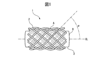
- FIG. 1 is a schematic diagram illustrating a configuration example of a braided piezoelectric element according to the embodiment.
- the braided piezoelectric element 1 includes a core portion 3 formed of a conductive fiber B and a sheath portion 2 formed of a braided piezoelectric fiber A so as to cover the core portion 3.
- the piezoelectric fiber A can contain polylactic acid as a main component.
- FIG. 2 is a schematic diagram illustrating a configuration example of a braided piezoelectric element according to an embodiment including a conductive layer.
- the braided piezoelectric element 1 covers the core 3 formed of the conductive fiber B, the sheath 2 formed of the braided piezoelectric fiber A so as to cover the core 3, and the sheath 2.
- the coverage of the sheath 2 by the conductive layer 4 is preferably 25% or more.
- the coverage is the ratio of the area of the conductive region contained in the conductive layer 4 and the surface area of the sheath 2 when the conductive layer 4 is projected onto the sheath 2, and its value is preferably 25% or more, It is more preferably 50% or more, and further preferably 75% or more. If the coverage of the conductive layer 4 is less than 25%, the noise signal suppressing effect may not be sufficiently exhibited.
- the sheath portion 2 When the conductive region is not exposed to the surface of the conductive layer 4, for example, when the sheath portion 2 is covered by using a fiber that encloses the conductive region as the conductive layer 4, go to the sheath portion 2 of the fiber.
- the ratio of the projected area to the surface area of the sheath 2 can be defined as the coverage.
- the conductive region is a portion responsible for conductivity contained in the conductive layer 4, and refers to a conductive fiber portion when the conductive layer 4 is composed of conductive fibers and insulating fibers, for example.
- a large number of piezoelectric fibers A densely surround the outer peripheral surface of at least one conductive fiber B.
- a stress due to the deformation is generated in each of the many piezoelectric fibers A, thereby generating an electric field in each of the many piezoelectric fibers A. (Piezoelectric effect)
- piezoelectric effect As a result, it is presumed that a voltage change in which electric fields of a large number of piezoelectric fibers A surrounding the conductive fiber B are superimposed is generated in the conductive fiber B.
- the electrical signal from the conductive fiber B increases as compared with the case where the braided sheath 2 of the piezoelectric fiber A is not used.
- the braided piezoelectric element 1 can extract a large electric signal even by a stress generated by a relatively small deformation.
- a plurality of conductive fibers B may be used.
- the piezoelectric fiber A preferably contains polylactic acid as a main component.
- “As a main component” means that the most component of the components of the piezoelectric fiber A is polylactic acid.
- the lactic acid unit in the polylactic acid is preferably 90 mol% or more, more preferably 95 mol% or more, and even more preferably 98 mol% or more.
- the winding angle ⁇ of the piezoelectric fiber A with respect to the conductive fiber B is preferably 15 ° or more and 75 ° or less. That is, the winding angle ⁇ of the piezoelectric fiber A is preferably 15 ° or more and 75 ° or less with respect to the direction of the central axis CL of the conductive fiber B (core portion 3). However, in the present embodiment, the central axis CL of the conductive fiber B overlaps with the central axis (hereinafter, also referred to as “braid axis”) of the braided cord (sheath portion 2) of the piezoelectric fiber A.
- the winding angle ⁇ of the piezoelectric fiber A is preferably 15 ° or more and 75 ° or less with respect to the direction of the braid axis of A.
- the angle ⁇ is more preferably 25 ° or more and 65 ° or less, further preferably 35 ° or more and 55 ° or less, and 40 ° or more and 50 ° or less. Particularly preferred. This is because when the angle ⁇ is out of this angle range, the electric field generated in the piezoelectric fiber A is remarkably lowered, and the electrical signal obtained from the conductive fiber B is thereby remarkably lowered.
- the angle ⁇ can also be referred to as an angle formed by the main direction of the piezoelectric fiber A forming the sheath portion 2 and the central axis CL of the conductive fiber B, and a part of the piezoelectric fiber A is slackened. Or may be fuzzy.
- the piezoelectric fiber A has polylactic acid as a main component and is uniaxially oriented in the fiber axis direction of the piezoelectric fiber A.
- polylactic acid generates an electric field when shear stress is generated in the orientation direction (in this case, the direction of the fiber axis of the piezoelectric fiber A), but tensile stress or compression is applied in the orientation direction. Less electric field is generated when stress occurs.
- the orientation direction of the piezoelectric fiber A (polylactic acid) is within a predetermined angular range with respect to the braid axis. It is speculated that it is good to be.
- the sheath 2 may be mixed with fibers other than the piezoelectric fiber A, and the core 3 may be conductive. Mixing or the like may be performed in combination with fibers other than the fiber B.
- the length of the braided piezoelectric element constituted by 2 and the conductive layer 4 covering the sheath 2 is not particularly limited.
- the braided piezoelectric element may be manufactured continuously in manufacturing, and then cut to a required length for use.
- the length of the braided piezoelectric element is 1 mm to 10 m, preferably 5 mm to 2 m, more preferably 1 cm to 1 m. If the length is too short, the convenience of the fiber shape will be lost, and if the length is too long, it will be necessary to consider the resistance value of the conductive fiber B.
- the conductive fiber B any known fiber may be used as long as it exhibits conductivity.
- the conductive fiber B for example, metal fiber, fiber made of a conductive polymer, carbon fiber, fiber made of a polymer in which a fibrous or granular conductive filler is dispersed, or conductive on the surface of a fibrous material.
- the fiber which provided the layer which has is mentioned.
- the method for providing a conductive layer on the surface of the fibrous material include a metal coat, a conductive polymer coat, and winding of conductive fibers.
- a metal coat is preferable from the viewpoint of conductivity, durability, flexibility and the like. Specific methods for coating the metal include vapor deposition, sputtering, electrolytic plating, and electroless plating, but plating is preferable from the viewpoint of productivity.
- Such a metal-plated fiber can be referred to as a metal-plated fiber.
- a known fiber can be used regardless of conductivity, for example, polyester fiber, nylon fiber, acrylic fiber, polyethylene fiber, polypropylene fiber, vinyl chloride fiber, aramid fiber,
- synthetic fibers such as polysulfone fibers, polyether fibers and polyurethane fibers
- natural fibers such as cotton, hemp and silk
- semi-synthetic fibers such as acetate
- regenerated fibers such as rayon and cupra
- the base fibers are not limited to these, and known fibers can be arbitrarily used, and these fibers may be used in combination.
- any metal may be used as long as the metal coated on the base fiber exhibits conductivity and exhibits the effects of the present invention.
- gold, silver, platinum, copper, nickel, tin, zinc, palladium, indium tin oxide, copper sulfide, and a mixture or alloy thereof can be used.
- the conductive fiber B is made of an organic fiber coated with a metal having bending resistance, the conductive fiber is hardly broken, and is excellent in durability and safety as a sensor using a piezoelectric element.
- the conductive fiber B may be a multifilament in which a plurality of filaments are bundled or may be a monofilament composed of a single filament.
- the conductive fiber B may be a single spun yarn, a yarn bundle form in which a plurality of spun yarns are bundled (including twisted yarn), or a long / short composite yarn in which a filament and a spun yarn are combined.
- a multifilament is preferred from the viewpoint of long stability of electrical characteristics.
- the single yarn diameter is 1 ⁇ m to 5000 ⁇ m, preferably 2 ⁇ m to 100 ⁇ m. More preferably, it is 3 ⁇ m to 50 ⁇ m.
- the number of filaments to yarns is preferably 1 to 100,000, more preferably 5 to 500, and still more preferably 10 to 100.
- the fineness and the number of the conductive fibers B are the fineness and the number of the core part 3 used when producing the braid, and a multifilament formed of a plurality of single yarns (monofilaments) is also a plurality of spun yarns. Both the bundled yarn bundle form (including twisted yarn) and the long and short composite yarn obtained by combining the filament and the spun yarn are counted as one conductive fiber B.
- the core portion 3 is the total amount including the fibers other than the conductive fibers.
- the cross-sectional shape of the conductive fiber B is preferably a circle or an ellipse from the viewpoint of the design and manufacture of the piezoelectric element, but is not limited thereto.
- the electric resistance is preferably low, and the volume resistivity is preferably 10 ⁇ 1 ⁇ ⁇ cm or less, more preferably 10 ⁇ 2 ⁇ ⁇ cm. cm or less, more preferably 10 ⁇ 3 ⁇ ⁇ cm or less.
- the resistivity of the conductive fiber B is not limited to this as long as sufficient strength can be obtained by detection of the electric signal.
- the conductive fiber B must be resistant to movement such as repeated bending and twisting from the use of the present invention.
- the index one having a greater nodule strength is preferred.
- the nodule strength can be measured by the method of JIS L1013: 2010 8.6.
- the degree of knot strength suitable for the present invention is preferably 0.5 cN / dtex or more, more preferably 1.0 cN / dtex or more, and further preferably 1.5 cN / dtex or more. 2.0 cN / dtex or more is most preferable.
- the bending rigidity is generally measured by a measuring device such as KES-FB2 pure bending tester manufactured by Kato Tech Co., Ltd.
- the degree of bending rigidity suitable for the present invention is preferably smaller than the carbon fiber “Tenax” (registered trademark) HTS40-3K manufactured by Toho Tenax Co., Ltd.
- the bending stiffness of the conductive fiber is preferably 0.05 ⁇ 10 ⁇ 4 N ⁇ m 2 / m or less, and preferably 0.02 ⁇ 10 ⁇ 4 N ⁇ m 2 / m or less. and still more preferably not more than 0.01 ⁇ 10 -4 N ⁇ m 2 / m.
- piezoelectric fiber As the piezoelectric polymer that is the material of the piezoelectric fiber A, a polymer exhibiting piezoelectricity such as polyvinylidene fluoride or polylactic acid can be used. However, in the present embodiment, the piezoelectric fiber A is used as a main component as described above. It is preferred to include polylactic acid. Polylactic acid, for example, is easily oriented by drawing after melt spinning and exhibits piezoelectricity, and is excellent in productivity in that it does not require an electric field alignment treatment required for polyvinylidene fluoride and the like. However, this is not intended to exclude the use of polyvinylidene fluoride or other piezoelectric materials in the practice of the present invention.
- polylactic acid depending on its crystal structure, poly-L-lactic acid obtained by polymerizing L-lactic acid and L-lactide, D-lactic acid, poly-D-lactic acid obtained by polymerizing D-lactide, and those There are stereocomplex polylactic acid having a hybrid structure, and any of them can be used as long as it exhibits piezoelectricity. From the viewpoint of high piezoelectricity, poly-L-lactic acid and poly-D-lactic acid are preferable. Since poly-L-lactic acid and poly-D-lactic acid are reversed in polarization with respect to the same stress, they can be used in combination according to the purpose.
- the optical purity of polylactic acid is preferably 99% or more, more preferably 99.3% or more, and further preferably 99.5% or more. If the optical purity is less than 99%, the piezoelectricity may be remarkably lowered, and it may be difficult to obtain a sufficient electrical signal due to the shape change of the piezoelectric fiber A.
- the piezoelectric fiber A preferably contains poly-L-lactic acid or poly-D-lactic acid as a main component, and the optical purity thereof is preferably 99% or more.
- Piezoelectric fiber A containing polylactic acid as a main component is drawn during production and is uniaxially oriented in the fiber axis direction. Furthermore, the piezoelectric fiber A is not only uniaxially oriented in the fiber axis direction but also preferably contains polylactic acid crystals, and more preferably contains uniaxially oriented polylactic acid crystals. This is because polylactic acid exhibits higher piezoelectricity due to its high crystallinity and uniaxial orientation.
- Crystallinity and uniaxial orientation are determined by homo PLA crystallinity X homo (%) and crystal orientation Ao (%).
- the homo PLA crystallinity X homo (%) and the crystal orientation degree Ao (%) preferably satisfy the following formula (1).
- the value on the left side of the formula (1) is more preferably 0.28 or more, and further preferably 0.3 or more. Here, each value is obtained according to the following.
- Homopolylactic acid crystallinity X homo is obtained from crystal structure analysis by wide angle X-ray diffraction analysis (WAXD).
- WAXD wide angle X-ray diffraction analysis
- an X-ray diffraction pattern of a sample is recorded on an imaging plate under the following conditions by a transmission method using an Ultrax 18 type X-ray diffractometer manufactured by Rigaku.
- X-ray source Cu-K ⁇ ray (confocal mirror) Output: 45kV x 60mA Slit: 1st: 1mm ⁇ , 2nd: 0.8mm ⁇ Camera length: 120mm Accumulation time: 10 minutes Sample: 35 mg of polylactic acid fibers are aligned to form a 3 cm fiber bundle.
- homopolylactic acid crystallinity X homo is determined according to the following formula (2).
- Homopolylactic acid crystallinity X homo (%) ⁇ I HMi / I total ⁇ 100 (2) Note that ⁇ I HMi is calculated by subtracting diffuse scattering due to background and amorphous in the total scattering intensity.
- polylactic acid is a polyester that is hydrolyzed relatively quickly, in the case where heat and humidity resistance is a problem, a known hydrolysis inhibitor such as an isocyanate compound, an oxazoline compound, an epoxy compound, or a carbodiimide compound is added. Also good. Further, if necessary, the physical properties may be improved by adding an antioxidant such as a phosphoric acid compound, a plasticizer, a photodegradation inhibitor, and the like.
- Polylactic acid may be used as an alloy with other polymers. However, if polylactic acid is used as the main piezoelectric polymer, it contains at least 50% by mass or more based on the total mass of the alloy. Preferably, it is 70 mass% or more, Most preferably, it is 90 mass% or more.
- polymers other than polylactic acid in the case of alloy examples include polybutylene terephthalate, polyethylene terephthalate, polyethylene naphthalate copolymer, polymethacrylate, and the like, but the invention is not limited thereto. Any polymer may be used as long as the desired piezoelectricity is exhibited.
- the piezoelectric fiber A may be a multifilament in which a plurality of filaments are bundled, or may be a monofilament composed of a single filament, or may be a single spun yarn or a bundle of a plurality of spun yarns. It may be in the form (including twisted yarn) or may be a long / short composite yarn in which a filament and a spun yarn are combined.
- the single yarn diameter is 1 ⁇ m to 5 mm, preferably 5 ⁇ m to 2 mm, more preferably 10 ⁇ m to 1 mm.
- the single yarn diameter is 0.1 ⁇ m to 5 mm, preferably 2 ⁇ m to 100 ⁇ m, more preferably 3 ⁇ m to 50 ⁇ m.
- the number of filaments or yarns of the multifilament, yarn bundle form, and long / short composite yarn is preferably 1 to 100,000, more preferably 50 to 50,000, and still more preferably 100 to 20,000.
- the fineness and the number of the piezoelectric fibers A are the fineness and the number per carrier when producing the braid, and the multifilament formed by a plurality of single yarns (monofilaments) is also one piezoelectric. It shall be counted as fiber A.
- the total amount including that is used.
- any known technique for forming a fiber from the polymer can be employed as long as the effects of the present invention are exhibited.
- a method of extruding a piezoelectric polymer to form a fiber a method of melt-spinning a piezoelectric polymer to make a fiber, a method of making a piezoelectric polymer fiber by dry or wet spinning, a method of making a piezoelectric polymer A technique of forming fibers by electrostatic spinning, a technique of cutting thinly after forming a film, and the like can be employed.
- a known method may be applied according to the piezoelectric polymer to be employed, and a melt spinning method that is industrially easy to produce is usually employed. Furthermore, after forming the fiber, the formed fiber is stretched. As a result, a piezoelectric fiber A that is uniaxially oriented and exhibits large piezoelectricity including crystals is formed.
- the piezoelectric fiber A can be subjected to treatments such as dyeing, twisting, combining, heat treatment, etc., before making the braided one produced as described above.
- the piezoelectric fiber A may be broken when the braid is formed, the piezoelectric fiber A may be cut off or fluff may come out, so that the strength and wear resistance are preferably high. It is preferably 5 cN / dtex or more, more preferably 2.0 cN / dtex or more, further preferably 2.5 cN / dtex or more, and most preferably 3.0 cN / dtex or more.
- Abrasion resistance can be evaluated by JIS L1095 9.10.2 B method, etc., and the number of friction is preferably 100 times or more, more preferably 1000 times or more, and further preferably 5000 times or more. Most preferably, it is 10,000 times or more.
- the method for improving the wear resistance is not particularly limited, and any known method can be used.
- the crystallinity is improved, fine particles are added, or the surface is processed. Can do.
- a lubricant can be applied to the fibers to reduce friction.
- the shrinkage rate of the piezoelectric fiber is small from the shrinkage rate of the conductive fiber described above. If the difference in shrinkage rate is large, the braid may bend due to heat treatment during post-fabrication after fabric production or after fabric production or during actual use, or due to changes over time, the flatness of the fabric may deteriorate, or the piezoelectric signal will become weak. May end up.
- the shrinkage rate is quantified by the boiling water shrinkage rate described later, it is preferable that the boiling water shrinkage rate S (p) of the piezoelectric fiber and the boiling water shrinkage rate S (c) of the conductive fiber satisfy the following formula (4). .
- the left side of the above formula (4) is more preferably 5 or less, and even more preferably 3 or less.
- the contraction rate of the piezoelectric fiber is small in difference from the contraction rate of fibers other than the conductive fibers, for example, insulating fibers. If the difference in shrinkage rate is large, the braid may bend due to heat treatment during post-fabrication after fabric production or after fabric production or during actual use, or due to changes over time, the flatness of the fabric may deteriorate, or the piezoelectric signal will become weak. May end up.
- the shrinkage rate is quantified by the boiling water shrinkage rate, it is preferable that the boiling water shrinkage rate S (p) of the piezoelectric fiber and the boiling water shrinkage rate S (i) of the insulating fiber satisfy the following formula (5).
- the left side of the above formula (5) is more preferably 5 or less, and even more preferably 3 or less.
- the shrinkage rate of the piezoelectric fiber is small.
- the shrinkage rate of the piezoelectric fiber is preferably 15% or less, more preferably 10% or less, further preferably 5% or less, and most preferably 3% or less. is there.
- any known method can be applied.
- the shrinkage rate can be reduced by relaxing the orientation of the amorphous part or increasing the crystallinity by heat treatment, and the heat treatment is performed.
- the timing is not particularly limited, and examples thereof include after stretching, after twisting, after braiding, and after forming into a fabric.
- boiling water shrinkage shall be measured with the following method.
- a casserole of 20 times was made with a measuring machine having a frame circumference of 1.125 m, a load of 0.022 cN / dtex was applied, it was hung on a scale plate, and the initial casket length L0 was measured. After that, this casserole was treated in a boiling water bath at 100 ° C. for 30 minutes, allowed to cool, and again subjected to the above load and hung on the scale plate to measure the length L after shrinkage.
- the boiling water shrinkage is calculated by the following equation (6).
- Boiling water shrinkage (L0 ⁇ L) / L0 ⁇ 100 (%) (6)
- the surface of the conductive fiber B, that is, the core portion 3 is covered with the piezoelectric fiber A, that is, the braided sheath portion 2.
- the thickness of the sheath 2 covering the conductive fiber B is preferably 1 ⁇ m to 10 mm, more preferably 5 ⁇ m to 5 mm, still more preferably 10 ⁇ m to 3 mm, and most preferably 20 ⁇ m to 1 mm. preferable. If it is too thin, there may be a problem in terms of strength. If it is too thick, the braided piezoelectric element 1 may become hard and difficult to deform.
- the sheath part 2 said here refers to the layer adjacent to the core part 3.
- the total fineness of the piezoelectric fibers A in the sheath 2 is preferably not less than 1/2 times and not more than 20 times the total fineness of the conductive fibers B in the core 3. 15 times or less, more preferably 2 times or more and 10 times or less. If the total fineness of the piezoelectric fiber A is too small relative to the total fineness of the conductive fiber B, the piezoelectric fiber A surrounding the conductive fiber B is too small and the conductive fiber B cannot output a sufficient electrical signal, Furthermore, there exists a possibility that the conductive fiber B may contact the other conductive fiber which adjoins.
- the total fineness of the piezoelectric fiber A is too large relative to the total fineness of the conductive fiber B, there are too many piezoelectric fibers A surrounding the conductive fiber B, and the braided piezoelectric element 1 becomes hard and difficult to deform. That is, in any case, the braided piezoelectric element 1 does not sufficiently function as a sensor.
- the total fineness referred to here is the sum of the finenesses of all the piezoelectric fibers A constituting the sheath portion 2. For example, in the case of a general 8-strand braid, it is the sum of the finenesses of 8 fibers.
- the fineness per piezoelectric fiber A of the sheath 2 is preferably 1/20 or more and 2 or less the total fineness of the conductive fiber B. It is more preferably 15 times or more and 1.5 times or less, and further preferably 1/10 time or more and 1 time or less. If the fineness per piezoelectric fiber A is too small with respect to the total fineness of the conductive fiber B, the piezoelectric fiber A is too small and the conductive fiber B cannot output a sufficient electric signal. A may be cut off.
- the piezoelectric fiber A If the fineness per piezoelectric fiber A is too large relative to the total fineness of the conductive fiber B, the piezoelectric fiber A is too thick and the braided piezoelectric element 1 becomes hard and difficult to deform. That is, in any case, the braided piezoelectric element 1 does not sufficiently function as a sensor.
- the fineness ratio is not limited to the above. This is because, in the present invention, the ratio is important in terms of contact area and coverage, that is, area and volume. For example, when the specific gravity of each fiber exceeds 2, it is preferable that the ratio of the average cross-sectional area of the fiber is the ratio of the fineness.
- an anchor layer or an adhesive layer is provided between the conductive fiber B and the piezoelectric fiber A in order to improve the adhesiveness. May be.
- the coating method a method is used in which the conductive fiber B is used as a core thread and the piezoelectric fiber A is wound around the braid in the form of a braid.
- the shape of the braid of the piezoelectric fiber A is not particularly limited as long as an electric signal can be output with respect to the stress generated by the applied load.
- a braided string is preferred.
- the shape of the conductive fiber B and the piezoelectric fiber A is not particularly limited, but is preferably as close to a concentric circle as possible.
- the piezoelectric fiber A only needs to be covered so that at least a part of the surface (fiber peripheral surface) of the multifilament of the conductive fiber B is in contact.
- the piezoelectric fibers A may or may not be coated on all filament surfaces (fiber peripheral surfaces) constituting the multifilament. What is necessary is just to set suitably the covering state of the piezoelectric fiber A to each internal filament which comprises the multifilament of the conductive fiber B, considering the performance as a piezoelectric element, the handleability, etc.
- the braided piezoelectric element 1 of the present invention does not require an electrode to be present on the surface thereof, there is no need to further cover the braided piezoelectric element 1 itself, and there is an advantage that malfunction is unlikely.
- a film, a fabric, and a fiber may be wound, or they may be combined.
- any coating containing a substance exhibiting conductivity may be used, and any known one may be used.
- a metal, a conductive polymer, and a polymer in which a conductive filler is dispersed can be given.
- the conductive layer 4 is formed by winding a film
- a film obtained by forming a conductive polymer and a polymer dispersed with a conductive filler is used, and a conductive layer is provided on the surface.
- a film may be used.
- the conductive layer 4 is formed by winding a fabric
- a fabric having a conductive fiber 6 described later as a constituent component is used.
- the fiber used is the conductive fiber 6, and the conductive fiber 6 may be the same type as the conductive fiber B or a different type of conductive fiber.
- the conductive fiber 6 include metal fibers, fibers made of a conductive polymer, carbon fibers, fibers made of a polymer in which a fibrous or granular conductive filler is dispersed, or conductive on the surface of the fibrous material. The fiber which provided the layer which has is mentioned.
- Examples of the method for providing a conductive layer on the surface of the fibrous material include a metal coat, a conductive polymer coat, and winding of conductive fibers.
- a metal coat is preferable from the viewpoint of conductivity, durability, flexibility and the like.
- Specific methods for coating the metal include vapor deposition, sputtering, electrolytic plating, electroless plating, and the like, but plating is preferable from the viewpoint of productivity.
- Such a metal-plated fiber can be referred to as a metal-plated fiber.
- a known fiber can be used regardless of conductivity, for example, polyester fiber, nylon fiber, acrylic fiber, polyethylene fiber, polypropylene fiber, vinyl chloride fiber, aramid fiber,
- synthetic fibers such as polysulfone fibers, polyether fibers and polyurethane fibers
- natural fibers such as cotton, hemp and silk
- semi-synthetic fibers such as acetate
- regenerated fibers such as rayon and cupra
- the base fibers are not limited to these, and known fibers can be arbitrarily used, and these fibers may be used in combination.
- any metal may be used as long as the metal coated on the base fiber exhibits conductivity and exhibits the effects of the present invention.
- gold, silver, platinum, copper, nickel, tin, zinc, palladium, indium tin oxide, copper sulfide, and a mixture or alloy thereof can be used.
- the conductive fiber 6 is made of an organic fiber coated with a metal having bending resistance, the conductive fiber is hardly broken and excellent in durability and safety as a sensor using a piezoelectric element.
- the conductive fiber 6 may be a multifilament in which a plurality of filaments are bundled, or may be a monofilament composed of a single filament, or may be a single spun yarn or a bundle of a plurality of spun yarns. It may be in the form (including twisted yarn) or may be a long / short composite yarn in which a filament and a spun yarn are combined.
- a multifilament is preferred from the viewpoint of long stability of electrical characteristics.
- the single yarn diameter is 1 ⁇ m to 5000 ⁇ m, preferably 2 ⁇ m to 100 ⁇ m. More preferably, it is 3 ⁇ m to 50 ⁇ m.
- the number of filaments or yarns is preferably 1 to 100,000, more preferably 5 to 500, and still more preferably 10 to 100.
- the cross-sectional shape of the conductive fiber 6 is preferably a circle or an ellipse from the viewpoint of design and manufacture of the piezoelectric element, but is not limited thereto.
- the electrical resistance is preferably low, and the volume resistivity is preferably 10 ⁇ 1 ⁇ ⁇ cm or less, more preferably 10 ⁇ 2 ⁇ ⁇ cm or less, and still more preferably. Is 10 ⁇ 3 ⁇ ⁇ cm or less.
- the resistivity is not limited as long as a noise signal suppressing effect can be obtained.
- the conductive fiber 6 must be resistant to movement such as repeated bending and twisting from the application of the present invention.
- the index one having a greater nodule strength is preferred.
- the nodule strength can be measured by the method of JIS L1013 8.6.
- the degree of knot strength suitable for the present invention is preferably 0.5 cN / dtex or more, more preferably 1.0 cN / dtex or more, and further preferably 1.5 cN / dtex or more. 2.0 cN / dtex or more is most preferable.
- the bending rigidity is generally measured by a measuring device such as KES-FB2 pure bending tester manufactured by Kato Tech Co., Ltd.
- the degree of bending rigidity suitable for the present invention is preferably smaller than the carbon fiber “Tenax” (registered trademark) HTS40-3K manufactured by Toho Tenax Co., Ltd.
- the flexural rigidity of the conductive fiber is preferably 0.05 ⁇ 10 ⁇ 4 N ⁇ m 2 / m or less, and preferably 0.02 ⁇ 10 ⁇ 4 N ⁇ m 2 / m or less. More preferably, it is more preferably 0.01 ⁇ 10 ⁇ 4 N ⁇ m 2 / m or less.
- the braided piezoelectric element 1 of the present invention further includes a metal terminal connected and fixed to the core portion in any of the following modes A and B.
- a part of the metal terminal grips a part of the fiber constituting the terminal part of the braided piezoelectric element having a length of 0.5 mm or more, and the braid is located within 1 mm from the gripped part or the gripped part.
- a state in which the core portion of the piezoelectric element and the metal terminal are fixedly connected directly or indirectly via a conductive material.
- a part of the metal terminal is fork-shaped or needle-shaped, and the fork-shaped portion or needle-shaped portion is in contact with the sheath portion of the braided piezoelectric element while directly or electrically conducting material with the conductive fiber in the core portion.
- the braided piezoelectric element is fixed to the metal terminal by another part of the metal terminal or a part fixed to the metal terminal at a location within 10 mm from the connection location.
- the braided piezoelectric element 1 of the present invention further includes a signal metal terminal connected and fixed to the core portion and a shield metal terminal connected and fixed to the conductive layer 4 provided around the sheath portion.
- the signal metal terminal and the shield metal terminal are fixed to each other via an insulator, and since these two metal terminals can be handled as an integrated connector part, connection to a signal processing circuit is possible. It is simple and reliable, and can stably reduce noise.
- the shielding metal terminal covers and holds the signal metal terminal via an insulator from the viewpoint of reducing noise entering at the terminal portion.
- Covering here means that the metal terminal for shielding is placed close to the signal metal terminal, and in that state it is projected on the front view, rear view, left side view, right side view, plan view and bottom view.
- the ratio of the area where the shield metal terminal regions overlap is 50% or more of the total area of the signal metal terminal regions in each figure.
- the signal metal terminal of the braided piezoelectric element 1 of the present invention is preferably connected and fixed to the core portion in one of the following modes A and B.
- a part of the signal metal terminal is fork-like or needle-like, and the fork-like part or needle-like part is in direct contact with the conductive fiber of the core part or while being in contact with the sheath part of the braided piezoelectric element.
- the braided piezoelectric element is connected to the signal metal by another part of the signal metal terminal or a part fixed to the signal metal terminal at a location within 10 mm from the connection location, indirectly connected through the material. A state fixed to the terminal made of.
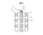
- FIG. 3 is a schematic diagram showing a configuration example of the connection mode A according to the embodiment.
- the piezoelectric fiber and the conductive fiber constituting the end of the braided piezoelectric element 1 are held by a holding portion 21 that is a part of the metal terminal 20.
- the gripped state refers to a state in which the braided piezoelectric element 1 is sandwiched or wound by the grip portion 21 of the metal terminal 20 and fixed to each other.
- a structure in which the metal terminal 20 formed into a nail shape is plastically deformed by a tool to be held is preferably employed.
- the metal terminal has a shape that can be connected to another terminal on the right side of FIG.
- the gripping portion 21 of the metal terminal 20 has a length of 0.5 mm or more. If the length is shorter than this, the braided piezoelectric element 1 and the metal terminal 20 are not easily fixed, and various forces are applied to the element for wearable device applications. When added, the braided piezoelectric element 1 and the metal terminal 20 may be separated or the electrical connection may become unstable.
- the length of the grip portion 21 is preferably 0.7 mm or more, and more preferably 1.0 mm or more.
- the length of the gripping portion 21 is the length that the braided piezoelectric element 1 is gripped by the metal terminal 20 and is the length measured in the length direction of the braided piezoelectric element 1. However, when the braided piezoelectric element 1 is gripped at a plurality of positions as shown in FIG. 3 (mode A), it is the total length of the gripped portions.
- the core portion 3 of the braided piezoelectric element 1 and the metal terminal 20 are connected directly or indirectly via a conductive material at the grip portion 21 of the metal terminal 20 or within a place within 1 mm from the grip portion 21. .
- the sheath portion 2 of the braided piezoelectric element 1 is not unraveled at the fixing portion with the metal terminal 20, and therefore, Even in the gripping portion 21 of the metal terminal 20, the sheath 2 is not completely removed, and the braided cord can be removed by partially removing the sheath 2 by melting or applying a conductive material such as solder or conductive paste.
- the core part of the piezoelectric element 1 and the metal terminal 20 can be electrically connected.
- a connector housing 22 as an exterior of the metal terminal 20, and the metal terminal 20 holding the braided piezoelectric element 1 is inserted from the opening on the left side of the connector housing 22.
- another terminal can be connected to the metal terminal 20 inside the connector housing from the opening 23 on the right side of the connector housing 22.
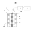
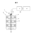
- FIG. 4 is a schematic diagram showing a configuration example of the connection mode A according to the embodiment including the conductive layer 4.
- the piezoelectric fiber and the conductive fiber constituting the end of the braided piezoelectric element 1 are held by a holding portion 31 which is a part of the signal metal terminal 30.
- the gripped state refers to a state in which the braided piezoelectric element 1 is sandwiched or wound by the grip portion 31 of the signal metal terminal 30 and fixed to each other.
- the structure is such that the signal metal terminal 30 formed into a nail shape is plastically deformed by a tool to be in the above-described gripped state, or is engaged by an engagement portion provided on the signal metal terminal 30 or the insulating portion.
- the signal metal terminal 30 has a shape that can be connected to another terminal on the right side of FIG.
- the signal metal terminal 30 is fixed to the shield metal terminal 34 via the insulator 32, and the shield metal terminal 34 is disposed so as to cover the signal metal terminal 30.
- the shield metal terminal 34 has a grip portion 31, and the conductive layer 4 is gripped by the grip portion 31 to be electrically connected and fixed to the conductive layer 4. In the example of FIG.
- the piezoelectric fiber and the conductive fiber constituting the end of the braided piezoelectric element are held by the holding portion of the signal metal terminal, but the piezoelectric fiber constituting the end of the braided piezoelectric element is It is not always necessary to be held by the holding portion of the signal metal terminal.
- the connector parts that can perform such connection the coaxial connectors disclosed in Japanese Patent Laid-Open Nos. 4-282580, 2002-324636, 2012-79562, and the like can be suitably used.
- the gripping portion 31 of the signal metal terminal 30 is preferably 0.5 mm or more in length. If the length is shorter than this, the braided piezoelectric element 1 and the signal metal terminal 30 are not easily fixed, and the wearable device is used. When various forces are applied to the element, the braided piezoelectric element 1 and the signal metal terminal 30 may be separated or the electrical connection may become unstable.
- the length of the grip portion 31 is more preferably 0.7 mm or more, and further preferably 1.0 mm or more.
- the length of the gripping portion 31 is the length of the braided piezoelectric element 1 held by the signal metal terminal 30 and is the length measured in the length direction of the braided piezoelectric element 1. When the metal terminal 30 is holding the braided piezoelectric element 1 at a plurality of places as shown in FIG. 4, the total length of the holding portions is obtained.
- the core portion 3 of the braided piezoelectric element 1 and the signal metal terminal 30 are directly or indirectly through a conductive material. It is connected.
- the sheath portion 2 of the braided piezoelectric element 1 is not unraveled at the fixing portion with the signal metal terminal 30 as described later in the present invention. Even in the grip portion 31 of the terminal 30, the sheath 2 is not completely removed, and the braided piezoelectric material is obtained by partial removal by melting the sheath 2 or application of a conductive material such as solder or conductive paste.
- the core portion 3 of the element 1 and the signal metal terminal 30 can be electrically connected.
- the insulator 32 that fixes the signal metal terminal 30 sufficiently holds the sheath portion 2 even when the sheath portion 2 is released by the cutting operation at the end of the braided piezoelectric element 1 or the removal operation of the sheath portion 2.
- this is not the case when it can be considered that the sheath 2 is not substantially unraveled, that is, when it does not become a harmful noise source.
- FIG. 5 (mode B fork shape) is a schematic diagram showing a configuration example of the connection mode by the metal terminal 20 including the fork-like portion 25 of the mode B according to the embodiment.
- FIG. 6 (mode B needle shape) is a schematic diagram showing a configuration example of the connection mode by the metal terminal 20 including the needle-like portion 26 of the mode B according to the embodiment.
- the fork-like portion 25 or the needle-like portion 26 which is a part of the metal terminal 20 is braided.
- the metal terminal 20 While being in contact with the sheath portion 2 of the piezoelectric element 1, it is directly connected to the conductive fiber of the core portion 3 or indirectly through a conductive material.
- the metal terminal 20 has a shape that can be connected to another terminal on the right side of each drawing.
- the braided piezoelectric element 1 is fixed only by the fork-like portion 25 or the needle-like portion 26 of the metal terminal 20, so that the component fixed to another part of the metal terminal 20 or the metal terminal 20 is used. Also, the braided piezoelectric element 1 is fixed to the metal terminal 20, and this fixing part is required within 10 mm from the connection point of the metal terminal 20 and the conductive fiber of the core part 3. When there is a fixed part only at a part exceeding 10 mm from the connection part, the entire braided piezoelectric element 1 which is not fixed and the sheath part 2 which is unwound by the metal terminal 20 move unstablely due to impact on the sensor, etc. Cause.
- the braided piezoelectric element 1 is held by a part of the metal terminal 20 as in the mode A.
- the braided piezoelectric element 1 is sandwiched and held by a component such as a resin housing fixed to the metal terminal 20, or the metal terminal 20 or a component fixed to the metal terminal 20 by an adhesive. More preferably, it is fixed.
- a connector housing 22 is provided as an exterior of the metal terminal 20, and the braided piezoelectric element 1 is formed at the left side of the connector housing 22 in the figure. It is set as the fixing
- the connector housing 22 is divided into two parts, an upper part and a lower part, as shown in each cross-sectional view (B) of FIG. 5 (mode B fork shape) and FIG. 6 (mode B needle shape). 20 is fixed in advance.
- the braided piezoelectric element 1 When connecting and fixing the braided piezoelectric element 1 to the metal terminal 20, the braided piezoelectric element 1 is sandwiched between the metal terminal 20 fixed to the upper part of the connector housing 22 and the lower part of the connector housing 22, and a force is applied from above and below.
- the metal terminal 20 is inserted into the braided piezoelectric element 1 and the upper and lower connector housings 22 are fixed in contact with each other. Therefore, the fork-like portion 25 or the needle-like portion 26 of the metal terminal 20 has a thinness or thinness necessary for being inserted between the fibers of the piezoelectric fiber of the sheath portion 2, or It is preferable that the sharpness necessary for partially cutting the piezoelectric fiber is provided.
- One metal terminal 20 may have a plurality of fork-like portions 25 or a plurality of needle-like portions 26, or may be provided with the fork-like portions 25 and the needle-like portions 26 at the same time.
- the fork-like portion hardly comes into contact with the core portion 3 if the thickness of the sheath portion 2 is too thick or the total fineness of the core portion is too low.
- the thickness of is preferably 1 mm or less, more preferably 0.5 mm or less, and the total fineness of the core 3 is preferably 50 dTex or more, more preferably 100 dTex or more.
- FIG. 5 (mode B fork shape) and FIG. 6 (mode B needle shape) another terminal can be connected to the metal terminal 20 inside the connector housing 22 from the opening 23 on the right side of the connector housing 22. Yes.
- FIG. 7 is a schematic view showing a configuration example of a connection mode by the signal metal terminal 30 including the fork-like portion 35 of the mode B according to the embodiment including the conductive layer 4.
- FIG. 8 is a schematic diagram showing a configuration example of a connection mode by the signal metal terminal 30 including the needle-shaped portion 36 of the mode B according to the embodiment including the conductive layer 4. 7 and 8, the fork-like portion 35 or the needle-like portion 36 which is a part of the signal metal terminal 30 is in contact with the sheath portion 2 of the braided piezoelectric element 1 as shown in the respective sectional views. However, it is connected to the conductive fiber of the core part 3 directly or indirectly through a conductive material.
- the signal metal terminal 30 has a shape that can be connected to another terminal on the right side of each figure.
- the signal metal terminal 30 is fixed to the shield metal terminal 34 via the insulator 32, and the shield metal terminal 34 is disposed so as to cover the signal metal terminal 30.
- the shield metal terminal 34 has a grip portion 31, and the conductive layer 4 is gripped by the grip portion 31 to be electrically connected and fixed to the conductive layer 4.
- a stack type cable connector disclosed in Japanese Patent Application Laid-Open No. 2006-277960 can be suitably used as a connector component that can perform such connection.
- the braided piezoelectric element 1 is preferably fixed to the signal metal terminal 30 by a component fixed to the signal metal terminal 30.
- the sheath part 2 unraveled by the braided piezoelectric element 1 that is not fixed and the signal metal terminal 30 is unstable due to an impact on the sensor or the like. It can cause movement and noise.
- the braid is partially formed by a part of the signal metal terminal 30 as in the mode A.
- the piezoelectric element 1 can be gripped, but the braided piezoelectric element 1 is sandwiched and held by parts such as a resin housing fixed to the signal metal terminal 30, or the signal metal terminal 30 or It is more preferable to fix to the component fixed to the signal metal terminal 30.
- an insulator 32 is provided as an exterior of the signal metal terminal 30, and the braided piezoelectric element 1 is sandwiched between the left portions of the insulator 32 in the drawing. It is set as the fixing
- the insulator 32 is divided into two parts, an upper part and a lower part, as shown in each cross-sectional view (B) of FIGS. 7 and 8, and the upper part of the insulator 32 may be fixed to the signal metal terminal 30 in advance. Good.
- the braided piezoelectric element 1 When the braided piezoelectric element 1 is connected and fixed to the signal metal terminal 30, the braided piezoelectric element 1 is sandwiched between the signal metal terminal 30 fixed to the upper part of the insulator 32 and the lower part of the insulator 32, and further It is preferable that the signal metal terminal 30 is inserted into the braided piezoelectric element 1 by applying force from above and below, and the upper and lower insulators 32 are fixed in contact with each other. Therefore, the fork-like portion 35 or the needle-like portion 36 of the signal metal terminal 30 has a thinness or thinness required for being inserted between the fibers of the piezoelectric fiber of the sheath portion 2, or the sheath portion.
- One signal metal terminal 30 may have a plurality of fork-like portions 35 or a plurality of needle-like portions 36, or may be provided with the fork-like portions 35 and the needle-like portions 36 at the same time.
- the signal metal terminal 30 having the fork-like portion 35 it is difficult for the fork-like portion 35 to come into contact with the core portion 3 if the thickness of the sheath portion 2 is too thick or the total fineness of the core portion 3 is too low.
- the thickness of the sheath part 2 is preferably 1 mm or less, more preferably 0.5 mm or less, and the total fineness of the core part 3 is preferably 50 dTex or more, more preferably 100 dTex or more.
- the braided piezoelectric element of the present invention has a piezoelectric fiber that is separated from the core portion by unraveling the tissue of the sheath portion at the end of the portion fixed by the signal metal terminal or a part fixed to the metal terminal. , Having a portion that is less than 20% of the total piezoelectric fiber of the sheath. If it exceeds 20%, the piezoelectric fiber away from the core portion moves in an unstable manner due to an impact on the sensor or the like, so that a piezoelectric signal is randomly generated and causes noise.
- the portion where the braided piezoelectric element is fixed by a metal terminal or a part fixed to the metal terminal is a portion held by the metal terminal in the mode A, or a fork-shaped portion of the metal terminal and the needle in the mode B
- a portion in which the braided piezoelectric element is in contact with the sheath of the braided piezoelectric element, a portion in which the braided piezoelectric element is sandwiched and held by parts such as a resin housing fixed to the metal terminal in the modes A and B, an adhesive Indicates a portion where the braided piezoelectric element is fixed to a metal terminal or a component fixed to the metal terminal.
- the end refers to a region within 1 mm from the boundary between the fixed part and the non-fixed part.
- the piezoelectric fiber of the sheath part reaches from the core part surface to a place where the distance is 1.5 times or more the average thickness of the sheath part of the braided piezoelectric element. It is determined for each piezoelectric fiber (that is, fiber supplied from one carrier when creating a braid).
- the piezoelectric fiber of the sheath part is a multifilament, 50% or more of the filaments constituting one piezoelectric fiber is a distance of 1.5 times or more the average thickness of the sheath part of the braided piezoelectric element from the core surface.
- one piezoelectric fiber is separated from the core portion by unraveling the tissue of the sheath portion.
- the determination may be observed from the side surface of the braided piezoelectric element, or a cross section may be observed.
- observing the cross section it is cut and observed after being fixed with an epoxy resin or the like so that the sheath portion is not unraveled excessively at the time of cutting.
- the metal terminals for signals of the element of the present invention are braided as shown in FIGS. 3 and 4 (mode A), FIGS. 5 and 7 (mode B forks) and FIGS. 6 and 8 (mode B needles). It can be fixed to the end of the piezoelectric element 1 or can be fixed in the middle of the braided piezoelectric element 1.
- the element of the present invention fixes the metal terminal for signal without removing the fiber of the sheath portion of the braid that is an insulating coating, and also the core and signal It has a seemingly contradictory structure that ensures electrical connection of metal terminals.
- the following two examples are given as structures for achieving this.
- a structure in which some or all of the piezoelectric fibers in the sheath within 5 mm from the connecting portion between the core and the signal metal terminal lose the fiber shape and are fused is preferably employed. That is, the piezoelectric fiber of the sheath part that prevents the electrical connection between the metal terminal and the core part is caused to flow by melting of the piezoelectric fiber constituting the sheath part after fixing the metal terminal, and the metal terminal and the core part After securing the electrical connection, the piezoelectric fiber can be solidified and fixed again by cooling or the like. The solid solidified after the piezoelectric fiber is melted has an advantage that the braided piezoelectric element and the metal terminal can be fixed like an adhesive.
- the solid that has been solidified after melting loses piezoelectricity, and therefore does not become a noise source.
- the solidified piezoelectric fibers can be melted by heat treatment at a temperature of 160 ° C. or higher.
- unnecessary decomposition of polylactic acid and unnecessary melting of the sheath and deformation of other members are possible. In order to prevent this, it is preferable to carry out at 220 ° C. or lower.
- the melting of the piezoelectric fiber can also be performed when the metal terminal is fixed, and it is preferable to increase the gripping pressure of the metal terminal while confirming whether the electrical connection is secured, and unnecessary deformation of the sheath In order to prevent this, it is preferable to heat and melt the metal terminal to transmit heat to the sheath. From the viewpoint of process safety and the ability to process a plurality of elements at the same time, it is also preferable to carry out after attaching the metal terminal.
- the surface of the sheath includes a conductive material made of solder or conductive paste, electrically connected to the core, and the conductive material and signal metal provided on the surface of the sheath
- the conductive material has a function of interposing between the core portion and the metal terminal and electrically conducting, and changes from liquid (including slurry) to solid by temperature change, solvent removal, and chemical reaction. Any material can be used, and a conductive paste containing a conductive filler such as solder, metal or carbon is preferably used. In particular, solder and silver paste are preferably used from the viewpoint of handleability and conductivity.
- the braided piezoelectric element of the present invention is an aggregate of fibers with an insulation coating
- the conductive surface is infiltrated by adhering the above-mentioned conductive material from the surface, and the conductive surface electrically connected to the core portion is the sheath surface.
- adjust the fluidity before solidifying the conductive material to make it easier to penetrate the core, or before solidifying the conductive material It is preferable to apply a physical stimulus to the braided piezoelectric element to widen the gap between the fibers in the sheath, or to attach a conductive material to the cut surface at the end of the braided piezoelectric element.
- the braided piezoelectric element of the present invention is a cloth within a range of 10 mm or less from the portion where the signal metal terminal or the shield metal terminal is fixed to the braided piezoelectric element. It is preferable to be fixed to the substrate. When there is no place fixed to the cloth-like base material within 10 mm, the braided piezoelectric element that is not fixed moves unstable due to an impact on the cloth-like base material and the metal terminal, and causes noise.
- the fixing to the cloth-like substrate may be performed by post-processing such as adhesion and sewing, or may be fixed by weaving or knitting as a yarn constituting the fabric structure.
- the surface of at least one conductive fiber B is covered with the braided piezoelectric fiber A.
- the manufacturing method include the following methods. In other words, the conductive fiber B and the piezoelectric fiber A are produced in separate steps, and the conductive fiber B is wrapped around the conductive fiber B in a braid shape and covered. In this case, it is preferable to coat so as to be as concentric as possible.
- the melt spinning temperature is preferably 150 ° C. to 250 ° C.
- the stretching temperature is preferably 40 ° C. to 150 ° C.
- the draw ratio is preferably 1.1 to 5.0 times
- the crystallization temperature is preferably 80 ° C to 170 ° C.
- a multifilament in which a plurality of filaments are bundled may be used, a monofilament may be used, or a single spun yarn or a plurality of spun yarns may be used. Bundles of yarns (including twisted yarns) may be used, and long and short composite yarns combining filaments and spun yarns may be used.
- a multifilament in which a plurality of filaments are bundled may be used, or a monofilament may be used.
- a single spun yarn, a yarn bundle form (including twisted yarn) in which a plurality of spun yarns are bundled, or a long / short composite yarn in which a filament and a spun yarn are combined may be used.
- the conductive fiber B can be used as a core yarn, and the piezoelectric fiber A can be formed in a braid shape around the conductive fiber B to form a round braid. . More specifically, an 8-strand braid having 16 cores and a 16-strand braid are included. However, for example, the piezoelectric fiber A may be shaped like a braided tube, and the conductive fiber B may be used as a core and inserted into the braided tube.
- the conductive layer 4 is manufactured by coating or fiber winding, but fiber winding is preferable from the viewpoint of ease of manufacture.
- a method for winding the fiber a cover ring, a knitted fabric, and a braid are conceivable, and any method may be used.
- the braided piezoelectric element 1 in which the surface of the conductive fiber B is covered with the braided piezoelectric fiber A and the conductive layer 4 is provided around the surface as necessary can be obtained.
- the braided piezoelectric element 1 of the present invention does not require the formation of an electrode for detecting an electric signal on the surface, it can be manufactured relatively easily.
- a protective layer may be provided on the outermost surface of the braided piezoelectric element 1 of the present invention.
- This protective layer is preferably insulative, and more preferably made of a polymer from the viewpoint of flexibility.
- the entire protective layer is deformed or rubbed on the protective layer, but these external forces reach the piezoelectric fiber A, There is no particular limitation as long as it can induce polarization.
- the protective layer is not limited to those formed by coating with a polymer or the like, and may be a film, fabric, fiber or the like, or a combination thereof.
- the shape of the piezoelectric element can also be formed by this protective layer.
- the electromagnetic wave shielding layer is not particularly limited, but may be coated with a conductive substance, or may be wound with a conductive film, fabric, fiber, or the like.
- the volume resistivity of the electromagnetic wave shielding layer is preferably 10 ⁇ 1 ⁇ ⁇ cm or less, more preferably 10 ⁇ 2 ⁇ ⁇ cm or less, still more preferably 10 ⁇ 3 ⁇ ⁇ cm or less.
- the resistivity is not limited as long as the effect of the electromagnetic wave shielding layer can be obtained.
- This electromagnetic wave shielding layer may be provided on the surface of the piezoelectric fiber A of the sheath, or may be provided outside the protective layer described above.
- a plurality of layers of electromagnetic shielding layers and protective layers may be laminated, and the order thereof is appropriately determined according to the purpose.
- a plurality of layers made of piezoelectric fibers can be provided, or a plurality of layers made of conductive fibers for taking out signals can be provided.
- the order and the number of layers of these protective layers, electromagnetic wave shielding layers, layers made of piezoelectric fibers, and layers made of conductive fibers are appropriately determined according to the purpose.
- the method of winding the method of forming a braid structure in the outer layer of the sheath part 2, or covering it is mentioned.
- the braided piezoelectric element 1 of the present invention is, for example, a stress generated when a load is applied to the braided piezoelectric element 1 by rubbing the surface of the braided piezoelectric element 1, that is, a stress applied to the braided piezoelectric element 1. It can be used as a sensor for detecting the size and / or application position.
- the braided piezoelectric element 1 of the present invention can take out an electrical signal as long as shear stress is applied to the piezoelectric fiber A by pressing force other than rubbing or bending deformation.
- the “applied stress” to the braided piezoelectric element 1 includes the frictional force between the surface of the piezoelectric element, that is, the surface of the piezoelectric fiber A and the surface of the contacted object such as a finger, or the piezoelectric fiber.
- the braided piezoelectric element 1 of the present invention can efficiently output a large electric signal when bent or rubbed in a parallel direction with respect to the conductive fiber B.
- the “applied stress” applied to the braided piezoelectric element 1 is, for example, approximately 1 to 1000 Pa as a guide when the stress is large enough to rub the surface with a finger.
- the magnitude of the applied stress and the position of the applied stress can be detected even if it is more than this.
- it operates even with a load exceeding 500 Pa.
- the cloth-like piezoelectric element 7 includes a cloth 8 including at least one braided piezoelectric element 1.
- the fabric 8 is not limited as long as at least one of the fibers (including the braid) constituting the fabric is the braided piezoelectric element 1 and the braided piezoelectric element 1 can exhibit the function as a piezoelectric element. Any woven or knitted fabric may be used. In forming the cloth, as long as the object of the present invention is achieved, weaving, knitting and the like may be performed in combination with other fibers (including braids).
- the braided piezoelectric element 1 may be used as a part of a fiber (for example, warp or weft) constituting the fabric, or the braided piezoelectric element 1 may be embroidered or bonded to the fabric. Good.
- the cloth-like piezoelectric element 7 has at least one braided piezoelectric element 1 and insulating fibers 9 as warps, and the conductive fibers 10 and insulating fibers 9 as wefts. It is a plain weave arranged alternately.
- the conductive fiber 10 may be the same type or different type of conductive fiber B, and the insulating fiber 9 will be described later. Note that all or part of the insulating fibers 9 and / or the conductive fibers 10 may be braided.
- the braided piezoelectric element 1 is also deformed along with the deformation, so that the cloth-like piezoelectric element 7 is generated by an electric signal output from the braided piezoelectric element 1. Can be detected. Since the cloth-like piezoelectric element 7 can be used as a cloth (woven or knitted fabric), it can be applied to, for example, a garment-shaped wearable sensor.
- the conductive fiber 10 intersects and contacts the braided piezoelectric element 1. Therefore, the conductive fiber 10 intersects and covers at least a part of the braided piezoelectric element 1, covers it, and shields at least a part of the electromagnetic wave going to the braided piezoelectric element 1 from the outside. Can be seen.
- Such a conductive fiber 10 has a function of reducing the influence of electromagnetic waves on the braided piezoelectric element 1 by being grounded. That is, the conductive fiber 10 can function as an electromagnetic wave shield for the braided piezoelectric element 1.
- the S / N ratio of the cloth-like piezoelectric element 7 can be remarkably improved without overlapping the conductive cloth for electromagnetic wave shielding above and below the cloth-like piezoelectric element 7.
- 30% or more of the fibers forming the fabric 8 and intersecting the braided piezoelectric element 1 are preferably conductive fibers 10, more preferably 40% or more, and 50% or more. Is more preferable.
- the cloth-like piezoelectric element 7 with an electromagnetic wave shield can be obtained by inserting the conductive fiber 10 as at least a part of the fibers constituting the cloth.
- Examples of the woven structure of the woven fabric include a three-layer structure such as plain weave, twill weave and satin weave, a change structure, a single double structure such as a vertical double weave and a horizontal double weave, and a vertical velvet.
- the type of knitted fabric may be a circular knitted fabric (weft knitted fabric) or a warp knitted fabric.
- Preferable examples of the structure of the circular knitted fabric (weft knitted fabric) include flat knitting, rubber knitting, double-sided knitting, pearl knitting, tuck knitting, floating knitting, single-sided knitting, lace knitting, and bristle knitting.
- warp knitting structure examples include single denby knitting, single atlas knitting, double cord knitting, half tricot knitting, back hair knitting, jacquard knitting, and the like.
- the number of layers may be a single layer or a multilayer of two or more layers. Further, it may be a napped woven fabric or a napped knitted fabric composed of a napped portion made of a cut pile and / or a loop pile and a ground tissue portion.
- a plurality of braided piezoelectric elements 1 can be used side by side.
- the braided piezoelectric elements 1 may be used for all warps or wefts, or the braided piezoelectric elements 1 may be used for several or a part of them.
- the braided piezoelectric element 1 may be used as a warp in a certain part, and the braided piezoelectric element 1 may be used as a weft in another part.
- the braided piezoelectric element 1 when forming the fabric-like piezoelectric element 7 by arranging a plurality of braided piezoelectric elements 1, the braided piezoelectric element 1 does not have an electrode on the surface, so that the arrangement and knitting methods can be selected widely. There is an advantage.
- a plurality of metal terminals connected to each braided piezoelectric element are collectively fixed to a connector housing having one opening to form a connector having a plurality of poles, and another plurality of poles are collectively collected. It is particularly preferable that the connector can be connected to a connector having an efficiency of device manufacturing and can be easily connected and disconnected by the user.
- a plurality of metal terminals are connected to a plurality of braided piezoelectric elements at a time using a connector having a fork-like portion of mode B and having a plurality of metal terminals fixed to one connector housing in advance. Is particularly preferable from the viewpoint of simplification of the process.
- insulating fibers can be used for portions other than the braided piezoelectric element 1 (and the conductive fiber 10).
- the insulating fiber may be a stretchable material or a fiber having a shape for the purpose of improving the flexibility of the cloth-like piezoelectric element 7.
- the insulating fiber in addition to the braided piezoelectric element 1 (and the conductive fiber 10), the operability of the cloth-like piezoelectric element 5 (e.g., ease of movement as a wearable sensor) is improved. It is possible to make it.
- the volume resistivity is 10 6 ⁇ ⁇ cm or more, more preferably 10 8 ⁇ ⁇ cm or more, and further preferably 10 10 ⁇ ⁇ cm or more.
- Insulating fibers such as polyester fibers, nylon fibers, acrylic fibers, polyethylene fibers, polypropylene fibers, vinyl chloride fibers, aramid fibers, polysulfone fibers, polyether fibers, polyurethane fibers, etc., cotton, hemp, silk, etc.
- Natural fibers, semi-synthetic fibers such as acetate, and regenerated fibers such as rayon and cupra can be used. It is not limited to these, A well-known insulating fiber can be used arbitrarily. Furthermore, these insulating fibers may be used in combination, or may be combined with a fiber having no insulating property to form a fiber having insulating properties as a whole. Moreover, the fiber of all well-known cross-sectional shapes can be used.
- the piezoelectric element such as the braided piezoelectric element 1 or the cloth-like piezoelectric element 5 of the present invention can output contact, pressure, and shape change to the surface as an electric signal in any form. It can be used as a sensor (device) for detecting the magnitude of stress applied to the element and / or the applied position. Further, this electric signal can be used as a power generation element such as a power source for moving other devices or storing electricity. Specifically, power generation by using it as a moving part of a human, animal, robot, machine, etc. that moves spontaneously, power generation on the surface of a shoe sole, rug, or structure that receives pressure from the outside, shape change in fluid Power generation, etc. In addition, in order to generate an electrical signal due to a shape change in the fluid, it is possible to adsorb a chargeable substance in the fluid or suppress adhesion.
- FIG. 11 is a block diagram showing a device 11 including the piezoelectric element 12 of the present invention.
- the device 11 includes a piezoelectric element 12 (example: braided piezoelectric element 1, fabric-like piezoelectric element 7), an amplifying means 13 for amplifying an electrical signal output from the piezoelectric element 12 in accordance with an applied pressure, and an amplifying means. 13 is provided with output means 14 for outputting the electric signal amplified at 13, and transmission means 15 for transmitting the electric signal output from the output means 14 to an external device (not shown).
- a piezoelectric element 12 example: braided piezoelectric element 1, fabric-like piezoelectric element 7
- an amplifying means 13 for amplifying an electrical signal output from the piezoelectric element 12 in accordance with an applied pressure
- an amplifying means 13 is provided with output means 14 for outputting the electric signal amplified at 13, and transmission means 15 for transmitting the electric signal output from the output means 14 to an external device (not shown
- the stress applied to the piezoelectric element is calculated by an arithmetic process in an external device (not shown) based on an electrical signal output by contact with the surface of the piezoelectric element 12, pressure, or shape change.
- the magnitude and / or applied position can be detected.
- calculation means (not shown) for calculating the magnitude of the stress applied to the piezoelectric element 12 and / or the applied position based on the electrical signal output from the output means 14 may be provided in the device 11. Good.
- the transmission method by the transmission means 15 is wireless or wired may be appropriately determined according to the sensor to be configured.
- the amplification means not only the amplification means but also known signal processing means such as noise removing means and means for processing in combination with other signals can be used in combination.
- the order of connection of these means can be appropriately changed according to the purpose.
- the electric signal output from the piezoelectric element 12 may be processed as it is after being transmitted to the external device as it is.
- FIGS. 12 to 15 are schematic diagrams showing a configuration example of a device including the fabric-like piezoelectric element according to the embodiment.
- the amplification means 13 in FIGS. 12 to 15 corresponds to that described with reference to FIG. 11, but the output means 14 and the transmission means 15 in FIG. 11 are not shown in FIGS.
- a lead wire from the core portion 3 of the braided piezoelectric element 1 is connected to the input terminal of the amplifying means 13, and the input of the amplifying means 13 is connected to the ground (earth) terminal.
- a braided piezoelectric element or conductive fiber 10 different from the braided piezoelectric element 1 connected to the terminal is connected.
- the lead wire from the core portion 3 of the braided piezoelectric element 1 is connected to the input terminal of the amplifying means 13, and crosses the braided piezoelectric element 1 to make contact.
- the conductive fiber 10 is grounded.
- the lead wire from the core portion 3 of one braided piezoelectric element 1 is used as the input terminal of the amplifying means 13.
- the lead wire from the core part 3 of another braided piezoelectric element 1 aligned with the braided piezoelectric element 1 is grounded (grounded).
- a lead wire from the core portion 3 of the braided piezoelectric element 1 is connected to the input terminal of the amplifying means 13 and grounded (grounded) )
- a braided piezoelectric element different from the braided piezoelectric element 1 connected to the conductive layer 4 of the braided piezoelectric element 1 or the conductive fiber 10 of the fabric-like piezoelectric element 7 or the input terminal of the amplifying means 13 is connected to the terminal. To do. For example, as shown in FIG.
- the lead wire from the core portion 3 of the braided piezoelectric element 1 is connected to the input terminal of the amplifying means 13, and the conductive layer 4 of the braided piezoelectric element 1 is connected. Ground (earth).
- the conductive fiber 10 that intersects and contacts the braided piezoelectric element 1 may be grounded.
- the lead wire from the core portion 3 of one braided piezoelectric element 1 is used as the input terminal of the amplifying means 13.
- the lead wire from the core part 3 of another braided piezoelectric element 1 aligned with the braided piezoelectric element 1 is grounded (grounded).
- the device 11 of the present invention is flexible and can be used in either a string form or a cloth form, a very wide range of applications can be considered.
- Specific examples of the device 11 of the present invention include a touch panel, a human or animal surface pressure sensor, for example, a glove or a band, which has a shape such as a hat, gloves, clothes including a sock, a supporter, or a handkerchief.
- Sensors that detect bending, twisting, and expansion / contraction of joints shaped like supporters.
- it can be used as an interface for detecting contact and movement, collecting information on movement of joints and the like for medical purposes, amusement purposes, and moving lost tissues and robots.
- it can be used as a stuffed animal that imitates animals and humanoids, a surface pressure sensor of a robot, a sensor that detects bending, twisting, and expansion / contraction of a joint.
- a surface pressure sensor or shape change sensor for bedding such as sheets and pillows, shoe soles, gloves, chairs, rugs, bags, and flags.
- the device 11 of the present invention is braided or cloth-like and flexible, it can be used as a surface pressure sensor or a shape change sensor by sticking or covering the whole or part of the surface of any structure. Can do.
- the device 11 of the present invention can generate a sufficient electric signal simply by rubbing the surface of the braided piezoelectric element 1, it can be used for a touch input device such as a touch sensor, a pointing device, or the like.
- a touch input device such as a touch sensor, a pointing device, or the like.
- the position information and shape information in the height direction of the measurement object can be obtained by rubbing the surface of the measurement object with the braided piezoelectric element 1, it can be used for surface shape measurement and the like.
- the fabric for piezoelectric elements was manufactured by the following method.
- Manufacture of polylactic acid The polylactic acid used in the examples was produced by the following method. To 100 parts by mass of L-lactide (manufactured by Musashino Chemical Laboratory, Inc., optical purity: 100%), 0.005 part by mass of tin octylate was added, and the mixture was stirred at 180 ° C. in a reactor equipped with a stirring blade in a nitrogen atmosphere. For 2 hours, 1.2 times equivalent of phosphoric acid to tin octylate was added, and then the remaining lactide was removed under reduced pressure at 13.3 Pa to obtain chips to obtain poly-L-lactic acid (PLLA1). . The obtained PLLA1 had a mass average molecular weight of 152,000, a glass transition point (Tg) of 55 ° C., and a melting point of 175 ° C.
- Tg glass transition point
- Example 1 (Braided piezoelectric element without conductive layer) As a sample of Example 1, as shown in FIG. 1, the conductive fiber B is used as a core yarn, and the eight piezoelectric fibers A are wound around the core yarn in a braid shape to form an eight-ply braid. A braided piezoelectric element was formed. In the middle of this braided piezoelectric element, using a SH connector contact made by Japan Crimp Terminal Manufacturing Co., Ltd. as a metal terminal, the 0.4 mm long part and the 0.8 mm long claw part are bent, and the braided piezoelectric element is After gripping, the soldering iron was applied to the metal terminal and heated to partially melt the sheath portion of the grip portion.
- SH connector contact made by Japan Crimp Terminal Manufacturing Co., Ltd.
- Example 2 As a sample of Example 2, the braided piezoelectric element used in Example 1 was cut, and “Dotite” (registered trademark) D-363 (manufactured by Fujikura Kasei Co., Ltd.) was attached to the end as a conductive paste and solidified. Then, using the SH connector contact made by Japan Crimp Terminal Manufacturing Co., Ltd. as a metal terminal, bend the 0.4mm long part and the 0.8mm long claw part, and attach the braided piezoelectric element end to which the conductive paste is attached. Grasped. The conduction between the core part at the other end of the braided piezoelectric element and the metal terminal was confirmed. This braided piezoelectric element with a terminal was used as a braided piezoelectric element 200.
- Dotite registered trademark
- D-363 manufactured by Fujikura Kasei Co., Ltd.
- Example 3 As a sample of Example 3, insulating fibers are used for the warp and weft of the plain woven fabric, and two braided piezoelectric elements used in Example 1 are arranged side by side as the wefts of the plain woven fabric, and these braided piezoelectric elements In the middle of the process, two of the 10 OMRON XG pressure welding connectors are used as metal terminals, and each of the fork-shaped metal parts is pointed, and the upper part of the connector housing fixed to the metal part and the pair The braided piezoelectric element was sandwiched and fixed by the lower part. The continuity between the end core of the braided piezoelectric element and the metal terminal was confirmed.
- the two braided piezoelectric elements with terminals are referred to as braided piezoelectric elements 300 and 400, respectively.
- the braided piezoelectric element was fixed by the warp of the plain woven fabric, and the distance between the metal terminal and the warp of the plain woven fabric was 0.1 mm.
- the performance evaluation and evaluation results of the braided piezoelectric elements 100, 200, 300, 400 and 500 are as follows.
- Example 1 The conductive fiber B in the braided piezoelectric element 100 was connected as a signal line to an oscilloscope (a digital oscilloscope DL6000 series product name “DL6000” manufactured by Yokogawa Electric Corporation) via a 1000 ⁇ amplification circuit via a wiring.
- the braided piezoelectric element 100 was bent 90 degrees in an electromagnetic shielding box protected by a grounded metal mesh.
- a potential difference of about 100 mV was detected by an oscilloscope, and it was confirmed that a sufficiently large electric signal could be detected by deformation of the braided piezoelectric element 100.
- the piezoelectric fiber that was dissociated from the core portion by unraveling the tissue of the sheath portion was 0%.
- Example 2 The conductive fiber B in the braided piezoelectric element 200 was evaluated in the same manner as in Example 1 using the signal line as the conductive fiber B. As a result, as an output from the braided piezoelectric element 200, a potential difference of about 100 mV was detected by an oscilloscope, and it was confirmed that a sufficiently large electric signal could be detected by deformation of the braided piezoelectric element 200. At the end of the gripping part and the fixed part of the silver paste, the piezoelectric fiber that was dissociated from the core part by unraveling the tissue of the sheath part was 0%.
- Example 3 The conductive fiber B in the braided piezoelectric elements 300 and 400 is connected as a signal line to an oscilloscope (digital oscilloscope DL6000 series product name "DL6000" manufactured by Yokogawa Electric Corporation) via a 1000x amplification circuit via wiring.
- an oscilloscope digital oscilloscope DL6000 series product name "DL6000” manufactured by Yokogawa Electric Corporation
- a fabric woven with braided piezoelectric elements 300 and 400 was bent 90 degrees in an electromagnetic wave shield box protected by a grounded metal wire mesh.
- a potential difference of about 100 mV was detected by an oscilloscope, and it was confirmed that a sufficiently large electric signal could be detected by deformation of the braided piezoelectric elements 300 and 400.
- the piezoelectric fibers that were separated from the core part by the unraveling of the sheath part were 0% in both braided piezoelectric elements.
- Example 1 The conductive fiber B in the braided piezoelectric element 500 was evaluated in the same manner as in Example 1 using the signal line as the conductive fiber B. As a result, a potential difference of about 100 mV was detected by an oscilloscope as an output from the braided piezoelectric element 500, but noise with an amplitude of about 10 mV was superimposed on a signal near the peak, and noise generation due to a bending operation was confirmed. . At the end of the gripping portion, 75% of the piezoelectric fibers were separated from the core portion by unraveling the tissue of the sheath portion.
- Example 4 (Braided piezoelectric element including conductive layer) As a sample of Example 4, as shown in FIG. 2, the conductive fiber B is used as a core yarn, and the eight piezoelectric fibers A are wound around the core yarn in a braid shape to form an eight-punch braid. Further, the conductive fiber 6 was wound around the piezoelectric fiber A in the sheath portion in an eight-strand braid form to form the conductive layer 4, and the braided piezoelectric element 1 was formed.
- the winding angle ⁇ of the piezoelectric fiber A with respect to the fiber axis CL of the conductive fiber B was 45 °.
- the coverage of the conductive layer 4 of the sample of Example 1 was 100%.
- the braided piezoelectric element is cut, and the conductive fiber 6 constituting the conductive layer 4 having a terminal end of 10 mm is loosened and separated from the piezoelectric fiber A and the conductive fiber B, and then the SH connector manufactured by Nippon Crimp Terminal Manufacturing Co., Ltd. After the contact is made of a signal metal terminal, the 0.4 mm long portion and the 0.8 mm long claw portion are bent, and the piezoelectric fiber A and the conductive fiber B remaining at the end of the braided piezoelectric element are gripped. The soldering iron was applied to the signal metal terminal and heated to partially melt the sheath portion of the grip portion.
- the electrical connection between the terminal core of the braided piezoelectric element and the signal metal terminal was confirmed, and the excess braided piezoelectric element ahead of the grip portion was cut.
- another Japan Crimp Terminal Manufacturing SH connector contact is used as a shield metal terminal, and a 0.4 mm long portion and a 0.8 mm long claw portion are bent, and the piezoelectric fiber A and the conductive fiber.
- the conductive fiber 6 separated from B was gripped.
- the conductive fiber 6 separated from the piezoelectric fiber A without being gripped by the shielding metal terminal was excised.
- the signal metal terminal and the shield metal terminal are inserted and fixed in the SH connector housing 2P manufactured by Nippon Crimp Terminal Manufacturing Co., Ltd., and insulated around the braided piezoelectric element 1 10 mm from the end face of the connector housing.
- An epoxy-based adhesive was attached to fix the SH connector and the braided piezoelectric element 1.
- This braided piezoelectric element with a terminal was used as a braided piezoelectric element 101.
- the conductive fiber B is used as a core yarn, and the eight piezoelectric fibers A are wound around the core yarn in a braid shape to form an eight-punch braid. Further, four insulating fibers 9 are wound clockwise, one conductive fiber 6 and three insulating fibers 9 are wound around the piezoelectric fiber A of the sheath portion in a left-handed manner, and the conductive layer 4 in the form of an eight-strand braid. Thus, a braided piezoelectric element 1 was formed.
- the winding angle ⁇ of the piezoelectric fiber A with respect to the fiber axis CL of the conductive fiber B was 45 °.
- Example 2 the coverage of the conductive layer 4 of the sample of Example 5 was 25%.
- the SH connector contact manufactured by Nippon Crimp Terminal Manufacturing Co., Ltd. is connected to the conductive fiber B as a signal metal terminal, and the SH connector manufactured by Nippon Crimp Terminal Manufacturing Co., Ltd. is connected to the conductive fiber 6.
- the contact is connected as a shield metal terminal, and the signal metal terminal and the shield metal terminal are inserted into the SH connector housing 2P manufactured by Japan Crimp Terminal Manufacturing Co., Ltd. and fixed, and a braid of 10 mm from the connector housing end face
- An insulating epoxy adhesive was attached around the piezoelectric element 1 to fix the SH connector and the braided piezoelectric element 1.
- This braided piezoelectric element with terminals was used as a braided piezoelectric element 102.
- Example 6 As a sample of Example 6, the braided piezoelectric element 1 to which the terminal used in Example 1 is not connected is cut, and the conductive fiber 6 constituting the conductive layer 4 of the terminal 10 mm is loosened to conduct the conductive with the piezoelectric fiber A. After separating from the conductive fiber B, “Dotite” (registered trademark) D-363 (manufactured by Fujikura Kasei Co., Ltd.) is attached as a conductive paste to the piezoelectric fiber A and the conductive fiber B remaining at the ends of the braided piezoelectric element. After being allowed to solidify, using a SH connector contact made by Nippon Crimp Terminal Manufacturing Co., Ltd.
- the 0.4 mm long part and 0.8 mm long claw part are bent and the conductive paste is attached
- the end of the piezoelectric element was gripped.
- the continuity between the core portion at the other end of the braided piezoelectric element and the signal metal terminal was confirmed.
- another Japan Crimp Terminal Manufacturing SH connector contact is used as a shield metal terminal, and a 0.4 mm long portion and a 0.8 mm long claw portion are bent, and the piezoelectric fiber A and the conductive fiber.
- the conductive fiber 6 separated from B was gripped, and the conductive fiber 6 separated from the piezoelectric fiber A without being gripped by the shielding metal terminal was excised.
- the above-mentioned signal metal terminal and shield metal terminal are inserted and fixed in SH connector housing 2P manufactured by Nippon Crimp Terminal Manufacturing Co., Ltd.
- An epoxy is placed around braided piezoelectric element 1 10 mm from the end face of the connector housing.
- a system adhesive was attached, and the SH connector and the braided piezoelectric element 1 were fixed.
- This braided piezoelectric element with a terminal was used as a braided piezoelectric element 103.
- Example 7 As a sample of Example 7, the braided piezoelectric element 1 to which the terminal used in Example 1 is not connected is cut, and the conductive fiber 6 constituting the conductive layer 4 of the terminal 10 mm is loosened to be electrically conductive with the piezoelectric fiber A. After separating from the conductive fiber B, “Dotite” (registered trademark) D-363 (manufactured by Fujikura Kasei Co., Ltd.) is attached as a conductive paste to the piezoelectric fiber A and the conductive fiber B remaining at the ends of the braided piezoelectric element.
- Dotite registered trademark
- D-363 manufactured by Fujikura Kasei Co., Ltd.
- the metal sheath of the SMA-P type coaxial connector is used as a shield metal terminal, and the conductive fiber 6 separated from the piezoelectric fiber A and the conductive fiber B is held by the sleeve and connected and fixed, and the shield. The conductive fiber 6 separated from the piezoelectric fiber A without being gripped by the metal terminal was excised.
- the braided piezoelectric element 104 with a terminal in which the signal metal terminal and the shield metal terminal are integrated via an insulator is referred to as a braided piezoelectric element 104.
- the SMA-P connector used in this example has a structure in which the shielding metal terminal (exterior) completely covers the signal metal terminal (center contact) in the left side view.
- Example 8 As the sample of Example 8, as shown in FIG. 15, two insulating fibers 9 and braided piezoelectric elements 1 (same as the sample in which the terminal of Example 4 is not connected) are arranged on the warp, and the insulating fibers are used on the weft. 9 and conductive fibers 10 were alternately arranged to produce a plain woven fabric, and a cloth-like piezoelectric element 7 was obtained.
- the piezoelectric fibers From the OMRON XG pressure connector 10 poles the two fork-shaped metal parts are pointed into the exposed parts of A and used as signal metal terminals.
- the piezoelectric fiber A and the conductive fiber B The separated conductive fibers 6 were put together, and the conductive fiber bundle was inserted into one pole of a fork-shaped metal portion of the 10 electrodes of the pressure contact connector to form a shield metal terminal.
- the braided piezoelectric element is sandwiched and fixed between the upper part of the connector housing fixed to the metal part and the lower part which is paired with the upper part. Conduction between the terminal core of the two braided piezoelectric elements 1 and the two-pole signal metal terminal, and between the conductive layer 4 of the braided piezoelectric element 1 and the one-pole shield metal terminal In this case, the insulation between the two-pole signal metal terminal and the one-pole shield metal terminal was confirmed.
- the two braided piezoelectric elements with metal terminals for signals are referred to as braided piezoelectric elements 105-1 and 105-2, respectively.
- the braided piezoelectric element was fixed by the warp of the plain woven fabric, and the distance between the signal metal terminal and the warp of the plain woven fabric was 0.1 mm.
- Example 9 the braided piezoelectric element 1 to which the terminal used in Example 1 is not connected is cut, and the conductive fiber 6 constituting the conductive layer 4 of the terminal 10 mm is loosened, and the piezoelectric fiber A and the conductive material are removed.
- the sheath part was removed using the SH connector contact made by Nippon Crimp Terminal Manufacturing Co., Ltd. as the signal metal terminal.
- the nail portion was gripped by the nail portion having a length of 0.4 mm, and the nail portion was bent so that the nail portion having a length of 0.8 mm was held by the nail portion having a length of 0.8 mm.
- the 0.4 mm long part and 0.8 mm long claw part are bent and the conductive paste is attached
- the end of the piezoelectric element was gripped.
- the continuity between the core portion at the other end of the braided piezoelectric element and the signal metal terminal was confirmed.
- another Japan Crimp Terminal Manufacturing SH connector contact is used as a shield metal terminal, and a 0.4 mm long portion and a 0.8 mm long claw portion are bent, and the piezoelectric fiber A and the conductive fiber.
- the conductive fiber 6 separated from B was gripped, and the conductive fiber 6 separated from the piezoelectric fiber A without being gripped by the shielding metal terminal was excised.
- the above-mentioned signal metal terminal and shield metal terminal are respectively inserted and fixed in two Japan Crimp Terminal Manufacturing SH connector housings 2P, and around the braided piezoelectric element 1 10 mm from the connector housing end face.
- An epoxy-based adhesive was attached to each to fix each SH connector and braided piezoelectric element 1.
- This braided piezoelectric element with terminals was used as a braided piezoelectric element 201.
- Example 4 As a sample of Comparative Example 3, as in Example 4, the conductive fiber B was used as a core yarn, and the eight piezoelectric fibers A were wound around the core yarn in a braid shape to form an eight-punch braid. However, the conductive layer 4 was not formed, and a braided piezoelectric element was formed. Here, the winding angle ⁇ of the piezoelectric fiber A with respect to the fiber axis CL of the conductive fiber B was 45 °.
- the above-mentioned signal metal terminals are inserted and fixed in SH connector housing 2P manufactured by Nippon Crimp Terminal Manufacturing Co., Ltd., and an epoxy adhesive is attached around braided piezoelectric element 1 10 mm from the end face of the connector housing.
- the SH connector and the braided piezoelectric element 1 were fixed. This braided piezoelectric element with terminals was used as a braided piezoelectric element 202.
- the performance evaluation and evaluation results of the braided piezoelectric elements 101, 102, 103, 104, 105-1, 105-2, 106, 201, and 202 are as follows.
- Example 4 The SH connector housing manufactured by Japan Crimp Terminal Manufacturing Co., Ltd., to which the metal terminal for signal and the metal terminal for shielding in the braided piezoelectric element 101 are fixed, is connected to the SH connector base 2P manufactured by Japan Crimp Terminal Manufacturing Co., Ltd.
- the signal metal terminal is connected to an oscilloscope (digital oscilloscope DL6000 series product name “DL6000” manufactured by Yokogawa Electric Corp.) via a wiring through a 1000 times amplification circuit, for shielding the braided piezoelectric element 1
- the metal terminals were connected to be grounded.
- the braided piezoelectric element 101, the measurement circuit, and the ground were connected together by an SH connector.
- the piezoelectric fiber that was separated from the core portion by unraveling the tissue of the sheath portion was 0%.
- a potential difference of about 100 mV is detected by an oscilloscope as an output from the braided piezoelectric element 101, and a sufficiently large electric signal can be detected by deformation of the braided piezoelectric element 1.
- the noise signal in stationary was 20 mV, and the S / N ratio was 5, indicating that the noise signal was sufficiently suppressed.
- Example 5 The SH connector housing manufactured by Japan Crimp Terminal Manufacturing Co., Ltd., to which the metal terminal for signal and the metal terminal for shielding in the braided piezoelectric element 102 are fixed, is connected to the SH connector base 2P manufactured by Japan Crimp Terminal Manufacturing Co., Ltd.
- the signal metal terminal is connected to an oscilloscope (digital oscilloscope DL6000 series product name “DL6000” manufactured by Yokogawa Electric Corp.) via a wiring through a 1000 times amplification circuit, for shielding the braided piezoelectric element 1
- the metal terminals were connected to be grounded.
- the braided piezoelectric element 102, the measurement circuit, and the ground were connected together by an SH connector.
- the piezoelectric fiber that was separated from the core portion by unraveling the tissue of the sheath portion was 0%.
- a potential difference of about 100 mV is detected by an oscilloscope as an output from the braided piezoelectric element 102, and a sufficiently large electric signal can be detected by deformation of the braided piezoelectric element 1.
- the noise signal in stationary was 20 mV, and the S / N ratio was 5, indicating that the noise signal was sufficiently suppressed.
- Example 6 The SH connector housing manufactured by Japan Crimp Terminal Manufacturing Co., Ltd., to which the metal terminal for signal and the metal terminal for shielding in the braided piezoelectric element 103 are fixed, is connected to the SH connector base 2P manufactured by Japan Crimp Terminal Manufacturing Co., Ltd.
- the signal metal terminal is connected to an oscilloscope (digital oscilloscope DL6000 series product name “DL6000” manufactured by Yokogawa Electric Corp.) via a wiring through a 1000 times amplification circuit, for shielding the braided piezoelectric element 1
- the metal terminals were connected to be grounded.
- the braided piezoelectric element 103, the measurement circuit, and the ground were connected together by an SH connector.
- the piezoelectric fiber that was separated from the core portion by unraveling the tissue of the sheath portion was 0%.
- a potential difference of about 100 mV is detected by an oscilloscope as an output from the braided piezoelectric element 103, and a sufficiently large electric signal can be detected by deformation of the braided piezoelectric element 1.
- the noise signal in stationary was 20 mV, and the S / N ratio was 5, indicating that the noise signal was sufficiently suppressed.
- Example 7 The SMA-P type coaxial connector to which the signal metal terminal and the shield metal terminal in the braided piezoelectric element 104 are fixed is connected to the SMA-J type coaxial connector, and the signal metal terminal is an oscilloscope (Yokogawa It is connected to a digital oscilloscope DL6000 series product name “DL6000” manufactured by Denki Co., Ltd. via a wiring through a 1000 ⁇ amplification circuit so that the shield metal terminal of the braided piezoelectric element 1 is grounded. Connected. The braided piezoelectric element 104 and the connection to the measurement circuit and the earth were collectively made by an SMA type connector.
- an oscilloscope Yokogawa It is connected to a digital oscilloscope DL6000 series product name “DL6000” manufactured by Denki Co., Ltd. via a wiring through a 1000 ⁇ amplification circuit so that the shield metal terminal of the braided piezoelectric element 1 is grounded.
- the piezoelectric fiber that was separated from the core portion by unraveling the tissue of the sheath portion was 0%.
- a potential difference of about 100 mV is detected by an oscilloscope as an output from the braided piezoelectric element 104, and a sufficiently large electric signal can be detected by deformation of the braided piezoelectric element 1.
- the noise signal in a stationary state was 16 mV
- the S / N ratio was 6, and it was found that the noise signal was sufficiently suppressed.
- Example 8 Connect XG pressure connector made by Omron Co., Ltd. to which signal metal terminal and shield metal terminal of braided piezoelectric element 105-1 and braided piezoelectric element 105-2 are fixed to pin header of 2 rows x 5 rows
- the signal metal terminal is connected to an oscilloscope (digital oscilloscope DL6000 series product name “DL6000” manufactured by Yokogawa Electric Corporation) via a 1000 ⁇ amplification circuit via wiring, and the shield of the braided piezoelectric element 1
- the metal terminals were connected so as to be grounded.
- the braided piezoelectric element 105-1 and the braided piezoelectric element 105-2 were connected to the measurement circuit and the ground collectively by an XG pressure connector.
- the piezoelectric fibers that are separated from the core portion by the release of the sheath structure are 0 in both the braided piezoelectric element 105-1 and the braided piezoelectric element 105-2. %Met.
- outputs from the braided piezoelectric element 105-1 and the braided piezoelectric element 105-2 are obtained.
- Example 9 The SH connector housing manufactured by Japan Crimp Terminal Manufacturing Co., Ltd., to which the metal terminal for signal and the metal terminal for shielding in the braided piezoelectric element 106 are fixed, is connected to the SH connector base 2P manufactured by Japan Crimp Terminal Manufacturing Co., Ltd.
- the signal metal terminal is connected to an oscilloscope (digital oscilloscope DL6000 series product name “DL6000” manufactured by Yokogawa Electric Corp.) via a wiring through a 1000 times amplification circuit, for shielding the braided piezoelectric element 1
- the metal terminals were connected to be grounded.
- the braided piezoelectric element 106 and the connection to the measurement circuit and the earth were collectively made by the SH connector.
- the piezoelectric fibers were separated from the core portion because the tissue of the sheath portion was unwound.
- a potential difference of about 100 mV was detected by the oscilloscope as an output from the braided piezoelectric element 106, but noise with an amplitude of about 30 mV was superimposed on the signal near the peak. Noise generation due to bending motion was confirmed.
- the noise signal in stationary was 20 mV, and the S / N ratio was 5, indicating that the noise signal was sufficiently suppressed.
- connection to the braided piezoelectric element 201, the measurement circuit, and the ground was performed separately by the two sets of SH connectors, so the work was complicated, and the conductive fibers 6 pulled on the shielding metal terminals were frayed.
- the piezoelectric fiber that was separated from the core portion by unraveling the tissue of the sheath portion was 0%.
- a potential difference of about 100 mV is detected by an oscilloscope as an output from the braided piezoelectric element 201, and a sufficiently large electric signal can be detected by deformation of the braided piezoelectric element 1.
- the noise signal in a stationary state was 25 mV
- the S / N ratio was 4, and the noise signal was not sufficiently suppressed.
Abstract
Description
絶縁被覆導線に端子を付ける技術は種々開示されているが、圧電性繊維により組紐状に被覆された導電性繊維に端子を接続する場合、さらにその圧電性繊維の周囲に導電層を設けた導電性繊維に端子を接続する場合、従来の技術をそのまま適用すると被覆除去の困難さ、鞘部の繊維に由来する特性および圧電性由来のノイズの点から適用困難であることが判明した。また、回路のグランド端子から周囲の導電層へ単に配線をするのみでは、端子部でのノイズの混入を妨げることができないばかりか、煩雑な配線作業に伴い圧電性繊維が解け、圧電素子としての機能が失われやすいことも判明した。そこで接続部の鞘部の繊維を固定しながら芯部と端子の電気的接続を確保できるような特定の構造とすることで、さらには接続部の鞘部の繊維および周囲の導電層を一括して固定しながら芯部導線および周囲の導電層のそれぞれに接続された端子の電気的接続を確保できるような特定の構造とすることで、上述の問題を解決できることを突き止めた。
さらにウェアラブルデバイスに適用する際に、組紐状圧電素子の端子部と布帛などの柔軟性基材への固定部との距離を縮めることで、組紐状の圧電性繊維の不安定さに由来するノイズを低減できることを突き止めた。
さらに高機能なウェアラブルデバイスとするため、組紐を複数備えたデバイスを効率的に作成でき、かつ容易に回路と接続・切り離し可能とできる方法を発明し、本発明を完成させた。 The present inventors have discovered that, as a combination of a conductive fiber and a piezoelectric fiber, electricity can be efficiently extracted by a braided piezoelectric element in which the surface of the conductive fiber as a core is covered with a braided piezoelectric fiber. . The inventors have also found that a noise signal can be further suppressed by a piezoelectric element in which a conductive layer is provided around such a braided piezoelectric element.
Various techniques for attaching a terminal to an insulation-coated conductive wire have been disclosed. However, when a terminal is connected to a conductive fiber covered in a braid shape with piezoelectric fibers, a conductive layer provided with a conductive layer around the piezoelectric fibers is also disclosed. When connecting the terminal to the conductive fiber, it has been found that if the conventional technique is applied as it is, it is difficult to apply the coating because of the difficulty in removing the coating, the characteristics derived from the fibers in the sheath, and the noise derived from the piezoelectricity. In addition, simply wiring from the ground terminal of the circuit to the surrounding conductive layer not only prevents the noise from being mixed in the terminal part, but also the piezoelectric fiber is unwound with complicated wiring work, and as a piezoelectric element It has also been found that functionality is easily lost. Therefore, a specific structure that can secure the electrical connection between the core part and the terminal while fixing the fiber of the sheath part of the connection part, and further, the fiber of the sheath part of the connection part and the surrounding conductive layer are integrated. It has been found that the above-mentioned problems can be solved by adopting a specific structure that can secure the electrical connection of the terminal connected to each of the core portion conducting wire and the surrounding conductive layer while being fixed.
Furthermore, when applied to a wearable device, the noise derived from the instability of braided piezoelectric fibers by reducing the distance between the terminal part of the braided piezoelectric element and the fixed part to the flexible base material such as cloth. It was found that it can be reduced.
In order to make a more functional wearable device, a method that can efficiently create a device having a plurality of braids and can be easily connected to and disconnected from a circuit has been invented, and the present invention has been completed.
1.導電性繊維で形成された芯部と、
前記芯部を被覆するように組紐状の圧電性繊維で形成された鞘部と、
を備えた組紐状圧電素子であって、該組紐状圧電素子の芯部に、次のA、Bいずれかの様態で接続固定された金属製端子をさらに備え、かつ、該金属製端子または該金属製端子に固定された部品により固定された該組紐状圧電素子の部分の端部において、該鞘部の組織が解けて該芯部から離れた圧電性繊維が、該鞘部の圧電性繊維全体の20%未満である部分を有する、組紐状圧電素子。
A)該組紐状圧電素子の末端部分を構成する繊維の長さ0.5mm以上の部分を、該金属製端子の一部が把持し、該把持部分または該把持部分から1mm以内の場所において、該組紐状圧電素子の芯部と該金属製端子とが直接あるいは導電性材料を介して間接的に電気接続され固定された様態
B)該金属製端子の一部がフォーク状あるいは針状であり、このフォーク状部分または針状部分が該組紐状圧電素子の該鞘部に接触しながら該芯部の導電性繊維と直接または導電性材料を介して間接的に接続され、この接続箇所から10mm以内の場所において、該金属製端子の別の部位または該金属製端子に固定された部品により該組紐状圧電素子が該金属製端子に固定された様態
2.該芯部と該金属製端子との接続部分から5mm以内にある該鞘部の圧電性繊維の一部または全部が繊維形状を失い融着した、上記1記載の組紐状圧電素子。
3.該鞘部の表面にはんだまたは導電ペーストからなる、該芯部と電気的に接続された導電性材料を備えており、該鞘部の表面に備えられた該導電性材料と該金属製端子とが接触することで該芯部と該金属製端子とが間接的に電気接続されている、上記1または2に記載の組紐状圧電素子。
4.上記1~3のいずれか一項に記載の組紐状圧電素子を含む布帛を備える布帛状圧電素子において、該金属製端子が該組紐状圧電素子に固定された部分から長さ10mm以内の範囲において、該組紐状圧電素子の少なくとも一部が布帛状基材に固定された、布帛状圧電素子。
5.上記1~3のいずれか一項に記載の組紐状圧電素子が、2本以上、略平行に配置され、それぞれの組紐状圧電素子に接続された2つ以上の金属製端子が1つのコネクタハウジングにまとめられ、一括して別のコネクタと接続可能にされている、上記1~4のいずれか一項に記載の組紐状または布帛状圧電素子。
6.織布あるいは編地を構成する糸の一部に、上記5に記載の組紐状圧電素子を2本以上略平行に配置した布帛状圧電素子。
7.圧電性繊維が主成分としてポリ乳酸を含み、前記導電性繊維に対する前記圧電性繊維の巻きつけ角度は15°以上、75°以下である、上記1~6のいずれか一項に記載の組紐状または布帛状圧電素子。
8.前記圧電性繊維の総繊度は、前記導電性繊維の総繊度の1倍以上、20倍以下である、上記1~7のいずれか一項に記載の組紐状または布帛状圧電素子。
9.前記圧電性繊維の一本あたり繊度は、前記導電性繊維の総繊度の1/20倍以上、2倍以下である、上記1~8のいずれか一項に記載の組紐状または布帛状圧電素子。
10.上記組紐状圧電素子の少なくとも一部と交差して接触する導電性繊維を更に含む、上記4~6のいずれか一項に記載の布帛状圧電素子。
11.前記導電性繊維が、前記組紐状圧電素子と交差する繊維のうちの30%以上を構成する、上記10に記載の布帛状圧電素子。
12.上記1~11のいずれか一項に記載の組紐状または布帛状圧電素子と、
印加された圧力に応じて前記組紐状または布帛状圧電素子から出力される電気信号を増幅する増幅手段と、
前記増幅手段で増幅された電気信号を出力する出力手段と、
を備えるデバイス。
13.導電性繊維で形成された芯部と、
該芯部を被覆するように組紐状の圧電性繊維で形成された鞘部と、
該鞘部の周囲に設けられた導電層と、
を備えた圧電素子であって、該芯部に接続固定された信号用金属製端子と、該導電層に接続固定されたシールド用金属製端子とをさらに備え、該信号用金属製端子と該シールド用金属製端子とが絶縁体を介して互いに固定された、圧電素子。
14.前記導電層による前記鞘部の被覆率が25%以上である、上記13に記載の圧電素子。
15.前記導電層が繊維で形成されている、上記13または14に記載の圧電素子。
16.前記シールド用金属製端子が、前記信号用金属製端子を絶縁体を介して覆って保持している、上記13~15のいずれか一項に記載の圧電素子。
17.前記信号用金属製端子は、次のA、Bいずれかの様態で接続固定され、かつ、該信号用金属製端子または該信号用金属製端子に固定された部品により固定された該圧電素子の部分の端部において、該鞘部の組織が解けて該芯部から離れた圧電性繊維が、該鞘部の圧電性繊維全体の20%未満である部分を有する、上記13~16のいずれか一項に記載の圧電素子。
A)該圧電素子の末端部分を構成する繊維の長さ0.5mm以上の部分を、該信号用金属製端子の一部が把持し、該把持部分または該把持部分から1mm以内の場所において、該圧電素子の芯部と該信号用金属製端子とが直接あるいは導電性材料を介して間接的に電気接続され固定された様態
B)該信号用金属製端子の一部がフォーク状あるいは針状であり、このフォーク状部分または針状部分が該圧電素子の該鞘部に接触しながら該芯部の導電性繊維と直接または導電性材料を介して間接的に接続され、この接続箇所から10mm以内の場所において、該信号用金属製端子の別の部位または該信号用金属製端子に固定された部品により該圧電素子が該信号用金属製端子に固定された様態
18.該芯部と該信号用金属製端子との接続部分から5mm以内にある該鞘部の圧電性繊維の一部または全部が繊維形状を失い融着した、上記13~17のいずれか一項に記載の圧電素子。
19.該鞘部の表面にはんだまたは導電ペーストからなる、該芯部と電気的に接続された導電性材料を備えており、該鞘部の表面に備えられた該導電性材料と該信号用金属製端子とが接触することで該芯部と該信号用金属製端子とが間接的に電気接続されている、上記13~18のいずれか一項に記載の圧電素子。
20.上記13~19のいずれか一項に記載の圧電素子を含む布帛を備える圧電素子において、該信号用金属製端子あるいはシールド用金属製端子が該圧電素子に固定された部分から長さ10mm以内の範囲において、該圧電素子の少なくとも一部が布帛状基材に固定された、圧電素子。
21.上記13~19のいずれか一項に記載の圧電素子が、2本以上、略平行に配置され、それぞれの圧電素子に接続された2つ以上の信号用金属製端子が1つのコネクタハウジングにまとめられ、一括して別のコネクタと接続可能にされている、上記13~20のいずれか一項に記載の圧電素子。
22.上記13~19のいずれか一項に記載の圧電素子が、織布あるいは編地を構成する糸の一部として2本以上略平行に配置された、上記21に記載の圧電素子。
23.圧電性繊維が主成分としてポリ乳酸を含み、
前記導電性繊維に対する前記圧電性繊維の巻きつけ角度は15°以上、75°以下である、上記13~22のいずれか一項に記載の圧電素子。
24.前記圧電性繊維の総繊度は、前記導電性繊維の総繊度の1倍以上、20倍以下である、上記13~23のいずれか一項に記載の圧電素子。
25.前記圧電性繊維の一本あたり繊度は、前記導電性繊維の総繊度の1/20倍以上、2倍以下である、上記13~24のいずれか一項に記載の圧電素子。
26.前記圧電素子の少なくとも一部と交差して接触する導電性繊維を更に含む、上記20~22のいずれか一項に記載の圧電素子。
27.前記導電性繊維が、前記圧電素子と交差する繊維のうちの30%以上を構成する、上記26に記載の圧電素子。
28.上記13~27のいずれか一項に記載の圧電素子と、
印加された圧力に応じて前記圧電素子から出力される電気信号を増幅する増幅手段と、
前記増幅手段で増幅された電気信号を出力する出力手段と、
を備えるデバイス。 That is, the present invention includes the following inventions.
1. A core formed of conductive fibers;
A sheath portion formed of braided piezoelectric fibers so as to cover the core portion;
A braided piezoelectric element, further comprising a metal terminal connected and fixed to the core portion of the braided piezoelectric element in any of the following modes A and B, and the metal terminal or the At the end portion of the braided piezoelectric element portion fixed by a component fixed to a metal terminal, the piezoelectric fiber that is separated from the core portion by unraveling the structure of the sheath portion is the piezoelectric fiber of the sheath portion. A braided piezoelectric element having a portion that is less than 20% of the whole.
A) A part of the metal terminal grips a part having a length of 0.5 mm or more of the fiber constituting the terminal part of the braided piezoelectric element, and the grip part or a place within 1 mm from the grip part, A state in which the core portion of the braided piezoelectric element and the metal terminal are electrically connected and fixed directly or indirectly through a conductive material. B) A part of the metal terminal is fork-shaped or needle-shaped. The fork-like portion or the needle-like portion is connected to the conductive fiber of the core portion directly or indirectly through a conductive material while being in contact with the sheath portion of the braided piezoelectric element. 1. A state in which the braided piezoelectric element is fixed to the metal terminal by another part of the metal terminal or a part fixed to the metal terminal. 2. The braided piezoelectric element according to 1 above, wherein a part or all of the piezoelectric fibers in the sheath within 5 mm from the connecting portion between the core and the metal terminal loses the fiber shape and is fused.
3. A conductive material made of solder or conductive paste and electrically connected to the core portion, the conductive material provided on the surface of the sheath portion and the metal terminal; The braided piezoelectric element according to 1 or 2 above, wherein the core and the metal terminal are indirectly electrically connected by contacting each other.
4). A fabric-like piezoelectric element comprising a fabric including the braided piezoelectric element according to any one of 1 to 3, wherein the metal terminal is within a range of 10 mm from a portion fixed to the braided piezoelectric element. A cloth-like piezoelectric element in which at least a part of the braid-like piezoelectric element is fixed to a cloth-like base material.
5). Two or more braided piezoelectric elements according to any one of the above 1 to 3 are arranged substantially in parallel, and two or more metal terminals connected to each braided piezoelectric element are one connector housing. 5. The braided or cloth-like piezoelectric element according to any one of 1 to 4 above, which can be connected together with another connector.
6). A fabric-like piezoelectric element in which two or more braided piezoelectric elements described in 5 above are arranged substantially in parallel on a part of a yarn constituting a woven fabric or a knitted fabric.
7). The braided shape according to any one of 1 to 6 above, wherein the piezoelectric fiber contains polylactic acid as a main component, and the winding angle of the piezoelectric fiber around the conductive fiber is 15 ° or more and 75 ° or less. Or a cloth-like piezoelectric element.
8). The braided or fabric-like piezoelectric element according to any one of 1 to 7 above, wherein the total fineness of the piezoelectric fibers is 1 to 20 times the total fineness of the conductive fibers.
9. 9. The braided or cloth-like piezoelectric element according to any one of 1 to 8 above, wherein the fineness per one of the piezoelectric fibers is 1/20 or more and 2 or less of the total fineness of the conductive fibers. .
10. The cloth-like piezoelectric element according to any one of 4 to 6, further comprising conductive fibers that intersect and contact at least a part of the braided piezoelectric element.
11. 11. The fabric-like piezoelectric element according to 10 above, wherein the conductive fiber constitutes 30% or more of the fibers intersecting with the braided piezoelectric element.
12 The braided or cloth-like piezoelectric element according to any one of 1 to 11 above,
Amplifying means for amplifying an electric signal output from the braided or cloth-like piezoelectric element according to the applied pressure;
Output means for outputting the electrical signal amplified by the amplification means;
A device comprising:
13. A core formed of conductive fibers;
A sheath formed of braided piezoelectric fibers so as to cover the core,
A conductive layer provided around the sheath;
A signal metal terminal connected and fixed to the core, and a shield metal terminal connected and fixed to the conductive layer, the signal metal terminal and the A piezoelectric element in which a shield metal terminal is fixed to each other through an insulator.
14 14. The piezoelectric element as described in 13 above, wherein a covering rate of the sheath portion by the conductive layer is 25% or more.
15. 15. The piezoelectric element as described in 13 or 14 above, wherein the conductive layer is formed of fibers.
16. 16. The piezoelectric element according to any one of 13 to 15, wherein the shield metal terminal covers and holds the signal metal terminal via an insulator.
17. The signal metal terminal is connected and fixed in one of the following modes A and B, and the piezoelectric element fixed by the signal metal terminal or a component fixed to the signal metal terminal. Any one of the above 13 to 16, wherein at the end of the portion, the piezoelectric fiber that has been unwound from the core portion and is separated from the core portion has a portion that is less than 20% of the total piezoelectric fiber of the sheath portion. The piezoelectric element according to one item.
A) Part of the signal metal terminal grips a portion of the fiber constituting the terminal portion of the piezoelectric element having a length of 0.5 mm or more, and the grip portion or a place within 1 mm from the grip portion A state in which the core of the piezoelectric element and the signal metal terminal are electrically connected and fixed directly or indirectly through a conductive material. B) A part of the signal metal terminal is fork-shaped or needle-shaped. The fork-like part or the needle-like part is connected to the conductive fiber of the core part directly or indirectly through a conductive material while being in contact with the sheath part of the piezoelectric element. The aspect in which the piezoelectric element is fixed to the signal metal terminal by another part of the signal metal terminal or a part fixed to the signal metal terminal in the area within the range 18. Any one of the piezoelectric fibers in the sheath portion within 5 mm from the connecting portion between the core portion and the signal metal terminal has lost the fiber shape and is fused. The piezoelectric element as described.
19. A conductive material made of solder or conductive paste and electrically connected to the core portion is provided on the surface of the sheath portion, and the conductive material provided on the surface of the sheath portion and the signal metal 19. The piezoelectric element according to any one of 13 to 18, wherein the core and the signal metal terminal are indirectly electrically connected by contact with the terminal.
20. 20. A piezoelectric element comprising a fabric comprising the piezoelectric element according to any one of 13 to 19 above, wherein the signal metal terminal or shield metal terminal is within 10 mm in length from a portion fixed to the piezoelectric element. In the range, a piezoelectric element in which at least a part of the piezoelectric element is fixed to a fabric-like substrate.
21. Two or more piezoelectric elements according to any one of the above 13 to 19 are arranged substantially in parallel, and two or more signal metal terminals connected to each piezoelectric element are collected in one connector housing. 21. The piezoelectric element according to any one of 13 to 20, wherein the piezoelectric element is collectively connectable to another connector.
22. 22. The piezoelectric element according to 21 above, wherein two or more of the piezoelectric elements according to any one of 13 to 19 are arranged substantially in parallel as part of a yarn constituting a woven fabric or knitted fabric.
23. The piezoelectric fiber contains polylactic acid as a main component,
23. The piezoelectric element according to any one of 13 to 22, wherein a winding angle of the piezoelectric fiber with respect to the conductive fiber is 15 ° or more and 75 ° or less.
24. 24. The piezoelectric element according to any one of 13 to 23, wherein the total fineness of the piezoelectric fiber is 1 to 20 times the total fineness of the conductive fiber.
25. 25. The piezoelectric element according to any one of 13 to 24, wherein a fineness per one of the piezoelectric fibers is 1/20 times or more and 2 times or less of a total fineness of the conductive fibers.
26. The piezoelectric element according to any one of the above 20 to 22, further comprising conductive fibers that intersect and come into contact with at least a part of the piezoelectric element.
27. 27. The piezoelectric element according to 26, wherein the conductive fiber constitutes 30% or more of the fibers intersecting with the piezoelectric element.
28. The piezoelectric element according to any one of the above 13 to 27,
Amplifying means for amplifying an electric signal output from the piezoelectric element in accordance with an applied pressure;
Output means for outputting the electrical signal amplified by the amplification means;
A device comprising:
図1は実施形態に係る組紐状圧電素子の構成例を示す模式図である。
組紐状圧電素子1は、導電性繊維Bで形成された芯部3と、芯部3を被覆するように組紐状の圧電性繊維Aで形成された鞘部2と、を備えている。圧電性繊維Aは主成分としてポリ乳酸を含むことができる。
図2は、導電層を含む実施形態に係る組紐状圧電素子の構成例を示す模式図である。
組紐状圧電素子1は、導電性繊維Bで形成された芯部3と、芯部3を被覆するように組紐状の圧電性繊維Aで形成された鞘部2と、鞘部2を被覆する導電層4とを備えている。
導電層4による鞘部2の被覆率は25%以上が好ましい。ここで被覆率とは、導電層4を鞘部2へ投影した際の導電層4に含まれる導電性領域の面積と鞘部2の表面積の比率であり、その値は25%以上が好ましく、50%以上がより好ましく、75%以上であることがさらに好ましい。導電層4の被覆率が25%を下回るとノイズ信号の抑制効果が十分に発揮されない場合がある。導電性領域が導電層4の表面へ露出していない場合、例えば導電性領域を内包する繊維を導電層4として使用して鞘部2を被覆している場合は、その繊維の鞘部2へ投影した際の面積と鞘部2の表面積の比率を被覆率とすることができる。 (Braided piezoelectric element)
FIG. 1 is a schematic diagram illustrating a configuration example of a braided piezoelectric element according to the embodiment.
The braided
FIG. 2 is a schematic diagram illustrating a configuration example of a braided piezoelectric element according to an embodiment including a conductive layer.
The braided
The coverage of the
なお、上記角度αについては、鞘部2を形成する圧電性繊維Aの主方向と導電性繊維Bの中心軸CLとのなす角ともいうことができ、圧電性繊維Aの一部が弛んでいたり、毛羽だっていてもよい。 The winding angle α of the piezoelectric fiber A with respect to the conductive fiber B is preferably 15 ° or more and 75 ° or less. That is, the winding angle α of the piezoelectric fiber A is preferably 15 ° or more and 75 ° or less with respect to the direction of the central axis CL of the conductive fiber B (core portion 3). However, in the present embodiment, the central axis CL of the conductive fiber B overlaps with the central axis (hereinafter, also referred to as “braid axis”) of the braided cord (sheath portion 2) of the piezoelectric fiber A. It can also be said that the winding angle α of the piezoelectric fiber A is preferably 15 ° or more and 75 ° or less with respect to the direction of the braid axis of A. From the viewpoint of extracting a larger electric signal, the angle α is more preferably 25 ° or more and 65 ° or less, further preferably 35 ° or more and 55 ° or less, and 40 ° or more and 50 ° or less. Particularly preferred. This is because when the angle α is out of this angle range, the electric field generated in the piezoelectric fiber A is remarkably lowered, and the electrical signal obtained from the conductive fiber B is thereby remarkably lowered.
The angle α can also be referred to as an angle formed by the main direction of the piezoelectric fiber A forming the
導電性繊維Bとしては、導電性を示すものであればよく、公知のあらゆるものが用いられる。導電性繊維Bとしては、例えば、金属繊維、導電性高分子からなる繊維、炭素繊維、繊維状あるいは粒状の導電性フィラーを分散させた高分子からなる繊維、あるいは繊維状物の表面に導電性を有する層を設けた繊維が挙げられる。繊維状物の表面に導電性を有する層を設ける方法としては、金属コート、導電性高分子コート、導電性繊維の巻付けなどが挙げられる。なかでも金属コートが導電性、耐久性、柔軟性などの観点から好ましい。金属をコートする具体的な方法としては、蒸着、スパッタ、電解メッキ、無電解メッキなどが挙げられるが生産性などの観点からメッキが好ましい。このような金属をメッキされた繊維は金属メッキ繊維ということができる。 (Conductive fiber)
As the conductive fiber B, any known fiber may be used as long as it exhibits conductivity. As the conductive fiber B, for example, metal fiber, fiber made of a conductive polymer, carbon fiber, fiber made of a polymer in which a fibrous or granular conductive filler is dispersed, or conductive on the surface of a fibrous material. The fiber which provided the layer which has is mentioned. Examples of the method for providing a conductive layer on the surface of the fibrous material include a metal coat, a conductive polymer coat, and winding of conductive fibers. Among these, a metal coat is preferable from the viewpoint of conductivity, durability, flexibility and the like. Specific methods for coating the metal include vapor deposition, sputtering, electrolytic plating, and electroless plating, but plating is preferable from the viewpoint of productivity. Such a metal-plated fiber can be referred to as a metal-plated fiber.
圧電性繊維Aの材料である圧電性高分子としてはポリフッ化ビニリデンやポリ乳酸のような圧電性を示す高分子を利用できるが、本実施形態では上記のように圧電性繊維Aは主成分としてポリ乳酸を含むことが好適である。ポリ乳酸は、例えば溶融紡糸後に延伸によって容易に配向して圧電性を示し、ポリフッ化ビニリデンなどで必要となる電界配向処理が不要な点で生産性に優れている。しかしこのことは、本発明を実施するに際してポリフッ化ビニリデンその他の圧電性材料の使用を排除することを意図するものではない。 (Piezoelectric fiber)
As the piezoelectric polymer that is the material of the piezoelectric fiber A, a polymer exhibiting piezoelectricity such as polyvinylidene fluoride or polylactic acid can be used. However, in the present embodiment, the piezoelectric fiber A is used as a main component as described above. It is preferred to include polylactic acid. Polylactic acid, for example, is easily oriented by drawing after melt spinning and exhibits piezoelectricity, and is excellent in productivity in that it does not require an electric field alignment treatment required for polyvinylidene fluoride and the like. However, this is not intended to exclude the use of polyvinylidene fluoride or other piezoelectric materials in the practice of the present invention.
Xhomo×Ao×Ao÷106≧0.26 (1)
上記式(1)を満たさない場合、結晶性および/または一軸配向性が十分でなく、動作に対する電気信号の出力値が低下したり、特定方向の動作に対する信号の感度が低下したりするおそれがある。上記式(1)の左辺の値は、0.28以上がより好ましく、0.3以上がさらに好ましい。ここで、各々の値は下記に従って求める。 Crystallinity and uniaxial orientation are determined by homo PLA crystallinity X homo (%) and crystal orientation Ao (%). As the piezoelectric fiber A of the present invention, the homo PLA crystallinity X homo (%) and the crystal orientation degree Ao (%) preferably satisfy the following formula (1).
X homo × Ao × Ao ÷ 10 6 ≧ 0.26 (1)
If the above formula (1) is not satisfied, the crystallinity and / or uniaxial orientation is not sufficient, and the output value of the electric signal with respect to the operation may decrease, or the sensitivity of the signal with respect to the operation in a specific direction may decrease. is there. The value on the left side of the formula (1) is more preferably 0.28 or more, and further preferably 0.3 or more. Here, each value is obtained according to the following.
ホモポリ乳酸結晶化度Xhomoについては、広角X線回折分析(WAXD)による結晶構造解析から求める。広角X線回折分析(WAXD)では、リガク製ultrax18型X線回折装置を用いて透過法により、以下条件でサンプルのX線回折図形をイメージングプレートに記録する。
X線源: Cu-Kα線(コンフォーカル ミラー)
出力: 45kV×60mA
スリット: 1st:1mmΦ,2nd:0.8mmΦ
カメラ長: 120mm
積算時間: 10分
サンプル: 35mgのポリ乳酸繊維を引き揃え3cmの繊維束とする。
得られるX線回折図形において方位角にわたって全散乱強度Itotalを求め、ここで2θ=16.5°,18.5°,24.3°付近に現れるホモポリ乳酸結晶に由来する各回折ピークの積分強度の総和ΣIHMiを求める。これらの値から下式(2)に従い、ホモポリ乳酸結晶化度Xhomoを求める。
ホモポリ乳酸結晶化度Xhomo(%)=ΣIHMi/Itotal×100 (2)
なお、ΣIHMiは、全散乱強度においてバックグランドや非晶による散漫散乱を差し引くことによって算出する。 Homopolylactic acid crystallinity X homo :
The homopolylactic acid crystallinity X homo is obtained from crystal structure analysis by wide angle X-ray diffraction analysis (WAXD). In wide-angle X-ray diffraction analysis (WAXD), an X-ray diffraction pattern of a sample is recorded on an imaging plate under the following conditions by a transmission method using an Ultrax 18 type X-ray diffractometer manufactured by Rigaku.
X-ray source: Cu-Kα ray (confocal mirror)
Output: 45kV x 60mA
Slit: 1st: 1mmΦ, 2nd: 0.8mmΦ
Camera length: 120mm
Accumulation time: 10 minutes Sample: 35 mg of polylactic acid fibers are aligned to form a 3 cm fiber bundle.
In the obtained X-ray diffraction pattern, the total scattering intensity Itotal is obtained over the azimuth angle, and here, the integrated intensity of each diffraction peak derived from the homopolylactic acid crystal appearing in the vicinity of 2θ = 16.5 °, 18.5 °, 24.3 °. Is obtained as a sum ΣIHMi. From these values, the homopolylactic acid crystallinity X homo is determined according to the following formula (2).
Homopolylactic acid crystallinity X homo (%) = ΣI HMi / I total × 100 (2)
Note that ΣI HMi is calculated by subtracting diffuse scattering due to background and amorphous in the total scattering intensity.
結晶配向度Aoについては、上記の広角X線回折分析(WAXD)により得られるX線回折図形において、動径方向の2θ=16.5°付近に現れるホモポリ乳酸結晶に由来する回折ピークについて、方位角(°)に対する強度分布をとり、得られた分布プロファイルの半値幅の総計ΣWi(°)から次式(3)より算出する。
結晶配向度Ao(%)=(360-ΣWi)÷360×100 (3) (2) Crystal orientation degree Ao:
Regarding the crystal orientation degree Ao, in the X-ray diffraction pattern obtained by the above wide-angle X-ray diffraction analysis (WAXD), the diffraction peak derived from the homopolylactic acid crystal appearing in the vicinity of 2θ = 16.5 ° in the radial direction is oriented. The intensity distribution with respect to the angle (°) is taken, and the total half-value width Σ Wi (°) of the obtained distribution profile is calculated from the following equation (3).
Crystal orientation degree Ao (%) = (360−ΣW i ) ÷ 360 × 100 (3)
|S(p)-S(c)|≦10 (4)
上記式(4)の左辺は5以下であることがより好ましく、3以下であればさらに好ましい。 Moreover, it is preferable that the shrinkage rate of the piezoelectric fiber is small from the shrinkage rate of the conductive fiber described above. If the difference in shrinkage rate is large, the braid may bend due to heat treatment during post-fabrication after fabric production or after fabric production or during actual use, or due to changes over time, the flatness of the fabric may deteriorate, or the piezoelectric signal will become weak. May end up. When the shrinkage rate is quantified by the boiling water shrinkage rate described later, it is preferable that the boiling water shrinkage rate S (p) of the piezoelectric fiber and the boiling water shrinkage rate S (c) of the conductive fiber satisfy the following formula (4). .
| S (p) −S (c) | ≦ 10 (4)
The left side of the above formula (4) is more preferably 5 or less, and even more preferably 3 or less.
|S(p)-S(i)|≦10 (5)
上記式(5)の左辺は5以下であることがより好ましく、3以下であればさらに好ましい。 Further, it is preferable that the contraction rate of the piezoelectric fiber is small in difference from the contraction rate of fibers other than the conductive fibers, for example, insulating fibers. If the difference in shrinkage rate is large, the braid may bend due to heat treatment during post-fabrication after fabric production or after fabric production or during actual use, or due to changes over time, the flatness of the fabric may deteriorate, or the piezoelectric signal will become weak. May end up. When the shrinkage rate is quantified by the boiling water shrinkage rate, it is preferable that the boiling water shrinkage rate S (p) of the piezoelectric fiber and the boiling water shrinkage rate S (i) of the insulating fiber satisfy the following formula (5).
| S (p) −S (i) | ≦ 10 (5)
The left side of the above formula (5) is more preferably 5 or less, and even more preferably 3 or less.
沸水収縮率=(L0-L)/L0×100(%) (6) Further, it is preferable that the shrinkage rate of the piezoelectric fiber is small. For example, when the shrinkage rate is quantified by boiling water shrinkage rate, the shrinkage rate of the piezoelectric fiber is preferably 15% or less, more preferably 10% or less, further preferably 5% or less, and most preferably 3% or less. is there. As a means for lowering the shrinkage rate, any known method can be applied. For example, the shrinkage rate can be reduced by relaxing the orientation of the amorphous part or increasing the crystallinity by heat treatment, and the heat treatment is performed. The timing is not particularly limited, and examples thereof include after stretching, after twisting, after braiding, and after forming into a fabric. In addition, the above-mentioned boiling water shrinkage shall be measured with the following method. A casserole of 20 times was made with a measuring machine having a frame circumference of 1.125 m, a load of 0.022 cN / dtex was applied, it was hung on a scale plate, and the initial casket length L0 was measured. After that, this casserole was treated in a boiling water bath at 100 ° C. for 30 minutes, allowed to cool, and again subjected to the above load and hung on the scale plate to measure the length L after shrinkage. Using the measured L0 and L, the boiling water shrinkage is calculated by the following equation (6).
Boiling water shrinkage = (L0−L) / L0 × 100 (%) (6)
導電性繊維B、すなわち芯部3は、圧電性繊維A、すなわち組紐状の鞘部2で表面が被覆されている。導電性繊維Bを被覆する鞘部2の厚みは1μm~10mmであることが好ましく、5μm~5mmであることがより好ましく、10μm~3mmであることがさらに好ましい、20μm~1mmであることが最も好ましい。薄すぎると強度の点で問題となる場合があり、また、厚すぎると組紐状圧電素子1が硬くなり変形し難くなる場合がある。なお、ここで言う鞘部2とは芯部3に隣接する層のことを指す。 (Coating)
The surface of the conductive fiber B, that is, the
ここでいう総繊度とは、鞘部2を構成する圧電性繊維A全ての繊度の和であり、例えば、一般的な8打組紐の場合には、8本の繊維の繊度の総和となる。 In the braided
The total fineness referred to here is the sum of the finenesses of all the piezoelectric fibers A constituting the
導電層4の様態としては、コーティングの他、フィルム、布帛、繊維の巻き付けが考えられ、またそれらを組み合わせてもよい。 (Conductive layer)
As an aspect of the
本発明の組紐状圧電素子1は、その芯部に、次のA、Bいずれかの様態で接続固定された金属製端子をさらに備えている。
A)組紐状圧電素子の末端部分を構成する繊維の長さ0.5mm以上の部分を、金属製端子の一部が把持し、該把持部分または該把持部分から1mm以内の場所において、該組紐状圧電素子の芯部と金属製端子とが直接あるいは導電性材料を介して間接的に接続固定された様態。
B)金属製端子の一部がフォーク状あるいは針状であり、このフォーク状部分あるいは針状部分が組紐状圧電素子の鞘部に接触しながら芯部の導電性繊維と直接あるいは導電性材料を介して間接的に接続され、この接続箇所から10mm以内の場所において、金属製端子の別の部位あるいは金属製端子に固定された部品により該組紐状圧電素子が金属製端子に固定された様態。 (Terminal)
The braided
A) A part of the metal terminal grips a part of the fiber constituting the terminal part of the braided piezoelectric element having a length of 0.5 mm or more, and the braid is located within 1 mm from the gripped part or the gripped part. A state in which the core portion of the piezoelectric element and the metal terminal are fixedly connected directly or indirectly via a conductive material.
B) A part of the metal terminal is fork-shaped or needle-shaped, and the fork-shaped portion or needle-shaped portion is in contact with the sheath portion of the braided piezoelectric element while directly or electrically conducting material with the conductive fiber in the core portion. The braided piezoelectric element is fixed to the metal terminal by another part of the metal terminal or a part fixed to the metal terminal at a location within 10 mm from the connection location.
また、前記シールド用金属製端子は、前記信号用金属製端子を絶縁体を介して覆って保持していることが、端子部分で侵入するノイズの低減の観点から、好ましい。ここで覆っているとは、信号用金属製端子に近接してシールド用金属製端子が配置され、その状態で正面図、背面図、左側面図、右側面図、平面図及び底面図に投影したときに、各図における信号用金属製端子の領域の合計面積のうちシールド用金属製端子の領域が重なる面積の割合が50%以上である場合をさす。なお、別の端子と信号用金属製端子とを接続するために必要な開口部や絶縁体を設けてあってもよい。 Furthermore, the braided
In addition, it is preferable that the shielding metal terminal covers and holds the signal metal terminal via an insulator from the viewpoint of reducing noise entering at the terminal portion. Covering here means that the metal terminal for shielding is placed close to the signal metal terminal, and in that state it is projected on the front view, rear view, left side view, right side view, plan view and bottom view. In this case, the ratio of the area where the shield metal terminal regions overlap is 50% or more of the total area of the signal metal terminal regions in each figure. In addition, you may provide the opening part and insulator required in order to connect another terminal and the metal terminal for signals.
A)組紐状圧電素子の末端部分を構成する繊維の長さ0.5mm以上の部分を、信号用金属製端子の一部が把持し、該把持部分または該把持部分から1mm以内の場所において、該組紐状圧電素子の芯部と信号用金属製端子とが直接あるいは導電性材料を介して間接的に接続固定された様態。
B)信号用金属製端子の一部がフォーク状あるいは針状であり、このフォーク状部分あるいは針状部分が組紐状圧電素子の鞘部に接触しながら芯部の導電性繊維と直接あるいは導電性材料を介して間接的に接続され、この接続箇所から10mm以内の場所において、信号用金属製端子の別の部位あるいは信号用金属製端子に固定された部品により該組紐状圧電素子が信号用金属製端子に固定された様態。 The signal metal terminal of the braided
A) Part of the signal metal terminal grips a portion of the fiber constituting the end portion of the braided piezoelectric element of 0.5 mm or longer, and in the grip portion or a place within 1 mm from the grip portion, A state in which the core portion of the braided piezoelectric element and the signal metal terminal are connected and fixed directly or indirectly through a conductive material.
B) A part of the signal metal terminal is fork-like or needle-like, and the fork-like part or needle-like part is in direct contact with the conductive fiber of the core part or while being in contact with the sheath part of the braided piezoelectric element. The braided piezoelectric element is connected to the signal metal by another part of the signal metal terminal or a part fixed to the signal metal terminal at a location within 10 mm from the connection location, indirectly connected through the material. A state fixed to the terminal made of.
図3(様態A)は実施形態にかかる前記Aの接続様態の構成例を示す模式図である。
組紐状圧電素子1の末端を構成する圧電性繊維および導電性繊維は、金属製端子20の一部である把持部分21によって把持されている。把持された状態とは、金属製端子20の把持部分21によって組紐状圧電素子1が挟み込まれあるいは巻き込まれて互いに固定されている状態を指す。爪状に成形された金属製端子20が工具により塑性変形させられて前記の把持された状態となる構造が好ましく採用される。金属製端子は図3の右側部分に別の端子と接続できる形状を有している。 (Connection by mode A)
FIG. 3 (mode A) is a schematic diagram showing a configuration example of the connection mode A according to the embodiment.
The piezoelectric fiber and the conductive fiber constituting the end of the braided
図4の例では組紐状圧電素子の末端を構成する圧電性繊維および導電性繊維が信号用金属製端子の把持部分によって把持されているが、組紐状圧電素子の末端を構成する圧電性繊維は必ずしも信号用金属製端子の把持部分によって把持されている必要はない。
このような接続が行えるコネクタ部品として、特開平4-282580号公報、特開2002-324636号公報、特開2012-79652号公報などに開示されている同軸コネクタを好適に用いることができる。 FIG. 4 (mode A) is a schematic diagram showing a configuration example of the connection mode A according to the embodiment including the
In the example of FIG. 4, the piezoelectric fiber and the conductive fiber constituting the end of the braided piezoelectric element are held by the holding portion of the signal metal terminal, but the piezoelectric fiber constituting the end of the braided piezoelectric element is It is not always necessary to be held by the holding portion of the signal metal terminal.
As the connector parts that can perform such connection, the coaxial connectors disclosed in Japanese Patent Laid-Open Nos. 4-282580, 2002-324636, 2012-79562, and the like can be suitably used.
図5(様態Bフォーク状)は実施形態にかかる前記様態Bのフォーク状部分25を備える金属製端子20による接続様態の構成例を示す模式図である。図6(様態B針状)は実施形態にかかる前記様態Bの針状部分26を備える金属製端子20による接続様態の構成例を示す模式図である。
図5(様態Bフォーク状)および図6(様態B針状)においては、それぞれの断面図に示す通り、金属製端子20の一部であるフォーク状部分25あるいは針状部分26が、組紐状圧電素子1の鞘部2に接触しながら芯部3の導電性繊維と直接あるいは導電性材料を介して間接的に接続されている。金属製端子20は各図の右側部分に別の端子と接続できる形状を有している。 (Connection by aspect B)
FIG. 5 (mode B fork shape) is a schematic diagram showing a configuration example of the connection mode by the
In FIG. 5 (mode B fork shape) and FIG. 6 (mode B needle shape), as shown in each sectional view, the fork-
図5(様態Bフォーク状)および図6(様態B針状)においては、コネクタハウジング22の右側の開口部23から別の端子がコネクタハウジング22内部の金属製端子20に接続できる状態となっている。 5 (mode B fork shape) and FIG. 6 (mode B needle shape), a
In FIG. 5 (mode B fork shape) and FIG. 6 (mode B needle shape), another terminal can be connected to the
図7および図8においては、それぞれの断面図に示す通り、信号用金属製端子30の一部であるフォーク状部分35あるいは針状部分36が、組紐状圧電素子1の鞘部2に接触しながら芯部3の導電性繊維と直接あるいは導電性材料を介して間接的に接続されている。信号用金属製端子30は各図の右側部分に別の端子と接続できる形状を有している。信号用金属製端子30は絶縁体32を介してシールド用金属製端子34に固定されており、シールド用金属製端子34は信号用金属製端子30を覆うよう配置されている。シールド用金属製端子34は把持部分31を有しており、この把持部分31によって導電層4を把持することで導電層4と電気的に接続され固定されている。
このような接続が行えるコネクタ部品として、特開2006-277960号公報に開示されているスタック型ケーブルコネクタを好適に用いることができる。 FIG. 7 (mode B fork shape) is a schematic view showing a configuration example of a connection mode by the
7 and 8, the fork-
A stack type cable connector disclosed in Japanese Patent Application Laid-Open No. 2006-277960 can be suitably used as a connector component that can perform such connection.
本発明の組紐状圧電素子は、信号用の金属製端子あるいは該金属製端子に固定された部品により固定された部分の端において、鞘部の組織が解けて芯部から離れた圧電性繊維が、鞘部の圧電性繊維全体の20%未満である部分を有する。20%を超える場合、芯部から離れた圧電性繊維がセンサーへの衝撃等により不安定に動くことで圧電性信号をランダムに発生し、ノイズの原因となる。組紐状圧電素子が金属製端子あるいは金属製端子に固定された部品により固定された部分とは、様態Aにおいて金属製端子により把持された部分や、様態Bにおいて金属製端子のフォーク状部分および針状部分が組紐状圧電素子の鞘部に接している部分や、様態Aおよび様態Bにおいて金属製端子に固定された樹脂ハウジング等の部品によって組紐状圧電素子が挟み込み把持された部分や、接着剤によって金属製端子や金属製端子に固定された部品に組紐状圧電素子が固定された部分を指す。その端とは、固定された部分と固定されていない部分の境界部から1mm以内の領域を指す。鞘部の組織が解けて芯部から離れるとは、芯部表面から、組紐状圧電素子の鞘部の平均厚みの1.5倍以上の距離となる場所に鞘部の圧電性繊維が届いている状態を指し、圧電性繊維1本(すなわち組紐を作成する際にキャリア1つから供給される繊維)ごとに判定する。鞘部の圧電性繊維がマルチフィラメントの場合、圧電性繊維1本を構成するフィラメントのうち50%以上が、芯部表面から組紐状圧電素子の鞘部の平均厚みの1.5倍以上の距離に届いている場合、その圧電性繊維1本は鞘部の組織が解けて芯部から離れていると判定する。判定は組紐状圧電素子の側面から観察してもよいし、断面を観察してもよい。断面を観察する場合は、切断時に鞘部が過度に解けないよう、エポキシ樹脂等で固定してから切断して観察する。 (Terminal connection)
The braided piezoelectric element of the present invention has a piezoelectric fiber that is separated from the core portion by unraveling the tissue of the sheath portion at the end of the portion fixed by the signal metal terminal or a part fixed to the metal terminal. , Having a portion that is less than 20% of the total piezoelectric fiber of the sheath. If it exceeds 20%, the piezoelectric fiber away from the core portion moves in an unstable manner due to an impact on the sensor or the like, so that a piezoelectric signal is randomly generated and causes noise. The portion where the braided piezoelectric element is fixed by a metal terminal or a part fixed to the metal terminal is a portion held by the metal terminal in the mode A, or a fork-shaped portion of the metal terminal and the needle in the mode B A portion in which the braided piezoelectric element is in contact with the sheath of the braided piezoelectric element, a portion in which the braided piezoelectric element is sandwiched and held by parts such as a resin housing fixed to the metal terminal in the modes A and B, an adhesive, Indicates a portion where the braided piezoelectric element is fixed to a metal terminal or a component fixed to the metal terminal. The end refers to a region within 1 mm from the boundary between the fixed part and the non-fixed part. When the tissue of the sheath part is unwound and separated from the core part, the piezoelectric fiber of the sheath part reaches from the core part surface to a place where the distance is 1.5 times or more the average thickness of the sheath part of the braided piezoelectric element. It is determined for each piezoelectric fiber (that is, fiber supplied from one carrier when creating a braid). When the piezoelectric fiber of the sheath part is a multifilament, 50% or more of the filaments constituting one piezoelectric fiber is a distance of 1.5 times or more the average thickness of the sheath part of the braided piezoelectric element from the core surface. 1, it is determined that one piezoelectric fiber is separated from the core portion by unraveling the tissue of the sheath portion. The determination may be observed from the side surface of the braided piezoelectric element, or a cross section may be observed. When observing the cross section, it is cut and observed after being fixed with an epoxy resin or the like so that the sheath portion is not unraveled excessively at the time of cutting.
本発明の組紐状圧電素子は、信号用金属製端子あるいはシールド用金属製端子が組紐状圧電素子に固定された部分から長さ10mm以内の範囲において、該組紐状圧電素子の少なくとも一部が布帛状基材に固定されていることが好ましい。10mm以内に布帛状基材に固定されている場所がない場合、固定されていない組紐状圧電素子が布帛状基材および金属製端子への衝撃等により不安定に動き、ノイズの原因となる。布帛状基材への固定は接着、縫い付けなどの後加工によって行ってもよいし、布帛組織を構成する糸として織り込むまたは編み込むことによって固定されていてもよい。 (Fixing to base material)
In the braided piezoelectric element of the present invention, at least a part of the braided piezoelectric element is a cloth within a range of 10 mm or less from the portion where the signal metal terminal or the shield metal terminal is fixed to the braided piezoelectric element. It is preferable to be fixed to the substrate. When there is no place fixed to the cloth-like base material within 10 mm, the braided piezoelectric element that is not fixed moves unstable due to an impact on the cloth-like base material and the metal terminal, and causes noise. The fixing to the cloth-like substrate may be performed by post-processing such as adhesion and sewing, or may be fixed by weaving or knitting as a yarn constituting the fabric structure.
本発明の組紐状圧電素子1は少なくとも1本の導電性繊維Bの表面を組紐状の圧電性繊維Aで被覆しているが、その製造方法としては例えば以下の方法が挙げられる。すなわち、導電性繊維Bと圧電性繊維Aを別々の工程で作製し、導電性繊維Bに圧電性繊維Aを組紐状に巻きつけて被覆する方法である。この場合には、できるだけ同心円状に近くなるように被覆することが好ましい。 (Production method)
In the braided
本発明の組紐状圧電素子1の最表面には保護層を設けてもよい。この保護層は絶縁性であることが好ましく、フレキシブル性などの観点から高分子からなるものがより好ましい。保護層に絶縁性を持たせる場合には、もちろん、この場合には保護層ごと変形させたり、保護層上を擦ったりすることになるが、これらの外力が圧電性繊維Aまで到達し、その分極を誘起できるものであれば特に限定はない。保護層としては、高分子などのコーティングによって形成されるものに限定されず、フィルム、布帛、繊維などを巻付けてもよく、あるいは、それらが組み合わされたものであってもよい。 (Protective layer)
A protective layer may be provided on the outermost surface of the braided
本発明の組紐状圧電素子1は、例えば組紐状圧電素子1の表面を擦るなどで、組紐状圧電素子1に荷重が印加されて生じる応力、すなわち組紐状圧電素子1に印加される応力について、その大きさおよび/又は印加位置を検出するセンサーとして利用することができる。また、本発明の組紐状圧電素子1は、擦る以外の押圧力や曲げ変形などによっても圧電性繊維Aにせん断応力が与えられるならば、電気信号を取り出すことはもちろん可能である。例えば、組紐状圧電素子1に「印加される応力」としては、圧電素子の表面、すなわち圧電性繊維Aの表面と指のような被接触物の表面との間の摩擦力や、圧電性繊維Aの表面または先端部に対する垂直方向の抵抗力、圧電性繊維Aの曲げ変形に対する抵抗力などが挙げられる。特に、本発明の組紐状圧電素子1は、導電性繊維Bに対して平行方向に屈曲させた場合や擦った場合に大きな電気信号を効率的に出力することができる。 (Function)
The braided
図9および図10は実施形態に係る組紐状圧電素子を用いた布帛状圧電素子の構成例を示す模式図である。
布帛状圧電素子7は、少なくとも1本の組紐状圧電素子1を含む布帛8を備えている。布帛8は、布帛を構成する繊維(組紐を含む)の少なくとも1本が組紐状圧電素子1であり、組紐状圧電素子1が圧電素子としての機能を発揮可能である限り何らの限定は無く、どのような織編物であってもよい。布状にするにあたっては、本発明の目的を達成する限り、他の繊維(組紐を含む)と組み合わせて、交織、交編等を行ってもよい。もちろん、組紐状圧電素子1を、布帛を構成する繊維(例えば、経糸や緯糸)の一部として用いてもよいし、組紐状圧電素子1を布帛に刺繍してもよいし、接着してもよい。図9および図10に示す例では、布帛状圧電素子7は、経糸として、少なくとも1本の組紐状圧電素子1および絶縁性繊維9を配し、緯糸として導電性繊維10および絶縁性繊維9を交互に配した平織物である。導電性繊維10は導電性繊維Bと同一種であっても異種の導電性繊維であってもよく、また絶縁性繊維9については後述される。なお、絶縁性繊維9及び/又は導電性繊維10の全部又は一部が組紐形態であってもよい。 (Fabric piezoelectric element)
9 and 10 are schematic views showing a configuration example of a fabric-like piezoelectric element using the braided piezoelectric element according to the embodiment.
The cloth-like
また、布帛状圧電素子7では、組紐状圧電素子1を複数並べて用いることも可能である。並べ方としては、例えば経糸または緯糸としてすべてに組紐状圧電素子1を用いてもよいし、数本ごとや一部分に組紐状圧電素子1を用いてもよい。また、ある部分では経糸として組紐状圧電素子1を用い、他の部分では緯糸として組紐状圧電素子1を用いてもよい。 (Multiple piezoelectric elements)
In the cloth-like
布帛状圧電素子7では、組紐状圧電素子1(及び導電性繊維10)以外の部分には、絶縁性繊維を使用することができる。この際、絶縁性繊維は布帛状圧電素子7の柔軟性を向上する目的で伸縮性のある素材、形状を有する繊維を用いることができる。 (Insulating fiber)
In the cloth-like
また、公知のあらゆる断面形状の繊維を用いることができる。 Insulating fibers such as polyester fibers, nylon fibers, acrylic fibers, polyethylene fibers, polypropylene fibers, vinyl chloride fibers, aramid fibers, polysulfone fibers, polyether fibers, polyurethane fibers, etc., cotton, hemp, silk, etc. Natural fibers, semi-synthetic fibers such as acetate, and regenerated fibers such as rayon and cupra can be used. It is not limited to these, A well-known insulating fiber can be used arbitrarily. Furthermore, these insulating fibers may be used in combination, or may be combined with a fiber having no insulating property to form a fiber having insulating properties as a whole.
Moreover, the fiber of all well-known cross-sectional shapes can be used.
本発明の組紐状圧電素子1や布帛状圧電素子5のような圧電素子はいずれの様態であっても、表面への接触、圧力、形状変化を電気信号として出力することができるので、その圧電素子に印加された応力の大きさおよび/又は印加された位置を検出するセンサー(デバイス)として利用することができる。また、この電気信号を他のデバイスを動かすための電力源あるいは蓄電するなど、発電素子として用いることもできる。具体的には、人、動物、ロボット、機械など自発的に動くものの可動部に用いることによる発電、靴底、敷物、外部から圧力を受ける構造物の表面での発電、流体中での形状変化による発電、などが挙げられる。また、流体中での形状変化により電気信号を発するために、流体中の帯電性物質を吸着させたり付着を抑制させたりすることも可能である。 (Applied technology for piezoelectric elements)
The piezoelectric element such as the braided
(ポリ乳酸の製造)
実施例において用いたポリ乳酸は以下の方法で製造した。
L-ラクチド((株)武蔵野化学研究所製、光学純度100%)100質量部に対し、オクチル酸スズを0.005質量部加え、窒素雰囲気下、撹拌翼のついた反応機にて180℃で2時間反応させ、オクチル酸スズに対し1.2倍当量のリン酸を添加しその後、13.3Paで残存するラクチドを減圧除去し、チップ化し、ポリ-L-乳酸(PLLA1)を得た。得られたPLLA1の質量平均分子量は15.2万、ガラス転移点(Tg)は55℃、融点は175℃であった。 The fabric for piezoelectric elements was manufactured by the following method.
(Manufacture of polylactic acid)
The polylactic acid used in the examples was produced by the following method.
To 100 parts by mass of L-lactide (manufactured by Musashino Chemical Laboratory, Inc., optical purity: 100%), 0.005 part by mass of tin octylate was added, and the mixture was stirred at 180 ° C. in a reactor equipped with a stirring blade in a nitrogen atmosphere. For 2 hours, 1.2 times equivalent of phosphoric acid to tin octylate was added, and then the remaining lactide was removed under reduced pressure at 13.3 Pa to obtain chips to obtain poly-L-lactic acid (PLLA1). . The obtained PLLA1 had a mass average molecular weight of 152,000, a glass transition point (Tg) of 55 ° C., and a melting point of 175 ° C.
240℃にて溶融させたPLLA1を24ホールのキャップから20g/minで吐出し、887m/minにて引き取った。この未延伸マルチフィラメント糸を80℃、2.3倍に延伸し、100℃で熱固定処理することにより84dTex/24フィラメントのマルチフィラメント一軸延伸糸を得、これを圧電性繊維Aとした。 (Piezoelectric fiber)
PLLA1 melted at 240 ° C. was discharged from a 24-hole cap at 20 g / min and taken up at 887 m / min. This unstretched multifilament yarn was stretched 2.3 times at 80 ° C. and heat-set at 100 ° C. to obtain a multifilament uniaxially stretched yarn of 84 dTex / 24 filament.
ミツフジ(株)製の銀メッキナイロン、品名『AGposs』100d34fを導電性繊維Bとして使用した。この繊維の体積抵抗率は1.1×10⁻³Ω・cmであった。 (Conductive fiber)
Silver-plated nylon manufactured by Mitsufuji Corporation, product name “AGposs” 100d34f was used as the conductive fiber B. The volume resistivity of this fiber was 1.1 × 10 −3 Ω · cm.
280℃にて溶融させたポリエチレンテレフタレートを24ホールのキャップから45g/minで吐出し、800m/minにて引き取った。この未延伸糸を80℃、2.5倍に延伸し、180℃で熱固定処理することによりすることにより84dTex/24フィラメントのマルチフィラメント延伸糸を得、これを絶縁性繊維9とした。 (Insulating fiber)
Polyethylene terephthalate melted at 280 ° C. was discharged from a 24-hole cap at 45 g / min and taken up at 800 m / min. The undrawn yarn was drawn at 80 ° C. and 2.5 times, and heat-fixed at 180 ° C. to obtain a multifilament drawn yarn of 84 dTex / 24 filament.
実施例1の試料として、図1に示すように、上記の導電性繊維Bを芯糸とし、上記の圧電性繊維A8本を芯糸の周りに組紐状に巻きつけて、八打組紐とし、組紐状圧電素子を形成した。この組紐状圧電素子の途中に、日本圧着端子製造(株)製SHコネクタコンタクトを金属製端子として、長さ0.4mmの部分と長さ0.8mmの爪部分を折り曲げ、組紐状圧電素子を把持した後、金属製端子にはんだごてを当てて加熱し、把持部分の鞘部を一部融解させた。組紐状圧電素子の末端の芯部と金属製端子との間の導通を確認し、把持部分から先の余分な組紐状圧電素子をカットした。この端子付き組紐状圧電素子を組紐状圧電素子100とした。 (Braided piezoelectric element without conductive layer)
As a sample of Example 1, as shown in FIG. 1, the conductive fiber B is used as a core yarn, and the eight piezoelectric fibers A are wound around the core yarn in a braid shape to form an eight-ply braid. A braided piezoelectric element was formed. In the middle of this braided piezoelectric element, using a SH connector contact made by Japan Crimp Terminal Manufacturing Co., Ltd. as a metal terminal, the 0.4 mm long part and the 0.8 mm long claw part are bent, and the braided piezoelectric element is After gripping, the soldering iron was applied to the metal terminal and heated to partially melt the sheath portion of the grip portion. Conductivity between the core part at the end of the braided piezoelectric element and the metal terminal was confirmed, and the excess braided piezoelectric element ahead of the gripped part was cut. This braided piezoelectric element with a terminal was used as a braided piezoelectric element 100.
組紐状圧電素子100、200、300、400および500の性能評価及び評価結果は以下のとおりである。 (Performance evaluation and evaluation results)
The performance evaluation and evaluation results of the braided piezoelectric elements 100, 200, 300, 400 and 500 are as follows.
組紐状圧電素子100中の導電性繊維Bを信号線としてオシロスコープ(横河電機(株)製デジタルオシロスコープDL6000シリーズ商品名『DL6000』)に配線を介して1000倍増幅回路を経由して接続した。組紐状圧電素子100を接地(アース)された金属金網で保護された電磁波シールドボックス内で90度折り曲げた。
その結果、組紐状圧電素子100からの出力として、オシロスコープにより約100mVの電位差が検出され、組紐状圧電素子100の変形により十分な大きさの電気信号を検出できることが確認された。把持部分の端において、鞘部の組織が解けて芯部から離れた圧電性繊維は0%であった。 Example 1
The conductive fiber B in the braided piezoelectric element 100 was connected as a signal line to an oscilloscope (a digital oscilloscope DL6000 series product name “DL6000” manufactured by Yokogawa Electric Corporation) via a 1000 × amplification circuit via a wiring. The braided piezoelectric element 100 was bent 90 degrees in an electromagnetic shielding box protected by a grounded metal mesh.
As a result, as an output from the braided piezoelectric element 100, a potential difference of about 100 mV was detected by an oscilloscope, and it was confirmed that a sufficiently large electric signal could be detected by deformation of the braided piezoelectric element 100. At the end of the gripped portion, the piezoelectric fiber that was dissociated from the core portion by unraveling the tissue of the sheath portion was 0%.
組紐状圧電素子200中の導電性繊維Bを信号線として実施例1と同様に評価した。その結果、組紐状圧電素子200からの出力として、オシロスコープにより約100mVの電位差が検出され、組紐状圧電素子200の変形により十分な大きさの電気信号を検出できることが確認された。把持部分および銀ペーストの固着部分の端 において、鞘部の組織が解けて芯部から離れた圧電性繊維は0%であった。 (Example 2)
The conductive fiber B in the braided piezoelectric element 200 was evaluated in the same manner as in Example 1 using the signal line as the conductive fiber B. As a result, as an output from the braided piezoelectric element 200, a potential difference of about 100 mV was detected by an oscilloscope, and it was confirmed that a sufficiently large electric signal could be detected by deformation of the braided piezoelectric element 200. At the end of the gripping part and the fixed part of the silver paste, the piezoelectric fiber that was dissociated from the core part by unraveling the tissue of the sheath part was 0%.
組紐状圧電素子300および400中の導電性繊維Bを信号線としてオシロスコープ(横河電機(株)製デジタルオシロスコープDL6000シリーズ商品名『DL6000』)に配線を介して1000倍増幅回路を経由して接続した。組紐状圧電素子300および400が織り込まれた布帛を接地(アース)された金属金網で保護された電磁波シールドボックス内で90度折り曲げた。
その結果、組紐状圧電素子300および400からの出力として、オシロスコープにより約100mVの電位差が検出され、組紐状圧電素子300および400の変形により十分な大きさの電気信号を検出できることが確認された。フォーク状の金属部分の端 において、鞘部の組織が解けて芯部から離れた圧電性繊維は2本の組紐状圧電素子とも0%であった。 (Example 3)
The conductive fiber B in the braided piezoelectric elements 300 and 400 is connected as a signal line to an oscilloscope (digital oscilloscope DL6000 series product name "DL6000" manufactured by Yokogawa Electric Corporation) via a 1000x amplification circuit via wiring. did. A fabric woven with braided piezoelectric elements 300 and 400 was bent 90 degrees in an electromagnetic wave shield box protected by a grounded metal wire mesh.
As a result, as an output from the braided piezoelectric elements 300 and 400, a potential difference of about 100 mV was detected by an oscilloscope, and it was confirmed that a sufficiently large electric signal could be detected by deformation of the braided piezoelectric elements 300 and 400. At the end of the fork-shaped metal part, the piezoelectric fibers that were separated from the core part by the unraveling of the sheath part were 0% in both braided piezoelectric elements.
組紐状圧電素子500中の導電性繊維Bを信号線として実施例1と同様に評価した。その結果、組紐状圧電素子500からの出力として、オシロスコープにより約100mVの電位差が検出されたが、ピーク付近の信号に振幅10mV程度のノイズが重畳されており、曲げ動作によるノイズ発生が確認された。把持部分の端 において、鞘部の組織が解けて芯部から離れた圧電性繊維は75%であった。 (Comparative Example 1)
The conductive fiber B in the braided piezoelectric element 500 was evaluated in the same manner as in Example 1 using the signal line as the conductive fiber B. As a result, a potential difference of about 100 mV was detected by an oscilloscope as an output from the braided piezoelectric element 500, but noise with an amplitude of about 10 mV was superimposed on a signal near the peak, and noise generation due to a bending operation was confirmed. . At the end of the gripping portion, 75% of the piezoelectric fibers were separated from the core portion by unraveling the tissue of the sheath portion.
実施例4の試料として、図2に示すように、上記の導電性繊維Bを芯糸とし、上記の圧電性繊維A8本を芯糸の周りに組紐状に巻きつけて、八打組紐とし、更に導電性繊維6を鞘部の圧電性繊維Aの周りに八打組紐状に巻き付けて導電層4とし、組紐状圧電素子1を形成した。ここで、導電性繊維Bの繊維軸CLに対する圧電性繊維Aの巻きつけ角度αは45°とした。実施例1の試料の導電層4の被覆率は100%であった。この組紐状圧電素子を切断し、その末端10mmの導電層4を構成する導電性繊維6をほぐして圧電性繊維Aと導電性繊維Bから分離した後、日本圧着端子製造(株)製SHコネクタコンタクトを信号用金属製端子として、長さ0.4mmの部分と長さ0.8mmの爪部分を折り曲げ、組紐状圧電素子の末端に残った圧電性繊維Aと導電性繊維Bを把持した後、信号用金属製端子にはんだごてを当てて加熱し、把持部分の鞘部を一部融解させた。組紐状圧電素子の末端の芯部と信号用金属製端子との間の導通を確認し、把持部分から先の余分な組紐状圧電素子をカットした。また、別の日本圧着端子製造(株)製SHコネクタコンタクトをシールド用金属製端子として、長さ0.4mmの部分と長さ0.8mmの爪部分を折り曲げ、圧電性繊維Aと導電性繊維Bから分離した導電性繊維6を把持した。シールド用金属製端子に把持できずに圧電性繊維Aから分離した導電性繊維6は切除した。上記の信号用金属製端子とシールド用金属製端子を、日本圧着端子製造(株)製SHコネクタハウジング2Pに挿入して固定し、コネクタハウジング端面から10mmの組紐状圧電素子1の周りには絶縁性のエポキシ系接着剤を付着させ、SHコネクタと組紐状圧電素子1を固定した。この端子付き組紐状圧電素子を組紐状圧電素子101とした。 (Braided piezoelectric element including conductive layer)
As a sample of Example 4, as shown in FIG. 2, the conductive fiber B is used as a core yarn, and the eight piezoelectric fibers A are wound around the core yarn in a braid shape to form an eight-punch braid. Further, the
組紐状圧電素子101、102、103、104、105-1、105-2、106、201、202の性能評価及び評価結果は以下のとおりである。 (Performance evaluation and evaluation results)
The performance evaluation and evaluation results of the braided piezoelectric elements 101, 102, 103, 104, 105-1, 105-2, 106, 201, and 202 are as follows.
組紐状圧電素子101中の信号用金属製端子およびシールド用金属製端子が固定された日本圧着端子製造(株)製SHコネクタハウジングを、日本圧着端子製造(株)製SHコネクタベース2Pに接続し、信号用金属製端子がオシロスコープ(横河電機(株)製デジタルオシロスコープDL6000シリーズ商品名『DL6000』)に配線を介して1000倍増幅回路を経由して接続され、組紐状圧電素子1のシールド用金属製端子が接地(アース)されるよう接続した。組紐状圧電素子101と測定回路およびアースへの接続はSHコネクタによって一括して行われた。また、信号用金属製端子の把持部分の端において、鞘部の組織が解けて芯部から離れた圧電性繊維は0%であった。
組紐状圧電素子101を90度折り曲げた結果、組紐状圧電素子101からの出力として、オシロスコープにより約100mVの電位差が検出され、組紐状圧電素子1の変形により十分な大きさの電気信号を検出できることが確認された。また、静置下でのノイズ信号は20mVであり、S/N比は5となり、十分にノイズ信号が抑制されていることがわかった。 Example 4
The SH connector housing manufactured by Japan Crimp Terminal Manufacturing Co., Ltd., to which the metal terminal for signal and the metal terminal for shielding in the braided piezoelectric element 101 are fixed, is connected to the SH connector base 2P manufactured by Japan Crimp Terminal Manufacturing Co., Ltd. The signal metal terminal is connected to an oscilloscope (digital oscilloscope DL6000 series product name “DL6000” manufactured by Yokogawa Electric Corp.) via a wiring through a 1000 times amplification circuit, for shielding the braided
As a result of bending the braided piezoelectric element 101 by 90 degrees, a potential difference of about 100 mV is detected by an oscilloscope as an output from the braided piezoelectric element 101, and a sufficiently large electric signal can be detected by deformation of the braided
組紐状圧電素子102中の信号用金属製端子およびシールド用金属製端子が固定された日本圧着端子製造(株)製SHコネクタハウジングを、日本圧着端子製造(株)製SHコネクタベース2Pに接続し、信号用金属製端子がオシロスコープ(横河電機(株)製デジタルオシロスコープDL6000シリーズ商品名『DL6000』)に配線を介して1000倍増幅回路を経由して接続され、組紐状圧電素子1のシールド用金属製端子が接地(アース)されるよう接続した。組紐状圧電素子102と測定回路およびアースへの接続はSHコネクタによって一括して行われた。また、信号用金属製端子の把持部分の端において、鞘部の組織が解けて芯部から離れた圧電性繊維は0%であった。
組紐状圧電素子102を90度折り曲げた結果、組紐状圧電素子102からの出力として、オシロスコープにより約100mVの電位差が検出され、組紐状圧電素子1の変形により十分な大きさの電気信号を検出できることが確認された。また、静置下でのノイズ信号は20mVであり、S/N比は5となり、十分にノイズ信号が抑制されていることがわかった。 (Example 5)
The SH connector housing manufactured by Japan Crimp Terminal Manufacturing Co., Ltd., to which the metal terminal for signal and the metal terminal for shielding in the braided piezoelectric element 102 are fixed, is connected to the SH connector base 2P manufactured by Japan Crimp Terminal Manufacturing Co., Ltd. The signal metal terminal is connected to an oscilloscope (digital oscilloscope DL6000 series product name “DL6000” manufactured by Yokogawa Electric Corp.) via a wiring through a 1000 times amplification circuit, for shielding the braided
As a result of bending the braided piezoelectric element 102 by 90 degrees, a potential difference of about 100 mV is detected by an oscilloscope as an output from the braided piezoelectric element 102, and a sufficiently large electric signal can be detected by deformation of the braided
組紐状圧電素子103中の信号用金属製端子およびシールド用金属製端子が固定された日本圧着端子製造(株)製SHコネクタハウジングを、日本圧着端子製造(株)製SHコネクタベース2Pに接続し、信号用金属製端子がオシロスコープ(横河電機(株)製デジタルオシロスコープDL6000シリーズ商品名『DL6000』)に配線を介して1000倍増幅回路を経由して接続され、組紐状圧電素子1のシールド用金属製端子が接地(アース)されるよう接続した。組紐状圧電素子103と測定回路およびアースへの接続はSHコネクタによって一括して行われた。また、信号用金属製端子の把持部分の端において、鞘部の組織が解けて芯部から離れた圧電性繊維は0%であった。
組紐状圧電素子103を90度折り曲げた結果、組紐状圧電素子103からの出力として、オシロスコープにより約100mVの電位差が検出され、組紐状圧電素子1の変形により十分な大きさの電気信号を検出できることが確認された。また、静置下でのノイズ信号は20mVであり、S/N比は5となり、十分にノイズ信号が抑制されていることがわかった。 (Example 6)
The SH connector housing manufactured by Japan Crimp Terminal Manufacturing Co., Ltd., to which the metal terminal for signal and the metal terminal for shielding in the braided piezoelectric element 103 are fixed, is connected to the SH connector base 2P manufactured by Japan Crimp Terminal Manufacturing Co., Ltd. The signal metal terminal is connected to an oscilloscope (digital oscilloscope DL6000 series product name “DL6000” manufactured by Yokogawa Electric Corp.) via a wiring through a 1000 times amplification circuit, for shielding the braided
As a result of bending the braided piezoelectric element 103 by 90 degrees, a potential difference of about 100 mV is detected by an oscilloscope as an output from the braided piezoelectric element 103, and a sufficiently large electric signal can be detected by deformation of the braided
組紐状圧電素子104中の信号用金属製端子およびシールド用金属製端子が固定されたSMA-P型同軸コネクタを、SMA-J型同軸コネクタに接続し、信号用金属製端子がオシロスコープ(横河電機(株)製デジタルオシロスコープDL6000シリーズ商品名『DL6000』)に配線を介して1000倍増幅回路を経由して接続され、組紐状圧電素子1のシールド用金属製端子が接地(アース)されるよう接続した。組紐状圧電素子104と測定回路およびアースへの接続はSMA型コネクタによって一括して行われた。また、信号用金属製端子の把持部分の端において、鞘部の組織が解けて芯部から離れた圧電性繊維は0%であった。
組紐状圧電素子104を90度折り曲げた結果、組紐状圧電素子104からの出力として、オシロスコープにより約100mVの電位差が検出され、組紐状圧電素子1の変形により十分な大きさの電気信号を検出できることが確認された。また、静置下でのノイズ信号は16mVであり、S/N比は6となり、十分にノイズ信号が抑制されていることがわかった。 (Example 7)
The SMA-P type coaxial connector to which the signal metal terminal and the shield metal terminal in the braided piezoelectric element 104 are fixed is connected to the SMA-J type coaxial connector, and the signal metal terminal is an oscilloscope (Yokogawa It is connected to a digital oscilloscope DL6000 series product name “DL6000” manufactured by Denki Co., Ltd. via a wiring through a 1000 × amplification circuit so that the shield metal terminal of the braided
As a result of bending the braided piezoelectric element 104 by 90 degrees, a potential difference of about 100 mV is detected by an oscilloscope as an output from the braided piezoelectric element 104, and a sufficiently large electric signal can be detected by deformation of the braided
組紐状圧電素子105-1、組紐状圧電素子105-2の信号用金属製端子およびシールド用金属製端子が固定されたオムロン(株)製XG圧接コネクタを、2列×5行のピンヘッダに接続し、信号用金属製端子がオシロスコープ(横河電機(株)製デジタルオシロスコープDL6000シリーズ商品名『DL6000』)に配線を介して1000倍増幅回路を経由して接続され、組紐状圧電素子1のシールド用金属製端子が接地(アース)されるよう接続した。組紐状圧電素子105-1および組紐状圧電素子105-2と測定回路およびアースへの接続はXG圧接コネクタによって一括して行われた。また、信号用金属製端子のフォーク状の金属部分の端において、鞘部の組織が解けて芯部から離れた圧電性繊維は組紐状圧電素子105-1および組紐状圧電素子105-2とも0%であった。
布帛状圧電素子7を折り曲げることによって組紐状圧電素子105-1および組紐状圧電素子105-2を90度折り曲げた結果、組紐状圧電素子105-1および組紐状圧電素子105-2からの出力としてそれぞれ、オシロスコープにより約100mVの電位差が検出され、組紐状圧電素子1の変形により十分な大きさの電気信号を検出できることが確認された。また、静置下でのノイズ信号は20mVであり、S/N比は5となり、十分にノイズ信号が抑制されていることがわかった。 (Example 8)
Connect XG pressure connector made by Omron Co., Ltd. to which signal metal terminal and shield metal terminal of braided piezoelectric element 105-1 and braided piezoelectric element 105-2 are fixed to pin header of 2 rows x 5 rows The signal metal terminal is connected to an oscilloscope (digital oscilloscope DL6000 series product name “DL6000” manufactured by Yokogawa Electric Corporation) via a 1000 × amplification circuit via wiring, and the shield of the braided
As a result of bending the braided piezoelectric element 105-1 and the braided piezoelectric element 105-2 by 90 degrees by bending the cloth-like
組紐状圧電素子106中の信号用金属製端子およびシールド用金属製端子が固定された日本圧着端子製造(株)製SHコネクタハウジングを、日本圧着端子製造(株)製SHコネクタベース2Pに接続し、信号用金属製端子がオシロスコープ(横河電機(株)製デジタルオシロスコープDL6000シリーズ商品名『DL6000』)に配線を介して1000倍増幅回路を経由して接続され、組紐状圧電素子1のシールド用金属製端子が接地(アース)されるよう接続した。組紐状圧電素子106と測定回路およびアースへの接続はSHコネクタによって一括して行われた。また、信号用金属製端子の把持部分の端において、鞘部の組織が解けて芯部から離れた圧電性繊維は75%であった。
組紐状圧電素子106を90度折り曲げた結果、組紐状圧電素子106からの出力として、オシロスコープにより約100mVの電位差が検出されたが、ピーク付近の信号に振幅30mV程度のノイズが重畳されており、曲げ動作によるノイズ発生が確認された。また、静置下でのノイズ信号は20mVであり、S/N比は5となり、十分にノイズ信号が抑制されていることがわかった。 Example 9
The SH connector housing manufactured by Japan Crimp Terminal Manufacturing Co., Ltd., to which the metal terminal for signal and the metal terminal for shielding in the braided piezoelectric element 106 are fixed, is connected to the SH connector base 2P manufactured by Japan Crimp Terminal Manufacturing Co., Ltd. The signal metal terminal is connected to an oscilloscope (digital oscilloscope DL6000 series product name “DL6000” manufactured by Yokogawa Electric Corp.) via a wiring through a 1000 times amplification circuit, for shielding the braided
As a result of bending the braided piezoelectric element 106 by 90 degrees, a potential difference of about 100 mV was detected by the oscilloscope as an output from the braided piezoelectric element 106, but noise with an amplitude of about 30 mV was superimposed on the signal near the peak. Noise generation due to bending motion was confirmed. Moreover, the noise signal in stationary was 20 mV, and the S / N ratio was 5, indicating that the noise signal was sufficiently suppressed.
組紐状圧電素子201中の信号用金属製端子が固定された日本圧着端子製造(株)製SHコネクタハウジングおよびシールド用金属製端子が固定された日本圧着端子製造(株)製SHコネクタハウジングを、それぞれ日本圧着端子製造(株)製SHコネクタベース2Pに接続し、信号用金属製端子がオシロスコープ(横河電機(株)製デジタルオシロスコープDL6000シリーズ商品名『DL6000』)に配線を介して1000倍増幅回路を経由して接続され、組紐状圧電素子1のシールド用金属製端子が接地(アース)されるよう接続した。組紐状圧電素子201と測定回路およびアースへの接続は2組のSHコネクタによって別々に行われたため作業が煩雑となり、シールド用金属製端子に引っ張られた導電性繊維6のほつれが発生した。また、信号用金属製端子の把持部分の端において、鞘部の組織が解けて芯部から離れた圧電性繊維は0%であった。
組紐状圧電素子201を90度折り曲げた結果、組紐状圧電素子201からの出力として、オシロスコープにより約100mVの電位差が検出され、組紐状圧電素子1の変形により十分な大きさの電気信号を検出できることが確認された。また、静置下でのノイズ信号は25mVであり、S/N比は4となり、ノイズ信号が十分に抑制できていなかった。 (Comparative Example 2)
An SH connector housing manufactured by Japan Crimp Terminal Manufacturing Co., Ltd., in which the signal metal terminals in the braided piezoelectric element 201 are fixed, and an SH connector housing manufactured by Japan Crimp Terminal Manufacturing Co., Ltd., in which the shield metal terminals are fixed, Each is connected to SH connector base 2P manufactured by Japan Crimp Terminal Manufacturing Co., Ltd., and the signal metal terminal is amplified 1000 times via wiring to an oscilloscope (Yokogawa Electric's digital oscilloscope DL6000 series product name "DL6000") They were connected via a circuit and connected so that the shield metal terminal of the braided
As a result of bending the braided piezoelectric element 201 by 90 degrees, a potential difference of about 100 mV is detected by an oscilloscope as an output from the braided piezoelectric element 201, and a sufficiently large electric signal can be detected by deformation of the braided
組紐状圧電素子202中の信号用金属製端子が固定された日本圧着端子製造(株)製SHコネクタハウジングを、日本圧着端子製造(株)製SHコネクタベース2Pに接続し、信号用金属製端子をオシロスコープ(横河電機(株)製デジタルオシロスコープDL6000シリーズ商品名『DL6000』)に配線を介して1000倍増幅回路を経由して接続したところ、静置下でのノイズ信号は1000mVであった。組紐状圧電素子202を90度折り曲げたがノイズ信号が大きく、折り曲げに由来する電気信号を判別することができなかった。また、信号用金属製端子の把持部分の端において、鞘部の組織が解けて芯部から離れた圧電性繊維は0%であった。 (Comparative Example 3)
The SH connector housing manufactured by Japan Crimp Terminal Manufacturing Co., Ltd., to which the signal metal terminal in the braided piezoelectric element 202 is fixed, is connected to the SH connector base 2P manufactured by Japan Crimp Terminal Manufacturing Co., Ltd. Connected to an oscilloscope (digital oscilloscope DL6000 series product name “DL6000” manufactured by Yokogawa Electric Corporation) via a 1000-times amplification circuit via wiring, the noise signal in a stationary state was 1000 mV. The braided piezoelectric element 202 was bent 90 degrees, but the noise signal was large and the electric signal derived from the bending could not be determined. In addition, at the end of the gripping portion of the signal metal terminal, the piezoelectric fiber that was separated from the core portion by unraveling the tissue of the sheath portion was 0%.
B 導電性繊維
CL 繊維軸
α 巻きつけ角度
1 組紐状圧電素子
2 鞘部
3 芯部
4 導電層
6 導電性繊維
7 布帛状圧電素子
8 布帛
9 絶縁性繊維
10 導電性繊維
11 デバイス
12 圧電素子
13 増幅手段
14 出力手段
15 送信手段
20 金属製端子
21、31 把持部分
22 コネクタハウジング
23、33 開口部
25、35 フォーク状部分
26、36 針状部分
30 信号用金属製端子
32 絶縁体
34 シールド用金属製端子
100 平織物 DESCRIPTION OF SYMBOLS A Piezoelectric fiber B Conductive fiber CL Fiber axis (alpha)
Claims (28)
- 導電性繊維で形成された芯部と、
前記芯部を被覆するように組紐状の圧電性繊維で形成された鞘部と、
を備えた組紐状圧電素子であって、該組紐状圧電素子の芯部に、次のA、Bいずれかの様態で接続固定された金属製端子をさらに備え、かつ、該金属製端子または該金属製端子に固定された部品により固定された該組紐状圧電素子の部分の端部において、該鞘部の組織が解けて該芯部から離れた圧電性繊維が、該鞘部の圧電性繊維全体の20%未満である部分を有する、組紐状圧電素子。
A)該組紐状圧電素子の末端部分を構成する繊維の長さ0.5mm以上の部分を、該金属製端子の一部が把持し、該把持部分または該把持部分から1mm以内の場所において、該組紐状圧電素子の芯部と該金属製端子とが直接あるいは導電性材料を介して間接的に電気接続され固定された様態
B)該金属製端子の一部がフォーク状あるいは針状であり、このフォーク状部分または針状部分が該組紐状圧電素子の該鞘部に接触しながら該芯部の導電性繊維と直接または導電性材料を介して間接的に接続され、この接続箇所から10mm以内の場所において、該金属製端子の別の部位または該金属製端子に固定された部品により該組紐状圧電素子が該金属製端子に固定された様態 A core formed of conductive fibers;
A sheath portion formed of braided piezoelectric fibers so as to cover the core portion;
A braided piezoelectric element, further comprising a metal terminal connected and fixed to the core portion of the braided piezoelectric element in any of the following modes A and B, and the metal terminal or the At the end portion of the braided piezoelectric element portion fixed by a component fixed to a metal terminal, the piezoelectric fiber that is separated from the core portion by unraveling the structure of the sheath portion is the piezoelectric fiber of the sheath portion. A braided piezoelectric element having a portion that is less than 20% of the whole.
A) A part of the metal terminal grips a part having a length of 0.5 mm or more of the fiber constituting the terminal part of the braided piezoelectric element, and the grip part or a place within 1 mm from the grip part, A state in which the core portion of the braided piezoelectric element and the metal terminal are electrically connected and fixed directly or indirectly through a conductive material. B) A part of the metal terminal is fork-shaped or needle-shaped. The fork-like portion or the needle-like portion is connected to the conductive fiber of the core portion directly or indirectly through a conductive material while being in contact with the sheath portion of the braided piezoelectric element. The braided piezoelectric element is fixed to the metal terminal by another part of the metal terminal or a part fixed to the metal terminal at a place within - 該芯部と該金属製端子との接続部分から5mm以内にある該鞘部の圧電性繊維の一部または全部が繊維形状を失い融着した、請求項1記載の組紐状圧電素子。 The braided piezoelectric element according to claim 1, wherein a part or all of the piezoelectric fibers in the sheath part within 5 mm from the connection part between the core part and the metal terminal loses the fiber shape and is fused.
- 該鞘部の表面にはんだまたは導電ペーストからなる、該芯部と電気的に接続された導電性材料を備えており、該鞘部の表面に備えられた該導電性材料と該金属製端子とが接触することで該芯部と該金属製端子とが間接的に電気接続されている、請求項1または2に記載の組紐状圧電素子。 A conductive material made of solder or conductive paste and electrically connected to the core portion, the conductive material provided on the surface of the sheath portion and the metal terminal; The braided piezoelectric element according to claim 1, wherein the core portion and the metal terminal are indirectly electrically connected by contacting each other.
- 請求項1~3のいずれか一項に記載の組紐状圧電素子を含む布帛を備える布帛状圧電素子において、該金属製端子が該組紐状圧電素子に固定された部分から長さ10mm以内の範囲において、該組紐状圧電素子の少なくとも一部が布帛状基材に固定された、布帛状圧電素子。 A fabric-like piezoelectric element comprising a fabric including the braided piezoelectric element according to any one of claims 1 to 3, wherein the metal terminal is within a length of 10 mm from a portion fixed to the braided piezoelectric element. A fabric-like piezoelectric element, wherein at least a part of the braid-like piezoelectric element is fixed to a fabric-like substrate.
- 請求項1~3のいずれか一項に記載の組紐状圧電素子が、2本以上、略平行に配置され、それぞれの組紐状圧電素子に接続された2つ以上の金属製端子が1つのコネクタハウジングにまとめられ、一括して別のコネクタと接続可能にされている、請求項1~4のいずれか一項に記載の組紐状または布帛状圧電素子。 4. Two or more braided piezoelectric elements according to any one of claims 1 to 3 are arranged substantially in parallel, and two or more metal terminals connected to each braided piezoelectric element are one connector. The braided or fabric-like piezoelectric element according to any one of claims 1 to 4, which is gathered in a housing and collectively connectable to another connector.
- 織布あるいは編地を構成する糸の一部に、請求項5に記載の組紐状圧電素子を2本以上略平行に配置した布帛状圧電素子。 A fabric-like piezoelectric element in which two or more braided piezoelectric elements according to claim 5 are arranged substantially parallel to a part of a yarn constituting a woven fabric or a knitted fabric.
- 圧電性繊維が主成分としてポリ乳酸を含み、
前記導電性繊維に対する前記圧電性繊維の巻きつけ角度は15°以上、75°以下である、請求項1~6のいずれか一項に記載の組紐状または布帛状圧電素子。 The piezoelectric fiber contains polylactic acid as a main component,
The braided or fabric-like piezoelectric element according to any one of claims 1 to 6, wherein a winding angle of the piezoelectric fiber with respect to the conductive fiber is 15 ° or more and 75 ° or less. - 前記圧電性繊維の総繊度は、前記導電性繊維の総繊度の1倍以上、20倍以下である、
請求項1~7のいずれか一項に記載の組紐状または布帛状圧電素子。 The total fineness of the piezoelectric fiber is 1 to 20 times the total fineness of the conductive fiber,
The braided or cloth-like piezoelectric element according to any one of claims 1 to 7. - 前記圧電性繊維の一本あたり繊度は、前記導電性繊維の総繊度の1/20倍以上、2倍以下である、請求項1~8のいずれか一項に記載の組紐状または布帛状圧電素子。 The braided or fabric-like piezoelectric according to any one of claims 1 to 8, wherein a fineness per one of the piezoelectric fibers is 1/20 or more and 2 or less of a total fineness of the conductive fibers. element.
- 前記組紐状圧電素子の少なくとも一部と交差して接触する導電性繊維を更に含む、請求項4~6のいずれか一項に記載の布帛状圧電素子。 The fabric-like piezoelectric element according to any one of claims 4 to 6, further comprising a conductive fiber that crosses and contacts at least a part of the braided piezoelectric element.
- 前記導電性繊維が、前記組紐状圧電素子と交差する繊維のうちの30%以上を構成する、請求項10に記載の布帛状圧電素子。 The cloth-like piezoelectric element according to claim 10, wherein the conductive fiber constitutes 30% or more of fibers intersecting with the braided piezoelectric element.
- 請求項1~11のいずれか一項に記載の組紐状または布帛状圧電素子と、
印加された圧力に応じて前記組紐状または布帛状圧電素子から出力される電気信号を増幅する増幅手段と、
前記増幅手段で増幅された電気信号を出力する出力手段と、
を備えるデバイス。 A braided or cloth-like piezoelectric element according to any one of claims 1 to 11,
Amplifying means for amplifying an electric signal output from the braided or cloth-like piezoelectric element according to the applied pressure;
Output means for outputting the electrical signal amplified by the amplification means;
A device comprising: - 導電性繊維で形成された芯部と、
該芯部を被覆するように組紐状の圧電性繊維で形成された鞘部と、
該鞘部の周囲に設けられた導電層と、
を備えた圧電素子であって、該芯部に接続固定された信号用金属製端子と、該導電層に接続固定されたシールド用金属製端子とをさらに備え、該信号用金属製端子と該シールド用金属製端子とが絶縁体を介して互いに固定された、圧電素子。 A core formed of conductive fibers;
A sheath formed of braided piezoelectric fibers so as to cover the core,
A conductive layer provided around the sheath;
A signal metal terminal connected and fixed to the core, and a shield metal terminal connected and fixed to the conductive layer, the signal metal terminal and the A piezoelectric element in which a shield metal terminal is fixed to each other through an insulator. - 前記導電層による前記鞘部の被覆率が25%以上である、請求項13に記載の圧電素子。 The piezoelectric element according to claim 13, wherein a covering rate of the sheath portion by the conductive layer is 25% or more.
- 前記導電層が繊維で形成されている、請求項13または14に記載の圧電素子。 The piezoelectric element according to claim 13 or 14, wherein the conductive layer is formed of a fiber.
- 前記シールド用金属製端子が、前記信号用金属製端子を絶縁体を介して覆って保持している、請求項13~15のいずれか一項に記載の圧電素子。 The piezoelectric element according to any one of claims 13 to 15, wherein the shield metal terminal covers and holds the signal metal terminal via an insulator.
- 前記信号用金属製端子は、次のA、Bいずれかの様態で接続固定され、かつ、該信号用金属製端子または該信号用金属製端子に固定された部品により固定された該圧電素子の部分の端部において、該鞘部の組織が解けて該芯部から離れた圧電性繊維が、該鞘部の圧電性繊維全体の20%未満である部分を有する、請求項1~4のいずれか一項に記載の圧電素子。
A)該圧電素子の末端部分を構成する繊維の長さ0.5mm以上の部分を、該信号用金属製端子の一部が把持し、該把持部分または該把持部分から1mm以内の場所において、該圧電素子の芯部と該信号用金属製端子とが直接あるいは導電性材料を介して間接的に電気接続され固定された様態
B)該信号用金属製端子の一部がフォーク状あるいは針状であり、このフォーク状部分または針状部分が該圧電素子の該鞘部に接触しながら該芯部の導電性繊維と直接または導電性材料を介して間接的に接続され、この接続箇所から10mm以内の場所において、該信号用金属製端子の別の部位または該信号用金属製端子に固定された部品により該圧電素子が該信号用金属製端子に固定された様態 The signal metal terminal is connected and fixed in one of the following modes A and B, and the piezoelectric element fixed by the signal metal terminal or a component fixed to the signal metal terminal. 5. The piezoelectric fiber according to any one of claims 1 to 4, wherein at the end of the portion, the piezoelectric fiber that is unwound from the core portion and is separated from the core portion has a portion that is less than 20% of the total piezoelectric fiber of the sheath portion. The piezoelectric element according to claim 1.
A) Part of the signal metal terminal grips a portion of the fiber constituting the terminal portion of the piezoelectric element having a length of 0.5 mm or more, and the grip portion or a place within 1 mm from the grip portion A state in which the core of the piezoelectric element and the signal metal terminal are electrically connected and fixed directly or indirectly through a conductive material. B) A part of the signal metal terminal is fork-shaped or needle-shaped. The fork-like part or the needle-like part is connected to the conductive fiber of the core part directly or indirectly through a conductive material while being in contact with the sheath part of the piezoelectric element. The piezoelectric element is fixed to the signal metal terminal by another part of the signal metal terminal or a part fixed to the signal metal terminal in a place within - 該芯部と該信号用金属製端子との接続部分から5mm以内にある該鞘部の圧電性繊維の一部または全部が繊維形状を失い融着した、請求項13~17のいずれか一項に記載の圧電素子。 18. A part or all of the piezoelectric fibers in the sheath part within 5 mm from the connection part between the core part and the signal metal terminal loses the fiber shape and is fused. The piezoelectric element described in 1.
- 該鞘部の表面にはんだまたは導電ペーストからなる、該芯部と電気的に接続された導電性材料を備えており、該鞘部の表面に備えられた該導電性材料と該信号用金属製端子とが接触することで該芯部と該信号用金属製端子とが間接的に電気接続されている、請求項13~18のいずれか一項に記載の圧電素子。 A conductive material made of solder or conductive paste and electrically connected to the core portion is provided on the surface of the sheath portion, and the conductive material provided on the surface of the sheath portion and the signal metal The piezoelectric element according to any one of claims 13 to 18, wherein the core and the signal metal terminal are indirectly electrically connected by contact with the terminal.
- 請求項13~19のいずれか一項に記載の圧電素子を含む布帛を備える圧電素子において、該信号用金属製端子あるいはシールド用金属製端子が該圧電素子に固定された部分から長さ10mm以内の範囲において、該圧電素子の少なくとも一部が布帛状基材に固定された、圧電素子。 A piezoelectric element comprising a fabric including the piezoelectric element according to any one of claims 13 to 19, wherein the signal metal terminal or the shield metal terminal is within 10 mm in length from a portion fixed to the piezoelectric element. In the range described above, a piezoelectric element in which at least a part of the piezoelectric element is fixed to a fabric-like substrate.
- 請求項13~19のいずれか一項に記載の圧電素子が、2本以上、略平行に配置され、それぞれの圧電素子に接続された2つ以上の信号用金属製端子が1つのコネクタハウジングにまとめられ、一括して別のコネクタと接続可能にされている、請求項13~20のいずれか一項に記載の圧電素子。 The two or more piezoelectric elements according to any one of claims 13 to 19 are arranged substantially in parallel, and two or more signal metal terminals connected to each piezoelectric element are provided in one connector housing. The piezoelectric element according to any one of claims 13 to 20, wherein the piezoelectric elements are integrated and collectively connectable to another connector.
- 請求項13~19のいずれか一項に記載の圧電素子が、織布あるいは編地を構成する糸の一部として2本以上略平行に配置された、請求項21に記載の圧電素子。 The piezoelectric element according to claim 21, wherein two or more of the piezoelectric elements according to any one of claims 13 to 19 are arranged substantially in parallel as part of a yarn constituting a woven fabric or a knitted fabric.
- 圧電性繊維が主成分としてポリ乳酸を含み、
前記導電性繊維に対する前記圧電性繊維の巻きつけ角度は15°以上、75°以下である、請求項13~22のいずれか一項に記載の圧電素子。 The piezoelectric fiber contains polylactic acid as a main component,
The piezoelectric element according to any one of claims 13 to 22, wherein a winding angle of the piezoelectric fiber with respect to the conductive fiber is 15 ° or more and 75 ° or less. - 前記圧電性繊維の総繊度は、前記導電性繊維の総繊度の1倍以上、20倍以下である、
請求項13~23のいずれか一項に記載の圧電素子。 The total fineness of the piezoelectric fiber is 1 to 20 times the total fineness of the conductive fiber,
The piezoelectric element according to any one of claims 13 to 23. - 前記圧電性繊維の一本あたり繊度は、前記導電性繊維の総繊度の1/20倍以上、2倍以下である、請求項13~24のいずれか一項に記載の圧電素子。 The piezoelectric element according to any one of claims 13 to 24, wherein the fineness per one of the piezoelectric fibers is 1/20 or more and 2 or less of the total fineness of the conductive fibers.
- 前記圧電素子の少なくとも一部と交差して接触する導電性繊維を更に含む、請求項20~22のいずれか一項に記載の圧電素子。 The piezoelectric element according to any one of claims 20 to 22, further comprising a conductive fiber that crosses and contacts at least a part of the piezoelectric element.
- 前記導電性繊維が、前記圧電素子と交差する繊維のうちの30%以上を構成する、請求項26に記載の圧電素子。 27. The piezoelectric element according to claim 26, wherein the conductive fiber constitutes 30% or more of fibers intersecting with the piezoelectric element.
- 請求項13~27のいずれか一項に記載の圧電素子と、
印加された圧力に応じて前記圧電素子から出力される電気信号を増幅する増幅手段と、
前記増幅手段で増幅された電気信号を出力する出力手段と、
を備えるデバイス。 A piezoelectric element according to any one of claims 13 to 27;
Amplifying means for amplifying an electric signal output from the piezoelectric element in accordance with an applied pressure;
Output means for outputting the electrical signal amplified by the amplification means;
A device comprising:
Priority Applications (4)
| Application Number | Priority Date | Filing Date | Title |
|---|---|---|---|
| CN201680076572.5A CN108701752B (en) | 2015-12-28 | 2016-12-28 | String-shaped piezoelectric element, fabric-shaped piezoelectric element using string-shaped piezoelectric element, and device using same |
| EP16881834.2A EP3399562B1 (en) | 2015-12-28 | 2016-12-28 | Braided piezoelectric element, fabric-like piezoelectric element using braided piezoelectric element, and device using same |
| KR1020187017585A KR102651217B1 (en) | 2015-12-28 | 2016-12-28 | Braided piezoelectric elements, fabric-shaped piezoelectric elements using braided piezoelectric elements, and devices using them |
| US16/066,385 US11101425B2 (en) | 2015-12-28 | 2016-12-28 | Braided piezoelectric element, fabric-like piezoelectric element using braided piezoelectric element, and device using same |
Applications Claiming Priority (4)
| Application Number | Priority Date | Filing Date | Title |
|---|---|---|---|
| JP2015257504A JP6635788B2 (en) | 2015-12-28 | 2015-12-28 | Braided piezoelectric element, fabric-like piezoelectric element using braided piezoelectric element, and device using them |
| JP2015-257504 | 2015-12-28 | ||
| JP2016075437A JP6689119B2 (en) | 2016-04-04 | 2016-04-04 | Piezoelectric element using braid form and device using them |
| JP2016-075437 | 2016-04-04 |
Publications (1)
| Publication Number | Publication Date |
|---|---|
| WO2017115860A1 true WO2017115860A1 (en) | 2017-07-06 |
Family
ID=59225062
Family Applications (1)
| Application Number | Title | Priority Date | Filing Date |
|---|---|---|---|
| PCT/JP2016/089149 WO2017115860A1 (en) | 2015-12-28 | 2016-12-28 | Braided piezoelectric element, fabric-like piezoelectric element using braided piezoelectric element, and device using same |
Country Status (6)
| Country | Link |
|---|---|
| US (1) | US11101425B2 (en) |
| EP (1) | EP3399562B1 (en) |
| KR (1) | KR102651217B1 (en) |
| CN (1) | CN108701752B (en) |
| TW (1) | TWI723109B (en) |
| WO (1) | WO2017115860A1 (en) |
Cited By (3)
| Publication number | Priority date | Publication date | Assignee | Title |
|---|---|---|---|---|
| WO2017212836A1 (en) * | 2016-06-06 | 2017-12-14 | 株式会社村田製作所 | Charge generation yarn for bacteria countermeasure, cloth for bacteria countermeasure, cloth, clothing, medical member, bioactive charge generation yarn, and charge generation yarn for substance adsorption |
| JP2020043138A (en) * | 2018-09-06 | 2020-03-19 | 東邦化成株式会社 | Piezoelectric element |
| US11105023B2 (en) | 2016-11-01 | 2021-08-31 | Murata Manufacturing Co., Ltd. | Antibacterial nonwoven member, antibacterial nonwoven fabric, and antibacterial buffer material |
Families Citing this family (6)
| Publication number | Priority date | Publication date | Assignee | Title |
|---|---|---|---|---|
| CN109964326B (en) * | 2016-11-18 | 2023-10-03 | 三井化学株式会社 | Piezoelectric substrate, sensor, actuator, biological information acquisition device, and piezoelectric fiber structure |
| JP6842059B2 (en) * | 2017-01-11 | 2021-03-17 | 帝人フロンティア株式会社 | Piezoelectric structure and devices using it |
| JP7102762B2 (en) * | 2018-02-09 | 2022-07-20 | 日立金属株式会社 | Piezoelectric member |
| CN112154401A (en) * | 2018-05-09 | 2020-12-29 | 苹果公司 | Finger attachment device with fabric |
| CN110736669B (en) * | 2019-10-30 | 2022-02-22 | 浙江理工大学 | Impact detection method for carbon fiber reinforced composite material based on piezoelectric fibers |
| CN113358249B (en) * | 2021-06-11 | 2022-09-30 | 中国科学技术大学 | Fabric type piezoresistive sensor array and intelligent object |
Citations (5)
| Publication number | Priority date | Publication date | Assignee | Title |
|---|---|---|---|---|
| JP2002203996A (en) * | 2000-12-28 | 2002-07-19 | Microstone Corp | Piezoelectric fiber and piezoelectric textile device |
| JP2007141617A (en) * | 2005-11-17 | 2007-06-07 | Aisin Seiki Co Ltd | Connection structure of piezoelectric cable |
| JP2007165121A (en) * | 2005-12-14 | 2007-06-28 | Matsushita Electric Ind Co Ltd | Connection device of piezoelectric sensor cable |
| WO2014058077A1 (en) * | 2012-10-12 | 2014-04-17 | 帝人株式会社 | Piezoelectric element |
| WO2015159832A1 (en) * | 2014-04-16 | 2015-10-22 | 帝人株式会社 | Transducer which uses fibers and uses electric signal as output or input |
Family Cites Families (16)
| Publication number | Priority date | Publication date | Assignee | Title |
|---|---|---|---|---|
| JPS5127820A (en) | 1974-08-31 | 1976-03-09 | Riken Keikinzoku Kogyo Kk | SAIRYUARUMICHITSUPUMAESHORISOCHI |
| JP3199559B2 (en) | 1994-03-28 | 2001-08-20 | 松下電器産業株式会社 | Speaker damper and method of manufacturing the same |
| US6271621B1 (en) * | 1998-08-05 | 2001-08-07 | Matsushita Electric Industrial Co., Ltd. | Piezoelectric pressure sensor |
| JP3540208B2 (en) | 1998-08-31 | 2004-07-07 | グンゼ株式会社 | Piezoelectric material and its manufacturing method |
| US6543299B2 (en) * | 2001-06-26 | 2003-04-08 | Geoffrey L. Taylor | Pressure measurement sensor with piezoresistive thread lattice |
| US7047800B2 (en) * | 2004-06-10 | 2006-05-23 | Michelin Recherche Et Technique S.A. | Piezoelectric ceramic fibers having metallic cores |
| JP5135757B2 (en) * | 2006-01-13 | 2013-02-06 | 日産自動車株式会社 | Sensors and actuators using fabric made of conductive polymer |
| JP5051532B2 (en) | 2007-10-18 | 2012-10-17 | 日本電気株式会社 | Electronic component and method for arranging shield case and chip component |
| CN100592543C (en) * | 2008-06-13 | 2010-02-24 | 南京航空航天大学 | Piezoelectric ceramic fibre containing metal core of partly painted electrode |
| JP5355515B2 (en) | 2010-05-06 | 2013-11-27 | 株式会社村田製作所 | Touch panel, touch input device, and control method thereof |
| CN102097583B (en) | 2010-11-29 | 2013-08-21 | 南京航空航天大学 | Method for packaging piezoelectric ceramic fiber containing metal core |
| GB201200445D0 (en) | 2012-01-11 | 2012-02-22 | Univ Bolton | Piezoelectric fibre and method of production thereof |
| CN104233579A (en) | 2013-06-20 | 2014-12-24 | 扬州思必得仪器设备有限公司 | Cored piezoelectric fiber fabric |
| KR101498417B1 (en) | 2014-02-04 | 2015-03-04 | 김한구 | Piezoelectric sensor and manufacturing method thereof |
| KR102630881B1 (en) * | 2015-04-30 | 2024-01-29 | 데이진 프론티아 가부시키가이샤 | Piezoelectric element and device using same |
| US10347815B1 (en) * | 2015-12-22 | 2019-07-09 | X Development Llc | Piezoelectric strands for tactile sensing |
-
2016
- 2016-12-28 KR KR1020187017585A patent/KR102651217B1/en active IP Right Grant
- 2016-12-28 CN CN201680076572.5A patent/CN108701752B/en active Active
- 2016-12-28 TW TW105143644A patent/TWI723109B/en active
- 2016-12-28 EP EP16881834.2A patent/EP3399562B1/en active Active
- 2016-12-28 US US16/066,385 patent/US11101425B2/en active Active
- 2016-12-28 WO PCT/JP2016/089149 patent/WO2017115860A1/en active Application Filing
Patent Citations (5)
| Publication number | Priority date | Publication date | Assignee | Title |
|---|---|---|---|---|
| JP2002203996A (en) * | 2000-12-28 | 2002-07-19 | Microstone Corp | Piezoelectric fiber and piezoelectric textile device |
| JP2007141617A (en) * | 2005-11-17 | 2007-06-07 | Aisin Seiki Co Ltd | Connection structure of piezoelectric cable |
| JP2007165121A (en) * | 2005-12-14 | 2007-06-28 | Matsushita Electric Ind Co Ltd | Connection device of piezoelectric sensor cable |
| WO2014058077A1 (en) * | 2012-10-12 | 2014-04-17 | 帝人株式会社 | Piezoelectric element |
| WO2015159832A1 (en) * | 2014-04-16 | 2015-10-22 | 帝人株式会社 | Transducer which uses fibers and uses electric signal as output or input |
Non-Patent Citations (1)
| Title |
|---|
| See also references of EP3399562A4 * |
Cited By (7)
| Publication number | Priority date | Publication date | Assignee | Title |
|---|---|---|---|---|
| WO2017212836A1 (en) * | 2016-06-06 | 2017-12-14 | 株式会社村田製作所 | Charge generation yarn for bacteria countermeasure, cloth for bacteria countermeasure, cloth, clothing, medical member, bioactive charge generation yarn, and charge generation yarn for substance adsorption |
| JP6292368B1 (en) * | 2016-06-06 | 2018-03-14 | 株式会社村田製作所 | Cloth, clothing, medical material, bioactive cloth, substance-adsorbing cloth, and anti-bacterial cloth |
| JP2019131948A (en) * | 2016-06-06 | 2019-08-08 | 株式会社村田製作所 | cloth |
| US11041260B2 (en) | 2016-06-06 | 2021-06-22 | Murata Manufacturing Co., Ltd. | Charge-generating thread for bacterium-countermeasure, cloth for bacterium-countermeasure, cloth, clothing article, medical member, charge-generating thread that acts on living body, and charge-generating thread for substance-adsorption |
| US11739446B2 (en) | 2016-06-06 | 2023-08-29 | Murata Manufacturing Co., Ltd. | Charge-generating thread for bacterium-countermeasure, cloth for bacterium-countermeasure, cloth, clothing article, medical member, charge-generating thread that acts on living body, and charge-generating thread for substance-adsorption |
| US11105023B2 (en) | 2016-11-01 | 2021-08-31 | Murata Manufacturing Co., Ltd. | Antibacterial nonwoven member, antibacterial nonwoven fabric, and antibacterial buffer material |
| JP2020043138A (en) * | 2018-09-06 | 2020-03-19 | 東邦化成株式会社 | Piezoelectric element |
Also Published As
| Publication number | Publication date |
|---|---|
| US11101425B2 (en) | 2021-08-24 |
| TWI723109B (en) | 2021-04-01 |
| CN108701752A (en) | 2018-10-23 |
| CN108701752B (en) | 2022-05-10 |
| KR20180098554A (en) | 2018-09-04 |
| TW201801358A (en) | 2018-01-01 |
| KR102651217B1 (en) | 2024-03-25 |
| EP3399562B1 (en) | 2019-09-04 |
| US20180358541A1 (en) | 2018-12-13 |
| EP3399562A4 (en) | 2019-01-09 |
| EP3399562A1 (en) | 2018-11-07 |
Similar Documents
| Publication | Publication Date | Title |
|---|---|---|
| WO2017115860A1 (en) | Braided piezoelectric element, fabric-like piezoelectric element using braided piezoelectric element, and device using same | |
| JP6580176B2 (en) | Piezoelectric element and device using the same | |
| KR102287122B1 (en) | Structures used for piezoelectric elements, braided piezoelectric elements, fabric piezoelectric elements using braided piezoelectric elements, and devices using them | |
| JP6789065B2 (en) | A device using a cloth-like piezoelectric element having a plurality of braided piezoelectric elements | |
| TW201603052A (en) | Transducer which uses fibers and uses electric signal as output or input | |
| JP6771310B2 (en) | Devices using covering filamentous piezoelectric elements | |
| JP2018073997A (en) | Braided string piezoelectric element and device using same | |
| JP6689119B2 (en) | Piezoelectric element using braid form and device using them | |
| JP6835310B2 (en) | Fabric-like piezoelectric element using braided piezoelectric element and device using it | |
| JP6639907B2 (en) | Device with immobilized braided piezoelectric element | |
| JP6635788B2 (en) | Braided piezoelectric element, fabric-like piezoelectric element using braided piezoelectric element, and device using them | |
| JP6624968B2 (en) | Piezoelectric sensor | |
| WO2018079739A1 (en) | Structure for use in piezoelectric element, braided piezoelectric element, fabric-like piezoelectric element using braided piezoelectric element, and device using these | |
| JP2017120859A (en) | Braid-like piezoelectric element, cloth-like piezoelectric element using braid-like piezoelectric element, and device using them | |
| JP2017120860A (en) | Braid-like piezoelectric element, cloth-like piezoelectric element using braid-like piezoelectric element, and device using them | |
| JP6835309B2 (en) | Structures used for piezoelectric elements and devices using them | |
| JP6785618B2 (en) | Structures used for piezoelectric elements and devices using them | |
| JP2017120237A (en) | Cloth-like sensor and device using the same | |
| JP2017120862A (en) | Flat braid-like piezoelectric element and device using the same |
Legal Events
| Date | Code | Title | Description |
|---|---|---|---|
| 121 | Ep: the epo has been informed by wipo that ep was designated in this application |
Ref document number: 16881834 Country of ref document: EP Kind code of ref document: A1 |
|
| ENP | Entry into the national phase |
Ref document number: 20187017585 Country of ref document: KR Kind code of ref document: A |
|
| NENP | Non-entry into the national phase |
Ref country code: DE |
|
| WWE | Wipo information: entry into national phase |
Ref document number: 2016881834 Country of ref document: EP |
|
| ENP | Entry into the national phase |
Ref document number: 2016881834 Country of ref document: EP Effective date: 20180730 |