KR20180098552A - A discharge container for discharging the contents to the discharge surface - Google Patents
A discharge container for discharging the contents to the discharge surface Download PDFInfo
- Publication number
- KR20180098552A KR20180098552A KR1020187017341A KR20187017341A KR20180098552A KR 20180098552 A KR20180098552 A KR 20180098552A KR 1020187017341 A KR1020187017341 A KR 1020187017341A KR 20187017341 A KR20187017341 A KR 20187017341A KR 20180098552 A KR20180098552 A KR 20180098552A
- Authority
- KR
- South Korea
- Prior art keywords
- inner plate
- discharge
- plate
- container
- contents
- Prior art date
- Legal status (The legal status is an assumption and is not a legal conclusion. Google has not performed a legal analysis and makes no representation as to the accuracy of the status listed.)
- Granted
Links
- 238000007599 discharging Methods 0.000 title claims description 31
- 238000003825 pressing Methods 0.000 claims abstract description 94
- 238000003780 insertion Methods 0.000 claims abstract description 22
- 230000037431 insertion Effects 0.000 claims abstract description 22
- 238000009792 diffusion process Methods 0.000 claims description 62
- 230000002093 peripheral effect Effects 0.000 claims description 28
- 230000001105 regulatory effect Effects 0.000 claims description 15
- 238000000465 moulding Methods 0.000 description 18
- 238000004891 communication Methods 0.000 description 15
- 238000009826 distribution Methods 0.000 description 6
- 239000006260 foam Substances 0.000 description 4
- 239000007788 liquid Substances 0.000 description 4
- 239000000443 aerosol Substances 0.000 description 3
- 230000000881 depressing effect Effects 0.000 description 3
- 238000005452 bending Methods 0.000 description 2
- 238000005520 cutting process Methods 0.000 description 2
- 238000006073 displacement reaction Methods 0.000 description 2
- 239000000463 material Substances 0.000 description 2
- 238000012986 modification Methods 0.000 description 2
- 230000004048 modification Effects 0.000 description 2
- 238000004519 manufacturing process Methods 0.000 description 1
- 238000000034 method Methods 0.000 description 1
Images


Classifications
-
- B—PERFORMING OPERATIONS; TRANSPORTING
- B65—CONVEYING; PACKING; STORING; HANDLING THIN OR FILAMENTARY MATERIAL
- B65D—CONTAINERS FOR STORAGE OR TRANSPORT OF ARTICLES OR MATERIALS, e.g. BAGS, BARRELS, BOTTLES, BOXES, CANS, CARTONS, CRATES, DRUMS, JARS, TANKS, HOPPERS, FORWARDING CONTAINERS; ACCESSORIES, CLOSURES, OR FITTINGS THEREFOR; PACKAGING ELEMENTS; PACKAGES
- B65D83/00—Containers or packages with special means for dispensing contents
- B65D83/14—Containers for dispensing liquid or semi-liquid contents by internal gaseous pressure, i.e. aerosol containers comprising propellant
- B65D83/16—Actuating means
- B65D83/20—Actuator caps
-
- B—PERFORMING OPERATIONS; TRANSPORTING
- B29—WORKING OF PLASTICS; WORKING OF SUBSTANCES IN A PLASTIC STATE IN GENERAL
- B29C—SHAPING OR JOINING OF PLASTICS; SHAPING OF MATERIAL IN A PLASTIC STATE, NOT OTHERWISE PROVIDED FOR; AFTER-TREATMENT OF THE SHAPED PRODUCTS, e.g. REPAIRING
- B29C48/00—Extrusion moulding, i.e. expressing the moulding material through a die or nozzle which imparts the desired form; Apparatus therefor
- B29C48/25—Component parts, details or accessories; Auxiliary operations
- B29C48/285—Feeding the extrusion material to the extruder
-
- B—PERFORMING OPERATIONS; TRANSPORTING
- B05—SPRAYING OR ATOMISING IN GENERAL; APPLYING FLUENT MATERIALS TO SURFACES, IN GENERAL
- B05B—SPRAYING APPARATUS; ATOMISING APPARATUS; NOZZLES
- B05B1/00—Nozzles, spray heads or other outlets, with or without auxiliary devices such as valves, heating means
- B05B1/14—Nozzles, spray heads or other outlets, with or without auxiliary devices such as valves, heating means with multiple outlet openings; with strainers in or outside the outlet opening
-
- B—PERFORMING OPERATIONS; TRANSPORTING
- B05—SPRAYING OR ATOMISING IN GENERAL; APPLYING FLUENT MATERIALS TO SURFACES, IN GENERAL
- B05B—SPRAYING APPARATUS; ATOMISING APPARATUS; NOZZLES
- B05B9/00—Spraying apparatus for discharge of liquids or other fluent material, without essentially mixing with gas or vapour
- B05B9/03—Spraying apparatus for discharge of liquids or other fluent material, without essentially mixing with gas or vapour characterised by means for supplying liquid or other fluent material
- B05B9/04—Spraying apparatus for discharge of liquids or other fluent material, without essentially mixing with gas or vapour characterised by means for supplying liquid or other fluent material with pressurised or compressible container; with pump
-
- B—PERFORMING OPERATIONS; TRANSPORTING
- B29—WORKING OF PLASTICS; WORKING OF SUBSTANCES IN A PLASTIC STATE IN GENERAL
- B29C—SHAPING OR JOINING OF PLASTICS; SHAPING OF MATERIAL IN A PLASTIC STATE, NOT OTHERWISE PROVIDED FOR; AFTER-TREATMENT OF THE SHAPED PRODUCTS, e.g. REPAIRING
- B29C48/00—Extrusion moulding, i.e. expressing the moulding material through a die or nozzle which imparts the desired form; Apparatus therefor
- B29C48/03—Extrusion moulding, i.e. expressing the moulding material through a die or nozzle which imparts the desired form; Apparatus therefor characterised by the shape of the extruded material at extrusion
- B29C48/12—Articles with an irregular circumference when viewed in cross-section, e.g. window profiles
-
- B—PERFORMING OPERATIONS; TRANSPORTING
- B29—WORKING OF PLASTICS; WORKING OF SUBSTANCES IN A PLASTIC STATE IN GENERAL
- B29C—SHAPING OR JOINING OF PLASTICS; SHAPING OF MATERIAL IN A PLASTIC STATE, NOT OTHERWISE PROVIDED FOR; AFTER-TREATMENT OF THE SHAPED PRODUCTS, e.g. REPAIRING
- B29C48/00—Extrusion moulding, i.e. expressing the moulding material through a die or nozzle which imparts the desired form; Apparatus therefor
- B29C48/16—Articles comprising two or more components, e.g. co-extruded layers
- B29C48/18—Articles comprising two or more components, e.g. co-extruded layers the components being layers
- B29C48/21—Articles comprising two or more components, e.g. co-extruded layers the components being layers the layers being joined at their surfaces
-
- B—PERFORMING OPERATIONS; TRANSPORTING
- B29—WORKING OF PLASTICS; WORKING OF SUBSTANCES IN A PLASTIC STATE IN GENERAL
- B29C—SHAPING OR JOINING OF PLASTICS; SHAPING OF MATERIAL IN A PLASTIC STATE, NOT OTHERWISE PROVIDED FOR; AFTER-TREATMENT OF THE SHAPED PRODUCTS, e.g. REPAIRING
- B29C48/00—Extrusion moulding, i.e. expressing the moulding material through a die or nozzle which imparts the desired form; Apparatus therefor
- B29C48/25—Component parts, details or accessories; Auxiliary operations
- B29C48/255—Flow control means, e.g. valves
- B29C48/2552—Flow control means, e.g. valves provided in the feeding, melting, plasticising or pumping zone, e.g. screw, barrel, gear-pump or ram
-
- B—PERFORMING OPERATIONS; TRANSPORTING
- B65—CONVEYING; PACKING; STORING; HANDLING THIN OR FILAMENTARY MATERIAL
- B65D—CONTAINERS FOR STORAGE OR TRANSPORT OF ARTICLES OR MATERIALS, e.g. BAGS, BARRELS, BOTTLES, BOXES, CANS, CARTONS, CRATES, DRUMS, JARS, TANKS, HOPPERS, FORWARDING CONTAINERS; ACCESSORIES, CLOSURES, OR FITTINGS THEREFOR; PACKAGING ELEMENTS; PACKAGES
- B65D83/00—Containers or packages with special means for dispensing contents
- B65D83/14—Containers for dispensing liquid or semi-liquid contents by internal gaseous pressure, i.e. aerosol containers comprising propellant
- B65D83/75—Aerosol containers not provided for in groups B65D83/16 - B65D83/74
- B65D83/753—Aerosol containers not provided for in groups B65D83/16 - B65D83/74 characterised by details or accessories associated with outlets
-
- B—PERFORMING OPERATIONS; TRANSPORTING
- B05—SPRAYING OR ATOMISING IN GENERAL; APPLYING FLUENT MATERIALS TO SURFACES, IN GENERAL
- B05B—SPRAYING APPARATUS; ATOMISING APPARATUS; NOZZLES
- B05B11/00—Single-unit hand-held apparatus in which flow of contents is produced by the muscular force of the operator at the moment of use
- B05B11/01—Single-unit hand-held apparatus in which flow of contents is produced by the muscular force of the operator at the moment of use characterised by the means producing the flow
- B05B11/10—Pump arrangements for transferring the contents from the container to a pump chamber by a sucking effect and forcing the contents out through the dispensing nozzle
- B05B11/1042—Components or details
- B05B11/1052—Actuation means
- B05B11/1053—Actuation means combined with means, other than pressure, for automatically opening a valve during actuation; combined with means for automatically removing closures or covers from the discharge nozzle during actuation
-
- B—PERFORMING OPERATIONS; TRANSPORTING
- B29—WORKING OF PLASTICS; WORKING OF SUBSTANCES IN A PLASTIC STATE IN GENERAL
- B29C—SHAPING OR JOINING OF PLASTICS; SHAPING OF MATERIAL IN A PLASTIC STATE, NOT OTHERWISE PROVIDED FOR; AFTER-TREATMENT OF THE SHAPED PRODUCTS, e.g. REPAIRING
- B29C48/00—Extrusion moulding, i.e. expressing the moulding material through a die or nozzle which imparts the desired form; Apparatus therefor
- B29C48/025—General arrangement or layout of plant
-
- B—PERFORMING OPERATIONS; TRANSPORTING
- B29—WORKING OF PLASTICS; WORKING OF SUBSTANCES IN A PLASTIC STATE IN GENERAL
- B29C—SHAPING OR JOINING OF PLASTICS; SHAPING OF MATERIAL IN A PLASTIC STATE, NOT OTHERWISE PROVIDED FOR; AFTER-TREATMENT OF THE SHAPED PRODUCTS, e.g. REPAIRING
- B29C48/00—Extrusion moulding, i.e. expressing the moulding material through a die or nozzle which imparts the desired form; Apparatus therefor
- B29C48/25—Component parts, details or accessories; Auxiliary operations
- B29C48/266—Means for allowing relative movements between the apparatus parts, e.g. for twisting the extruded article or for moving the die along a surface to be coated
-
- B—PERFORMING OPERATIONS; TRANSPORTING
- B29—WORKING OF PLASTICS; WORKING OF SUBSTANCES IN A PLASTIC STATE IN GENERAL
- B29C—SHAPING OR JOINING OF PLASTICS; SHAPING OF MATERIAL IN A PLASTIC STATE, NOT OTHERWISE PROVIDED FOR; AFTER-TREATMENT OF THE SHAPED PRODUCTS, e.g. REPAIRING
- B29C48/00—Extrusion moulding, i.e. expressing the moulding material through a die or nozzle which imparts the desired form; Apparatus therefor
- B29C48/25—Component parts, details or accessories; Auxiliary operations
- B29C48/269—Extrusion in non-steady condition, e.g. start-up or shut-down
- B29C48/2694—Intermittent extrusion
-
- B—PERFORMING OPERATIONS; TRANSPORTING
- B29—WORKING OF PLASTICS; WORKING OF SUBSTANCES IN A PLASTIC STATE IN GENERAL
- B29C—SHAPING OR JOINING OF PLASTICS; SHAPING OF MATERIAL IN A PLASTIC STATE, NOT OTHERWISE PROVIDED FOR; AFTER-TREATMENT OF THE SHAPED PRODUCTS, e.g. REPAIRING
- B29C48/00—Extrusion moulding, i.e. expressing the moulding material through a die or nozzle which imparts the desired form; Apparatus therefor
- B29C48/25—Component parts, details or accessories; Auxiliary operations
- B29C48/30—Extrusion nozzles or dies
- B29C48/345—Extrusion nozzles comprising two or more adjacently arranged ports, for simultaneously extruding multiple strands, e.g. for pelletising
-
- B—PERFORMING OPERATIONS; TRANSPORTING
- B29—WORKING OF PLASTICS; WORKING OF SUBSTANCES IN A PLASTIC STATE IN GENERAL
- B29L—INDEXING SCHEME ASSOCIATED WITH SUBCLASS B29C, RELATING TO PARTICULAR ARTICLES
- B29L2031/00—Other particular articles
- B29L2031/702—Imitation articles, e.g. statues, mannequins
- B29L2031/7022—Flowers
-
- B—PERFORMING OPERATIONS; TRANSPORTING
- B65—CONVEYING; PACKING; STORING; HANDLING THIN OR FILAMENTARY MATERIAL
- B65D—CONTAINERS FOR STORAGE OR TRANSPORT OF ARTICLES OR MATERIALS, e.g. BAGS, BARRELS, BOTTLES, BOXES, CANS, CARTONS, CRATES, DRUMS, JARS, TANKS, HOPPERS, FORWARDING CONTAINERS; ACCESSORIES, CLOSURES, OR FITTINGS THEREFOR; PACKAGING ELEMENTS; PACKAGES
- B65D83/00—Containers or packages with special means for dispensing contents
- B65D83/14—Containers for dispensing liquid or semi-liquid contents by internal gaseous pressure, i.e. aerosol containers comprising propellant
- B65D83/40—Closure caps
Landscapes
- Engineering & Computer Science (AREA)
- Mechanical Engineering (AREA)
- Chemical & Material Sciences (AREA)
- Dispersion Chemistry (AREA)
- Containers And Packaging Bodies Having A Special Means To Remove Contents (AREA)
- Nozzles (AREA)
- Closures For Containers (AREA)
Abstract
본 발명은 용기체(11)와, 토출기(14)와, 외장부(15)와, 내부판(61,67)를 구비하고, 외장부(15)는 용기체(11)에 장착되고, 내부판(61,67)에는 걸림부(36)가 설치되고, 또한 누름부(71,72,73,74,75,76,77)가 구비되고, 누름부는 외장부(15)의 주벽부(15a)에 형성된 삽입 관통 구멍(29)을 통과하여 외장부(15)의 외측에 배치되어 있는 토출 용기(1,2,3,4,5,6,10)이다.The present invention is characterized by comprising a container body (11), a discharger (14), an enclosure (15) and inner plates (61, 67), the enclosure (15) The inner plates 61 and 67 are provided with latching portions 36 and are also provided with pressing portions 71, 72, 73, 74, 75, 76 and 77, 2, 3, 4, 5, 6, and 10, which are disposed on the outside of the outer casing 15 through the insertion through holes 29 formed in the outer casing 15a.
Description
본 발명은 토출면에 내용물을 토출하는 토출 용기에 관한 것이다. 본 출원은 2015년 12월 25일자로 일본에 출원된 일본 특허 출원 제2015-254855호에 기초하여 우선권을 주장하고, 그 내용을 여기에 원용한다. The present invention relates to a discharge container for discharging contents to a discharge surface. The present application claims priority based on Japanese Patent Application No. 2015-254855, filed on December 25, 2015, the contents of which are incorporated herein by reference.
종래부터, 예를 들어, 하기 특허문헌 1에 나타나는 바와 같은 토출 용기가 알려져 있다. 이 토출 용기는 내부 피스톤의 상방에 빨아올려진 액체(내용물)를 담아두는 받침 접시를 갖는다. 받침 접시에는 내부 피스톤에 연통하는 연통 구멍과, 연통 구멍 상측에 위치하는 받침판이 설치되어 있다. 받침판은 연통 구멍의 둘레 방향으로 간격을 두고 설치된 복수의 고정다리를 통해서, 연통 구멍 주변에 접속되어 있다. 둘레 방향으로 인접하는 고정다리끼리 사이에는 내부 피스톤의 상방에 빨아올려진 액체를 받침 접시의 상면(토출면)에 토출하는 액출 구멍이 형성되어 있다. Conventionally, for example, a discharge container as shown in
그러나 상기 종래의 토출 용기에서는 내용물을 토출할 때에, 내용물이 토출되는 받침 접시를 아래를 향해 압박한다. 그 때문에, 내용물이 손에 부착되거나, 받침 접시가 내부 피스톤에 대해서 흔들리거나, 받침 접시에 토출된 내용물이 흐르거나 할 가능성이 있다. However, in the conventional discharging container, when discharging the contents, the receiving tray on which the contents are discharged is pressed downward. Therefore, there is a possibility that the contents are attached to the hand, the support plate is shaken against the inner piston, or the contents discharged to the support plate flow.
본 발명은 상기 문제를 감안하여 이루어진 것으로, 내용물을 토출할 때에, 내용물이 손에 부착하거나, 흐르거나 하는 것을 억제할 수 있는 토출 용기를 제공하는 것을 목적으로 한다. SUMMARY OF THE INVENTION The present invention has been made in view of the above problems, and it is an object of the present invention to provide a discharge container which is capable of suppressing the contents from being attached to the hand or flowing when discharging the contents.
상기한 과제를 해결하기 위해, 본 발명의 제1 측면은 내용물이 수용되는 용기체와, 용기체의 입구부에 상방 가압 상태에서 하향 이동 가능하게 세워져 설치된 스템을 갖는 토출기와, 스템의 상측에 배치됨과 더불어, 토출 구멍이 상하 방향으로 관통하는 정상벽부(top wall section)를 가지며, 정상벽부에서의 상측을 향하는 토출면에 토출 구멍에서 내용물을 토출하는 외장부와, 외장부 내에 이동이 자유롭게 설치된 내부판(inner plate)을 구비하고, 외장부는 용기체에 장착되고, 내부판에는 스템에 걸려, 내부판의 하강에 따라 스템을 하강시키는 걸림부가 설치됨은 물론, 지름 방향으로 외측을 향해 돌출하는 누름부가 구비되고, 누름부는 외장부의 주벽부에 형성된 삽입 관통 구멍을 통과하여 외장부의 외측에 배치되어 있는 토출 용기이다.In order to solve the above problems, a first aspect of the present invention is a stapler comprising: a container body for containing contents; a discharger having a stem installed upwardly movably in an upwardly pressurized state at an inlet of the container; An outer portion having a top wall section through which the discharge hole penetrates in the up and down direction and discharging the content in the discharge hole on the discharge surface facing upward in the vertical wall portion; The inner plate is provided with an inner plate. The outer plate is attached to the container body. The inner plate is provided with a latching portion for hanging the stem and lowering the stem according to the descent of the inner plate. And the pushing portion is a discharging container which is disposed on the outer side of the outer casing through the insertion hole formed in the peripheral wall of the casing.
이 제1 측면에 따르면, 내용물을 토출시킬 때에 누르는 누름부가, 내용물이 토출되는 토출면을 갖는 외장부와는 별도의 내부판에 구비되어 있다. 이 때문에, 외장부의 토출면에 접촉하지 않고, 내용물을 토출시키는 것이 가능해져, 내용물이 손에 부착하는 것을 방지할 수 있음은 물론, 외장부가 흔들거리는 것이 억제되어, 토출면에서 내용물이 흐르는 것을 방지할 수 있다. According to the first aspect, the pressing portion to be pressed when discharging the contents is provided on the inner plate separate from the covering portion having the discharging surface from which the contents are discharged. Therefore, the contents can be discharged without coming into contact with the discharge surface of the external portion, so that the contents can be prevented from adhering to the hand, and the external portion can be prevented from being wobbled to prevent the contents from flowing on the discharge surface can do.
본 발명의 제2 측면은, 내부판이 외장부 내에 배치된 내부판 본체를 구비하고, 누름부는 표면 및 이면이 외장부의 외주면을 따라 연장되는 측판과, 측판에서 지름 방향으로 외측을 향해 돌출하고 또한 표면 및 이면이 상하 방향을 향하는 누름판과, 측판과 내부판 본체를 연결하여 삽입 관통 구멍에 삽입 관통된 연결판을 구비한 제1 측면의 토출 용기이다.According to a second aspect of the present invention, there is provided a biaxial pressing machine comprising: an inner plate body having an inner plate disposed in an outer shell, the inner plate having a front surface and a rear surface extending along an outer circumferential surface of the outer shell; And a connecting plate connected to the side plate and the inner plate main body so as to be inserted into the insertion through hole.
이 제2 측면에 따르면, 누름부가 외장부의 외주면을 따라 연장하는 측판을 구비하고 있고, 지름 방향으로 외측을 향해 돌출하는 누름판이 측판을 통해서 연결판에 연결되어 있다. 그 때문에, 누름부 전체의 상하 방향의 굴곡 강성을 확보하기 쉬워져, 내구성을 향상시킬 수 있다. According to the second aspect, the pressing portion is provided with the side plate extending along the outer peripheral surface of the external portion, and the pressing plate protruding outward in the radial direction is connected to the connecting plate through the side plate. Therefore, it is easy to secure the bending rigidity of the entire pushing portion in the up-and-down direction, and the durability can be improved.
본 발명의 제3 측면은, 누름판이 외장부의 주벽부에서의 전체 둘레에 걸쳐 배치되어 있는, 제1 또는 제2 측면의 토출 용기이다. 이 제3 측면에 따르면, 누름판이 외장부의 주벽부 전체 둘레에 걸쳐 배치되어 있다. 이 때문에, 내용물을 토출할 때에, 예를 들어, 토출 용기의 둘레 방향의 방향을 바꿀 필요가 없어져, 뛰어난 조작성을 갖추도록 할 수 있다.A third aspect of the present invention is the discharge container of the first or second aspect, wherein the pressure plate is disposed over the entire circumference of the peripheral wall of the casing. According to the third aspect, the pressure plate is disposed over the entire circumference of the peripheral wall of the casing. Therefore, when the contents are discharged, for example, there is no need to change the direction of the discharge container in the circumferential direction, and excellent operability can be obtained.
본 발명의 제4 측면은 내부판이 정상벽부에서의 하측을 향하는 공급면과의 사이에, 스템으로부터의 내용물을 지름 방향으로 확산하여 토출 구멍에 공급하는 확산실을 형성하고 있는, 제1 내지 제3 측면 중 어느 하나의 토출 용기이다. 이 제4 측면에 따르면, 용기체 내의 내용물이 확산실 내에서 지름 방향으로 확산된 후에 토출 구멍에 공급되므로, 토출면에 있어서 특정 일부에 배치된 토출 구멍에 내용물이 집중하는 것을 억제하여, 토출 구멍에 불균일이 적게 내용물을 공급할 수 있다. 이로 인해, 토출면에 토출되는 내용물의 토출량이 위치마다 불균일하게 분포되는 것을 억제할 수 있다.The fourth aspect of the present invention is a method for manufacturing a laminate of a first aspect of the present invention, in which the inner plate is provided with a diffusion chamber for diffusing the contents from the stem in the radial direction and supplying it to the discharge hole, Side discharge container. According to the fourth aspect, since the contents in the container body are supplied to the discharge holes after being diffused in the radial direction in the diffusion chamber, concentration of the contents in the discharge holes arranged in a specific part of the discharge surface is suppressed, The contents can be supplied with less unevenness. Thus, it is possible to suppress the uneven distribution of the discharge amount of the contents discharged onto the discharge face from position to position.
본 발명의 제5 측면은, 내부판이 상기 정상벽부에서의 하측을 향하는 공급면과의 사이에, 스템으로부터의 내용물을 지름 방향으로 확산하여 토출 구멍에 공급하는 확산실을 형성하고, 누름부는, 걸림 돌기부와, 상하 방향으로 연재하고, 또한 하단부가 힌지부를 통해 걸림 돌기부에 연결되어, 표면 및 이면이 지름 방향을 향하는 누름판을 구비하고, 누름판은 삽입 관통 구멍을 통과하여 외장부 외측에 배치되어, 표면 및 이면이 상하 방향을 향하는 사용 자세를 향해 힌지부 주위에 이동이 자유롭게 배치되고, 누름판의 하단부에는 사용 자세일 때, 걸림 돌기부의 하면에 걸리는 피걸림 돌기부가 형성되고, 용기체에는 외장부의 주벽부와의 사이에 간극이 형성된 상태로 배치된 규제벽이 구비되고, 내부판은 상기 누름판이 간극에 대해 진퇴하도록, 용기체에 대해 둘레 방향으로 회전이 자유롭게 배치되어 있는, 제1 측면의 토출 용기이다.A fifth aspect of the present invention is characterized in that a diffusion chamber for diffusing the contents from the stem in the radial direction and supplying the discharge hole is formed between the inner plate and the supply surface facing downward in the above- And a press plate extending in the up-and-down direction and having a lower end portion connected to the engaging protrusion through the hinge portion and having a front surface and a rear surface facing in the radial direction, the press plate passing through the insertion hole, And the rear surface of the pressing plate is movable around the hinge portion toward the use posture toward the up and down direction and a hooked projection protruding from the lower surface of the latching protrusion is formed at the lower end of the press plate in the use posture, And the inner plate is arranged so that the pressure plate moves forward and backward with respect to the gap, A discharge vessel of the first aspect, which is free to rotate in the circumferential direction disposed on.
이 제5 측면에 따르면, 외장부의 토출면에 내용물을 토출시킬 때, 내부판을 둘레 방향으로 회전시켜 누름판을 규제벽과 외장부의 주벽부 사이에 있는 간극에서 벗어나는 위치로 이동시키고, 누름판을 표면 및 이면이 상하 방향을 향하도록 힌지부 주위에 이동시켜, 사용 자세로 한다. 이 사용 자세에 있는 누름판을 누름으로써, 외장부의 정상벽부와 내부판 사이에 위치하는 확산실의 내용적을 증대시키는 동시에, 내부판의 걸림부를 스템에 걸림 고정한다. 또한, 내부판의 하강에 따라, 걸림부에 걸려진 스템이 상방 가압력에 저항하여 하강함으로써, 용기체 내의 내용물이 스템을 통하여 확산실에 유입한다. 확산실에 유입한 내용물은 확산실 내에서 지름 방향으로 확산된 후에 토출 구멍에 공급되어, 토출 구멍으로부터 토출면에 토출된다.According to the fifth aspect, when the contents are discharged onto the discharge surface of the outer casing, the inner plate is rotated in the peripheral direction to move the pressure plate to a position deviating from the gap between the regulating wall and the peripheral wall of the casing, The back side is moved around the hinge portion so as to face the up and down direction, and the used posture is set. By pressing the pressure plate in this use posture, the inner volume of the diffusion chamber located between the top wall portion and the inner plate of the external portion is increased, and the fastening portion of the inner plate is fastened to the stem. In addition, as the inner plate descends, the stem engaged in the engaging portion is lowered against the upward pressing force, so that the contents in the container body flow into the diffusion chamber through the stem. The contents introduced into the diffusion chamber are diffused in the radial direction in the diffusion chamber and then supplied to the discharge holes, and are discharged from the discharge holes to the discharge surface.
또한, 이 제5 측면에 따르면, 용기체 내의 내용물이 확산실 내에서 지름 방향으로 확산된 후에 토출 구멍에 공급되므로, 토출면에 있어서 특정 일부에 배치된 토출 구멍에 내용물이 집중하는 것을 억제하여, 토출 구멍에 불균일이 적게 내용물을 공급할 수 있다. 이에 의해, 토출면에 토출되는 내용물의 토출량이 위치마다 불균일하게 분포되는 것을 억제할 수 있다. According to the fifth aspect, since the contents in the container body are supplied to the discharge holes after being diffused in the radial direction in the diffusion chamber, concentration of the contents in the discharge holes arranged in a specific part of the discharge surface is suppressed, The contents can be supplied with less unevenness in the discharge holes. Thereby, it is possible to suppress the uneven distribution of the discharge amount of the contents discharged onto the discharge face from position to position.
또한, 이 제5 측면에 따르면, 내용물을 토출시킬 때에만 누름판을 사용 자세로 하기 때문에, 토출 용기를 예를 들어, 유통 단계 등과 같이 사용하지 않을 때에, 누름판을 표면 및 이면이 지름 방향을 향하는 자세로 규제벽과 외장부의 주벽부 간의 간극에 진입시켜 수용해 둘 수 있다. 그 때문에, 토출 용기를 사용하지 않을 때의 지름 방향의 치수를 작게 억제할 수 있다. 한편으로, 사용 시의 누름판의 지름 방향으로 외측으로의 돌출 길이를 크게 하는 것이 가능해지므로, 누름판의 하향 누름을 용이하게 할 수 있다. 또한, 누름판을 사용 자세로 하면, 걸림 돌기부의 하면에 누름판의 피걸림 돌기부가 걸려, 누름판의 힌지부 주위의 아래로 향한 회전이 규제된다. 그 때문에, 누름판의 누름에 의해서 내부판을 확실하게 하강시킬 수 있다.According to the fifth aspect of the present invention, since the pressure plate is in the used posture only when the contents are discharged, when the discharge container is not used, for example, in a distribution step or the like, It is possible to enter and accommodate the gap between the regulating wall and the circumferential wall of the external portion. Therefore, the dimension in the radial direction when the discharge container is not used can be suppressed to be small. On the other hand, it is possible to increase the protruding length toward the outside in the radial direction of the pressing plate at the time of use, so that downward pressing of the pressing plate can be facilitated. Further, when the presser plate is in the used posture, the engaging protrusion of the presser plate is caught on the lower surface of the engaging protrusion, and the downward rotation of the presser plate about the hinge is regulated. Therefore, it is possible to reliably lower the inner plate by pressing the push plate.
본 발명의 제6 측면은, 내부판이 공급면에 맞닿거나 또는 근접하는 상측의 대기 위치와, 걸림부가 스템에 걸리는 동시에, 스템을 하강시켜 스템으로부터의 내용물을 확산실 내에 공급하는 하측의 토출 위치와의 사이를 이동이 자유롭게 배치되고, 용기체와 내부판 사이에는 토출 위치에 위치하는 내부판을 상방 가압하여 대기 위치까지 상승시키는 가압 부재가 설치되어 있는, 제4 또는 제5 측면의 토출 용기이다. In a sixth aspect of the present invention, there is provided a dispensing apparatus comprising: an upper standby position in which an inner plate is in contact with or close to a supply surface; a lower discharge position for supplying contents from the stem into the diffusion chamber by lowering the stem, And an urging member for urging the inner plate located at the discharging position upward to the standby position is provided between the container and the inner plate.
이 제6 측면에 따르면, 내부판이 대기 위치에 위치하는 상태로부터, 누름판을 아래로 누름 조작하면, 내부판은 가압 부재에 의한 상방 가압력에 저항하여 하강하게 되어, 외장부의 공급면과 내부판 사이에 형성되는 확산실의 내용적이 증대됨은 물론, 내부판의 걸림부가 스템에 걸린다. 더 누름 조작하여 내부판을 하강시키면, 내부판의 하강에 따라, 걸림부가 스템을 상방 가압력에 저항하여 하강시키고, 내부판은 토출 위치에 배치되는 동시에, 용기체 내의 내용물이 스템을 통하여 확산실에 유입한다.According to the sixth aspect, when the pressing plate is pressed down from the state in which the inner plate is positioned at the standby position, the inner plate is lowered against the upward pressing force by the pressing member, Not only the inner volume of the diffusion chamber to be formed is increased, but also the engagement portion of the inner plate is caught by the stem. When the inner plate is lowered by further depressing operation, the engaging portion is lowered against the upward pressing force as the inner plate descends, and the inner plate is disposed at the discharging position. At the same time, Flow.
그 후, 누름판의 누름 조작을 해제하면, 가압 부재에 의한 내부판의 상방 가압력 및 스템의 상방 가압력에 의해, 내부판 및 스템이 상방 이동하여 복원 변위하게 되는 동시에, 내부판이 대기 위치로 복귀한다. 이 때, 내부판이 외장부의 정상벽부에 맞닿거나 또는 근접하는 것으로, 내부판을 상승시키기 전에 확산실 내에 내용물이 잔류해 있어도, 이 내용물이 확산실에서 토출면으로 압출된다. 즉, 누름판의 누름 조작을 해제함으로써, 내부판이 상방의 초기 위치로 복원 변위하고, 이에 의해 확산실 내에 잔류해 있던 내용물을, 확산실로부터 압출할 수 있다. 이 때문에, 외장부 내에서의 내용물의 잔량을 저감할 수 있다. 이와 같이, 외장부 내에서의 내용물의 잔량을 저감하는 것으로, 예를 들어, 외장부 내를 청정하게 유지하기 쉬울 수 있다. Then, when the press operation of the pressure plate is released, the inner plate and the stem are upwardly moved and displaced by the upward pressing force of the inner plate and the upward pressing force of the stem by the pressing member, and the inner plate returns to the standby position. At this time, even if the contents remain in the diffusion chamber before the inner plate is lifted up, the contents are pushed out from the diffusion chamber to the discharge surface because the inner plate comes into contact with or comes close to the top wall of the casing. That is, by releasing the pressing operation of the press plate, the inner plate is restored and displaced to the upper initial position, whereby the contents remaining in the diffusion chamber can be extruded from the diffusion chamber. Therefore, the remaining amount of the contents in the external portion can be reduced. By thus reducing the remaining amount of the contents in the external portion, for example, it is easy to keep the inside of the external portion clean.
본 발명에 따르면, 내용물을 토출할 때에, 내용물이 손에 부착하거나, 흐르거나 하는 것을 억제할 수 있다. According to the present invention, it is possible to prevent the contents from being attached to the hand or flowing when the contents are discharged.
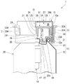
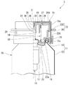
도 1은 본 발명의 제1 실시형태에 관한 토출 용기의 주요부에 대한 반쪽 종단면도로서, 내부판이 대기 위치에 위치하는 상태를 나타내는 도면이다.
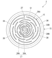
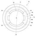
도 2는 도 1에 도시한 토출 용기의 상면도이다.
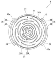
도 3은 도 2에 도시한 토출 용기의 내부판을 나타내는 상면도이다.
도 4는 도 1에 도시한 토출 용기의 주요부에 대한 반쪽 종단면도로서, 내부판을 토출 위치로 하강시킨 상태를 나타내는 도면이다.
도 5는 본 발명의 제2 실시형태에 관한 토출 용기의 주요부에 대한 반쪽 종단면도로서, 내부판이 대기 위치에 위치하는 상태를 나타내는 도면이다.
도 6은 도 5에 도시한 토출 용기의 상면도이다.
도 7은 도 6에 도시한 토출 용기의 내부판을 나타내는 상면도이다.
도 8은 본 발명의 제3 실시형태에 관한 토출 용기의 주요부에 대한 반쪽 종단면도로서, 내부판이 대기 위치에 위치하는 상태를 나타내는 도면이다.
도 9는 본 발명의 제4 실시형태에 관한 토출 용기의 주요부에 대한 반쪽 종단면도로서, 내부판이 대기 위치에 위치하는 상태를 나타내는 도면이다.
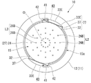
도 10은 도 9에 도시한 토출 용기의 상면도이다.
도 11은 도 10에 도시한 토출 용기의 내부판을 나타내는 상면도이다.
도 12는 본 발명의 제5 실시형태에 관한 토출 용기의 주요부에 대한 반쪽 종단면도로서, 내부판이 대기 위치에 위치하는 상태를 나타내는 도면이다.
도 13은 도 12에 도시한 토출 용기의 상면도이다.
도 14는 도 13에 도시한 토출 용기의 내부판을 나타내는 상면도이다.
도 15는 본 발명의 제6 실시형태에 관한 토출 용기의 주요부에 대한 반쪽 종단면도로서, 내부판이 대기 위치에 위치하는 상태를 나타내는 도면이다.
도 16은 도 15에 도시한 토출 용기의 상면도이다.
도 17은 도 16에 도시한 토출 용기의 내부판을 나타내는 상면도이다.
도 18은 본 발명의 실시형태에 관한 토출 용기의 주요부에 대한 반쪽 종단면도로서, 내부판이 대기 위치에 위치하는 상태를 나타내는 도면이다.
도 19는 도 18에 도시한 토출 용기의 상면도로서, 외장부를 위에서 본 도면이다.
도 20은 도 18에 도시한 토출 용기의 내부판의 주요부를 나타내는 종단면도이다.
도 21은 도 18에 도시한 토출 용기의 주요부에 대한 반쪽 종단면도로서, 누름판을 사용 자세로 한 상태를 나타내는 도면이다.
도 22는 도 21에 도시한 토출 용기의 상면도로서, 외장부를 위에서 본 도면이다.
도 23은 도 21에 도시한 토출 용기의 주요부에 대한 반쪽 종단면도로서, 내부판을 토출 위치에 하강시킨 상태를 나타내는 도면이다. Brief Description of the Drawings Fig. 1 is a half vertical sectional view of a main portion of a discharge container according to a first embodiment of the present invention, showing a state in which an inner plate is positioned at a standby position. Fig.
2 is a top view of the discharge container shown in Fig.
3 is a top view showing the inner plate of the discharge container shown in Fig.
Fig. 4 is a half vertical sectional view of the main part of the discharge container shown in Fig. 1, showing a state in which the inner plate is lowered to the discharge position. Fig.
Fig. 5 is a half vertical sectional view of a main portion of a discharge container according to a second embodiment of the present invention, showing a state in which the inner plate is positioned at the standby position. Fig.
6 is a top view of the discharge container shown in Fig.
7 is a top view showing an inner plate of the discharge container shown in Fig.
8 is a half vertical sectional view of a main portion of a discharge container according to a third embodiment of the present invention, showing a state in which the inner plate is positioned at the standby position.
9 is a half vertical sectional view of a main part of a discharge container according to a fourth embodiment of the present invention, showing a state in which an inner plate is positioned at a standby position.
10 is a top view of the discharge container shown in Fig.
11 is a top view showing an inner plate of the discharge container shown in Fig.
Fig. 12 is a half vertical sectional view of a main part of a discharge container according to a fifth embodiment of the present invention, showing a state in which the inner plate is positioned at the standby position. Fig.
13 is a top view of the discharge container shown in Fig.
14 is a top view showing the inner plate of the discharge container shown in Fig.
Fig. 15 is a half vertical sectional view of a main part of a discharge container according to a sixth embodiment of the present invention, showing a state in which the inner plate is positioned at the standby position. Fig.
16 is a top view of the discharge container shown in Fig.
17 is a top view showing the inner plate of the discharge container shown in Fig.
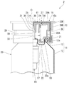
Fig. 18 is a half vertical sectional view of a main part of a discharge container according to an embodiment of the present invention, showing a state in which an inner plate is positioned at a standby position. Fig.
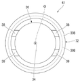
Fig. 19 is a top view of the discharge container shown in Fig. 18, showing the exterior of the discharge container from above.
20 is a vertical sectional view showing a main part of the inner plate of the discharge container shown in Fig.
Fig. 21 is a half vertical sectional view of the main part of the discharge container shown in Fig. 18, showing a state in which the pressure plate is in the used posture. Fig.
Fig. 22 is a top view of the discharge container shown in Fig.
Fig. 23 is a half vertical sectional view of the main part of the discharge container shown in Fig. 21, showing a state in which the inner plate is lowered to the discharge position. Fig.
(제1 실시형태)(First Embodiment)
이하에서는 도면을 참조하여, 본 발명의 제1 실시형태에 관한 토출 용기를 설명한다.Hereinafter, a discharge container according to a first embodiment of the present invention will be described with reference to the drawings.
도 1 내지 도 4에 도시한 바와 같이, 토출 용기(1)는 용기체(11)와, 토출기(14)와, 외장부(15)와, 내부판(61)을 구비한다. 토출 용기(10)는 예를 들어, 거품체나 고점성 재료 등, 토출 후에 적어도 일정 시간에 걸체 형상을 유지 가능한 내용물을 토출한다. 용기체(11)는 내용물이 수용되는 용기 본체(12)와, 용기 본체(12)의 입구부(12a)에 장착된 고정부재(13)를 구비한다. 1 to 4, the
여기서, 본 실시형태에서는 용기 본체(12)는 바닥이 있는 통 형태로 형성되고, 외장부(15)는 천정이 있는 통 형태로 형성되어 있어, 이들의 각 중심축은 공통 축 상에 배치되어 있다. 이하, 이 공통 축을 용기 축(O)이라 하고, 용기 축(O)을 따른 방향 중, 용기 본체(12)의 바닥측을 하측이라 하고, 용기 본체(12)의 입구부(12a)측을 상측이라 하고, 용기 축(O)을 따른 방향을 상하 방향이라 한다. 토출 용기(10)를 상면에서 봤을 때, 용기 축(O)과 직교하는 방향을 지름 방향이라 하고, 용기 축(O) 주위를 주회하는 방향을 둘레 방향이라 한다. Here, in the present embodiment, the
용기 본체(12)는 이 용기 본체(12)의 입구부(12a)가 정벽(17)으로 덮여짐으써 밀폐되어 있다. 정벽(17)에는 둘레 방향으로 연장하는 환상 오목부(18)가 형성되어 있다. 환상 오목부(18)는 하측을 향해 오목하게 들어가 있다. The
토출기(14)는 용기 본체(12)의 입구부(12a)에 상방 가압 상태에서 하향 이동 가능하게 세워 설치된 스템(19)을 갖추고 있다. 스템(19)은 용기 축(O)과 동축에 배치되어, 환상 오목부(18)보다도 작은 직경으로 형성되어 있다. 스템(19)은 정벽(17)을 상하 방향으로 관통한다. 토출기(14) 내부에 있어서, 용기 본체(12) 내에 위치하는 부분에는 도시하지 않은 토출 밸브가 설치되어 있다. The
용기 본체(12)에 대해서 스템(19)이 눌려지면, 토출 밸브가 열리고, 용기 본체(12) 내의 내용물이 스템(19) 내를 통하여 스템(19)의 상단부에서 토출된다. 이 때, 본 실시형태에서는 스템(19)의 상단부로부터, 예를 들어, 거품 형태가 된 용기 본체(12) 내의 내용물이 토출된다. 스템(19)의 누름을 해제하면, 스템(19)에 작용하는 상방 가압력에 의해 스템(19)이 상승하는 동시에 토출 밸브가 닫혀져, 내용물의 토출이 정지된다. 또한, 상술한 용기 본체(12) 및 토출기(14)는 용기 본체(12) 내에 수용된 내용물을 스템(19)에서 토출하는 토출 용기 본체(20)를 구성한다. 도시한 예에서는 토출 용기 본체(20)로서, 내부에 액상 내용물이 수용된 에어졸 캔을 채용하고 있다. When the
고정부재(13)는 스템(19)을 지름 방향으로 외측에서 둘러싸도록 용기 본체(12)의 입구부(12a)에 고정된다. 고정부재(13)는 용기 축(O)과 동축의 다중 통 형태로 형성되어 있다. 고정부재(13)는 용기 본체(12)의 입구부(12a)에, 용기 축(O) 주위를 회전 불가능하게, 또한 상승 불가능하게 고정되어 있다. 고정부재(13)는 외통부(21)와, 내통부(22)와, 돌출부(23A)를 구비한다. The fixing
외통부(21)는 본 실시형태에서는 상측을 향해 개구하는 환상 홈을 갖는 2중 통 형태로 형성되어 있어, 외장부(15)의 주벽부(15a) 하단부는 환상 홈 내에 끼워맞춰져 있다. 외통부(21)를 상면에서 본 형태는 용기 축(O)과 동축의 원형으로 되어 있다. In the present embodiment, the
내통부(22)는 정벽(17)의 환상 오목부(18) 내에 끼워맞춰져 있다. 내통부(22)는 환상 오목부(18)에 있어서, 지름 방향으로 내측을 향하는 외주면에, 지름 방향으로 내측에서 끼워맞춰져 있다. 돌출부(23A)는 외통부(21)와 내통부(22)를 연결하여, 상측을 향해 돌출해 있고, 후술하는 토출 상태에 있어서, 돌출부(23A)의 외주면과 내부판 본체(30)의 내주면이 지름 방향으로 근접하는 위치에 배치되어 있다. The
외장부(15)는 스템(19)의 상측에 배치된 정상벽부(24)를 갖는다. 정상벽부(24)는 용기 축(O)과 직교하는 판상으로 형성되어 있다. 외장부(15)의 내주면을 상면에서 본 형상은 용기 축(O)과 동축의 원형으로 되어 있다. 외장부(15)는 용기 축(O)과 동축에 배치된 천정이 있는 원통형으로 형성되어 있다. 외장부(15)에는 심체(25)와, 성형 구멍(토출 구멍)(26A)과, 삽입 관통 구멍(29)이 형성되어 있다. 심체(25)는 정상벽부(24)에서 하측을 향해 연장해 있다. 심체(25)는 용기 축(O)과 동축에 배치되어 있다. 심체(25)는 스템(19)의 상단 가장자리보다도 상측에 위치해 있다. 심체(25)의 외부 직경은 스템(19)의 내부 직경보다도 작고, 심체(25)는 스템(19)의 상단부와 상하 방향으로 대향해 있다. 심체(25)는 단단한 봉 형태 또는 기둥 형태로 형성되어 있다. 심체(25)의 하단부에 지름 축소부가 형성되어 있다.The enclosure (15) has a top wall portion (24) arranged on the upper side of the stem (19). The
복수의 성형 구멍(26A)은 외장부(15)의 정상벽부(24)에 상하 방향으로 관통하여 형성되어 있다. 복수의 성형 구멍(26A)은 정상벽부(24)에 있어서 상측을 향하는 토출면(27) 및 정상벽부(24)에 있어서 하측을 향하는 공급면(28)에 각각 개구해 있다. 또한, 토출면(27) 및 공급면(28)은 용기 축(O)과 직교하는 방향으로 연장해 있다. The plurality of
성형 구멍(26A)은 둘레 방향으로 연장하는 긴 구멍 형태로 형성되어 있다. 복수의 성형 구멍(26A)은 둘레 방향 및 지름 방향으로 간격을 두고 배치되어 있다. 본 실시형태에서는 둘레 방향으로 간격을 두고 배치된 복수의 성형 구멍(26A)이 구멍열 L1을 형성하고 있고, 이 구멍열 L1이 용기 축(O)을 중심으로 하여 다중으로 배치되어 있다. 구멍열 L1은 상면에서 봤을 때, 심체(25)를 지름 방향으로 외측에서 둘러싸도록 배치되어 있다.The
삽입 관통 구멍(29)은 외장부(15)의 주벽부(15a)를, 주벽부(15a)의 하단측이 개구하도록 절결함으로써 형성되어, 외장부(15)를 지름 방향으로 관통하고 있다. 삽입 관통 구멍(29)은 내부판(61)의 후술하는 누름부(71)가 외장부(15)의 외측을 향해 돌출하도록 삽입 관통 가능한 위치 및 치수로 형성되어 있다. The
내부판(61)은 외장부(15) 내에 상하 이동이 자유롭게 설치되고, 또한 외장부(15)에 대해서 회전 이동이 규제되어 있다. 내부판(61)은 외장부(15) 내에 배치된 내부판 본체(30)와, 그 내측에 스템(19)이 진퇴하는 가이드통(31)과, 스템(19)에 걸려, 내부판(61)의 하강에 따라 스템(19)을 하강시키는 걸림부(36)와, 지름 방향으로 외측을 향해 돌출하는 누름부(71)를 구비한다. 내부판 본체(30)는 천정이 있는 통 형태로 형성되고, 외장부(15) 내에 상하 이동이 자유롭게 끼워맞춰져, 외주면이 외장부(15)의 내주면 위를 상하 방향으로 슬라이딩한다. 내부판 본체(30)의 상면에서 본 형상은 외장부(15)의 내주면에서의 상면에서 본 형상과 동등한 형상 또한 동등한 크기로 형성되어 있다. The inner plate (61) is vertically movable in the outer casing (15) and is restricted from rotating with respect to the outer casing (15). The
내부판 본체(30)에는 연통 구멍(34)이 형성되어 있다. 연통 구멍(34)은 내부판 본체(30)를 상하 방향으로 관통해 있다. 연통 구멍(34)은 용기 축(O)과 동축에 배치되어 있다. 연통 구멍(34)은 심체(25)보다도 큰 직경이 되고, 연통 구멍(34) 내에는 심체(25)가 삽입 관통된다. 연통 구멍(34)은 스템(19)의 외부 직경보다도 작은 직경이 된다. A
가이드통(31)은 내부판 본체(30)에서 하측을 향해 연장되고, 가이드통(31)은 용기 축(O)과 동축에 배치되어 있다.The
내부판(61)은 도 1에 도시한 바와 같은 공급면(28)에 맞닿거나 또는 근접하는 상방의 대기 위치와, 도 4에 도시한 바와 같은 스템(19)을 하강시켜, 스템(19)으로부터의 내용물을 확산실(35) 내로 공급하는 하방의 토출 위치와의 사이를 상하 이동한다. 도 1에 도시한 바와 같이, 내부판(61)이 대기 위치에 위치할 때에는 심체(25)가 연통 구멍(34)에 삽입 관통되어 있다. The
도 4에 도시한 바와 같이, 내부판(61)은 토출 위치에 있어서, 공급면(28)에서 아래로 이격되어, 공급면(28)과의 사이에 확산실(35)을 형성한다. 확산실(35)은 스템(19)으로부터의 내용물을 정상벽부(24)에서의 하측을 향하는 공급면(28)과의 사이에, 지름 방향(토출면(27) 및 공급면(28)을 따르는 방향)으로 확산하여 복수의 성형 구멍(26A) 각각에 공급한다. 확산실(35)은 용기 축(O)과 동축에 배치되어 있다. 확산실(35)은 상하 방향보다도 지름 방향으로 큰 편평 형상으로 형성되어 있다. 확산실(35)의 벽면 일부는 공급면(28)에 의해 형성되어 있다. 4, the
내부판(61)에는 토출 위치에 위치할 때에, 스템(19)에 걸려, 스템(19)을 하강시키는 걸림부(36)가 설치되어 있다. 걸림부(36)는 내부판 본체(30)에서의 연통 구멍(34)의 개구 주연부에 위치하고, 스템(19)의 상단 가장자리에서 맞닿아, 스템(19)을 하강시킨다. 이 때, 연통 구멍(34)은 스템(19) 내와 확산실(35)을 연통해 있다. 또한, 이 때, 내부판(61)의 내부판 본체(30)가 심체(25)보다도 하측에 위치해 있어, 심체(25)는 확산실(35) 내에 배치되어 있다. The
도 1및 도 3에 도시한 바와 같이, 내부판(61)에는 지름 방향으로 외측을 향해 돌출하는 누름부(71)가 구비되어 있다. 누름부(71)는 표면 및 이면이 외장부(15)의 외주면을 따라 연장하는 측판(39A)과, 측판(39A)에서 지름 방향으로 외측을 향해 돌출하고, 또한 표면 및 이면이 상하 방향을 향하는 누름판(33A)과, 측판(39A)과 내부판 본체(30)를 연결하여 삽입 관통 구멍(29)에 삽입 관통된 연결판(38)을 구비하고 있다. 또한, 누름부(71)는 외장부(15)의 주벽부(15a)에 형성된 삽입 관통 구멍(29)을 통하여 외장부(15)의 지름 방향으로 외측에 배치되어 있다.As shown in Figs. 1 and 3, the
누름부(71)는 2개 구비되고, 내부판 본체(30)의 외주면에 있어서 용기 축(O)을 지름 방향으로 사이에 끼우는 위치에 각각 별도로 배치되어 있다. 연결판(38)은 내부판 본체(30)의 외주면 하단부에서 지름 방향으로 외측을 향해 돌출해 있다. 복수의(도시한 예에서는 2개) 연결판(38)은 둘레 방향으로 간격을 두고 배치되어 있다. 연결판(38)은 삽입 관통 구멍(29)에 삽입 관통된 상태로, 내부판 본체(30)와 측판(39A)을 연결하고 있다. 측판(39A)은 상하 방향으로 연장하여 배치되어 있다. 측판(39A)의 표면 및 이면은 외장부(15)의 외주면을 따라서 연장해 있다. 측판(39A)은 연결판(38)과 누름판(33A)을 연결하고 있다.Two
누름판(33A)은 측판(39A)의 상단부에서 지름 방향으로 외측을 향해 돌출해 있다. 누름판(33A)의 표면 및 이면은 상하 방향을 향해 있다. 누름판(33A)의 표면은 외장부(15)의 토출면(27)과 동일 평면으로 되어 있다. 또한, 누름판(33A)의 표면은 토출면(27)과 동일 평면으로 되어도 좋다.The
용기체(11)의 고정부재(13)와 내부판(61) 사이에는 스프링 부재로 이루어지는 가압 부재(50)가 설치되어 있다. 가압 부재(50)는 토출 위치에 위치하는 내부판(61)을 상방 가압하여 대기 위치까지 상승시킨다. 가압 부재(50)의 상단부는 내부판 본체(30)의 하면에 맞닿고, 가압 부재(50)의 하단부는 고정부재(13)의 내통부(22)에서 지름 방향으로 내측을 향해 돌출하는 플랜지부(22a)의 상면에 맞닿아 있다.A pressing
다음에, 본 실시형태에 관한 토출 용기(1)의 작용에 대해서 설명한다. Next, the operation of the
토출 용기(1)의 사용 전의 초기 상태에서는 내부판(61)이 도 1에 도시한 바와 같은 대기 위치에 배치되어 있다. 그리고 도 4에 도시한 바와 같이, 외장부(15)의 토출면(27)에 내용물을 토출시킬 때에, 누름판(33A)을 가압 부재(50)의 가압력에 저항하여 누름으로써, 외장부(15)의 정상벽부(24)와 내부판(61) 사이에 위치하는 확산실(35)의 내용적을 증대시키는 동시에, 내부판(61)의 걸림부(36)를 스템(19)의 상단부에 걸림 고정시킨다.In the initial state before use of the
또한, 내부판(61)의 하강에 따라, 걸림부(36)에 걸림 고정된 스템(19)이 상방 가압력에 저항하여 하강함으로써, 용기 본체(12) 내의 내용물이 스템(19)을 통하여 확산실(35)에 유입한다. 확산실(35)에 유입한 내용물은 정상벽부(24)에서의 아래를 향하는 공급면(28)과의 사이에, 확산실(35) 내에서 지름 방향으로 확산된 후에 복수의 성형 구멍(26A)에 공급되고, 이들 성형 구멍(26A)에서 토출면(27)에 토출된다.As the
여기서, 내용물이 복수의 성형 구멍(26A)을 각각 별도로 통과하여 성형되면, 복수의 조형편이 형성되고, 이들 조형편이 토출면(27) 상에서 조합됨으로써, 조형물이 형성된다. 또한, 성형 구멍(26A)에 의해 조형된 조형편은 성형 구멍(26A)이 연장하는 방향으로 길게 형성된다.Here, when the contents are formed by passing through the plurality of
그 후, 누름판(33A)의 누름 조작을 해제하면, 내부판(61)이 스템(19)의 상방을 향한 복원 변위에 따라, 외장부(15)에 대해서 상방으로 이동한다. 이 때, 확산실(35)의 내용적이 감소하여, 확산실(35)에 유입해 있던 내용물이 확산실(35)로부터 성형 구멍(26A)을 통하여 외부로 압출된다.Thereafter, when the pushing operation of the
이상에 설명한 바와 같이, 본 실시형태의 토출 용기(1)에 의하면, 내용물을 토출시킬 때에 누르는 누름부(71)가 내용물이 토출되는 토출면(27)을 갖는 외장부(15)와는 별도의 내부판(61)에 구비되어 있다. 이 때문에, 외장부(15)의 토출면(27)에 접촉하지 않고, 내용물을 토출시키는 것이 가능해져, 내용물이 손에 부착하는 것을 방지할 수 있다. 이에 더하여, 외장부(15)가 흔들리는 것이 억제되어, 토출면(27)으로부터 내용물이 흐르는 것을 방지할 수 있다. As described above, according to the
또한, 본 실시형태의 토출 용기(1)에서는 누름부(71)가 외장부의 외주면을 따라 연장하는 측판(39A)을 갖추고 있고, 지름 방향으로 외측을 향해 돌출하는 누름판(33A)이 측판(39A)을 통해 연결판(38)에 연결되어 있다. 그 때문에, 누름부(71)의 상하 방향의 굴곡 강성을 확보하기 쉬워져, 내구성을 향상시킬 수 있다. In the discharging
또한, 용기체(11) 내의 내용물이 확산실(35) 내에서 지름 방향으로 확산된 후에 토출 구멍(26A)에 공급된다. 그 때문에, 토출면(27)에 있어서 특정 일부에 배치된 토출 구멍(26A)에 내용물이 집중하는 것을 억제하여, 토출 구멍(26A)에 불균일이 적게 내용물을 공급할 수 있다. 이에 의해, 토출면(27)에 토출되는 내용물의 토출량이 위치마다 불균일하게 분포되는 것을 억제할 수 있다. Further, the contents in the
또한, 본 실시형태에서는 내부판(61)이 대기 위치에 위치하는 상태로부터, 누름판(33A)을 아래로 누름 조작하면, 내부판(61)은 가압 부재(50)에 의한 상방 가압력에 저항하여 하강하게 되어, 외장부(15)의 공급면(28)과 내부판(61) 사이에 형성되는 확산실(35)의 내용적이 증대되는 동시에, 내부판(61)의 걸림부(36)가 스템(19)에 걸린다. 더 누름 조작하여 내부판(61)을 하강시키면, 내부판(61)의 하강에 따라, 걸림부(36)가 스템(19)을 상방 가압력에 저항하여 하강시키고, 내부판(61)은 토출 위치에 배치되는 동시에, 용기 본체(12) 내의 내용물이 스템(19)을 통하여 확산실(35)에 유입한다.In the present embodiment, when the
그 후, 누름판(33A)의 누름 조작을 해제하면, 가압 부재(50)에 의한 내부판(61)의 상방 가압력 및 스템(19)의 상방 가압력에 의해, 내부판(61) 및 스템(19)이 상방 이동하여 복원 위치하게 되는 동시에, 내부판(61)이 대기 위치로 복귀된다. 이 때, 내부판(61)이 외장부(15)의 정상벽부(24)에 맞닿거나 또는 근접하는 것으로, 내부판(61)을 상승시키기 전에 확산실(35) 내에 내용물이 잔류해 있어도, 이 내용물이 확산실(35)로부터 토출면(27)에 압출된다. 즉, 누름판(33A)의 누름 조작을 해제함으로써, 내부판(61)이 상방의 초기 위치로 복원 변위한다. 이에 의해, 확산실(35) 내에 잔류해 있던 내용물을, 확산실(35)로부터 압출할 수 있으므로, 외장부(15) 내에서의 내용물의 잔량을 저감할 수 있다. 이와 같이, 외장부(15) 내에서의 내용물의 잔량을 저감하는 것으로, 예를 들어, 외장부(15) 내를 청정하게 유지하기 쉽게 하거나 할 수도 있다. The
또한, 본 발명의 기술적 범위는 상기 실시형태에 한정되지 않고, 본 발명의 취지를 벗어나지 않는 범위에서 여러 가지 변경을 가하는 것이 가능하다. The technical scope of the present invention is not limited to the above embodiment, and various modifications can be made without departing from the spirit of the present invention.
예를 들어, 상기 실시형태에 있어서는 누름부(71)가 내부판 본체(30)에 2개 배치되고, 연결판(38)이 하나의 누름판(33A)에 2개 배치되어 있는 구성을 나타내었지만, 이러한 구성에 한정되지 않는다. 예를 들어, 내부판 본체에 1 또는 3개 이상의 누름부를 배치하여도 좋고, 하나의 누름판에 1개 또는 3개 이상의 연결판을 배치하여도 좋다. 또한, 상기 실시형태에 있어서는 내부판(61)이 토출 위치에 위치해 있을 때에 확산실(35)이 형성되는 구성을 나타내었지만, 이러한 구성에 한정되지 않는다. 예를 들어, 내부판(61)이 대기 위치에 위치해 있거나, 토출 위치에 위치해 있거나 상관없이, 확산실이 항상 형성되어 있어도 좋고, 확산실이 없어도 좋다. 또한, 토출기(14)의 토출 밸브로서, 스템(19)의 한 번의 누름 조작에 의해 일정량의 내용물이 토출되는 정량 밸브를 채용해도 좋다. 이러한 경우에는, 내용물이 토출면(27)에 토출되었을 때에, 복수의 성형 구멍(26A)을 통해서 토출면(27) 상에서 토출물이 조합되어 형성되는 조형물을 정밀도 좋게 형성할 수 있다. For example, in the above embodiment, two
(제2 실시형태)(Second Embodiment)
다음에, 본 발명의 제2 실시형태에 관한 토출 용기를, 도 5 내지 도 7을 참조하여 설명한다. 또한, 이 제2 실시형태에 있어서는 제1 실시형태에서의 구성 요소와 동일한 부분에 대해서는 동일한 부호를 달아, 그 설명을 생략하고, 다른 점에 대해서만 설명한다. Next, a discharge container according to a second embodiment of the present invention will be described with reference to Figs. 5 to 7. Fig. In the second embodiment, the same components as those in the first embodiment are denoted by the same reference numerals, and a description thereof will be omitted, and only different points will be described.
도 5 내지 도 7에 도시한 바와 같이, 본 실시형태에 관한 토출 용기(2)에서는 누름부(72)에서의 측판(39) 및 누름판(33B)이 외장부(15)의 주벽부(15a)에서의 전체 둘레에 걸쳐 배치되어 있다. 본 실시형태의 토출 용기(2)에 의하면, 내용물을 토출할 때에, 토출 용기(2)의 둘레 방향의 방향을 바꿀 필요가 없어져, 우수한 조작성을 구비하도록 할 수 있다. 5 to 7, in the
(제3 실시형태)(Third Embodiment)
다음에 본 발명의 제3 실시형태에 관한 토출 용기를, 도 8을 참조하여 설명한다. 또한, 이 제3 실시형태에 있어서는 제2 실시형태에서의 구성 요소와 동일한 부분에 대해서는 동일한 부호를 달아 그 설명을 생략하고, 다른 점에 대해서만 설명한다.Next, a discharge container according to a third embodiment of the present invention will be described with reference to Fig. In the third embodiment, the same components as those in the second embodiment are denoted by the same reference numerals and the description thereof will be omitted, and only different points will be described.
도 8에 도시한 바와 같이, 본 실시형태에 관한 토출 용기(3)에서는 누름부(73)가 측판을 갖지 않고, 누름판(33C)이 연결판(38)의 지름 방향으로 외측 단에 직결되어 있다. 본 실시형태의 토출 용기(3)에 의하면, 누름부(73)가 측판을 갖고 있지 않기 때문에, 누름판(33C)을 누른 힘을, 직접 연결판(38)에 전달할 수 있음은 물론, 내부판(61)을 형성하는 수지의 양을 삭감할 수 있다. 8, in the discharging
(제4 실시형태)(Fourth Embodiment)
다음에 본 발명의 제4 실시형태에 관한 토출 용기를, 도 9 내지 도 11을 참조하여 설명한다. 또한, 이 제4 실시형태에 있어서는 제2 실시형태에서의 구성 요소와 동일한 부분에 대해서는 동일한 부호를 달아 그 설명을 생략하고, 다른 점에 대해서만 설명한다.Next, a discharge container according to a fourth embodiment of the present invention will be described with reference to Figs. 9 to 11. Fig. In the fourth embodiment, the same components as those in the second embodiment are denoted by the same reference numerals and the description thereof will be omitted, and only different points will be described.
도 9 내지 도 11에 도시한 바와 같이, 본 실시형태에 관한 토출 용기(4)의 누름부(74)는 연결판(38)의 지름 방향으로 외측 단에 연결된 파지통부(44)를 구비한다. 파지통부(44)는 용기 축(O)과 동축에 배치되어 있다. 파지통부(44)는 연결판(38)의 지름 방향으로 외측 단에서 지름 방향으로 외측을 향해 돌출하는 환상의 상부 플랜지부(44a)와, 상부 플랜지부(44a)의 외측 단에서 아래를 향해 연장되는 본체통(44b)과, 본체통(44b)의 하단에서 지름 방향으로 외측을 향해 돌출하는 환상의 하부 플랜지부(44c)를 구비한다. 본체통(44b)은 용기체 중, 용기 본체(12)의 하부를 제외한 전역을 지름 방향으로 외측에서 덮고 있다. 본 실시형태의 토출 용기(4)에 의하면, 내용물을 토출할 때에, 예를 들어, 상부 플랜지부(44a) 또는 하부 플랜지부(44c)를 누르는 조작 외에, 토출 용기(4)를 자립시킨 상태로, 본체통(44b)을 파지하여 하강시키는 조작에 의해서 내용물을 토출시킬 수 있다. 9 to 11, the
(제5 실시형태)(Fifth Embodiment)
다음에 본 발명의 제5 실시형태에 관한 토출 용기를, 도 12 내지 도 14를 참조하여 설명한다. 또한, 이 제5 실시형태에 있어서는 제1 실시형태에서의 구성 요소와 동일한 부분에 대해서는 동일한 부호를 달아 그 설명을 생략하고, 다른 점에 대해서만 설명한다.Next, a discharge container according to a fifth embodiment of the present invention will be described with reference to Figs. 12 to 14. Fig. In the fifth embodiment, the same components as those in the first embodiment are denoted by the same reference numerals and the description thereof will be omitted, and only different points will be described.
도 12 내지 도 14에 도시한 바와 같이, 본 실시형태에 관한 토출 용기(5)의 누름부(75)는 연결판(38)의 지름 방향으로 외측 단에 연결된 경사판(45)을 구비한다. 경사판(45)은 아래를 향함에 따라, 점차 지름 방향으로 외측을 향해 연장해 있다. 경사판(45)은 지름 방향으로 외측에서 보아 사각형의 형상을 나타내고, 그 중 2변이 둘레 방향으로 연장하고, 나머지 2변이 상하 방향으로 연장해 있다. 경사판(45)의 하단에는 지름 방향으로 외측을 향해 돌출하는 돌기부(45a)가 형성되어 있다. 본 실시형태의 토출 용기(5)에 의하면, 내용물을 토출할 때에, 용기 축(O)을 지름 방향으로 사이에 끼운 위치에 각각 별도로 배치된 한 쌍의 경사판(45)을, 지름 방향으로 사이에 끼우면서 누름부(75) 전체를 누를 수 있다. 따라서, 내용물의 토출 시에, 토출 용기(5)의 자세를 안정하게 할 수 있다. As shown in Figs. 12 to 14, the pushing
(제6 실시형태)(Sixth Embodiment)
다음에 본 발명의 제6 실시형태에 관한 토출 용기를, 도 15 내지 도 17을 참조하여 설명한다. 또한, 이 제6 실시형태에 있어서는 제5 실시형태에서의 구성 요소와 동일한 부분에 대해서는 동일한 부호를 달아 그 설명을 생략하고, 다른 점에 대해서만 설명한다.Next, a discharge container according to a sixth embodiment of the present invention will be described with reference to Figs. 15 to 17. Fig. In the sixth embodiment, the same components as those in the fifth embodiment are denoted by the same reference numerals and the description thereof will be omitted, and only different points will be described.
도 15 내지 도 17에 도시한 바와 같이, 본 실시형태에 관한 토출 용기(6)의 누름부(76)는 연결판(38)의 지름 방향으로 외측 단에 연결된 경사판(46)을 구비한다. 경사판(46)은 상측을 향함에 따라, 점차 지름 방향으로 외측을 향해 연장해 있다. 경사판(46)은 지름 방향으로 외측에서 보아 사각형의 형상을 나타내고, 이 중 2변이 둘레 방향으로 연장하고, 나머지 2변이 상하 방향으로 연장해 있다. 경사판(46)의 상단에는 지름 방향으로 외측을 향해 돌출하는 돌기부(46a)가 형성되어 있다. As shown in Figs. 15 to 17, the
(제7 실시형태)(Seventh Embodiment)
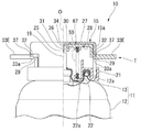
다음에 본 발명에 관한 제7 실시형태에 관한 토출 용기를, 도 18 내지 도 23을 참조하여 설명한다. 도 18 내지 도 23에 도시한 바와 같이, 토출 용기(10)는 용기체(11)와, 토출기(14)와, 외장부(15)와, 내부판(67)을 구비한다. 토출 용기(10)는 예를 들어, 거품체나 고점성 재료 등, 토출 후에 적어도 일정 시간에 걸쳐 형상을 유지 가능한 내용물을 토출한다. 용기체(11)는 내용물이 수용되는 용기 본체(12)와, 용기 본체(12)의 입구부(12a)에 장착된 고정부재(13)를 구비한다. 용기 본체(12)에는 외장부(15)를 외측에서 덮는 동시에, 용기 본체(12)에 이탈이 자유롭게 장착된 천정이 있는 통 형태의 캡(C)이 설치되어 있다.Next, a discharge container according to a seventh embodiment of the present invention will be described with reference to Figs. 18 to 23. Fig. 18 to 23, the discharging
여기서, 본 실시형태에서는 용기 본체(12)는 천정이 있는 통 형태로 형성되고, 외장부(15)는 천정이 있는 통 형태로 형성되어 있어, 이들 각 중심 축은 공통 축 상에 배치되어 있다. 이하, 이 공통 축을 용기 축(O)이라 하고, 용기 축(O)을 따르는 방향 중, 용기 본체(12)의 바닥부측을 하측이라 하고, 용기 본체(12)의 입구부(12a)측을 상측이라 하고, 용기 축(O)을 따르는 방향을 상하 방향이라 한다. 토출 용기(10)를 상면에서 봤을 때, 용기 축(O)과 직교하는 방향을 지름 방향이라 하고, 용기 축(O) 주위를 주회하는 방향을 둘레 방향이라 한다.Here, in the present embodiment, the
용기 본체(12)는 이 용기 본체(12)의 입구부(12a)가 정벽(17)으로 덮여짐으로써 밀폐되어 있다. 정벽(17)에는 둘레 방향으로 연장하는 환상 오목부(18)가 형성되어 있다. 환상 오목부(18)는 하측을 향해 오목하게 들어가 있다. The
토출기(14)는 용기 본체(12)의 입구부(12a)에 상방 가압 상태에서 하향 이동 가능하게 세워 설치된 스템(19)을 구비한다. 스템(19)은 용기 축(O)과 동축으로 배치되고, 환상 오목부(18)보다도 작은 직경으로 형성되어 있다. 스템(19)은 정벽(17)을 상하 방향으로 관통해 있다. 토출기(14)의 내부에 있어서, 용기 본체(12) 내에 위치하는 부분에는 도시하지 않은 토출 밸브가 설치되어 있다. The
용기 본체(12)에 대해서 스템(19)이 눌러지면, 토출 밸브가 열리고, 용기 본체(12) 내의 내용물이 스템(19) 내를 통과하여 스템(19)의 상단부에서 토출된다. 이 때, 본 실시형태에서는 스템(19)의 상단부로부터, 예를 들어, 거품 형태가 된 용기 본체(12) 내의 내용물이 토출된다. 스템(19)의 누름을 해제하면, 스템(19)에 작용하는 상방 가압력에 의해 스템(19)이 상승하는 동시에, 토출 밸브가 닫혀, 내용물의 토출이 정지된다. 또한, 상술한 용기 본체(12) 및 토출기(14)는 용기 본체(12) 내에 수용된 내용물을 스템(19)으로부터 토출하는 토출 용기 본체(20)를 구성한다. 도시한 예에서는 토출 용기 본체(20)로서, 내부에 액상 내용물이 수용된 에어졸 캔을 채용하고 있다.When the
고정부재(13)는 스템(19)을 지름 방향으로 외측에서 둘러싸도록 용기 본체(12)의 입구부(12a)에 고정된다. 고정부재(13)는 용기 축(O)과 동축으로 다중 통 형태로 형성되어 있다. 고정부재(13)는 용기 본체(12)의 입구부(12a)에 용기 축(O) 주위를 회전 불가능하게, 또한 상승 불가능하게 고정되어 있다. 고정부재(13)는 외통부(21)와, 내통부(22)와, 연결부(23B)를 구비한다. The fixing
외통부(21)는 본 실시형태에서는 상측을 향해 개구하는 환상 홈을 갖는 2중 통 형태로 형성되어 있어, 외장부(15)의 주벽부(15a) 하단부는 상기 환상 홈 내에 끼워맞춰져 있다. 도시한 예에서는 외장부(15)는 외통부(21) 내측에 외장부(15)의 주벽부(15a)가 끼워 맞춰짐으로써, 고정부재(13)에 대해 용기 축(O) 주위를 회전 이동 가능하게 배치되고, 또한 고정부재(13)에 대한 상승 이동이 규제되어 있다. 외통부(21)를 상하 방향에서 본 상면도 형상은 용기 축(O)과 동축의 원형으로 되어 있다. In the present embodiment, the
내통부(22)는 정벽(17)의 환상 오목부(18) 내에 끼워맞춰져 있다. 내통부(22)는 환상 오목부(18)에 있어서, 지름 방향으로 내측을 향하는 외주면에, 지름 방향으로 내측에서 끼워맞춰져 있다. 내통부(22)의 상단부는 외통부(21)의 상단부보다도 상측에 위치해 있다. 연결부(23B)는 용기 본체(12)의 입구부(12a) 상측에 배치되어 있다. 연결부(23B)는 내통부(22)에서의 상하 방향의 중간부와, 외통부(21)의 상단부를 연결하고 있다. The
외장부(15)는 스템(19)의 상방에 배치된 정상벽부(24)를 갖는다. 정상벽부(24)는 용기 축(O)과 직교하는 판상으로 형성되어 있다. 외장부(15)의 내주면을 상면에서 본 형상은 용기 축(O)과 동축의 원형으로 되어 있다. The
외장부(15)에는 심체(25)와, 토출 구멍(26B)과, 삽입 관통 구멍(29)이 형성되어 있다. 심체(25)는 정상벽부(24)에서 하측을 향해 연장해 있다. 심체(25)는 상하 방향으로 연장하여, 용기 축(O)과 동축에 배치되어 있다. 심체(25)는 스템(19)의 상단 가장자리보다도 상측에 위치해 있다. 심체(25)의 외부 직경은 스템(19)의 내부 직경보다도 작고, 심체(25)는 스템(19)의 상단부와 상하 방향으로 대향해 있다. 심체(25)는 단단한 봉 형태, 기둥 형태로 형성되어 있다. 심체(25)는 상하 방향의 전체 길이에 걸쳐 동일 직경으로 형성되어 있다. A
토출 구멍(26B)은 외장부(15)의 정상벽부(24)에 상하 방향으로 관통하여 복수 형성되어 있다. 복수의 토출 구멍(26B)은 정상벽부(24)에 있어서 상측을 향하는 토출면(27), 및 정상벽부(24)에 있어서 하측을 향하는 공급면(28)에 각각 별도로 개구해 있다. 또한, 토출면(27) 및 공급면(28)은 용기 축(O)과 직교하는 방향으로 연장해 있다. A plurality of discharge holes 26B are formed in the
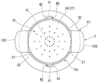
토출 구멍(26B)은 상면에서 보아 원형으로 형성되어 있다. 복수의 토출 구멍(26B)은 정상벽부(24)에 용기 축(O)을 중심으로 하여 방사상을 이루도록, 간격을 두고 배치되어 있다. 본 실시형태에서는 정상벽부(24)에 둘레 방향으로 간격을 두고 배치된 복수의 토출 구멍(26B)이 구멍열 L2(도 19를 참조)를 형성하고 있고, 이 구멍열 L2가 용기 축(O)을 중심으로 하여 다중으로 배치되어 있다. 구멍열 L2는 정상벽부(24)를 상하 방향에서 본 상면도에 있어서, 심체(25)를 지름 방향으로 외측에서 둘러싸도록 배치되어 있다. The
여기서, 용기체(11)의 고정부재(13)에는 도 18 및 도 19에 도시한 바와 같이, 외장부(15)의 주벽부(15a)와의 사이에 간극(43)이 형성된 상태로, 규제벽(41)이 배치되어 있다. 규제벽(41)에서의 둘레 방향의 한쪽 단부에는 지름 방향으로 내측을 향해 돌출하여, 고정부재(13)에 연결하는 위치 결정벽(42)이 형성되어 있다. 도시한 예에서는 규제벽(41) 및 위치 결정벽(42)은 고정부재(13)의 하단에서 삽입 관통 구멍(29)보다도 상측의 위치까지 상하 방향으로 연재한다. 규제벽(41)의 하단은 2중 통 형태로 형성된 외통부(21) 중 외통 부분의 하단부에 연결되어 있다. 위치 결정벽(42)의 하단은 외통부(21)에 연결되어 있다. 간극(43)은 후술하는 내부판(67)의 누름판(33E) 중 적어도 일부가 진입 가능한 크기로 형성되어 있다. 18 and 19, a
삽입 관통 구멍(29)은 외장부(15)의 주벽부(15a)를, 주벽부(15a)의 하단측이 개구하도록 절결함으로써 형성되어, 외장부(15)를 지름 방향으로 관통한다. 삽입 관통 구멍(29)은 내부판(67)의 일부(후술하는 걸림 돌기부(32) 및 누름판(33E))가 외장부(15)의 외측을 향해 돌출하도록 삽입 관통 가능한 위치 및 치수로 형성되어 있다. 삽입 관통 구멍(29)의 상하 방향을 따르는 절입 치수는 누름판(33E)이 간극(43)에서 벗어나 위치에 있어서, 적어도 내부판(67)이 후술하는 대기 위치와 토출 위치 사이를 상하 이동 가능한 치수로 설정되어 있다. The
내부판(67)은 외장부(15) 내에 상하 이동이 자유롭게 설치됨과 더불어, 외장부(15)에 대해서 회전 이동이 규제되어 있다. 내부판(67)은 내부판 본체(30)와, 가이드통(31)과, 걸림부(36)와, 누름부(77)를 구비한다. 내부판 본체(30)는 천정이 있는 통 형태로 형성되고, 외장부(15) 내에 끼워맞춰져, 외주연이 외장부(15)의 내주면 위를 상하 방향으로 슬라이딩한다. 내부판 본체(30)는 외장부(15)의 내주면에서의 상부에 끼워맞춰져 있다. 내부판 본체(30)의 상면에서 본 형상은 외장부(15)의 내주면 상부에서의 상면에서 본 형상과, 동등한 형상으로 또한 동등한 크기로 형성되어 있다. The
내부판 본체(30)에는 연통 구멍(34)이 형성되어 있다. 연통 구멍(34)은 내부판 본체(30)를 상하 방향으로 관통해 있다. 연통 구멍(34)은 용기 축(O)과 동축에 배치되어 있다. 연통 구멍(34)은 심체(25)보다도 큰 직경이 되고, 연통 구멍(34) 내에는 심체(25)가 관통된다. 연통 구멍(34)은 스템(19)의 외부 직경보다도 작은 직경으로 되어 있다. A
가이드통(31)은 내부판 본체(30)에서 하측을 향해 연장하여, 그 내측에 스템(19)이 진퇴한다. 가이드통(31)은 용기 축(O)과 동축에 배치되어 있다. 가이드통(31)은 스템(19)에 용기 축(O) 주위를 상대적으로 회전 가능하게 외부에서 삽입된다. The
내부판(67)은 도 21 및 도 22에 도시한 바와 같은 공급면(28)에 맞닿거나 또는 근접하는 상방의 대기 위치와, 도 23에 도시한 바와 같은 스템(19)을 하강시켜 스템(19)으로부터의 내용물을 확산실(35) 내에 공급하는 하방의 토출 위치와의 사이를 상하 이동한다. 도 21 및 도 22에 도시한 바와 같이, 내부판(67)이 대기 위치에 위치할 때에는 심체(25)가 연통 구멍(34)에 삽입 관통되어 있다. The
도 23에 도시한 바와 같이, 내부판(67)은 토출 위치에 있어서, 공급면(28)에서 아래로 이격하여, 공급면(28)과의 사이에 확산실(35)을 형성한다. 확산실(35)은 스템(19)으로부터의 내용물을 내부판(67)과, 정상벽부(24)에서의 하측을 향하는 공급면(28)과의 사이에 지름 방향(토출면(27) 및 공급면(28)을 따르는 방향)으로 확산하여 복수의 토출 구멍(26B) 각각에 공급한다. 확산실(35)은 용기 축(O)과 동축에 배치되어 있다. 확산실(35)은 상하 방향보다도 지름 방향으로 큰 편평 형상으로 형성되어 있다. 확산실(35) 벽면의 일부는 공급면(28)에 의해 형성되어 있다. 23, the
내부판(67)에는 상기 토출 위치에 위치할 때에, 스템(19)에 걸려, 스템(19)을 하강시키는 걸림부(36)가 설치되어 있다. 걸림부(36)는 내부판 본체(30)에서의 연통 구멍(34)의 개구 주연부에 위치하고, 내부판(67)의 하강에 따라서 스템(19)의 상단 가장자리에 상측에서 맞닿아, 스템(19)을 하강시킨다. 이 때, 연통 구멍(34)은 스템(19) 내와 확산실(35)을 연통하고 있다. 또한, 이 때에, 내부판(67)의 내부판 본체(30)가 심체(25)보다도 하측에 위치해 있고, 심체(25)는 확산실(35) 내에 배치되어 있다. The
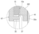
도 18 및 도 20에 도시한 바와 같이, 내부판(67)에는 지름 방향으로 외측을 향해 돌출하는 누름부(77)가 구비되어 있다. 누름부(77)는 외장부(15)의 주벽부(15a)에 형성된 삽입 관통 구멍(29)을 통과하여 외장부(15)의 지름 방향으로 외측에 배치되어 있고, 걸림 돌기부(32)와, 힌지부(37)와, 누름판(33E)을 구비한다.As shown in Figs. 18 and 20, the
한 쌍의 걸림 돌기부(32)가 내부판 본체(30)에서 지름 방향으로 외측을 향해 돌출해 있다. 한 쌍의 걸림 돌기부(32)는 용기 축(O)을 사이에 끼워 서로 마주보는 위치에 설치되어 있다. 걸림 돌기부(32)는 외장부(15)의 삽입 관통 구멍(29)을 통과하여, 외장부(15)의 외측을 향해서 돌출해 있다. A pair of latching protrusions (32) protrude outward in the radial direction from the inner plate main body (30). The pair of latching
누름판(33E)은 상하 방향으로 연장하고, 또한 하단부가 힌지부(37)를 통해서 걸림 돌기부(32)에 연결되어, 표면 및 이면이 지름 방향을 향하도록 배치되어 있다. 누름판(33E)은 외장부(15)의 주벽부(15a)에 형성된 삽입 관통 구멍(29)을 통과하여 외장부(15)의 외측에 배치되고, 표면 및 이면이 상하 방향을 향하는 사용 자세 T(도 21~23을 참조)가 되도록 힌지부(37) 주위에 이동이 자유롭게 배치되어 있다. 즉, 누름판(33E)은 사용 자세 T에 있어서, 외부에서 누르기 가능하게 설치되고, 걸림 돌기부(32)에서 지름 방향으로 외측을 향해 돌출해 있다. 또한, 누름판(33E)의 하단부에는 사용 자세 T일 때, 걸림 돌기부(32)의 하면에 걸리는 피걸림 돌기부(33a)가 형성되어 있다. The
내부판(67)은 누름판(33E)이 규제벽(41) 내측에 형성되는 간극(43)에 대해서 진퇴하도록, 용기체(11)에 대해서 둘레 방향으로 회전이 자유롭게 배치되고, 또한 외장부(15)에 대한 내부판(67)의 둘레 방향으로 회전 이동이 규제되어 있다. 즉, 내부판(67)과 외장부(15)는 둘레 방향으로 함께 회전한다.The
용기체(11)의 고정부재(13)와 내부판(67) 사이에는 스프링 부재로 이루어진 가압 부재(50)가 설치되어 있다. 가압 부재(50)는 토출 위치에 위치하는 내부판(67)을 상방 가압하여 대기 위치까지 상승시킨다. 가압 부재(50)의 상단부는 내부판 본체(30)의 하면에 맞닿고, 가압 부재(50)의 하단부는 고정부재(13)의 내통부(22)에서 지름 방향으로 내측을 향해 돌출하는 플랜지부(22a)의 상면에 맞닿아 있다. A pressing
다음에 본 실시형태에 관한 토출 용기(10)의 작용에 대해서 설명한다. Next, the operation of the
토출 용기(10)의 사용 전 초기 상태에서는 내부판(67)이 도 18에 도시한 바와 같은 대기 위치에 배치되고, 누름판(33E)이 표면 및 이면이 지름 방향을 향하는 자세로, 외장부(15)의 주벽부(15a)와 규제벽(41) 사이의 간극(43)에 진입한 상태로 배치되어 있다. 이 때, 주벽부(15a)와 규제벽(41)에 의해서, 누름판(33E)의 지름 방향에의 이동이 규제되고, 또한 위치 결정벽(42)에 의해 누름판(33E)의 둘레 방향으로 한쪽(누름판(33E)이 간극(43)에 진입하는 방향)으로의 이동이 규제되어 있다. In the initial state before use of the
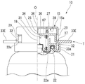
도 21에 도시한 바와 같이, 외장부(15)의 토출면(27)에 내용물을 토출시킬 때에, 내부판(67)을 외장부(15)와 함께 용기체(11)에 대해서 둘레 방향으로 다른 쪽으로 회전시켜 누름판(33E)을 규제벽(41)과 외장부(15)의 주벽부(15a) 사이의 간극(43)에서 벗어나는 위치로 이동시키고, 누름판(33E)을 표면 및 이면이 상하 방향을 향하도록 힌지부(37) 주위로 이동시켜서 사용 자세 T로 한다. 그리고 도 23에 도시한 바와 같이, 이 사용 자세 T에 있는 누름판(33E)을 누름으로써, 외장부(15)의 정상벽부(24)와 내부판(67) 사이에 위치하는 확산실(35)의 내용적을 증대시키는 동시에, 내부판(67)의 걸림부(36)를 스템(19)의 상단부에 걸리게 한다. 21, when the contents are discharged onto the discharging
또한, 내부판(67)의 하강에 따라, 걸림부(36)에 걸려진 스템(19)이 상방 가압력에 저항하여 하강함으로써, 용기 본체(12) 내의 내용물이 스템(19)을 통과하여 확산실(35)에 유입한다. 확산실(35)에 유입한 내용물은 내부판(67)과, 정상벽부(24)에서의 하측을 향하는 공급면(28)과의 사이에, 확산실(35) 내에서 지름 방향으로 확산된 후에 복수의 토출 구멍(26B)에 공급되고, 이들 토출 구멍(26B)에서 토출면(27)에 토출된다. 그 후, 누름판(33E)의 누름 조작을 해제하면, 내부판(67)이 스템(19)의 상방을 향한 복원 변위에 따라, 외장부(15)에 대해서 상방 이동한다. 이 때, 확산실(35)의 내용적이 감소하고, 확산실(35)에 유입해 있던 내용물이 확산실(35)에서 토출 구멍(26B)을 통하여 외부로 압출된다. As the
이상에 설명한 바와 같이, 본 실시형태의 토출 용기(10)에 의하면, 용기 본체(12) 내의 내용물이 확산실(35) 내에서 지름 방향으로 확산된 후에 복수의 토출 구멍(26B)에 공급된다. 그 때문에, 토출면(27)에 있어서, 특정한 일부에 배치된 토출 구멍(26B)에 내용물이 집중하는 것을 억제하여, 토출 구멍(26B)에 불균일 적게 내용물을 공급할 수 있다. 이에 의해, 토출면(27)에 토출되는 내용물의 토출량이 위치마다 불균일하게 분포되는 것을 억제할 수 있다. As described above, according to the
또한, 본 실시형태의 토출 용기(10)에서는 내용물을 토출시킬 때에만, 누름판(33E)을 사용 자세로 한다. 그 때문에, 토출 용기(10)를, 예를 들어, 유통 단계 등과 같이 사용하지 않을 때에, 누름판(33E)을, 표면 및 이면이 지름 방향을 향하는 자세로 규제벽(41)과 외장부(15)의 주벽부(15a) 사이의 간극(43)에 진입시켜 수용해 둘 수 있다. 그 때문에, 토출 용기(10)를 사용하지 않을 때의 지름 방향 치수를 작게 억제할 수 있다. In the discharging
한편으로, 사용 시의 누름판(33E)의 지름 방향으로 외측에의 돌출 길이를 크게 하는 것이 가능하다. 그 때문에, 누름판(33E)의 아래로의 누름을 용이하게 할 수 있다. 또한, 누름판(33E)을 사용 자세 T로 하면, 걸림 돌기부(32)의 하면에 누름판(33E)의 피걸림 돌기부(33a)가 걸려, 누름판(33E)의 힌지부(37) 주위의 아래를 향한 회전이 규제된다. 그 때문에, 누름판(33E)의 누름에 의해 내부판(67)을 확실하게 하강시킬 수 있다. On the other hand, it is possible to increase the projecting length to the outside in the radial direction of the
또한, 본 실시형태에서는 내부판(67)이 대기 위치에 위치하는 상태에서, 누름판(33E)을 아래로 누름 조작하면, 내부판(67)은 가압 부재(50)에 의한 상방 가압력에 저항하여 하강시키고, 외장부(15)의 공급면(28)과 내부판(67) 사이에 형성되는 확산실(35)의 내용적이 증대됨은 물론, 내부판(67)의 걸림부(36)가 스템(19)에 걸림 고정된다. 더 누름 조작하여 내부판(67)을 하강시키면, 내부판(67)의 하강에 따라, 걸림부(36)가 스템(19)을 상방 가압력에 저항하여 하강시켜, 내부판(67)은 토출 위치에 배치되는 동시에, 용기 본체(12) 내의 내용물이 스템(19)을 통과하여 확산실(35)에 유입한다.In this embodiment, when the
그 후, 누름판(33E)의 누름 조작을 해제하면, 가압 부재(50)에 의한 내부판(67)의 상방 가압력 및 스템(19)의 상방 가압력에 의해, 내부판(67) 및 스템(19)이 상방 이동하여 복원 변위하게 되는 동시에, 내부판(67)이 대기 위치로 되돌아간다. 이 때, 내부판(67)이 외장부(15)의 정상벽부(24)에 맞닿거나 또는 근접하는 것으로, 내부판(67)을 상승시키기 전에 확산실(35) 내에 내용물이 잔류해 있어도, 이 내용물이 확산실(35)로부터 토출면(27)에 압출된다. 즉, 누름판(33E)의 누름 조작을 해제함으로써, 내부판(67)이 상방의 초기 위치로 복원 변위된다. 이로 인해, 확산실(35) 내에 잔류해 있던 내용물을 확산실(35)로부터 압출할 수 있으므로, 외장부(15) 내에서의 내용물의 잔량을 저감할 수 있다. 이와 같이, 외장부(15) 내에서의 내용물의 잔량을 저감하는 것으로, 예컨대, 외장부(15) 내를 청정하게 유지하기 쉽게 하거나 할 수 있다. The
또한, 본 발명의 기술적 범위는 상기 실시형태에 한정되지 않고, 본 발명의 취지를 벗어나지 않는 범위에 있어서 여러 가지 변경을 가할 수 있는 것이 가능하다. The technical scope of the present invention is not limited to the above-described embodiment, and various changes can be made within the scope of the present invention.
예를 들어, 상기 실시형태에서는 규제벽(41)의 둘레 방향으로 한쪽 단부에 위치 결정벽(42)을 설치한 구성으로 했지만, 이러한 구성에 한정되지 않는다. 예를 들어, 이 위치 결정벽(42)을 생략하는 것도 가능하다. 또한, 상기 실시형태에서는 내부판(67)이 외장부(15)에 대한 둘레 방향의 회전이 규제되고, 내부판(67)과 외장부(15)가 일체로 둘레 방향으로 함께 회전하는 구성으로 되어 있지만, 이와 같은 구성에 한정되지 않는다. 예를 들어, 내부판(67)이 용기체(11) 및 외장부(15)에 대해 둘레 방향으로 회전이 자유롭게 배치되어 있어도 좋다. For example, in the above embodiment, the
또한, 토출 용기는 단순히 내용물을 토출면(27) 상에 토출할뿐만 아니라, 토출면(27) 상에 조형물을 형성하는 것도 좋다. 예를 들어, 토출 용기에 의해 조형되는 조형물의 형상, 토출하는 내용물의 용도 등에 의해, 토출 구멍의 수나 형상을 적절히 변경하는 것이 가능하다. 예를 들어, 토출 구멍이 하나여도 좋다. It is also preferable that the ejection container not only ejects the contents onto the
상기 실시형태에서는 토출 용기 본체(20)로서 에어졸 캔을 채용하는 구성으로 했지만, 이와 같은 구성에 한정되지 않는다. 예를 들어, 토출 용기 본체(20)로서, 펌프 기구를 갖는 토출기(14)를 구비하는 구성을 채용하는 것도 가능하다. In the above embodiment, the aerosol can is employed as the discharge container
또한, 용기체(11)는 용기 본체(12)와 고정부재(13)가 별개로 설치되어 있지만, 용기 본체(12)와 고정부재(13)가 일체로 설치되어 있어도 좋다. 상기 실시형태에서는 규제벽(41) 및 위치 결정벽(42)이 고정부재(13)에 연결되어 있지만, 용기 본체(12)에 연결되어 있어도 좋다. Although the
그 외에, 본 발명의 취지를 벗어나지 않는 범위에서, 상기 실시형태에서의 구성 요소를 주지의 구성 요소로 치환하는 것은 적절히 가능하며, 또한 상기한 변형예를 적절히 조합해도 좋다.In addition, it is possible to appropriately replace the components in the above embodiments with known components, without departing from the spirit of the present invention, and the above-described modifications may be appropriately combined.
본 발명에 의하면, 내용물을 토출할 때에, 내용물이 손에 부착하거나, 흐르거나 하는 것을 억제할 수 있다. According to the present invention, when the contents are discharged, it is possible to prevent the contents from adhering to the hand or from flowing.
1, 2, 3, 4, 5, 6, 10 토출 용기
11 용기체
12a 입구부
14 토출기
15 외장부
15a 주벽부
19 스템
24 정상벽부
26A, 26B 토출 구멍
27 토출면
28 공급면
29 삽입 관통 구멍
30 내부판 본체
32 걸림 돌기부
33A, 33B, 33C, 33D, 33E 누름판
35 확산실
36 걸림부
37 힌지부
38 연결판
39A, 39B 측판
41 규제벽
43 간극
50 가압 부재
61, 67 내부판
71, 72, 73, 74, 75, 76, 77 누름부
T 사용 자세1, 2, 3, 4, 5, 6, 10 Discharge container
11 gas
12a inlet portion
14 Discharger
15 Exterior
15a circumferential wall portion
19 stems
24 normal wall portion
26A, 26B Discharge hole
27 Discharge surface
28 Supply Side
29 Insertion hole
30 inner plate body
32 engaging projection
33A, 33B, 33C, 33D, 33E presser plates
35 Diffusion room
36,
37 Hinge section
38 connecting plate
39A, 39B shroud
41 regulating wall
43 Clearance
50 pressing member
61, 67 internal plate
71, 72, 73, 74, 75, 76, 77,
T posture
Claims (6)
상기 용기체의 입구부에 상방 가압 상태에서 하향 이동 가능하게 세워 설치된 스템을 갖는 토출기와,
상기 스템의 상방에 배치됨과 더불어, 토출 구멍이 상하 방향으로 관통하는 정상벽부를 가지고, 상기 정상벽부에서의 상방을 향하는 토출면에 상기 토출 구멍으로부터 내용물을 토출하는 외장부와,
상기 외장부 내로 이동이 자유롭게 설치된 내부판을 구비하고,
상기 외장부는 상기 용기체에 장착되고,
상기 내부판에는 상기 스템에 걸려, 상기 내부판의 하강에 따라 상기 스템을 하강시키는 걸림부가 설치됨은 물론, 지름 방향으로 외측을 향해 돌출하는 누름부가 구비되고,
상기 누름부는 상기 외장부의 주벽부에 형성된 삽입 관통 구멍을 통과하여 상기 외장부의 외측에 배치되어 있는 토출 용기.
A container for containing the contents,
A discharge unit having a stem installed upright at an inlet portion of the container body so as to be downwardly movable in an upwardly pressurized state,
An outer casing that is disposed above the stem and has a top wall portion through which the discharge hole vertically penetrates and discharges the content from the discharge hole to a discharge surface facing upward in the top wall portion;
And an inner plate provided so as to be movable into the outer casing,
The outer casing is mounted on the casing,
The inner plate is provided with a latching portion for hanging the stem and lowering the stem according to the descent of the inner plate, a pushing portion protruding outward in the radial direction,
And the pushing portion is disposed on the outer side of the outer casing through the insertion hole formed in the peripheral wall of the outer casing.
The press machine according to claim 1, wherein the inner plate has an inner plate main body disposed in the outer casing, the pressing portion includes a side plate having a front surface and a rear surface extending along an outer peripheral surface of the outer casing, And a connecting plate connected to the side plate and the inner plate body so as to be inserted into the insertion through hole.
The discharge container according to claim 1 or 2, wherein the pressure plate is disposed over the entire circumference of the peripheral wall of the outer casing.
4. The apparatus according to any one of claims 1 to 3, wherein the inner plate diffuses the contents from the stem in a radial direction between the inner plate and the supply surface facing downward in the top wall portion, To form a diffusion chamber.
The apparatus according to claim 1, wherein the inner plate forms a diffusion chamber for diffusing the contents from the stem in the radial direction and supplying the contents to the discharge hole, between the supply plate and the supply surface facing downward in the top wall, The pressing portion includes a latching protrusion and a pressing plate extending in the vertical direction and connected to the latching protrusion via a hinge portion at a lower end thereof and having a front surface and a rear surface facing the diametrical direction, And the lower end of the pressing plate is provided with a hooking projection protruding from the lower surface of the latching protrusion when the lower surface of the pressing plate is in the use posture, And a regulating wall arranged in a state in which a clearance is formed between the container body and the circumferential wall of the outer casing, And, said inner plate, said pressure plate a discharge vessel, which is free to rotate disposed in the circumferential direction with respect to the base body for, so as to advance and retreat with respect to the gap.
Applications Claiming Priority (4)
| Application Number | Priority Date | Filing Date | Title |
|---|---|---|---|
| JP2015132115 | 2015-06-30 | ||
| JPJP-P-2015-254855 | 2015-12-25 | ||
| JP2015254855A JP6598677B2 (en) | 2015-06-30 | 2015-12-25 | Discharge container that discharges contents to discharge surface |
| PCT/JP2016/088423 WO2017111050A1 (en) | 2015-06-30 | 2016-12-22 | Discharge container for discharging contents onto discharge surface |
Publications (2)
| Publication Number | Publication Date |
|---|---|
| KR20180098552A true KR20180098552A (en) | 2018-09-04 |
| KR102606815B1 KR102606815B1 (en) | 2023-11-27 |
Family
ID=57829744
Family Applications (1)
| Application Number | Title | Priority Date | Filing Date |
|---|---|---|---|
| KR1020187017341A Active KR102606815B1 (en) | 2015-06-30 | 2016-12-22 | Discharge container that discharges contents onto the discharge surface |
Country Status (6)
| Country | Link |
|---|---|
| US (2) | US10569460B2 (en) |
| EP (1) | EP3395717B1 (en) |
| JP (1) | JP6598677B2 (en) |
| KR (1) | KR102606815B1 (en) |
| CA (1) | CA2952448C (en) |
| WO (1) | WO2017111050A1 (en) |
Families Citing this family (11)
| Publication number | Priority date | Publication date | Assignee | Title |
|---|---|---|---|---|
| EP3395718B1 (en) | 2015-12-25 | 2021-04-07 | Yoshino Kogyosho Co., Ltd. | Discharge container for discharging contents onto discharge surface |
| JP6721478B2 (en) * | 2016-09-30 | 2020-07-15 | 株式会社吉野工業所 | Discharge container that discharges contents on the molding surface |
| JP6166453B2 (en) * | 2015-12-28 | 2017-07-19 | 花王株式会社 | Aerosol cosmetics |
| KR101823606B1 (en) * | 2017-01-23 | 2018-01-31 | (주)디에스아이앤씨 | Nozzle assembly for pumping dispenser |
| JP7122807B2 (en) * | 2017-02-28 | 2022-08-22 | 株式会社吉野工業所 | modeling head |
| JP6902968B2 (en) * | 2017-08-31 | 2021-07-14 | 株式会社吉野工業所 | Modeling head |
| EP3489171B1 (en) | 2017-11-23 | 2026-03-18 | The Procter & Gamble Company | Piston with flexible closure for aerosol container |
| EP3513880B1 (en) * | 2018-01-23 | 2021-08-25 | The Procter & Gamble Company | Dispensing device suitable for a foamable product |
| JP7170504B2 (en) * | 2018-10-31 | 2022-11-14 | 株式会社吉野工業所 | discharge container |
| US11267644B2 (en) | 2018-11-08 | 2022-03-08 | The Procter And Gamble Company | Aerosol foam dispenser and methods for delivering a textured foam product |
| US10850914B2 (en) | 2018-11-08 | 2020-12-01 | The Procter And Gamble Company | Dip tube aerosol dispenser with upright actuator |
Citations (6)
| Publication number | Priority date | Publication date | Assignee | Title |
|---|---|---|---|---|
| US3361301A (en) * | 1966-05-17 | 1968-01-02 | Meshberg Philip | Actuator for material dispensing package |
| US3726444A (en) * | 1971-06-23 | 1973-04-10 | Federal Tool & Plastics | Actuator means for use with aerosol dispensers |
| JPH01103554A (en) | 1987-09-30 | 1989-04-20 | Trw Repa Gmbh | Regulator for height of mounting of safety belt |
| US5203478A (en) * | 1990-10-15 | 1993-04-20 | L'oreal | Dispenser assembly for a fluid product comprising a device having a twin lever arm in order to actuate a dispensing means |
| JP2002320885A (en) * | 2001-04-27 | 2002-11-05 | Daizo:Kk | Aerosol product injection method and injection structure used in the injection method |
| US20070090133A1 (en) * | 2003-03-31 | 2007-04-26 | Glaxo Group Limited | Actuator cap for aerosol |
Family Cites Families (20)
| Publication number | Priority date | Publication date | Assignee | Title |
|---|---|---|---|---|
| GB1170341A (en) * | 1967-07-07 | 1969-11-12 | Gilbert Schwartzman | Applicator having Diaphragm Mounted Valve Structure |
| US3790331A (en) * | 1971-06-14 | 1974-02-05 | M Backer | Extruding flower designs |
| US4341348A (en) | 1980-11-10 | 1982-07-27 | Dearling Neal S | Direct and indirect fragrance dispensing device |
| JPS6014392Y2 (en) | 1982-07-22 | 1985-05-08 | 田中 裕 | Decorative flower shape automatic drawing machine |
| JPS60116433A (en) | 1983-11-30 | 1985-06-22 | Meiji Seika Kaisha Ltd | Molding method of flowery molded shape |
| JPH0328954Y2 (en) * | 1984-09-13 | 1991-06-20 | ||
| FR2592004B1 (en) | 1985-12-24 | 1988-09-02 | Oreal | PRESSURIZED CONTAINER FOR DELIVERING IMPROVED QUALITY FOAM IN A CONTROLLED WAY |
| JPH0618933Y2 (en) | 1987-12-28 | 1994-05-18 | 東京硝子器械株式会社 | Liquid dispenser for plastic containers |
| GB8815858D0 (en) | 1988-07-04 | 1988-08-10 | Chen Teng Mo | Shaving cream dispenser |
| FR2744104B1 (en) * | 1996-01-29 | 1998-03-20 | Oreal | DEVICE FOR PACKAGING, DISPENSING AND APPLYING A GEL OR FOAM |
| JP3445529B2 (en) * | 1999-05-20 | 2003-09-08 | 花王株式会社 | Aerosol container |
| US6283337B1 (en) * | 1998-12-21 | 2001-09-04 | Kao Corporation | Aerosol container |
| JP2002080080A (en) | 2000-09-11 | 2002-03-19 | Yoshino Kogyosho Co Ltd | Continuously automatically sprayable aerosol vessel |
| JP2006290408A (en) | 2005-04-11 | 2006-10-26 | Tokyo Koyama Plastic Kk | Spout for aerosol container |
| JP2010269233A (en) | 2009-05-20 | 2010-12-02 | Lion Corp | Foam discharge adapter and foam discharge device |
| JP2013241203A (en) | 2012-05-21 | 2013-12-05 | Daizo:Kk | Foamable aerosol product |
| JP5918036B2 (en) * | 2012-06-12 | 2016-05-18 | 株式会社 資生堂 | Pump-type ejection container with a middle dish |
| JP5866262B2 (en) * | 2012-06-29 | 2016-02-17 | 株式会社吉野工業所 | Dispenser |
| IL247927B (en) | 2014-05-07 | 2022-09-01 | Boehringer Ingelheim Int | Container, nebulizer and use |
| JP6277094B2 (en) | 2014-08-29 | 2018-02-07 | 株式会社吉野工業所 | Discharge container that discharges contents to discharge surface |
-
2015
- 2015-12-25 JP JP2015254855A patent/JP6598677B2/en active Active
-
2016
- 2016-12-21 CA CA2952448A patent/CA2952448C/en active Active
- 2016-12-21 US US15/386,758 patent/US10569460B2/en active Active
- 2016-12-22 WO PCT/JP2016/088423 patent/WO2017111050A1/en not_active Ceased
- 2016-12-22 US US16/065,472 patent/US10946574B2/en active Active
- 2016-12-22 KR KR1020187017341A patent/KR102606815B1/en active Active
- 2016-12-22 EP EP16878936.0A patent/EP3395717B1/en active Active
Patent Citations (6)
| Publication number | Priority date | Publication date | Assignee | Title |
|---|---|---|---|---|
| US3361301A (en) * | 1966-05-17 | 1968-01-02 | Meshberg Philip | Actuator for material dispensing package |
| US3726444A (en) * | 1971-06-23 | 1973-04-10 | Federal Tool & Plastics | Actuator means for use with aerosol dispensers |
| JPH01103554A (en) | 1987-09-30 | 1989-04-20 | Trw Repa Gmbh | Regulator for height of mounting of safety belt |
| US5203478A (en) * | 1990-10-15 | 1993-04-20 | L'oreal | Dispenser assembly for a fluid product comprising a device having a twin lever arm in order to actuate a dispensing means |
| JP2002320885A (en) * | 2001-04-27 | 2002-11-05 | Daizo:Kk | Aerosol product injection method and injection structure used in the injection method |
| US20070090133A1 (en) * | 2003-03-31 | 2007-04-26 | Glaxo Group Limited | Actuator cap for aerosol |
Also Published As
| Publication number | Publication date |
|---|---|
| EP3395717B1 (en) | 2021-02-17 |
| JP6598677B2 (en) | 2019-10-30 |
| US10569460B2 (en) | 2020-02-25 |
| CA2952448C (en) | 2023-08-15 |
| JP2017013895A (en) | 2017-01-19 |
| US20190001545A1 (en) | 2019-01-03 |
| WO2017111050A1 (en) | 2017-06-29 |
| US10946574B2 (en) | 2021-03-16 |
| CA2952448A1 (en) | 2017-06-25 |
| EP3395717A4 (en) | 2019-08-21 |
| EP3395717A1 (en) | 2018-10-31 |
| KR102606815B1 (en) | 2023-11-27 |
| US20170182699A1 (en) | 2017-06-29 |
Similar Documents
| Publication | Publication Date | Title |
|---|---|---|
| KR20180098552A (en) | A discharge container for discharging the contents to the discharge surface | |
| JP5873247B2 (en) | Pump type foam discharge container | |
| JP6014425B2 (en) | Discharge container | |
| JP6277094B2 (en) | Discharge container that discharges contents to discharge surface | |
| JP6407049B2 (en) | Weighing application container | |
| EP3564154B1 (en) | Discharge container for discharging contents onto modeling surface | |
| KR102184400B1 (en) | Dual cosmetic container that holds different cosmetics | |
| JP2015163518A (en) | Foam dispenser | |
| JP6568806B2 (en) | Discharge container that discharges contents to discharge surface | |
| JP6480137B2 (en) | Discharge container that discharges contents to discharge surface | |
| KR20180098551A (en) | A discharge container for discharging the contents to the discharge surface | |
| JP2014009004A (en) | Discharger | |
| KR20180062197A (en) | Injection valve device for spray | |
| JP6490518B2 (en) | Discharge container that discharges contents to discharge surface | |
| JP2018122897A (en) | Discharge device | |
| KR200444062Y1 (en) | Dye container | |
| JP6598674B2 (en) | Discharge container that discharges contents to discharge surface | |
| JP5374646B2 (en) | Spraying equipment | |
| JP6431318B2 (en) | Discharge head for aerosol containers | |
| JP2017128373A (en) | Discharge container comprising molding surface | |
| JP2018197131A (en) | Discharge head for aerosol container | |
| JP7086549B2 (en) | Pump container | |
| JP2026062037A (en) | liquid squirt | |
| JP2024128613A (en) | Continuous jet pump and continuous jet container | |
| JP6598675B2 (en) | Discharge container that discharges contents to discharge surface |
Legal Events
| Date | Code | Title | Description |
|---|---|---|---|
| PA0105 | International application |
Patent event date: 20180619 Patent event code: PA01051R01D Comment text: International Patent Application |
|
| PG1501 | Laying open of application | ||
| A201 | Request for examination | ||
| PA0201 | Request for examination |
Patent event code: PA02012R01D Patent event date: 20210615 Comment text: Request for Examination of Application |
|
| E902 | Notification of reason for refusal | ||
| PE0902 | Notice of grounds for rejection |
Comment text: Notification of reason for refusal Patent event date: 20230608 Patent event code: PE09021S01D |
|
| E701 | Decision to grant or registration of patent right | ||
| PE0701 | Decision of registration |
Patent event code: PE07011S01D Comment text: Decision to Grant Registration Patent event date: 20231030 |
|
| GRNT | Written decision to grant | ||
| PR0701 | Registration of establishment |
Comment text: Registration of Establishment Patent event date: 20231122 Patent event code: PR07011E01D |
|
| PR1002 | Payment of registration fee |
Payment date: 20231123 End annual number: 3 Start annual number: 1 |
|
| PG1601 | Publication of registration |