JP7086549B2 - Pump container - Google Patents

Pump container Download PDF

Info

Publication number
JP7086549B2
JP7086549B2 JP2017173248A JP2017173248A JP7086549B2 JP 7086549 B2 JP7086549 B2 JP 7086549B2 JP 2017173248 A JP2017173248 A JP 2017173248A JP 2017173248 A JP2017173248 A JP 2017173248A JP 7086549 B2 JP7086549 B2 JP 7086549B2
Authority
JP
Japan
Prior art keywords
piston
pump
rod
nozzle
valve
Prior art date
Legal status (The legal status is an assumption and is not a legal conclusion. Google has not performed a legal analysis and makes no representation as to the accuracy of the status listed.)
Active
Application number
JP2017173248A
Other languages
Japanese (ja)
Other versions
JP2019048651A (en
Inventor
博也 森田
大亮 齋藤
和也 阿部
Current Assignee (The listed assignees may be inaccurate. Google has not performed a legal analysis and makes no representation or warranty as to the accuracy of the list.)
Daiwa Can Co Ltd
Original Assignee
Daiwa Can Co Ltd
Priority date (The priority date is an assumption and is not a legal conclusion. Google has not performed a legal analysis and makes no representation as to the accuracy of the date listed.)
Filing date
Publication date
Application filed by Daiwa Can Co Ltd filed Critical Daiwa Can Co Ltd
Priority to JP2017173248A priority Critical patent/JP7086549B2/en
Publication of JP2019048651A publication Critical patent/JP2019048651A/en
Application granted granted Critical
Publication of JP7086549B2 publication Critical patent/JP7086549B2/en
Active legal-status Critical Current
Anticipated expiration legal-status Critical

Links

Images

Landscapes

  • Details Of Reciprocating Pumps (AREA)
  • Reciprocating Pumps (AREA)
  • Containers And Packaging Bodies Having A Special Means To Remove Contents (AREA)

Description

この発明は、容器に貯留された液状物を、ポンプによりノズルから吐出するポンプ容器に関する。 The present invention relates to a pump container in which a liquid material stored in the container is discharged from a nozzle by a pump.

液状物を貯留する容器、及び液状物をノズルから吐出するポンプを有するポンプ容器が知られている。このようなポンプ容器では、ノズルを押し込むことによりポンプのピストンが駆動され、ノズルから液状物が吐出される。 A container for storing a liquid material and a pump container having a pump for discharging the liquid material from a nozzle are known. In such a pump container, the piston of the pump is driven by pushing the nozzle, and the liquid material is discharged from the nozzle.

また、液状物の酸化、劣化、及び乾燥を防止する為に、容器内に内部ピストンを有する、所謂エアレス容器として用いられるポンプ容器が知られている。このようなポンプ容器では、ノズルより液状物が吐出された後、ノズルが上方に移動することによりポンプ内の容積が増大してポンプ内が負圧になると、ポンプ及び容器の間に設けられたバルブが開き、ポンプが容器内の液状物を吸い込む。容器内の液状物がポンプ内に移動することにより減少すると、減少した液状物の体積分、内部ピストンが上昇する。 Further, a pump container used as a so-called airless container having an internal piston inside the container is known in order to prevent oxidation, deterioration, and drying of the liquid material. In such a pump container, after the liquid material is discharged from the nozzle, when the volume inside the pump increases due to the movement of the nozzle upward and the inside of the pump becomes negative pressure, it is provided between the pump and the container. The valve opens and the pump sucks in the liquid in the container. When the liquid matter in the container is reduced by moving into the pump, the volume of the reduced liquid matter and the internal piston rise.

このようなポンプ容器では、ポンプ吸い込み部と内部ポンプとの干渉を防止する為に、内部ピストンの上面に凹部が形成されている。凹部は、内部ポンプが上昇した際に、吸い込み部を収容する(例えば、特許文献1参照)。 In such a pump container, a recess is formed on the upper surface of the internal piston in order to prevent interference between the pump suction portion and the internal pump. The recess accommodates the suction portion when the internal pump rises (see, for example, Patent Document 1).

特開2001-179139号公報Japanese Unexamined Patent Publication No. 2001-179139

上述した、上面に凹部が形成された内部ピストンを有するポンプ容器には、以下の問題があった。すなわち、凹部内の液状物が使用できずに残る場合がある。
さらに、液状物が、シャンプー、ハンドソープ、ハンドクリーム等の粘度が高いものである場合、容器内の液状物が凹部内に入りにくい。凹部内に液状物がない場合では、内部ピストンが上昇してポンプの吸い込み部が凹部内に配置されると、ポンプが液状物を吸い込むことができない。
The above-mentioned pump container having an internal piston having a recess formed on the upper surface has the following problems. That is, the liquid substance in the recess may remain unusable.
Further, when the liquid material has a high viscosity such as shampoo, hand soap, and hand cream, it is difficult for the liquid material in the container to enter the recess. When there is no liquid material in the recess, the pump cannot suck the liquid material when the internal piston rises and the suction portion of the pump is arranged in the recess.

ポンプが容器より液状物を吸い込むことができないと、ポンプ内に次に吐出する液状物を貯留できない為、ノズルを押圧しても液状物が吐出されない、所謂空うちとなる動作不良が発生する。
この為、本発明は、容器内に使用できずに残る液状物の残量を少なくし、かつ、ノズルより液状物が吐出されない動作不良の発生を防止できるポンプ容器を提供することを目的とする。
If the pump cannot suck the liquid material from the container, the liquid material to be discharged next cannot be stored in the pump, so that the liquid material is not discharged even if the nozzle is pressed, so-called empty operation malfunction occurs.
Therefore, an object of the present invention is to provide a pump container that can reduce the remaining amount of liquid material that cannot be used and remain in the container, and can prevent the occurrence of malfunction in which the liquid material is not discharged from the nozzle. ..

本発明の一態様に係るポンプ容器は、胴部、前記胴部の一端に形成された肩部、及び肩部に形成された首部を具備し、内部に液状物を貯留可能な容器と、前記首部に設けられ、前記容器内に貯留された前記液状物を吸い込み、当該吸い込んだ前記液状物を吐出するポンプと、前記胴部内に配置され、前記ポンプ側の端面が前記肩部の内面に面一な面に形成された内部ピストンと、を備える。前記ポンプは、前記首部内に配置されたシリンダを備える。前記シリンダの底壁部には、前記容器内と連通する孔、及び前記孔を密閉可能な第1の弁体を具備する第1のバルブが形成される。前記シリンダの前記胴部側の端面は、前記肩部の内面に面一に形成される。前記孔は、内周面が前記胴部側に向かって縮径する第1部、及び前記第1部より前記胴部側に形成された第2部を有する。前記第1の弁体は、前記第1部の前記内周面に当接する球体に形成され、前記第1部の前記内周面に当接された状態で、前記第2部の前記胴部側の一端より前記首部側に配置される。 The pump container according to one aspect of the present invention includes a body portion, a shoulder portion formed at one end of the body portion, and a neck portion formed on the shoulder portion, and is a container capable of storing a liquid substance inside. A pump provided on the neck portion that sucks in the liquid matter stored in the container and discharges the sucked liquid matter, and a pump that is arranged in the body portion and has an end surface on the pump side facing the inner surface of the shoulder portion. It comprises an internal piston formed on one surface. The pump comprises a cylinder disposed within the neck. A first valve having a hole communicating with the inside of the container and a first valve body capable of sealing the hole is formed in the bottom wall portion of the cylinder. The end surface of the cylinder on the body side is formed flush with the inner surface of the shoulder portion. The hole has a first part whose inner peripheral surface is reduced in diameter toward the body side, and a second part formed on the body side from the first part. The first valve body is formed in a sphere that abuts on the inner peripheral surface of the first part, and the body portion of the second part is in contact with the inner peripheral surface of the first part. It is arranged on the neck side from one end of the side.

本発明によれば、容器内に使用できずに残る液状物の残量を少なくし、かつ、ノズルより液状物が吐出されない動作不良の発生を防止できるポンプ容器を提供できる。 According to the present invention, it is possible to provide a pump container that can reduce the remaining amount of liquid material that cannot be used and remain in the container, and can prevent the occurrence of malfunction in which the liquid material is not discharged from the nozzle.

本発明の一実施形態に係るポンプ容器を示す断面図。The cross-sectional view which shows the pump container which concerns on one Embodiment of this invention. 同ポンプ容器に用いられるポンプの上部ピストンが上死点にある状態の同ポンプ及びその近傍を示す断面図。A cross-sectional view showing the pump and its vicinity in a state where the upper piston of the pump used for the pump container is at top dead center. 同上部ピストンが上死点及び下死点の間の中途部にある状態の同ポンプ、及びその近傍を示す断面図。A cross-sectional view showing the pump in a state where the upper piston is in the middle between top dead center and bottom dead center, and its vicinity. 同上部ピストンが下死点にある状態の同ポンプ、及びその近傍を示す断面図。A cross-sectional view showing the pump in a state where the upper piston is at bottom dead center and its vicinity. 同ポンプ容器に用いられ、上死点にある状態の下部ピストン、及びその近傍を示す断面図。A cross-sectional view showing the lower piston at the top dead center and its vicinity, which is used for the pump container. 同ポンプ容器の変形例を示す断面図。Sectional drawing which shows the modification of the pump container.

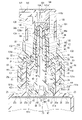
本発明の一実施形態に係るポンプ容器10を、図1乃至図6を用いて説明する。図1は、ポンプ容器10を示す断面図である。図2乃至図4は、ポンプ容器10に用いられるポンプ50、及びその近傍を示す断面図である。図2は、ポンプ50に用いられる上部ピストン80が上死点P1にある状態を示している。図3は、上部ピストン80が、上死点P1及び下死点P2の間の中途部にある状態を示している。図4は、上部ピストン80が下死点P2にある状態を示している。図5は、上死点P3にある、ポンプ容器10に用いられる容器20の下部ピストン40、及びその近傍を示す断面図である。 The pump container 10 according to the embodiment of the present invention will be described with reference to FIGS. 1 to 6. FIG. 1 is a cross-sectional view showing a pump container 10. 2 to 4 are cross-sectional views showing the pump 50 used for the pump container 10 and its vicinity. FIG. 2 shows a state in which the upper piston 80 used for the pump 50 is at top dead center P1. FIG. 3 shows a state in which the upper piston 80 is in the middle part between the top dead center P1 and the bottom dead center P2. FIG. 4 shows a state in which the upper piston 80 is at the bottom dead center P2. FIG. 5 is a cross-sectional view showing the lower piston 40 of the container 20 used for the pump container 10 and its vicinity at the top dead center P3.

図1に示すように、ポンプ容器10は、液状物Lを貯留可能な容器20、容器20に取り付けられるポンプ50、及びポンプ50に着脱可能に取り付けられるオーバーキャップ150を有している。ポンプ50の後述するノズル140の押し込み方向を下方として、ポンプ容器10に上下方向を設定する。 As shown in FIG. 1, the pump container 10 has a container 20 capable of storing a liquid L, a pump 50 attached to the container 20, and an overcap 150 detachably attached to the pump 50. The pump container 10 is set in the vertical direction with the pushing direction of the nozzle 140, which will be described later, of the pump 50 as the downward direction.

容器20は、筒状に形成された容器本体21、容器本体21の下端開口に取り付けられ、この下端開口を閉塞するボトムキャップ30、及び、容器本体21内に収容された下部ピストン40を有している。
容器本体21は、胴部22、胴部22の上端に一体に形成された肩部23、及び肩部23に一体に形成された首部24を有している。胴部22は、軸線が上下方向に平行となる例えば円筒状に形成されている。胴部22の内周面22aの下端部には、環状の凹部22bが形成されている。
The container 20 has a container body 21 formed in a cylindrical shape, a bottom cap 30 attached to the lower end opening of the container body 21 and closing the lower end opening, and a lower piston 40 housed in the container body 21. ing.
The container body 21 has a body portion 22, a shoulder portion 23 integrally formed at the upper end of the body portion 22, and a neck portion 24 integrally formed with the shoulder portion 23. The body portion 22 is formed in, for example, a cylindrical shape whose axes are parallel in the vertical direction. An annular recess 22b is formed at the lower end of the inner peripheral surface 22a of the body portion 22.

図2に示すように、肩部23は、胴部22の径方向内側に向かって延出しており、環状に形成されている。肩部23の下面25は、下部ピストン40の上面45が面接触可能な面に形成されている。具体的には、下面25の内縁部25aは、胴部22の軸線に直交する平面に形成されている。下面25の、内縁部25aより外側の部分となる外縁部25bは、下方に進むにつれて、胴部22の軸線からの径が漸次拡径する円錐面に形成されている。 As shown in FIG. 2, the shoulder portion 23 extends inward in the radial direction of the body portion 22 and is formed in an annular shape. The lower surface 25 of the shoulder portion 23 is formed on a surface on which the upper surface 45 of the lower piston 40 can be surface-contacted. Specifically, the inner edge portion 25a of the lower surface 25 is formed on a plane orthogonal to the axis of the body portion 22. The outer edge portion 25b of the lower surface 25, which is a portion outside the inner edge portion 25a, is formed on a conical surface whose diameter from the axis of the body portion 22 gradually increases as it advances downward.

首部24は、胴部22よりも外径が小さい円筒状に形成されている。首部24は、胴部22と同心状に配置されている。首部24の内周面26の下端部には、径方向内側に突出する環状の突出部27が形成されている。突出部27は、内側に、ポンプ50の後述するシリンダ60が嵌合する。突出部27は、嵌合により、シリンダ60との間を密閉する。首部24の外周面28には、雄ねじ28aが形成されている。 The neck portion 24 is formed in a cylindrical shape having an outer diameter smaller than that of the body portion 22. The neck portion 24 is arranged concentrically with the body portion 22. An annular projecting portion 27 projecting inward in the radial direction is formed at the lower end portion of the inner peripheral surface 26 of the neck portion 24. A cylinder 60, which will be described later, of the pump 50 is fitted inside the protrusion 27. The protrusion 27 is sealed between the protrusion 27 and the cylinder 60 by fitting. A male screw 28a is formed on the outer peripheral surface 28 of the neck portion 24.

ボトムキャップ30は、図1に示すように、有底筒状のボトムキャップ本体31、及びボトムキャップ本体31の底面32に形成された突出部33を有している。ボトムキャップ本体31の外周面には、胴部22の凹部22bに嵌合する環状の凸部31aが形成されている。ボトムキャップ本体31の外周面の下端には、容器本体21の下端に当接するフランジ34が形成されている。突出部33は、例えば筒状に形成されている。突出部33は、ボトムキャップ本体31の上端よりも上方に突出している。 As shown in FIG. 1, the bottom cap 30 has a bottom cap main body 31 having a bottomed tubular shape and a protruding portion 33 formed on the bottom surface 32 of the bottom cap main body 31. An annular convex portion 31a that fits into the concave portion 22b of the body portion 22 is formed on the outer peripheral surface of the bottom cap main body 31. At the lower end of the outer peripheral surface of the bottom cap main body 31, a flange 34 that abuts on the lower end of the container main body 21 is formed. The protrusion 33 is formed in a cylindrical shape, for example. The protruding portion 33 projects upward from the upper end of the bottom cap main body 31.

下部ピストン40は、胴部22の内周面22aに密着した状態で、胴部22内を上下に移動可能に構成されている。下部ピストン40は、具体的には、下部ピストン基部41、及び、下部ピストン基部41に一体に形成された下部ピストン外周部42を有している。下部ピストン基部41は、円筒状に形成されたピストン胴部43、及びピストン胴部43の上端に形成された上壁部44を有している。ピストン胴部43は、胴部22の内径よりも小さい外径を有している。 The lower piston 40 is configured to be movable up and down in the body portion 22 in a state of being in close contact with the inner peripheral surface 22a of the body portion 22. Specifically, the lower piston 40 has a lower piston base 41 and a lower piston outer peripheral portion 42 integrally formed with the lower piston base 41. The lower piston base 41 has a cylindrical piston body 43 and an upper wall 44 formed at the upper end of the piston body 43. The piston body 43 has an outer diameter smaller than the inner diameter of the body 22.

上壁部44の上面45は、容器本体21の肩部23の下面25、及びポンプ50の後述するシリンダ60の下面65に面接触可能な面に形成されている。上面45は、具体的には、内側部46、及び内側部46より径方向外側の部分となる環状の外側部47を有している。
上壁部44の下面48には、下方に突出する突出部49が形成されている。突出部49は、下部ピストン基部41と同心状に配置されている。突出部49がボトムキャップの突出部33に当接する位置が、下部ピストン40の下死点P4となる。
The upper surface 45 of the upper wall portion 44 is formed on a surface that can be surface-contacted with the lower surface 25 of the shoulder portion 23 of the container body 21 and the lower surface 65 of the cylinder 60 described later of the pump 50. Specifically, the upper surface 45 has an inner portion 46 and an annular outer portion 47 which is a portion radially outer from the inner portion 46.
A protruding portion 49 projecting downward is formed on the lower surface 48 of the upper wall portion 44. The protrusion 49 is arranged concentrically with the lower piston base 41. The position where the protruding portion 49 abuts on the protruding portion 33 of the bottom cap is the bottom dead center P4 of the lower piston 40.

内側部46は、上面45のうち、上下方向に下面25の内縁部25aに対向する部分である。内側部46は、ピストン胴部43の軸線に直交する平面に形成されている。下部ピストン基部41が胴部22内に同心状に配置されることにより、内側部46が内縁部25aに面接触可能となる。
外側部47は、上下方向に、下面25の外縁部25bの一部と対向する部分である。外側部47は、ピストン胴部43の軸線を中心として下方に進むにつれて漸次拡径する円錐面に形成されており、外縁部25bに面接触可能である。
The inner portion 46 is a portion of the upper surface 45 facing the inner edge portion 25a of the lower surface 25 in the vertical direction. The inner portion 46 is formed in a plane orthogonal to the axis of the piston body portion 43. By arranging the lower piston base 41 concentrically in the body 22, the inner portion 46 can come into surface contact with the inner edge 25a.
The outer portion 47 is a portion that faces a part of the outer edge portion 25b of the lower surface 25 in the vertical direction. The outer portion 47 is formed on a conical surface whose diameter gradually increases as it advances downward with the axis of the piston body 43 as the center, and is in surface contact with the outer edge portion 25b.

下部ピストン外周部42は、筒状に形成されている。下部ピストン外周部42は、下部ピストン基部41を内側に配置している。下部ピストン外周部42は、下部ピストン基部41と同心状に配置されている。下部ピストン外周部42の内周面の上下方向の中途部は、ピストン胴部43の下端部に一体に形成されている。下部ピストン外周部42の外周面の上端部は、上方に進むにつれて拡径する円錐面に形成されている。下部ピストン外周部42、及び下部ピストン基部41の間には隙間S1が形成されている。 The lower piston outer peripheral portion 42 is formed in a cylindrical shape. The lower piston outer peripheral portion 42 has a lower piston base 41 arranged inside. The lower piston outer peripheral portion 42 is arranged concentrically with the lower piston base 41. The vertical middle portion of the inner peripheral surface of the lower piston outer peripheral portion 42 is integrally formed with the lower end portion of the piston body portion 43. The upper end of the outer peripheral surface of the lower piston outer peripheral portion 42 is formed in a conical surface whose diameter increases as it advances upward. A gap S1 is formed between the lower piston outer peripheral portion 42 and the lower piston base 41.

下部ピストン外周部42の外周面の上端の外径は、胴部22の内径よりも大きい。この上端は、上面45よりも下方に位置している。下部ピストン40を胴部22内に設置することにより下部ピストン外周部42が隙間S1によりたわみ、内周面22aに密着する。下部ピストン外周部42の外周面の下端部は、下方に進むにつれて拡径する円錐面に形成されている。下部ピストン外周部42の外周面の下端の外径は、胴部22の内径よりも大きい。下部ピストン40を胴部22内に設置すると、下部ピストン外周部42がたわむことにより、内周面22aに密着する。 The outer diameter of the upper end of the outer peripheral surface of the lower piston outer peripheral portion 42 is larger than the inner diameter of the body portion 22. This upper end is located below the upper surface 45. By installing the lower piston 40 in the body portion 22, the lower peripheral portion 42 bends due to the gap S1 and comes into close contact with the inner peripheral surface 22a. The lower end of the outer peripheral surface of the lower piston outer peripheral portion 42 is formed in a conical surface whose diameter increases as it goes downward. The outer diameter of the lower end of the outer peripheral surface of the lower piston outer peripheral portion 42 is larger than the inner diameter of the body portion 22. When the lower piston 40 is installed in the body portion 22, the lower peripheral portion 42 bends and comes into close contact with the inner peripheral surface 22a.

ポンプ50は、首部24内に配置された有底筒状のシリンダ60、シリンダ60の底壁部に設けられた第1のバルブ70、シリンダ60内に上下方向に移動可能に収容された筒状の上部ピストン80を有している。ポンプ50は、さらに、上部ピストン80を支持する筒状のピストンホルダ90、ピストンホルダ90内に配置されたロッド100、及び上部ピストン80を上方に付勢する付勢部材110を有している。ポンプ50は、さらに、ピストンホルダ90の上端部に設けられた第2のバルブ120、首部24を内側に配置する筒状のベースキャップ130、及び、ノズル140を有している。 The pump 50 has a bottomed cylindrical cylinder 60 arranged in the neck portion 24, a first valve 70 provided in the bottom wall portion of the cylinder 60, and a tubular shape accommodated in the cylinder 60 so as to be movable in the vertical direction. Has an upper piston 80. The pump 50 further has a cylindrical piston holder 90 that supports the upper piston 80, a rod 100 that is arranged in the piston holder 90, and an urging member 110 that urges the upper piston 80 upward. The pump 50 further has a second valve 120 provided at the upper end of the piston holder 90, a tubular base cap 130 for arranging the neck 24 inside, and a nozzle 140.

シリンダ60は、図2に示すように、円筒状に形成されたシリンダ本体61、及びシリンダ本体61の下端に設けられた底壁部62を有している。
シリンダ本体61は、首部24の突出部27より上方部分の内径よりわずかに小さい外径を有する円筒状に形成されている。シリンダ本体61は、首部24と同心状に配置されている。シリンダ本体61の上端には、フランジ63が形成されている。フランジ63は、首部24の上端より大径に形成されている。フランジ63及び首部24の上端の間には、パッキン64が設けられている。パッキン64は、環状に形成されている。
As shown in FIG. 2, the cylinder 60 has a cylinder body 61 formed in a cylindrical shape and a bottom wall portion 62 provided at the lower end of the cylinder body 61.
The cylinder body 61 is formed in a cylindrical shape having an outer diameter slightly smaller than the inner diameter of the portion above the protruding portion 27 of the neck portion 24. The cylinder body 61 is arranged concentrically with the neck portion 24. A flange 63 is formed at the upper end of the cylinder body 61. The flange 63 is formed to have a larger diameter than the upper end of the neck portion 24. A packing 64 is provided between the flange 63 and the upper ends of the neck portion 24. The packing 64 is formed in an annular shape.

シリンダ本体61の下端部は、円錐部61a、及び円錐部61aの下端に形成された円筒部61bを有している。円錐部61aの内周面及び外周面は、下方に向かうにつれて漸次縮径する円錐面に形成されている。円筒部61bの内径は、円錐部61aの内周面の下端と同径である。円筒部61bの外径は、円錐部61aの外周面の下端と同径である。 The lower end of the cylinder body 61 has a conical portion 61a and a cylindrical portion 61b formed at the lower end of the conical portion 61a. The inner peripheral surface and the outer peripheral surface of the conical portion 61a are formed into a conical surface whose diameter gradually decreases toward the bottom. The inner diameter of the cylindrical portion 61b is the same as the lower end of the inner peripheral surface of the conical portion 61a. The outer diameter of the cylindrical portion 61b is the same as the lower diameter of the outer peripheral surface of the conical portion 61a.

底壁部62は、首部24の突出部27の内側に嵌合している。底壁部62の厚みは、シリンダ本体61の厚みよりも厚い。また、底壁部62の厚みは、突出部27の高さよりも大きい。
底壁部62は、突出部27の内径と同径、または、わずかに小さい外径を有している。底壁部62の下面65は、肩部23の下面25の内縁部25aと面一となる平面に形成されている。下面65は、具体的には、シリンダ本体61の軸線に直交する平面に形成されている。シリンダ60が、首部24に同心状に配置され、フランジ63がパッキン64上に配置されることにより、下面65が、肩部23の下面25の内縁部25aと面一になる。
The bottom wall portion 62 is fitted inside the protruding portion 27 of the neck portion 24. The thickness of the bottom wall portion 62 is thicker than the thickness of the cylinder body 61. Further, the thickness of the bottom wall portion 62 is larger than the height of the protruding portion 27.
The bottom wall portion 62 has an outer diameter equal to or slightly smaller than the inner diameter of the protruding portion 27. The lower surface 65 of the bottom wall portion 62 is formed on a flat surface that is flush with the inner edge portion 25a of the lower surface portion 25 of the shoulder portion 23. Specifically, the lower surface 65 is formed on a plane orthogonal to the axis of the cylinder body 61. The cylinder 60 is concentrically arranged on the neck 24 and the flange 63 is arranged on the packing 64 so that the lower surface 65 is flush with the inner edge 25a of the lower surface 25 of the shoulder 23.

なお、下面65は、本実施形態では、第1のバルブ70の弁座を構成する孔66を避けた位置に、シリンダ60を射出成形する際のひけの発生を防止する為の凹部67が形成されている。底壁部62の上面68は、シリンダ本体61の軸線に直交する平面に形成されている。 In the present embodiment, the lower surface 65 is formed with a recess 67 for preventing the occurrence of sink marks when the cylinder 60 is injection-molded at a position avoiding the hole 66 constituting the valve seat of the first valve 70. Has been done. The upper surface 68 of the bottom wall portion 62 is formed in a plane orthogonal to the axis of the cylinder body 61.

第1のバルブ70は、容器20からシリンダ60内への液状物Lの移動を許容し、シリンダ60から容器20への液状物Lの移動を規制する逆止弁である。第1のバルブ70は、例えばボール弁である。第1のバルブ70は、弁座を構成する孔66の内周面71、及び球体に形成された第1の弁体72を有している。孔66は、底壁部62と同心状に形成されている。内周面71は、下方に向かうにつれて漸次縮径する円錐面に形成されている。第1の弁体72は、内周面71に密着することにより、孔66を密閉可能に構成されている。 The first valve 70 is a check valve that allows the movement of the liquid material L from the container 20 into the cylinder 60 and restricts the movement of the liquid material L from the cylinder 60 to the container 20. The first valve 70 is, for example, a ball valve. The first valve 70 has an inner peripheral surface 71 of a hole 66 constituting a valve seat, and a first valve body 72 formed in a sphere. The hole 66 is formed concentrically with the bottom wall portion 62. The inner peripheral surface 71 is formed as a conical surface whose diameter gradually decreases toward the bottom. The first valve body 72 is configured to be able to seal the hole 66 by being in close contact with the inner peripheral surface 71.

上部ピストン80は、シリンダ本体61と同心状に配置されている。上部ピストン80は、シリンダ本体61の内周面に密着する筒状に形成されている。上部ピストン80は、具体的には、円筒状に形成された上部ピストン基部81、及び上部ピストン基部81を内側に配置する筒状に形成され、シリンダ本体61の内周面に密着する上部ピストン外周部82を有している。上部ピストン基部81は、上部ピストン外周部82の上端より上方に突出している。 The upper piston 80 is arranged concentrically with the cylinder body 61. The upper piston 80 is formed in a cylindrical shape that is in close contact with the inner peripheral surface of the cylinder body 61. Specifically, the upper piston 80 is formed in a cylindrical shape in which the upper piston base 81 formed in a cylindrical shape and the upper piston base 81 are arranged inside, and is in close contact with the inner peripheral surface of the cylinder body 61. It has a part 82. The upper piston base 81 projects upward from the upper end of the upper piston outer peripheral portion 82.

上部ピストン外周部82の内周面の上下方向中途部は、上部ピストン基部81の下端部に一体に形成されている。上部ピストン外周部82は、上部ピストン基部81との間に隙間S2を有している。
上部ピストン外周部82の上下方向中途部より上方の部分の内周面及び外周面は、上方に向かうにつれて漸次拡径する円錐面に形成されている。上部ピストン外周部82の外周面の上端の外径は、シリンダ本体61の内径より大きい。上部ピストン80をシリンダ本体61内に設置することにより、上部ピストン外周部82の上端部は、たわんでシリンダ本体61の内周面に密着する。
The vertical middle portion of the inner peripheral surface of the upper piston outer peripheral portion 82 is integrally formed with the lower end portion of the upper piston base 81. The upper piston outer peripheral portion 82 has a gap S2 between the upper piston base portion 81 and the upper piston base portion 81.
The inner peripheral surface and the outer peripheral surface of the portion of the outer peripheral portion 82 of the upper piston above the middle portion in the vertical direction are formed into a conical surface whose diameter gradually increases toward the upper side. The outer diameter of the upper end of the outer peripheral surface of the upper piston outer peripheral portion 82 is larger than the inner diameter of the cylinder body 61. By installing the upper piston 80 in the cylinder body 61, the upper end portion of the upper piston outer peripheral portion 82 bends and comes into close contact with the inner peripheral surface of the cylinder body 61.

上部ピストン外周部82の上下方向中途部より下方の部分の内周面及び外周面は、下方に向かうにつれて漸次拡径する円錐面に形成されている。上部ピストン外周部82の外周面の下端の外径は、シリンダ本体61の内径より大きい。上部ピストン80がシリンダ本体61内に設置されることにより、上部ピストン外周部82の下端部は、たわんでシリンダ本体61の内周面に密着する。 The inner peripheral surface and the outer peripheral surface of the portion of the outer peripheral portion 82 of the upper piston below the middle portion in the vertical direction are formed into a conical surface whose diameter gradually increases toward the lower side. The outer diameter of the lower end of the outer peripheral surface of the upper piston outer peripheral portion 82 is larger than the inner diameter of the cylinder body 61. By installing the upper piston 80 in the cylinder body 61, the lower end portion of the upper piston outer peripheral portion 82 bends and comes into close contact with the inner peripheral surface of the cylinder body 61.

ピストンホルダ90は、円筒状に形成されたホルダ本体91、ホルダ本体91に形成され、上部ピストン80が固定される固定部92、及びホルダ本体91の下端に形成され、ピストンホルダ90の移動を規制するロッド規制部93を有している。
ホルダ本体91は、上部ピストン80と同心状に配置されている。ホルダ本体91は、複数の外径を有する円筒状に形成されている。ホルダ本体91は、具体的には、ホルダ中径部94、ホルダ大径部95、及びホルダ小径部96を有している。ホルダ大径部95は、ホルダ中径部94の上端に形成されている。ホルダ小径部96は、ホルダ大径部95の上端に形成されている。ホルダ小径部96の外周面には、環状のロッド突出部97が形成されている。ホルダ小径部96の内周面96aの上端部96bは、円錐面に形成されている。
The piston holder 90 is formed in a cylindrical holder body 91, a holder body 91, a fixing portion 92 to which the upper piston 80 is fixed, and a lower end of the holder body 91, and restricts the movement of the piston holder 90. It has a rod regulation unit 93 to be used.
The holder body 91 is arranged concentrically with the upper piston 80. The holder body 91 is formed in a cylindrical shape having a plurality of outer diameters. Specifically, the holder main body 91 has a holder medium diameter portion 94, a holder large diameter portion 95, and a holder small diameter portion 96. The holder large diameter portion 95 is formed at the upper end of the holder medium diameter portion 94. The holder small diameter portion 96 is formed at the upper end of the holder large diameter portion 95. An annular rod protrusion 97 is formed on the outer peripheral surface of the holder small diameter portion 96. The upper end portion 96b of the inner peripheral surface 96a of the holder small diameter portion 96 is formed in a conical surface.

ホルダ本体91の内周面は、複数の内径を有している。具体的には、ホルダ中径部94の下端からホルダ大径部95の上端よりわずかに低い位置までの範囲の内径に対して、それより上方の内径が小径である。この為、ホルダ本体91の内周面は、この異なる内径を有する2つの部分の間に、端面98を有している。端面98は、付勢部材110の上端を支持する。換言すると、ホルダ本体91の内周面は、付勢部材110の上端を支持可能とする為に異なる内径を有している。 The inner peripheral surface of the holder body 91 has a plurality of inner diameters. Specifically, the inner diameter above the inner diameter in the range from the lower end of the middle diameter portion 94 of the holder to a position slightly lower than the upper end of the large diameter portion 95 of the holder is a small diameter. Therefore, the inner peripheral surface of the holder body 91 has an end surface 98 between the two portions having different inner diameters. The end face 98 supports the upper end of the urging member 110. In other words, the inner peripheral surface of the holder body 91 has a different inner diameter so that the upper end of the urging member 110 can be supported.

固定部92は、円筒状に形成されており、内側にホルダ中径部94の一部を配置している。固定部92は、上端がホルダ中径部94の外周面の上端に一体に形成されている。固定部92は、ホルダ中径部94との間に、上部ピストン基部81を固定する。具体的に説明すると、上部ピストン80が固定部92に固定されていない状態では、固定部92は、ホルダ中径部94との間に環状の隙間を有する。上部ピストン基部81は、この隙間に嵌合することにより、固定部92に固定される。
ロッド規制部93は、ホルダ本体91の下面に形成された突出部である。ロッド規制部93は、複数形成されている。ロッド規制部93間は、液状物Lが流動可能な隙間に形成されている。
The fixing portion 92 is formed in a cylindrical shape, and a part of the holder medium diameter portion 94 is arranged inside. The upper end of the fixing portion 92 is integrally formed with the upper end of the outer peripheral surface of the holder middle diameter portion 94. The fixing portion 92 fixes the upper piston base 81 to the holder middle diameter portion 94. Specifically, in a state where the upper piston 80 is not fixed to the fixed portion 92, the fixed portion 92 has an annular gap between the fixed portion 92 and the holder medium diameter portion 94. The upper piston base 81 is fixed to the fixing portion 92 by fitting into this gap.
The rod regulating portion 93 is a protruding portion formed on the lower surface of the holder main body 91. A plurality of rod regulating portions 93 are formed. The space between the rod regulating portions 93 is formed in a gap through which the liquid material L can flow.

ロッド100は、シリンダ60の底壁部62に支持されるロッド基部101、及びロッド基部101と一体に形成されたロッド部102を有している。
ロッド基部101は、シリンダ60の底壁部62に設置される。ロッド基部101は、周面が例えば円錐面に形成された筒状に形成されている。ロッド基部101は、シリンダ本体61と同心状に配置されている。ロッド基部101の外周面の下端部には、径方向外側に突出する環状の突出部103が形成されている。突出部103の外径は、シリンダ本体61の円筒部61bの内径よりわずかに小さい。ロッド基部101の内側は、底壁部62の孔66と対向する。
The rod 100 has a rod base 101 supported by the bottom wall portion 62 of the cylinder 60, and a rod portion 102 integrally formed with the rod base 101.
The rod base 101 is installed on the bottom wall portion 62 of the cylinder 60. The rod base 101 is formed in a cylindrical shape having a peripheral surface formed into, for example, a conical surface. The rod base 101 is arranged concentrically with the cylinder body 61. An annular protrusion 103 that protrudes outward in the radial direction is formed at the lower end of the outer peripheral surface of the rod base 101. The outer diameter of the protruding portion 103 is slightly smaller than the inner diameter of the cylindrical portion 61b of the cylinder body 61. The inside of the rod base 101 faces the hole 66 of the bottom wall portion 62.

ロッド基部101の内径は、第1のバルブ70の第1の弁体72の直径より大きい。この為、第1の弁体72は、ロッド基部101の内側に移動可能である。ロッド基部101の内周面は、第1の弁体72が孔66から大きくずれることを防止するガイドとして機能する。
ロッド基部101の内径は、本実施形態では、孔66の最大外径よりわずかに小さい。ロッド基部101は、径方向に貫通する溝101bが形成されている。溝101bは、例えば複数形成されている。これら複数の溝101bは、周方向に並んでいる。溝101bは、液状物Lが流動可能に形成されている。
The inner diameter of the rod base 101 is larger than the diameter of the first valve body 72 of the first valve 70. Therefore, the first valve body 72 can move inside the rod base 101. The inner peripheral surface of the rod base 101 functions as a guide for preventing the first valve body 72 from being significantly displaced from the hole 66.
The inner diameter of the rod base 101 is slightly smaller than the maximum outer diameter of the hole 66 in this embodiment. The rod base 101 is formed with a groove 101b penetrating in the radial direction. A plurality of grooves 101b are formed, for example. These plurality of grooves 101b are arranged in the circumferential direction. The groove 101b is formed so that the liquid material L can flow.

図4に示すように、ロッド基部101は、上部ピストン外周部82内に位置可能な外径を有している。ロッド基部101は、ピストンホルダ90のロッド規制部93が当接することにより、ピストンホルダ90の下方への移動を規制する。ロッド規制部93がロッド基部101の上面に当接する位置が、上部ピストン80の下死点P2となる。 As shown in FIG. 4, the rod base 101 has an outer diameter that can be positioned in the outer peripheral portion 82 of the upper piston. The rod base 101 restricts the downward movement of the piston holder 90 by abutting the rod regulating portion 93 of the piston holder 90. The position where the rod regulating portion 93 abuts on the upper surface of the rod base 101 is the bottom dead center P2 of the upper piston 80.

ロッド部102は、図2に示すように、ロッド基部101の上面に一体に形成されている。ロッド部102は、ロッド基部101と同心状に配置されている。ロッド部102の一部は、ホルダ本体91内に配置されている。ロッド部102は、ロッド大径部104、ロッド小径部105、及び、第2のバルブ120の一部を構成する挟持部106を有している。 As shown in FIG. 2, the rod portion 102 is integrally formed on the upper surface of the rod base portion 101. The rod portion 102 is arranged concentrically with the rod base portion 101. A part of the rod portion 102 is arranged in the holder main body 91. The rod portion 102 has a rod large diameter portion 104, a rod small diameter portion 105, and a holding portion 106 that forms a part of the second valve 120.

ロッド大径部104は、ロッド基部101の上面からシリンダ60の上端よりわずかに上方の位置までの部分である。ロッド大径部104は、ロッド基部101に連通する円筒状に形成されている。
ロッド小径部105は、ロッド大径部104より上方の部分である。ロッド小径部105は、ロッド大径部104よりも小径に形成されている。ロッド小径部105は、上部ピストン80が上死点P1にある状態での、ピストンホルダ90の上端よりわずかに下方の位置まで延びている。
The rod large diameter portion 104 is a portion from the upper surface of the rod base 101 to a position slightly above the upper end of the cylinder 60. The rod large diameter portion 104 is formed in a cylindrical shape that communicates with the rod base 101.
The rod small diameter portion 105 is a portion above the rod large diameter portion 104. The rod small diameter portion 105 is formed to have a smaller diameter than the rod large diameter portion 104. The rod small diameter portion 105 extends to a position slightly below the upper end of the piston holder 90 in a state where the upper piston 80 is at top dead center P1.

挟持部106は、ロッド小径部105の上端に形成されている。挟持部106は、ロッド小径部105の径方向外側に突出している。本実施形態では、挟持部106の下端部の周面は、円錐面に形成されている。この円錐面は、具体的には、ロッド小径部105の軸線を中心として、上方に進むにつれて漸次拡径する円錐面である。挟持部106の上端部の周面は、半球状に形成されている。 The sandwiching portion 106 is formed at the upper end of the rod small diameter portion 105. The sandwiching portion 106 projects radially outward of the rod small diameter portion 105. In the present embodiment, the peripheral surface of the lower end portion of the sandwiching portion 106 is formed as a conical surface. Specifically, this conical surface is a conical surface whose diameter gradually increases as it advances upward with the axis of the rod small diameter portion 105 as the center. The peripheral surface of the upper end portion of the sandwiching portion 106 is formed in a hemispherical shape.

付勢部材110は、本実施形態では、ピストンホルダ90を上方に付勢することにより、上部ピストン80を上方に付勢する。付勢部材110は、例えばコイルばねである。付勢部材110の一部は、ピストンホルダ90内に配置されている。付勢部材110は、内側にロッド100を配置している。付勢部材110の上端は、ピストンホルダ90の端面98に当接している。付勢部材110の下端は、ロッド基部101の上面に当接している。付勢部材110は、縮んで弾性エネルギを蓄えた状態で、設置されている。付勢部材110は、ノズル140が下方に移動していない状態では、付勢力により、上部ピストン80を上死点P1に固定する。 In the present embodiment, the urging member 110 urges the upper piston 80 upward by urging the piston holder 90 upward. The urging member 110 is, for example, a coil spring. A part of the urging member 110 is arranged in the piston holder 90. The urging member 110 has a rod 100 arranged inside. The upper end of the urging member 110 is in contact with the end surface 98 of the piston holder 90. The lower end of the urging member 110 is in contact with the upper surface of the rod base 101. The urging member 110 is installed in a state of being contracted and storing elastic energy. The urging member 110 fixes the upper piston 80 to the top dead center P1 by the urging force in a state where the nozzle 140 has not moved downward.

第2のバルブ120は、内周面96aの上端部96b、及び第2の弁体121、及び挟持部106を有している。円錐面に形成された上端部96bは、弁座である。
第2の弁体121は、筒状に形成されている。第2の弁体121は、ロッド小径部105及び挟持部106を内側に配置する。第2の弁体121は、バルブ小径部124、バルブ円錐部125、及びバルブ大径部126を有している。
The second valve 120 has an upper end portion 96b of the inner peripheral surface 96a, a second valve body 121, and a sandwiching portion 106. The upper end 96b formed on the conical surface is a valve seat.
The second valve body 121 is formed in a cylindrical shape. The second valve body 121 has a rod small diameter portion 105 and a holding portion 106 arranged inside. The second valve body 121 has a valve small diameter portion 124, a valve conical portion 125, and a valve large diameter portion 126.

バルブ小径部124は、円筒状に形成されている。バルブ小径部124は、ピストンホルダ90のホルダ小径部96内を上下方向に移動可能に形成されている。バルブ小径部124は、具体的には、その外径が、ホルダ小径部96の内径よりも小さい。
バルブ小径部124は、内側にロッド100のロッド小径部105を保持する。具体的には、バルブ小径部124は、ロッド100に対して上下方向に所定の力で押圧されると移動可能に、バルブ小径部124を保持する。換言すると、第2の弁体121を下方または上方に押圧する力が所定の力となるまでは、バルブ小径部124は、ロッド小径部105を摩擦力により保持する。
The valve small diameter portion 124 is formed in a cylindrical shape. The valve small diameter portion 124 is formed so as to be movable in the vertical direction in the holder small diameter portion 96 of the piston holder 90. Specifically, the outer diameter of the valve small diameter portion 124 is smaller than the inner diameter of the holder small diameter portion 96.
The valve small diameter portion 124 holds the rod small diameter portion 105 of the rod 100 inside. Specifically, the valve small diameter portion 124 holds the valve small diameter portion 124 so as to be movable when pressed with a predetermined force in the vertical direction with respect to the rod 100. In other words, the valve small diameter portion 124 holds the rod small diameter portion 105 by a frictional force until the force for pressing the second valve body 121 downward or upward becomes a predetermined force.

バルブ小径部124は、具体的には、内径がロッド100のロッド小径部105の外径よりもわずかに大きい。そして、バルブ小径部124の内周面には、ロッド小径部105が嵌合するバルブ突出部127が形成されている。バルブ突出部127は、バルブ小径部124の内周面の周方向に環状に形成されている。バルブ突出部127は、複数、具体的には、2つ形成されている。バルブ小径部124は、複数のバルブ突出部127及びロッド小径部105の間に生じる摩擦力により、ロッド小径部105を保持する。
さらに、バルブ小径部124及びロッド小径部105の間には、シールが設けられている。本実施形態では、バルブ突出部127が、シールとしても機能している。バルブ突出部127は、ロッド小径部105との間を密閉可能に形成されている。具体的には、バルブ突出部127の内径は、ロッド小径部105の外径よりわずかに小さい。
Specifically, the valve small diameter portion 124 has an inner diameter slightly larger than the outer diameter of the rod small diameter portion 105 of the rod 100. A valve protrusion 127 into which the rod small diameter portion 105 is fitted is formed on the inner peripheral surface of the valve small diameter portion 124. The valve protrusion 127 is formed in an annular shape in the circumferential direction of the inner peripheral surface of the valve small diameter portion 124. A plurality of valve protrusions 127, specifically, two are formed. The valve small diameter portion 124 holds the rod small diameter portion 105 by the frictional force generated between the plurality of valve protrusions 127 and the rod small diameter portion 105.
Further, a seal is provided between the valve small diameter portion 124 and the rod small diameter portion 105. In this embodiment, the valve protrusion 127 also functions as a seal. The valve protrusion 127 is formed so as to be hermetically sealed between the rod protrusion and the rod small diameter portion 105. Specifically, the inner diameter of the valve protrusion 127 is slightly smaller than the outer diameter of the rod small diameter portion 105.

バルブ円錐部125は、バルブ小径部124の上端に一体に形成されている。バルブ円錐部125は、内周面125a、及び外周面125bを有している。バルブ円錐部125は、上部ピストン80が上死点P1にある状態では、付勢部材110の付勢力により、挟持部106及びホルダ小径部96の開口の間に挟持される。さらに、バルブ円錐部125は、この挟持により、ホルダ小径部96の開口との間を密閉可能に形成されている。 The valve conical portion 125 is integrally formed at the upper end of the valve small diameter portion 124. The valve conical portion 125 has an inner peripheral surface 125a and an outer peripheral surface 125b. The valve conical portion 125 is sandwiched between the openings of the sandwiching portion 106 and the holder small diameter portion 96 by the urging force of the urging member 110 when the upper piston 80 is at the top dead center P1. Further, the valve conical portion 125 is formed so as to be hermetically sealed between the valve conical portion 125 and the opening of the holder small diameter portion 96 by this sandwiching.

バルブ円錐部125の内周面125a及び外周面125bは、上方に進むにつれて漸次拡径する円錐面に形成されている。外周面125bは、内周面96aの上端部96bに面接触することにより、上端部96bとの間を密閉可能な円錐面に形成されている。 The inner peripheral surface 125a and the outer peripheral surface 125b of the valve conical portion 125 are formed on a conical surface whose diameter gradually increases as the valve cone portion 125 moves upward. The outer peripheral surface 125b is formed into a conical surface that can be sealed between the outer peripheral surface 125b and the upper end portion 96b by making surface contact with the upper end portion 96b of the inner peripheral surface 96a.

バルブ円錐部125の上端の外径は、例えば、ホルダ本体91の内周面の上端と同径である。バルブ円錐部125の外周面125bは、上部ピストン80が上死点P1にある状態では、挟持部106により押圧されることによりホルダ本体91の内周面の上端部96bに密着して外周面125b及上端部96bの間を密閉する。このように、外周面125b及び上端部96bの間が密閉され、かつ、バルブ突出部127及びロッド小径部105の間が密閉されることにより、ホルダ本体91の上端開口が密封される。
内周面125aは、例えば、挟持部106の下端部の円錐面に接触可能な円錐面に形成されている。
バルブ大径部126は、バルブ円錐部125の上端に一体に形成されている。バルブ大径部126の外径は、バルブ円錐部125の上端の外径と同径である。
The outer diameter of the upper end of the valve conical portion 125 is, for example, the same diameter as the upper end of the inner peripheral surface of the holder main body 91. When the upper piston 80 is at the top dead center P1, the outer peripheral surface 125b of the valve conical portion 125 is pressed by the holding portion 106 so as to be in close contact with the upper end portion 96b of the inner peripheral surface of the holder body 91 and the outer peripheral surface 125b. Seal between the upper and lower ends 96b. In this way, the upper end opening of the holder body 91 is sealed by sealing between the outer peripheral surface 125b and the upper end portion 96b and between the valve protrusion 127 and the rod small diameter portion 105.
The inner peripheral surface 125a is formed, for example, as a conical surface that can come into contact with the conical surface at the lower end of the sandwiching portion 106.
The valve large diameter portion 126 is integrally formed at the upper end of the valve cone portion 125. The outer diameter of the valve large diameter portion 126 is the same as the outer diameter of the upper end of the valve conical portion 125.

ベースキャップ130は、首部24に固定される固定部131、及びノズル140の上下方向の移動をガイドするガイド部132を有している。
固定部131は、円筒状に形成されている。固定部131の内周面には、首部24の雄ねじ28aに螺合する雌ねじ131aが形成されている。固定部131の内周面の上端部には、径方向内側に突出する環状のベースキャップ突出部133が形成されている。
ベースキャップ突出部133は、内側にホルダ大径部95を配置可能に形成されている。ベースキャップ突出部133は、具体的には、内径がホルダ大径部95の外径より大きい内径を有している。ベースキャップ突出部133の下面133aは、固定部92が当接可能に形成されている。下面133aに固定部92の上端が当接する位置が、上部ピストン80の上死点P1となる。
The base cap 130 has a fixing portion 131 fixed to the neck portion 24 and a guide portion 132 that guides the vertical movement of the nozzle 140.
The fixing portion 131 is formed in a cylindrical shape. On the inner peripheral surface of the fixing portion 131, a female screw 131a screwed with the male screw 28a of the neck portion 24 is formed. An annular base cap projecting portion 133 projecting inward in the radial direction is formed at the upper end portion of the inner peripheral surface of the fixing portion 131.
The base cap protruding portion 133 is formed so that the holder large diameter portion 95 can be arranged inside. Specifically, the base cap protruding portion 133 has an inner diameter larger than the outer diameter of the holder large diameter portion 95. The lower surface 133a of the base cap projecting portion 133 is formed so that the fixing portion 92 can come into contact with the lower surface 133a. The position where the upper end of the fixing portion 92 abuts on the lower surface 133a is the top dead center P1 of the upper piston 80.

下面133aは、固定部131が首部24の雄ねじ28aに螺合することにより、シリンダ60のフランジ63を、首部24の上端との間に挟持する。また、下面133aには、円筒状の収容部134が形成されている。収容部134は、ベースキャップ突出部133と同心状に形成されている。収容部134は、シリンダ本体61内に嵌合可能に形成されている。本実施形態では、収容部134の外径は、シリンダ本体61の内径よりわずかに大きい。収容部134は、ピストンホルダ90の固定部92の一部を収容可能に形成されている。具体的には、収容部134は、上部ピストン80が上死点P1にある状態において、固定部92の上端部を収容する。収容部134の内周面は、固定部92の外径よりわずかに大きい径を有している。 The lower surface 133a sandwiches the flange 63 of the cylinder 60 between the upper end of the neck 24 and the flange 63 of the cylinder 60 by screwing the fixing portion 131 into the male screw 28a of the neck 24. Further, a cylindrical accommodating portion 134 is formed on the lower surface 133a. The accommodating portion 134 is formed concentrically with the base cap protruding portion 133. The accommodating portion 134 is formed so as to be fitted in the cylinder main body 61. In the present embodiment, the outer diameter of the accommodating portion 134 is slightly larger than the inner diameter of the cylinder body 61. The accommodating portion 134 is formed so as to accommodate a part of the fixing portion 92 of the piston holder 90. Specifically, the accommodating portion 134 accommodates the upper end portion of the fixing portion 92 in a state where the upper piston 80 is at the top dead center P1. The inner peripheral surface of the accommodating portion 134 has a diameter slightly larger than the outer diameter of the fixing portion 92.

ガイド部132は、固定部92の上端に一体に形成されている。ガイド部132は、円筒状に形成されている。ガイド部132は、固定部131と同心状に形成されている。ガイド部132の内周面135は、ノズル140の移動をガイド可能に形成されている。
ノズル140は、ホルダ小径部96を内側に配置し固定する内筒部141、内筒部141を内側に配置し、ガイド部132によりガイドされる外筒部142、及び、ノズル部143を有している。
The guide portion 132 is integrally formed at the upper end of the fixing portion 92. The guide portion 132 is formed in a cylindrical shape. The guide portion 132 is formed concentrically with the fixed portion 131. The inner peripheral surface 135 of the guide portion 132 is formed so as to be able to guide the movement of the nozzle 140.
The nozzle 140 has an inner cylinder portion 141 for arranging and fixing the holder small diameter portion 96 inside, an outer cylinder portion 142 having an inner cylinder portion 141 arranged inside and being guided by a guide portion 132, and a nozzle portion 143. ing.

内筒部141の内径は、ホルダ小径部96の外径と同径、またはわずかに小さい径を有している。内筒部141の下端は、ホルダ小径部96及びホルダ中径部94の間の端面99に当接している。内筒部141は、嵌合により、ホルダ小径部96が固定される。 The inner diameter of the inner cylinder portion 141 has the same diameter as the outer diameter of the holder small diameter portion 96, or a slightly smaller diameter. The lower end of the inner cylinder portion 141 is in contact with the end surface 99 between the holder small diameter portion 96 and the holder medium diameter portion 94. The holder small diameter portion 96 is fixed to the inner cylinder portion 141 by fitting.

内筒部141の上端部には、第2の弁体121の移動を規制する、規制部144が形成されている。規制部144は、内筒部141の内周面141aから内側に突出した突出部である。規制部144は、例えば複数形成されている。ノズル140が下方に移動することにより、内筒部141内を第2の弁体121が上方に相対的に所定距離移動すると、第2の弁体121の上端が規制部144に当接する。この当接により、内筒部141内を第2の弁体121が上方に相対的に移動することが規制される。 A regulation portion 144 that regulates the movement of the second valve body 121 is formed at the upper end portion of the inner cylinder portion 141. The regulating portion 144 is a protruding portion protruding inward from the inner peripheral surface 141a of the inner cylinder portion 141. A plurality of regulatory units 144 are formed, for example. When the second valve body 121 moves upward by a relatively predetermined distance in the inner cylinder portion 141 due to the nozzle 140 moving downward, the upper end of the second valve body 121 comes into contact with the regulating portion 144. This contact restricts the second valve body 121 from relatively upwardly moving within the inner cylinder portion 141.

外筒部142は、ガイド部132の内側に配置される。外筒部142の外径は、ガイド部132の内径よりわずかに小さい径である。
ノズル部143は、内筒部141の上端と連通している。ノズル部143は、例えば、内筒部141の径方向に延びている。
The outer cylinder portion 142 is arranged inside the guide portion 132. The outer diameter of the outer cylinder portion 142 is slightly smaller than the inner diameter of the guide portion 132.
The nozzle portion 143 communicates with the upper end of the inner cylinder portion 141. The nozzle portion 143 extends in the radial direction of the inner cylinder portion 141, for example.

オーバーキャップ150は、図1に示すように、ベースキャップ130及びノズル140を収容可能な、有底筒状に形成されている。オーバーキャップ150は、底部を上方に配置した状態で、着脱可能に取り付けられる。 As shown in FIG. 1, the overcap 150 is formed in a bottomed cylindrical shape capable of accommodating the base cap 130 and the nozzle 140. The overcap 150 is detachably attached with the bottom arranged upward.

次に、ノズル140から液状物Lを吐出する動作を説明する。図2に示すように、ノズル140が下方に押し込まれていない状態では、上部ピストン80は、付勢部材110の付勢力により、上死点P1に配置される。上部ピストン80が上死点P1に維持される状態を、第1の状態とする。第1の状態では、ホルダ本体91の上端開口は、第2の弁体121により密閉される。 Next, the operation of ejecting the liquid substance L from the nozzle 140 will be described. As shown in FIG. 2, in a state where the nozzle 140 is not pushed downward, the upper piston 80 is arranged at top dead center P1 by the urging force of the urging member 110. The state in which the upper piston 80 is maintained at the top dead center P1 is defined as the first state. In the first state, the upper end opening of the holder body 91 is sealed by the second valve body 121.

なお、前回までの使用により、シリンダ60、上部ピストン80、及びホルダ本体91により規定される空間R内には、液状物Lが充填されている。ポンプ容器10を初めて使用する場合など、空間R内に液状物Lが充填されていない場合は、ノズル140を下方に押し込む動作を複数回繰り返す。 Due to the previous use, the space R defined by the cylinder 60, the upper piston 80, and the holder main body 91 is filled with the liquid substance L. When the space R is not filled with the liquid material L, such as when the pump container 10 is used for the first time, the operation of pushing the nozzle 140 downward is repeated a plurality of times.

次に、ノズル140を下方に、付勢部材110の付勢力に抗って押し込むと、ピストンホルダ90及び上部ピストン80が、下方に移動する。ピストンホルダ90が下方に移動することにより、第2の弁体121が、ピストンホルダ90に対して相対的に上方に移動することとなる。 Next, when the nozzle 140 is pushed downward against the urging force of the urging member 110, the piston holder 90 and the upper piston 80 move downward. As the piston holder 90 moves downward, the second valve body 121 moves relatively upward with respect to the piston holder 90.

この為、図3に示すように、内周面96aの上端部96bと第2の弁体121との間に隙間S3が形成される。また、上部ピストン80が下がることにより、空間Rの容積が減少するので、空間R内の液状物Lが、隙間S3、内筒部141、ノズル部143を通って吐出される。
なお、第2の弁体121が規制部144に当接するまでは、第2の弁体121は、バルブ突出部127及びロッド小径部105の間の摩擦力によりロッド100の上部に固定されている。
Therefore, as shown in FIG. 3, a gap S3 is formed between the upper end portion 96b of the inner peripheral surface 96a and the second valve body 121. Further, since the volume of the space R is reduced by lowering the upper piston 80, the liquid material L in the space R is discharged through the gap S3, the inner cylinder portion 141, and the nozzle portion 143.
Until the second valve body 121 comes into contact with the regulation portion 144, the second valve body 121 is fixed to the upper part of the rod 100 by the frictional force between the valve protrusion 127 and the rod small diameter portion 105. ..

ノズル140を所定距離下方に移動すると、図3に示すように規制部144が第2の弁体121に当接する。規制部144が第2の弁体121に当接した状態を第2の状態とする。 When the nozzle 140 is moved downward by a predetermined distance, the regulating portion 144 comes into contact with the second valve body 121 as shown in FIG. The state in which the regulating unit 144 is in contact with the second valve body 121 is defined as the second state.

第2の状態からノズル140を下方に移動する際には、抵抗力として、付勢部材110の付勢力に加えて、第2の弁体121及びロッド100の間の摩擦力が作用する。図4に示すように、第2の状態からノズル140を下方に移動すると、隙間S3を維持しつつ、第2の弁体121が下方に下がる。 When the nozzle 140 is moved downward from the second state, a frictional force between the second valve body 121 and the rod 100 acts as a resistance force in addition to the urging force of the urging member 110. As shown in FIG. 4, when the nozzle 140 is moved downward from the second state, the second valve body 121 is lowered downward while maintaining the gap S3.

ノズル140がさらに下方に移動されると、図4に示すように、ロッド規制部93がロッド基部101の上面101aに当接する。ロッド規制部93が上面101aに当接することにより、ノズル140、ピストンホルダ90、及び上部ピストン80の下方への移動が規制される。ロッド規制部93が上面101aに当接した状態を第3の状態とする。第3の状態は、ノズル140が底付きとなる状態である。 When the nozzle 140 is further moved downward, the rod restricting portion 93 comes into contact with the upper surface 101a of the rod base portion 101, as shown in FIG. When the rod restricting portion 93 abuts on the upper surface 101a, the downward movement of the nozzle 140, the piston holder 90, and the upper piston 80 is restricted. The state in which the rod regulating portion 93 is in contact with the upper surface 101a is defined as the third state. The third state is a state in which the nozzle 140 is bottomed out.

使用者は、第3の状態となるまでノズルを下げると、ノズル140を下方に押圧する動作を停止する。ノズル140に対して下方への押圧力の入力が停止されると、付勢部材110の付勢力により、ピストンホルダ90が第1の状態となるまで上方に移動される。ピストンホルダ90が上方に移動されることに伴い、ノズル140及び上部ピストン80が上方に移動される。 When the user lowers the nozzle until the third state is reached, the user stops the operation of pressing the nozzle 140 downward. When the input of the downward pressing force to the nozzle 140 is stopped, the piston holder 90 is moved upward by the urging force of the urging member 110 until it reaches the first state. As the piston holder 90 is moved upward, the nozzle 140 and the upper piston 80 are moved upward.

上部ピストン80及びピストンホルダ90が上方に移動することにより、空間Rの容積が増大する。空間R内の液状物Lの一部は、ノズル140の下方への移動により、ノズル部143から吐出されている。この為、空間Rの容積の増大に伴い、空間R内が負圧になる。 As the upper piston 80 and the piston holder 90 move upward, the volume of the space R increases. A part of the liquid material L in the space R is discharged from the nozzle portion 143 by moving downward of the nozzle 140. Therefore, as the volume of the space R increases, the pressure inside the space R becomes negative.

空間R内が負圧になると、隙間S3を通して、内筒部141内の液状物Lが空間R内に戻る。また、空間R内が負圧になると、第1のバルブ70が開く。具体的には、第1の弁体72が内周面71から離れる。第1のバルブ70が開くことにより、容器20及び空間Rが連通する。 When the pressure inside the space R becomes negative, the liquid material L in the inner cylinder portion 141 returns to the space R through the gap S3. Further, when the pressure in the space R becomes negative, the first valve 70 opens. Specifically, the first valve body 72 separates from the inner peripheral surface 71. By opening the first valve 70, the container 20 and the space R communicate with each other.

容器20及び空間Rが連通することにより、容器20内の液状物Lは、シリンダ60の孔66、及びロッド基部101の溝101bを通って、空間R内に移動する。また、液状物Lが空間R内に移動することにより容器20内の液状物Lの量が減少すると、下部ピストン40が上方に移動する。下部ピストン40が上方に移動することにより、容器20内は、液状物Lで満たされた状態が維持される。 By communicating the container 20 and the space R, the liquid material L in the container 20 moves into the space R through the hole 66 of the cylinder 60 and the groove 101b of the rod base 101. Further, when the amount of the liquid material L in the container 20 decreases due to the movement of the liquid material L into the space R, the lower piston 40 moves upward. By moving the lower piston 40 upward, the inside of the container 20 is maintained in a state of being filled with the liquid material L.

ノズル140が上方に移動することにより、第2の弁体121がホルダ本体91の内周面96aの上端部96bに密着する。ノズル140がさらに上方に移動すると、第2の弁体121に対してロッド100が相対的に下がる。 As the nozzle 140 moves upward, the second valve body 121 comes into close contact with the upper end portion 96b of the inner peripheral surface 96a of the holder body 91. When the nozzle 140 moves further upward, the rod 100 is lowered relative to the second valve body 121.

このように、ノズル140が底突き状態から上方に移動する場合では、第2の弁体121が上端部96bに密着してから上部ピストン80が上死点P1に達するまでの間に、内筒部141内の容積は、第2の弁体121内に収容されたロッド小径部105の体積分、減少する。この減少した容積分、ノズル部143内の液状物が内筒部141内に戻る。このようにノズル部143内の液状物が戻ることにより、ノズル部143の吐出口に付着した液状物が、ノズル部143内に戻る。 In this way, when the nozzle 140 moves upward from the bottom thrust state, the inner cylinder is formed between the time when the second valve body 121 is in close contact with the upper end portion 96b and the time when the upper piston 80 reaches the top dead center P1. The volume in the portion 141 is reduced by the volume of the rod small diameter portion 105 housed in the second valve body 121. By this reduced volume, the liquid material in the nozzle portion 143 returns to the inner cylinder portion 141. As the liquid matter in the nozzle portion 143 returns in this way, the liquid matter adhering to the discharge port of the nozzle portion 143 returns to the inside of the nozzle portion 143.

図4に示すように、使用により液状物Lが減少して下部ピストン40が上死点P3まで移動すると、下部ピストン40の上面45が、肩部23の下面25、及び底壁部62の下面65に接触する。下部ピストン40が上死点P3まで移動した状態では、図5に示すように、下面65の凹部67の内側、及び隙間S1内に使用できない液状物Lが残る。 As shown in FIG. 4, when the liquid L decreases due to use and the lower piston 40 moves to the top dead center P3, the upper surface 45 of the lower piston 40 becomes the lower surface 25 of the shoulder portion 23 and the lower surface of the bottom wall portion 62. Contact 65. When the lower piston 40 has moved to the top dead center P3, as shown in FIG. 5, an unusable liquid L remains inside the recess 67 on the lower surface 65 and in the gap S1.

このように構成されたポンプ容器10では、下部ピストン40の上面45が、容器20の肩部23の下面25に面一な面に形成されている。下部ピストン40が上死点P3まで移動すると、上面45及び下面25との間の隙間を小さくできるので、容器20内に使用されずに残る液状物Lの量を少なくできる。 In the pump container 10 configured in this way, the upper surface 45 of the lower piston 40 is formed so as to be flush with the lower surface 25 of the shoulder portion 23 of the container 20. When the lower piston 40 moves to the top dead center P3, the gap between the upper surface 45 and the lower surface 25 can be reduced, so that the amount of liquid L remaining unused in the container 20 can be reduced.

さらに、本実施形態のように、下面65が下面25と面一な面に形成されることにより、下部ピストン40は、下面25及び下面65に面接触するまで容器20を上昇可能となるので、使用されずに残る液状物Lの量をより一層少なくできる。 Further, as in the present embodiment, since the lower surface 65 is formed on a surface flush with the lower surface 25, the lower piston 40 can raise the container 20 until it comes into surface contact with the lower surface 25 and the lower surface 65. The amount of liquid L remaining unused can be further reduced.

さらに、第1のバルブ70が、底壁部62に形成された孔66及び第1の弁体72を有する構成であることから、下面65が下方に突出する形状とならない。この為、下面65を、肩部23の下面25に面一な面に形成しやすい。 Further, since the first valve 70 has the hole 66 formed in the bottom wall portion 62 and the first valve body 72, the lower surface 65 does not have a shape protruding downward. Therefore, it is easy to form the lower surface 65 so as to be flush with the lower surface 25 of the shoulder portion 23.

さらに、ポンプ50は、付勢部材110の一部、及びロッド100の一部をピストンホルダ90内に配置することにより、ポンプ50内のデッドスペースを有効に活用できる。このため、本実施形態のようにポンプ50を肩部23の下面25より上方に配置した構成であっても、ポンプ容器10の上下方向の大型化を防止しつつ、液状物Lの吐出量の低減を防止できる。 Further, the pump 50 can effectively utilize the dead space in the pump 50 by arranging a part of the urging member 110 and a part of the rod 100 in the piston holder 90. Therefore, even if the pump 50 is arranged above the lower surface 25 of the shoulder portion 23 as in the present embodiment, the discharge amount of the liquid material L can be increased while preventing the pump container 10 from increasing in size in the vertical direction. Reduction can be prevented.

さらに、第2のバルブ120を、挟持部106及び第2の弁体121により構成することにより、ピストンホルダ90内に引き込まれたロッド部102の体積分、ノズル部143及び内筒部141内の液状物Lを引き込むことができる。この為、ノズル部143の吐出口に付着した液状物Lがノズル部143内に引き込まれるので、ノズル部143の吐出口から液状物Lがたれることが防止される。 Further, by forming the second valve 120 with the holding portion 106 and the second valve body 121, the volume of the rod portion 102 drawn into the piston holder 90, the nozzle portion 143, and the inner cylinder portion 141 are included. The liquid L can be drawn in. Therefore, since the liquid substance L adhering to the discharge port of the nozzle portion 143 is drawn into the nozzle portion 143, it is possible to prevent the liquid substance L from dripping from the discharge port of the nozzle portion 143.

なお、本実施形態では、シリンダ60は、射出成形により成形される際にヒケが発生することを防止する為に、予め、底壁部62の下面65に凹部67を有している。しかしながら、下面65は凹部67を有することに限定されない。例えば、ひけが発生することを、別の手段により防止可能である場合は、図6に示す変形例のように、凹部67が形成されなくてもよい。凹部67が形成されないことにより、容器20内に使用できずに残る液状物Lの残量を少なくできる。 In this embodiment, the cylinder 60 has a recess 67 in advance on the lower surface 65 of the bottom wall portion 62 in order to prevent sink marks from occurring when the cylinder 60 is molded by injection molding. However, the lower surface 65 is not limited to having the recess 67. For example, when the occurrence of sink marks can be prevented by another means, the recess 67 may not be formed as in the modified example shown in FIG. Since the recess 67 is not formed, the remaining amount of the liquid material L that cannot be used and remains in the container 20 can be reduced.

なお、本実施形態では、胴部22は、一例として円筒状に形成されたが、胴部22は円筒状であることに限定されない。他の例では、例えば断面が矩形状、または、長円状に形成されてもよい。 In the present embodiment, the body portion 22 is formed in a cylindrical shape as an example, but the body portion 22 is not limited to the cylindrical shape. In another example, the cross section may be formed in a rectangular shape or an oval shape, for example.

また、ホルダ小径部96の内周面96aの上端部96b、及びバルブ円錐部125の内周面125aは、円錐面に形成されているが、これに限定されない。これらは、テーパー状に形成されればよく、他の例としては、角錐面であってもよい。
なお、本実施形態では、ポンプ50のシリンダ60の下面65は、肩部23の下面25と面一に形成されたが、例えば、下面65は、下面25よりも上方に位置してもよい。この場合であっても、下部ピストン40は、上面45が肩部23の下面25に面接触する位置まで上昇可能となるので、下部ピストン40が上死点P3に達し状態での液状物Lの残量を小さくできる。
Further, the upper end portion 96b of the inner peripheral surface 96a of the holder small diameter portion 96 and the inner peripheral surface 125a of the valve conical portion 125 are formed on the conical surface, but the present invention is not limited thereto. These may be formed in a tapered shape, and may be a pyramidal surface as another example.
In the present embodiment, the lower surface 65 of the cylinder 60 of the pump 50 is formed flush with the lower surface 25 of the shoulder portion 23, but for example, the lower surface 65 may be located above the lower surface 25. Even in this case, the lower piston 40 can rise to a position where the upper surface 45 comes into surface contact with the lower surface 25 of the shoulder portion 23, so that the liquid material L in the state where the lower piston 40 reaches the top dead center P3 The remaining amount can be reduced.

なお、本発明は、上記実施形態に限定されるものではなく、実施段階ではその要旨を逸脱しない範囲で種々に変形することが可能である。また、各実施形態は適宜組み合わせて実施してもよく、その場合組み合わせた効果が得られる。更に、上記実施形態には種々の発明が含まれており、開示される複数の構成要件から選択された組み合わせにより種々の発明が抽出され得る。例えば、実施形態に示される全構成要件からいくつかの構成要件が削除されても、課題が解決でき、効果が得られる場合には、この構成要件が削除された構成が発明として抽出され得る。
以下に、本願出願当初の特許請求の範囲に記載された発明と同等の記載を付記する。
[1]
胴部、前記胴部の一端に形成された肩部、及び前記肩部に形成された首部を具備し、内部に液状物を貯留可能な容器と、
前記首部に設けられ、前記容器内に貯留された前記液状物を吸い込み、当該吸い込んだ前記液状物を吐出するポンプと、
前記胴部内に配置され、前記ポンプ側の端面が前記肩部の内面に面一な面に形成された内部ピストンと、
を具備するポンプ容器。
[2]
前記ポンプは、前記首部内に配置されたシリンダを具備し、
前記シリンダの底壁部には、前記容器内と連通する孔、及び前記孔を密閉可能な第1の弁体を具備する第1のバルブが形成される
[1]に記載のポンプ容器。
[3]
前記シリンダの前記底壁部の下面は、前記肩部の前記内面と面一な面に形成される
[2]に記載のポンプ容器。
[4]
前記ポンプは、
前記シリンダ内に配置された筒状のポンプ用ピストンと、
前記ポンプ用ピストンの内側に固定された筒状のピストンホルダと、
前記ピストンホルダに固定され、前記ピストンホルダの内部と連通するノズル部を具備するノズルと、
前記シリンダ内に配置され、前記第1の弁体の移動量を規制するロッド基部、前記ロッド基部に形成され、前記ピストンホルダ内に配置されたロッド部を具備したロッドと、
前記ピストンホルダの内周面、及び前記ロッド基部に支持され、前記ポンプ用ピストンを上死点側に付勢する付勢部材と、
前記ピストンホルダの前記ノズル側の端部に形成され、前記ノズルが前記シリンダ側に押し込まれると開く第2のバルブと、
を具備する[2]に記載のポンプ容器。
[5]
前記第2のバルブは、
前記ロッドの前記ノズル側の前記端部に形成された、前記ロッドの径方向外側に突出した挟持部と、
筒状に形成され、前記ピストンホルダの内側に、前記ピストンホルダの前記ノズル側の一端開口の縁部との間を開く位置及び密閉する位置で移動可能に配置され、内部に前記ロッドが嵌合され、かつ、前記ポンプ用ピストンが前記上死点にあるときに前記挟持部及び前記ピストンホルダの開口の間に挟持されて前記開口とのを密閉する第2の弁体と、
を具備し、
前記ノズルは、押し込まれると前記第2の弁体に当接し、前記ノズルに対する前記第2の弁体の相対的な移動を規制する規制部を具備する
[4]に記載のポンプ容器。
The present invention is not limited to the above embodiment, and can be variously modified at the implementation stage without departing from the gist thereof. In addition, each embodiment may be carried out in combination as appropriate, in which case the combined effect can be obtained. Further, the above-described embodiment includes various inventions, and various inventions can be extracted by a combination selected from a plurality of disclosed constituent requirements. For example, even if some constituent elements are deleted from all the constituent elements shown in the embodiment, if the problem can be solved and the effect is obtained, the configuration in which the constituent elements are deleted can be extracted as an invention.
The following is a description equivalent to the invention described in the claims at the time of filing the application.
[1]
A container having a torso, a shoulder formed at one end of the torso, and a neck formed on the shoulder, and capable of storing liquid matter inside.
A pump provided on the neck portion that sucks in the liquid matter stored in the container and discharges the sucked liquid matter.
An internal piston arranged in the body and having an end surface on the pump side flush with the inner surface of the shoulder.
A pump container equipped with.
[2]
The pump comprises a cylinder disposed within the neck.
A first valve having a hole communicating with the inside of the container and a first valve body capable of sealing the hole is formed in the bottom wall portion of the cylinder.
The pump container according to [1].
[3]
The lower surface of the bottom wall portion of the cylinder is formed on a surface flush with the inner surface of the shoulder portion.
The pump container according to [2].
[4]
The pump
A cylindrical pump piston arranged in the cylinder,
A cylindrical piston holder fixed inside the pump piston,
A nozzle that is fixed to the piston holder and has a nozzle portion that communicates with the inside of the piston holder.
A rod base that is arranged in the cylinder and regulates the movement amount of the first valve body, a rod that is formed in the rod base and has a rod portion that is arranged in the piston holder, and a rod.
An urging member supported by the inner peripheral surface of the piston holder and the rod base to urge the pump piston toward top dead center.
A second valve formed at the end of the piston holder on the nozzle side and opened when the nozzle is pushed toward the cylinder.
The pump container according to [2].
[5]
The second valve is
A holding portion formed at the end of the rod on the nozzle side and protruding outward in the radial direction of the rod, and a holding portion.
It is formed in a cylindrical shape, and is movably arranged inside the piston holder at a position that opens and closes between the edge of the one end opening on the nozzle side of the piston holder, and the rod is fitted inside. A second valve body that is sandwiched between the holding portion and the opening of the piston holder to seal the opening when the pump piston is at the top dead center.
Equipped with
The nozzle comes into contact with the second valve body when pushed in, and includes a regulating portion that regulates the relative movement of the second valve body with respect to the nozzle.
The pump container according to [4].

10…ポンプ容器、20…容器、22…胴部、23…肩部、24…首部、25…下面(内面)、40…下部ピストン(内部ピストン)、45…上面(端面)、50…ポンプ、60…シリンダ、62…底壁部、66…孔、65…下面、70…第1のバルブ、72…弁体、80…上部ピストン(ポンプ用ピストン)、90…ピストンホルダ、96b…上端部(開口の縁部)、100…ロッド、101…ロッド基部、102…ロッド部、106…挟持部、110…付勢部材、120…第2のバルブ、121…第2の弁体、140…ノズル、143…ノズル部、144…規制部、L…液状物。 10 ... Pump container, 20 ... Container, 22 ... Body, 23 ... Shoulder, 24 ... Neck, 25 ... Bottom surface (inner surface), 40 ... Lower piston (internal piston), 45 ... Top surface (end surface), 50 ... Pump, 60 ... cylinder, 62 ... bottom wall, 66 ... hole, 65 ... bottom surface, 70 ... first valve, 72 ... valve body, 80 ... upper piston (pump piston), 90 ... piston holder, 96b ... upper end (upper end) Edge of opening), 100 ... rod, 101 ... rod base, 102 ... rod part, 106 ... pinching part, 110 ... urging member, 120 ... second valve, 121 ... second valve body, 140 ... nozzle, 143 ... Nozzle part, 144 ... Regulation part, L ... Liquid material.

Claims (3)

胴部、前記胴部の一端に形成された肩部、及び前記肩部に形成された首部を具備し、内部に液状物を貯留可能な容器と、
前記首部に設けられ、前記容器内に貯留された前記液状物を吸い込み、当該吸い込んだ前記液状物を吐出するポンプと、
前記胴部内に配置され、前記ポンプ側の端面が前記肩部の内面に面一な面に形成された内部ピストンと、
を具備し、
前記ポンプは、前記首部内に配置されたシリンダを具備し、
前記シリンダの底壁部には、前記容器内と連通する孔、及び前記孔を密閉可能な第1の弁体を具備する第1のバルブが形成され、
前記シリンダの前記胴部側の端面は、前記肩部の内面に面一に形成され、
前記孔は、内周面が前記胴部側に向かって縮径する第1部、及び前記第1部より前記胴部側に形成された第2部を有し、
前記第1の弁体は、前記第1部の前記内周面に当接する球体に形成され、前記第1部の前記内周面に当接された状態で、前記第2部の前記胴部側の一端より前記首部側に配置される、
ポンプ容器。
A container having a torso, a shoulder formed at one end of the torso, and a neck formed on the shoulder, and capable of storing liquid matter inside.
A pump provided on the neck portion that sucks in the liquid matter stored in the container and discharges the sucked liquid matter.
An internal piston arranged in the body and having an end surface on the pump side flush with the inner surface of the shoulder.
Equipped with
The pump comprises a cylinder disposed within the neck.
A first valve having a hole communicating with the inside of the container and a first valve body capable of sealing the hole is formed in the bottom wall portion of the cylinder.
The end surface of the cylinder on the body side is formed flush with the inner surface of the shoulder portion.
The hole has a first part whose inner peripheral surface is reduced in diameter toward the body side, and a second part formed on the body side from the first part.
The first valve body is formed in a sphere that abuts on the inner peripheral surface of the first part, and the body portion of the second part is in contact with the inner peripheral surface of the first part. Arranged on the neck side from one end of the side,
Pump container.
前記ポンプは、
前記シリンダ内に配置された筒状のポンプ用ピストンと、
前記ポンプ用ピストンの内側に固定された筒状のピストンホルダと、
前記ピストンホルダに固定され、前記ピストンホルダの内部と連通するノズル部を具備するノズルと、
前記シリンダ内に配置され、前記第1の弁体の移動量を規制するロッド基部、前記ロッド基部に形成され、前記ピストンホルダ内に配置されたロッド部を具備したロッドと、
前記ピストンホルダの内周面、及び前記ロッド基部に支持され、前記ポンプ用ピストンを上死点側に付勢する付勢部材と、
前記ピストンホルダの前記ノズル側の端部に形成され、前記ノズルが前記シリンダ側に押し込まれると開く第2のバルブと、
を具備する請求項1に記載のポンプ容器。
The pump
A cylindrical pump piston arranged in the cylinder,
A cylindrical piston holder fixed inside the pump piston,
A nozzle that is fixed to the piston holder and has a nozzle portion that communicates with the inside of the piston holder.
A rod base that is arranged in the cylinder and regulates the movement amount of the first valve body, a rod that is formed in the rod base and has a rod portion that is arranged in the piston holder, and a rod.
An urging member supported by the inner peripheral surface of the piston holder and the rod base to urge the pump piston toward top dead center.
A second valve formed at the end of the piston holder on the nozzle side and opened when the nozzle is pushed toward the cylinder.
The pump container according to claim 1.
前記第2のバルブは、
前記ロッドの前記ノズル側の前記端部に形成された、前記ロッドの径方向外側に突出した挟持部と、
筒状に形成され、前記ピストンホルダの内側に、前記ピストンホルダの前記ノズル側の一端開口の縁部との間を開く位置及び密閉する位置で移動可能に配置され、内部に前記ロッドが嵌合され、かつ、前記ポンプ用ピストンが前記上死点にあるときに前記挟持部及び前記ピストンホルダの開口の間に挟持されて前記開口とのを密閉する第2の弁体と、
を具備し、
前記ノズルは、押し込まれると前記第2の弁体に当接し、前記ノズルに対する前記第2の弁体の相対的な移動を規制する規制部を具備する
請求項に記載のポンプ容器。
The second valve is
A holding portion formed at the end of the rod on the nozzle side and protruding outward in the radial direction of the rod, and a holding portion.
It is formed in a cylindrical shape, and is movably arranged inside the piston holder at a position that opens and closes between the edge of the one end opening on the nozzle side of the piston holder, and the rod is fitted inside. A second valve body that is sandwiched between the holding portion and the opening of the piston holder and seals between the opening when the pump piston is at the top dead center.
Equipped with
The pump container according to claim 2 , wherein the nozzle comes into contact with the second valve body when pushed in, and includes a regulating unit that regulates the relative movement of the second valve body with respect to the nozzle.
JP2017173248A 2017-09-08 2017-09-08 Pump container Active JP7086549B2 (en)

Priority Applications (1)

Application Number Priority Date Filing Date Title
JP2017173248A JP7086549B2 (en) 2017-09-08 2017-09-08 Pump container

Applications Claiming Priority (1)

Application Number Priority Date Filing Date Title
JP2017173248A JP7086549B2 (en) 2017-09-08 2017-09-08 Pump container

Publications (2)

Publication Number Publication Date
JP2019048651A JP2019048651A (en) 2019-03-28
JP7086549B2 true JP7086549B2 (en) 2022-06-20

Family

ID=65906169

Family Applications (1)

Application Number Title Priority Date Filing Date
JP2017173248A Active JP7086549B2 (en) 2017-09-08 2017-09-08 Pump container

Country Status (1)

Country Link
JP (1) JP7086549B2 (en)

Citations (5)

* Cited by examiner, † Cited by third party
Publication number Priority date Publication date Assignee Title
JP2001179139A (en) 1999-12-27 2001-07-03 Katsutoshi Masuda Fluid container
JP2008247472A (en) 2007-03-30 2008-10-16 Yoshino Kogyosho Co Ltd Check valve and pump container using the same
JP2010241466A (en) 2009-04-07 2010-10-28 Mitani Valve Co Ltd Mechanism for displaying quantity of remaining content in airless pump type container and airless pump type product having mechanism for displaying quantity of remaining content
JP2012086186A (en) 2010-10-21 2012-05-10 Daiwa Can Co Ltd Pumping discharge container
JP2014240286A (en) 2013-06-11 2014-12-25 株式会社三谷バルブ Pump mechanism for content discharge and pump type product having the same

Patent Citations (5)

* Cited by examiner, † Cited by third party
Publication number Priority date Publication date Assignee Title
JP2001179139A (en) 1999-12-27 2001-07-03 Katsutoshi Masuda Fluid container
JP2008247472A (en) 2007-03-30 2008-10-16 Yoshino Kogyosho Co Ltd Check valve and pump container using the same
JP2010241466A (en) 2009-04-07 2010-10-28 Mitani Valve Co Ltd Mechanism for displaying quantity of remaining content in airless pump type container and airless pump type product having mechanism for displaying quantity of remaining content
JP2012086186A (en) 2010-10-21 2012-05-10 Daiwa Can Co Ltd Pumping discharge container
JP2014240286A (en) 2013-06-11 2014-12-25 株式会社三谷バルブ Pump mechanism for content discharge and pump type product having the same

Also Published As

Publication number Publication date
JP2019048651A (en) 2019-03-28

Similar Documents

Publication Publication Date Title
KR101590865B1 (en) A Dispenser Vessel
KR101487191B1 (en) A cosmetic case of cream type
KR101631827B1 (en) Pump type Compact case
KR101928640B1 (en) Receptacle for separately keeping and mixed use of different materials
KR102161238B1 (en) Foam dispenser
KR101907778B1 (en) Receptacle for separately keeping and mixed use of different materials
KR20150110573A (en) Foam discharge device
KR101355654B1 (en) Cosmetics container of nozzle type
JP6568806B2 (en) Discharge container that discharges contents to discharge surface
JP3240348U (en) Eco-pump type cosmetic container
JP7086549B2 (en) Pump container
JP2019177939A (en) Pump mechanism and discharger
KR101310246B1 (en) Cosmetics container of nozzle type
JP6410667B2 (en) Replacement container
JP4743389B2 (en) Small discharge container
KR20160109277A (en) A cosmetic case of cream type
JP6397761B2 (en) Dispenser
KR102015622B1 (en) fluid vessel
JP7403409B2 (en) Dispenser
JP7245081B2 (en) liquid discharge pump
JP7386696B2 (en) foam dispenser
JP7158253B2 (en) ejector
KR20210043540A (en) Cosmetic container
JP2007069931A (en) Storing container for content
JP6496593B2 (en) Dispenser

Legal Events

Date Code Title Description
A621 Written request for application examination

Free format text: JAPANESE INTERMEDIATE CODE: A621

Effective date: 20200721

A977 Report on retrieval

Free format text: JAPANESE INTERMEDIATE CODE: A971007

Effective date: 20210610

A131 Notification of reasons for refusal

Free format text: JAPANESE INTERMEDIATE CODE: A131

Effective date: 20210629

A521 Request for written amendment filed

Free format text: JAPANESE INTERMEDIATE CODE: A523

Effective date: 20210830

A131 Notification of reasons for refusal

Free format text: JAPANESE INTERMEDIATE CODE: A131

Effective date: 20211124

A521 Request for written amendment filed

Free format text: JAPANESE INTERMEDIATE CODE: A523

Effective date: 20220124

TRDD Decision of grant or rejection written
A01 Written decision to grant a patent or to grant a registration (utility model)

Free format text: JAPANESE INTERMEDIATE CODE: A01

Effective date: 20220510

A61 First payment of annual fees (during grant procedure)

Free format text: JAPANESE INTERMEDIATE CODE: A61

Effective date: 20220608

R150 Certificate of patent or registration of utility model

Ref document number: 7086549

Country of ref document: JP

Free format text: JAPANESE INTERMEDIATE CODE: R150