KR20180098457A - Transmission lever having n range shift lock - Google Patents
Transmission lever having n range shift lock Download PDFInfo
- Publication number
- KR20180098457A KR20180098457A KR1020170025028A KR20170025028A KR20180098457A KR 20180098457 A KR20180098457 A KR 20180098457A KR 1020170025028 A KR1020170025028 A KR 1020170025028A KR 20170025028 A KR20170025028 A KR 20170025028A KR 20180098457 A KR20180098457 A KR 20180098457A
- Authority
- KR
- South Korea
- Prior art keywords
- lever
- engaging
- shift
- stage
- latching
- Prior art date
- Legal status (The legal status is an assumption and is not a legal conclusion. Google has not performed a legal analysis and makes no representation as to the accuracy of the status listed.)
- Granted
Links
Images


Classifications
-
- F—MECHANICAL ENGINEERING; LIGHTING; HEATING; WEAPONS; BLASTING
- F16—ENGINEERING ELEMENTS AND UNITS; GENERAL MEASURES FOR PRODUCING AND MAINTAINING EFFECTIVE FUNCTIONING OF MACHINES OR INSTALLATIONS; THERMAL INSULATION IN GENERAL
- F16H—GEARING
- F16H61/00—Control functions within control units of change-speed- or reversing-gearings for conveying rotary motion ; Control of exclusively fluid gearing, friction gearing, gearings with endless flexible members or other particular types of gearing
- F16H61/22—Locking of the control input devices
-
- F—MECHANICAL ENGINEERING; LIGHTING; HEATING; WEAPONS; BLASTING
- F16—ENGINEERING ELEMENTS AND UNITS; GENERAL MEASURES FOR PRODUCING AND MAINTAINING EFFECTIVE FUNCTIONING OF MACHINES OR INSTALLATIONS; THERMAL INSULATION IN GENERAL
- F16H—GEARING
- F16H59/00—Control inputs to control units of change-speed- or reversing-gearings for conveying rotary motion
- F16H59/02—Selector apparatus
- F16H59/0278—Constructional features of the selector lever, e.g. grip parts, mounting or manufacturing
-
- F—MECHANICAL ENGINEERING; LIGHTING; HEATING; WEAPONS; BLASTING
- F16—ENGINEERING ELEMENTS AND UNITS; GENERAL MEASURES FOR PRODUCING AND MAINTAINING EFFECTIVE FUNCTIONING OF MACHINES OR INSTALLATIONS; THERMAL INSULATION IN GENERAL
- F16H—GEARING
- F16H59/00—Control inputs to control units of change-speed- or reversing-gearings for conveying rotary motion
- F16H59/02—Selector apparatus
- F16H59/08—Range selector apparatus
- F16H59/10—Range selector apparatus comprising levers
-
- F—MECHANICAL ENGINEERING; LIGHTING; HEATING; WEAPONS; BLASTING
- F16—ENGINEERING ELEMENTS AND UNITS; GENERAL MEASURES FOR PRODUCING AND MAINTAINING EFFECTIVE FUNCTIONING OF MACHINES OR INSTALLATIONS; THERMAL INSULATION IN GENERAL
- F16H—GEARING
- F16H61/00—Control functions within control units of change-speed- or reversing-gearings for conveying rotary motion ; Control of exclusively fluid gearing, friction gearing, gearings with endless flexible members or other particular types of gearing
- F16H61/18—Preventing unintentional or unsafe shift, e.g. preventing manual shift from highest gear to reverse gear
-
- F—MECHANICAL ENGINEERING; LIGHTING; HEATING; WEAPONS; BLASTING
- F16—ENGINEERING ELEMENTS AND UNITS; GENERAL MEASURES FOR PRODUCING AND MAINTAINING EFFECTIVE FUNCTIONING OF MACHINES OR INSTALLATIONS; THERMAL INSULATION IN GENERAL
- F16H—GEARING
- F16H59/00—Control inputs to control units of change-speed- or reversing-gearings for conveying rotary motion
- F16H59/02—Selector apparatus
- F16H59/0278—Constructional features of the selector lever, e.g. grip parts, mounting or manufacturing
- F16H2059/0282—Lever handles with lock mechanisms, e.g. for allowing selection of reverse gear or releasing lever from park position
Landscapes
- Engineering & Computer Science (AREA)
- General Engineering & Computer Science (AREA)
- Mechanical Engineering (AREA)
- Arrangement Or Mounting Of Control Devices For Change-Speed Gearing (AREA)
Abstract
Description
본 발명은 D 단 또는 N 단에서 P 단으로 변속시 P 단으로 바로 변속되지 않도록 제한하는 N 단 시프트락 기능을 구비한 변속 레버 시스템에 관한 것이다.The present invention relates to a shift lever system having an N-stage shift lock function for restricting a shift from a D-stage or N-stage to a P-stage, without shifting directly from the P-stage to the P-stage.
종래 자동변속기 차량에서는 통상 직선적으로 P, R, N, D 변속단들이 배치되고, 변속 레버를 회동시켜서 다수의 변속단들 중 어느 하나를 선택할 수 있으며, 변속 레버의 회전시 케이블이 당겨져 그 조작력이 변속기로 전달된다.In the conventional automatic transmission vehicle, the P, R, N, and D shift stages are generally linearly arranged, and the shift lever is pivoted to select any one of a plurality of shift stages. When the shift lever is rotated, And transmitted to the transmission.
특히, P 변속단으로 변속시 차량이 완전히 정차된 상태에서 P 변속단으로 변속이 수행되어야 하는데, 종래의 변속 레버는 차량이 완전히 정차되지 않은 상태에서 P 변속단으로 변속이 수행될 수 있다. 즉, 통상적으로 P 변속단으로 변속을 수행시 별도의 파킹 버튼을 눌러 P 변속단으로 변속 레버를 이동시키는데, 운전자의 부주의로 인해 D 변속단으로 주행하는 상황에서, 파킹 버튼을 눌러 P 변속단으로 바로 변속을 수행하는 문제가 발생될 수 있다.In particular, the shifting to the P shift position must be performed in a state where the vehicle is completely stopped at the time of shifting to the P shift position, and the conventional shift lever can be shifted to the P shift position in a state where the vehicle is not completely stopped. In other words, when shifting to the P-shift stage, a separate parking button is normally pressed to shift the shift lever to the P-shift stage. When the driver is inadvertently traveling to the D-shift stage, There may be a problem of performing the shift immediately.
이렇게, D 변속단에서 P 변속단으로 바로 변속되는 경우 차량이 완전히 정차되지 않은 상태에서 P 변속단으로 변속됨에 따라 차량 주차를 위한 기구의 파킹기어 및 감속기 케이스가 파손되는 문제가 발생된다.Thus, when the vehicle is directly shifted from the D gear range to the P gear range, the vehicle is shifted from the fully stopped position to the P gear range, thereby causing a problem that the parking gear and the speed reducer case of the mechanism for parking the vehicle are damaged.
상기의 배경기술로서 설명된 사항들은 본 발명의 배경에 대한 이해 증진을 위한 것일 뿐, 이 기술분야에서 통상의 지식을 가진자에게 이미 알려진 종래기술에 해당함을 인정하는 것으로 받아들여져서는 안 될 것이다.It should be understood that the foregoing description of the background art is merely for the purpose of promoting an understanding of the background of the present invention and is not to be construed as an admission that the prior art is known to those skilled in the art.
본 발명은 이러한 문제점을 해결하기 위하여 제안된 것으로, D 단에서 P 단으로 바로 변속되지 않도록 함으로써 P 단 변속시 동작되는 주차 기구의 손상이 방지되도록 하는 N 단 시프트락 기능을 구비한 변속 레버 시스템을 제공하는데 그 목적이 있다.SUMMARY OF THE INVENTION Accordingly, the present invention has been made keeping in mind the above problems occurring in the prior art, and an object of the present invention is to provide a shift lever system having an N-shift lock function for preventing damage to a parking mechanism operated in P- The purpose is to provide.
상기의 목적을 달성하기 위한 본 발명에 따른 N 단 시프트락 기능을 구비한 변속 레버 시스템은 P, R, N, D 단 중 특정 변속단을 선택하는 변속 레버가 회전 가능하게 설치된 레버 하우징; 변속 레버와 일체로 이동되게 설치되고 D 단, N 단 및 P 단에 대해 걸림부가 형성된 인게이징 레버; 및 레버 하우징에서 걸림부에 대응되게 설치된 것으로 P 단과 N 단 사이에서의 인게이징 레버의 회전을 허용하거나 또는 구속하도록 동작하는 걸림기구;를 포함한다.According to an aspect of the present invention, there is provided a shift lever system having an N-fold shift lock function, including: a lever housing rotatably installed with a shift lever for selecting a specific shift position among P, R, N, An engaging lever which is provided so as to be moved integrally with the shift lever and has a latching portion for the D-stage, N-stage and P-stage; And a latching mechanism provided in the lever housing so as to correspond to the latching portion and operable to allow or restrict rotation of the elevating lever between the P-stage and the N-stage.
인게이징 레버의 걸림부는, D 단과 N 단에 사이에서 변속 레버의 회전 방향으로 연장되며 걸림기구가 걸리도록 함몰 형성된 제1걸림홈; R 단에 해당하며 걸림기구가 걸리지 않도록 평면상으로 형성된 평면부; 및 P 단에 해당하며 걸림기구가 걸리도록 함몰 형성된 제2걸림홈;을 포함하는 것을 특징으로 한다.The engaging portion of the ening lever has a first engaging groove formed to be engaged with the engaging mechanism so as to extend in the rotational direction of the shift lever between the D-stage and the N-stage; A planar portion corresponding to the R-stage and formed in a plane shape so that the latching mechanism is not caught; And a second latching groove corresponding to the P-stage and formed with a recessed engagement with the latching mechanism.
걸림기구는 인게이징 레버를 향해 인출되거나 또는 반대방향으로 인입되는 걸림핀을 구비한 솔레노이드로 구성되고, 걸림핀이 인출되어 걸림부에 걸리게 되면 인게이징 레버의 회전이 구속되는 것을 특징으로 한다.The latching mechanism is constituted by a solenoid having a latching pin which is pulled out toward the latching lever or is pulled in the opposite direction. When the latching pin is pulled out and caught by the latching part, rotation of the latching lever is restrained.
레버 하우징에는 인게이징 레버의 걸림부와 대응되는 위치에 관통홀이 형성되고, 걸림기구는 레버 하우징에 고정되게 설치되며 솔레노이드가 결합된 케이스;를 더 포함하고, 솔레노이드의 걸림핀은 관통홀을 통해 인게이징 레버를 향해 인출되는 것을 특징으로 한다.The lever housing further includes a case formed with a through hole at a position corresponding to the engaging portion of the energizing lever, the engaging mechanism being fixed to the lever housing and coupled with the solenoid, and the engaging pin of the solenoid is inserted through the through hole And is pulled out toward the engaging lever.
인게이징 레버에는 변속 레버에 설치된 버튼에 연동되어 상하 이동되는 이동핀이 구비되고, 레버 하우징에는 이동핀이 이동되는 걸림공간이 형성되며 걸림공간은 P, R, N, D 단 중 특정 변속단에서 이동핀의 이동이 제한되게 형성된 것을 특징으로 한다.The engaging lever is provided with a moving pin which is moved up and down in conjunction with a button provided on the shift lever. A latching space is formed in the lever housing to move the moving pin. The latching space is provided at a specific one of the P, R, The movement of the moving pin is limited.
레버 하우징의 걸림공간은, 변속 레버가 D 단 또는 N 단 선택시 이동핀이 위치되는 제1걸림단; 변속 레버가 R 단 선택시 이동핀이 위치되며 제1걸림단보다 상대적으로 더 돌출된 제2걸림단; 변속 레버가 P 단 선택시 이동핀이 위치되는 제3걸림단; 및 제2걸림단과 제3걸림단 사이에 위치되며 제2걸림단보다 상대적으로 더 돌출된 걸림턱;을 포함하는 것을 특징으로 한다.Wherein the engaging space of the lever housing has a first engaging end where the shift pin is positioned when the shift lever is in the D-stage or N-stage selection; When the shift lever is selected in the R-stage, the shifting pin is positioned and the second latching end is relatively more protruded than the first latching end; A third latching end in which the shift pin is positioned when the shift lever is selected in the P-stage; And a latching jaw positioned between the second and third latching ends and relatively more protruded than the second latching end.
변속 레버의 이동핀은 스프링에 의해 탄발 지지되게 설치된 것을 특징으로 한다.And the moving pin of the shift lever is installed so as to be elastically supported by a spring.
걸림기구의 동작 여부를 제어하는 제어부;를 더 포함하며, 제어부는 브레이크 페달의 동작신호를 입력받아 걸림기구의 동작을 제어하도록 구성되고 브레이크 페달의 동작신호가 발생되는 경우 걸림기구에 의한 인게이징 레버의 회전이 허용되도록 하는 것을 특징으로 한다.The control unit is configured to control the operation of the latching mechanism in response to an operation signal of the brake pedal. When an operation signal of the brake pedal is generated, the engaging lever So as to allow the rotation of the rotor.
제어부는 변속 레버에 구비된 버튼의 조작신호를 더 입력받아 걸림기구의 동작을 제어하도록 구성되고 브레이크 페달의 동작신호 및 버튼의 조작신호가 함께 발생되는 경우 인게이징 레버의 회전이 허용되도록 걸림기구의 동작을 제어하는 것을 특징으로 한다.The control unit is further configured to receive the operation signal of the button provided on the shift lever and to control the operation of the engagement mechanism. When the operation signal of the brake pedal and the operation signal of the button are generated together, And controls the operation.
제어부는 차속정보를 더 입력받아 걸림기구의 동작을 제어하도록 구성되고 브레이크 페달의 동작신호, 버튼의 조작신호와 함께 차속이 기설정된 설정속도 이하인 경우 인게이징 레버의 회전이 허용되도록 걸림기구의 동작을 제어하는 것을 특징으로 한다.The control unit is further configured to receive the vehicle speed information and to control the operation of the latching mechanism and to control the operation of the latching mechanism so that rotation of the engaging lever is permitted when the vehicle speed is equal to or lower than a predetermined speed, And a control unit.
상술한 바와 같은 구조로 이루어진 N 단 시프트락 기능을 구비한 변속 레버 시스템에 따르면, D 단에서 P 단으로 변속이 수행되는 경우 N 단에서 변속 레버의 회전을 제한하고, 이후 P 단으로의 변속이 허용되는 조건 만족시 변속 레버가 회전되어 P 단으로 변속되도록 함으로써 운전자의 부주의로 인한 P 단 변속시 주차기구의 손상이 방지된다.According to the shift lever system having the N-stage shift lock function having the above-described structure, when the shift from the D-stage to the P-stage is performed, the rotation of the shift lever is restricted in the N-th stage, When the permissible condition is met, the shift lever is rotated and shifted to the P-stage, thereby preventing the parking mechanism from being damaged during P-shift due to the driver's carelessness.
도 1은 본 발명의 일 실시예에 따른 N 단 시프트락 기능을 구비한 변속 레버 시스템을 나타낸 도면.
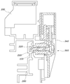
도 2는 도 1에 도시된 N 단 시프트락 기능을 구비한 변속 레버 시스템의 레버 하우징을 나타낸 도면.
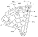
도 3은 도 1에 도시된 N 단 시프트락 기능을 구비한 변속 레버 시스템의 인게이징 레버를 나타낸 도면.
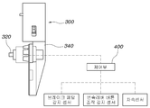
도 4는 도 1에 도시된 N 단 시프트락 기능을 구비한 변속 레버 시스템의 걸림기구를 나타낸 도면.
도 5는 도 1에 도시된 N 단 시프트락 기능을 구비한 변속 레버 시스템을 설명하기 위한 도면.1 is a view of a shift lever system having an N-shift lock function according to an embodiment of the present invention;
2 is a view showing a lever housing of a shift lever system having the N-stage shift lock function shown in FIG.
3 is a view showing an elevating lever of the shift lever system having the N-stage shift lock function shown in FIG.
Fig. 4 is a view showing the engagement mechanism of the shift lever system having the N-stage shift lock function shown in Fig. 1;
5 is a view for explaining a shift lever system having the N-stage shift lock function shown in FIG. 1;
이하에서는 첨부된 도면을 참조하여 본 발명의 바람직한 실시 예에 따른 N 단 시프트락 기능을 구비한 변속 레버 시스템에 대하여 살펴본다.Hereinafter, a shift lever system having an N-shift lock function according to a preferred embodiment of the present invention will be described with reference to the accompanying drawings.
도 1은 본 발명의 일 실시예에 따른 N 단 시프트락 기능을 구비한 변속 레버 시스템을 나타낸 도면이고, 도 2는 도 1에 도시된 N 단 시프트락 기능을 구비한 변속 레버 시스템의 레버 하우징을 나타낸 도면이며, 도 3은 도 1에 도시된 N 단 시프트락 기능을 구비한 변속 레버 시스템의 인게이징 레버를 나타낸 도면이고, 도 4는 도 1에 도시된 N 단 시프트락 기능을 구비한 변속 레버 시스템의 걸림기구를 나타낸 도면이며, 도 5는 도 1에 도시된 N 단 시프트락 기능을 구비한 변속 레버 시스템을 설명하기 위한 도면이다.FIG. 1 is a view showing a shift lever system having an N-stage shift lock function according to an embodiment of the present invention. FIG. 2 is a sectional view of the lever housing of the shift lever system having the N- FIG. 3 is a view showing an elevating lever of the shift lever system having the N-stage shift lock function shown in FIG. 1, and FIG. 4 is a view showing the shift lever of the shift lever system having the N-stage shift lock function shown in FIG. FIG. 5 is a view for explaining a shift lever system having the N-stage shift lock function shown in FIG. 1. FIG.
본 발명에 따른 N 단 시프트락 기능을 구비한 변속 레버 시스템은 도 1에 도시된 바와 같이, P, R, N, D 단 중 특정 변속단을 선택하는 변속 레버(10)가 회전 가능하게 설치된 레버 하우징(100); 변속 레버(10)와 일체로 이동되게 설치되고 D 단, N 단 및 P 단에 대해 걸림부(220)가 형성된 인게이징 레버(200); 및 레버 하우징(100)에서 걸림부(220)에 대응되게 설치된 것으로 P 단과 N 단 사이에서의 인게이징 레버(200)의 회전을 허용하거나 또는 구속하도록 동작하는 걸림기구(300);를 포함한다.1, a shift lever system having an N-stage shift lock function according to the present invention includes a
본 발명은 P, R, N, D 단이 직선적으로 배치되어 변속 레버(10)를 전후방향으로 조작시 변속이 수행되는 변속 장치에 적용될 수 있다. 단, 변속 레버(10)를 전후방향에 대해서 직선 조작하는 변속 구조의 경우 운전자의 오조작에 의해 D 단에서 P 단으로 한 번에 변속이 수행될 수 있고, 이를 제한하지 못할 경우 차량이 주행되는 상태에서 주차기구가 동작됨에 따라 주차기구를 이루는 구성품이 파손되는 문제가 발생될 수 있다.The present invention can be applied to a shift device in which P, R, N, and D stages are linearly arranged to perform shifting when the
본 발명은 이러한 문제를 해소하기 위한 것으로, 레버 하우징(100)에 변속 레버(10)가 인게이징 레버(200)와 함께 회전되게 설치되고, 특히 인게이징 레버(200)에는 D 단, N 단 및 P 단에 대해 걸림부(220)가 형성되며 레버 하우징(100)에는 걸림부(220)에 대응되게 설치된 걸림기구(300)가 설치됨으로써 걸림기구(300)가 N 단 또는 P 단 사이에서 인게이징 레버(200)의 회전을 구속함에 따라 변속 레버(10)가 회전되지 않도록 한다.In order to solve this problem, the present invention provides a lever housing (100) in which a shift lever (10) is installed to be rotated together with an inging lever (200), and in particular, an engaging lever (200) The
즉, 변속 레버(10)가 D 단에 위치된 상태에서, 운전자의 부주의에 의해 변속 레버(10)가 P 단을 향해 다이렉트로 변속시 N 단 위치에서 걸림기구(300)가 인게이징 레버(200)의 걸림부(220)에 걸림 연결되어 인게이징 레버(200)의 회전을 제한한다. 이로 인해, D 단에서 변속 레버(10)가 다이렉트로 이동시 N 단에서 인게이징 레버(200)와 함께 변속 레버(10)의 이동을 제한함으로써 주행 상태에서 P 단 체결에 의해 주차기구의 구성 요소들이 파손되지 않는다. 또한, 걸림기구(300)는 P 단에서 다른 변속단으로 변속시 시프트락 기능을 수행하는 것으로, 시프트락 기능을 수행하기 위해 마련된 걸림기구(300)를 이용함에 따라 별도 구성의 추가없이 무리한 P 단 변속을 제한하는 제어를 수행할 수 있다.That is, when the
하기에는 본 발명에 대해서 구체적으로 설명한다.Hereinafter, the present invention will be described in detail.
도 3에서 볼 수 있듯이, 인게이징 레버(200)는 레버 하우징(100)에서 회전 가능하도록 힌지 설치되고 변속 레버(10)가 결합된 회전부(200a)와, 회전부(200a)에 결합되고 부채꼴 형상으로 형성되며 걸림부(220)가 형성된 연결단부(200b)로 구성될 수 있다. 즉, 인게이징 레버(200)는 레버 하우징(100)에 힌지 설치됨에 따라 회전 가능하게 설치됨으로써 인게이징 레버(200)의 회전부(200a)에 결합되는 변속 레버(10)의 조작에 연동되어 회전될 수 있다. 회전부(200a)에는 변속 레버(10)에 설치되는 이동핀(14)이 구비될 수 있으며, 이동핀(14)은 스프링(16)에 의해 탄발 지지되게 설치될 수 있다. 여기서, 이동핀(14)의 경우 변속 레버(10)에 설치된 버튼(12)에 연동되어 상하 이동될 수 있으며, 하기 설명할 레버 하우징(100)의 걸림공간(140)에서 이동될 수 있다. 버튼(12)의 경우 변속 레버(10)에 결합되는 변속 노브에 구비될 수 있으며, 통상적으로 변속 레버(10)에는 노브가 구비되고 그 노브에 버튼(12)이 구비되는바, 그 구체적인 작동 구조에 대해서는 생략하였다.3, the
또한, 인게이징 레버(200)의 회전부(200a)에는 부채꼴 형상의 연결단부(200b)가 형성되고, 이 연결단부(200b)에 걸림부(220)가 형성될 수 있다. 즉, 걸림부(220)는 변속 레버(10)의 회전 방향으로 연장되게 형성되어야 하는바 부채꼴 형상의 연결단부(200b)에 형성되고, 연결단부(200b)에는 변속 레버(10)의 조작에 따른 조작감을 부여하기 위한 디텐트 구조(20)가 적용될 수 있다.In addition, a fan-shaped connecting
한편, 인게이징 레버(200)의 걸림부(220)는, D 단과 N 단에 사이에서 변속 레버(10)의 회전 방향으로 연장되며 걸림기구(300)가 걸리도록 함몰 형성된 제1걸림홈(222); R 단에 해당하며 걸림기구(300)가 걸리지 않도록 평면상으로 형성된 평면부(224); 및 P 단에 해당하며 걸림기구(300)가 걸리도록 함몰 형성된 제2걸림홈(226);을 포함한다.The
이렇게, 인게이징 레버(200)의 걸림부(220)는 도 3에 도시된 바와 같이, D 단과 N 단에 해당하는 제1걸림홈(222), R 단에 해당하는 평면부(224), P 단에 해당하는 제2걸림홈(226)으로 구성되고, 제1걸림홈(222), 평면부(224) 및 제2걸림홈(226)은 변속 레버의 회전방향에 대해 순차적으로 위치될 수 있다. 여기서, 제1걸림홈(222)의 경우 D 단과 N 단이 서로 연결되도록 장홈으로 형성되어 걸림기구(300)가 제1걸림홈(222)에 걸리더라도 D 단과 N 단에서는 변속 레버가 이동될 수 있다. 단, D 단에서 P 단으로 변속되는 경우 걸림기구(300)가 제1걸림홈(222)에 걸리어 이동이 제한되고, 걸림기구(300)의 동작에 의해 제1걸림홈(222)에서 이탈되어 인게이징 레버(200)의 회전이 허용되면 변속 레버(10)의 조작을 통해 P 단으로 변속을 수행할 수 있다. 이로 인해, D 단에서 다이렉트로 P 단으로 변속되는 것이 제한된다.3, the
반대로, P 단에서 다른 변속단 단으로 변속시 걸림기구(300)가 제2걸림홈(226)에 걸리어 시프트락 상태가 유지되고, 걸림기구(300)의 동작에 의해 제2걸림홈(226)에서 이탈되어 인게이징 레버(200)의 회전이 허용되면 변속 레버(10)의 조작을 통해 다른 변속단으로 변속을 수행할 수 있다.On the other hand, the
R 단에 해당하는 평면부(224)의 경우 인게이징 레버(200)의 단면과 평면을 이루도록 형성됨으로써 걸림기구(300)가 R 단에서는 인게이징 레버(200)의 회전을 구속하지 못하도록 이루어짐에 따라 변속 레버(10)가 N 단에서 P 단 또는 P 단에서 N 단으로 이동되게 할 수 있다. 즉, 변속 레버(10)를 조작하는 중 R 단에서도 걸림기구(300)에 걸리어 인게이징 레버(200)의 회전이 구속되는 경우 운전자의 의도와 다르게 후진 주행될 수 있는바, R 단에 해당해서는 평면부(224)를 형성하는 것이다.Since the
한편, 도 4에 도시된 바와 같이, 걸림기구(300)는 인게이징 레버(200)를 향해 인출되거나 또는 반대방향으로 인입되는 걸림핀(320)을 구비한 솔레노이드로 구성되고, 걸림핀(320)이 인출되어 걸림부(220)에 걸리게 되면 인게이징 레버(200)의 회전이 구속될 수 있다. 즉, 걸림기구(300)는 솔레노이드로서, 플런저인 걸림핀(320)이 인출되거나 또는 반대방향으로 인입되게 구성되며, 평상시에는 걸림부(220)에 걸리도록 걸림핀(320)이 인출된 상태가 유지되고 특정 상황에서 걸림핀(320)이 인입되어 걸림부(220)에서 이탈되도록 구성될 수 있다. 여기서, 걸림기구(300)는 하기에 설명할 제어부의 제어에 의해 제어될 수 있으며, 커넥터 및 전기선을 통해 전기 연결될 수 있다.4, the
상세하게, 도 2 및 도 5에 도시된 바와 같이, 레버 하우징(100)에는 인게이징 레버(200)의 걸림부(220)와 대응되는 위치에 관통홀(120)이 형성되고, 걸림기구(300)는 레버 하우징(100)에 고정되게 설치되며 솔레노이드가 결합된 케이스(340);를 더 포함하고, 솔레노이드의 걸림핀(320)은 관통홀(120)을 통해 인게이징 레버(200)를 향해 인출될 수 있다.2 and 5, a through
이처럼, 걸림기구(300)는 레버 하우징(100)의 관통홀(120)을 덮도록 설치되는 케이스(340)를 통해 레버 하우징(100)에 결합되고, 걸림기구(300)의 걸림핀(320)이 관통홀(120)을 통해 인게이징 레버(200)를 향해 인출됨으로써 걸림부(220)에 걸리도록 구성된다. 이렇게, 레버 하우징(100)에 관통홀(120)을 형성하고 케이스(340)를 통해 걸림기구(300)를 설치함으로써 레버 하우징(100)에서 인게이징 레버(200)와 걸림기구(300)가 간섭되지 않고, 인게이징 레버(200)에 형성된 걸림부(220)에 걸림기구(300)의 걸림핀(320)이 걸리도록 구성될 수 있다.The engaging
한편, 인게이징 레버(200)에는 변속 레버(10)에 설치된 버튼(12)에 연동되어 상하 이동되는 이동핀(14)이 구비되고, 레버 하우징(100)에는 이동핀(14)이 이동되는 걸림공간(140)이 형성되며 걸림공간(140)은 P, R, N, D 단 중 특정 변속단에서 이동핀(14)의 이동이 제한되게 형성될 수 있다.The shifting
여기서, 레버 하우징(100)의 걸림공간(140)은, 변속 레버(10)가 D 단 또는 N 단 선택시 이동핀(14)이 위치되는 제1걸림단(142); 변속 레버(10)가 R 단 선택시 이동핀(14)이 위치되며 제1걸림단(142)보다 상대적으로 더 돌출된 제2걸림단(144); 변속 레버(10)가 P 단 선택시 이동핀(14)이 위치되는 제3걸림단(146); 및 제2걸림단(144)과 제3걸림단(146) 사이에 위치되며 제2걸림단(144)보다 상대적으로 더 돌출된 걸림턱(148);을 포함할 수 있다.Here, the engaging
도 2에 도시된 바와 같이, 레버 하우징(100)의 걸림공간(140)은 제1걸림단(142), 제2걸림단(144), 제3걸림단(146), 걸림턱(148)으로 구성되며, 인게이징 레버(200)에 설치된 이동핀(14)이 걸림공간(140)에서 변속 레버(10)의 이동에 따라 제1걸림단(142), 제2걸림단(144), 제3걸림단(146) 중 어느 하나에 위치된다. 여기서, 변속 레버(10)에 설치된 버튼(12)은 변속 노브에 구비될 수 있으며, 이동핀(14)은 스프링(16)에 의해 탄성 지지되어 걸림공간(140)의 제1,2,3걸림단에 접촉된 상태가 유지되도록 구성될 수 있다.2, the latching
이로 인해, 변속 레버(10)가 D 단 또는 N 단 선택시 이동핀(14)은 제1걸림단(142)에 위치되고, 제1걸림단(142)의 경우 D 단과 N 단 영역이 이어지도록 형성됨에 따라 변속 레버(10)를 D 단에서 N 단으로 또는 N 단에서 D 단으로 조작시 버튼(12)을 누르지 않고 변속을 수행할 수 있다. 단, D 단 또는 N 단에서 R 단 또는 P 단으로 변속시 버튼(12)을 눌러야만 변속이 수행되도록 한다. 이를 위해, R 단에 해당하는 제2걸림단(144)은 제1걸림단(142)보다 상대적으로 더 돌출되게 형성되어 제1걸림단(142)과 제2걸림단(144)을 구분하고, P 단에 해당하는 제3걸림단(146)은 제2걸림단(144)보다 상대적으로 더 돌출된 걸림턱(148)에 의해 제2걸림단(144)과 구분되도록 한다.When the
이로 인해, 변속 레버(10)를 조작하여 변속시 D 단 또는 N 단은 제1걸림단(142)에서 버튼(12)을 누르지 않고도 변속이 가능하며, R 단 또는 P 단으로 변속시 버튼(12)을 눌러야만 이동핀(14)이 걸림공간(140)에서 이동되어 변속 레버(10)의 회전이 가능하도록 함으로써 변속 오조작이 방지되도록 한다.Thus, the
한편, 도 4에 도시된 바와 같이, 걸림기구(300)의 동작 여부를 제어하는 제어부(400);를 더 포함한다. 여기서, 제어부(400)는 브레이크 페달의 동작신호를 입력받아 걸림기구(300)의 동작을 제어하도록 구성되고 브레이크 페달의 동작신호가 발생되는 경우 걸림기구(300)에 의한 인게이징 레버(200)의 회전이 허용되도록 할 수 있다.4, a
이렇게, 걸림기구(300)는 제어부(400)의 의해 동작되며, 제어부(400)는 브레이크 페달의 동작신호가 발생된 경우에 한하여 걸림기구(300)가 동작되도록 하여 인게이징 레버(200)의 회전을 허용하거나 또는 구속한다.In this way, the
상세하게, 변속 레버(10)가 D 단에 위치된 상태에서, 운전자의 부주의로 인해 변속 레버(10)를 P 단으로 조작할 경우 걸림기구(300)에 의해 변속 레버(10)는 N 단까지만 변속이 허용된다. 즉, 걸림기구(300)가 인게이징 레버(200)의 걸림부(220)에 걸림에 따라 변속 레버(10)의 이동이 제한되는 것이다. 이로 인해, 운전자의 오조작에 의한 변속이 방지되고, 브레이크 페달을 조작함에 따른 브레이크 페달의 동작신호가 제어부(400)에 입력되는 경우 걸림기구(300)가 걸림부(220)에서 이탈되도록 동작됨으로써 브레이크 페달이 작동됨에 따라 차량이 정차된 상태에서만 P 단으로 변속이 수행될 수 있다.Specifically, when the
한편, 제어부(400)는 변속 레버(10)에 구비된 버튼(12)의 조작신호를 더 입력받아 걸림기구(300)의 동작을 제어하도록 구성되고 브레이크 페달의 동작신호 및 버튼(12)의 조작신호가 함께 발생되는 경우 인게이징 레버(200)의 회전이 허용되도록 걸림기구(300)의 동작을 제어할 수 있다.The
또한, 제어부(400)는 차속정보를 더 입력받아 걸림기구(300)의 동작을 제어하도록 구성되고 브레이크 페달의 동작신호, 버튼(12)의 조작신호와 함께 차속이 기설정된 설정속도 이하인 경우 인게이징 레버(200)의 회전이 허용되도록 걸림기구(300)의 동작을 제어할 수 있다.The
이와 같이, 제어부(400)는 브레이크 페달의 동작신호와 더불어 변속 레버(10)에 구비된 버튼(12)의 조작신호와 차속정보를 더 입력받고, 브레이크 페달의 동작신호와 버튼(12)의 조작신호 및 차속이 설정속도 이하인 경우를 모두 만족하는 경우 인게이징 레버(200)의 회전이 허용되도록 걸림기구(300)의 동작을 제어할 수 있다.The
즉, 걸림기구(300)가 인게이징 레버(200)의 걸림부(220)에 걸림에 따라 N 단에서 P 단으로의 변속이 제한되는데, 이를 허용하기 위해서는 브레이크 페달의 동작되어 차량이 정차되는지, 그리고 변속 레버(10)에 구비된 버튼(12)의 조작신호가 입력됨에 따라 운전자의 의도에 의해 P 단으로의 변속을 수행하는지, 그리고 차속이 설정속도 이하임에 따라 차량이 정차되었는지를 만족하는 경우에 한하도록 하는 것이다.That is, as the engaging
상기한 제어부(400)는 브레이크 페달의 감지센서, 변속 레버(10) 버튼(12)의 조작 감지센서, 차속센서로부터 각각의 정보를 입력받고, 브레이크 페달의 동작신호, 버튼(12)의 조작신호, 차속이 설정속도 이하인 조건을 모두 만족하는 경우 걸림기구(300)가 걸림부(220)에서 걸림 해제되도록 제어함으로써 차량의 정차 상태에서 P 단으로의 변속이 가능하도록 한다.The
상술한 바와 같은 구조로 이루어진 N 단 시프트락 기능을 구비한 변속 레버(10) 시스템에 따르면, D 단에서 P 단으로 변속이 수행되는 경우 N 단에서 변속 레버(10)의 회전을 제한하고, 이후 P 단으로의 변속이 허용되는 조건 만족시 변속 레버(10)가 회전되어 P 단으로 변속되도록 함으로써 운전자의 부주의로 인한 P 단 변속시 주차기구의 손상이 방지된다.According to the
본 발명은 특정한 실시예에 관련하여 도시하고 설명하였지만, 이하의 특허청구범위에 의해 제공되는 본 발명의 기술적 사상을 벗어나지 않는 한도 내에서, 본 발명이 다양하게 개량 및 변화될 수 있다는 것은 당 업계에서 통상의 지식을 가진 자에게 있어서 자명할 것이다.While the present invention has been particularly shown and described with reference to specific embodiments thereof, it will be understood by those skilled in the art that various changes in form and details may be made therein without departing from the spirit and scope of the invention as defined by the following claims It will be apparent to those of ordinary skill in the art.
100:레버 하우징 120:관통홀
140:걸림공간 142:제1걸림단
144:제2걸림단 146:제3걸림단
148:걸림턱 200:인게이징 레버
220:걸림부 222:제1걸림홈
224:평면부 226:제2걸림홈
300:걸림기구 320:걸림핀
340:케이스 400:제어부100: lever housing 120: through hole
140: latching space 142: first latching end
144: second hook 146: third hook
148: Engaging jaw 200: Engaging lever
220: engaging portion 222: first engaging groove
224: flat portion 226: second engaging groove
300: latching mechanism 320: latching pin
340: Case 400:
Claims (10)
변속 레버와 일체로 이동되게 설치되고 D 단, N 단 및 P 단에 대해 걸림부가 형성된 인게이징 레버; 및
레버 하우징에서 걸림부에 대응되게 설치된 것으로 P 단과 N 단 사이에서의 인게이징 레버의 회전을 허용하거나 또는 구속하도록 동작하는 걸림기구;를 포함하는 N 단 시프트락 기능을 구비한 변속 레버 시스템.A lever housing rotatably provided with a shift lever for selecting a specific shift position among the P, R, N, and D stages;
An engaging lever which is provided so as to be moved integrally with the shift lever and has a latching portion for the D-stage, N-stage and P-stage; And
And an engagement mechanism that is provided to correspond to the engagement portion in the lever housing and operates to allow or restrict rotation of the engagement lever between the P-stage and the N-stage.
인게이징 레버의 걸림부는,
D 단과 N 단에 사이에서 변속 레버의 회전 방향으로 연장되며 걸림기구가 걸리도록 함몰 형성된 제1걸림홈;
R 단에 해당하며 걸림기구가 걸리지 않도록 평면상으로 형성된 평면부; 및
P 단에 해당하며 걸림기구가 걸리도록 함몰 형성된 제2걸림홈;을 포함하는 것을 특징으로 하는 N 단 시프트락 기능을 구비한 변속 레버 시스템.The method according to claim 1,
The engaging portion of the energizing lever
A first latching groove extending between the D-stage and the N-stage and extending in the rotational direction of the shift lever, the first latching groove being formed to be engaged with the latching mechanism;
A planar portion corresponding to the R-stage and formed in a plane shape so that the latching mechanism is not caught; And
And a second engaging groove formed in the second engaging groove so as to be engaged with the engaging mechanism.
걸림기구는 인게이징 레버를 향해 인출되거나 또는 반대방향으로 인입되는 걸림핀을 구비한 솔레노이드로 구성되고,
걸림핀이 인출되어 걸림부에 걸리게 되면 인게이징 레버의 회전이 구속되는 것을 특징으로 하는 N 단 시프트락 기능을 구비한 변속 레버 시스템.The method according to claim 1,
The latching mechanism is constituted by a solenoid having a latching pin which is pulled out toward the engaging lever or is pulled in the opposite direction,
Wherein the rotation of the engagement lever is restricted when the engagement pin is drawn out and caught by the engagement portion.
레버 하우징에는 인게이징 레버의 걸림부와 대응되는 위치에 관통홀이 형성되고,
걸림기구는 레버 하우징에 고정되게 설치되며 솔레노이드가 결합된 케이스;를 더 포함하고,
솔레노이드의 걸림핀은 관통홀을 통해 인게이징 레버를 향해 인출되는 것을 특징으로 하는 N 단 시프트락 기능을 구비한 변속 레버 시스템.The method according to claim 1,
A through hole is formed in the lever housing at a position corresponding to the engaging portion of the engaging lever,
The latch mechanism further includes a case fixedly attached to the lever housing and coupled with the solenoid,
And the engaging pin of the solenoid is pulled out through the through hole toward the engaging lever.
인게이징 레버에는 변속 레버에 설치된 버튼에 연동되어 상하 이동되는 이동핀이 구비되고,
레버 하우징에는 이동핀이 이동되는 걸림공간이 형성되며 걸림공간은 P, R, N, D 단 중 특정 변속단에서 이동핀의 이동이 제한되게 형성된 것을 특징으로 하는 N 단 시프트락 기능을 구비한 변속 레버 시스템.The method according to claim 1,
The energizing lever is provided with a moving pin that moves up and down in association with a button provided on the shift lever,
Wherein the lever housing is formed with an engagement space through which the movement pin is moved, and the engagement space is formed so that movement of the movement pin is limited in a specific one of the P, R, N, Lever system.
레버 하우징의 걸림공간은,
변속 레버가 D 단 또는 N 단 선택시 이동핀이 위치되는 제1걸림단;
변속 레버가 R 단 선택시 이동핀이 위치되며 제1걸림단보다 상대적으로 더 돌출된 제2걸림단;
변속 레버가 P 단 선택시 이동핀이 위치되는 제3걸림단; 및
제2걸림단과 제3걸림단 사이에 위치되며 제2걸림단보다 상대적으로 더 돌출된 걸림턱;을 포함하는 것을 특징으로 하는 N 단 시프트락 기능을 구비한 변속 레버 시스템.The method of claim 5,
The engaging space of the lever housing,
A first latching end in which the shift pin is positioned in the D-step or N-step selection of the shift lever;
When the shift lever is selected in the R-stage, the shifting pin is positioned and the second latching end is relatively more protruded than the first latching end;
A third latching end in which the shift pin is positioned when the shift lever is selected in the P-stage; And
And an engaging jaw located between the second engaging end and the third engaging end and relatively more protruded than the second engaging end.
변속 레버의 이동핀은 스프링에 의해 탄발 지지되게 설치된 것을 특징으로 하는 N 단 시프트락 기능을 구비한 변속 레버 시스템.The method of claim 6,
And the shift pin of the shift lever is elastically supported by a spring.
걸림기구의 동작 여부를 제어하는 제어부;를 더 포함하며,
제어부는 브레이크 페달의 동작신호를 입력받아 걸림기구의 동작을 제어하도록 구성되고 브레이크 페달의 동작신호가 발생되는 경우 걸림기구에 의한 인게이징 레버의 회전이 허용되도록 하는 것을 특징으로 하는 N 단 시프트락 기능을 구비한 변속 레버 시스템.The method according to claim 1,
And a control unit for controlling whether or not the latching mechanism is operated,
Wherein the control unit is configured to receive the operation signal of the brake pedal and to control the operation of the engagement mechanism, and to allow rotation of the engagement lever by the engagement mechanism when an operation signal of the brake pedal is generated. (20).
제어부는 변속 레버에 구비된 버튼의 조작신호를 더 입력받아 걸림기구의 동작을 제어하도록 구성되고 브레이크 페달의 동작신호 및 버튼의 조작신호가 함께 발생되는 경우 인게이징 레버의 회전이 허용되도록 걸림기구의 동작을 제어하는 것을 특징으로 하는 N 단 시프트락 기능을 구비한 변속 레버 시스템.The method of claim 8,
The control unit is further configured to receive the operation signal of the button provided on the shift lever and to control the operation of the engagement mechanism. When the operation signal of the brake pedal and the operation signal of the button are generated together, And the operation of the shift lever system is controlled.
제어부는 차속정보를 더 입력받아 걸림기구의 동작을 제어하도록 구성되고 브레이크 페달의 동작신호, 버튼의 조작신호와 함께 차속이 기설정된 설정속도 이하인 경우 인게이징 레버의 회전이 허용되도록 걸림기구의 동작을 제어하는 것을 특징으로 하는 N 단 시프트락 기능을 구비한 변속 레버 시스템.The method of claim 9,
The control unit is further configured to receive the vehicle speed information and to control the operation of the latching mechanism and to control the operation of the latching mechanism so that rotation of the engaging lever is permitted when the vehicle speed is equal to or lower than a predetermined speed, Speed shift lock function.
Priority Applications (3)
| Application Number | Priority Date | Filing Date | Title |
|---|---|---|---|
| KR1020170025028A KR102412104B1 (en) | 2017-02-24 | 2017-02-24 | Transmission lever having n range shift lock |
| US15/828,247 US10663060B2 (en) | 2017-02-24 | 2017-11-30 | Shift lever mechanism having neutral range shift lock |
| CN201711278661.0A CN108506467B (en) | 2017-02-24 | 2017-12-06 | Shift Lever Mechanism with Neutral Shift Lock |
Applications Claiming Priority (1)
| Application Number | Priority Date | Filing Date | Title |
|---|---|---|---|
| KR1020170025028A KR102412104B1 (en) | 2017-02-24 | 2017-02-24 | Transmission lever having n range shift lock |
Publications (2)
| Publication Number | Publication Date |
|---|---|
| KR20180098457A true KR20180098457A (en) | 2018-09-04 |
| KR102412104B1 KR102412104B1 (en) | 2022-06-23 |
Family
ID=63246126
Family Applications (1)
| Application Number | Title | Priority Date | Filing Date |
|---|---|---|---|
| KR1020170025028A Active KR102412104B1 (en) | 2017-02-24 | 2017-02-24 | Transmission lever having n range shift lock |
Country Status (3)
| Country | Link |
|---|---|
| US (1) | US10663060B2 (en) |
| KR (1) | KR102412104B1 (en) |
| CN (1) | CN108506467B (en) |
Families Citing this family (5)
| Publication number | Priority date | Publication date | Assignee | Title |
|---|---|---|---|---|
| EP3511597B1 (en) * | 2018-01-15 | 2020-02-26 | FCA Italy S.p.A. | Control device for a vehicle gearshift |
| CN109185451A (en) * | 2018-09-21 | 2019-01-11 | 奇瑞汽车股份有限公司 | A kind of automatic catch gearshift P gear protection structure and automobile |
| CN111216550A (en) * | 2020-01-08 | 2020-06-02 | 江铃汽车股份有限公司 | Gear shifting control method for automobile monostable gear shifter |
| WO2024000126A1 (en) * | 2022-06-27 | 2024-01-04 | Ghsp, Inc. | Selection assembly for a vehicle that includes a park blocker and neutral blocker that are operated by a single actuator |
| CN115949735A (en) * | 2022-12-30 | 2023-04-11 | 湖北三江航天万山特种车辆有限公司 | A limit structure of a gear selector, a structure of a gear selector, a limit method and a vehicle |
Citations (4)
| Publication number | Priority date | Publication date | Assignee | Title |
|---|---|---|---|---|
| KR20000015335A (en) * | 1998-08-28 | 2000-03-15 | 김태구 | Shifting control device of automatic transmission having manual speed change function |
| US6325196B1 (en) * | 1999-07-29 | 2001-12-04 | Grand Haven Stamped Products, Division Of Jsj Corporation | Shifter with park lock and neutral lock device |
| KR20050022378A (en) | 2003-08-30 | 2005-03-08 | 현대자동차주식회사 | Connecting apparatus for parking lever and auto transmission lever |
| US20060016287A1 (en) * | 2004-07-26 | 2006-01-26 | Grossman Patrick S | Shifter having neutral lock |
Family Cites Families (19)
| Publication number | Priority date | Publication date | Assignee | Title |
|---|---|---|---|---|
| JPH0518459A (en) * | 1991-07-12 | 1993-01-26 | Tokai Rika Co Ltd | Shift lever locking device of automatic tranmission |
| JP2573449B2 (en) * | 1991-12-20 | 1997-01-22 | 池田物産株式会社 | Safety devices for vehicle passenger seats |
| JPH06229467A (en) * | 1993-02-02 | 1994-08-16 | Fuji Kiko Co Ltd | Shift lock device |
| US5489246A (en) * | 1994-08-29 | 1996-02-06 | Pontiac Coil, Inc. | Electronic park lock |
| US5582073A (en) * | 1994-09-26 | 1996-12-10 | Tsuda Kogyo Kabushiki Kaisha | Shift lever assembly for automatic transmission |
| JP3627940B2 (en) * | 1995-06-15 | 2005-03-09 | 富士機工株式会社 | Shift lock mechanism of shift lever device |
| JPH0966820A (en) * | 1995-09-04 | 1997-03-11 | Mitsubishi Automob Eng Co Ltd | Automotive brake equipment |
| US5993353A (en) * | 1997-12-15 | 1999-11-30 | Hyundai Motor Company, Ltd. | Shift lever device for an automatic transmission of a vehicle |
| US6189398B1 (en) * | 1998-02-27 | 2001-02-20 | Fuji Koko Co., Ltd. | Shift-lever devices |
| JP3688923B2 (en) * | 1999-02-09 | 2005-08-31 | 株式会社東海理化電機製作所 | Shift lever device |
| JP3691681B2 (en) * | 1999-03-24 | 2005-09-07 | 株式会社東海理化電機製作所 | Shift lever device |
| JP3532118B2 (en) * | 1999-05-31 | 2004-05-31 | 富士機工株式会社 | Shift lock mechanism of shift lever device |
| JP2001113974A (en) * | 1999-10-20 | 2001-04-24 | Tokai Rika Co Ltd | Shift lever device |
| US20060032723A1 (en) * | 2004-08-12 | 2006-02-16 | Wilber Darrin F | BTSI with lead frame switch |
| JP4695928B2 (en) * | 2005-06-29 | 2011-06-08 | ホシデン株式会社 | Locking device |
| KR20140008648A (en) * | 2012-07-11 | 2014-01-22 | 현대자동차주식회사 | Apparatus for electronic control transmission for vehicle |
| JP6557135B2 (en) * | 2015-12-25 | 2019-08-07 | トヨタ自動車株式会社 | Shift lever device |
| US20170335957A1 (en) * | 2016-05-17 | 2017-11-23 | Dura Operating, Llc | Transmission shifter with multi-position lockout |
| US10415700B2 (en) * | 2017-02-07 | 2019-09-17 | Thyssenkrupp Ag | Column shifter park lock and park detect switch mechanism |
-
2017
- 2017-02-24 KR KR1020170025028A patent/KR102412104B1/en active Active
- 2017-11-30 US US15/828,247 patent/US10663060B2/en active Active
- 2017-12-06 CN CN201711278661.0A patent/CN108506467B/en active Active
Patent Citations (4)
| Publication number | Priority date | Publication date | Assignee | Title |
|---|---|---|---|---|
| KR20000015335A (en) * | 1998-08-28 | 2000-03-15 | 김태구 | Shifting control device of automatic transmission having manual speed change function |
| US6325196B1 (en) * | 1999-07-29 | 2001-12-04 | Grand Haven Stamped Products, Division Of Jsj Corporation | Shifter with park lock and neutral lock device |
| KR20050022378A (en) | 2003-08-30 | 2005-03-08 | 현대자동차주식회사 | Connecting apparatus for parking lever and auto transmission lever |
| US20060016287A1 (en) * | 2004-07-26 | 2006-01-26 | Grossman Patrick S | Shifter having neutral lock |
Also Published As
| Publication number | Publication date |
|---|---|
| KR102412104B1 (en) | 2022-06-23 |
| US10663060B2 (en) | 2020-05-26 |
| CN108506467A (en) | 2018-09-07 |
| CN108506467B (en) | 2021-04-27 |
| US20180245690A1 (en) | 2018-08-30 |
Similar Documents
| Publication | Publication Date | Title |
|---|---|---|
| KR101575414B1 (en) | Shifting apparatus for vehicle | |
| KR20180098457A (en) | Transmission lever having n range shift lock | |
| KR102497038B1 (en) | Shift control apparatus for electronic shift system | |
| KR101755854B1 (en) | Electronic shift system | |
| CN102086931B (en) | Shifting range sensing apparatus | |
| US9360108B2 (en) | Gear shift lever lock system and method | |
| US20190032772A1 (en) | Electronic transmission system | |
| KR102238050B1 (en) | Button type electronic shift lever system | |
| JP2015107671A (en) | Shift device | |
| KR20090118048A (en) | Actuator with shift lever actuator | |
| WO2017135218A1 (en) | Shift device | |
| KR20190050374A (en) | Shift control method for electronic shifting apparatus | |
| KR102676723B1 (en) | Dial type shift control apparatus for electronic shift system | |
| KR102659241B1 (en) | Shift lever of dial type | |
| JP6003785B2 (en) | Vehicle shift device | |
| KR102522916B1 (en) | Automotive tranmission | |
| KR20180005049A (en) | Electronic shift system | |
| KR102392555B1 (en) | Automotive transmission | |
| KR101704268B1 (en) | Button type electronic shift lever system | |
| JP2021160587A (en) | Shift lever device | |
| JP2017019341A (en) | Vehicular shift device | |
| KR100476267B1 (en) | Shift lever safety system for auto transmission | |
| JP7218999B2 (en) | Operation lever device for automatic transmission | |
| KR20180070193A (en) | Shift-lock system of shift-lever for automatic transmission | |
| KR101989073B1 (en) | Inhibitor switch for automatic transmission |
Legal Events
| Date | Code | Title | Description |
|---|---|---|---|
| PA0109 | Patent application |
Patent event code: PA01091R01D Comment text: Patent Application Patent event date: 20170224 |
|
| PG1501 | Laying open of application | ||
| A201 | Request for examination | ||
| PA0201 | Request for examination |
Patent event code: PA02012R01D Patent event date: 20191210 Comment text: Request for Examination of Application Patent event code: PA02011R01I Patent event date: 20170224 Comment text: Patent Application |
|
| E902 | Notification of reason for refusal | ||
| PE0902 | Notice of grounds for rejection |
Comment text: Notification of reason for refusal Patent event date: 20210309 Patent event code: PE09021S01D |
|
| E90F | Notification of reason for final refusal | ||
| PE0902 | Notice of grounds for rejection |
Comment text: Final Notice of Reason for Refusal Patent event date: 20210917 Patent event code: PE09021S02D |
|
| E701 | Decision to grant or registration of patent right | ||
| PE0701 | Decision of registration |
Patent event code: PE07011S01D Comment text: Decision to Grant Registration Patent event date: 20220323 |
|
| GRNT | Written decision to grant | ||
| PR0701 | Registration of establishment |
Comment text: Registration of Establishment Patent event date: 20220617 Patent event code: PR07011E01D |
|
| PR1002 | Payment of registration fee |
Payment date: 20220620 End annual number: 3 Start annual number: 1 |
|
| PG1601 | Publication of registration | ||
| PR1001 | Payment of annual fee |
Payment date: 20250526 Start annual number: 4 End annual number: 4 |