KR20180098401A - Structured Elements and Usage - Google Patents
Structured Elements and Usage Download PDFInfo
- Publication number
- KR20180098401A KR20180098401A KR1020187021988A KR20187021988A KR20180098401A KR 20180098401 A KR20180098401 A KR 20180098401A KR 1020187021988 A KR1020187021988 A KR 1020187021988A KR 20187021988 A KR20187021988 A KR 20187021988A KR 20180098401 A KR20180098401 A KR 20180098401A
- Authority
- KR
- South Korea
- Prior art keywords
- stream
- unit
- structuring element
- structured
- contact surface
- Prior art date
- Legal status (The legal status is an assumption and is not a legal conclusion. Google has not performed a legal analysis and makes no representation as to the accuracy of the status listed.)
- Ceased
Links
- 238000000034 method Methods 0.000 claims abstract description 50
- 238000009826 distribution Methods 0.000 claims abstract description 30
- 238000000638 solvent extraction Methods 0.000 claims abstract description 26
- 230000008569 process Effects 0.000 claims abstract description 23
- 238000001914 filtration Methods 0.000 claims description 22
- 230000000116 mitigating effect Effects 0.000 claims description 17
- 238000004519 manufacturing process Methods 0.000 claims description 8
- 239000004215 Carbon black (E152) Substances 0.000 claims description 2
- 229930195733 hydrocarbon Natural products 0.000 claims description 2
- 150000002430 hydrocarbons Chemical class 0.000 claims description 2
- 238000012994 industrial processing Methods 0.000 claims 1
- 229910010272 inorganic material Inorganic materials 0.000 claims 1
- 239000011147 inorganic material Substances 0.000 claims 1
- 239000000463 material Substances 0.000 abstract description 44
- 238000012423 maintenance Methods 0.000 abstract description 5
- 230000001788 irregular Effects 0.000 abstract description 4
- 210000004027 cell Anatomy 0.000 description 40
- 238000012545 processing Methods 0.000 description 29
- 239000003054 catalyst Substances 0.000 description 11
- 239000002245 particle Substances 0.000 description 9
- 230000006870 function Effects 0.000 description 8
- 230000001965 increasing effect Effects 0.000 description 8
- 230000008901 benefit Effects 0.000 description 7
- 239000011148 porous material Substances 0.000 description 6
- 230000014759 maintenance of location Effects 0.000 description 5
- 230000003746 surface roughness Effects 0.000 description 5
- 230000003197 catalytic effect Effects 0.000 description 4
- 239000000919 ceramic Substances 0.000 description 4
- 239000000356 contaminant Substances 0.000 description 4
- 238000006243 chemical reaction Methods 0.000 description 3
- 239000013626 chemical specie Substances 0.000 description 3
- 238000011176 pooling Methods 0.000 description 3
- 238000000926 separation method Methods 0.000 description 3
- 238000001179 sorption measurement Methods 0.000 description 3
- 230000002776 aggregation Effects 0.000 description 2
- 238000004220 aggregation Methods 0.000 description 2
- 230000015556 catabolic process Effects 0.000 description 2
- 230000001413 cellular effect Effects 0.000 description 2
- 238000004140 cleaning Methods 0.000 description 2
- 230000000052 comparative effect Effects 0.000 description 2
- 238000010276 construction Methods 0.000 description 2
- 230000000875 corresponding effect Effects 0.000 description 2
- 230000009849 deactivation Effects 0.000 description 2
- 238000006731 degradation reaction Methods 0.000 description 2
- 238000013461 design Methods 0.000 description 2
- 230000000694 effects Effects 0.000 description 2
- 238000000605 extraction Methods 0.000 description 2
- 239000010419 fine particle Substances 0.000 description 2
- 239000012530 fluid Substances 0.000 description 2
- 230000007246 mechanism Effects 0.000 description 2
- 229910052751 metal Inorganic materials 0.000 description 2
- 239000002184 metal Substances 0.000 description 2
- 239000000203 mixture Substances 0.000 description 2
- 238000012986 modification Methods 0.000 description 2
- 230000004048 modification Effects 0.000 description 2
- 239000000047 product Substances 0.000 description 2
- 239000010409 thin film Substances 0.000 description 2
- 238000012546 transfer Methods 0.000 description 2
- 238000010977 unit operation Methods 0.000 description 2
- MBMLMWLHJBBADN-UHFFFAOYSA-N Ferrous sulfide Chemical compound [Fe]=S MBMLMWLHJBBADN-UHFFFAOYSA-N 0.000 description 1
- 229910000831 Steel Inorganic materials 0.000 description 1
- 230000009471 action Effects 0.000 description 1
- 239000011149 active material Substances 0.000 description 1
- 239000003463 adsorbent Substances 0.000 description 1
- 230000002411 adverse Effects 0.000 description 1
- WYTGDNHDOZPMIW-RCBQFDQVSA-N alstonine Natural products C1=CC2=C3C=CC=CC3=NC2=C2N1C[C@H]1[C@H](C)OC=C(C(=O)OC)[C@H]1C2 WYTGDNHDOZPMIW-RCBQFDQVSA-N 0.000 description 1
- 229910052785 arsenic Inorganic materials 0.000 description 1
- RQNWIZPPADIBDY-UHFFFAOYSA-N arsenic atom Chemical compound [As] RQNWIZPPADIBDY-UHFFFAOYSA-N 0.000 description 1
- 238000011001 backwashing Methods 0.000 description 1
- 230000015572 biosynthetic process Effects 0.000 description 1
- 238000006555 catalytic reaction Methods 0.000 description 1
- 239000007795 chemical reaction product Substances 0.000 description 1
- 238000000576 coating method Methods 0.000 description 1
- 230000002596 correlated effect Effects 0.000 description 1
- 230000000593 degrading effect Effects 0.000 description 1
- 238000011161 development Methods 0.000 description 1
- 230000018109 developmental process Effects 0.000 description 1
- 238000010586 diagram Methods 0.000 description 1
- 238000004821 distillation Methods 0.000 description 1
- 238000011143 downstream manufacturing Methods 0.000 description 1
- 230000002708 enhancing effect Effects 0.000 description 1
- 239000010408 film Substances 0.000 description 1
- 238000005189 flocculation Methods 0.000 description 1
- 230000016615 flocculation Effects 0.000 description 1
- 238000011010 flushing procedure Methods 0.000 description 1
- 239000006260 foam Substances 0.000 description 1
- 230000006872 improvement Effects 0.000 description 1
- 238000009434 installation Methods 0.000 description 1
- 230000002045 lasting effect Effects 0.000 description 1
- 239000007788 liquid Substances 0.000 description 1
- 238000011068 loading method Methods 0.000 description 1
- 238000002156 mixing Methods 0.000 description 1
- 238000006386 neutralization reaction Methods 0.000 description 1
- 239000011236 particulate material Substances 0.000 description 1
- 238000005192 partition Methods 0.000 description 1
- 239000002574 poison Substances 0.000 description 1
- 231100000614 poison Toxicity 0.000 description 1
- 238000011084 recovery Methods 0.000 description 1
- 230000009467 reduction Effects 0.000 description 1
- 230000008929 regeneration Effects 0.000 description 1
- 238000011069 regeneration method Methods 0.000 description 1
- 230000004044 response Effects 0.000 description 1
- 239000004576 sand Substances 0.000 description 1
- 230000009919 sequestration Effects 0.000 description 1
- 239000007787 solid Substances 0.000 description 1
- 239000002594 sorbent Substances 0.000 description 1
- 239000010959 steel Substances 0.000 description 1
- 239000000126 substance Substances 0.000 description 1
- 231100000331 toxic Toxicity 0.000 description 1
- 230000002588 toxic effect Effects 0.000 description 1
- 230000009466 transformation Effects 0.000 description 1
- 238000011144 upstream manufacturing Methods 0.000 description 1
- 229910052720 vanadium Inorganic materials 0.000 description 1
- LEONUFNNVUYDNQ-UHFFFAOYSA-N vanadium atom Chemical compound [V] LEONUFNNVUYDNQ-UHFFFAOYSA-N 0.000 description 1
- 239000011800 void material Substances 0.000 description 1
Images


Classifications
-
- B—PERFORMING OPERATIONS; TRANSPORTING
- B01—PHYSICAL OR CHEMICAL PROCESSES OR APPARATUS IN GENERAL
- B01D—SEPARATION
- B01D21/00—Separation of suspended solid particles from liquids by sedimentation
- B01D21/0087—Settling tanks provided with means for ensuring a special flow pattern, e.g. even inflow or outflow
-
- B—PERFORMING OPERATIONS; TRANSPORTING
- B01—PHYSICAL OR CHEMICAL PROCESSES OR APPARATUS IN GENERAL
- B01D—SEPARATION
- B01D21/00—Separation of suspended solid particles from liquids by sedimentation
- B01D21/0012—Settling tanks making use of filters, e.g. by floating layers of particulate material
-
- B—PERFORMING OPERATIONS; TRANSPORTING
- B01—PHYSICAL OR CHEMICAL PROCESSES OR APPARATUS IN GENERAL
- B01D—SEPARATION
- B01D3/00—Distillation or related exchange processes in which liquids are contacted with gaseous media, e.g. stripping
- B01D3/008—Liquid distribution
-
- B—PERFORMING OPERATIONS; TRANSPORTING
- B01—PHYSICAL OR CHEMICAL PROCESSES OR APPARATUS IN GENERAL
- B01J—CHEMICAL OR PHYSICAL PROCESSES, e.g. CATALYSIS OR COLLOID CHEMISTRY; THEIR RELEVANT APPARATUS
- B01J19/00—Chemical, physical or physico-chemical processes in general; Their relevant apparatus
- B01J19/30—Loose or shaped packing elements, e.g. Raschig rings or Berl saddles, for pouring into the apparatus for mass or heat transfer
-
- B—PERFORMING OPERATIONS; TRANSPORTING
- B01—PHYSICAL OR CHEMICAL PROCESSES OR APPARATUS IN GENERAL
- B01J—CHEMICAL OR PHYSICAL PROCESSES, e.g. CATALYSIS OR COLLOID CHEMISTRY; THEIR RELEVANT APPARATUS
- B01J2219/00—Chemical, physical or physico-chemical processes in general; Their relevant apparatus
- B01J2219/30—Details relating to random packing elements
- B01J2219/302—Basic shape of the elements
- B01J2219/30207—Sphere
-
- B—PERFORMING OPERATIONS; TRANSPORTING
- B01—PHYSICAL OR CHEMICAL PROCESSES OR APPARATUS IN GENERAL
- B01J—CHEMICAL OR PHYSICAL PROCESSES, e.g. CATALYSIS OR COLLOID CHEMISTRY; THEIR RELEVANT APPARATUS
- B01J2219/00—Chemical, physical or physico-chemical processes in general; Their relevant apparatus
- B01J2219/30—Details relating to random packing elements
- B01J2219/302—Basic shape of the elements
- B01J2219/30238—Tetrahedron
-
- B—PERFORMING OPERATIONS; TRANSPORTING
- B01—PHYSICAL OR CHEMICAL PROCESSES OR APPARATUS IN GENERAL
- B01J—CHEMICAL OR PHYSICAL PROCESSES, e.g. CATALYSIS OR COLLOID CHEMISTRY; THEIR RELEVANT APPARATUS
- B01J2219/00—Chemical, physical or physico-chemical processes in general; Their relevant apparatus
- B01J2219/30—Details relating to random packing elements
- B01J2219/302—Basic shape of the elements
- B01J2219/30246—Square or square-derived
-
- B—PERFORMING OPERATIONS; TRANSPORTING
- B01—PHYSICAL OR CHEMICAL PROCESSES OR APPARATUS IN GENERAL
- B01J—CHEMICAL OR PHYSICAL PROCESSES, e.g. CATALYSIS OR COLLOID CHEMISTRY; THEIR RELEVANT APPARATUS
- B01J2219/00—Chemical, physical or physico-chemical processes in general; Their relevant apparatus
- B01J2219/30—Details relating to random packing elements
- B01J2219/302—Basic shape of the elements
- B01J2219/30269—Brush
-
- B—PERFORMING OPERATIONS; TRANSPORTING
- B01—PHYSICAL OR CHEMICAL PROCESSES OR APPARATUS IN GENERAL
- B01J—CHEMICAL OR PHYSICAL PROCESSES, e.g. CATALYSIS OR COLLOID CHEMISTRY; THEIR RELEVANT APPARATUS
- B01J2219/00—Chemical, physical or physico-chemical processes in general; Their relevant apparatus
- B01J2219/30—Details relating to random packing elements
- B01J2219/304—Composition or microstructure of the elements
- B01J2219/30416—Ceramic
-
- B—PERFORMING OPERATIONS; TRANSPORTING
- B01—PHYSICAL OR CHEMICAL PROCESSES OR APPARATUS IN GENERAL
- B01J—CHEMICAL OR PHYSICAL PROCESSES, e.g. CATALYSIS OR COLLOID CHEMISTRY; THEIR RELEVANT APPARATUS
- B01J2219/00—Chemical, physical or physico-chemical processes in general; Their relevant apparatus
- B01J2219/30—Details relating to random packing elements
- B01J2219/304—Composition or microstructure of the elements
- B01J2219/30475—Composition or microstructure of the elements comprising catalytically active material
-
- B—PERFORMING OPERATIONS; TRANSPORTING
- B01—PHYSICAL OR CHEMICAL PROCESSES OR APPARATUS IN GENERAL
- B01J—CHEMICAL OR PHYSICAL PROCESSES, e.g. CATALYSIS OR COLLOID CHEMISTRY; THEIR RELEVANT APPARATUS
- B01J2219/00—Chemical, physical or physico-chemical processes in general; Their relevant apparatus
- B01J2219/30—Details relating to random packing elements
- B01J2219/304—Composition or microstructure of the elements
- B01J2219/30483—Fibrous materials
-
- B—PERFORMING OPERATIONS; TRANSPORTING
- B01—PHYSICAL OR CHEMICAL PROCESSES OR APPARATUS IN GENERAL
- B01J—CHEMICAL OR PHYSICAL PROCESSES, e.g. CATALYSIS OR COLLOID CHEMISTRY; THEIR RELEVANT APPARATUS
- B01J2219/00—Chemical, physical or physico-chemical processes in general; Their relevant apparatus
- B01J2219/30—Details relating to random packing elements
- B01J2219/304—Composition or microstructure of the elements
- B01J2219/30491—Foam like materials
Landscapes
- Chemical & Material Sciences (AREA)
- Chemical Kinetics & Catalysis (AREA)
- Physics & Mathematics (AREA)
- Thermal Sciences (AREA)
- Organic Chemistry (AREA)
- Filtering Materials (AREA)
- Physical Or Chemical Processes And Apparatus (AREA)
- Immobilizing And Processing Of Enzymes And Microorganisms (AREA)
- Vaporization, Distillation, Condensation, Sublimation, And Cold Traps (AREA)
- Medicines Containing Material From Animals Or Micro-Organisms (AREA)
- Filtration Of Liquid (AREA)
- Solid-Sorbent Or Filter-Aiding Compositions (AREA)
- Micro-Organisms Or Cultivation Processes Thereof (AREA)
- Prostheses (AREA)
- Materials For Medical Uses (AREA)
- Peptides Or Proteins (AREA)
- Crystals, And After-Treatments Of Crystals (AREA)
Abstract
스트림 유동 분할 및 분배와 종래에 이용 가능한 재료를 초과하는 원하지 않는 종의 완화를 위한 구조화 요소가 제공된다. 구조화 요소는 공정 유동에서 원하지 않는 종의 표면 인력, 유지 및 유착 기회를 증가시킨다. 구조화 요소의 기능적 접촉 표면은 셀의 하나 이상의 면, 셀을 연결하는 스트럿 표면, 스트럿을 연결하는 노드의 표면 및 재료 표면의 채널, 플루트, 스파이크, 피브릴 또는 필리멘트에 의해 야기되는 돌기 또는 불규칙면의 표면을 포함할 수 있다.Structural elements are provided for stream flow partitioning and distribution and for the relaxation of undesired species in excess of the conventionally available materials. The structuring element increases the surface attraction, maintenance and adhesion opportunities of unwanted species in the process flow. The functional contact surface of the structuring element can be a surface or surfaces of one or more of the cells, a strut surface connecting the cells, a surface of the node connecting the struts and a channel on the material surface, a protrusion or irregular surface caused by flutes, spikes, fibrils or filings As shown in FIG.
Description
본 출원은 2015년 12월 31일자로 출원된 미국 잠정출원 제 62/273,590호 및 2016년 2월 12일자로 출원된 미국 잠정출원 제 62/294,718호의 장점 및 우선권 이익을 청구하며, 이들의 전체 내용은 본 명세서에 참고로 포함된다.This application claims priority to and benefit from United States Provisional Application No. 62 / 273,590, filed December 31, 2015, and Provisional Application No. 62 / 294,718, filed February 12, 2016, Are incorporated herein by reference.
현재 개시된 주제는 공정 유닛에서 및/또는 공정 유닛 내에서 스트림의 강화된 처리를 위한 재료 및 방법에 관한 것이다.The presently disclosed subject matter relates to materials and methods for enhanced processing of streams in process units and / or process units.
설비에 포함된 공정 유닛의 효율 및 경제성을 향상시키기 위해, 산업 설비에서 공정 유닛으로 및/또는 내부로 유동하는 다양한 스트림을 조정하는 것이 당 업계에 공지되어 있다. 예를 들어, 스트림에 있는 원하지 않는 종은 유닛 내부를 더럽히거나, 막히게 하거나, 오염시키거나, 독성을 갖거나, 열화시킬 수 있다. 이러한 원하지 않는 종은 또한 상기 유닛과 인접하거나, 하류에 있거나, 통합된 유닛의 성능에 부정적인 영향을 줄 수 있다. 또한 공정 유닛 성능은 상기 공정 유닛 내의 내부와 최적의 접촉을 용이하게 하기 위해 공정 유닛에 유입되는 스트림의 효과적인 분할 및 분배에 좌우된다. 상기 기술 분야의 개선이 필요하다.In order to improve the efficiency and economy of the process units contained in the facility, it is known in the art to regulate the various streams that flow into and / or from an industrial facility to process units. For example, unwanted species in a stream can stain, clog, contaminate, toxic, or degrade the interior of the unit. These unwanted species may also be adjacent, downstream, or may adversely affect the performance of the integrated unit. Process unit performance also depends on effective partitioning and distribution of the stream entering the processing unit to facilitate optimal contact with the interior of the processing unit. There is a need for improvement in the above technical field.
현재 개시된 주제는 공정 유닛으로 및/또는 공정 유닛 내에서 스트림의 강화된 처리를 위한 재료 및 방법에 관한 것이다.The presently disclosed subject matter relates to materials and methods for enhanced processing of streams into process units and / or within process units.
특정 예시적인 실시예에서, 유동 분할 및 분배 및 스트림으로부터 유닛으로의 원하지 않는 종의 여과 및 완화 방법이 제공된다. 스트림은 유닛 내에 배치된 구조화 요소의 표면을 통과하여 접촉될 수 있으며, 구조화 요소는 스트림의 유동 분할 및 분배를 용이하게 하고 스트림 내의 바람직하지 않은 종을 완화시키기에 충분한 양으로 존재한다. 구조화 요소는 상기 구조화 요소의 입방 미터 당 200 내지 800,000 평방 미터 범위의 표면 영역을 가진 접촉 표면을 가질 수 있다. 구조화 요소는 또한 100 나노 미터에서 11 밀리미터 크기의 미립자를 효과적으로 제거할 수 있는 여과 능력을 가질 수 있다.In certain exemplary embodiments, a method is provided for filtering and mitigating unwanted species from flow splitting and distribution and stream to unit. The stream may be contacted through the surface of the structuring element disposed within the unit and the structuring element is present in an amount sufficient to facilitate flow partitioning and distribution of the stream and to mitigate undesirable species in the stream. The structuring element may have a contact surface with a surface area in the range of 200 to 800,000 square meters per cubic meter of the structured element. The structuring element may also have a filtration ability to effectively remove particulates from 100 nanometers to 11 millimeters in size.
특정 양상들에서, 구조화 요소들은 구조화 요소들의 입방 미터 당 적어도 10,000 평방 미터의 표면 영역을 갖는 접촉 표면을 가질 수 있다. 구조화 요소는 또한 구조화 요소의 입방 미터 당 최대 800,000 평방 미터의 표면 영역을 가진 접촉 표면을 가질 수 있다. 구조화 요소는 또한 1 평방 미터 당 10,000 내지 800,000 평방 미터 범위의 표면 영역을 갖는 접촉 표면을 가질 수 있다.In certain aspects, the structuring elements may have a contact surface having a surface area of at least 10,000 square meters per cubic meter of structuring elements. The structuring element may also have a contact surface with a surface area of up to 800,000 square meters per cubic meter of structured element. The structuring element may also have a contact surface having a surface area in the range of 10,000 to 800,000 square meters per square meter.
특정 양상들에서, 구조화 요소들은 하나 이상의 상호 연결된 유닛 셀들을 포함할 수 있으며, 각각의 유닛 셀은 프레임 및 복수의 면들을 갖는다. 개별 면은 열리거나 부분적으로 열리거나 완전히 닫을 수 있다. 각 유닛 셀의 프레임 및 복수의면은 3 차원 구조를 형성할 수 있다. 3차원 구조는 다면체 일 수 있으며, Weaire-Phelan 폼과 같은 구조가 그 예가 될 수 있다. 다면체는 규칙적인 다면체 또는 불규칙한 다면체일 수 있다. 3 차원 구조는 단일체일 수 있다.In certain aspects, the structuring elements may comprise one or more interconnected unit cells, each unit cell having a frame and a plurality of faces. Individual faces can be opened, partially opened or completely closed. The frame and the plurality of surfaces of each unit cell can form a three-dimensional structure. A three-dimensional structure can be a polyhedron, and a structure such as a Weaire-Phelan form can be an example. A polyhedron can be a regular polyhedron or an irregular polyhedron. The three-dimensional structure may be monolithic.
단일체는 평행 및 비교차 채널을 가질 수 있다. 모노리스는 불규칙하고 교차하지 않는 채널을 가질 수 있다. 유닛 셀의 면의 총 영역의 적어도 10%는 부분적으로 또는 완전히 차단될 수 있다. 유닛 셀은 각각 0.5 내지 50 밀리미터 범위의 직경을 가질 수 있다. 구조화 요소는 구조화 요소를 관통하는 복수의 구부러진 유동 통로를 포함하는 복수의 상호 연결된 유닛 셀을 가질 수 있고, 스트림은 복수의 구불어진 유동 통로의 표면을 관통하여 접촉할 수 있다.The monolith can have parallel and comparative channels. Monoliths can have irregular, non-intersecting channels. At least 10% of the total area of the face of the unit cell can be partially or completely blocked. The unit cells may each have a diameter ranging from 0.5 to 50 millimeters. The structuring element may have a plurality of interconnected unit cells including a plurality of curved flow passages passing through the structured element, and the stream may contact through the surface of the plurality of curved flow passages.
특정 양상들에서, 구조화 요소는 구조화 요소를 포함하는 유닛 셀들 상에 형성된 복수의 돌기를 추가로 포함할 수 있다. 돌기는 하나 이상의 채널, 플루트, 스파이크, 피브릴 및 필라멘트를 포함할 수 있다. 구조화 요소의 접촉 표면은 복수의 사형 통로의 표면뿐만 아니라 프레임, 표면 및 그의 돌기를 포함하는 상호 연결된 유닛 셀을 포함할 수 있다.In certain aspects, the structuring element may further include a plurality of protrusions formed on the unit cells comprising the structuring element. The protrusion may include one or more channels, flutes, spikes, fibrils, and filaments. The contact surface of the structuring element may comprise interconnected unit cells comprising a frame, a surface and protrusions thereof as well as the surface of a plurality of serpentine passageways.
특정 예시적인 실시예에서, 스트림으로부터 공정 유닛으로의 원하지 않는 종의 완화 방법이 제공된다. 스트림은 유닛 내의 하나 이상의 구조화 요소를 통과할 수 있으며, 구조화 요소는 스트림에서 바람직하지 않은 종을 완화시키기에 충분한 양으로 존재한다. 스트림은 구조화 요소의 표면과 접촉하여 스트림의 원하지 않는 종을 완화시킬 수 있다. 구조화 요소는 구조화 요소의 입방 미터 당 200 내지 800,000 평방 미터의 표면 영역을 갖는 접촉 표면 및 100 나노 미터 내지 11 밀리미터의 크기의 미립자를 효과적으로 제거 할 수 있은 여과 능력을 가질 수 있다. 특정 양태에서, 구조화 요소는 또한 구조화 요소의 입방 미터 당 적어도 10,000 평방 미터의 표면 영역을 갖는 접촉 표면을 가질 수 있다. 구조화 요소는 또한 구조화 요소의 입방 미터 당 최대 800,000 평방 미터의 표면 영역을 가진 접촉 표면을 가질 수 있다. 구조화 요소는 또한 1 평방 미터 당 10,000 내지 800,000 평방 미터의 표면 영역을 갖는 접촉 표면을 가질 수 있다.In certain exemplary embodiments, a method of mitigating unwanted species from a stream to a process unit is provided. The stream may pass through one or more structuring elements in the unit, and the structuring element is present in an amount sufficient to alleviate undesirable species in the stream. The stream may contact the surface of the structured element to relieve undesired species of the stream. The structuring element may have a filtering ability to effectively remove a contact surface having a surface area of 200 to 800,000 square meters per cubic meter of structured element and fine particles of size 100 nanometers to 11 millimeters. In certain embodiments, the structuring element may also have a contact surface having a surface area of at least 10,000 square meters per cubic meter of the structured element. The structuring element may also have a contact surface with a surface area of up to 800,000 square meters per cubic meter of structured element. The structuring element may also have a contact surface with a surface area of 10,000 to 800,000 square meters per square meter.
특정 예시적인 실시예에서, 공정 유닛으로의 스트림의 유동 분할 및 분배를 용이하게 하는 방법이 제공된다. 스트림은 유닛의 구조화 요소를 통과할 수 있으며, 구조화 요소는 스트림의 유동 분할 및 분배를 용이하게 하기에 충분한 양으로 존재한다. 스트림은 유동 분할 및 스트림의 분배를 용이하게 하기 위해 구조화 요소와 접촉될 수 있다. 구조화 요소는 구조화 요소의 입방 미터 당 200 내지 800,000 평방 미터의 표면 영역을 갖는 접촉 표면 및 100 나노 미터 내지 11 밀리미터의 크기의 미립자를 효과적으로 제거할 수 있는 여과 능력을 가질 수 있다. 특정 양태에서, 구조화 요소는 또한 구조화 요소의 입방 미터 당 적어도 10,000 평방 미터의 표면 영역을 갖는 접촉 표면을 가질 수 있다. 구조화 요소는 또한 구조화 요소의 입방 미터 당 최대 800,000 평방 미터의 표면 영역을 가진 접촉 표면을 가질 수 있다. 구조화 요소는 또한 1 평방 미터 당 10,000 내지 800,000 평방 미터의 표면 영역을 갖는 접촉 표면을 가질 수 있다.In certain exemplary embodiments, a method is provided that facilitates flow partitioning and distribution of a stream to a process unit. The stream may pass through the structuring element of the unit, and the structuring element is present in an amount sufficient to facilitate flow partitioning and distribution of the stream. The stream may be contacted with the structured element to facilitate flow splitting and stream distribution. The structuring element may have a filtering ability to effectively remove a contact surface having a surface area of 200 to 800,000 square meters per cubic meter of structured element and fine particles of size 100 nanometers to 11 millimeters. In certain embodiments, the structuring element may also have a contact surface having a surface area of at least 10,000 square meters per cubic meter of the structured element. The structuring element may also have a contact surface with a surface area of up to 800,000 square meters per cubic meter of structured element. The structuring element may also have a contact surface with a surface area of 10,000 to 800,000 square meters per square meter.
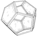
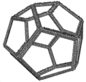
도 1은 본 발명의 예시적인 실시예에 따라, 12면체 형태를 갖는 구조화 요소에 대한 유닛 셀의 사시도.
도 2는 본 발명의 예시적인 실시예에 따라, 복수의 차단된 개구를 갖는 구조화 요소에 대한 유닛 셀의 사시도.
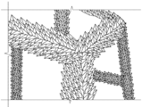
도 3은 본 발명의 예시적인 실시예에 따라, 요철에 의해 거친 표면을 갖는 12 면체 형태를 가지는 구조화 요소에 대한 유닛 셀의 사시도.
도 4는 도 3의 유닛 셀의 확대 사시도.
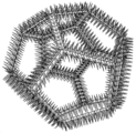
도 5는 본 발명의 예시적인 실시예에 따라, 지주 또는 원 섬유 표면을 갖는 12 면체 형태를 가지는 구조화 요소에 대한 유닛 셀의 사시도.
도 6은 단일체 형상을 갖는 유닛 셀을 가지는 구조화 요소의 사시도.
도 7은 본 발명의 예시적인 실시예에 따라, 단일 셀 및 복수의 차단된 개구를 갖는 유닛 셀을 가지는 구조화 요소의 사시도.
도 8은 본 발명의 예시적인 실시예에 따라, 거친 표면을 갖는 단일체 형상을 갖는 유닛 셀로 구성된 구조화 요소의 사시도.
도 9는 본 발명의 예시적인 실시예에 따라, 스트럿 또는 원 섬유 표면을 갖는 단일체 형상을 갖는 유닛 셀로 구성된 구조화 요소의 사시도.
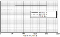
도 10은 본 발명의 예시적인 실시예에 따라, 종래 재료 및 현재 개시된 재료에 대한 여과 능력을 비교한 그래프.
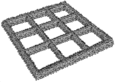
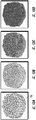
도 11A-D는 다양한 크기의 개구를 갖는 종래의 다공성 여과 매체의 이미지.
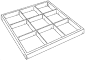
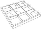
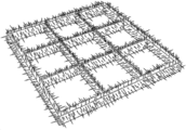
도 12A-D는 본 발명의 예시적인 실시예에 따라, 다양한 크기의 개구를 갖는 본 발명의 구조화 요소의 이미지.
도 13은 도 12A의 구조화 요소의 확대 투시도.1 is a perspective view of a unit cell for a structured element having a dodecahedron shape, according to an exemplary embodiment of the present invention;
Figure 2 is a perspective view of a unit cell for a structured element having a plurality of interrupted openings, in accordance with an exemplary embodiment of the present invention.
3 is a perspective view of a unit cell for a structured element having a dodecahedron shape having a rough surface by unevenness, according to an exemplary embodiment of the present invention.
Figure 4 is an enlarged perspective view of the unit cell of Figure 3;
5 is a perspective view of a unit cell for a structured element having a dodecahedron shape having a strut or fibril surface, in accordance with an exemplary embodiment of the present invention.
6 is a perspective view of a structured element having unit cells having a monolithic shape;
Figure 7 is a perspective view of a structured element having a unit cell with a single cell and a plurality of interrupted openings, in accordance with an exemplary embodiment of the present invention;
8 is a perspective view of a structured element comprised of unit cells having a monolithic shape with a rough surface, in accordance with an exemplary embodiment of the present invention.
9 is a perspective view of a structured element comprised of a unit cell having a monolithic shape with a strut or a fibril surface, in accordance with an exemplary embodiment of the present invention.
Figure 10 is a graph comparing filtration capabilities for conventional materials and presently disclosed materials, in accordance with an exemplary embodiment of the present invention.
11A-D are images of a conventional porous filtration media having openings of various sizes.
Figures 12A-D are images of structured elements of the present invention having apertures of various sizes, in accordance with an exemplary embodiment of the present invention.
Figure 13 is an enlarged perspective view of the structuring element of Figure 12A.
본 발명의 주제가 바람직한 실시예와 관련하여 설명될 것이지만, 그 실시예로 한정하려는 의도는 아니라는 것을 이해할 것이다. 반대로, 첨부된 청구 범위에 의해 정의된 본 발명의 사상 및 범위 내에 포함될 수 있는 모든 대안, 수정 및 등가물을 포함하는 것으로 의도된다.It is to be understood that the subject matter of the present invention will be described in connection with preferred embodiments, but is not intended to be limited to the embodiments. On the contrary, it is intended to cover all alternatives, modifications, and equivalents that may be included within the spirit and scope of the present invention as defined by the appended claims.
본 발명의 주제는 공정 유닛으로 및/또는 공정 유닛 내에서 스트림의 강화 된 처리를 위한 재료 및 방법에 관한 것이다. 유닛에는 일반적으로 장치 내부에 들어가거나 내부에 있는 유동을 조정할 수 있는 내부 구조가 있다. 유닛은 또한 예를 들어, 촉매 반응 및/또는 재료 전달과 같은 원하는 유닛 조작을 수행하기 위한 내부 구조를 갖는다. 스트림 처리 기능은 원하지 않는 종의 유인, 유지 및/또는 완화 및/또는 효과적인 스트림 유동 분배 및 분배를 보장하는 것을 포함할 수 있다. 바람직하지 않은 종은 고체 미립자, 분자 종 및 비말 동반된(entrained) 유체를 제한없이 포함할 수 있다.The subject matter of the present invention relates to materials and methods for the enhanced treatment of streams into process units and / or within process units. The unit usually has an internal structure that can accommodate the flow inside or inside the unit. The unit also has an internal structure for performing desired unit operations, for example, catalytic reaction and / or material transfer. Stream processing functions may include attracting, maintaining and / or mitigating unwanted species and / or ensuring effective stream flow distribution and distribution. Undesirable species may include, without limitation, solid particulates, molecular species, and entrained fluids.
유닛은 유닛 내에 내부 스트림(재순환 스트림과 같은)을공급함으로써 유닛에 진입하는 스트림과 제품으로 유닛을 빠져나가는 스트림을 가질 수 있다. 이들 스트림의 조정은 (i) 바람직하지 않은 종의 완화, (ii) 효과적인 스트림 유동 분할 및 분배의 보장, (iii) 화학 반응 및 성분 분리를 포함하는 재료 전달과 같은 의도하는 유닛 작동 수행 및 (iv) 완성된 제품으로 또는 다른 유닛에 공급함으로써 스트림 발생 및 복구를 비제한적으로 포함하는 다양한 활동을 수반할 수 있다. 이러한 활동은 유닛 내의 이산 구역에서 수행되거나 적절하게 조합될 수 있다.A unit may have a stream entering a unit and a stream exiting the unit into a product by feeding an internal stream (such as a recycle stream) into the unit. Adjustment of these streams may be accomplished by (i) mitigating undesirable species, (ii) ensuring effective stream flow partitioning and distribution, (iii) performing intentional unit operations such as material transfer involving chemical reactions and component separation, and (iv) ) May be accompanied by a variety of activities, including, but not limited to, stream generation and recovery by supplying to the finished product or to other units. These activities may be performed in discrete zones within the unit or may be combined as appropriate.
산업에서 빈번하게 사용되는 간단한 구성의 예로서, 많은 유닛들이 스트림 처리 구역의 상류에 위치된 스트림 처리 구역을 가지며, 이들 모두는 동일한 유닛 내에 포함된다. 이러한 구성 및 산업에서 이용되는 대부분의 구성에서, 처리 구역의 역할은 처리 구역에 유동이 효율적으로 분할 및 분배되고 및/또는 원하지 않는 종이 실질적으로 존재하지 않는 스트림을 처리 구역에 제공하는 것이다. 그러나, 이들 기능의 많은 다른 구성 및 이들 기능의 조합이 유닛내에 설계될 수 있다.As an example of a simple configuration that is frequently used in the industry, many units have stream processing zones located upstream of the stream processing zones, all of which are contained within the same unit. In most configurations used in this configuration and industry, the role of the treatment zone is to provide a stream to the treatment zone where the flow is efficiently split and dispensed and / or a stream of substantially undesirable species is not present. However, many different configurations of these functions and combinations of these functions can be designed in the unit.
일부 경우, 처리 구역은 스트림 유동을 분할하고 분배하는 목적으로 또는 바람직하지 않은 종을 완화시키는 유일한 목적으로 설치될 수 있다. 처리 영역은 이러한 목적을 달성하도록 특별히 고안된 별도의 재료 층으로 구성될 수 있다. 예를 들어, 상이한 형태의 매체(다른 크기 또는 모양 또는 구조 또는 조성물 등을 포함)가 각각의 층이 바람직하지 않은 종의 완화를 목표로 하여 설치될 수 있다. 층은 바람직하지 않은 종을 완화하고 스트림 분할 및 배포를 용이하게 하는 목적을 가진 미디어로 구성될 수 있다. 층은 수행할 기능에 따라 임의의 순서 및 위치에 설치할 수 있다. 유닛은 오직 하나의 처리 구역 또는 각각 하나씩 및 다른 하나의 복수 또는 복수 또는 복수의 조합을 가질 수 있다. 조합은 처리 및 공정 기능을 모두 갖춘 영역을 포함한다.In some cases, the treatment zone may be installed for the purpose of dividing and distributing the stream flow or for the sole purpose of mitigating undesirable species. The processing region may be comprised of a separate material layer specially designed to achieve this purpose. For example, different types of media (including different sizes or shapes or structures or compositions, etc.) may be installed with each layer aimed at mitigating undesirable species. The layer may consist of media having the purpose of mitigating undesirable species and facilitating stream partitioning and distribution. Layers can be installed in any order and position depending on the function to be performed. A unit may have only one processing zone or one each and a plurality, a plurality, or a combination of a plurality of the other. The combination includes areas having both processing and processing functions.
처리 구역은 바람직하지 않은 종을 유치, 보유 및/또는 달리 완화시키는 능력 및/또는 이들을 통과하는 스트림의 유동을 효율적으로 분할 및 분배하는 능력에 의해 1차적으로 지시된 유용한 수명을 가질 수 있다. 처리 구역은 시간이 지남에 따라 막히거나 막히게 되어, 결국 원하지 않는 종을 유치, 유지 및 완화하고 및/또는 스트림의 유동을 분할하고 분배하는 능력이 저하될 수 있다. 이러한 처리 능력의 저하에 따라, 불충분하게 처리된 스트림은 하류 영역으로 진행할 수 있다. 처리 구역의 상태가 나빠짐은 유닛 자체의 압력 강하를 증가시킬 수 있으며, 이는 처리 구역의 내용물 및 대개 하류 구역의 내용물을 재생(예를 들어, 재생 또는 부분적 또는 완전 교체를 통해)시키기 위해 유닛 셧다운을 필요로 할 수 있다.The treatment zone may have a useful lifetime primarily indicated by the ability to attract, retain and / or otherwise mitigate undesirable species and / or by the ability to efficiently partition and distribute the flow of the stream through them. The treatment zone may become clogged or clogged over time, eventually degrading the ability to attract, maintain and mitigate undesired species and / or divide and distribute the flow of the stream. With this degradation of the processing capability, the insufficiently treated stream can proceed to the downstream region. A poor condition of the treatment zone may increase the pressure drop of the unit itself, which may cause unit shutdown to regenerate the contents of the treatment zone and usually the contents of the downstream zone (e.g., through regeneration or partial or complete replacement) You may need it.
처리 구역의 기능은 처리 구역을 빠져나가는 적절하게 맞춤화된 스트림을 처리하는 것이다. 이러한 공정의 예는 (i) 열, 압력 및/또는 촉매 수단을 통한 분자 전환 및 (ii) 증류, 추출 등을 통한 성분 분리를 포함한다. 이러한 가공 구역에서 사용되는 일부 재료 및 매체는 유용한 "온-오일" 수명을 가질 수 있다. 예를 들어, 처리 영역 내의 매질이 촉매인 공정 유닛에서, 촉매 매질의 성능은 촉매 종의 막힘 또는 응집 또는 전환에 의해 야기된 촉매 불활성화로 인해 시간이 지남에 따라 저하될 수 있다. 처리 구역 촉매 비활성화에 대한 전형적인 응답은 촉매 성능을 유지하기 위해 유닛 온도를 증가시키는 것이다. 최대 허용 온도에 도달하면 유닛 셧다운이 요구된다. 개선된 처리 구역은 [i] 더 분산되어 분배된 유동을 제공함으로써 촉매 수명을 연장하고, [ii] 원하지 않는 종의 농도가 감소된 농도를 포함하는 스트림 유동을 제공함으로써 촉매 수명을 연장하고, 및 [iii] 보다 유리하게 보다 생산적인 촉매 매체, 즉, 보다 활성인 매체 또는 보다 오래 지속되는 매체의 사용을 허용함으로서 촉매 공정 구역의 성능강화를 용이하게 한다.The function of the processing zone is to process appropriately customized streams exiting the processing zone. Examples of such processes include (i) molecular separation via heat, pressure, and / or catalytic means and (ii) separation of components through distillation, extraction, and the like. Some materials and media used in such processing zones may have useful "on-oil" lifetimes. For example, in a process unit where the medium in the treatment zone is a catalyst, the performance of the catalyst medium may degrade over time due to catalyst deactivation caused by clogging or flocculation or conversion of the catalyst species. A typical response to treatment zone catalyst deactivation is to increase the unit temperature to maintain catalyst performance. When the maximum allowable temperature is reached, a unit shutdown is required. The improved treatment zone extends the catalyst life by providing [i] a more dispersed and distributed flow to prolong the catalyst lifetime, [ii] extend the catalyst lifetime by providing a stream flow comprising a reduced concentration of undesired species, and [iii] facilitates enhancing the performance of the catalytic processing zone by allowing the use of more advantageously more productive catalyst media, i.e., more active or longer lasting media.
처리 영역을 통과하는 스트림에서 바람직하지 않은 종을 끌어당기고, 유지하고 및/또는 완화시키는 다양한 종래의 수단이 존재한다. 예를 들어, 흡수제 또는 다른 활성 재료는 이들을 유출물 스트림의 내의 유닛으로부터 분출되거나 종래의 여과 솔루션을 사용하여 효과적으로 제거될 수 있는 더 큰 미립자 재료로 변환될 수 있도록 원하지 않는 화학 종을 불활성으로 만드는데 사용될 수 있다. 황화철 등과 같은 반응 생성물을 포함하는 원하지 않는 화학 종은 작은 미립자를 형성할 수 있다. 기존 여과 기술은 제거할 수 있는 미립자 크기에 대해 제한이 있어 원하지 않는 화학 종을 처리할 수 있는 능력이 제한된다.There are a variety of conventional means for attracting, retaining and / or mitigating undesirable species in the stream passing through the treatment area. For example, sorbents or other active materials may be used to inactivate undesirable species so that they can be ejected from a unit within the effluent stream or converted to a larger particulate material that can be effectively removed using conventional filtration solutions . Undesirable chemical species, including reaction products such as iron sulfide, may form small particulates. Conventional filtration techniques have limited particle size that can be removed, limiting their ability to handle unwanted chemical species.
종래의 여과 매체는 또한 유닛 내의 구역을 처리하는 데 사용된다. 그러나 이러한 매체가 막히거나 차단되면 필터 시스템과 장치 자체의 압력 강하가 증가하여 사용된 필터 매체 및 시스템을 제거하고 교체하기 위해 전체 장치를 오프라인으로 전환해야 할 수 있다.Conventional filtration media are also used to treat zones within a unit. However, when these media are clogged or blocked, the pressure drop of the filter system and the device itself may increase, requiring the entire device to be taken offline to remove and replace the filter media and systems used.
필터 시스템 역 세척이 또한 여과된 미립자를 제거하는데 사용된 바 있다. 이러한 교환 및/또는 세척은 장치 가동 중단 시간, 필터 시스템 비용 및 유지 보수 노력으로 인해 비용이 수반되는 비용이 많이 드는 중단을 필요로 한다. 이러한 교체 및/또는 세척은 또한 장치 종료, 시동 및 유지 보수와 관련된 운영 위험을 초래한다.Filter system backwashing has also been used to remove filtered particulates. Such swapping and / or flushing requires costly breaks that are accompanied by cost due to device downtime, filter system cost and maintenance effort. Such replacement and / or cleaning also results in operational hazards associated with device termination, start-up and maintenance.
다공성 여과 매체는 스트림에서 발견되는 원하지 않는 종을 끌어당기고 유지하는데 사용되어 왔다. 통상적인 다공성 여과 매체는 전형적으로 산업 유닛에서의 심각한 작동 조건을 견딜 수 있는 세라믹 또는 금속으로 구성된다. 이러한 매질의 1 차 여과 메카니즘은 매질의 공극 내에서 발생하는 것으로 생각되어왔다. 이러한 종을 효과적으로 완화시키는 이러한 매질의 능력은 지금까지는 일반적으로 "ppi"또는 "인치 당 공극"으 측정된 공극 크기 분배와 상관 관계가 있다. 통상적인 다공성 여과 매체는 약 10 내지 100 범위의 ppi로 상업적으로 제조될 수 있다. 상기 매체의 바람직하지 않은 종을 끌어당기고 보유하는 능력은 ppi뿐만 아니라 매체의 내부 표면 영역에 의존한다. 예를 들어, 10ppi의 통상적인 다공성 매체는 1 입방 미터의 매체 당 약 300 평방 미터의 내부 표면 영역을 가지며, 약 650 내지 2000 미크론 크기의 원하지 않는 종을 끌어당겨 보유할 수 있다. 100 ppi의 통상적인 다공성 매체는 1 입방 미터의 매체 당 약 2400 평방 미터의 내부 표면 영역을 가지며, 약 40 내지 500 미크론 크기의 바람직하지 않은 종을 끌어당겨 보유할 수 있다. 40 미크론 이하의 크기를 가진 원하지 않는 종들에 대한 완화는 상업적으로 불가능하다. 또한 크기가 예를 들어 40~2000 미크론인 원하지 않는 화학 종을 완화하려면 여러 가지 재래종 매체를 사용해야 하며 각각 자체 ppi 구조 및 관련 내부 표면 영역이 필요하다. 가능한 최대치(10ppi 매체에 대해 2000 미크론, 100ppi 매체에 대해 500 미크론)를 초과하는 종을 완화하려는 시도는 기존 매체의 성능 저하를 초래한다.Porous filtration media have been used to attract and retain unwanted species found in streams. Typical porous filtration media typically consist of a ceramic or metal capable of withstanding severe operating conditions in an industrial unit. The primary filtration mechanism of this medium has been thought to occur within the pores of the medium. The ability of this medium to effectively mitigate these species has so far been correlated to the measured pore size distribution, generally measured as "ppi" or "voids per inch. &Quot; Conventional porous filtration media can be commercially prepared with ppi ranging from about 10 to 100. The ability to attract and hold undesirable species of the medium depends not only on the ppi but also on the inner surface area of the medium. For example, a typical 10 ppi porous media has an inner surface area of about 300 square meters per cubic meter of medium, and can hold an unwanted species of about 650 to 2000 microns in size. A typical porous medium of 100 ppi has an inner surface area of about 2400 square meters per cubic meter of medium and can hold an undesirable species of about 40 to 500 microns in size. Mitigating unwanted species with sizes of less than 40 microns is commercially impractical. In addition, to alleviate unwanted chemical species, for example 40 to 2000 microns in size, several native media must be used, each with its own ppi structure and associated inner surface area. Attempts to mitigate species that exceed the maximum possible (2000 microns for 10 ppi media and 500 microns for 100 ppi media) result in performance degradation of existing media.
다공성 매체는 동일 유닛의 하류 공정 영역으로의 유동 분할 및 분배를 달성하기 위해 유닛의 처리 구역에 자주 사용된다. 상기 목적에 관한 일반적인 개념은 처리 영역 유동 분할 및 분배가 감소된 공극 크기가 증가된 분할 및 분배 능력을 증가시킴에 따라 향상된다는 것이다. 상술한 바에 따라 처리 구역 매체의 접촉 표면 영역의 양 및 구조가 바람직하지 않은 종 완화뿐만 아니라 스트림 유동 분할 및 분배의 효능을 결정한다는 것을 입증한다.Porous media is often used in processing zones of the unit to achieve flow partitioning and distribution to downstream process areas of the same unit. The general concept of this objective is that the treatment region flow partitioning and distribution is improved as the reduced pore size increases the increased partitioning and dispensing capacity. Demonstrates that the amount and structure of the contact surface area of the treatment zone medium as determined above determines the efficacy of stream flow partitioning and distribution as well as undesirable longitudinal relaxation.
최적의 스트림 처리 시스템을 제공하기 위해서는 이러한 시스템의 적절한 선택, 설계, 제조, 설치, 작동 및 유지 보수가 필요하다. 고려해야 할 핵심 성능 매개 변수에는 원하지 않는 화학 종을 유치, 보유 및/또는 달리 완화하기 위해 선택된 재료의 견고성 및/또는 효과적인 재료 분배 및 분배를 제공하기 위한 그러한 재료의 구성 및 조립이 포함된다.The proper selection, design, manufacture, installation, operation and maintenance of such a system is required to provide an optimal stream processing system. Key performance parameters to consider include construction and assembly of such materials to provide robustness and / or effective material distribution and distribution of selected materials to attract, retain and / or otherwise alleviate unwanted species.
처리 구역은 상기 처리 구역과 동일한 유닛 내에 또는 처리 구역을 포함하는 용기의 하류에 위치할 수 있다. 유닛 내의 구역은 스트림을 처리 및/또는 프로세싱하는 데 사용된다. 일부 지역에서는 스트림을 동시에 처리하고 프로세싱한다. 보다 일반적으로, 처리 구역을 통과하는 스트림은 후속적으로 처리 구역으로 통과된다.The treatment zone may be located in the same unit as the treatment zone or downstream of the vessel containing the treatment zone. The zones in the unit are used to process and / or process the stream. In some areas, streams are processed and processed simultaneously. More generally, the stream passing through the treatment zone is subsequently passed to the treatment zone.
특정 예시적인 실시예에서, 본 발명은 스트림을 동시에 처리하고 프로세싱하는 구역에서 또는 독립형 처리 구역에서 사용될 수 있다. 구체적으로, 본 발명은: (i) 바람직하지 않은 종을 유치, 유지 및/또는 달리 완화시키기 위한 유닛 내부의 능력을 보다 충분히 활용; (ii) 스트림을 유닛 내에서 처리 구역으로 보다 효과적으로 분할하고 분배; (iii) 상기 처리 구역 해결책의 비용을 줄이면서 동시에 상기 유닛의 처리 구역의 능력을 최대한 활용할 수 있게 하고; 및 (iv) 유닛 수익성이 실질적으로 증가할 수 있도록 한다.In certain exemplary embodiments, the present invention may be used in a zone that processes and processes streams simultaneously or in a stand-alone processing zone. Specifically, the present invention provides: (i) fully exploiting the capabilities within the unit to attract, maintain and / or otherwise alleviate undesirable species; (ii) more effectively divide and distribute the stream into processing zones within the unit; (iii) to maximize the capabilities of the processing zone of the unit while reducing the cost of the processing zone solution; And (iv) substantially increase unit profitability.
특정 예시적인 실시예에서, 본원에 공개된 주제는 통상적으로 입수 가능한 재료의 것보다 높은 원하지 않는 종의 스트림 유동 분할 및 분배 및 저감 능력을 갖는 구조화 요소를 포함한다. 유닛에 사용되는 경우, 본원에 기재된 구조화 요소는 종래 기술의 재료와 비교할 때 다수의 장점을 갖는다. 유닛 내의 구역을 처리 구역을 위해, 상기 장점은: (i) 요구되는 처리 구역의 깊이 감소, (ii) 선행 기술 재료에 의해 처리될 수 없는 바람직하지 않은 종을 끌어 당기고, 보유하고 및/또는 달리 완화, 및 (iii) 선행 기술 재료보다 효율적으로 처리 구역으로 유동 분할 및 분배를 제공을 포함한다. 처리 구역에 있어서, 상기 장점은: (i) 처리 구역으로부터 배출되는 보다 깨끗하고 더 잘 분할 및/또는 분배된 스트림의 장점을 갖는 것, (ii) 보다 효과적인 촉매 구역 유형 또는 형태와 같은 보다 효과적인 처리 구역 내부의 이용을 허용, 및 (iii) 촉매, 흡착제 또는 다른 내부의 로딩을 증가시키기 위한 추가적인 공정 구역 공간을 생성하는 것을 포함한다. 전체적으로 유닛에 대해 상기 장점은: (i) 가동 중단 시간을 포함하여 유닛 생산성 저하, (ii) 그러한 중단과 관련된 운영 위험 감소, (iii) 유닛 안정성 및 수익성 증대를 포함한다.In certain exemplary embodiments, the subject matter disclosed herein includes structuring elements having stream flow partitioning and distribution and abatement capabilities that are higher than those of materials typically available. When used in a unit, the structuring elements described herein have a number of advantages when compared to materials of the prior art. For zones within the unit, the advantages are: (i) a reduction in the depth of the processing zone required; (ii) pulling, holding and / or otherwise bringing undesirable species that can not be treated by prior art materials; And (iii) providing flow partitioning and dispensing to the treatment area more efficiently than prior art materials. In the treatment zone, the advantages are: (i) the benefit of a cleaner, better split and / or dispensed stream exiting the treatment zone, (ii) more effective treatment such as a more effective catalytic zone type or morphology Permitting utilization within the zone, and (iii) creating additional process zone space to increase loading of the catalyst, adsorbent or other interior. Overall, these advantages for a unit include: (i) reduced unit productivity including downtime, (ii) reduced operational risk associated with such outages, and (iii) increased unit stability and profitability.
다공성 매체를 사용하는 처리 구역에서의 통상적인 여과 시스템은 여과 매체의 공극 내에 여과가 발생하는 것으로 여겨지는 기공 중심적이다. 최근의 연구에 따르면 이러한 매질에서의 1차 여과 메카니즘은 매질 내의 접촉 표면상의 원하지 않는 종의 인력, 유지 및/또는 완화 작용이라는 것이 밝혀졌다. 특정 예시적인 실시예에서, 본 발명의 주제는 통상적인 필터 매질에서 발견되는 것보다 우수한 접촉 표면 구조를 갖는 구조화 요소를 포함한다. 접촉 표면 구조는 원하지 않는 종을 유치, 유지 및/또는 완화시키고 및/또는 스트림의 유동 분할 및 분배를 보다 용이하게 한다.Conventional filtration systems in processing zones using porous media are pore-centric, which is believed to occur within the pores of the filtration media. Recent studies have shown that the primary filtration mechanism in this medium is the attraction, maintenance and / or mitigation of unwanted species on the contact surface in the medium. In certain exemplary embodiments, the subject matter of the present invention includes structured elements having a contact surface structure that is superior to that found in conventional filter media. The contact surface structure facilitates attracting, maintaining and / or mitigating unwanted species and / or facilitating flow partitioning and distribution of the stream.
특정 예시적인 실시예에서, 구조화 요소는 종래의 재료 아키텍처에 비해 상당히 증가된 접촉 표면 영역을 갖는 다면적 3차원 기하학적 구조를 갖는다. 구조화 요소는 상호 연결된 유닛 셀을 포함할 수 있으며, 각각의 유닛 셀은 프레임 및 복수의 면을 갖는다. 개별 면은 열리거나 부분적으로 열리거나 닫힐 수 있다. 유닛 셀면의 총 면적의 최소 10%는 닫힐 수 있다. 구조화 요소는 유닛 셀 상에 형성된 복수의 돌기를 추가로 포함할 수 있다. 돌기는 채널, 플루트, 스파이크, 피브릴 및 필라멘트 중 하나 이상을 포함할 수 있다. 구조화 요소는 상호 연결된 유닛 셀의 면에 있는 개구를 통해 구조체를 관통하는 복수의 사형 통로를 가질 수 있다.In certain exemplary embodiments, the structured element has a multi-faceted three-dimensional geometry with significantly increased contact surface area compared to conventional material architectures. The structuring element may comprise interconnected unit cells, each unit cell having a frame and a plurality of faces. Individual faces can be opened or partially opened or closed. At least 10% of the total area of the unit cell surface can be closed. The structuring element may further comprise a plurality of protrusions formed on the unit cell. The protrusions may include one or more of channels, flutes, spikes, fibrils and filaments. The structuring element may have a plurality of threaded passages through the structure through openings in the face of the interconnected unit cells.
구조화 요소 유닛 셀의 대표적인 3차원 구조는 규칙적 및 불규칙한 다면체 및 단일체를 포함할 수 있다.Representative three-dimensional structures of structured element unit cells may include regular and irregular polyhedra and monoliths.
구조화 요소의 접촉면은 그 사형 통로 및 유닛 셀의 프레임, 면 및 돌기를 포함하는 유닛 셀 모두의 표면을 포함할 수 있다. 본 발명의 재료의 접촉 표면은 종래 기술 재료의 접촉 표면을 능가한다.The contact surface of the structuring element may comprise the surfaces of both the mold passage and the unit cells including the frame, the face and the projection of the unit cell. The contact surface of the material of the present invention surpasses the contact surface of prior art materials.
이러한 접촉 표면은 인력, 보유력, 부착력, 흡수성, 유착, 응집, 모세관 작용 등을 통해 원하지 않는 종을 완화시키는 주요 수단을 제공한다. 이로 인해 처리 구역 내의 원하지 않는 종의 완화가 증가하여 유닛 성능이 향상된다.Such contact surfaces provide a key means of mitigating unwanted species through attraction, retention, adhesion, absorbency, adhesion, aggregation, capillary action, and the like. This increases the relaxation of unwanted species in the processing zone and improves unit performance.
특정 예시적인 실시예에서, 구조화 요소는 미립자 및 분자 종을 끌어당기고, 유지하고 및/또는 완화시키는 재료의 능력을 향상시키는 사형(tortuosity) 및 경계층 상태를 갖는다. 예를 들어, 특정 예시적인 실시예에서, 본원에 개시된 재료는 200 나노 미터만큼 작은 크기, 특정 실시 예에서는 100 나노 미터 크기의 종을 끌어 당겨 보유할 수 있다.In certain exemplary embodiments, the structuring element has a tortuosity and boundary layer condition that enhances the ability of the material to attract, retain, and / or mitigate the particulate and molecular species. For example, in certain exemplary embodiments, the materials disclosed herein may be pulled by a size of as small as 200 nanometers, and in certain embodiments by a size of 100 nanometers.
특정 예시적인 실시예에서, 구조화 요소는 종래의 다공성 매질을 형성하는데 사용되는 발포체, 겔 및 돌출부의 자연 형성에 의해 설정된 기하학적 경계를 넘어 구조적 특성을 갖도록 조작될 수 있다. 구조화 요소는 끌어당김, 유지 및/또는 기타 완화 기능을 개선하고 유동 분할 및 배포를 향상시키는 "활성" 표면 기능을 가질 수 있다.In certain exemplary embodiments, the structuring element may be manipulated to have structural properties beyond the geometric boundaries established by the natural formation of the foam, gel, and protrusions used to form the conventional porous media. Structured elements can have "active" surface features that improve pull, hold and / or other relaxation functions and improve flow partitioning and distribution.
예를 들어, 특정 예시적인 실시예에서, 활성 표면 특징은: (i) 유닛 셀면의 가공된 막힘 또는 부분 차단; (ii) 표면의 거칠기와 채널, 플루트, 스파이크, 피브릴, 필라멘트 등과 같은 설계된 표면 거칠기 또는 불규칙성을 고려하여 설계; (iii) 사형 표면 및 통로의 표면 영역 증가; (iv) 액체의 풀링(pooling) 및 정착을 허용하는 영역; 및 (v) 반데르 발스 접착력이 확대되는 증가된 층류 및 경계층 구역을 포함한다.For example, in certain exemplary embodiments, the active surface features may include: (i) processed clogs or partial block of the unit cell surface; (ii) design of the surface roughness and designed surface roughness or irregularities such as channels, flutes, spikes, fibrils, filaments, etc.; (iii) increasing the surface area of the sandblasted surface and passageways; (iv) an area that allows pooling and settlement of the liquid; And (v) increased laminar flow and boundary layer zones where Van der Waals adhesion is increased.
풀링(pooling) 및 정착 영역의 활성 표면 특징은 스톡스 법칙에 따라 큰 입자보다 더 많은 시간을 풀링 및 정착을 필요로 하는 작은 입자의 강화된 포획을 포함한다.The active surface features of the pooling and fusing areas include enhanced capture of small particles that require pooling and settlement in more time than larger particles according to Stokes law.
또한, 매우 작은 입자(즉, 250 미크론 이하)의 수집에 대해 반데르발스 접착력이 지배적으로 나타나는 것이 알려져 있다. 반데르발스 접착력은 표면 형태에 따라 달라지며, 입자 또는 입자와 벽 사이의 접촉 면적이 더 커지는 표면 거칠기 또는 돌출부가 있으면 반데르발스의 인력 및 기계적 인터로킹 경향이 증가한다.It is also known that van der Waals adhesion predominates over the collection of very small particles (i.e., 250 microns or less). The van der Waals adhesion depends on the surface morphology and the surface roughness or protrusion of the larger contact area between the particles or the particles and the wall increases the van der Waals attraction and mechanical interlocking tendency.
특정 예시적인 실시예에서, 구조화 요소는 개선된 표면 구조 및 조건으로 인해 현존하는 다공성 또는 셀성 재료 이상으로 향상된 성능을 이끌어내는 설계된 구조를 갖는다. 구조화 요소는 분자 흡착 및 보유 플러스 반데르발스 접착력이 확대되는 박막 경계층을 함유하는 확대된 접촉 표면 영역을 가질 수 있다.In certain exemplary embodiments, the structured element has a designed structure that leads to improved performance over existing porous or cellular materials due to improved surface structure and conditions. The structured element may have an enlarged contact surface area containing a thin film boundary layer with increased molecular adsorption and retention plus van der Waals adhesion.
특정 예시적인 실시 예에서, 구조화 요소의 표면 특성은 바람직하지 않은 종의 완화를 향상시키는 재료로 전체적으로 또는 부분적으로 구성되거나 커버된 표면을 포함할 수 있다. 도시된 예는 비소 및 바나듐과 같은 금속 분자 종을 끌어당기고 유지하는 데 도움이 되는 재료를 가진 세척 코팅이며, 둘 다 강력한 촉매 탈활성화제 또는 독물이다.In certain exemplary embodiments, the surface properties of the structured element may comprise surfaces that are wholly or partially constructed or covered with a material that enhances the relaxation of undesirable species. Illustrative examples are cleaning coatings with materials that help attract and retain metal molecular species such as arsenic and vanadium, both being powerful catalytic deactivators or poisons.
구조화 요소는 바람직하지 않은 종의 표면 인력, 유지 및 유착을 위한 증가 된 기회를 제공한다. 특정 예시적인 실시예에서, 구조화 요소의 기능적 접촉 표면은: (i) 셀의 면, (ii) 셀을 연결하는 스트럿의 표면, (iii) 스트럿을 연결하는 노드의 표면 및 iv) 상기 모든 표면 또는 표면의 채널, 플루트, 스파이크, 피브릴 또는 필라멘트에 의해 야기된 요철 또는 요철의 표면중의 하나를 포함할 수 있다. 구조화 요소의 기능적 접촉 표면은 유착, 화학 반응, 큰 종으로의 원자 응집, 공정 유닛의 추출, 흡착 등을 향상시키도록 제조 또는 변형될 수 있다.The structuring element provides an increased opportunity for surface attraction, retention and adhesion of undesirable species. In a particular exemplary embodiment, the functional contact surface of the structuring element comprises: (i) the face of the cell, (ii) the surface of the strut connecting the cell, (iii) the surface of the node connecting the strut, and (iv) A surface channel, a flute, a spike, a fibril, or a surface of irregularities or irregularities caused by filaments. The functional contact surface of the structured element can be made or modified to improve adhesion, chemical reaction, atomic cohesion into large species, extraction of process units, adsorption, and the like.
특정 예시적인 실시예에서, 구조화 요소는 유닛의 유동 분할 및 분배를 용이하게 할 수 있다. 유동 분할 및 분배 향상은 사형 혼합뿐만 아니라 특정 실시예에서는 구조화 요소의 표면상의 박막의 개발에 기인할 수 있다는 것을 알게 되었다. 이러한 필름 및 표면은 분할 및 유동 분배를 위한 비히클을 제공할 수 있다. 따라서, 유동 분할 및 분배 성능의 초점은 기공 크기 및 기공 체적으로부터 접촉 표면, 표면 영역 및 표면 요철 및 불규칙성으로 전환된다.In certain exemplary embodiments, the structuring element may facilitate flow partitioning and distribution of the unit. It has been found that flow partitioning and distribution enhancement can be attributed not only to sand blending but also to the development of thin films on the surface of structured elements in certain embodiments. Such films and surfaces may provide a vehicle for partitioning and flow distribution. Thus, the focus of flow partitioning and distribution performance is shifted from pore size and pore volume to contact surfaces, surface areas, and surface irregularities and irregularities.
특정 예시적인 실시예에서, 구조화 요소는 통상적인 재료보다 넓은 범위의 원하지 않는 종을 끌어당기고 유지 및/또는 달리 완화시키는 적절하게 조작된 구조를 가질 수 있다. 이것은 유닛의 처리 영역에서 매체 "등급" (및 이를 포함하는 데 필요한 공간)의 층 수를 줄이고 유닛의 처리 구역의 추가된 유닛 내부(예: 촉매)를 위한 가치있는 공간을 제거하는 중요한 경제적 장점을 제공한다. 특정 예시적인 실시예에서, 구조화 요소는 60% 이상의 내부 보이드 분율을 갖는 재료를 포함한다. 특정 예시적인 실시예에서, 구조화 요소는 0.5 내지 50 밀리미터 크기의 셀로 시작될 수 있다.In certain exemplary embodiments, the structuring element may have a suitably engineered structure that attracts, retains, and / or otherwise alleviates a wider range of undesirable species than conventional materials. This has the significant economic advantage of reducing the number of layers of the medium "grade" (and the space required to contain it) in the processing zone of the unit and eliminating valuable space for additional units inside the unit's processing zone to provide. In certain exemplary embodiments, the structuring element comprises a material having an internal void fraction of 60% or greater. In certain exemplary embodiments, the structuring element may be initiated with cells ranging from 0.5 to 50 millimeters in size.
특정 예시적인 실시예에서, 구조화 요소는 다면체 형상 재료를 포함할 수 있다. 다면체 형상은 예를 들어, 사면체, 입방체, 팔면체, 십면체 및 십이면체를 포함할 수 있다. 다면체 형상은 결합 구조체를 형성하도록 함께 위치되는 다각형 형상 재료를 포함하는 복수의 상호 연결된 유닛 셀로부터 형성될 수 있다. 또한, 구조화 요소는 망상 세라믹뿐만 아니라 모놀리식 구조를 포함하는 임의의 다른 셀룰러 세라믹을 포함할 수 있다.In certain exemplary embodiments, the structuring element may comprise a polyhedral material. The polyhedral shape may include, for example, a tetrahedron, a cube, an octahedron, an octahedron, and a dodecahedron. The polyhedral shape may be formed from a plurality of interconnected unit cells comprising polygonal shaped materials that are positioned together to form a bonded structure. In addition, the structuring element may comprise not only network ceramic, but also any other cellular ceramic including a monolithic structure.
구조화 요소 유닛 셀의 다양한 예시적인 실시예가 도 1-5에 도시되어 있다. 도 1은 표준 12면체 모양의 유닛 셀을 보여 주며, 예를 들어 망상 세라믹용 빌딩 블록일 수 있다. 도 2는 대략 50% 차단 된 개구를 갖는 12면체 형태의 유닛 셀을 도시한다. 도 3은 거친 표면의 12면체 형상의 유닛 셀을 도시한다. 도 4는 거친 표면을 추가로 도시하는 도 3의 12면체 형상 유닛 셀의 확대도이다. 도 5는 피브릴 표면을 갖는 12면체 형태의 유닛 셀을 도시한다. 도 12A-12D는 유닛 셀이 상이한 크기(1 인치당 공극으로 측정)를 갖는 복수의 유닛 셀로 구성된 구조화 요소의 대표도이다. 도 12A의 확대 부분인 도 12E는 특정 예시적인 실시예에서 종래의 재료에 비해 접촉 표면 영역을 현저히 증가시키는 구조화 요소의 표면 특성을 도시한다. 도 6은 표준 모놀리 식 구조를 갖는 구조화 요소를 도시한다. 도 7은 약 50% 차단 된 개구를 갖는 모놀리식 구조를 도시한다. 도 8은 거친 표면을 갖는 모놀리식 구조를 도시한다. 도 9는 스파이크 또는 피브릴 표면을 갖는 모놀리식 구조를 도시한다.Various exemplary embodiments of structured element unit cells are shown in Figs. 1-5. Figure 1 shows a unit cell in the form of a standard dodecahedron, for example a building block for a network ceramic. Figure 2 shows a unit cell in the form of a dodecahedron with approximately 50% blocked openings. Fig. 3 shows a unit cell in the form of a dodecahedron having a rough surface. Figure 4 is an enlarged view of the dodecahedral unit cell of Figure 3 further showing a rough surface. Figure 5 shows a unit cell in the form of a dodecahedron having a fibril surface. Figures 12A-12D are representative views of structured elements comprising a plurality of unit cells having different sizes (measured as voids per inch). 12E, which is an enlarged portion of FIG. 12A, illustrates surface characteristics of a structured element that significantly increase the contact surface area compared to conventional materials in certain exemplary embodiments. Figure 6 shows a structuring element having a standard monolithic structure. Figure 7 shows a monolithic structure with about 50% blocked openings. Figure 8 shows a monolithic structure with a rough surface. Figure 9 shows a monolithic structure with a spike or fibril surface.
특정 예시적인 실시예에서, 구조화 요소는 상기 구조화 요소의 입방 미터 당 200 내지 800,000 평방 미터 범위의 기하학적 접촉 표면 영역을 갖는 재료를 포함한다. 특정 양태에서, 구조화 요소들은 구조화 요소들의 입방 미터 당 적어도 10,000 평방 미터의 표면 영역을 갖는 접촉 표면을 가질 수 있다. 구조화 요소는 또한 구조 요소의 입방 미터 당 최대 800,000 평방 미터의 표면 영역을 가진 접촉 표면을 가질 수 있다. 구조화 요소는 또한 1 평방 미터 당 10,000 내지 800,000 평방 미터의 표면 영역을 갖는 접촉 표면을 가질 수 있다.In certain exemplary embodiments, the structuring element comprises a material having a geometric contact surface area in the range of 200 to 800,000 square meters per cubic meter of the structured element. In certain embodiments, the structuring elements may have a contact surface with a surface area of at least 10,000 square meters per cubic meter of structuring elements. The structuring element may also have a contact surface with a surface area of up to 800,000 square meters per cubic meter of structural element. The structuring element may also have a contact surface with a surface area of 10,000 to 800,000 square meters per square meter.
특정 예시적인 실시예에서, 본원에 기술된 대상물의 구조화 요소의 접촉 표면 영역 범위는 종래 기술 재료의 접촉 표면 영역 범위보다 상당히 크다. 또한 특정 등급의 구조화 요소는 원하지 않는 종을 유치하고 유지할 수 있는 범위가 훨씬 넓다. 예를 들어, 10 ppi의 기존 매체에 해당하는 구조화 요소는 20 내지 2000 미크론 범위의 종의 흡착 및 보유 및 100ppi에 상응하는 구조화 성분은 0.1 내지 500 미크론 범위의 종을 흡착 및 보유할 수 있다.In certain exemplary embodiments, the contact surface area range of the structured element of the objects described herein is significantly larger than the contact surface area range of prior art materials. Certain classes of structuring elements also have a much wider range of possibilities to attract and retain unwanted species. For example, a structuring element corresponding to a conventional medium of 10 ppi may adsorb and retain species of species ranging from 0.1 to 500 microns, with the adsorption and retention of species in the range of 20 to 2000 microns and the corresponding structuring component of 100 ppi.
종래의 재료 및 현재 개시된 재료에 대한 여과 능력의 그래프 비교가 도 10에 도시된다. 그래프는 종래 기술의 재료(예를 들어, 본 명세서의 파라그래프 28에 기술된 바와 같이) 및 현재 개시된 재료 입자 크기는 x 축상에 미크론 유닛으로 표시된다. 표준 구조 A 라인은 종래 기술의 10ppm 매체의 여과 능력에 대응한다. 이 매체는 입자 크기를 650~2000 미크론으로 필터링할 수 있다. 표준 구조 B 라인은 종래 기술의 100ppm 매질의 여과 능력에 대응한다. 이 매체는 입자 크기를 40~500 미크론으로 필터링할 수 있다. 상기 두 가지는 상업적으로 제조되고 사용될 수 있은 기존 재료의 상한 및 하한 ppi 한계를 나타낸다. 도 10에 도시된 바와 같이, B 라인(500 미크론)의 상단과 A 라인(650 미크론)의 하단 사이에는 갭이 존재한다. 40~2000 미크론 범위 전체에서 미립자를 걸러 내야하는 특정 공정 적용예의 경우 A 및 B 구조와 500~650 미크론 간격을 연결하는 다른 구조(약 50ppi)가 필요하다. 이것은 유닛의 세 가지 다른 층에 있는 매체의 세 가지 등급이 활용되어야 함을 의미한다.A graphical comparison of filtration capabilities for conventional materials and presently disclosed materials is shown in FIG. The graphs show the materials of the prior art (e.g., as described in paragraph 28 of this disclosure) and the material particle sizes currently disclosed as micron units on the x-axis. The standard structure A line corresponds to the filtration capability of the prior art 10 ppm media. The media can be filtered to a particle size of 650 to 2000 microns. The standard structure B line corresponds to the filtering capacity of the prior art 100 ppm medium. The media can be sized to a particle size of 40 to 500 microns. Both of these represent the upper and lower ppi limits of conventional materials that can be manufactured and used commercially. As shown in FIG. 10, there is a gap between the top of the B line (500 microns) and the bottom of the A line (650 microns). For certain process applications where particulate should be sieved throughout the 40-2000 micron range, there is a need for A and B structures and other structures (about 50 ppi) that connect 500 to 650 micron spacing. This means that three classes of media in three different layers of the unit should be utilized.
이와 비교하여, 도 10의 구조화 요소 라인은 소정의 예시적인 실시예에서 현재 개시된 재료 중 단지 하나의 등급의 성능을 나타낸다. 상기 등급은 단독으로 사용될 때 20~2000 미크론 크기의 미립자를 걸러낼 수 있으므로 표준 구조 A 라인과 표준 구조 B 라인의 전체 범위에 해당한다. 따라서, 전술한 바와 같이, 구조화 요소는 종래 기술의 매체로 실현 가능한 것보다 작거나 더 큰 미립자를 여과할 수 있다. 예를 들어, 구조적 요소는 소정의 예시적인 실시 예에서 0.1 미크론 (100 나노 미터)의 작은 미립자 및 11 밀리미터 만큼 큰 미립자를 걸러 낼 수 있다.In comparison, the structured element line of FIG. 10 represents the performance of only one of the materials presently disclosed in some exemplary embodiments. This grade, when used alone, can filter out particulates of 20 to 2000 microns in size, thus covering the full range of standard structure A line and standard structure B line. Thus, as described above, the structured element can filter particulates that are smaller or larger than can be realized with prior art media. For example, the structural element may filter small particulates of 0.1 micron (100 nanometers) and particulates as large as 11 millimeters in some exemplary embodiments.
도 11A-11D 및 도 12A-12D는 소정의 예시적인 실시예에 따른 종래의 재료 및 현재 개시된 구조화 요소의 비교도이다. 도 11A-11D의 통상적인 재료는 각각 약 10(도 11A), 30(도 11B), 50(도 11C) 및 80(도 11D) ppi이다. 도 12A-12D의 구조화 요소는 종래 재료에 비해 접촉 표면적의 현저하고 측정 가능한 증가를 제공하는 면 막힘 및 표면 조도 및 돌기의 존재(도 12E의 확대 부분인 도 12E에 도시된 바와 같이)로 인해 도 11A-11D와 구조적으로 다르고 구별 가능하다. 임의의 예시적인 실시예에 따르면, 도 13에 도시된 바와 같이, 구조화 요소를 구성하는 유닛 셀은, 예를 들어, 다양한 유형의 돌기 및/또는 하나 이상의 차단된 개구를 갖는 개별 유닛 셀의 랜덤 혼합을 포함할 수 있다.Figs. 11A-11D and Figs. 12A-12D are comparative diagrams of conventional materials and currently disclosed structured elements in accordance with certain exemplary embodiments. The typical materials of Figures 11A-11D are about 10 (Figure 11A), 30 (Figure 11B), 50 (Figure 11C), and 80 (Figure 11D) ppi, respectively. The structuring element of Figures 12A-12D has surface clogging and surface roughness that provide a significant and measurable increase in contact surface area compared to conventional materials, and the presence of protrusions (as shown in Figure 12E, which is an enlarged portion of Figure 12E) It is structurally different and distinguishable from 11A-11D. According to any exemplary embodiment, as shown in Fig. 13, the unit cells constituting the structuring element may be, for example, a random mixture of individual unit cells having different types of protrusions and / or one or more interrupted openings . ≪ / RTI >
특정 예시적인 실시예에서, 도 12A-12D의 이미지 내의 구조화 요소 각각은 다양한 막힘, 표면 조도 및 돌기를 포함할 수 있다. 이러한 다양한 조합이 생성할 수 있는 표면적의 상대적인 증가를 평가하기 위해 기하학적 모델이 생성된다. 예를 들어, 소정의 예시적인 실시예에서, 도 12A의 구조화 요소는 1 제곱미터 당 260 평방 미터의 낮은 표면적 및 제곱미터 당 131,700 제곱 미터의 높은 표면적을 가질 수 있다. 소정의 예시적인 실시예에서, 도 12B의 구조화 요소는 1 입방 미터당 625 평방 미터의 낮은 표면적 및 1 입방 미터당 305,000 평방 미터의 높은 표면적을 가질 수 있다. 소정의 예시적인 실시예에서, 도 12C의 구조화 요소는 1223 평방 미터/m3의 낮은 표면적 및 1 입방 미터 당 556,500 평방 미터의 높은 표면적을 가질 수 있다. 소정의 예시적인 실시예에서, 도 12D의 구조화 요소는 1 입방 미터당 1697 평방 미터의 낮은 표면적 및 1 입방 미터당 834,600 평방 미터의 높은 표면적을 가질 수 있다. 더 깊은 모델링은 충분한 구조 및 차단, 거칠기 및 돌기의 바람직한 조합을 제공하는 입방 미터당 1,000,000 평방 미터를 초과하는 표면적을 나타내기 위해 수행된다. 도 12A의 구조는 도 11A-11D와 동일한 기능을 수행하기에 충분한 표면적 가변성을 제공할 수 있으며, 여과 시스템의 크기가 상당히 줄어들고 적절한 기능을 위해 요구되는 층의 수를 제공할 수 있다. 유사한 비교가 도 12B, C 및 D에 대해 이루어질 수 있지만, 도 11A-11D에서 물리적으로 달성될 수 없었던 표면 영역은 특정 예시적인 실시예의 도 12A-12D에 나타낸 구조에서 2차 이상의 크기로 초과된다.In certain exemplary embodiments, each of the structured elements in the images of Figs. 12A-12D may include various clogs, surface roughness, and projections. A geometric model is created to assess the relative increase in surface area that these various combinations can produce. For example, in certain exemplary embodiments, the structured element of FIG. 12A may have a low surface area of 260 square meters per square meter and a high surface area of 131,700 square meters per square meter. In certain exemplary embodiments, the structured element of FIG. 12B may have a low surface area of 625 square meters per cubic meter and a high surface area of 305,000 square meters per cubic meter. In certain exemplary embodiments, the structured element of Fig. 12C may have a low surface area of 1223 square meters / m < 3 > and a high surface area of 556,500 square meters per cubic meter. In certain exemplary embodiments, the structuring element of Figure 12D can have a low surface area of 1697 square meters per cubic meter and a high surface area of 834,600 square meters per cubic meter. Deeper modeling is performed to demonstrate surface area in excess of 1,000,000 square meters per cubic meter, which provides sufficient structure and a desirable combination of cutoff, roughness, and protrusions. The structure of Fig. 12A can provide sufficient surface area variability to perform the same function as Figs. 11A-11D, significantly reducing the size of the filtration system and providing the number of layers required for proper functioning. Similar comparisons can be made for Figs. 12B, C and D, but the surface area that could not be physically achieved in Figs. 11A-11D is exceeded by more than a second order magnitude in the structure shown in Figs. 12A-12D of a particular exemplary embodiment.
유닛 내에서 또는 유닛과 관련하여 구조화 요소를 이용하는 다양한 방법이 본 명세서에 개시되어 있다. 예를 들어, 특정 예시적인 실시예에서, 하나 이상의 유체 스트림 내에서 바람직하지 않은 종을 완화시키고 효과적인 유동 분할 및 분배를 제공하는 방법이 제공된다. 완화는 보유, 포집, 포획, 격리, 중화, 제거, 응집, 유착, 변형 또는 상기 원하지 않는 종을 무력화시키는 것을 포함할 수 있다. 바람직하지 않은 종은 작은 미립자, 혼입된 물질, 원하지 않는 화학 물질, 외부 오염 물질 등을 포함할 수 있다.Various methods of using structured elements within or in relation to a unit are disclosed herein. For example, in certain exemplary embodiments, a method of mitigating undesirable species in one or more fluid streams and providing effective flow partitioning and distribution is provided. Mitigation may include retention, collection, capture, sequestration, neutralization, removal, aggregation, adhesion, transformation, or disabling of the unwanted species. Undesirable species may include small particulates, entrained materials, unwanted chemicals, external contaminants, and the like.
구조화 요소의 처리 영역이 제공되어, 구조화 요소는 : (i) 충분한 공극률, 표면적 및 통로 비틀림도; (ii) 바람직하지 않은 종의 완화 및 효과적인 유동 분할 및 분배를 용이하게 하기에 충분한 상기 요소 내에 복수의 표면; 및 (iii) 구조화 요소의 표면상의 원하지 않는 종의 완화 및 처리 영역을 통한 스트림의 방해 받지 않는 통과를 용이하게 하는 복수의 사형 유동 통로를 가진다. 처리 구역으로부터의 유출 물은 동일한 장치 내의 하류에 위치한 처리 구역으로 공급될 수 있다. 스파이크 및 피브릴과 같은 돌기 및 요철이 구조화 요소의 표면에 생성될 수 있다. 구조화 요소의 면도 차단되거나 부분적으로 차단될 수 있다. 또 다른 양태에서, 오염된 공급 스트림으로부터 오염물을 제거하는 방법이 제공된다. 오염된 공급 스트림은 구조화 요소의 층을 통과할 수 있고, 구조화 요소의 층은 공급 스트림으로부터 오염물을 실질적으로 여과하기에 충분한 양이다. 오염된 공급 스트림은 오염된 공급 스트림으로부터 오염물을 제거하기 위해 구조화 요소의 표면과 접촉될 수 있다.A processing region of the structuring element is provided, the structuring element comprising: (i) sufficient porosity, surface area and path twist; (ii) a plurality of surfaces in the element sufficient to facilitate undesirable species mitigation and effective flow partitioning and distribution; And (iii) mitigating unwanted species on the surface of the structuring element and a plurality of serpentine flow passages to facilitate unobstructed passage of the stream through the processing region. The effluent from the treatment zone may be fed to a treatment zone located downstream in the same apparatus. Protrusions and irregularities such as spikes and fibrils can be generated on the surface of the structured element. The shaving of the structured element may be blocked or partially blocked. In another aspect, a method of removing contaminants from a contaminated feed stream is provided. The contaminated feed stream can pass through the layer of structuring element, and the layer of structuring element is in an amount sufficient to substantially filter the contaminants from the feed stream. The contaminated feed stream may be in contact with the surface of the structured element to remove contaminants from the contaminated feed stream.
특정 예시적인 실시예에서, 구조화 요소로 처리되는 스트림은 산업 공정 스트림이고 상기 유닛은 산업 공정 유닛이다. 예를 들어, 산업 공정 스트림은 탄화수소 또는 무기 스트림일 수 있고, 산업 공정 유닛은 수소 처리기, 스틸 또는 추출기 일 수 있다.In a particular exemplary embodiment, the stream to be processed with structured elements is an industrial process stream and the unit is an industrial process unit. For example, the industrial process stream may be a hydrocarbon or an inorganic stream, and the industrial process unit may be a hydrotreater, steel or extractor.
본 명세서에 개시된 주제는 명백한 수정 및 균등물이 본원에 기재된 기술 분야의 당업자에게 명백할 것이므로, 도시되고 설명된 구성, 작동, 정확한 재료 또는 실시예에 대한 정확한 세부 사항에 한정되지 않는다는 것을 이해해야 한다. 따라서, 현재 개시된 주제는 첨부된 청구 범위의 범위에 의해서만 제한된다.It is to be understood that the subject matter disclosed herein is not limited to the precise details of construction, operation, precise materials or embodiments shown and described, since obvious modifications and equivalents will be apparent to those skilled in the art to which the invention has been described. Accordingly, the presently disclosed subject matter is limited only by the scope of the appended claims.
Claims (18)
상기 스트림이 상기 유닛 내의 구조화 요소를 통과하는 단계를 포함하여 구성되고,
상기 구조화 요소는 상기 구조화 요소의 입방 미터 당 200 내지 800,000 평방 미터의 표면 영역을 갖는 접촉 표면을 가지고, 스트림의 유동 분할 및 분배를 용이하게 하기에 충분한 양으로 존재하는 것을 특징으로 하는 방법.A method for flow partitioning and dispensing a stream into a process unit,
The stream passing through a structuring element in the unit,
Wherein the structured element has a contact surface with a surface area of 200 to 800,000 square meters per cubic meter of the structured element and is present in an amount sufficient to facilitate flow partitioning and distribution of the stream.
상기 스트림이 상기 유닛 내의 구조화 요소를 통과하는 단계, 상기 구조화 요소는 상기 스트림에서 바람직하지 않은 종을 완화 시키는데 충분한 양으로 존재하고; 및
스트림을 구조화 요소의 접촉면과 접촉시켜 스트림 내의 원하지 않는 종을 완화시키는 단계를 포함하여 구성되고,
상기 구조화 요소는 구조 요소의 입방 미터 당 200 내지 800,000 평방 미터의 표면 영역을 갖는 접촉 표면을 가지는 것을 특징으로 하는 방법.In a method for mitigating unwanted species from a stream to a unit,
Said stream passing through a structuring element in said unit, said structuring element being present in an amount sufficient to alleviate undesirable species in said stream; And
Contacting the stream with a contact surface of the structuring element to relax unwanted species in the stream,
Wherein the structured element has a contact surface having a surface area of 200 to 800,000 square meters per cubic meter of structural element.
상기 스트림이 상기 유닛 내의 구조화 요소를 통과하는 단계, 상기 구조화 요소는 스트림의 유동 분할 및 분배를 용이하게 하기에 충분한 양으로 존재하고; 및
상기 스트림을 구조화 요소의 접촉 표면과 접촉시켜 스트림의 유동 분할 및 분배를 용이하게 하는 단계를 포함하여 구성되고,
구조화 요소는 상기 구조화 요소의 입방 미터 당 200 내지 800,000 평방 미터의 표면 영역을 갖는 접촉 표면을 가지는 것을 특징으로 하는 방법.A method for facilitating flow partitioning and distribution of a stream into a unit,
Wherein the stream passes through a structuring element in the unit, the structuring element being present in an amount sufficient to facilitate flow partitioning and distribution of the stream; And
Contacting the stream with a contacting surface of the structuring element to facilitate flow partitioning and distribution of the stream,
Wherein the structuring element has a contact surface having a surface area of 200 to 800,000 square meters per cubic meter of the structured element.
Priority Applications (1)
| Application Number | Priority Date | Filing Date | Title |
|---|---|---|---|
| KR1020217019648A KR102423461B1 (en) | 2015-12-31 | 2016-12-30 | Structured elements and methods of use |
Applications Claiming Priority (5)
| Application Number | Priority Date | Filing Date | Title |
|---|---|---|---|
| US201562273590P | 2015-12-31 | 2015-12-31 | |
| US62/273,590 | 2015-12-31 | ||
| US201662294718P | 2016-02-12 | 2016-02-12 | |
| US62/294,718 | 2016-02-12 | ||
| PCT/US2016/069396 WO2017117492A1 (en) | 2015-12-31 | 2016-12-30 | Structured elements and methods of use |
Related Child Applications (2)
| Application Number | Title | Priority Date | Filing Date |
|---|---|---|---|
| KR1020207011514A Division KR102239550B1 (en) | 2015-12-31 | 2016-12-30 | Structured elements and methods of use |
| KR1020217019648A Division KR102423461B1 (en) | 2015-12-31 | 2016-12-30 | Structured elements and methods of use |
Publications (1)
| Publication Number | Publication Date |
|---|---|
| KR20180098401A true KR20180098401A (en) | 2018-09-03 |
Family
ID=57963435
Family Applications (3)
| Application Number | Title | Priority Date | Filing Date |
|---|---|---|---|
| KR1020187021988A Ceased KR20180098401A (en) | 2015-12-31 | 2016-12-30 | Structured Elements and Usage |
| KR1020207011514A Active KR102239550B1 (en) | 2015-12-31 | 2016-12-30 | Structured elements and methods of use |
| KR1020217019648A Active KR102423461B1 (en) | 2015-12-31 | 2016-12-30 | Structured elements and methods of use |
Family Applications After (2)
| Application Number | Title | Priority Date | Filing Date |
|---|---|---|---|
| KR1020207011514A Active KR102239550B1 (en) | 2015-12-31 | 2016-12-30 | Structured elements and methods of use |
| KR1020217019648A Active KR102423461B1 (en) | 2015-12-31 | 2016-12-30 | Structured elements and methods of use |
Country Status (16)
| Country | Link |
|---|---|
| US (4) | US10744426B2 (en) |
| EP (2) | EP3397364B1 (en) |
| JP (3) | JP6916811B2 (en) |
| KR (3) | KR20180098401A (en) |
| AU (1) | AU2016381170A1 (en) |
| BR (1) | BR112018013488A2 (en) |
| CA (1) | CA3009845C (en) |
| CL (1) | CL2018001799A1 (en) |
| ES (1) | ES3000393T3 (en) |
| FI (1) | FI3397364T3 (en) |
| MX (1) | MX2018007939A (en) |
| MY (1) | MY195107A (en) |
| NZ (1) | NZ743891A (en) |
| PT (1) | PT3397364T (en) |
| SG (1) | SG11201805491XA (en) |
| WO (1) | WO2017117492A1 (en) |
Families Citing this family (6)
| Publication number | Priority date | Publication date | Assignee | Title |
|---|---|---|---|---|
| US7722832B2 (en) | 2003-03-25 | 2010-05-25 | Crystaphase International, Inc. | Separation method and assembly for process streams in component separation units |
| US8728387B2 (en) * | 2005-12-06 | 2014-05-20 | Howmedica Osteonics Corp. | Laser-produced porous surface |
| US10744426B2 (en) * | 2015-12-31 | 2020-08-18 | Crystaphase Products, Inc. | Structured elements and methods of use |
| US10054140B2 (en) | 2016-02-12 | 2018-08-21 | Crystaphase Products, Inc. | Use of treating elements to facilitate flow in vessels |
| KR20220105677A (en) | 2019-12-20 | 2022-07-27 | 크라이스타페이즈 프로덕츠, 인크. | Gas Resaturation to Liquid Feed Stream |
| US11752477B2 (en) | 2020-09-09 | 2023-09-12 | Crystaphase Products, Inc. | Process vessel entry zones |
Family Cites Families (362)
| Publication number | Priority date | Publication date | Assignee | Title |
|---|---|---|---|---|
| US578548A (en) | 1897-03-09 | Lotjis deruelle | ||
| US598351A (en) | 1898-02-01 | staub | ||
| US436414A (en) | 1890-09-16 | Tower for condensing acid | ||
| GB267877A (en) | 1926-03-20 | 1927-04-14 | Otto Strack | Improvements in filling blocks for air-heaters or the like |
| US1947777A (en) | 1930-04-24 | 1934-02-20 | Wilbert J Huff | Filling unit |
| US2000078A (en) | 1930-08-01 | 1935-05-07 | Miner Inc W H | Hand brake |
| DE585595C (en) | 1931-01-07 | 1933-10-07 | Gustav Schlick | Device for introducing gases into flowing liquids |
| GB374707A (en) | 1931-08-31 | 1932-06-16 | George Harrington | Improvements in filling material or packing for absorption, washing or reaction towers, reflux condensers such as fractionating columns, or the like |
| US2006078A (en) | 1932-03-23 | 1935-06-25 | Shell Dev | Catalytic converter |
| GB429616A (en) | 1932-12-05 | 1935-06-04 | Carborundum Co | Improved packing for fractionating columns |
| US2055162A (en) | 1933-01-18 | 1936-09-22 | Weber Friedrich August | Chamber or tower filled with filling material |
| US2183657A (en) | 1934-11-26 | 1939-12-19 | Arthur A Page | Aerobic filter |
| US2153599A (en) | 1935-08-05 | 1939-04-11 | Monsanto Chemicals | Fractionating apparatus |
| US2212932A (en) | 1938-10-28 | 1940-08-27 | Fairlie Andrew Miller | Filling material for reaction spaces |
| US2198861A (en) * | 1939-02-28 | 1940-04-30 | Us Stoneware Co | Tower packing |
| US2408164A (en) | 1942-04-25 | 1946-09-24 | Phillips Petroleum Co | Catalyst preparation |
| US2375336A (en) * | 1943-03-17 | 1945-05-08 | Standard Oil Co | Vapor and liquid contacting apparatus |
| US2439021A (en) | 1945-07-24 | 1948-04-06 | Phillips Petroleum Co | Preparation of saturated hydrocarbons |
| US2546479A (en) * | 1948-05-01 | 1951-03-27 | Pasqualo A Sodano | Evaporative and capillarity tower |
| US2571958A (en) | 1948-09-27 | 1951-10-16 | Gibbs M Slaughter | Cooling tower |
| US2919981A (en) | 1951-11-23 | 1960-01-05 | George W Benz | Apparatus for odorizing liquefied gas |
| US2739118A (en) | 1952-08-01 | 1956-03-20 | Red Wing Sewer Pipe Corp | Filtering media |
| US2819887A (en) | 1954-02-17 | 1958-01-14 | Union Carbide Corp | Liquid-gas contacting apparatus |
| US2793017A (en) | 1954-10-04 | 1957-05-21 | Dow Chemical Co | Apparatus for distributing falling liquid in thin films |
| US2893852A (en) | 1956-04-16 | 1959-07-07 | American Oil Co | Fixed bed reformer vapor distributor |
| US2867425A (en) * | 1956-10-05 | 1959-01-06 | Harshaw Chem Corp | Mass transfer process and packing units therefor |
| US2985589A (en) | 1957-05-22 | 1961-05-23 | Universal Oil Prod Co | Continuous sorption process employing fixed bed of sorbent and moving inlets and outlets |
| US3151187A (en) | 1959-04-23 | 1964-09-29 | Alsacienne Constr Meca | Fluid filtering system |
| US3169839A (en) | 1959-09-23 | 1965-02-16 | George W Benz | Odorizing of liquified gas |
| US3167600A (en) | 1960-09-13 | 1965-01-26 | Robert G Worman | Packing material |
| US3175918A (en) | 1960-10-07 | 1965-03-30 | Carborundum Co | Porous refractory bodies and the manufacture thereof |
| US3232589A (en) | 1961-01-06 | 1966-02-01 | Us Stoneware Co | Saddle for treating tower |
| GB933124A (en) | 1961-01-14 | 1963-08-08 | Zeiss Stiftung | Grid suitable for a packed column |
| US3090094A (en) | 1961-02-21 | 1963-05-21 | Gen Motors Corp | Method of making porous ceramic articles |
| US3100688A (en) | 1961-10-04 | 1963-08-13 | Union Carbide Corp | Foamed silicon carbide |
| US3266787A (en) * | 1962-03-05 | 1966-08-16 | Us Stoneware Co | Pall ring |
| US3329271A (en) * | 1962-06-21 | 1967-07-04 | Texas Vitrified Pipe Company | Trickling filter media |
| US3219194A (en) * | 1963-01-16 | 1965-11-23 | Gen Motors Corp | Filter mass of furred nodules |
| US3214247A (en) | 1963-02-25 | 1965-10-26 | Universal Oil Prod Co | Fluid distributing means for packed chambers |
| US3208833A (en) | 1963-05-01 | 1965-09-28 | Universal Oil Prod Co | Fluid distributing means for packed chambers |
| US3423185A (en) | 1964-01-02 | 1969-01-21 | Monsanto Co | Gauze catalyst support |
| US3410057A (en) | 1964-01-09 | 1968-11-12 | Bernard J. Lerner | Method for gas-liquid disentrainment operations |
| GB1097473A (en) | 1964-01-09 | 1968-01-03 | Lerner Bernard J | Gas-liquid contacting apparatus |
| US3171820A (en) | 1964-02-17 | 1965-03-02 | Scott Paper Co | Reticulated polyurethane foams and process for their production |
| US3361839A (en) | 1964-10-28 | 1968-01-02 | Universal Oil Prod Co | Dehydrogenation process |
| DE1259850B (en) | 1964-11-05 | 1968-02-01 | Jan Sellin | Reaction apparatus with filling bodies |
| US3796657A (en) | 1965-05-11 | 1974-03-12 | V Pretorius | Apparatus for distribution separation processes,their manufacture and use |
| JPS5237396B1 (en) | 1965-12-08 | 1977-09-21 | ||
| US3498755A (en) | 1966-05-26 | 1970-03-03 | Universal Oil Prod Co | Means for effecting a multiple stage contact of a reactant stream |
| US3489529A (en) | 1967-01-31 | 1970-01-13 | Universal Oil Prod Co | Reactor with floating fluid distributor means |
| US3487112A (en) | 1967-04-27 | 1969-12-30 | Monsanto Co | Vapor phase hydroformylation process |
| US3506248A (en) | 1968-02-21 | 1970-04-14 | United Air Specialists | Tower packing unit |
| US3544457A (en) | 1968-03-28 | 1970-12-01 | Ethyl Corp | Process and apparatus for fluid treatment |
| US3543937A (en) * | 1968-08-02 | 1970-12-01 | Joseph M Choun | Filter media |
| US3717670A (en) | 1968-08-02 | 1973-02-20 | Monsanto Co | Production of carboxylic acids and esters |
| USRE29314F1 (en) | 1968-10-25 | 1982-12-28 | Gulf Research Development Co | Asphaltene hydrodesulfurization with small catalyst particles in a parallel reactor system |
| US3563887A (en) | 1968-10-25 | 1971-02-16 | Gulf Research Development Co | Asphaltene hydrodesulfurization with small catalyst particles disposed in a guard chamber-main reactor system |
| USRE29315E (en) | 1968-10-25 | 1977-07-19 | Gulf Research & Development Company | Asphaltene hydrodesulfurization with small catalyst particles utilizing a hydrogen quench for the reaction |
| US3562800A (en) | 1968-10-25 | 1971-02-09 | Gulf Research Development Co | Asphaltene hydrodesulfurization with small catalyst particles utilizing a hydrogen quench for the reaction |
| US3618910A (en) * | 1969-05-28 | 1971-11-09 | Heil Process Equipment Corp | Tower packing |
| US3635943A (en) | 1969-10-16 | 1972-01-18 | Cities Service Res & Dev Co | Hydrotreating process with coarse and fine catalysts |
| US3668115A (en) | 1970-03-27 | 1972-06-06 | Atlantic Richfield Co | Process for charging catalyst |
| US3657864A (en) | 1970-04-03 | 1972-04-25 | Texaco Inc | Separation system for the resolving of volatile mixtures |
| US3685971A (en) | 1970-07-06 | 1972-08-22 | Universal Oil Prod Co | Flow distributing apparatus |
| US3898180A (en) | 1970-07-23 | 1975-08-05 | Ici Ltd | Catalyst pellet |
| US3844936A (en) | 1970-08-04 | 1974-10-29 | Haldor Topsoe As | Desulfurization process |
| US3706812A (en) | 1970-12-07 | 1972-12-19 | Universal Oil Prod Co | Fluid-solid contacting apparatus |
| US3752453A (en) * | 1971-02-19 | 1973-08-14 | Ceilcote Co Inc | Packing material unit |
| US3732078A (en) | 1971-04-16 | 1973-05-08 | Marathon Oil Co | Flow redistributor for a fixed bed down flow reactor |
| US3758087A (en) * | 1971-04-20 | 1973-09-11 | Envirotech Corp | Contact device |
| US3787188A (en) | 1971-11-26 | 1974-01-22 | Dow Chemical Co | Apparatus for catalytic reactions |
| US3787189A (en) | 1971-12-17 | 1974-01-22 | Standard Oil Co | Apparatus for mixing fluids in a vessel between beds of solids |
| US3823924A (en) * | 1972-06-21 | 1974-07-16 | Envirotech Corp | Filter device |
| US3789989A (en) | 1972-07-24 | 1974-02-05 | Universal Oil Prod Co | Flow distribution apparatus |
| DE2243527A1 (en) | 1972-09-05 | 1974-04-18 | Bayer Ag | MOLDED BODIES FROM HOMOGENOUS MIXTURES OF SILICON CARBIDE AND SILICON NITRIDE AND THE PROCESS FOR THEIR PRODUCTION |
| US3947347A (en) | 1972-10-04 | 1976-03-30 | Chevron Research Company | Process for removing metalliferous contaminants from hydrocarbons |
| US3914351A (en) * | 1973-03-02 | 1975-10-21 | Mass Transfer Ltd | Packed tower and method of operation |
| US3888633A (en) | 1973-05-24 | 1975-06-10 | Atlantic Richfield Co | Chemical reactor having means for removing impurities from a fluid stream |
| US3992282A (en) | 1973-05-24 | 1976-11-16 | Atlantic Richfield Company | Method contacting a bed of solid particles with a stream containing particulate impurities |
| US4041113A (en) * | 1973-05-30 | 1977-08-09 | Mass Transfer Limited | Tower packing elements |
| GB1442085A (en) | 1974-01-30 | 1976-07-07 | Vattenbyggnadsbyran Ab | Filter medium |
| US4029482A (en) | 1974-03-27 | 1977-06-14 | Battelle Memorial Institute | Electrostatic removal of airborne particulates employing fiber beds |
| US4072736A (en) * | 1974-04-05 | 1978-02-07 | Ciba-Geigy Corporation | Packing material |
| US3924807A (en) * | 1974-11-01 | 1975-12-09 | Leonora Elizabeth Nash Morgan | Humidity altering device |
| US3960508A (en) | 1974-11-04 | 1976-06-01 | Exxon Research And Engineering Company | Trough-type scale traps |
| JPS5171840U (en) * | 1974-12-04 | 1976-06-07 | ||
| US3962078A (en) | 1974-12-13 | 1976-06-08 | Hydromation Filter Company | Method and apparatus for treating liquid contaminated with radioactive particulate solids |
| USD243531S (en) * | 1975-06-04 | 1977-03-01 | Norton Company | Filter media |
| US4188197A (en) | 1975-09-25 | 1980-02-12 | Dennison Manufacturing Company | Particulate filtering |
| US4086307A (en) | 1976-05-28 | 1978-04-25 | Glitsch, Inc. | Tower packing saddle |
| JPS534769A (en) * | 1976-07-02 | 1978-01-17 | Tokyo Tokushiyu Kanaami Kk | Distillation column packing matter and manufacturing apparatus therefor |
| US4033727A (en) | 1976-07-06 | 1977-07-05 | Phillips Petroleum Company | Separator ring in fixed bed radial flow catalytic reactor |
| JPS5817818B2 (en) | 1976-09-08 | 1983-04-09 | ガリナ ヴアシリエヴナ ジウルキナ | Weldable heat-resistant nickel-based alloy |
| US4197205A (en) | 1977-05-31 | 1980-04-08 | Gene Hirs | Deep bed filter |
| DE2739236C2 (en) * | 1977-08-31 | 1986-09-18 | Ernst 8000 München Hackenjos | Packing |
| US4200532A (en) * | 1978-06-07 | 1980-04-29 | Ishigaki Kiko Co., Ltd. | Wastewater treatment apparatus |
| GB2024698B (en) * | 1978-06-12 | 1982-09-15 | Przedsieb Wdrazania Upowszech | Forming elements having projections |
| US4149862A (en) | 1978-06-22 | 1979-04-17 | Sewell Sr Robert R | High temperature gas filtering device |
| JPS558819A (en) | 1978-07-03 | 1980-01-22 | Ricoh Co Ltd | Packed tower |
| US4251239A (en) | 1978-08-28 | 1981-02-17 | Clyde Robert A | Multi-purpose ceramic element |
| FR2436395A1 (en) | 1978-09-14 | 1980-04-11 | Grouyellec Andre Le | GAS OR LIQUID TESTER OR TEST CAPSULE |
| JPS5567309A (en) * | 1978-11-15 | 1980-05-21 | Nitsuku:Kk | Liquid-liquid or solid-liquid separating method and separator |
| US4374020A (en) | 1979-03-29 | 1983-02-15 | Shell Oil Company | Catalytic hydroconversion process with catalyst retainer |
| US4285910A (en) | 1979-10-22 | 1981-08-25 | Kennedy Alvin B Jun | Chemical reactor, flow distributor, system and method |
| FR2480137A1 (en) | 1980-04-09 | 1981-10-16 | Saint Gobain Vitrage | FLuidised bed diffuser for quenching glass - comprising two plates with staggered perforations and glass cloth, with layer of divided solid fixed to assembly |
| US4504396A (en) | 1980-05-15 | 1985-03-12 | Isaih Vardi | Purification system |
| US4342643A (en) | 1980-10-22 | 1982-08-03 | Chevron Research Company | Shaped channeled catalyst |
| US4380529A (en) | 1980-12-04 | 1983-04-19 | Exxon Research And Engineering Co. | Hydroprocessing reactor with extended operating life |
| US4487727A (en) * | 1981-05-18 | 1984-12-11 | Ballato Jr Joseph F | Packing material for contacting towers |
| JPS5817818A (en) * | 1981-07-24 | 1983-02-02 | Unitika Ltd | Medium for water treatment |
| JPS5824308A (en) | 1981-08-06 | 1983-02-14 | Tanabe Seiyaku Co Ltd | Adsorbing method using soft adsorbent and adsorbent therefor |
| EP0073150B1 (en) | 1981-08-20 | 1986-11-05 | United Kingdom Atomic Energy Authority | Catalyst devices |
| US4378292A (en) | 1981-09-11 | 1983-03-29 | Uop Inc. | Fixed bed multiple zone fluid-solids contacting apparatus |
| US4554114A (en) * | 1981-09-18 | 1985-11-19 | Telpac Company Limited | Packing element and method using same |
| US4443559A (en) | 1981-09-30 | 1984-04-17 | Chemical Research & Licensing Company | Catalytic distillation structure |
| US4457849A (en) * | 1981-10-05 | 1984-07-03 | International Water Saving Systems, Inc. | Method and apparatus for filtering industrial and human waste |
| US4615796A (en) | 1981-10-29 | 1986-10-07 | Chevron Research Company | Method for contacting solids-containing feeds in a layered bed reactor |
| CA1182984A (en) | 1981-10-29 | 1985-02-26 | Chevron Research And Technology Company | Packed bed reactor for solids containing feeds |
| FR2521887A1 (en) * | 1982-02-24 | 1983-08-26 | Comp Generale Electricite | PROCESS FOR PREPARING A POROUS METAL BODY |
| JPS58132541U (en) * | 1982-02-26 | 1983-09-07 | 日鉄化工機株式会社 | filling |
| DE3221130A1 (en) * | 1982-06-04 | 1983-12-08 | Paul Rauschert Gmbh & Co Kg, 8644 Pressig | SADDLE FUEL BODY FOR GAS LIQUID CONTACT |
| DE3221128A1 (en) * | 1982-06-04 | 1983-12-08 | Paul Rauschert Gmbh & Co Kg, 8644 Pressig | RING SHAPED FILL BODY FOR GAS LIQUID CONTACT |
| US4402832A (en) | 1982-08-12 | 1983-09-06 | Uop Inc. | High efficiency continuous separation process |
| US4478721A (en) | 1982-08-12 | 1984-10-23 | Uop Inc. | High efficiency continuous separation process |
| US4579647A (en) | 1982-10-15 | 1986-04-01 | Mobil Oil Corporation | Multiphase catalytic process with improved liquid distribution |
| US4519960A (en) * | 1983-03-10 | 1985-05-28 | Glitsch, Inc. | Expanded metal saddle tower packing |
| US4483771A (en) | 1983-08-08 | 1984-11-20 | Elizabeth Koch | Multi-layer filter |
| GB2149771B (en) | 1983-11-14 | 1987-02-04 | Jeffrey Rogers Morris | Ceramic structure |
| US4568595A (en) | 1984-04-26 | 1986-02-04 | Morris Jeffrey R | Coated ceramic structure and method of making same |
| US4581299A (en) * | 1984-01-16 | 1986-04-08 | Jaeger Rolf A | Blank for the manufacture of spherical filling bodies |
| US4788040A (en) | 1984-02-03 | 1988-11-29 | Mobil Oil Corporation | Inlet distributor for fixed bed catalytic reactor |
| JPS60179101A (en) | 1984-02-28 | 1985-09-13 | Ngk Insulators Ltd | Porous body for contacting with fluid |
| US4511519A (en) * | 1984-04-30 | 1985-04-16 | Norton Company | Tower packing elements |
| US4691031A (en) | 1984-06-20 | 1987-09-01 | Suciu George D | Process for preventing backmixing in a fluidized bed vessel |
| JPS6084147A (en) | 1984-09-17 | 1985-05-13 | セイレイ工業株式会社 | Rotary sorting huller equipped with return hull transfer trough |
| DE3539195A1 (en) | 1984-11-08 | 1986-05-07 | Chevron Research Co., San Francisco, Calif. | Hydroprocessing catalyst having a defined geometric shape |
| JPS61132097A (en) | 1984-11-28 | 1986-06-19 | Hitachi Metals Ltd | Pulse generation circuit for pulse motor |
| JPS61134300A (en) | 1984-12-03 | 1986-06-21 | 有限会社 サクラ産業 | Pallet |
| US5055627A (en) | 1985-01-07 | 1991-10-08 | Chemical Research & Licensing Company | Process for the preparation of cumene |
| US4642089A (en) | 1985-01-29 | 1987-02-10 | Shiley, Inc. | Unitary venous return reservoir with cardiotomy filter |
| JPS61180818A (en) | 1985-02-06 | 1986-08-13 | Nippon Shokubai Kagaku Kogyo Co Ltd | Hot air generation by catalytic burning |
| JPS61132097U (en) * | 1985-02-07 | 1986-08-18 | ||
| US4726825A (en) | 1985-02-22 | 1988-02-23 | Gpac, Inc. | Disposable HEPA filtration device |
| US4669890A (en) | 1985-03-25 | 1987-06-02 | Uop Inc. | Mixing device for vertical flow fluid-solid contacting |
| US4708852A (en) | 1985-04-08 | 1987-11-24 | Texaco Inc. | Uniform flow distributing means for a trickle bed flow reactor |
| US4716066A (en) * | 1985-04-16 | 1987-12-29 | Wam-Plast Ag | Filling body of acid-resistant synthetic plastics material |
| DE3521767A1 (en) | 1985-06-19 | 1987-01-02 | Basf Ag | CATALYST FIXED BED ASSEMBLY USING HONEYCOMB-BODY |
| DE3521766A1 (en) | 1985-06-19 | 1987-01-02 | Basf Ag | HONEYCOMB CATALYST, ITS PRODUCTION AND USE |
| US4668442A (en) * | 1985-09-12 | 1987-05-26 | Lang Ko C | Column packing |
| US4642397A (en) | 1985-10-01 | 1987-02-10 | Uop Inc. | Process for separating isomers of dinitrotoluene |
| US4681674A (en) | 1985-11-07 | 1987-07-21 | Mobil Oil Corporation | Fixed bed catalytic reactor system with improved liquid distribution |
| US5243115A (en) | 1986-03-31 | 1993-09-07 | Chemical Research & Licensing Company | Alkylation of organic aromatic compounds |
| US4830736A (en) | 1986-07-28 | 1989-05-16 | Chevron Research Company | Graded catalyst system for removal of calcium and sodium from a hydrocarbon feedstock |
| ATA177787A (en) * | 1986-08-04 | 1991-08-15 | Mueanyagfel Dolgozo Vall | SPHERICAL OR CIRCULAR FILLING ELEMENT MADE OF PLASTIC WITH CENTRAL FLOW OPENING FOR DISORDERED FILLINGS OF BIOLOGICAL DRIP BODIES |
| JPS6343632A (en) | 1986-08-08 | 1988-02-24 | 松下電器産業株式会社 | Floor nozzle of electric cleaner |
| US4724593A (en) * | 1986-09-02 | 1988-02-16 | Lang Ko C | Method and blank for the manufacture of high efficiency open volumed packing bodies |
| US4731205A (en) * | 1986-09-08 | 1988-03-15 | Koch Engineering Company, Inc. | Random packing for fluid contact devices and method of preparing said packing |
| DE3765377D1 (en) | 1986-09-10 | 1990-11-08 | Ici Plc | CATALYSTS. |
| US4798676A (en) | 1986-12-19 | 1989-01-17 | Pall Corporation | Low pressure drop bacterial filter and method |
| NZ223964A (en) | 1987-04-03 | 1991-02-26 | Comalco Alu | Filter containing sintered ultrafine bauxite particles for use with fluids at high temperatures |
| DK155979C (en) | 1987-05-20 | 1989-10-30 | Haldor Topsoe As | DISTRIBUTION ELEMENT FOR DISTRIBUTING GAS TO A REACTOR |
| JPH0169626U (en) | 1987-10-26 | 1989-05-09 | ||
| US4849569A (en) | 1987-11-16 | 1989-07-18 | Chemical Research & Licensing Company | Alkylation of organic aromatic compounds |
| US4863606A (en) * | 1987-12-11 | 1989-09-05 | Ryall Ronald W | Waste water treating process |
| US4938422A (en) | 1987-12-23 | 1990-07-03 | Uop | Inlet distributor for downflow reactor |
| US4775460A (en) | 1987-12-24 | 1988-10-04 | Uop, Inc. | Hydrocracking process with feed pretreatment |
| FR2633635B1 (en) | 1988-06-29 | 1993-05-07 | Inst Francais Du Petrole | CATALYTIC REFORMING METHOD WITH CIRCULATION OF A HEAT TRANSFER FLUID IN A PLURALITY OF HOLLOW INTERNAL SPACES |
| DE3827639A1 (en) | 1988-08-16 | 1990-02-22 | Basf Ag | CATALYST FOR THE OXIDATION AND AMMONOXIDATION OF (ALPHA), SS-UNSATURATED HYDROCARBONS |
| US5202027A (en) * | 1989-01-13 | 1993-04-13 | Stuth William L | Secondary sewage treatment system |
| US4954251A (en) | 1989-01-31 | 1990-09-04 | Miles Inc. | Concentric microaggregate blood filter |
| JP2730696B2 (en) | 1989-05-22 | 1998-03-25 | 日本ケッチェン株式会社 | Hydrocarbon oil descaling agent and hydrotreating catalyst |
| US4968651A (en) | 1989-07-12 | 1990-11-06 | Norton Company | Inert ceramic catalyst bed supports |
| US5492617A (en) | 1989-07-19 | 1996-02-20 | Trimble; Harold J. | Apparatus and method for quenching in hydroprocessing of a hydrocarbon feed stream |
| US4950834A (en) | 1989-07-26 | 1990-08-21 | Arganbright Robert P | Alkylation of organic aromatic compounds in a dual bed system |
| US4982022A (en) | 1989-08-28 | 1991-01-01 | Chemical Research & Licensing Company | Process for the preparation of tertiary alcohols |
| US5476978A (en) | 1989-09-05 | 1995-12-19 | Chemical Research & Licensing Company | Process for the preparation of ethyl benzene |
| USD331793S (en) * | 1989-12-27 | 1992-12-15 | Rudolf Erwes | Filter media for water treatment systems |
| USD334970S (en) * | 1990-04-17 | 1993-04-20 | Kabushiki Kaisha Tominaga Jyushi Kogyosho | Filter medium for an aquarium |
| ES2050512T3 (en) | 1990-06-15 | 1994-05-16 | Inst Francais Du Petrole | REACTOR WITH A LOWER WALL AND / OR AN UPPER WALL INCLUDING A LAYER OF A REFRACTORY FLEXIBLE MATERIAL AND ITS USE. |
| CA2019928A1 (en) | 1990-06-27 | 1991-12-27 | William J. Koves | Two direction inlet fluid distributor for downflow vessel containing bed of solid particles |
| US5104546A (en) | 1990-07-03 | 1992-04-14 | Aluminum Company Of America | Pyrogens separations by ceramic ultrafiltration |
| USD334971S (en) * | 1990-09-05 | 1993-04-20 | Kabushiki Kaisha Tominaga Jyushi Kogyosho | Filter medium for an aquarium |
| US5043506A (en) | 1990-09-17 | 1991-08-27 | Crossland Clifford S | Process for the alkylation of organic aromtic compounds in the presence of inert aliphatic compounds |
| US5143700A (en) | 1990-10-15 | 1992-09-01 | Anguil Environmental Systems, Inc. | Ceramic filter construction for use in catalytic incineration system |
| US5122276A (en) | 1990-10-26 | 1992-06-16 | Loikits Daniel J | Tri-modal filter canister and method of using same |
| US5118873A (en) | 1990-11-19 | 1992-06-02 | Chemical Research & Licensing Company | Process for the preparation of mtbe |
| US5113015A (en) | 1990-11-20 | 1992-05-12 | Amoco Corporation | Recovery of acetic acid from methyl acetate |
| US5235102A (en) | 1990-11-20 | 1993-08-10 | Amoco Corporation | Catalytic distillation using rigid, cellular monoliths as catalyst-packing material |
| JPH04187297A (en) * | 1990-11-21 | 1992-07-03 | Yasunobu Yoshida | Packing material for water treatment and water treatment |
| US5229015A (en) * | 1991-05-31 | 1993-07-20 | Nautus, Inc. | Liquid separator |
| US5177961A (en) | 1991-06-26 | 1993-01-12 | W. R. Grace & Co.-Conn. | Upstream collimator for electrically heatable catalytic converter |
| US5189001A (en) | 1991-09-23 | 1993-02-23 | Chemical Research & Licensing Company | Catalytic distillation structure |
| DE4134223C1 (en) | 1991-10-16 | 1992-11-12 | Stora Feldmuehle Ag, 4000 Duesseldorf, De | |
| JP3734227B2 (en) * | 1991-10-18 | 2006-01-11 | 三井造船株式会社 | Upflow type high-speed filter |
| USD345410S (en) * | 1991-10-28 | 1994-03-22 | Del Prete Michael J | Vapor liquid contact tower packing body |
| US5217616A (en) * | 1991-12-06 | 1993-06-08 | Allied-Signal Inc. | Process and apparatus for removal of organic pollutants from waste water |
| US5188772A (en) * | 1991-12-27 | 1993-02-23 | Yu Kaung M | Vapor-liquid contactor |
| US5242882A (en) | 1992-05-11 | 1993-09-07 | Scientific Design Company, Inc. | Catalyst for the production of nitric acid by oxidation of ammonia |
| US5707513A (en) * | 1992-05-13 | 1998-01-13 | Jowett; E. Craig | Wastewater treatment method and apparatus |
| US6153094A (en) * | 1992-05-13 | 2000-11-28 | E. Craig Jowett | Wastewater treatment method and apparatus |
| ATE173449T1 (en) | 1992-06-24 | 1998-12-15 | Shell Int Research | METHOD FOR CATALYTIC HYDROCARBON PARTIAL OXIDATION |
| DK170679B1 (en) | 1992-06-30 | 1995-12-04 | Topsoe Haldor As | Catalyst bed for use in hydrocarbon hydrotreating |
| US5304423A (en) | 1992-07-16 | 1994-04-19 | Norton Chemical Process Products Corp. | Packing element |
| US5298226A (en) | 1992-10-02 | 1994-03-29 | Praxair Technology, Inc. | Perforated plate fluid distributor and its associated fixed bed vessel |
| US5248836A (en) | 1992-10-16 | 1993-09-28 | Chemical Research & Licensing Company | Process for the preparation of ETBE |
| US5448868A (en) * | 1992-10-21 | 1995-09-12 | Lalvani; Haresh | Periodic space structures composed of two nodal polyhedra for design applications |
| JPH06205922A (en) | 1992-10-22 | 1994-07-26 | Kuraray Chem Corp | Device for recovering hydrocarbon |
| US5326512A (en) | 1992-12-16 | 1994-07-05 | Alliedsignal Inc. | Porous ceramic filter and preparation thereof |
| US5670095A (en) * | 1993-01-19 | 1997-09-23 | Jeffrey John Baumont | Tower packing unit |
| US5411681A (en) * | 1993-04-19 | 1995-05-02 | Jaeger Products, Inc. | Random packing |
| US5384300A (en) | 1993-04-28 | 1995-01-24 | Engelhard Corporation | Stabilized catalyst carrier and improved carrier configuration for catalytic combustion system |
| US5401398A (en) * | 1993-06-01 | 1995-03-28 | Geo-Form, Inc. | Media for rotating biological contactor |
| FR2708480B1 (en) | 1993-08-02 | 1996-05-24 | Inst Francais Du Petrole | Single-phase fluid distributor-mixer-extractor for granular solids beds. |
| US5399535A (en) | 1993-08-17 | 1995-03-21 | Rohm And Haas Company | Reticulated ceramic products |
| US5384302A (en) | 1993-09-08 | 1995-01-24 | Norton Chemical Process Products Corp. | Catalyst carrier |
| US5624547A (en) | 1993-09-20 | 1997-04-29 | Texaco Inc. | Process for pretreatment of hydrocarbon oil prior to hydrocracking and fluid catalytic cracking |
| DK121993D0 (en) | 1993-10-28 | 1993-10-28 | Haldor Topsoe As | GRADED CATALYST SYSTEM |
| CO4370053A1 (en) | 1993-11-29 | 1996-10-07 | Shell Int Research | PROCESS FOR PARTIAL CATALYTIC OXIDATION OF HYDROCARBONS |
| US5409375A (en) | 1993-12-10 | 1995-04-25 | Selee Corporation | Radiant burner |
| CA2139554C (en) * | 1994-01-06 | 2008-09-09 | E. Craig Jowett | Waste water treatment method and apparatus |
| US6315972B1 (en) | 1994-02-01 | 2001-11-13 | E.I. Du Pont De Nemours And Company | Gas phase catalyzed reactions |
| HUT71029A (en) | 1994-03-04 | 1995-11-28 | Glitsch | Chemical process tower, catalytic unit and method for locating of contact substance |
| US5446223A (en) | 1994-05-23 | 1995-08-29 | Chemical Research & Licensing Company | Alkylation of organic aromatic compounds |
| US5523503A (en) | 1994-07-13 | 1996-06-04 | Uop | Cocurrent simulated moving bed hydrocarbon alkylation process |
| US5599363A (en) | 1994-08-01 | 1997-02-04 | Percy; Donald W. | Vacuum filter belt apparatus |
| US5543088A (en) * | 1994-12-29 | 1996-08-06 | Jaeger Products, Inc. | Random packing |
| US5512530A (en) | 1994-09-12 | 1996-04-30 | Norton Chemical Process Products Corp. | Catalyst carrier |
| FR2724850B1 (en) | 1994-09-28 | 1997-08-01 | Tech Sep | POROUS MONOLITHE SUPPORT FOR FILTRATION MEMBRANE |
| CA2162017C (en) | 1994-11-03 | 2006-03-14 | David John Mcnamara | Catalyst and hydrotreating process |
| US5558029A (en) | 1994-12-14 | 1996-09-24 | Barnstead/Thermlyne Corporation | Ashing furnace and method |
| US5538544A (en) | 1994-12-27 | 1996-07-23 | Praxair Technology, Inc. | Adsorption flow distribution |
| GB2300824B (en) * | 1995-05-10 | 1997-07-16 | Bord Na Mona | An effluent treatment system |
| USD381394S (en) | 1995-07-17 | 1997-07-22 | Norton Chemical Process Products Corp. | Mass transfer packing element |
| DE69625769T2 (en) | 1995-10-20 | 2003-08-07 | Institut Francais Du Petrole, Rueil Malmaison | Distributor for the independent introduction and / or discharge of fluids |
| FR2741822B1 (en) | 1995-12-05 | 1998-02-20 | Tami Ind | INORGANIC FILTRATION TUBE ELEMENT HAVING NON-CIRCULAR SECTION CHANNELS HAVING OPTIMIZED PROFILES |
| FR2741821B1 (en) | 1995-12-05 | 1998-02-20 | Tami Ind | INORGANIC FILTRATION TUBULAR ELEMENT HAVING INCREASED FILTRATION SURFACE AND MECHANICAL STRENGTH |
| JP3846965B2 (en) | 1996-04-08 | 2006-11-15 | 触媒化成工業株式会社 | Hydrodehydration catalyst for hydrocarbon oil and method for hydrodemetallation of hydrocarbon oil using the same |
| JP3846966B2 (en) | 1996-04-08 | 2006-11-15 | 触媒化成工業株式会社 | Hydrodehydration catalyst for hydrocarbon oil and method for hydrodemetallation of hydrocarbon oil using the same |
| US5690819A (en) * | 1996-07-16 | 1997-11-25 | Chianh; Yung Huang | Structure of biochemical filter ball |
| US5785851A (en) | 1996-08-23 | 1998-07-28 | Vesuvius Crucible Company | High capacity filter |
| US5779886A (en) * | 1996-10-23 | 1998-07-14 | Couture; Real | Media for filtration |
| US5766290A (en) | 1996-11-19 | 1998-06-16 | Universal Porosics, Inc. | Cross flow filter design |
| US5853579A (en) | 1996-11-26 | 1998-12-29 | Wastech International Inc. | Treatment system |
| US20030111431A1 (en) * | 1996-12-10 | 2003-06-19 | Schreiber Corporation | High rate filtration system |
| US5767470A (en) | 1997-01-06 | 1998-06-16 | Cha; Chang Yul | Process and device for removal of combustion pollutants under high oxygen conditions |
| GB9702904D0 (en) | 1997-02-13 | 1997-04-02 | Page George | Storage chamber |
| FR2765493B1 (en) | 1997-07-04 | 1999-08-06 | Air Liquide | PROCESS AND DEVICE FOR TREATING GAS STREAMS BY OXIDATION AND / OR CATALYTIC REDUCTION |
| US6291603B1 (en) | 1997-07-18 | 2001-09-18 | Crystaphase International, Inc. | Filtration and flow distribution method for chemical reactors using reticulated ceramics with uniform pore distributions |
| DE69841748D1 (en) | 1997-07-18 | 2010-08-12 | Crystaphase Int Inc | PROCESS FOR FILTRATION AND FLOW DISTRIBUTION FOR CHEMICAL REACTORS |
| US6258900B1 (en) | 1998-07-16 | 2001-07-10 | Crystaphase International, Inc | Filtration and flow distribution method for chemical reactors |
| US5901575A (en) | 1997-08-25 | 1999-05-11 | Air Products And Chemicals, Inc. | Stackable structured packing with controlled symmetry |
| US6110389A (en) * | 1997-10-10 | 2000-08-29 | Horowitz; Amikam | Filtration unit |
| US5866736A (en) | 1997-10-14 | 1999-02-02 | Catalytic Distillation Technologies | Process for the production of alkyl benzene |
| US6036743A (en) | 1997-10-27 | 2000-03-14 | Selee Corporation | Method and apparatus for removing liquid salts from liquid metal |
| US6583329B1 (en) | 1998-03-04 | 2003-06-24 | Catalytic Distillation Technologies | Olefin metathesis in a distillation column reactor |
| US6033629A (en) | 1998-03-18 | 2000-03-07 | Barnstead/Thermolyne Corporation | Ashing furnace |
| DE19817468A1 (en) | 1998-04-20 | 1999-10-21 | Basf Ag | Process for removing impurities from a gas stream |
| EP2133725B1 (en) | 1998-04-21 | 2018-06-06 | University of Connecticut | Fabrication method for nanofabrication using multi-photon excitation |
| US8062521B2 (en) | 1998-05-29 | 2011-11-22 | Crystaphase Products, Inc. | Filtering medium and method for contacting solids-containing feeds for chemical reactors |
| NL1009499C1 (en) | 1998-06-25 | 2000-01-04 | Dsm Nv | Column for subjecting a gas or liquid to a physical separation process, containing a structured packing comprising monoliths |
| JP2000028876A (en) | 1998-07-10 | 2000-01-28 | Sumitomo Wiring Syst Ltd | Plastic optical fiber cord |
| EP1022043A4 (en) | 1998-08-05 | 2001-11-14 | Toray Industries | Chemical filter unit and gas purification system |
| FR2782656B1 (en) | 1998-09-02 | 2000-09-29 | Inst Francais Du Petrole | FLUID DISPENSER-MIXER-EXTRACTOR AND RELATED METHOD |
| FR2782657B1 (en) | 1998-09-02 | 2000-09-29 | Inst Francais Du Petrole | FLUID DISTRIBUTOR-COLLECTOR SYSTEM AND METHOD |
| US6371452B1 (en) * | 1998-09-06 | 2002-04-16 | Saeed M. Shojaie | Packing unit |
| US6117812A (en) | 1998-10-06 | 2000-09-12 | China Petro-Chemical Corporation | Dual functional catalyst of packing type and the catalytic distillation equipment |
| US6262131B1 (en) | 1998-12-07 | 2001-07-17 | Syntroleum Corporation | Structured fischer-tropsch catalyst system and method |
| JP2001327859A (en) * | 2000-05-19 | 2001-11-27 | Tadayoshi Nagaoka | Stereoscopic netlike structure such as packing body in device performing mass transfer or the like and method for manufacturing the same |
| US6538225B1 (en) * | 1999-03-01 | 2003-03-25 | Tadayoshi Nagaoka | Column packing and method for manufacturing the same |
| JP2000246048A (en) | 1999-03-04 | 2000-09-12 | Yoshiyuki Ogushi | Exhaust gas filter and exhaust gas treatment device provided with the filter |
| JP2001009269A (en) * | 1999-04-27 | 2001-01-16 | Tadayoshi Nagaoka | Three-dimensional meshlike structure such as packing material in device for performing mass transfer or the like and its manufacture |
| US6255923B1 (en) | 1999-06-25 | 2001-07-03 | General Electric Company | Arc fault circuit breaker |
| US6242661B1 (en) | 1999-07-16 | 2001-06-05 | Catalytic Distillation Technologies | Process for the separation of isobutene from normal butenes |
| US6379032B1 (en) * | 2000-02-18 | 2002-04-30 | Steve Sorensen | Flow-through agitator |
| EP1265706A2 (en) | 2000-02-18 | 2002-12-18 | Conoco Inc. | Reticulated ceramic foam catalysts for synthesis gas production |
| US6631890B1 (en) * | 2000-06-30 | 2003-10-14 | Apollo Separation Technologies, Inc | Packing for column |
| US6521562B1 (en) | 2000-09-28 | 2003-02-18 | Exxonmobil Chemical Patents, Inc. | Preparation of molecular sieve catalysts micro-filtration |
| US6387534B1 (en) * | 2000-11-14 | 2002-05-14 | Saint-Gobain Norpro Corporation | Random packing element |
| ATE455591T1 (en) | 2000-12-05 | 2010-02-15 | Texaco Development Corp | COMPACT FUEL PROCESSING APPARATUS FOR PRODUCING A HYDROGEN-RICH GAS |
| US6716339B2 (en) | 2001-03-30 | 2004-04-06 | Corning Incorporated | Hydrotreating process with monolithic catalyst |
| US6656342B2 (en) | 2001-04-04 | 2003-12-02 | Chevron U.S.A. Inc. | Graded catalyst bed for split-feed hydrocracking/hydrotreating |
| DE60202078T2 (en) | 2001-08-01 | 2005-12-01 | Shell Internationale Research Maatschappij B.V. | SHAPED TRANSPARENT PARTICLES |
| US6524849B1 (en) * | 2001-08-23 | 2003-02-25 | Bio-Reaction Industries, Llc | Biological filter structures |
| WO2003019177A1 (en) * | 2001-08-31 | 2003-03-06 | Shiseido Co., Ltd. | Column packing and process for production thereof |
| USD465257S1 (en) * | 2001-09-24 | 2002-11-05 | Kent Sea Tech Corp. | Biofilm carrier element |
| JP2003120257A (en) | 2001-10-10 | 2003-04-23 | Koichi Muto | Exhaust graphite purifying device for diesel engine |
| US7255917B2 (en) | 2001-12-11 | 2007-08-14 | Mike Rochlin, legal representative | Reticulated open cell filling material |
| FR2833499B1 (en) | 2001-12-19 | 2004-08-20 | Inst Francais Du Petrole | DEVICE FOR INJECTING A DEVIED FLUID INTO A SIMULATED MOBILE BED SEPARATION PROCESS |
| US6890878B2 (en) | 2001-12-28 | 2005-05-10 | United Refining Company | Catalyst formulation comprising ceramic foam material |
| US20030146524A1 (en) * | 2002-02-05 | 2003-08-07 | Niknafs Hassan S. | Plastic random packing element |
| US20040031729A1 (en) | 2002-08-16 | 2004-02-19 | Meier Paul F | Desulfurization system with enhanced fluid/solids contacting |
| US6811147B2 (en) * | 2002-08-30 | 2004-11-02 | Apollo Separation Technologies, Inc. | Structured random packing for column |
| US20040084352A1 (en) | 2002-10-31 | 2004-05-06 | Meier Paul F. | Desulfurization system with enhanced fluid/solids contacting in a fluidized bed regenerator |
| US6835224B2 (en) | 2003-01-03 | 2004-12-28 | General Motors Corporation | Open end diesel particulate trap |
| JP4436608B2 (en) | 2003-02-19 | 2010-03-24 | 新日本石油株式会社 | Hydrodesulfurization method for diesel oil fraction |
| FR2851559A1 (en) | 2003-02-25 | 2004-08-27 | Alain Pierre Trifot | Water purification and regeneration system uses spiral tubes linking spheres containing polyhedrons, avoiding use of mechanical or chemical action |
| US7393510B2 (en) | 2003-03-25 | 2008-07-01 | Crystaphase International, Inc. | Decontamination of process streams |
| US7265189B2 (en) | 2003-03-25 | 2007-09-04 | Crystaphase Products, Inc. | Filtration, flow distribution and catalytic method for process streams |
| US7722832B2 (en) | 2003-03-25 | 2010-05-25 | Crystaphase International, Inc. | Separation method and assembly for process streams in component separation units |
| US7125490B2 (en) | 2003-05-29 | 2006-10-24 | Porex Corporation | Porous filter |
| US7014175B2 (en) * | 2003-11-07 | 2006-03-21 | Honnell Marvin A | Packing for column |
| US7637485B2 (en) * | 2003-11-07 | 2009-12-29 | Honnell Marvin A | Packing for column |
| CN1909955B (en) | 2003-12-19 | 2010-11-17 | Scf科技公司 | Systems for Preparation of Microparticles and Other Substances |
| WO2005066081A1 (en) * | 2004-01-06 | 2005-07-21 | Hans Bioshaft Limited | Waste water treatment plant and method |
| US7390403B2 (en) | 2004-03-19 | 2008-06-24 | Millipore Corporation | Prefilter system for biological systems |
| US20050211644A1 (en) * | 2004-03-24 | 2005-09-29 | Aquatic Advisors, Llc | Mixed bed trickling reactor using microbeads |
| US7223876B2 (en) | 2004-04-21 | 2007-05-29 | Basf Aktiengesellschaft | Method of separating an olefin from a gas stream |
| US6852227B1 (en) * | 2004-04-29 | 2005-02-08 | Jrj Holdings, Llc | Flow-through media |
| US7323579B2 (en) | 2004-07-07 | 2008-01-29 | Basf Aktiengesellschaft | Separation of propylene oxide from a mixture comprising propylene oxide and methanol |
| JP2006055749A (en) | 2004-08-20 | 2006-03-02 | Inoac Corp | Foamed body for water treatment filter medium |
| US7314551B2 (en) | 2004-11-19 | 2008-01-01 | Uop Llc | Flow distribution apparatus |
| US7427385B2 (en) | 2004-12-17 | 2008-09-23 | Exxonmobil Research And Engineering Company | Systems and processes for reducing the sulfur content of hydrocarbon streams |
| JP2006205068A (en) | 2005-01-28 | 2006-08-10 | Fuji Koatsu Concrete Kk | Water quality improving mass and water quality improving mass device using it |
| US7566428B2 (en) | 2005-03-11 | 2009-07-28 | Saint-Gobain Ceramics & Plastics, Inc. | Bed support media |
| US7641865B2 (en) | 2005-04-08 | 2010-01-05 | Velocys | Flow control through plural, parallel connecting channels to/from a manifold |
| US7303668B2 (en) * | 2005-05-23 | 2007-12-04 | Chin-Tuan Liao | Filtering device |
| JP2009502586A (en) | 2005-08-01 | 2009-01-29 | ダウ グローバル テクノロジーズ インコーポレイティド | Process for producing extruded composition of extruded die and filled polymer composition |
| FR2892644B1 (en) * | 2005-10-28 | 2008-02-08 | Snecma Propulsion Solide Sa | TRAPPING STRUCTURE FOR FLUID EXCHANGE COLUMN |
| US7527671B1 (en) | 2005-11-15 | 2009-05-05 | Sandia Corporation | Regenerable particulate filter |
| BRPI0620683A2 (en) | 2006-01-09 | 2011-11-22 | Filtertek Inc | fuel filter, filtering agent and method of filtering particulates from a fuel |
| US8500852B2 (en) | 2006-05-05 | 2013-08-06 | Separation Design Group, Llc | Sorption method, device, and system |
| USD672009S1 (en) * | 2009-11-02 | 2012-12-04 | Entex Technologies Inc. | Extruded media for supporting growth biology within a wastewater treating system |
| CN101652168A (en) | 2007-02-22 | 2010-02-17 | 唐纳森公司 | Filter element and method thereof |
| FR2914927B1 (en) | 2007-04-12 | 2009-06-12 | Inst Francais Du Petrole | PROCESS FOR THE PRODUCTION OF ALCOHOLIC ESTERS FROM TRIGLYCERIDES AND ALCOHOLS USING HETEROGENEOUS CATALYSTS BASED ON PHOSPHATE OR ORGANOPHOSPHORUS COMPOUND OF A GROUP 4 METAL. |
| US20130178627A1 (en) * | 2011-07-21 | 2013-07-11 | Robert A. Freitas, JR. | Methods, Systems and Workpieces Using Mechanosynthesis |
| US8142746B2 (en) | 2008-02-21 | 2012-03-27 | Exxonmobil Research And Engineering Company | Separation of carbon dioxide from methane utilizing zeolitic imidazolate framework materials |
| US8197785B2 (en) | 2008-02-27 | 2012-06-12 | Kellogg Brown & Root Llc | Split flow contactor |
| US7544288B1 (en) * | 2008-05-16 | 2009-06-09 | Michael Cook | Gutter filtering device |
| US8241717B1 (en) * | 2008-08-20 | 2012-08-14 | SepticNet Inc. | Carbon-based biofilm carrier |
| CN102308329A (en) | 2009-02-10 | 2012-01-04 | 夏普株式会社 | Display dvice and method of manufacturing the same |
| TWI435766B (en) | 2009-02-16 | 2014-05-01 | Saint Gobain Ceramics | Vessel containing fluid distribution media |
| FR2946892B1 (en) | 2009-06-22 | 2013-01-25 | Saint Gobain Ct Recherches | FILTRATION STRUCTURE OF IRREGULAR HEXAGONAL CHANNEL GAS. |
| US8550157B2 (en) | 2009-07-15 | 2013-10-08 | Baker Hughes Incorporated | Apparatus and method for controlling flow of solids into wellbores using filter media containing an array of three dimensional elements |
| KR100959911B1 (en) * | 2009-09-14 | 2010-05-26 | 주식회사 세기종합환경 | Floating body with a biofilm |
| JP5567309B2 (en) | 2009-09-30 | 2014-08-06 | ニッタ株式会社 | CNT conductive material |
| EP2495024B1 (en) * | 2009-10-26 | 2016-10-12 | Choi, Sung Pil | High speed filtration device using porous media, and backwash method thereof |
| US9056268B2 (en) | 2010-02-12 | 2015-06-16 | Donaldson Company, Inc. | Liquid filtration media, filter elements and methods |
| US20110200478A1 (en) * | 2010-02-14 | 2011-08-18 | Romain Louis Billiet | Inorganic structures with controlled open cell porosity and articles made therefrom |
| JP5543817B2 (en) | 2010-03-24 | 2014-07-09 | 大阪ガスケミカル株式会社 | Fluorene derivative and method for producing the same |
| US9205392B2 (en) | 2010-08-30 | 2015-12-08 | Entegris, Inc. | Apparatus and method for preparation of compounds or intermediates thereof from a solid material, and using such compounds and intermediates |
| HUE027106T2 (en) | 2010-09-10 | 2016-08-29 | Gen Electric | Cartridge filter combining a depth filter and a sub-micron filter, and reverse osmosis pre-treatment method |
| ES2626658T5 (en) | 2011-01-18 | 2021-01-26 | Neste Oyj | Method and arrangement for feeding heat sensitive materials to fixed bed reactors |
| US8413817B2 (en) | 2011-04-26 | 2013-04-09 | Therapeutic Proteins International, LLC | Non-blocking filtration system |
| CN202072546U (en) | 2011-05-09 | 2011-12-14 | 黄众威 | Filtering biochemistry felt |
| US20130184461A1 (en) * | 2011-07-21 | 2013-07-18 | Robert A. Freitas, JR. | Mechanosynthesis Trajectories |
| US9718004B2 (en) * | 2011-10-03 | 2017-08-01 | Ishigaki Company Limited | Filter medium layer and filter device provided with same |
| USD705499S1 (en) * | 2012-02-15 | 2014-05-20 | Xz, Llc | Suet feeder |
| WO2014188243A1 (en) | 2013-05-21 | 2014-11-27 | Bharat Petroleum Corporation Limited | Methods and apparatus for three phase contacting and reactions in a cross flow reactor |
| CN203382593U (en) | 2013-07-16 | 2014-01-08 | 王道光 | Vertical integrated pressure water purifier |
| US20150053627A1 (en) | 2013-08-26 | 2015-02-26 | Hollingsworth & Vose Company | Filter media having an optimized gradient |
| JP5641548B1 (en) | 2013-09-12 | 2014-12-17 | 新日本フエザーコア株式会社 | Microorganism immobilization carrier |
| US20150129512A1 (en) | 2013-11-08 | 2015-05-14 | General Electric Company | Dishwasher appliance and a method for filtering liquid in an appliance |
| JP5817818B2 (en) | 2013-12-26 | 2015-11-18 | 株式会社寺岡精工 | Equipment with label issuing function |
| CA2953366A1 (en) | 2014-06-26 | 2015-12-30 | Basf Corporation | Low pressure drop packing material structures |
| JP6265848B2 (en) | 2014-07-01 | 2018-01-24 | 日本化薬株式会社 | Gas generator |
| USD780286S1 (en) * | 2014-10-28 | 2017-02-28 | Sulzer Chemtech Ag | Fluid distribution equipment |
| US10744426B2 (en) * | 2015-12-31 | 2020-08-18 | Crystaphase Products, Inc. | Structured elements and methods of use |
| US9732774B1 (en) | 2016-02-12 | 2017-08-15 | Crystaphase Products, Inc. | Use of treating elements to facilitate flow in vessels |
| US10054140B2 (en) | 2016-02-12 | 2018-08-21 | Crystaphase Products, Inc. | Use of treating elements to facilitate flow in vessels |
| EP3429719B1 (en) * | 2016-03-18 | 2021-10-13 | Parkson Corporation | Improved method for cleaning filtration system media |
| WO2019020705A1 (en) | 2017-07-27 | 2019-01-31 | Haldor Topsøe A/S | Catalytic reactor comprising fibrous catalyst particles support |
| US10913667B2 (en) * | 2017-12-08 | 2021-02-09 | Westech Engineering, Inc. | Multi-media clarification systems and methods |
-
2016
- 2016-12-29 US US15/393,573 patent/US10744426B2/en active Active
- 2016-12-30 JP JP2018553847A patent/JP6916811B2/en active Active
- 2016-12-30 ES ES16834162T patent/ES3000393T3/en active Active
- 2016-12-30 MY MYPI2018001178A patent/MY195107A/en unknown
- 2016-12-30 KR KR1020187021988A patent/KR20180098401A/en not_active Ceased
- 2016-12-30 CA CA3009845A patent/CA3009845C/en active Active
- 2016-12-30 EP EP16834162.6A patent/EP3397364B1/en active Active
- 2016-12-30 KR KR1020207011514A patent/KR102239550B1/en active Active
- 2016-12-30 FI FIEP16834162.6T patent/FI3397364T3/en active
- 2016-12-30 BR BR112018013488A patent/BR112018013488A2/en active Search and Examination
- 2016-12-30 EP EP24196803.1A patent/EP4480577A3/en active Pending
- 2016-12-30 WO PCT/US2016/069396 patent/WO2017117492A1/en not_active Ceased
- 2016-12-30 KR KR1020217019648A patent/KR102423461B1/en active Active
- 2016-12-30 PT PT168341626T patent/PT3397364T/en unknown
- 2016-12-30 NZ NZ74389116A patent/NZ743891A/en not_active IP Right Cessation
- 2016-12-30 MX MX2018007939A patent/MX2018007939A/en unknown
- 2016-12-30 AU AU2016381170A patent/AU2016381170A1/en not_active Abandoned
- 2016-12-30 SG SG11201805491XA patent/SG11201805491XA/en unknown
-
2017
- 2017-11-21 US US15/819,888 patent/US20180093207A1/en not_active Abandoned
-
2018
- 2018-06-29 CL CL2018001799A patent/CL2018001799A1/en unknown
-
2020
- 2020-08-17 US US16/995,597 patent/US20200376413A1/en active Pending
- 2020-08-17 US US16/995,760 patent/US11000785B2/en active Active
-
2021
- 2021-07-15 JP JP2021116861A patent/JP7312217B2/en active Active
-
2023
- 2023-07-07 JP JP2023112045A patent/JP2023123847A/en active Pending
Also Published As
| Publication number | Publication date |
|---|---|
| BR112018013488A2 (en) | 2018-12-04 |
| US20200376414A1 (en) | 2020-12-03 |
| MY195107A (en) | 2023-01-10 |
| KR102239550B1 (en) | 2021-04-13 |
| FI3397364T3 (en) | 2024-11-07 |
| CA3009845C (en) | 2021-06-22 |
| US20200376413A1 (en) | 2020-12-03 |
| US10744426B2 (en) | 2020-08-18 |
| NZ743891A (en) | 2019-11-29 |
| US20170189834A1 (en) | 2017-07-06 |
| US11000785B2 (en) | 2021-05-11 |
| AU2016381170A1 (en) | 2018-07-19 |
| ES3000393T3 (en) | 2025-02-28 |
| KR20210081447A (en) | 2021-07-01 |
| EP3397364A1 (en) | 2018-11-07 |
| JP6916811B2 (en) | 2021-08-11 |
| KR102423461B1 (en) | 2022-07-20 |
| SG11201805491XA (en) | 2018-07-30 |
| CL2018001799A1 (en) | 2018-09-28 |
| PT3397364T (en) | 2024-10-10 |
| EP4480577A3 (en) | 2025-07-09 |
| JP7312217B2 (en) | 2023-07-20 |
| KR20200044159A (en) | 2020-04-28 |
| US20180093207A1 (en) | 2018-04-05 |
| CA3009845A1 (en) | 2017-07-06 |
| WO2017117492A1 (en) | 2017-07-06 |
| JP2019508246A (en) | 2019-03-28 |
| JP2023123847A (en) | 2023-09-05 |
| EP3397364B1 (en) | 2024-08-28 |
| MX2018007939A (en) | 2018-08-09 |
| JP2021169089A (en) | 2021-10-28 |
| EP4480577A2 (en) | 2024-12-25 |
Similar Documents
| Publication | Publication Date | Title |
|---|---|---|
| JP7312217B2 (en) | Structuring Elements and Usage | |
| US8313709B2 (en) | Decontamination of process streams | |
| KR101417049B1 (en) | Separation method and assembly for process streams | |
| JP2015044196A (en) | Filtration and distribution method of process stream | |
| CA2576034C (en) | Method and apparatus for increasing filter contaminant loading capacity | |
| CN101830536A (en) | Adsorption apparatus of drained water | |
| RU2664936C1 (en) | Method of emulsions separation | |
| WO2016076042A1 (en) | Downflow-type filtration tower | |
| TWI391176B (en) | Water filter | |
| JP5831698B2 (en) | Filtration device | |
| WO2016038948A1 (en) | Filtration unit | |
| EP2859928B1 (en) | Method for filter backwashing | |
| CN108026457A (en) | The removal of LTFT catalyst fines |
Legal Events
| Date | Code | Title | Description |
|---|---|---|---|
| PA0105 | International application |
Patent event date: 20180730 Patent event code: PA01051R01D Comment text: International Patent Application |
|
| A201 | Request for examination | ||
| PA0201 | Request for examination |
Patent event code: PA02012R01D Patent event date: 20180807 Comment text: Request for Examination of Application |
|
| PG1501 | Laying open of application | ||
| E902 | Notification of reason for refusal | ||
| PE0902 | Notice of grounds for rejection |
Comment text: Notification of reason for refusal Patent event date: 20191022 Patent event code: PE09021S01D |
|
| A107 | Divisional application of patent | ||
| PA0104 | Divisional application for international application |
Comment text: Divisional Application for International Patent Patent event code: PA01041R01D Patent event date: 20200421 |
|
| E902 | Notification of reason for refusal | ||
| PE0902 | Notice of grounds for rejection |
Comment text: Notification of reason for refusal Patent event date: 20201026 Patent event code: PE09021S01D |
|
| E601 | Decision to refuse application | ||
| PE0601 | Decision on rejection of patent |
Patent event date: 20210325 Comment text: Decision to Refuse Application Patent event code: PE06012S01D Patent event date: 20201026 Comment text: Notification of reason for refusal Patent event code: PE06011S01I Patent event date: 20191022 Comment text: Notification of reason for refusal Patent event code: PE06011S01I |
|
| A107 | Divisional application of patent | ||
| PA0104 | Divisional application for international application |
Comment text: Divisional Application for International Patent Patent event code: PA01041R01D Patent event date: 20210624 |