KR20180098228A - Floor cleaner, cleaning roller parts and sponge roller - Google Patents
Floor cleaner, cleaning roller parts and sponge roller Download PDFInfo
- Publication number
- KR20180098228A KR20180098228A KR1020187013363A KR20187013363A KR20180098228A KR 20180098228 A KR20180098228 A KR 20180098228A KR 1020187013363 A KR1020187013363 A KR 1020187013363A KR 20187013363 A KR20187013363 A KR 20187013363A KR 20180098228 A KR20180098228 A KR 20180098228A
- Authority
- KR
- South Korea
- Prior art keywords
- sponge
- cleaning
- sponge layer
- roller
- sponge roller
- Prior art date
- Legal status (The legal status is an assumption and is not a legal conclusion. Google has not performed a legal analysis and makes no representation as to the accuracy of the status listed.)
- Granted
Links
Images


Classifications
-
- A—HUMAN NECESSITIES
- A47—FURNITURE; DOMESTIC ARTICLES OR APPLIANCES; COFFEE MILLS; SPICE MILLS; SUCTION CLEANERS IN GENERAL
- A47L—DOMESTIC WASHING OR CLEANING; SUCTION CLEANERS IN GENERAL
- A47L13/00—Implements for cleaning floors, carpets, furniture, walls, or wall coverings
- A47L13/10—Scrubbing; Scouring; Cleaning; Polishing
- A47L13/14—Scrubbing; Scouring; Cleaning; Polishing combined with squeezing or wringing devices
- A47L13/144—Scrubbing; Scouring; Cleaning; Polishing combined with squeezing or wringing devices having squeezing rollers
-
- A—HUMAN NECESSITIES
- A47—FURNITURE; DOMESTIC ARTICLES OR APPLIANCES; COFFEE MILLS; SPICE MILLS; SUCTION CLEANERS IN GENERAL
- A47L—DOMESTIC WASHING OR CLEANING; SUCTION CLEANERS IN GENERAL
- A47L11/00—Machines for cleaning floors, carpets, furniture, walls, or wall coverings
- A47L11/26—Floor-scrubbing machines, hand-driven
-
- A—HUMAN NECESSITIES
- A47—FURNITURE; DOMESTIC ARTICLES OR APPLIANCES; COFFEE MILLS; SPICE MILLS; SUCTION CLEANERS IN GENERAL
- A47L—DOMESTIC WASHING OR CLEANING; SUCTION CLEANERS IN GENERAL
- A47L11/00—Machines for cleaning floors, carpets, furniture, walls, or wall coverings
- A47L11/28—Floor-scrubbing machines, motor-driven
- A47L11/282—Floor-scrubbing machines, motor-driven having rotary tools
-
- A—HUMAN NECESSITIES
- A47—FURNITURE; DOMESTIC ARTICLES OR APPLIANCES; COFFEE MILLS; SPICE MILLS; SUCTION CLEANERS IN GENERAL
- A47L—DOMESTIC WASHING OR CLEANING; SUCTION CLEANERS IN GENERAL
- A47L11/00—Machines for cleaning floors, carpets, furniture, walls, or wall coverings
- A47L11/40—Parts or details of machines not provided for in groups A47L11/02 - A47L11/38, or not restricted to one of these groups, e.g. handles, arrangements of switches, skirts, buffers, levers
- A47L11/4013—Contaminants collecting devices, i.e. hoppers, tanks or the like
- A47L11/4016—Contaminants collecting devices, i.e. hoppers, tanks or the like specially adapted for collecting fluids
- A47L11/4019—Fill level sensors; Security means to prevent overflow, e.g. float valves
-
- A—HUMAN NECESSITIES
- A47—FURNITURE; DOMESTIC ARTICLES OR APPLIANCES; COFFEE MILLS; SPICE MILLS; SUCTION CLEANERS IN GENERAL
- A47L—DOMESTIC WASHING OR CLEANING; SUCTION CLEANERS IN GENERAL
- A47L11/00—Machines for cleaning floors, carpets, furniture, walls, or wall coverings
- A47L11/40—Parts or details of machines not provided for in groups A47L11/02 - A47L11/38, or not restricted to one of these groups, e.g. handles, arrangements of switches, skirts, buffers, levers
- A47L11/4036—Parts or details of the surface treating tools
- A47L11/4041—Roll shaped surface treating tools
-
- A—HUMAN NECESSITIES
- A47—FURNITURE; DOMESTIC ARTICLES OR APPLIANCES; COFFEE MILLS; SPICE MILLS; SUCTION CLEANERS IN GENERAL
- A47L—DOMESTIC WASHING OR CLEANING; SUCTION CLEANERS IN GENERAL
- A47L11/00—Machines for cleaning floors, carpets, furniture, walls, or wall coverings
- A47L11/40—Parts or details of machines not provided for in groups A47L11/02 - A47L11/38, or not restricted to one of these groups, e.g. handles, arrangements of switches, skirts, buffers, levers
- A47L11/408—Means for supplying cleaning or surface treating agents
-
- A—HUMAN NECESSITIES
- A47—FURNITURE; DOMESTIC ARTICLES OR APPLIANCES; COFFEE MILLS; SPICE MILLS; SUCTION CLEANERS IN GENERAL
- A47L—DOMESTIC WASHING OR CLEANING; SUCTION CLEANERS IN GENERAL
- A47L13/00—Implements for cleaning floors, carpets, furniture, walls, or wall coverings
- A47L13/10—Scrubbing; Scouring; Cleaning; Polishing
- A47L13/16—Cloths; Pads; Sponges
Landscapes
- Cleaning Implements For Floors, Carpets, Furniture, Walls, And The Like (AREA)
- Cleaning In General (AREA)
- Nozzles For Electric Vacuum Cleaners (AREA)
Abstract
비 흡수성 스폰지로 제조되는 내부 스폰지층; 및 상기 내부스폰지층에 씌움 설치되고 흡수성 스폰지로 제조되는 외부 스폰지층;을 포함하는 스폰지 롤러(211), 청소 롤러 어셈블리(210) 및 바닥 청소기를 개시한다. 이러한 스폰지 롤러는 청소기의 청소 기능을 향상시키기 위해 큰 두께로 증가될 수 있으나 그 중 흡수 부분은 주로 외부 스폰지층이므로 과도한 링잉 파워가 필요없이 링잉을 수행시킬 수 있다. 따라서 스폰지 롤러에 과도한 저항력을 발생시키지 않으므로 에너지의 불필요한 손실을 방지한다.An inner sponge layer made of a non-absorbent sponge; And an outer sponge layer covering the inner sponge layer and made of an absorbent sponge, a cleaning roller assembly 210, and a floor cleaner. Such a sponge roller can be increased in thickness to improve the cleaning function of the vacuum cleaner, but since the absorbing portion is mainly an outer sponge layer, the ringing can be performed without requiring excessive ringing power. Therefore, it does not cause excessive resistance to the sponge roller, thereby preventing unnecessary loss of energy.
Description
본원 발명은 청소 기기에 관한 것으로, 특히 바닥 청소기의 스폰지 롤러 구조에 관한 것이다.The present invention relates to a cleaning device, and more particularly to a sponge roller structure of a floor cleaner.
사람들은 초기에 빗자루, 대걸레, 몹(mop) 등 바닥 청소 도구를 사용하였는데 이러한 도구는 주로 인간의 수동 작업에 의해 청소 작업을 수행한다. 과학기술의 발전과 더불어 바닥 청소 도구에 대한 사람들의 요구 또한 점차적으로 증가되어 전력에 의해 에너지를 공급하고 부압을 발생시켜 바닥의 쓰레기와 먼지 등을 빨아들이는 진공 청소기가 가장 먼저 개발되었다. 그러나 진공 청소기는 그 작동 원리의 한계로 인해 바닥에 단단히 붙은 쓰레기와 때를 깨끗이 청소할 수 없으므로 새로운 바닥 청소기가 출시되었다. 상기 새로운 바닥 청소기는 모터의 가동을 통해 청소 롤러를 구동시켜 바닥을 동시에 급수 시스템을 구비하여 청소 롤러를 세척함으로써 바닥 청소가 완벽하게 이루어진다.People initially used floor cleaning tools such as brooms, mops, mops, etc. These tools mainly perform cleaning tasks by human manual work. With the development of science and technology, people's demand for floor cleaning tools has also been gradually increased, and vacuum cleaners, which supply energy by electricity and generate negative pressure to suck up waste and dust on the floor, were developed first. However, due to the limitations of its operating principle, vacuum cleaners have not been able to clean the garbage and stubbornly adhering to the floor. The new floor cleaner drives the cleaning roller through the operation of the motor to clean the cleaning roller with the water supply system at the bottom simultaneously, thereby completely cleaning the floor.
청소 롤러는 일반적으로 스폰지 롤러 구조를 적용하고 있는데 바닥 청소기의 청소 능력은 스폰지 롤러의 두께와 관련되어 스폰지 롤러가 두꺼울수록 청소 능력은 더 강하다. 세척 후의 스폰지 롤러는 링잉(wringing) 부재를 통해 내부 수분이 압출된다. 그렇지 않을 경우, 스폰지 롤러를 바닥에 압출 시 수분은 바닥으로 흐르게 된다. 여기서, 링잉 부재에 의해 스폰지 롤러에 인가된 작용력은 링잉 기능을 수행할 뿐만 아니라 스폰지 롤러의 회동에 저항력을 형성하게 되므로 두꺼운 스폰지 롤러에 있어서 링잉 파워가 너무 작으면 링잉 요구에 도달하지 못하게 되고 링잉 파워가 너무 크면 스폰지 롤러에 너무 큰 저항력을 발생시켜 불필요한 에너지 손실을 초래하게 된다.The cleaning roller generally applies a sponge roller structure. The cleaning ability of the floor cleaner is related to the thickness of the sponge roller, and the thicker the sponge roller, the stronger the cleaning ability is. After the cleaning, the sponge roller is extruded by internal water through a wringing member. Otherwise, when the sponge roller is extruded to the floor, the water flows to the bottom. Here, the action force applied to the sponge roller by the ringing member not only performs a ringing function but also forms a resistance against the rotation of the sponge roller, so that when the ringing power is too small for the thick sponge roller, Is too large, the sponge roller generates too great a resistance force, resulting in unnecessary energy loss.
본원 발명은 새로운 스폰지 롤러, 청소 롤러 어셈블리 및 이러한 청소 롤러 어셈블리를 적용하는 바닥 청소기를 제공한다.The present invention provides a new sponge roller, a cleaning roller assembly, and a floor cleaner to which such a cleaning roller assembly is applied.
본원 발명에서 제공되는 스폰지 롤러는, 비 흡수성 스폰지로 제조되는 내부 스폰지층; 및 상기 내부 스폰지층에 씌움 설치되고 흡수성 스폰지로 제조되는 외부 스폰지층;을 포함한다.The sponge roller provided in the present invention comprises an inner sponge layer made of a non-absorbent sponge; And an outer sponge layer disposed over the inner sponge layer and made of an absorbent sponge.
상기 스폰지 롤러를 보다 개선한 일례로, 상기 외부 스폰지층의 반경 방향 두께는 내부 스폰지층의 반경 방향 두께보다 얇다.As an example of further improvement of the sponge roller, the radial thickness of the outer sponge layer is less than the radial thickness of the inner sponge layer.
상기 스폰지 롤러를 보다 개선한 일례로, 상기 내부 스폰지층 및 외부 스폰지층 중 적어도 일단은 축 방향을 따라 설치된 테이퍼면을 구비한다.As an example of further improvement of the sponge roller, at least one of the inner sponge layer and the outer sponge layer has a tapered surface provided along the axial direction.
본원 발명에서 제공되는 청소 롤러 어셈블리는, 청소 동력 장치; 상기 청소 동력 장치에 씌움 장착되는 슬리브; 및 상기 슬리브에 씌움 장착되고 비 흡수성 스폰지로 제조되는 내부 스폰지층 및 상기 내부 스폰지층에 씌움 설치되고 흡수성 스폰지로 제조되는 외부 스폰지층을 포함하는 스폰지 롤러;를 포함하되, 상기 슬리브와 스폰지 롤러는 상기 청소 동력 장치의 구동에 의해 회전되어 바닥 내부 스폰지층 및 외부 스폰지층 청소를 수행한다.The cleaning roller assembly provided in the present invention includes a cleaning power device; A sleeve mounted on the cleaning power unit; And a sponge roller including an inner sponge layer mounted on the sleeve and made of a non-absorbent sponge, and an outer sponge layer covering the inner sponge layer and made of an absorbent sponge, wherein the sleeve and the sponge roller And is rotated by driving the cleaning power unit to perform cleaning of the inner bottom sponge layer and the outer sponge layer.
상기 청소 롤러 어셈블리를 보다 개선한 일례로, 상기 외부 스폰지층의 반경 방향 두께는 내부 스폰지층의 반경 방향 두께보다 얇다.As an example of further improvement of the cleaning roller assembly, the radial thickness of the outer sponge layer is thinner than the radial thickness of the inner sponge layer.
상기 청소 롤러 어셈블리를 보다 개선한 일례로, 상기 내부 스폰지층 및 외부 스폰지층 중 적어도 일단은 축 방향을 따라 설치된 테이퍼면을 구비한다.At least one end of the inner sponge layer and the outer sponge layer has a tapered surface disposed along the axial direction.
본원 발명에서 제공되는 바닥 청소기는, 베이스 케이스; 및청소 동력 장치, 상기 청소 동력 장치에 씌움 장착되는 슬리브 및 상기 슬리브에 씌움 장착되고 비 흡수성 스폰지로 제조되는 내부 스폰지층과 상기 내부 스폰지층에 씌움 설치되고 흡수성 스폰지로 제조되어 상기 베이스 케이스에 장착되는 외부 스폰지층을 포함하는 스폰지 롤러를 포함하되, 상기 슬리브와 스폰지 롤러는 상기 청소 동력 장치의 구동에 의해 회전되어 바닥 청소를 수행하는 바닥 청소를 위한 청소 롤러 어셈블리;를 포함한다.The floor cleaner provided in the present invention comprises: a base case; And a cleaning power unit, a sleeve mounted on the cleaning power unit, and an inner sponge layer mounted on the sleeve and made of a non-absorbent sponge, and an inner sponge layer covering the inner sponge layer and being made of an absorbent sponge, And a cleaning roller assembly for floor cleaning including a sponge roller including an outer sponge layer, wherein the sleeve and the sponge roller are rotated by driving the cleaning power device to perform floor cleaning.
상기 바닥 청소기를 보다 개선한 일례로, 상기 외부 스폰지층의 반경 방향 두께는 내부 스폰지층의 반경 방향 두께보다 얇다.As an example of further improvement of the floor cleaner, the radial thickness of the outer sponge layer is thinner than the radial thickness of the inner sponge layer.
상기 바닥 청소기를 보다 개선한 일례로, 상기 내부 스폰지층 및 외부 스폰지층 중 적어도 일단은 축 방향을 따라 설치된 테이퍼면을 구비하되, 상기 테이퍼면의 최외곽은 베이스 케이스로 삽입되어 바닥 측 하방을 향한다.At least one of the inner sponge layer and the outer sponge layer has a tapered surface provided along the axial direction, and the outermost portion of the tapered surface is inserted into the base case and directed downward .
본원 발명은 하기와 같은 유익한 효과를 가진다.The present invention has the following advantageous effects.
본원 발명에서 제공되는 스폰지 롤러는, 비 흡수성 스폰지로 제조되는 내부 스폰지층; 및 상기 내부 스폰지층에 씌움 설치되고 흡수성 스폰지로 제조되는 외부 스폰지층;을 포함한다. 이러한 스폰지 롤러는 청소기의 청소 기능을 향상시키기 위해 큰 두께로 증가될 수 있으나 그 중 흡수 부분은 주로 외부 스폰지층이므로 과도한 링잉 파워가 필요없이 링잉을 수행시킬 수 있다. 따라서 스폰지 롤러에 과도한 저항력을 발생시키지 않으므로 에너지의 불필요한 손실을 방지한다.The sponge roller provided in the present invention comprises an inner sponge layer made of a non-absorbent sponge; And an outer sponge layer disposed over the inner sponge layer and made of an absorbent sponge. Such a sponge roller can be increased in thickness to improve the cleaning function of the vacuum cleaner, but since the absorbing portion is mainly an outer sponge layer, the ringing can be performed without requiring excessive ringing power. Therefore, it does not cause excessive resistance to the sponge roller, thereby preventing unnecessary loss of energy.
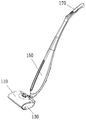
도 1은 본원 발명에 따른 바닥 청소기 일 실시예의 전체도이다.
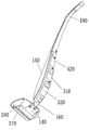
도 2는 도 1에 도시된 실시예의 다른 시각에 따른 전체도이다.
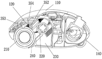
도 3은 도 1에 도시된 실시예의 분해 모식도이다.
도 4는 바닥 청소기의 베이스 부분의 단면 모식도이다.
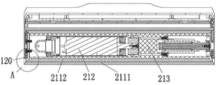
도 5는 바닥 청소기의 청소 롤러 어셈블리의 단면 모식도이다.
도 6은 도 5에서 A 부분의 확대도이다.
도 7은 바닥 청소기의 청소 롤러와 클리닝 기구의 협동 모식도이다.
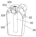
도 8은 바닥 청소기의 쓰레기 탱크의 모식도이다.
도 9는 바닥 청소기의 수조 구조(청소 롤러 어셈블리 포함)의 모식도이다.
도 10은 바닥 청소기의 수조 구조(청소 롤러 어셈블리 미포함)의 모식도이다.
도 11은 바닥 청소기의 급수 기구 모식도이다.
도 12는 바닥 청소기의 맑은 물 탱크 모식도이다.
도 13은 바닥 청소기의 오수 탱크 모식도이다.
도 14는 바닥 청소기의 워터 펌프 모식도이다.
도 15는 바닥 청소기의 공기 펌프 모식도이다.
도 16은 바닥 청소기의 오수 탱크의 입체 단면 모식도이다.
도 17은 바닥 청소기의 오수 탱크의 다른 단면 모식도이다.
도 18은 바닥 청소기의 스플래시 방지 부재의 단면 모식도이다.
도 19는 바닥 청소기의 스폰지 롤러의 입체 단면 모식도이다.
도 20은 바닥 청소기의 스폰지 롤러의 입체 단면 모식도이다.1 is an overall view of one embodiment of a floor cleaner according to the present invention.
2 is an overall view according to another aspect of the embodiment shown in Fig.
3 is a schematic exploded view of the embodiment shown in Fig.
4 is a schematic sectional view of the base portion of the floor cleaner.
5 is a schematic cross-sectional view of the cleaning roller assembly of the floor cleaner.
6 is an enlarged view of a portion A in Fig.
Fig. 7 is a schematic view showing the cooperation between the cleaning roller and the cleaning mechanism of the floor cleaner.
8 is a schematic view of a trash tank of a floor cleaner.
9 is a schematic view of a water tank structure (including a cleaning roller assembly) of a floor cleaner.
10 is a schematic view of a water tank structure (without the cleaning roller assembly) of the floor cleaner.
11 is a schematic diagram of a water supply mechanism of the floor cleaner.
12 is a schematic diagram of a clear water tank of the floor cleaner.
13 is a schematic diagram of a sewage tank of a floor cleaner.
14 is a schematic view of a water pump of a floor cleaner.
15 is a schematic view of an air pump of a floor cleaner.
16 is a three-dimensional sectional view schematically showing the sewage tank of the floor cleaner.
17 is another schematic cross-sectional view of the waste water tank of the floor cleaner.
18 is a sectional schematic view of the splash preventive member of the floor cleaner.
19 is a three-dimensional sectional view schematically showing the sponge roller of the floor cleaner.
20 is a three-dimensional sectional view schematically showing the sponge roller of the floor cleaner.
이하, 발명을 실시하기 위한 구체적인 내용과 도면을 결부시켜 본 발명을 보다 상세하게 설명한다. 본원 발명은 여러가지 다양한 형태로 구현될 수 있으며, 이하 발명을 실시하기 위한 구체적인 내용은 본원 발명에 공개된 내용을 보다 명확하고 완전히 이해하도록 제공되는 것일 뿐 본원 발명은 이에 한정되지 않는다. 여기서 상, 하, 좌, 우와 같이 방위를 나타내는 단어는 단지 대응되는 도면에서의 도시된 구조체 위치에 관한 것이다.Hereinafter, the present invention will be described in more detail by concretely describing the present invention with reference to the drawings. The present invention may be embodied in various other forms and specific embodiments for carrying out the invention are provided for clarity and thorough understanding of the present invention, but the present invention is not limited thereto. The terms bearing, such as up, down, left, and right, relate only to the depicted structure locations in the corresponding figures.
그러나 당업자는 이들 중 하나 또는 하나 이상에 대한 구체적인 설명을 생략할 수 있거나 다른 방법, 어셈블리 또는 재료를 적용할 수 있음을 이해할 수 있을 것이다. 부분적 예시에서 일부 실시형태는 설명되지 않았거나 자세히 설명되지 않을 수 있다.However, those skilled in the art will recognize that one of ordinary skill in the art may understand that one or more of these may not be specifically described or that other methods, assemblies, or materials may be applied. In the partial example, some embodiments are not described or may not be described in detail.
이 밖에, 본 명세서에 기재된 기술적 특징, 기술적 해결수단은 하나 또는 하나 이상의 실시예에서 임의의 적절한 방식으로 조합될 수 있다.In addition, the technical features and technical solutions described herein may be combined in any suitable manner in one or more embodiments.
실시예 1:Example 1:
본 실시예는 바닥 청소기를 제공한다.The present embodiment provides a floor cleaner.
상기 바닥 청소기는 케이스 어셈블리, 청소기구, 급수 기구, 제어 유닛 및 연결 기구를 포함한다.The floor cleaner includes a case assembly, a cleaning mechanism, a water supply mechanism, a control unit, and a connection mechanism.
상기 케이스 어셈블리는 바닥 청소기를 지지하기 위한 것으로, 베이스 및 핸들 두 부분으로 구분될 수 있다. 상기 베이스 및 핸들은 연결 기구를 통해 연결 가능하되, 사용자가 본 발명의 바닥 청소기를 보다 잘 제어하여 보다 많은 각도에서 청소를 수행할 수 있도록 가동적으로 연결될 수 있다.The case assembly is for supporting a floor cleaner and can be divided into two parts, a base and a handle. The base and the handle are connectable through a connection mechanism and can be operatively connected so that the user can better control the floor cleaner of the present invention and perform cleaning at more angles.
상기 청소기구는 바닥 청소를 수행하는 주요 부재로서, 통상적으로 베이스 상에 장착된다. 상기 급수 기구는 맑은 물 탱크와 오수 탱크를 제공 가능하되, 청소 수원이 저장된 상기 맑은 물 탱크는 청소기구와 연통되고, 청소기구가 세척을 수행하도록 동력부재를 통하여 청소기구에 맑은 물을 공급한다. 오수 탱크에는 그와 연통된 청소기구에서 기인된 오수가 저장된다. 청소기구 내의 오수는 다른 동력 부재의 작용하에 오수 탱크로 회수되어 오수가 바닥 청소기 외부로 유출되는 것을 방지한다.The cleaning mechanism is a main member for performing floor cleaning, and is usually mounted on a base. The water supply mechanism is capable of providing a clear water tank and a sewage tank. The clear water tank storing the cleaning water source communicates with the cleaning device, and supplies clean water to the cleaning device through the power member so that the cleaning device performs cleaning. In the sewage tank, the sewage caused by the cleaning device communicating with the sewage tank is stored. The wastewater in the cleaning device is returned to the wastewater tank under the action of the other power members to prevent the wastewater from flowing out of the floor cleaner.
제어 유닛은 주로 제어 회로 및 제어 회로가 로딩된 회로기판을 포함하고, 예를 들어 청소기구의 가동 및 정지, 급수 기구의 개방 및 정지, 인간-컴퓨터 상호 작용 구현 등 기타 부분을 제어하는 역할을 한다.The control unit mainly includes a circuit board on which the control circuit and the control circuit are loaded and serves to control other parts such as, for example, the operation and stoppage of the cleaning device, opening and stopping of the water supply mechanism, and implementation of human- .
이해의 편의를 위하여, 본 실시예에서는 베이스가 위치하는 측을 전방향, 핸들이 위치하는 측을 후방향으로 하여 후술한다.For convenience of understanding, in the present embodiment, the side on which the base is located is referred to as the front direction, and the side on which the handle is located is referred to as the rear direction.
구체적으로, 도 1 - 도 3을 참조하면, 상기 베이스는, 플립 케이스(110), 베이스 케이스(120), 사이드 커버 플레이트(130) 및 베이스 리어 케이스(140)를 포함하되, 상기 플립 케이스(110)는 베이스 케이스(120)의 상방에 장착되어 베이스 케이스(120)에 대해 뒤집어지며 열리고, 베이스 리어 케이스(140)는 베이스 케이스(120)의 뒤쪽 하방에 장착되며, 사이드 커버 플레이트(130)는 베이스 케이스(120)의 양측에 커버된다.1 to 3, the base includes a
계속하여 도 1 - 도 3을 참조하면, 핸들은 손잡이부 및 몸체부를 포함하되, 상기 손잡이부는, 손잡이 하이 하우징(170) 및 손잡이 리어 케이스(180)를 포함하고, 몸체부는, 몸체 하이 하우징(150) 및 몸체 리어 케이스(160)를 포함한다. 여기서, 손잡이부는 몸체부 상에 장착되고, 몸체부는 연결 기구(500)를 통해 베이스와 연결됨으로써 핸들과 베이스를 연결시킨다.1 to 3, the handle includes a handle portion and a body portion, the handle portion including a handle
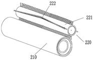
도 3 - 도 6을 참조하면, 상기 청소기구는, 청소 롤러 어셈블리(210); 청소 롤러의 쓰레기를 클리닝하기 위한 클리닝 기구(220); 및 청소 롤러 어셈블리의 쓰레기를 회수하기 위한 쓰레기 탱크(230)를 포함한다.3 to 6, the cleaning mechanism includes a cleaning
청소 롤러 어셈블리(210)는, 플렉시블 재료로 제조되고 바닥과 직접 접촉하여 바닥 쓰레기를 클리닝하는 청소 롤러를 포함한다. 본 실시예에서는 청소 롤러의 예시로서 스폰지 롤러(211)가 적용된다.The cleaning
청소 롤러 어셈블리(210)는, 스폰지 롤러(211)가 로딩되는 슬리브(213); 스폰지 롤러(211) 및 슬리브(213)를 회동 구동시키는 청소 동력 장치(212)를 더 포함한다.The cleaning
청소 동력 장치(212)는 베이스 케이스(120)에서 바닥과 수직되는 방향의 측벽 상에 장착되며 나사를 통해 체결될 수 있다. 스폰지 롤러(211)의 슬리브(213)는 청소 동력 장치(212)의 외면에 커버되며 탈착시켜 교체할 수 있다. 스폰지 롤러(211)는 슬리브(213)에 커버되고, 청소 동력 장치(212)는 슬리브(213) 내에 장착된다. 청소 동력 장치(212)는 모터일 수 있고, 제어 유닛으로 청소 동력 장치(212)의 온 오프 및 회동 방향 등을 제어한다.The
도 4를 참조하면, 상기 쓰레기 탱크(230)는 스폰지 롤러(211)의 뒤쪽 하방에 설치된다. 스폰지 롤러(211)의 회동에 영향을 미치지 않는 전제하에 가능한 한 스폰지 롤러(211)로부터 가깝게 위치하여 쓰레기가 스폰지 롤러(211)와 쓰레기 탱크(230) 사이의 틈새로부터 누출되는 것을 방지한다.Referring to FIG. 4, the
도 7을 참조하면, 상기 클리닝 기구(220)는 회동체(221) 및 회동체(221) 상에 설치된 복수의 클리닝 부재(222)를 포함한다. 상기 회동체(221)는 청소 동력 장치(청소 동력 장치는 모터일 수 있음. 도면에 미도시)에 의해 구동되어 회전하되, 스폰지 롤러(211)와 동일한 방향(시계 방향 또는 반시계 방향)으로 회전한다. 상기 클리닝 부재(222)는 브러쉬 또는 투스(tooth)와 같은 긴 스트립 형상을 가지며, 회동체(221)와 함께 회동한다. 회동과 동시에 스폰지 롤러(211)의 쓰레기가 클리닝되도록 클리닝 부재(222)와 스폰지 롤러(211) 사이에는 쓰레기 부피보다 더 작은 간극이 존재하거나 직접 접촉한다.Referring to FIG. 7, the
스폰지 롤러(211)에서 클리닝된 쓰레기가 쓰레기 탱크(230) 내에 유입되도록 클리닝 기구(220)는 스폰지 롤러(211)의 뒤쪽 상방, 즉 쓰레기 탱크(230)의 상방에 설치된다.The
도 7을 참조하면, 보다 효과적으로 스폰지 롤러(211)의 쓰레기를 클리닝하기 위하여 적어도 두개 그룹으로 클리닝 부재(222)를 설치할 수 있다. 각 그룹은 복수의 클리닝 부재(222)를 포함하고 회동체(221)를 따라 회전하여 중심선에 배열되되, 배열 길이는 회전 중심선 상의 스폰지 롤러(211) 길이보다 크거나 작거나 또는 같을 수 있다.Referring to FIG. 7, cleaning
계속하여 도 7을 참조하면, 각 그룹 클리닝 부재(222)의 배열은 직선에 따라 분포되거나 또는 각 그룹 클리닝 부재(222)를 웨이브 모양으로 배열시킬 수 있다. 이러한 배열 방식은 직선 배열 방식과 비교하여 스폰지 롤러(211)에서 발생되는 클리닝 부재(222)의 저항력 및 에너지 소모를 감소시킬 수 있다.7, the arrangement of each
나아가, 도 4 및 도 8을 참조하면, 바닥 청소기의 청소 효과를 상승시키기 위해 청소기구에서 스폰지 롤러(211)의 후방에 고무 등으로 제조되는 플렉시블 선단(241)을 구비하는 블레이드(240)가 설치된다. 상기 선단(241)은 바닥에 부착되어 쓰레기가 바닥 청소기로부터 하방으로 누락되는 것을 방지할 수 있다. 도 4및 도 10을 참조하면, 상기 블레이드(240)와 스폰지 롤러(211) 사이에는 간극이 형성되고, 블레이드(240)는 스폰지 롤러(211)의 외벽을 향하며 상기 간극이 쓰레기 유입을 인도하는 가이드 홈이 되도록 스폰지 롤러(211)와 대응되는 곡면으로 설계된다.4 and 8, in order to raise the cleaning effect of the floor cleaner, a
도 3, 도 4, 도 9 및 도 11을 참조하면, 상기 급수 기구는세척 챔버, 맑은 물 탱크(310), 맑은 물 공급 장치(본 실시예에서의 워터 펌프(330)), 오수 탱크(320) 및 오수 회수 장치(본 실시예에서의 공기 펌프(340))를 포함한다.3, 4, 9 and 11, the water supply mechanism includes a cleaning chamber, a
세척 챔버는 스폰지 롤러(211)의 회동 궤적 상에 설치되고, 스폰지 롤러(211)와 밀폐되게 매칭되며, 세척 챔버 내에는 수용액을 수용할 수 있으므로 스폰지 롤러(211)를 세척한다.The cleaning chamber is installed on the rotation locus of the
도 9 및 도 10을 참조하면, 본 실시예에서 제공되는 세척 챔버는 수조 구조이나 다른 실시예에서는 다른 형태의 챔버일 수도 있다. 상기 수조(351)는 베이스 케이스(120)(수조 케이스에 해당됨)의 일부분이 함몰되어 형성됨으로써 전체 바닥 청소기의 구조를 간소화시킬 수 있다. 그러나 다른 실시예에서, 상기 수조(351)는 별도의 수조 케이스로 형성될 수도 있다.Referring to Figures 9 and 10, the cleaning chamber provided in this embodiment may be a water tank structure or other types of chambers in other embodiments. The
상기 수조(351)는 스폰지 롤러(211)에 거꾸로 커버되고, 수조(351)와 스폰지 롤러(211)의 접촉 위치는 밀폐된 상태를 유지한다. 밀폐 구조를 구현하기 위하여, 본 실시예에서 수조(351)의 양측에는 나사를 통하여 각각 밀폐 부재(352) 및 링잉(wringing) 부재(353)가 체결된다. 여기서 밀폐 부재(352)는 링잉 부재(353)의 후방에 위치된다. 즉 스폰지 롤러(211)는 우선 밀폐 부재(352) 측으로 이동한 후, 다시 링잉 부재(353) 측으로 이동한다. 상기 링잉 부재(353) 및 밀폐 부재(352)는 각각 수조(351)와 스폰지 롤러(211)의 밀폐 구조인 동시에 링잉 부재(353)는 또한 스폰지 롤러(211) 내의 수분을 압출하는 역할을 수행한다. 스폰지 롤러(211)에서 압출된 오수는 직접 수조(351) 내로 유입되어 오수 탱크(320)에 의해 흡수된다.The
보다 우수한 링잉 효과를 위하여 링잉 부재(353)는 경질 재료를 적용하여 제조될 수 있다. 상기 링잉 부재(353)와 스폰지 롤러(211) 표면이 접촉되는 부분의 외벽은 아치형이되, 하드 플라스틱, 금속 등으로 제조되는 배턴(battens) 또는 축 형상 부재 등일 수 있고 밀폐 부재(352)는 밀폐 역할만 수행한다. 도 11을 참조하면, 밀폐 부재(352)와 스폰지 롤러(211)가 접촉되는 부분(3521)을 탄성 재료로 제조되는 볼록한 형상으로 설계할 수 있다. 상기 탄성은 스폰지 롤러(211)의 오수가 수조(351) 밖으로 압출되는 것을 방지할 수 있다.For a better ringing effect, the ringing
동시에, 스폰지 롤러(211)의 큰 고형 쓰레기가 급수 기구에 유입되어 수로가 차단되는 것을 방지하기 위하여 도 9 및 도 10을 참조하면, 수조(351) 내에는 링잉 부재(353) 및 밀폐 부재(352)에 의해 양단이 수조(351) 내에 눌리우는 여과망(354)을 더 설치할 수 있다. 9 and 10, in order to prevent the large solid waste of the
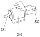
도 3, 도 11, 도 12 및 도 14를 참조하면, 맑은 물 탱크(310)의 맑은 물 출구(311), 수조(351)의 맑은 물 입구(도면에 미도시) 및 워터 펌프(330)는 서로 연통된다. 상기 워터 펌프(330)의 입수구(331)는 맑은 물 출구(311)와 연통되고, 출수구(332)는 맑은 물 입구와 연통되며, 워터 펌프(330)의 작용하에 맑은 물은 맑은 물 입구에 의해 수조(351)로 유입되어 스폰지 롤러(211)를 세척한 후 수조(351)의 오수 출구(1241)로 유출된다.3, 11, 12 and 14, the
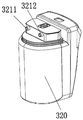
계속하여 도 3, 도 11, 도 13 및 도 15를 참조하면, 상기 오수 출구(1241), 오수 탱크(320)의 오수 입구(3211) 및 공기 펌프(340)는 서로 연통된다. 구체적으로, 상기 공기 펌프(340)는 오수 탱크(320)의 공기 추출구(3212)와 연통되고, 수조(351)의 오수 출구(1241)는 오수 탱크(320)의 오수 입구(3211)와 연통된다. 상기 공기 펌프(340)는 오수 탱크(320) 내에 부압이 발생하도록 오수 탱크(320)를 펌핑할 수 있다. 오수 탱크(320)는 상기 부압에 의해 수조(351) 내에서 오수를 흡입할 수 있다. 공기 펌프(340)를 이용해 오수를 흡입함으로써 오수 탱크(320)의 오수 흡입 기능을 쉽게 제어하고 실제 수요에 의해 원활히 조정할 수 있는 장점이 있다.3, 11, 13 and 15, the
물론, 다른 실시예에서 맑은 물 공급 장치는 워터 펌프(330)에 한정되지 않고 다른 구동 장치일 수도 있다. 예를 들어 공기 펌프로 상기 워터 펌프(330)를 대체할 수도 있다. 상기 공기 펌프는 수조(351)와 연통되어 공기를 펌핑시켜 수조(351) 내압을 감소시킴으로써 맑은 물 탱크(310) 내에서 맑은 물을 흡입하는데 이러한 원리는 상기 오수 탱크(320)의 오수 회수 원리와 유사하다.Of course, in other embodiments, the clear water supply device is not limited to the
마찬가지로, 오수 회수 장치는 공기 펌프(340)에 한정되지 않고 다른 구동 장치일 수도 있다. 예를 들어 워터 펌프로 공기 펌프(340)를 대체할 수 있는데 이러한 원리는 상기 맑은 물 탱크(310)의 맑은 물 공급 원리와 유사하다.Likewise, the waste water recovery device is not limited to the
나아가, 도 3, 도 11, 도 13, 도 15를 참조하면, 공기 펌프(340)의 공기 흡입구(341)와 오수 탱크(320)가 연통되어 있으므로 공기 펌프(340) 흡기 시 만약 오수 탱크(320)가 흔들린다면 비산되는 물거품이 쉽게 공기 펌프(340)에 의해 흡입될 수 있다.3, 11, 13, and 15, since the
본 실시예에서 구체적으로 하기와 같이 오수 탱크(320)를 개선시킨다. 오수 탱크(320)가 오수를 저장하는 수용 챔버와 적어도 하나의 스플래시 방지 부재를 구비하도록 설계하되, 상기 스플래시 방지 부재는 공기 추출구(3212)와 수용 챔버를 이격시키고, 스플래시 방지 부재에는 통기구가 개구되어 수용 챔버와 연통되며, 오수 탱크(320)의 공기 추출구(3212)와 스플래시 방지 부재의 통기구가 연통됨으로써 비산되는 물거품 대부분이 스플래시 방지 부재에 의해 차단되나 공기 펌프(340)의 펌핑에는 영향을 미치지 않는다. 여기서 스플래시 방지 부재의 수량이 많을수록 스플래시 방지 효과가 더 우수하다.In this embodiment, specifically, the
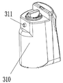
구체적으로, 도 16, 도 17 및 도 18을 참조하면, 오수 탱크(320)는, 오수 입구(3211) 및 공기 추출구(3212)가 설치된 챔버; 액체레벨 검출 장치(322); 및 스플래시 방지 부재(323);를 포함한다. 상기 액체레벨 검출 장치(322) 및 스플래시 방지 부재(323)는 모두 챔버 내에 장착되고, 액체레벨 검출 장치(322)는 오수 탱크(320) 내의 오수 액량을 검출하기 위한 것으로 이는 제어 유닛과 연결되어 오수가 최대치를 초과하기만 하면 스위치를 트리거시켜 제어 유닛으로 신호를 전송한다.16, 17, and 18, the
상기 스플래시 방지 부재(323)는, 상하로 설치된 제1 통기구(3231) 및 제2 통기구(3232)가 각각 개구된 제1 버퍼 챔버(3234)를 구비한다. 상기 제1 통기구(3231)와 제2 통기구(3232)는 상이한 방향에 설치되는데 제1 통기구(3231)는 수직 방향을 따라 설치될 수 있고 제2 통기구(3232)는 수용 챔버(3235)의 입구를 향하여 가로 방향으로 설치될 수 있다 이렇게 어긋나게 설치함으로써 제2 통기구(3232)로부터 유입된 수용액이 제1 통기구(3231)로 유입되는 것을 방지할 수 있다.The splash
스플래시 방지 부재(323)는 챔버 내에 장착 시 오수 탱크(320)의 챔버를 제2 버퍼 챔버(3233) 및 수용 챔버(3235)로 분할시키며, 수용 챔버(3235)와 제1 버퍼 챔버(3234)는 제2 통기구(3232)를 통해 연통되고, 제2 버퍼 챔버(3233)와 제1 버퍼 챔버(3234)는 제1 통기구(3231)를 통해 연통되며, 공기 추출구(3212)는 제2 버퍼 챔버(3233)와 연통된다. 공기 추출구(3212)는 가로 방향을 따라 설치될 수 있다. 따라서, 다단 스플래시를 통하여 물이 거의 공기 펌프(340) 내로 펌핑되지 않는다.
이 밖에, 오수 탱크(320)에서 비산되는 물거품이 공기 펌프(340)에 흡입되는 문제에 있어서 본 실시예는 다른 양상을 통하여 개선시킬 수도 있다. 즉 공기 펌프(340)의 배기구(342)를 스폰지 롤러(211) 또는 수조(351)와 연통시켜 공기 펌프(340)가 흡수한 수용액을 스폰지 롤러(211) 또는 수조(351)로 배출시킨다.In addition, the present embodiment can be improved through other aspects in the problem that the flocculant scattered in the
수조(351), 맑은 물 탱크(310), 워터 펌프(330), 오수 탱크(320) 및 공기 펌프(340) 사이의 수로는 모두 독립적인 덕트로 구현되거나 구조가 간소화되도록 다른 부재와 일체로 설계될 수 있다. 도 3 및 도 10을 참조하면, 베이스 케이스(120)의 양측에는 각각 맑은 물 홈, 오수 홈(124) 및 배수 홈(125)이 설치되되, 오수 홈(124)의 일단은 수조(351)의 오수 출구(1241)이고, 타단은 오수 탱크(320)와 연결되는 오수 연결구(1242)이며, 배수 홈(125)의 일단은 배수 입구(1251)이고, 타단은 수조(351) 또는 스폰지 롤러(211)와 연통되는 배수 출구(1252)이다. 맑은 물 홈은 케이스베이스(120)에서 오수 홈(124)과 대향하는 일측에 위치되어 워터 펌프(330)와 연통되는 연결구 및 수조(351)의 맑은 물 입구를 포함한다. 그 구조는 오수 홈(124)의 구조와 대체로 동일하므로 여기서 더 이상 자세히 설명하지 않는다. 베이스 케이스(120) 양측의 사이드 커버 플레이트(130)가 베이스 케이스(120) 상에 커버된 후, 상기 맑은 물 홈, 오수 홈(124) 및 배수 홈(125)은 모두 밀폐된 수로를 형성하여 수로를 연통시킨다.The water channel between the
나아가, 클리닝 효과를 향상시키기 위하여 스폰지 롤러(211)를 매우 두껍게 형성할 수 있으나 이로 인해 스폰지 세척 시 링잉 부재(353)가 스폰지 롤러(211)에 큰 힘을 가해야만 스폰지의 보다 깊은 부분의 물을 압출할 수 있게 된다. 그러나 링잉하는 힘이 너무 크면 스폰지 롤러(211)의 회전을 방해하게 되므로 스폰지 롤러(211)의 정상적인 회전을 유지하기 위해서는 에너지 인가를 증가시켜야 하므로 결국 에너지 과다 소모를 유발한다.Further, the
도 19 및 도 20을 참조하면, 본 실시예에서는 스폰지 롤러(211)를 적어도 두 층, 즉 외층에 위치한 흡수성 스폰지층(2111) 및 내층에 위치한 비 흡수성 스폰지층(2112)으로 설계한다. 상기 비 흡수성 스폰지층(2112)은 비 흡수성 스폰지 재료로 제조되므로 수분을 흡수할 수 없고, 흡수성 스폰지층(2111)은 흡수성 스폰지 재질로 제조되므로 수분은 주로 외층의 흡수성 스폰지층(2111)에 의해 흡수된다. 따라서 링잉 시, 외층의 흡수성 스폰지층(2111)의 수분만 압출하면 되는 것이다. 외층의 흡수성 스폰지층 두께가 기존의 전체 스폰지층보다 얇으므로 큰 링잉 파워가 필요없이 수분을 링잉할 수 있다. 따라서 스폰지 롤러(211)의 회동도 저애하지 않는다.Referring to Figs. 19 and 20, in this embodiment, the
나아가, 일반적으로 스폰지 롤러(211)는 베이스 케이스(120) 내에 장착된다. 종래의 원기둥형 스폰지 롤러의 양단은 바닥의 환형면에 수직되고 베이스 케이스(120)의 좌우 양측 벽은 일정한 두께를 가진다. 이러한 형상으로 인해 상기 스폰지 롤러(211)는 베이스 케이스(120) 및 스폰지 롤러(211)와 인접된 좌우 측벽의 하방으로 인입될 수 없으므로 베이스 케이스(120) 및 스폰지 롤러(211)와 인접된 좌우 측벽의 하방 영역은 클리닝 사각지대가 되는 것이다.Further, generally, the
본원 발명에서 제공되는 스폰지 롤러의 적어도 일단은 축방향을 따라 설치된 테이퍼면이다.At least one end of the sponge roller provided in the present invention is a tapered surface provided along the axial direction.
도 5, 도 6, 도 19 및 도 20을 참조하면, 본 실시예에서 제공되는 스폰지 롤러(211)의 양단은 테이퍼면(a, b)으로서, 상기 테이퍼면(a, b)은 장착된 후 베이스 케이스(120) 및 스폰지 롤러(211)와 인접된 좌우 측벽에서 바닥 측을 향하는 하방으로 인입될 수 있으므로 상기 클리닝 사각지대에 대해 클리닝을 수행한다.5, 6, 19 and 20, both ends of the
상기 제어 유닛은 제어 회로가 설치된 회로기판 및 인간 - 컴퓨터 교호 유닛 등을 포함한다. 제어 유닛이 본원 발명의 개선중점이 아니므로 단지 도 3에 인간 - 컴퓨터 교호 유닛 중 버튼만 도시될 뿐 여기서는 그 상세한 설명을 생략한다.The control unit includes a circuit board and a human-computer alternate unit in which a control circuit is installed. Since the control unit is not the focus of improvement of the present invention, only the buttons of the human-computer alternate unit are shown in Fig. 3, and a detailed description thereof will be omitted here.
이상 구체적인 예를 통해 본 발명을 설명하였으나 이는 단지 본 발명의 이해를 돕기 위한 것일 뿐 본 발명을 한정하는 것은 아니며 당업자는 본 발명의 사상에 따라 상기 발명의 실시를 위한 형태를 변경할 수 있다.While the present invention has been particularly shown and described with reference to exemplary embodiments thereof, it is to be understood that the invention is not limited to the disclosed embodiments, but, on the contrary, is intended to cover various modifications and equivalent arrangements included within the spirit and scope of the invention.
Claims (9)
상기 내부 스폰지층에 씌움 설치되고 흡수성 스폰지로 제조되는 외부 스폰지층;을 포함하는 것을 특징으로 하는 바닥 청소기의 스폰지 롤러.An inner sponge layer made of a non-absorbent sponge; And
And an outer sponge layer covering the inner sponge layer and made of an absorbent sponge.
상기 외부 스폰지층의 반경 방향 두께는 내부 스폰지층의 반경 방향 두께보다 얇은 것을 특징으로 하는 바닥 청소기의 스폰지 롤러.The method according to claim 1,
Wherein the radial thickness of the outer sponge layer is less than the radial thickness of the inner sponge layer.
상기 내부 스폰지층 및 외부 스폰지층 중 적어도 일단은 축 방향을 따라 설치된 테이퍼면을 구비하는 것을 특징으로 하는 바닥 청소기의 스폰지 롤러.The method according to claim 1,
Wherein at least one of the inner sponge layer and the outer sponge layer has a tapered surface provided along the axial direction.
상기 청소 동력 장치에 씌움 장착되는 슬리브(sleeve); 및
상기 슬리브에 씌움 장착되고 비 흡수성 스폰지로 제조되는 내부 스폰지층 및 상기 내부 스폰지층에 씌움 설치되고 흡수성 스폰지로 제조되는 외부 스폰지층을 포함하는 스폰지 롤러;를 포함하되,
상기 슬리브와 스폰지 롤러는 상기 청소 동력 장치의 구동에 의해 회전되어 바닥 내부 스폰지층 및 외부 스폰지층 청소를 수행하는 것을 특징으로 하는 바닥 청소기의 청소 롤러 어셈블리.Cleaning power unit;
A sleeve mounted on the cleaning power unit; And
A sponge roller comprising an inner sponge layer mounted on the sleeve and made of a nonabsorbable sponge, and an outer sponge layer mounted on the inner sponge layer and made of an absorbent sponge,
Wherein the sleeve and the sponge roller are rotated by driving the cleaning power unit to perform cleaning of the inner bottom sponge layer and the outer sponge layer.
상기 외부 스폰지층의 반경 방향 두께는 내부 스폰지층의 반경 방향 두께보다 얇은 것을 특징으로 하는 바닥 청소기의 청소 롤러 어셈블리.5. The method of claim 4,
Wherein the radial thickness of the outer sponge layer is less than the radial thickness of the inner sponge layer.
상기 내부 스폰지층 및 외부 스폰지층 중 적어도 일단은 축 방향을 따라 설치된 테이퍼면을 구비하는 것을 특징으로 하는 바닥 청소기의 청소 롤러 어셈블리.5. The method of claim 4,
Wherein at least one of the inner sponge layer and the outer sponge layer has a tapered surface provided along the axial direction.
바닥 청소를 위한 청소 롤러 어셈블리;를 포함하고,
상기 청소 롤러 어셈블리는,
청소 동력 장치;
상기 청소 동력 장치에 씌움 장착되는 슬리브; 및
상기 슬리브에 씌움 장착되고 비 흡수성 스폰지로 제조되는 내부 스폰지층과 상기 내부 스폰지층에 씌움 설치되고 흡수성 스폰지로 제조되어 상기 베이스 케이스에 장착되는 외부 스폰지층을 포함하는 스폰지 롤러를 포함하되,
상기 슬리브와 스폰지 롤러는 상기 청소 동력 장치의 구동에 의해 회전되어 바닥 청소를 수행하는 것을 특징으로 하는 바닥 청소기.A base case; And
A cleaning roller assembly for floor cleaning,
The cleaning roller assembly includes:
Cleaning power unit;
A sleeve mounted on the cleaning power unit; And
A sponge roller including an inner sponge layer mounted on the sleeve and made of a non-absorbent sponge, and an outer sponge layer covering the inner sponge layer and made of an absorbent sponge and mounted on the base case,
Wherein the sleeve and the sponge roller are rotated by driving the cleaning power device to perform floor cleaning.
상기 외부 스폰지층의 반경 방향 두께는 내부 스폰지층의 반경 방향 두께보다 얇은 것을 특징으로 하는 바닥 청소기.8. The method of claim 7,
Wherein the radial thickness of the outer sponge layer is less than the radial thickness of the inner sponge layer.
상기 내부 스폰지층 및 외부 스폰지층 중 적어도 일단은 축 방향을 따라 설치된 테이퍼면을 구비하되, 상기 테이퍼면의 최외곽은 상기 베이스 케이스로 삽입되어 바닥 측 하방을 향하는 것을 특징으로 하는 바닥 청소기.8. The method of claim 7,
Wherein at least one end of the inner sponge layer and the outer sponge layer has a tapered surface provided along the axial direction, and the outermost edge of the tapered surface is inserted into the base case and directed downward from the bottom side.
Applications Claiming Priority (1)
| Application Number | Priority Date | Filing Date | Title |
|---|---|---|---|
| PCT/CN2015/091683 WO2017059601A1 (en) | 2015-10-10 | 2015-10-10 | Floor cleaner, cleaning roller component, and sponge roller |
Publications (2)
| Publication Number | Publication Date |
|---|---|
| KR20180098228A true KR20180098228A (en) | 2018-09-03 |
| KR102093377B1 KR102093377B1 (en) | 2020-03-26 |
Family
ID=58487175
Family Applications (1)
| Application Number | Title | Priority Date | Filing Date |
|---|---|---|---|
| KR1020187013363A Active KR102093377B1 (en) | 2015-10-10 | 2015-10-10 | Floor cleaner, cleaning roller parts and sponge roller |
Country Status (10)
| Country | Link |
|---|---|
| US (2) | US10052007B2 (en) |
| EP (2) | EP3238596B1 (en) |
| JP (1) | JP2018506413A (en) |
| KR (1) | KR102093377B1 (en) |
| CN (1) | CN108135420B (en) |
| ES (1) | ES2746113T3 (en) |
| HU (1) | HUE045855T2 (en) |
| PL (1) | PL3238596T3 (en) |
| PT (1) | PT3238596T (en) |
| WO (1) | WO2017059601A1 (en) |
Cited By (2)
| Publication number | Priority date | Publication date | Assignee | Title |
|---|---|---|---|---|
| KR20200117361A (en) * | 2019-04-04 | 2020-10-14 | 삼성전자주식회사 | Cleaner and a method of manufacturing a brush drum of a cleaner |
| KR20210002902U (en) * | 2020-06-17 | 2021-12-24 | 선전 테크봇 인텔리전트 로봇 컴퍼니 리미티드 | Cleaning apparatus for cleaner robot |
Families Citing this family (27)
| Publication number | Priority date | Publication date | Assignee | Title |
|---|---|---|---|---|
| USD897059S1 (en) * | 2017-10-20 | 2020-09-22 | Shenzhen Hizero Technologies Co., Ltd. | Floor cleaner |
| CN110636790B (en) | 2018-02-13 | 2021-10-01 | 深圳市赫兹家电有限公司 | Sweeping robot and its cleaning device |
| IT201800010902A1 (en) * | 2018-12-07 | 2020-06-07 | Plastecs S R L | EQUIPMENT FOR TREATMENT OF WALKABLE SURFACES, SUCH AS FLOORS |
| EP3952712A1 (en) | 2019-04-12 | 2022-02-16 | Alfred Kärcher SE & Co. KG | Surface cleaning machine having a boost mode, and method for operating a surface cleaning machine |
| GB2584311B8 (en) * | 2019-05-30 | 2021-08-18 | Lupe Tech Limited | Rollers for vacuum cleaners |
| US11503976B2 (en) * | 2019-09-06 | 2022-11-22 | Brenda Stone | Cleaning apparatus |
| KR102209199B1 (en) | 2020-06-19 | 2021-01-29 | 홍연기 | Serration roller manufacturing and using method |
| CN113565054B (en) * | 2021-07-22 | 2023-10-31 | 安徽华信电动科技股份有限公司 | Small three-wheeled sanitation cleaning vehicle based on battery power |
| DE102021134552A1 (en) | 2021-12-23 | 2023-06-29 | Alfred Kärcher SE & Co. KG | Articulated floor cleaning machine and method of operating a floor cleaning machine |
| DE102021134577A1 (en) | 2021-12-23 | 2023-06-29 | Alfred Kärcher SE & Co. KG | Floor cleaning machine with kick tab and method for removing a dirt fluid tank assembly from a cleaning head |
| DE102021134612A1 (en) | 2021-12-23 | 2023-06-29 | Alfred Kärcher SE & Co. KG | Floor cleaning machine with at least one supporting element |
| DE102021134463A1 (en) | 2021-12-23 | 2023-07-13 | Alfred Kärcher SE & Co. KG | Surface cleaning machine with curved scraper element |
| DE102022102918A1 (en) | 2022-02-08 | 2023-08-10 | Alfred Kärcher SE & Co. KG | Floor cleaning device with cassette |
| DE102022102924A1 (en) | 2022-02-08 | 2023-08-10 | Alfred Kärcher SE & Co. KG | Floor cleaning device with movable scraper element |
| DE202022101312U1 (en) | 2022-02-08 | 2022-06-20 | Alfred Kärcher SE & Co. KG | Floor cleaning device with cassette |
| DE202022101313U1 (en) | 2022-02-08 | 2022-06-20 | Alfred Kärcher SE & Co. KG | Floor cleaning device with movable scraper element |
| EP4475732A1 (en) | 2022-02-08 | 2024-12-18 | Alfred Kärcher SE & Co. KG | Floor cleaning device with a pivot bearing unit with an abutment |
| WO2023151833A1 (en) | 2022-02-08 | 2023-08-17 | Alfred Kärcher SE & Co. KG | Floor cleaning device with a sweeping device and method for operating a floor cleaning device |
| DE102022133009A1 (en) | 2022-02-08 | 2023-08-10 | Alfred Kärcher SE & Co. KG | Floor cleaning device with pivot bearing device with counter bearing |
| DE102022102937A1 (en) | 2022-02-08 | 2023-08-10 | Alfred Kärcher SE & Co. KG | Floor cleaning device with dirt fluid tank |
| DE202022101314U1 (en) | 2022-02-08 | 2022-06-20 | Alfred Kärcher SE & Co. KG | Floor cleaning device with dirt fluid tank |
| GB2616903B (en) * | 2022-03-25 | 2024-06-26 | Dyson Technology Ltd | Hard floor cleaner |
| DE102022124120A1 (en) | 2022-09-20 | 2024-03-21 | Alfred Kärcher SE & Co. KG | Floor cleaning device with a basin and method for operating a floor cleaning device |
| DE102022133004A1 (en) | 2022-12-12 | 2024-06-13 | Alfred Kärcher SE & Co. KG | Floor cleaning device with floor head with wall |
| DE102022133006A1 (en) | 2022-12-12 | 2024-06-13 | Alfred Kärcher SE & Co. KG | Floor cleaning device with dirt fluid tank with two areas |
| CN120417818A (en) | 2023-02-16 | 2025-08-01 | 阿尔弗雷德·卡赫欧洲两合公司 | Floor cleaning machine with a base module and a cleaning module |
| DE102023104615A1 (en) | 2023-02-24 | 2024-08-29 | Alfred Kärcher SE & Co. KG | Surface cleaning machine with hot fluid generating device and method for operating a surface cleaning machine |
Citations (2)
| Publication number | Priority date | Publication date | Assignee | Title |
|---|---|---|---|---|
| US4959628A (en) * | 1988-07-22 | 1990-09-25 | Quad Research, Inc. | Rotating electric switch actuated by fixed magnetic means, usable for a surface cleaning device |
| US20090276975A1 (en) * | 2006-12-13 | 2009-11-12 | Electrolux Home Care Products, Inc. | Vacuum Cleaner Handle Lock |
Family Cites Families (25)
| Publication number | Priority date | Publication date | Assignee | Title |
|---|---|---|---|---|
| FR651101A (en) | 1927-03-29 | 1929-02-14 | Electrically operated scrubber | |
| US2881461A (en) * | 1956-10-29 | 1959-04-14 | Wynton E Parker | Paint roller for curved surfaces |
| US3172138A (en) * | 1963-09-16 | 1965-03-09 | William B Price | Surface treating apparatus |
| JPS5029975B2 (en) | 1972-04-24 | 1975-09-27 | ||
| CN2241510Y (en) | 1995-05-31 | 1996-12-04 | 谢嘉益 | A kind of swab |
| DE19805900C1 (en) * | 1998-02-13 | 1999-07-29 | Duepro Ag | Vacuum cleaner tool, esp. a floor suction nozzle, with pivotable brush roller |
| DE10001467B4 (en) * | 2000-01-15 | 2004-04-08 | Düpro AG | vacuum cleaning tool |
| US7279050B2 (en) | 2002-10-29 | 2007-10-09 | Xerox Corporation | One-piece bottom edge wipe sponge for cleaning a photoreceptor drum |
| US8079112B2 (en) | 2004-11-17 | 2011-12-20 | Butler Home Products, Llc | Disposable liquid absorbing cleaning pad for a hand held cleaning implement having an elongated handle |
| CN2794412Y (en) | 2005-04-09 | 2006-07-12 | 袁仁华 | Wet type drum vacuum cleaner |
| CN100581433C (en) * | 2007-03-29 | 2010-01-20 | 杜爵伟 | Floor cleaner in combination with floor wiping device with sweeping function |
| DE102007052982A1 (en) * | 2007-11-07 | 2009-05-14 | Vorwerk & Co. Interholding Gmbh | Cleaning device i.e. suction cleaning device, for use in handle-guided household-vacuum cleaner for floor cleaning i.e. wet floor cleaning, has cleaning cover fixedly attached to hollow body, and liquid barrier provided below cover |
| CN102087501A (en) * | 2009-12-02 | 2011-06-08 | 深圳市宝安区松岗富士(中国)制品厂 | Cleaning roller as well as manufacture method and manufacture die thereof |
| IT1402118B1 (en) * | 2010-09-15 | 2013-08-28 | Bettuzzi | DISHWASHER-SWEEPER MACHINE. |
| KR101573742B1 (en) | 2010-10-25 | 2015-12-07 | 삼성전자주식회사 | Autonomous cleaning device |
| JP5230775B2 (en) | 2011-06-09 | 2013-07-10 | 惠司 細川 | Condensation remover |
| KR101452617B1 (en) * | 2013-03-08 | 2014-10-22 | 박미경 | Vacuum cleaner with damp roller |
| US9682399B2 (en) * | 2013-03-15 | 2017-06-20 | Affordable Countertop Solutions, Inc. | Paint roller |
| TWM469037U (en) | 2013-05-07 | 2014-01-01 | qing-ji Lin | Electric sweep/wash device |
| CN203263303U (en) | 2013-05-23 | 2013-11-06 | 林清吉 | Electric sweeping and washing device |
| CN203506629U (en) | 2013-06-20 | 2014-04-02 | 苏州经贸职业技术学院 | Multifunctional cleaner |
| CN203458324U (en) | 2013-07-08 | 2014-03-05 | 范施嫡 | Glass wiper |
| US20150082579A1 (en) | 2013-09-26 | 2015-03-26 | Ching-Chi Lin | Electric sweeping washing device |
| CN204096530U (en) * | 2014-07-21 | 2015-01-14 | 安徽中瀚节能环保科技有限公司 | A kind of cavernous body cleans carrying roller |
| US9713411B2 (en) * | 2014-10-20 | 2017-07-25 | The Kirby Company / Scott Fetzer Company | Surface-treatment apparatus and head unit |
-
2015
- 2015-10-10 ES ES15905699T patent/ES2746113T3/en active Active
- 2015-10-10 EP EP15905699.3A patent/EP3238596B1/en active Active
- 2015-10-10 PL PL15905699T patent/PL3238596T3/en unknown
- 2015-10-10 PT PT15905699T patent/PT3238596T/en unknown
- 2015-10-10 HU HUE15905699A patent/HUE045855T2/en unknown
- 2015-10-10 US US15/122,437 patent/US10052007B2/en active Active
- 2015-10-10 WO PCT/CN2015/091683 patent/WO2017059601A1/en not_active Ceased
- 2015-10-10 JP JP2017563376A patent/JP2018506413A/en active Pending
- 2015-10-10 CN CN201580083997.4A patent/CN108135420B/en active Active
- 2015-10-10 EP EP19174624.7A patent/EP3556274A1/en not_active Withdrawn
- 2015-10-10 KR KR1020187013363A patent/KR102093377B1/en active Active
-
2018
- 2018-08-20 US US16/105,339 patent/US10898048B2/en active Active
Patent Citations (2)
| Publication number | Priority date | Publication date | Assignee | Title |
|---|---|---|---|---|
| US4959628A (en) * | 1988-07-22 | 1990-09-25 | Quad Research, Inc. | Rotating electric switch actuated by fixed magnetic means, usable for a surface cleaning device |
| US20090276975A1 (en) * | 2006-12-13 | 2009-11-12 | Electrolux Home Care Products, Inc. | Vacuum Cleaner Handle Lock |
Cited By (2)
| Publication number | Priority date | Publication date | Assignee | Title |
|---|---|---|---|---|
| KR20200117361A (en) * | 2019-04-04 | 2020-10-14 | 삼성전자주식회사 | Cleaner and a method of manufacturing a brush drum of a cleaner |
| KR20210002902U (en) * | 2020-06-17 | 2021-12-24 | 선전 테크봇 인텔리전트 로봇 컴퍼니 리미티드 | Cleaning apparatus for cleaner robot |
Also Published As
| Publication number | Publication date |
|---|---|
| US10052007B2 (en) | 2018-08-21 |
| KR102093377B1 (en) | 2020-03-26 |
| EP3238596A4 (en) | 2018-09-05 |
| HUE045855T2 (en) | 2020-01-28 |
| JP2018506413A (en) | 2018-03-08 |
| EP3238596B1 (en) | 2019-07-03 |
| PL3238596T3 (en) | 2020-02-28 |
| ES2746113T3 (en) | 2020-03-04 |
| CN108135420A (en) | 2018-06-08 |
| EP3556274A1 (en) | 2019-10-23 |
| US10898048B2 (en) | 2021-01-26 |
| EP3238596A1 (en) | 2017-11-01 |
| US20180199787A1 (en) | 2018-07-19 |
| WO2017059601A1 (en) | 2017-04-13 |
| CN108135420B (en) | 2021-04-09 |
| US20180353046A1 (en) | 2018-12-13 |
| PT3238596T (en) | 2019-08-06 |
Similar Documents
| Publication | Publication Date | Title |
|---|---|---|
| KR20180098228A (en) | Floor cleaner, cleaning roller parts and sponge roller | |
| KR102072512B1 (en) | Floor cleaner | |
| KR102072513B1 (en) | Floor cleaner and its water tank structure | |
| CN108348124B (en) | Floor cleaner and its cleaning cylinder cleaning structure | |
| JP2019115789A (en) | Floor cleaner | |
| JP2019107563A (en) | Floor cleaner and water tank structure thereof | |
| CN205181251U (en) | Floor cleaner , cleaning barrel subassembly and a sponge section of thick bamboo |
Legal Events
| Date | Code | Title | Description |
|---|---|---|---|
| PA0105 | International application |
St.27 status event code: A-0-1-A10-A15-nap-PA0105 |
|
| A201 | Request for examination | ||
| PA0201 | Request for examination |
St.27 status event code: A-1-2-D10-D11-exm-PA0201 |
|
| P11-X000 | Amendment of application requested |
St.27 status event code: A-2-2-P10-P11-nap-X000 |
|
| P13-X000 | Application amended |
St.27 status event code: A-2-2-P10-P13-nap-X000 |
|
| PG1501 | Laying open of application |
St.27 status event code: A-1-1-Q10-Q12-nap-PG1501 |
|
| E902 | Notification of reason for refusal | ||
| PE0902 | Notice of grounds for rejection |
St.27 status event code: A-1-2-D10-D21-exm-PE0902 |
|
| E13-X000 | Pre-grant limitation requested |
St.27 status event code: A-2-3-E10-E13-lim-X000 |
|
| P11-X000 | Amendment of application requested |
St.27 status event code: A-2-2-P10-P11-nap-X000 |
|
| P13-X000 | Application amended |
St.27 status event code: A-2-2-P10-P13-nap-X000 |
|
| T11-X000 | Administrative time limit extension requested |
St.27 status event code: U-3-3-T10-T11-oth-X000 |
|
| P11-X000 | Amendment of application requested |
St.27 status event code: A-2-2-P10-P11-nap-X000 |
|
| P13-X000 | Application amended |
St.27 status event code: A-2-2-P10-P13-nap-X000 |
|
| R17-X000 | Change to representative recorded |
St.27 status event code: A-3-3-R10-R17-oth-X000 |
|
| E701 | Decision to grant or registration of patent right | ||
| PE0701 | Decision of registration |
St.27 status event code: A-1-2-D10-D22-exm-PE0701 |
|
| GRNT | Written decision to grant | ||
| PR0701 | Registration of establishment |
St.27 status event code: A-2-4-F10-F11-exm-PR0701 |
|
| PR1002 | Payment of registration fee |
St.27 status event code: A-2-2-U10-U12-oth-PR1002 Fee payment year number: 1 |
|
| PG1601 | Publication of registration |
St.27 status event code: A-4-4-Q10-Q13-nap-PG1601 |
|
| R18-X000 | Changes to party contact information recorded |
St.27 status event code: A-5-5-R10-R18-oth-X000 |
|
| PN2301 | Change of applicant |
St.27 status event code: A-5-5-R10-R11-asn-PN2301 |
|
| PN2301 | Change of applicant |
St.27 status event code: A-5-5-R10-R14-asn-PN2301 |
|
| PR1001 | Payment of annual fee |
St.27 status event code: A-4-4-U10-U11-oth-PR1001 Fee payment year number: 4 |
|
| PR1001 | Payment of annual fee |
St.27 status event code: A-4-4-U10-U11-oth-PR1001 Fee payment year number: 5 |
|
| PR1001 | Payment of annual fee |
St.27 status event code: A-4-4-U10-U11-oth-PR1001 Fee payment year number: 6 |
|
| R18 | Changes to party contact information recorded |
Free format text: ST27 STATUS EVENT CODE: A-5-5-R10-R18-OTH-X000 (AS PROVIDED BY THE NATIONAL OFFICE) |
|
| R18-X000 | Changes to party contact information recorded |
St.27 status event code: A-5-5-R10-R18-oth-X000 |
|
| PR1001 | Payment of annual fee |
St.27 status event code: A-4-4-U10-U11-oth-PR1001 Fee payment year number: 7 |
|
| U11 | Full renewal or maintenance fee paid |
Free format text: ST27 STATUS EVENT CODE: A-4-4-U10-U11-OTH-PR1001 (AS PROVIDED BY THE NATIONAL OFFICE) Year of fee payment: 7 |