KR20180098157A - Box coating apparatus for vacuum coating of substrates, in particular spectacle lenses, and heating device for it - Google Patents
Box coating apparatus for vacuum coating of substrates, in particular spectacle lenses, and heating device for it Download PDFInfo
- Publication number
- KR20180098157A KR20180098157A KR1020180021294A KR20180021294A KR20180098157A KR 20180098157 A KR20180098157 A KR 20180098157A KR 1020180021294 A KR1020180021294 A KR 1020180021294A KR 20180021294 A KR20180021294 A KR 20180021294A KR 20180098157 A KR20180098157 A KR 20180098157A
- Authority
- KR
- South Korea
- Prior art keywords
- heating device
- vacuum chamber
- electrical
- stand
- hub portion
- Prior art date
- Legal status (The legal status is an assumption and is not a legal conclusion. Google has not performed a legal analysis and makes no representation as to the accuracy of the status listed.)
- Granted
Links
- 238000010438 heat treatment Methods 0.000 title claims abstract description 128
- 238000000576 coating method Methods 0.000 title claims abstract description 80
- 239000011248 coating agent Substances 0.000 title claims abstract description 69
- 239000000758 substrate Substances 0.000 title claims abstract description 43
- 238000001771 vacuum deposition Methods 0.000 title claims description 11
- 238000005485 electric heating Methods 0.000 claims abstract description 44
- 238000001704 evaporation Methods 0.000 claims abstract description 30
- 230000008020 evaporation Effects 0.000 claims abstract description 27
- 238000007689 inspection Methods 0.000 claims abstract description 11
- 239000000463 material Substances 0.000 claims abstract description 10
- 238000000746 purification Methods 0.000 claims abstract description 7
- 238000000034 method Methods 0.000 claims description 39
- 230000001681 protective effect Effects 0.000 claims description 16
- 230000005855 radiation Effects 0.000 claims description 12
- 238000009429 electrical wiring Methods 0.000 claims description 6
- 230000001154 acute effect Effects 0.000 claims description 5
- 239000010453 quartz Substances 0.000 claims description 5
- VYPSYNLAJGMNEJ-UHFFFAOYSA-N silicon dioxide Inorganic materials O=[Si]=O VYPSYNLAJGMNEJ-UHFFFAOYSA-N 0.000 claims description 5
- 230000008016 vaporization Effects 0.000 claims 1
- 238000005137 deposition process Methods 0.000 abstract description 4
- 239000007789 gas Substances 0.000 description 14
- 238000005086 pumping Methods 0.000 description 13
- 238000002955 isolation Methods 0.000 description 6
- 238000010998 test method Methods 0.000 description 6
- 238000013461 design Methods 0.000 description 5
- 238000009826 distribution Methods 0.000 description 5
- 230000000694 effects Effects 0.000 description 5
- 238000005240 physical vapour deposition Methods 0.000 description 5
- 239000002245 particle Substances 0.000 description 4
- 238000010926 purge Methods 0.000 description 4
- 238000012360 testing method Methods 0.000 description 4
- XLYOFNOQVPJJNP-UHFFFAOYSA-N water Substances O XLYOFNOQVPJJNP-UHFFFAOYSA-N 0.000 description 4
- 230000003667 anti-reflective effect Effects 0.000 description 3
- 239000013078 crystal Substances 0.000 description 3
- 238000012423 maintenance Methods 0.000 description 3
- 238000004519 manufacturing process Methods 0.000 description 3
- 238000002360 preparation method Methods 0.000 description 3
- 229910001220 stainless steel Inorganic materials 0.000 description 3
- 239000010935 stainless steel Substances 0.000 description 3
- IJGRMHOSHXDMSA-UHFFFAOYSA-N Atomic nitrogen Chemical compound N#N IJGRMHOSHXDMSA-UHFFFAOYSA-N 0.000 description 2
- QVGXLLKOCUKJST-UHFFFAOYSA-N atomic oxygen Chemical compound [O] QVGXLLKOCUKJST-UHFFFAOYSA-N 0.000 description 2
- 230000009286 beneficial effect Effects 0.000 description 2
- 238000011109 contamination Methods 0.000 description 2
- 230000006378 damage Effects 0.000 description 2
- 239000010408 film Substances 0.000 description 2
- 230000013011 mating Effects 0.000 description 2
- 238000005259 measurement Methods 0.000 description 2
- 239000001301 oxygen Substances 0.000 description 2
- 229910052760 oxygen Inorganic materials 0.000 description 2
- 238000003860 storage Methods 0.000 description 2
- 239000000126 substance Substances 0.000 description 2
- 238000002207 thermal evaporation Methods 0.000 description 2
- 239000010409 thin film Substances 0.000 description 2
- 238000000427 thin-film deposition Methods 0.000 description 2
- 239000011364 vaporized material Substances 0.000 description 2
- 230000002411 adverse Effects 0.000 description 1
- WYTGDNHDOZPMIW-RCBQFDQVSA-N alstonine Natural products C1=CC2=C3C=CC=CC3=NC2=C2N1C[C@H]1[C@H](C)OC=C(C(=O)OC)[C@H]1C2 WYTGDNHDOZPMIW-RCBQFDQVSA-N 0.000 description 1
- 238000013459 approach Methods 0.000 description 1
- 238000000429 assembly Methods 0.000 description 1
- 230000000712 assembly Effects 0.000 description 1
- 230000000903 blocking effect Effects 0.000 description 1
- 239000003795 chemical substances by application Substances 0.000 description 1
- 238000005253 cladding Methods 0.000 description 1
- 238000004140 cleaning Methods 0.000 description 1
- 239000000498 cooling water Substances 0.000 description 1
- 238000007872 degassing Methods 0.000 description 1
- 238000000151 deposition Methods 0.000 description 1
- 230000008021 deposition Effects 0.000 description 1
- 238000001514 detection method Methods 0.000 description 1
- 230000006866 deterioration Effects 0.000 description 1
- 230000009977 dual effect Effects 0.000 description 1
- 239000000428 dust Substances 0.000 description 1
- 230000004064 dysfunction Effects 0.000 description 1
- 230000005670 electromagnetic radiation Effects 0.000 description 1
- 239000011521 glass Substances 0.000 description 1
- 230000002209 hydrophobic effect Effects 0.000 description 1
- 229910010272 inorganic material Inorganic materials 0.000 description 1
- 239000011147 inorganic material Substances 0.000 description 1
- 230000003993 interaction Effects 0.000 description 1
- 239000000203 mixture Substances 0.000 description 1
- 229910052757 nitrogen Inorganic materials 0.000 description 1
- 230000003287 optical effect Effects 0.000 description 1
- 239000011368 organic material Substances 0.000 description 1
- 230000002093 peripheral effect Effects 0.000 description 1
- 230000001105 regulatory effect Effects 0.000 description 1
- 230000001846 repelling effect Effects 0.000 description 1
- 238000007789 sealing Methods 0.000 description 1
- 239000007787 solid Substances 0.000 description 1
- 230000003685 thermal hair damage Effects 0.000 description 1
- 238000013022 venting Methods 0.000 description 1
Images


Classifications
-
- C—CHEMISTRY; METALLURGY
- C23—COATING METALLIC MATERIAL; COATING MATERIAL WITH METALLIC MATERIAL; CHEMICAL SURFACE TREATMENT; DIFFUSION TREATMENT OF METALLIC MATERIAL; COATING BY VACUUM EVAPORATION, BY SPUTTERING, BY ION IMPLANTATION OR BY CHEMICAL VAPOUR DEPOSITION, IN GENERAL; INHIBITING CORROSION OF METALLIC MATERIAL OR INCRUSTATION IN GENERAL
- C23C—COATING METALLIC MATERIAL; COATING MATERIAL WITH METALLIC MATERIAL; SURFACE TREATMENT OF METALLIC MATERIAL BY DIFFUSION INTO THE SURFACE, BY CHEMICAL CONVERSION OR SUBSTITUTION; COATING BY VACUUM EVAPORATION, BY SPUTTERING, BY ION IMPLANTATION OR BY CHEMICAL VAPOUR DEPOSITION, IN GENERAL
- C23C14/00—Coating by vacuum evaporation, by sputtering or by ion implantation of the coating forming material
- C23C14/22—Coating by vacuum evaporation, by sputtering or by ion implantation of the coating forming material characterised by the process of coating
- C23C14/24—Vacuum evaporation
- C23C14/28—Vacuum evaporation by wave energy or particle radiation
- C23C14/30—Vacuum evaporation by wave energy or particle radiation by electron bombardment
-
- C—CHEMISTRY; METALLURGY
- C23—COATING METALLIC MATERIAL; COATING MATERIAL WITH METALLIC MATERIAL; CHEMICAL SURFACE TREATMENT; DIFFUSION TREATMENT OF METALLIC MATERIAL; COATING BY VACUUM EVAPORATION, BY SPUTTERING, BY ION IMPLANTATION OR BY CHEMICAL VAPOUR DEPOSITION, IN GENERAL; INHIBITING CORROSION OF METALLIC MATERIAL OR INCRUSTATION IN GENERAL
- C23C—COATING METALLIC MATERIAL; COATING MATERIAL WITH METALLIC MATERIAL; SURFACE TREATMENT OF METALLIC MATERIAL BY DIFFUSION INTO THE SURFACE, BY CHEMICAL CONVERSION OR SUBSTITUTION; COATING BY VACUUM EVAPORATION, BY SPUTTERING, BY ION IMPLANTATION OR BY CHEMICAL VAPOUR DEPOSITION, IN GENERAL
- C23C14/00—Coating by vacuum evaporation, by sputtering or by ion implantation of the coating forming material
- C23C14/22—Coating by vacuum evaporation, by sputtering or by ion implantation of the coating forming material characterised by the process of coating
- C23C14/24—Vacuum evaporation
- C23C14/28—Vacuum evaporation by wave energy or particle radiation
-
- C—CHEMISTRY; METALLURGY
- C23—COATING METALLIC MATERIAL; COATING MATERIAL WITH METALLIC MATERIAL; CHEMICAL SURFACE TREATMENT; DIFFUSION TREATMENT OF METALLIC MATERIAL; COATING BY VACUUM EVAPORATION, BY SPUTTERING, BY ION IMPLANTATION OR BY CHEMICAL VAPOUR DEPOSITION, IN GENERAL; INHIBITING CORROSION OF METALLIC MATERIAL OR INCRUSTATION IN GENERAL
- C23C—COATING METALLIC MATERIAL; COATING MATERIAL WITH METALLIC MATERIAL; SURFACE TREATMENT OF METALLIC MATERIAL BY DIFFUSION INTO THE SURFACE, BY CHEMICAL CONVERSION OR SUBSTITUTION; COATING BY VACUUM EVAPORATION, BY SPUTTERING, BY ION IMPLANTATION OR BY CHEMICAL VAPOUR DEPOSITION, IN GENERAL
- C23C14/00—Coating by vacuum evaporation, by sputtering or by ion implantation of the coating forming material
- C23C14/22—Coating by vacuum evaporation, by sputtering or by ion implantation of the coating forming material characterised by the process of coating
- C23C14/56—Apparatus specially adapted for continuous coating; Arrangements for maintaining the vacuum, e.g. vacuum locks
- C23C14/564—Means for minimising impurities in the coating chamber such as dust, moisture, residual gases
-
- C—CHEMISTRY; METALLURGY
- C23—COATING METALLIC MATERIAL; COATING MATERIAL WITH METALLIC MATERIAL; CHEMICAL SURFACE TREATMENT; DIFFUSION TREATMENT OF METALLIC MATERIAL; COATING BY VACUUM EVAPORATION, BY SPUTTERING, BY ION IMPLANTATION OR BY CHEMICAL VAPOUR DEPOSITION, IN GENERAL; INHIBITING CORROSION OF METALLIC MATERIAL OR INCRUSTATION IN GENERAL
- C23C—COATING METALLIC MATERIAL; COATING MATERIAL WITH METALLIC MATERIAL; SURFACE TREATMENT OF METALLIC MATERIAL BY DIFFUSION INTO THE SURFACE, BY CHEMICAL CONVERSION OR SUBSTITUTION; COATING BY VACUUM EVAPORATION, BY SPUTTERING, BY ION IMPLANTATION OR BY CHEMICAL VAPOUR DEPOSITION, IN GENERAL
- C23C14/00—Coating by vacuum evaporation, by sputtering or by ion implantation of the coating forming material
- C23C14/04—Coating on selected surface areas, e.g. using masks
-
- C—CHEMISTRY; METALLURGY
- C23—COATING METALLIC MATERIAL; COATING MATERIAL WITH METALLIC MATERIAL; CHEMICAL SURFACE TREATMENT; DIFFUSION TREATMENT OF METALLIC MATERIAL; COATING BY VACUUM EVAPORATION, BY SPUTTERING, BY ION IMPLANTATION OR BY CHEMICAL VAPOUR DEPOSITION, IN GENERAL; INHIBITING CORROSION OF METALLIC MATERIAL OR INCRUSTATION IN GENERAL
- C23C—COATING METALLIC MATERIAL; COATING MATERIAL WITH METALLIC MATERIAL; SURFACE TREATMENT OF METALLIC MATERIAL BY DIFFUSION INTO THE SURFACE, BY CHEMICAL CONVERSION OR SUBSTITUTION; COATING BY VACUUM EVAPORATION, BY SPUTTERING, BY ION IMPLANTATION OR BY CHEMICAL VAPOUR DEPOSITION, IN GENERAL
- C23C14/00—Coating by vacuum evaporation, by sputtering or by ion implantation of the coating forming material
- C23C14/22—Coating by vacuum evaporation, by sputtering or by ion implantation of the coating forming material characterised by the process of coating
- C23C14/24—Vacuum evaporation
-
- C—CHEMISTRY; METALLURGY
- C23—COATING METALLIC MATERIAL; COATING MATERIAL WITH METALLIC MATERIAL; CHEMICAL SURFACE TREATMENT; DIFFUSION TREATMENT OF METALLIC MATERIAL; COATING BY VACUUM EVAPORATION, BY SPUTTERING, BY ION IMPLANTATION OR BY CHEMICAL VAPOUR DEPOSITION, IN GENERAL; INHIBITING CORROSION OF METALLIC MATERIAL OR INCRUSTATION IN GENERAL
- C23C—COATING METALLIC MATERIAL; COATING MATERIAL WITH METALLIC MATERIAL; SURFACE TREATMENT OF METALLIC MATERIAL BY DIFFUSION INTO THE SURFACE, BY CHEMICAL CONVERSION OR SUBSTITUTION; COATING BY VACUUM EVAPORATION, BY SPUTTERING, BY ION IMPLANTATION OR BY CHEMICAL VAPOUR DEPOSITION, IN GENERAL
- C23C14/00—Coating by vacuum evaporation, by sputtering or by ion implantation of the coating forming material
- C23C14/22—Coating by vacuum evaporation, by sputtering or by ion implantation of the coating forming material characterised by the process of coating
- C23C14/50—Substrate holders
-
- G—PHYSICS
- G02—OPTICS
- G02B—OPTICAL ELEMENTS, SYSTEMS OR APPARATUS
- G02B1/00—Optical elements characterised by the material of which they are made; Optical coatings for optical elements
- G02B1/10—Optical coatings produced by application to, or surface treatment of, optical elements
- G02B1/11—Anti-reflection coatings
-
- G—PHYSICS
- G02—OPTICS
- G02C—SPECTACLES; SUNGLASSES OR GOGGLES INSOFAR AS THEY HAVE THE SAME FEATURES AS SPECTACLES; CONTACT LENSES
- G02C7/00—Optical parts
- G02C7/02—Lenses; Lens systems ; Methods of designing lenses
-
- H—ELECTRICITY
- H05—ELECTRIC TECHNIQUES NOT OTHERWISE PROVIDED FOR
- H05B—ELECTRIC HEATING; ELECTRIC LIGHT SOURCES NOT OTHERWISE PROVIDED FOR; CIRCUIT ARRANGEMENTS FOR ELECTRIC LIGHT SOURCES, IN GENERAL
- H05B3/00—Ohmic-resistance heating
- H05B3/0033—Heating devices using lamps
- H05B3/0038—Heating devices using lamps for industrial applications
Landscapes
- Chemical & Material Sciences (AREA)
- Organic Chemistry (AREA)
- Materials Engineering (AREA)
- Mechanical Engineering (AREA)
- Metallurgy (AREA)
- Chemical Kinetics & Catalysis (AREA)
- Engineering & Computer Science (AREA)
- Physics & Mathematics (AREA)
- Health & Medical Sciences (AREA)
- General Physics & Mathematics (AREA)
- Ophthalmology & Optometry (AREA)
- Optics & Photonics (AREA)
- Toxicology (AREA)
- General Health & Medical Sciences (AREA)
- Physical Vapour Deposition (AREA)
Abstract
기재를 코팅하기 위한 박스 코팅 장치(10)가 진공 챔버(12)를 포함하고, 이 진공 챔버는 코팅 재료를 증발시키기 위한 증발원(14) 및 기재 홀더(16)를 수용하고, 이 기재 홀더는 증발원과 마주하여 배치되어, 증발원에 의해 증발된 코팅 재료가 기재 홀더에 의해 유지되는 기재 상에 충돌할 수 있다. 전기 가열 장치(18)가 진공 챔버 안에 중심 배치되어 있고, 이 전기 가열 장치는 진공 검사 및 정화 과정의 경우에 진공 챔버를 가열하도록 되어 있다. 증착 공정 전에 진공 챔버로부터 제거될 수 있도록, 가열 장치에는, 베이스 판(36)에 장착되는 복수의 다리부(34)를 갖는 스탠드(20)가 제공되어 있고, 이 다리부는 가열 장치가 증발원의 위쪽에 걸쳐 배치될 수 있도록 크기 결정되어 있고 또한 베이스 판에 배치된다.A box coating apparatus (10) for coating a substrate comprises a vacuum chamber (12) which receives an evaporation source (14) and a substrate holder (16) for evaporating a coating material, So that the coating material vaporized by the evaporation source may impinge on the substrate held by the substrate holder. An electric heating device 18 is centered in the vacuum chamber, which is adapted to heat the vacuum chamber in the case of a vacuum inspection and purification process. The heating device is provided with a stand 20 having a plurality of legs 34 mounted on a base plate 36 so that the heating device can be removed from the vacuum chamber prior to the deposition process, And is also disposed on the base plate.
Description
본 발명은 일반적으로 청구항 1의 전제부에 따른, 기재의 진공 코팅을 위한 박스 코팅 장치에 관한 것이다. 일반적으로 이러한 장치는 통상적으로 광학 분야에 사용되는 다양한 유기 및 무기 재료의 기재 상에 다층 박막을 고진공으로 증착하기 위한 것이다. 특히, 본 발명은 안경 렌즈의 진공 코팅을 위한 박스 코팅 장치에 관한 것으로, 이 장치는 안경 렌즈의 대량 생산 구조 내에서 사용될 것이다. 이 경우, 전형적으로, 박스 코팅 장치는 안경 렌즈에 낮은 잔류 반사 및 원하는 색을 제공하기 위해 안경 렌즈 상에 다층 반사방지(AR) 코팅을 형성하기 위한 것이다. 그러나, 박스 코팅 장치는 다른 코팅 목적으로도 사용될 수 있는데, 예컨대, 소수성 코팅, 발유(oleophobic) 코팅 및 발진(dust repelling) 코팅을 포함하는 군에서 선택되는 탑 코팅(TC)을 그러한 AR 코팅 위에 형성하기 위해 사용될 수 있다. 본 발명은 또한 그러한 박스 코팅 장치를 위한 가열 장치에 관한 것으로, 이 가열 장치는 진공 검사 및 정화 과정의 경우에 주로 진공 챔버를 가열하는 역할을 한다.The present invention generally relates to a box coating apparatus for vacuum coating of a substrate, according to the preamble of claim 1. Generally, such devices are intended for high vacuum deposition of multilayer films on substrates of various organic and inorganic materials typically used in optical applications. In particular, the present invention relates to a box coating apparatus for vacuum coating of spectacle lenses, which apparatus will be used in a mass production structure of spectacle lenses. In this case, typically, the box coating apparatus is for forming a multilayer antireflective (AR) coating on the spectacle lens to provide low residual reflection and desired color to the spectacle lens. However, the box coating apparatus can also be used for other coating purposes, such as forming a top coating (TC) selected from the group including hydrophobic coatings, oleophobic coatings and dust repelling coatings on such AR coatings Lt; / RTI > The present invention also relates to a heating apparatus for such a box coating apparatus, wherein the heating apparatus mainly serves to heat the vacuum chamber in the case of a vacuum inspection and purification process.
관심 대상 코팅 기술(그 자체 알려져 있음)은 물리적 증기 증착(PVD) 공정인데, 더 정확하게 말하면, 열적 증발에 의한 코팅 공정이다. 열적 증발시, 증착 재료는 열적 가열 또는 전자 충돌에 의해 고체에서 증기 상태로 변하게 된다. 그런 다음, 증발된 재료는 박막의 성장이 일어나는 기재에 보내지게 된다. 이러한 코팅 기술의 중요한 파라미터는 주로 증발된 입자의 평균 속도 및 그 입자의 각 분포(angular distribution)이다. 공정이 일어나는 진공 챔버 안에서 증발 입자와 잔류 가스 사이의 충돌 횟수를 최소화하기 위해 기본 압력은 고진공 범위에서 유지되어야 한다. 고진공에 의해, 입자는 박막이 기재 레벨에서 성장하기에 충분한 "평균 자유 경로(mean free path)"를 가질 수 있다. 또한 고진공은, 증발된 재료가 증발기로부터 코팅 중인 표면에 전달될 때, 그 증발된 재료가 진공 챔버 내의 잔류 가스와 화학적으로 반응하지 않는 것을(또는 매우 제한된 정도로만 반응하도록) 보장해 준다. 이러한 이유로, 진공 챔버는 코팅이 시작되기 전에 예컨대 약 3 x 10⁻³ Pa 까지 펌핑 다운될 필요가 있다.The coating technique of interest (which is known per se) is a physical vapor deposition (PVD) process, or more precisely, a coating process by thermal evaporation. Upon thermal evaporation, the evaporation material changes from solid to vapor state by thermal heating or electron collision. The evaporated material is then sent to the substrate where the growth of the film takes place. Important parameters of this coating technique are mainly the average velocity of the evaporated particles and their angular distribution. The basic pressure should be maintained in the high vacuum range to minimize the number of collisions between the evaporated particles and the residual gas in the vacuum chamber in which the process takes place. By high vacuum, the particles can have a "mean free path" sufficient for the thin film to grow at the substrate level. The high vacuum also ensures that when the vaporized material is delivered from the evaporator to the surface being coated, the vaporized material will not chemically react (or only react to a very limited degree) with the residual gas in the vacuum chamber. For this reason, the vacuum chamber needs to be pumped down to, for example, about 3 x 10⁻³ Pa before the coating starts.
이를 위해, 알려져 있는 박스 코팅 장치, 예컨대, 스위스에 있는 본 출원인의 Satisloh AG에서 구입 가능한 박스 코팅 장치 "1200 DLX 박스 코팅기"는 특히 진공 챔버에 연결되어 있는 고진공 밸브 기구를 포함하는 펌핑 시스템을 가지며, 이의 기본 구조 및 기능은, 이때 명확히 참조할 본 출원인으로부터 구입 가능한 안내서인 "An Introduction To The Coating Of Ophthalmic Lenses"(2판, 2006)에 설명되어 있다.To this end, a known box coating apparatus, such as the box coating apparatus "1200 DLX box coater " available from Satisloh AG of the present Applicant in Switzerland, has a pumping system comprising a high vacuum valve mechanism, in particular connected to a vacuum chamber, Its basic structure and function is described in "An Introduction To The Coating Of Ophthalmic Lenses" (2nd edition, 2006), which is hereby incorporated by reference in its entirety.
이러한 고진공 시스템으로 작업하는 경우에는, 증착 공정 동안에 진공 레벨 및 성능에 영향을 줄 수 있는 진공 누설에 대해 진공 챔버를 지속적으로 검사해야 한다. 고진공 시스템에서 진공 누설이 생기면, 진공 챔버 내부의 최종 진공 값이 더 높게 되고 또한 잔류 가스의 질량 분포에 큰 영향을 줄 수 있는데, 진공 누설이 없는 고진공 시스템의 경우, 진공 챔버 내의 잔류 가스의 대부분은 일반적으로 물 분자로 나타나며, 반면 진공 누설의 경우에는, 잔류 가스는 물 외에도 질소 및 산소도 포함한다(표준 공기의 화학 조성에 따라). 그러므로 진공 누설은, 증발된 원자와 잔류 가스 사이의 기계적 산란 뿐만 아니라 진공 누설로 들어오는 산소와 증착된 층 사이의 화학적 상호 작용 때문에 PVD 공정 레벨에 큰 영향을 줄 수 있다.When working with such a high vacuum system, the vacuum chamber must be continuously inspected for vacuum leakage that can affect the vacuum level and performance during the deposition process. If a vacuum leak occurs in a high vacuum system, the final vacuum value inside the vacuum chamber becomes higher and can have a significant effect on the mass distribution of the residual gas. In a high vacuum system without vacuum leakage, most of the residual gas in the vacuum chamber In the case of vacuum leakage, the residual gas, in addition to water, also contains nitrogen and oxygen (depending on the chemical composition of the standard air). Vacuum leakage, therefore, can have a significant impact on the PVD process level due to mechanical scattering between the evaporated atoms and the residual gas, as well as chemical interactions between the oxygen entering the vacuum leak and the deposited layer.
진공 누설의 가능한 원인에 대해, 다른 진공 챔버 부품(스테인리스강 챔버 벽/용접부, 진공 챔버 내로의 기계적, 전기적 및 가스 피드 스루, 뷰포트, 가스켓 및 0-링과 같은 밀봉 수단 등)의 기계적 고장/악화 때문에, 또는 예컨대 O-링이 더러워지거나 손상되어 밀봉부를 따라 진공 누설을 야기하는 관련된 배기/개방 사이클을 갖는 진공 챔버의 펌핑 다운 동안에 박스 코팅 장치에서 진공 누설이 발생될 수 있다.Mechanical failure / deterioration of other vacuum chamber components (such as stainless steel chamber walls / welds, mechanical, electrical and gas feedthrough into vacuum chambers, sealing means such as viewports, gaskets and 0-rings, etc.) Vacuum leakage may occur in the box coating apparatus during pumping down of the vacuum chamber, for example, or with a related exhaust / open cycle, e.g., causing the O-ring to become dirty or damaged and causing vacuum leakage along the seal.
진공 누설의 존재를 검사하기 위해 다른 방법을 사용할 수 있다. 자주 사용되는 바람직한 일 누설 시험 방법은, 작업자가 필요 없고 박스 코팅 장치가 밤새 또는 주말 동안에 스스로 시험을 할 수 있도록 자동화될 수 있는 압력 상승 시험이다. 압력 상승 시험의 제 1 부분에서의 목표는, 박스 코팅 장치의 펌핑 시스템을 작동시키고 진공 챔버의 벽 및 진공 챔버 내의 다양한 기능 부품으로부터의 가스 제거율을 가능한 한 많이 줄여 진공 챔버 내에서 최선의 가능한 진공 레벨에 도달하는 것이다. 이전에, "베이크 아웃(bake out)" 공정을 통해 진공 챔버를 가능한 한 많이 정화시켜 가스 제거를 줄이기 위해 이 준비 단계 동안에 정상 가열 시스템이 사용된다.Other methods can be used to check for the presence of vacuum leakage. A preferred one-leak testing method that is often used is a pressure rise test that can be automated so that no operator is required and the box coating apparatus can be self-tested overnight or over the weekend. The goal in the first part of the pressure rise test is to operate the pumping system of the box coating apparatus and to reduce the gas removal rate from the various functional components in the walls of the vacuum chamber and the vacuum chamber as much as possible to achieve the best possible vacuum level Lt; / RTI > Previously, a normal heating system was used during this preparation phase to purify as much of the vacuum chamber as possible through a "bake out" process to reduce gas removal.
박스 코팅 장치 "1200 DLX 박스 코팅기"의 알려져 있는 정상 가열 시스템은 일반적으로 2개의 정상 가열기를 포함하는데, 이들 정상 가열기는 진공 챔버의 지붕 바로 아래에 있는 돔형 기재 홀더 위쪽에 고정적으로 설치되고 각기 전력을 공급 받는 구불구불한 줄(Joule) 효과 저항기를 가지고 있다. 정상 가열기는 코팅 공정 동안에 오염으로부터 보호되도록 적절한 고정식 차폐물 뒤에 숨어 있다.The known normal heating system of the box coating apparatus "1200 DLX box coater" generally comprises two normal heaters, which are fixedly mounted above the dome-shaped substrate holders directly below the roof of the vacuum chamber, It has a supplied joule effect resistor. The normal heater is hidden behind a suitable fixed shield to protect it from contamination during the coating process.
이 초기 베이크 아웃 공정 후에, 박스 코팅 장치는 누설률 측정 준비가 된다: 진공 챔버는 펌핑 시스템으로부터 절연되고(고진공 밸브가 차단됨) 또한 압력 상승율이 몇분 동안 모니터링된다. 누설률 값을 정의하기 위해 사용되는 식은 다음과 같다:After this initial bakeout process, the box coating apparatus is ready for leak rate measurement: the vacuum chamber is insulated from the pumping system (the high vacuum valve is shut off) and the rate of pressure rise is monitored for several minutes. The equation used to define the leak rate value is:
누설률 = (P1 - P0) x Vol / (T1 - T0)[Pa x 1/s]Leak rate = (P1 - P0) x Vol / (T1 - T0) [Pa x 1 / s]
여기서, T1 및 TO는 실험 시간 기간을 한정하고(예컨대, T1 - T0는 1800 초일 수 있음), P1 및 P0 는 진공 챔버에 설치되는 진공 게이지를 통해 T1 및 T0를 통해 얻어지는 압력 값이고, Vol은 진공 챔버의 부피이다. 박스 코팅 장치 "1200 DLX 박스 코팅기"의 경우 전형적인 양호한 누설률 값은 2.5 x 10-3 Pa x 1/s 미만일 수 있다. 누설률 값이 이 한계 아래인 경우, 진공 시스템은 진공의 관점에서 문제가 없으며, 박스 코팅 장치는 박막 PVD 공정을 위해 사용될 수 있다.Where T1 and T0 define the experimental time period (e.g., T1 - T0 may be 1800 seconds), P1 and P0 are pressure values obtained via T1 and T0 through a vacuum gauge installed in the vacuum chamber, It is the volume of the vacuum chamber. Typical good leak rate values for box coating equipment "1200 DLX box coater" may be less than 2.5 x 10-3 Pa x 1 / s. When the leak rate value is below this limit, the vacuum system is not problematic from the standpoint of vacuum, and the box coating apparatus can be used for the thin film PVD process.
이 문턱값 보다 높은 값은, PVD 공정의 질에 부정적으로 영향을 주기에 충분히 큰 누설이 존재하는 것을 암시한다. 불량한 누설률 값이 측정되면, 작업자는 소프트웨어로부터 경보 메시지를 받게 되고 누설을 수동으로 찾을 필요가 있다. 이 경우 작업자는 누설을 찾기 위해 일반적으로 누설 검출기를 사용할 것이다. 누설 검출 절차는 다소 시간 소비적이고 챔버 내 누설의 위치에 따라 복잡할 수 있다. 누설의 종류에 따라, 작은 부품 교체 또는 진공 챔버에 대한 훨씬 더 복잡하고 중요한 하드웨어/기계적 개입이 필요할 수 있다. 여하튼, 박스 코팅 장치는 누설을 찾아 제거한 후에만 다시 작동될 수 있다.Values higher than this threshold imply that there is a leakage large enough to adversely affect the quality of the PVD process. If a bad leak rate value is measured, the operator receives an alarm message from the software and needs to manually find the leak. In this case, the operator would normally use a leak detector to find the leak. The leakage detection procedure is somewhat time consuming and can be complicated by the location of the leakage in the chamber. Depending on the type of leakage, much more complex and critical hardware / mechanical interventions may be required for small parts replacement or vacuum chambers. Anyway, the box coating device can only be reactivated after finding and removing the leak.
박스 코팅 장치의 전술한 정상 가열 시스템은 유리 렌즈에 대한 일부 코팅 공정에 대해서는 극히 드문 경우에 사용될 수 있는데, 하지만 주로 1) 위에서 논의된 누설 시험 방법에 필요하거나(그 누설 시험 방법에서 정상 가열 시스템은 진공 챔버의 벽 및 그 안에 들어 있는 기능 부품을 가열하기 위해 열 방사선을 발생시켜 방출하는 역할을 함), 또는 2) 열로 가스 방출을 일으키는 동일한 효과를 사용하는 일부 정화 과정에 필요하다. 그럼에도 불구하고, 바람직하지 않은 오염 및 관련된 기능 장애에 대해 2개의 정상 가열기를 보호하는 고정식 차폐물을 갖는 알려진 정상 가열 시스템은, 항상 언더컷 영역 및 굴곡진 가스로 또는 증기로를 갖는 진공 챔버의 "거친(rugged)" 내면부를 형성하게 된다. 그러나 진공 챔버의 이 "거친" 내면부는 어떤 가스/증기 유동 저항을 수반하게 되며, 그래서, 진공 챔버를 위에서 언급한 공정 진공까지 펌핑 다운(pumping down)시키는 일은 상당히 시간 소비적일 수 있다. 물론, 안경 렌즈의 대량 생산에서는 그러한 비생산적인 하위 공정에 필요한 시간을 최소화하는 것이 바람직할 것이다.The above-mentioned normal heating system of the box coating apparatus can be used in extremely rare cases for some coating processes on glass lenses, but is largely required for 1) the leak test method discussed above (in the leak test method, Which serves to generate and emit heat radiation to heat the walls of the vacuum chamber and the functional components contained therein), or 2) some purification processes that use the same effect of causing gas emission to heat. Nonetheless, a known normal heating system with a fixed shield that protects the two normal heaters for undesirable contamination and related dysfunctions is always the undercut area and the "rough " rugged "inner surface. However, this " rough "inner surface of the vacuum chamber is subject to some gas / vapor flow resistance, and thus it can be quite time consuming to pumping down the vacuum chamber to the process vacuum mentioned above. Of course, in mass production of spectacle lenses it may be desirable to minimize the time required for such unproductive sub-processes.
따라서, 본 발명의 목적은, 위에서 개략적으로 설명한 종래 기술에서 출발하여, 단순화된 설계를 가지며 또한 증착 공정 전의 펌핑 다운 단계와 진공 검사 및 정화 과정의 준비시의 펌핑 다운 단계 동안에 향상된 펌핑 성능을 갖는, 기재, 특히 안경 렌즈의 진공 코팅을 위한 박스 코팅 장치를 제공하는 것이다. 상기 목적은 또한 진공 척 및 정화 과정의 경우에 진공 챔버를 가열하는 역할을 하는 관련된 가열 장치를 제공하는 것도 포함한다.It is therefore an object of the present invention to provide a process for the preparation of a vacuum pumping process which has a simplified design and which also has improved pumping performance during the pumping down step prior to the deposition process and during the preparation of the vacuum inspection and purging process, It is an object of the present invention to provide a box coating apparatus for vacuum coating a substrate, in particular, a spectacle lens. The object also includes providing a vacuum chuck and an associated heating device which serves to heat the vacuum chamber in the case of a purge process.
이 목적은 청구항 1에 나타나 있는 특징적 사항으로 달성된다. 본 발명의 유리한 또는 편리한 개량예는 청구항 2 내지 17에 나타나 있다.This object is achieved by the features set forth in claim 1. An advantageous or convenient improvement of the present invention is shown in
본 발명에 따르면(기재, 특히 안경 렌즈의 진공 코팅을 위한 박스 코팅 장치의 경우에, 진공 챔버를 포함하고, 상기 진공 챔버는 코팅 재료를 증발시키기 위한 증발원 및 복수의 기재를 유지하기 위한 기재 홀더를 수용하고, 상기 기재 홀더는 상기 증발원과 마주하여 배치되어 있어, 증발원에 의해 증발된 코팅 재료가 상기 기재 홀더에 의해 유지되는 기재 상에 충돌할 수 있고, 전기 가열 장치가 상기 진공 챔버 안에 배치되어 있고, 상기 전기 가열 장치는 진공 검사 및 정화 절차의 경우에 상기 진공 챔버를 가열하는 역할을 함), 상기 가열 장치에는, 상기 진공 챔버로부터 제거 가능하도록 되어 있는 스탠드가 제공되어 있고, 이 스탠드는 스탠드의 베이스 판에 장착되는 복수의 다리부를 가지며, 상기 다리부는 상기 가열 장치가 증발원의 위쪽에 걸쳐 배치될 수 있도록 크기 결정되어 있고 또한 상기 베이스 판에 배치된다.According to the invention (in the case of a box coating apparatus for the vacuum coating of a substrate, in particular a spectacle lens, it comprises a vacuum chamber, said vacuum chamber comprising an evaporation source for evaporating the coating material and a substrate holder for holding a plurality of substrates Wherein the substrate holder is disposed opposite the evaporation source so that the coating material evaporated by the evaporation source may impinge upon the substrate held by the substrate holder and an electric heating device is disposed in the vacuum chamber , The electric heating device serves to heat the vacuum chamber in the case of a vacuum inspection and purification procedure), the heating device is provided with a stand removable from the vacuum chamber, And a plurality of legs mounted on the base plate, wherein the legs are arranged so that the heating device The crystal size to chidoel and is also disposed on the base plate.
따라서, 가열 장치에 그 자체의 움직일 수 있는(제거 가능한) 스탠드를 제공함으로써, 종래 기술의 해결 방안으로서 사용되는 고정식 정상 가열기 시스템 대신에, 상기 가열 장치가, 검사 과정(누설률 시험 절차와 같은) 동안에 진공 챔버를 가열하거나 또는 표면 가스 제거(진공 챔버 및 그 안에 있는 기능 요소의 정화)를 일으키기 위해 사용될 수 있다. 그러나 실제 코팅 공정을 위해 가열 장치는 진공 챔버로부터 제거될 수 있다. 그러므로, 이러한 개념에 의해 박스 코팅 장치의 단순화된 설계가 가능하게 되는데, 가열 장치는 필요 없을 때는 제거될 수 있고 더욱이 일반적으로 안경 렌즈의 대량 생산의 경우에서처럼, 여러 개의 박스 코팅기가 제공되는 경우에는 하나 보다 많은 박스 코팅 장치를 위해 사용될 수 있다. 이렇게 박스 코팅 장치를 단순화시키면, 1) 코팅 공정 동안에 가열 장치 전체가 없을 수 있고 또한 진공 검사 및 정화 과정 동안에 가열 장치용 차폐물이 없을 수 있음으로 해서 가스 제거 표면이 작기 때문에 박스 코팅 장치의 펌핑 성능에 이득에 되고(진공 챔버를 펌핑 다운시키는 속도가 더 놓게 됨), 또한 2) 주기적으로 정화될 필요가 있는 피코팅 표면이 작기 때문에 박스 코팅 장치의 기계 유지 보수에도 이득이 된다. 많은 증착 사이클로 더러워지게 될(차폐되더라도) 알려져 있는 정상 가열 시스템과는 대조적으로, 제거 가능한 가열 장치는 박막 증착이 그 가열 장치에 도달하지 않을 것이기 때문에 더러워 지지 않을 것임을 주목해야 한다. 유리한 두 효과(펌핑 다운 시간의 감소 및 유지 보수 시간의 감소/듀티 사이클의 증가)로 인해, 결국 박스 코팅 장치의 생산성이 전체적으로 증가하게 된다.Thus, instead of a stationary normal heater system used as a solution to the prior art, by providing the heating device with its own movable (removable) stand, the heating device can be used as an inspection process (such as a leakage rate test procedure) Or to remove surface gases (purge of the vacuum chamber and the functional elements therein). However, the heating device can be removed from the vacuum chamber for the actual coating process. Therefore, this concept enables a simplified design of the box coating apparatus, which can be removed when not needed and, more generally, when several box coaters are provided, as in the case of mass production of spectacle lenses, It can be used for more box coating equipment. By simplifying the box coating apparatus in this way, it is possible to: 1) eliminate the entire heating apparatus during the coating process and, since there is no shield for the heating apparatus during the vacuum inspection and purge process, (The speed at which the vacuum chamber is pumped down further away), and 2) the mechanical maintenance of the box coating apparatus is beneficial because the surface to be coated, which needs to be periodically cleaned, is small. It should be noted that, in contrast to the normal heating system, which is known to be dirty with many deposition cycles (even if it is shielded), the removable heating device will not become dirty because thin film deposition will not reach the heating device. Two beneficial effects (reduced pumping down time and reduced maintenance time / increased duty cycle) result in an overall increase in the productivity of the box coating apparatus.
또한, 스탠드는 베이스 판에 장착되는 복수의 다리부를 가지며, 이 다리부는 가열 장치가 증발원의 위쪽에 걸쳐 배치될 수 있도록 크기 결정되어 있고 또한 베이스 판에 배치되므로, 가열 장치는 자유롭게 서 있는 방안이다. 예컨대 기재 홀더의 지지부에 "매달려 있는(hanging)" 배치와 비교하여, 자유롭게 서 있는 그러한 방안은 특히 작업자에게는 덜 성가신 것이다.Further, the stand has a plurality of legs mounted on the base plate, the legs being dimensioned so that the heating device can be placed over the evaporation source, and also placed on the base plate, so that the heating device is a free standing means. Such a stand-alone arrangement, for example, as compared to a "hanging" arrangement in the support of the substrate holder, is particularly less cumbersome for the operator.
바람직하게는, 가열 장치는 그의 스탠드와 함께 상기 증발원에 인접한 상기 진공 챔버의 중심 영역에 제거 가능하게 배치되도록 되어 있다. 이 결과, 가열 장치는 진공 챔버의 경계 벽 및 그 안에 들어 있는 기능 요소와 실질적으로 일정한 간격을 두고 있게 된다. 이러한 배치는, 특히 정상 가열 시스템에서의 이전에 알려져 있는 접근법과 비교하여, 훨씬 더 양호한 열 분포 및 그래서 또한 감소된 가스 제거 시간을 얻을 수 있게 해준다.Preferably, the heating device is arranged removably with a stand thereof in a central region of the vacuum chamber adjacent to the evaporation source. As a result, the heating device is spaced at a substantially constant distance from the boundary wall of the vacuum chamber and the functional elements contained therein. This arrangement makes it possible to obtain a much better heat distribution and thus also a reduced degassing time, in particular compared to previously known approaches in normal heating systems.
특히 셋업 시간을 짧게 하기 위해서는, 가열 장치는 이 가열 장치에 에너지를 공급하기 위한 전기 연결부를 포함하고 이 전기 연결부는 진공 챔버 내의 상대 전기 연결부에 연결되도록 되어 있는 것이 더 바람직하다. 예컨대, 가열 장치의 상기 전기 연결부는 신속 전기 플러그를 포함하고, 상기 진공 챔버 내의 상기 상대 전기 연결부는 공기-진공 전기 피드 스루(feed-through)를 통해 전기적으로 접촉되거나 또는 그 반대인 신속 전기 소켓을 가진다. 이리하여 또한, 상기 연결부는, 여러번 사용되는 나사 연결부 등과 비교하여, 실질적으로 마모되지 않는다는 이점이 얻어진다.In particular, in order to shorten the set-up time, it is more preferable that the heating device includes an electric connection part for supplying energy to the heating device, and the electric connection part is connected to the relative electric connection part in the vacuum chamber. For example, the electrical connection of the heating device may include a quick electrical plug, and the relative electrical connection in the vacuum chamber may include a quick electrical socket that is electrically contacted via air-vacuum electrical feed-through or vice versa I have. In this way, the connecting portion is advantageous in that it is not substantially worn as compared with a screw connection portion used many times.
바람직하게는, 박스 코팅 장치의 스탠드는 중심 축선을 가지며, 적어도 하나의 전기 가열 요소는 상기 중심 축선에 대해 본질적으로 반경 방향으로 열 방사선을 균일하게 방출하도록 상기 중심 축선 중심으로 배치된다. 마찬가지로, 이러한 설계는 모든 반경 방향으로 매우 양호한 열분포를 가능하게 하고 그래서 가스 제거 시간이 줄어 들게 된다. 다시 말해, 열 방사선을 단지 하나의 방향 또는 몇개의 방향으로만 보내는 반사기 등이 없다.Preferably, the stand of the box coating apparatus has a central axis, and at least one electric heating element is disposed about the center axis so as to uniformly emit thermal radiation in an essentially radial direction with respect to the central axis. Likewise, this design allows very good thermal distribution in all radial directions, thus reducing the degas time. In other words, there is no reflector or the like that sends thermal radiation in only one direction or in a few directions.
원리적으로, 가열 장치의 작동 상태에서 스탠드의 중심 축선이 실질적으로 수직 방향으로 연장되는 경우에는 단지 하나의 중심 전기 가열 요소가 있을 수 있지만, 가열 장치는 상기 스탠드의 원주에 걸쳐 스탠드의 중심 축선에 대해 균일하게 분포되어 있는 복수의 전기 가열 요소를 가지고 있는 것이 바람직하다. 이러면, 개별적인 전기 가열 요소가 진공 챔버 내의 인접 벽 또는 기능 요소에 더 가깝게 되어, 효율이 향상된다.In principle, there can be only one central electric heating element when the central axis of the stand extends in a substantially vertical direction in the operating state of the heating device, but the heating device is arranged on the center axis of the stand It is preferable to have a plurality of electric heating elements uniformly distributed with respect to each other. This allows the individual electric heating elements to be closer to the adjacent walls or functional elements in the vacuum chamber, thus improving efficiency.
본 발명의 개념을 계속하면, 전기 가열 요소의 구성은, 전기 가열 요소의 부품은 상기 중심 축선으로부터 멀어지게 위쪽으로 향하도록 상기 중심 축선에 대해 예각을 이루어 배치되고, 상기 전기 가열 요소의 다른 부품은 상기 중심 축선으로부터 멀어지게 아래쪽으로 향하도록 상기 중심 축선에 대해 예각을 이루어 배치되도록 될 수 있다. 이러한 배치에 의해서도 유리하게, 진공 챔버의 정상부 및 바닥부에서의 열 분포가 더 양호하게 된다.Continuing with the concept of the present invention, the configuration of the electric heating element is such that the parts of the electric heating element are disposed at an acute angle to the central axis so as to face upwardly away from the central axis, And may be arranged at an acute angle with respect to the central axis so as to face downward away from the central axis. This arrangement also advantageously results in better heat distribution at the top and bottom of the vacuum chamber.
기본적으로, "전구형(bulb-shaped)" 가열 램프가 가열 장치의 전기 가열 요소로서 사용될 수 있다. 그러나, 개별적인 전기 가열 요소의 방출 길이를 더 크게 하기 위해, 적어도 하나의 전기 가열 요소는 로드형인 것이 바람직하다.Basically, a "bulb-shaped" heating lamp can be used as the electric heating element of the heating device. However, in order to increase the emission length of the individual electric heating elements, it is preferred that at least one electric heating element is rod-shaped.
특히 가열 장치의 강성적이지만 경량인 설계를 위해서는, 스탠드는 적어도 하나의 프레임 바아에 의해 서로 단단히 연결되는 상측 허브 부분 및 하측 허브 부분을 가지며, 상기 적어도 하나의 전기 가열 요소는 상기 상측 허브 부분과 상기 하측 허브 부분 사이에 지지되는 것이 바람직하다. 이 경우, 전기 가열 요소는 직렬로 연결되는 전기 가열 요소의 쌍으로 배치되고, 전기 가열 요소의 상기 쌍은 상기 상측 허브 부분 및 하측 허브 부분의 각각의 공통 원주에서 상기 상측 허브 부분 및 하측 허브 부분에 부착되고, 중간 허브 부분이 제공되어 있고, 상기 중간 허브 부분은 상기 적어도 하나의 프레임 바아에 의해 상기 상측 허브 부분 및 하측 허브 부분에 단단히 연결되어 있고, 전기 가열 요소의 각 쌍의 전기 가열 요소를 이의 연결점에 인접해서 지지할 수 있다. 중간 허브 부분에 대한 직경을 상측 및 하측 허브 부분의 직경에 비해 크게 선택함으로써, 위에서 언급한 전기 가열 요소의 상향/하향 구성이 쉽게 얻어질 수 있다.Particularly for a rigid but lightweight design of the heating device, the stand has an upper hub portion and a lower hub portion which are tightly connected to each other by at least one frame bar, said at least one electric heating element comprising: And is preferably supported between the lower hub portions. In this case, the electric heating elements are arranged in pairs of serially connected electric heating elements, and the pair of electric heating elements are arranged in the common circumference of each of the upper hub part and the lower hub part to the upper hub part and the lower hub part Wherein the middle hub portion is rigidly connected to the upper hub portion and the lower hub portion by the at least one frame bar and the pair of electrical heating elements of the electrical heating element Adjacent to the connection point can be supported. By selecting the diameter of the middle hub portion to be larger than the diameter of the upper and lower hub portions, the upward / downward configuration of the above-mentioned electric heating element can be easily obtained.
마찬가지로, 경량의 설계를 이루고 또한 펌핑 시스템 쪽으로의 전도를 최대화하여 진공 챔버를 펌핑 다운시키기 위해 필요한 시간을 줄이기 위해, 허브 부분 및/또는 상기 베이스 판에는 통과 개구가 제공될 수 있다. 기본적으로 동일한 이유로, 허브 부분은, 내측 베이스부 및 이로부터 연장되어 있는 외측 아암부에 의해 평면도에서 볼 때 실질적으로 별 모양일 수 있고, 상기 전기 가열 요소는, 서로 인접하는 아암부 사이에서 각각의 허브 부분에 부착된다. 이 또한 전기 가열 요소 및 스탠드에 대한 그의 기계적 연결부를 손상으로부터 보호하는 데에 도움이 된다.Likewise, a through opening may be provided in the hub portion and / or the base plate to achieve a lightweight design and also to minimize the time required to pump down the vacuum chamber by maximizing conduction towards the pumping system. Basically for the same reason, the hub portion may be substantially star-shaped in plan view by the inner base portion and the outer arm portion extending therefrom, and the electric heating element may include a plurality of And is attached to the hub portion. This also helps to protect the electrical heating element and its mechanical connections to the stand from damage.
손상으로부터의 더욱더 큰 보호를 위해서는, 2개의 보호 바아가 각 전기 가열 요소에 할당되어 있고, 상기 보호 바아는, 본질적으로 상기 각각의 전기 가열 요소에서 반경 방향으로 방출되는 열 방사선을 차단함이 없이, 상기 보호 바아가 각각의 전기 가열 요소를 기계적 충격으로부터 보호하는 위치에 배치되어 있는 것이 더 바람직하다. 이 경우, 보호 바아는 바람직하게 상기 허브 부분의 상기 외측 아암부의 자유 단부에 부착되어, 전기 가열 요소를 위한 일종의 케이지를 형성한다.For even greater protection from damage, two protective bars are assigned to each electric heating element, and the protective bar is arranged in such a way that, without essentially shielding the heat radiation radially radiated from the respective electric heating element, It is further preferred that the protective bar is disposed at a position that protects each of the electric heating elements from mechanical impact. In this case, the protective bar is preferably attached to the free end of the outer arm portion of the hub portion to form a sort of cage for the electric heating element.
일 바람직한 실시 형태에서, 가열 장치는, 허브 부분을 통과해서 연장되어 배치되는 중심 포스트를 더 가지며, 이 중심 포스트는, 상기 전기 가열 요소를 위한 전기 배선을 수용하기 위해 관형으로 되어 있다. 따라서, 하나의 동일한 부품, 즉 중심 포트가 스탠드를 강성화시키고 동시에 기계적 및 열 손상으로부터 전기 배선을 보호해준다.In a preferred embodiment, the heating device further comprises a central post extending through the hub portion, the central post being tubular to receive electrical wiring for the electrical heating element. Thus, one identical part, the center port, stiffens the stand and simultaneously protects electrical wiring from mechanical and thermal damage.
또한, 가열 장치의 스탠드에는 상기 가열 장치를 이동시키고 위치시킬 수 있게 해주는 적어도 하나의 핸들이 유리하게 제공될 수 있어, 작업자에 의한 가열 장치의 취급을 개선시키고 용이하게 해준다.In addition, the stand of the heating device can advantageously be provided with at least one handle that allows the heating device to be moved and positioned, thereby improving and facilitating the handling of the heating device by the operator.
마지막으로, 적어도 하나의 가열 요소는 전기 적외선 석영 램프이다. 이러한 램프는 진공 하에서 사용되기에 특히 적합하고, 시중에서 쉽게 또한 비용 효과적으로 구입 가능한데, 예컨대, 2.000 W의 램프 와트수(wattage) 및 235 V의 작동 전압을 갖는 네덜란드 Philips Lighting의 공업용 램프형 13168X일 수 있다. 이들 램프는 전류 유도 줄 효과로 신속하게 가열하고 가열 후에 IR(적외선) 범위의 전자기 방사선을 방출하게 된다. IR 방사선은 열 에너지가 진공 챔버의 벽 및 진공 챔버 내의 다른 기능 요소에 전달되는 작동 원리이다. 그러나, 진공 챔버 안에서 제거 가능한 스탠드에 중심 배치되는 구불구불한 줄 효과 저항기형 가열기를 사용하는 것도 가능할 것이다.Finally, the at least one heating element is an electric infrared quartz lamp. Such lamps are particularly suitable for use under vacuum and are readily and cost effectively available on the market, for example the industrial lamp type 13168X of the Philips Lighting of the Netherlands with a lamp wattage of 2.000 W and an operating voltage of 235 V have. These lamps quickly heat up with a current-guiding effect and emit electromagnetic radiation in the IR (infrared) range after heating. The IR radiation is an operating principle in which heat energy is transferred to the walls of the vacuum chamber and to other functional elements within the vacuum chamber. However, it would also be possible to use a serpentine strip effect heater that is centered on a removable stand within the vacuum chamber.
이하, 부분적으로 단순화된 또는 개략적인 첨부 도면을 참조하여, 안경 렌즈와 같은 기재의 진공 코팅을 위한 박스 코팅 장치의 바람직한 실시 형태 및 이러한 박스 코팅 장치에 사용되도록 되어 있는 제거 가능한 가열 장치의 바람직한 실시 형태를 가지고 본 발명을 더 상세히 설명한다.A preferred embodiment of a box coating apparatus for vacuum coating of a substrate such as a spectacle lens and a preferred embodiment of a removable heating apparatus intended for use in such a box coating apparatus will now be described with reference to the partially simplified or schematic accompanying drawings The present invention will be described in more detail.
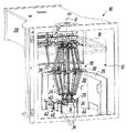
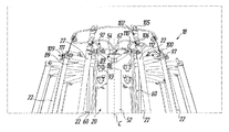
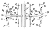
도 1은 진공 챔버 안에 있는 증발원과 마주하여 회전 중심 축선 중심으로 돔형 기재 홀더(파선으로 나타나 있음)에 의해 움직일 수 있게 유지될 수 있는 기재인 안경 렌즈의 특히 진공 코팅을 위한 본 발명에 따른 박스 코팅 장치를 위쪽 전방 좌측에서 비스듬히 본 사시도를 나타내며, 스탠드를 갖는 가열 장치가 증발원의 위쪽에서 진공 챔버의 중심 위치에 제거 가능하게 배치되어 있다.
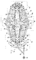
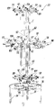
도 2는 도 1에 따른 박스 코팅 장치에서 제거된 상태에서 도 1에 따른 제거 가능한 가열 장치를 위쪽 전방에서 비스듬히 본 확대 사시도이다.
도 3은 도 2의 Ⅲ 부분에 대응하는 도 1에 따른 제거 가능한 가열 장치의 추가 확대 사시도를 나타낸다.
도 4는 도 2의 Ⅳ 부분에 대응하는 도 1에 따른 제거 가능한 가열 장치의 추가 확대 사시도를 나타낸다.
도 5는 도 2의 Ⅴ 부분에 대응하는 도 1에 따른 제거 가능한 가열 장치의 추가 확대 사시도를 나타낸다.
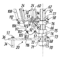
도 6은 도 1에 따른 박스 코팅 장치에서 제거된 상태에서 도 1에 따른 제거 가능한 가열 장치를 아래쪽 전방에서 비스듬히 확대 사시도이다.
도 7은 도 6의 Ⅶ 부분에 대응하는 도 1에 따른 제거 가능한 가열 장치의 추가 확대 사시도를 나타낸다.
도 8은 도 6의 Ⅷ 부분에 대응하는 도 1에 따른 제거 가능한 가열 장치의 추가 확대 사시도를 나타낸다.
도 9는 도 6의 Ⅸ 부분에 대응하는 도 1에 따른 제거 가능한 가열 장치의 추가 확대 사시도를 나타낸다.
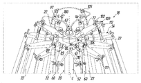
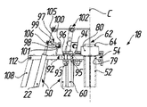
도 10은 도 1에 따른 박스 코팅 장치에서 제거된 상태에서 도 1에 따른 제거 가능한 가열 장치를 위쪽 전방 우측에서 비스듬히 본 확대 사시도를 나타내고, 가열 장치의 로드형 전기 적외선 석영 램프, 할당된 보호 바아, 그의 체결구, 및 석영 램프의 전기 연결부는 지지 구조를 더 잘 도시하기 위해 생략되었다.
도 11은 마찬가지로 지지 구조를 더 잘 도시하기 위해 도 10을 단순화시켜 도 1에 따른 박스 코팅 장치에서 제거된 상태에서 도 1에 따른 제거 가능한 가열 장치를 아래쪽 전방 우측에서 비스듬히 본 확대 사시도를 나타낸다.
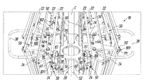
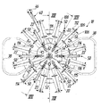
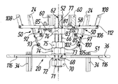
도 12는 도 1에 따른 박스 코팅 장치에서 제거된 상태에서 도 1에 따른 제거 가능한 가열 장치의 확대 상면도를 나타낸다.
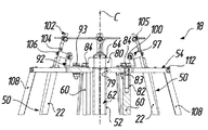
도 13a 내지 13c는 도 12의 ⅩⅢ - ⅩⅢ 단면선에 대응하는 도 1에 따른 제거 가능한 가열 장치의 추가 확대 절취 단면도를 나타낸다.
도 14a 내지 14c는 도 12의 ⅩⅣ - ⅩⅣ 단면선에 대응하는 도 1에 따른 제거 가능한 가열 장치의 추가 확대 절취 단면도를 나타낸다.Figure 1 shows a box coating according to the invention for a particularly vacuum coating of a spectacle lens which is a substrate which can be held movably by means of a dome shaped substrate holder (shown by the dashed line) about the center of rotation axis against the evaporation source in the vacuum chamber And a heating device having a stand is removably disposed at a central position of the vacuum chamber above the evaporation source.
FIG. 2 is an enlarged perspective view of a removable heating device according to FIG. 1 obliquely viewed from an upper front side in a state of being removed from the box coating apparatus according to FIG.
Fig. 3 shows a further enlarged perspective view of the removable heating device according to Fig. 1 corresponding to part III of Fig. 2;
Fig. 4 shows a further enlarged perspective view of the removable heating device according to Fig. 1 corresponding to part IV of Fig. 2;
Figure 5 shows a further enlarged perspective view of the removable heating device according to figure 1 corresponding to part V of figure 2;
FIG. 6 is an oblique perspective view of the removable heating device according to FIG. 1 in a state of being removed from the box coating apparatus according to FIG.
Fig. 7 shows a further enlarged perspective view of the removable heating device according to Fig. 1, corresponding to part VII of Fig. 6;
Fig. 8 shows a further enlarged perspective view of the removable heating device according to Fig. 1 corresponding to part VIII of Fig. 6;
Fig. 9 shows a further enlarged perspective view of the removable heating device according to Fig. 1 corresponding to part IX of Fig. 6;
FIG. 10 is an enlarged perspective view of a removable heating device according to FIG. 1 obliquely viewed from an upper front right side thereof in a state of being removed from the box coating apparatus according to FIG. 1, and shows a rod type electric infrared quartz lamp, Its fastener, and the electrical connections of the quartz lamp have been omitted in order to better illustrate the support structure.
Fig. 11 similarly shows an enlarged perspective view of the removable heating device according to Fig. 1 obliquely viewed from the lower front right side in a state in which the box coating apparatus according to Fig. 1 simplifies Fig. 10 in order to better show the supporting structure.
Fig. 12 shows an enlarged top view of the removable heating device according to Fig. 1 in a state removed from the box coating apparatus according to Fig.
13A to 13C show further enlarged cut-away cross-sectional views of the removable heating device according to Fig. 1 corresponding to the sectional lines XIII-XIII of Fig. 12;
Figs. 14A to 14C show additional enlarged cut-away cross-sectional views of the removable heating device according to Fig. 1 corresponding to the cross-sectional lines XIV to XIV in Fig.
이때 도 1과 관련하여, 도시의 단순화를 위해, 박스 코팅 장치의 클래딩(cladding), 벽 및 도어의 부품 외에, 특히, 셔터를 갖는 전자 비임 총, 작동 유닛과 제어 시스템(전기 캐비넷), 스크린, 기재와 소모품을 위한 취급 장치와 배치 요소, 전류(변압기), 압축 공기, 진공(고진공 펌프 세트) 및 냉각수(물 열 조절기, 캐스케이드 냉각기, 물 냉각기)를 위한 공급 및 조절 장치(라인, 호스 및 관을 포함하여), 또한 측정 장치, 유지 보수 장치 및 안전 장치는, 모든 경우에 본 발명의 이해에 필요 없다는 점에서 도 1에서 대부분 생략되었음을 유의해야 한다. 적어도 이들 생략된 부품, 어셈블리 및 장치의 구조 및 기능은 통상의 기술자에게 알려져 있다.1, in addition to the cladding of the box coating apparatus, the parts of the wall and the door, in particular for the simplification of the figure, an electronic beam gun with a shutter, an operating unit and a control system (electric cabinet) Supply and regulating devices (lines, hoses and pipes) for handling and positioning elements, current (transformer), compressed air, vacuum (high vacuum pump set) and cooling water (water heat regulator, cascade cooler, water cooler) ), And measurement devices, maintenance devices, and safety devices are largely omitted in FIG. 1 in that they are not necessary for understanding the invention in all cases. The structure and function of at least these omitted parts, assemblies, and devices are known to those of ordinary skill in the art.
기재(도면에는 나타나 있지 않음), 특히 안경 렌즈의 진공 코팅을 위한 박스 코팅 장치가 도 1에 참조 번호 "10"으로 나타나 있다. 이 박스 코팅 장치(10)는 진공 챔버(12)를 가지며, 이 진공 챔버는 증발원(14) 및 복수의 기재를 유지하기 위한 기재 홀더(16)를 수용한다(일단 누설율 시험 절차가 수행되고 있으면 일반적으로 기재 홀더 및 그의 부품은 진공 챔버(12)로부터 제거되므로 기재 홀더는 도 1에서 파선으로만 나타나 있음). 기재 홀더(16)는, 예컨대 위에서 언급한 박스 코팅 장치 "1200-DLX 박스 코팅기"에서 알려져 있는 바와 같은 방식으로, 증발원(14)과 마주하여 배치되고 증발원(14)을 통과하는 회전 축선(R) 주위로 돔 회전 구동기(나타나 있지 않음)에 의해 회전될 수 있는 돔(dome)으로 형성되어 있다. 따라서, 알려져 있는 방식으로 기재 홀더(16)에 의해 복수의 원 상에 유지되는 기재는 증발원(14)에 대해 각각의 일정한 간격을 두고 회전 축선(R) 주위의 원형 경로 상에서 움직일 수 있고, 증발원(14)에 의해 증발된 코팅 재료가 기재 홀더(16)에 의해 유지되는 기재 상에 충돌할 수 있다.A substrate (not shown), particularly a box coating apparatus for vacuum coating of spectacle lenses, is shown in FIG. 1 as "10 ". The
본질적인 특징에 따르면, 전기 가열 장치(18)가 진공 챔버(12)에 배치되어 있는데, 본 설명의 서두 부분에서 이미 논의한 바와 같이, 이 전기 가열 장치는 진공 검사 및 정화 과정의 경우에 진공 챔버(12)를 가열하는 역할을 한다. 아래에서 더 상세히 설명하는 바와 같이, 가열 장치(18)에는 스탠드(20)가 제공되어 있는데, 이 스탠드는 필요 없을 때, 즉 특히 실제 코팅 공정 동안에는 진공 챔버(12)로부터 제거될 수 있다.According to an essential feature, an
또한, 가열 장치(18) 자체는, 역시 아래에서 논의하는 바와 같이, 전기 가열 요소(22, 24)가 스탠드(20)의 중심 축선(C)에 대해 본질적으로 반경 방향으로 열 방사선을 균일하게 방출하도록 스탠드(20)의 중심 축선(C) 중심으로 배치되도록 설계되어 있다.The
박스 코팅 장치(10)의 추가 구조와 관련하여, 도 1은 진공 챔버(12) 안에 위치되는 마이스너(Meissner trap)(26)를 나타내는데, 이 마이스너 트랩은, 그 자체 알려져 있는 방식으로, 물 분자가 트랩 표면에 얼게 하여 자유로운 수증기를 진공 챔버(12) 안에 잡아 놓는 역할을 하고, 그래서 진공 챔버(12)를 펌핑 다운시키기 위해 필요한 시간이 줄어들 수 있다. 또한, 박스 코팅 장치(10)는 진공 챔버(12)에 대한 챔버 부속물(28)(박스 코팅 장치(10)의 "고진공 밸브 영역(high vacuum valve region)"으로도 알려져 있음)을 가지며, 그 챔버 부속물에는 고진공 밸브 기구(나타나 있지 않음)가 장착된다. 마이스너 트랩(26) 및 고진공 밸브 기구는 박막 증착에 민감하기 때문에, 완전 고정식 차폐물(30,32)이 코팅 공정 동안에 진공 챔버(12)를 통해 이동하는 증발 입자에 대해 각각의 장비를 보호하기 위해 증발원(14)과 대향하는 위치에서 진공 챔버(12) 안에 제공되어 있다. 차폐물(30)은 마이스너 트랩(26)의 앞에서 연속적인 벽을 형성하지만, 고진공 밸브 기구를 위한 차폐물(32)은 챔버 부속물(28)의 입구에 배치되고, 고정된 박판 각도를 갖는 박판 그리드 처럼 형성되어 있고, 그래서 각각의 박판 부분은 직접 증발원(14) 쪽을 향한다. 박스 코팅 장치의 민감한 요소를 보호하기 위한 완전한 고정식 차폐물 대신에, 본 출원인에 의해 2017년 2월 22일에 출원된 공동 계류 중인 유럽 특허 출원 17 000 280.2(이때 명백히 참조됨)에 개시되어 있는 바와 같이 각각의 공정 상태에 따라 선택적으로 개폐될 수 있는 차폐 장치(나타나 있지 않음)가 제공될 수 있다.1 shows a
중심 축선(C)이 실질적으로 수직 방향으로 연장되는 가열 장치(18)의 작동 상태를 도시하는 도 1과 관련하여 가열 장치(18)를 한번 더 보면, 도 1에 명확히 나타나 있는 바와 같이, 가열 장치(18)는 그의 스탠드(20)와 함께 증발원(14)에 인접한 진공 챔버(12)의 중심 영역에 제거 가능하게 배치되는 데에 적합한 형상 및 치수로 되어 있다. 이 위치에서 가열 장치(18)의 중심 축선(C)은 본질적으로 기재 홀더(16)의 회전 축선(R)과 정렬된다. 그러므로, 중심 축선(C)에 대해 반경 방향으로 볼 때, 가열 장치(18)는 진공 챔버(12)의 주변 벽으로부터 실질적으로 동일한 간격으로 떨어져 있다.1, which shows the operating state of the
도 1에서 더 알 수 있는 바와 같이, 스탠드(20)는 스탠드(20)의 베이스 판(36)에 장착되어 있는 복수의(나타나 있는 실시예에서 4개) 다리부(34)를 가지고 있고, 이들 다리부는 가열 장치(18)가 증발원(14)의 위쪽에 걸쳐 배치될 수 있도록 크기 결정되어 있고 또한 베이스 판(36)에 배치된다. 이를 위해, 나타나 있는 실시예의 스탠드(20)에는 스탠드(20)의 양 측에서 2개의 핸들(38)이 제공되어 있는데, 이 핸들은 진공 챔버(12) 안에서 가열 장치(18)를 자유롭게 이동시키고 위치시키거나 또는 진공 챔버(12)로부터 가열 장치(18)를 제거하여 경우에 따라 다른 박스 코팅 장치 또는 보관 공간에 전달할 수 있게 해준다.1, the
또한, 특히 도 1에 따르면, 가열 장치(18)는 가열 장치(18)에 에너지를 공급하기 위한 전기 연결부(40)를 포함하고, 이 전기 연결부는 상대 전기 연결부(42)에 연결되며, 상대 전기 연결부는 마이스너 트랩(26)을 위한 차폐물(30)의 앞에서 진공 챔버(12) 안에, 즉, 진공 증착의 바닥 영역(44)에 배치되어 있다. 더 정확하게 말하면, 가열 장치(18)의 전기 연결부(40)는 신속 전기 플러그(46)를 포함하고, 진공 챔버(12) 안에 있는 상대 전기 연결부(42)는 공기-진공 전기 피드 스루(나타나 있지 않음)를 통해 외부로부터 전기적으로 접촉되는 신속 전기 소켓(48)을 가지고 있으며, 이 소켓은 진공 챔버(12) 안에 가열 장치(18)의 "플러그 앤 런(plug and run)" 설치를 위한 신뢰적이고 내구적인 용이한 연결을 제공한다.1, the
이제 도 2 내지 14c를 참조하여 가열 장치(18)의 추가 상세를 설명할 것이다. 이때, 도면에 참조 번호가 과도하게 붙지 않도록 도면의 각각의 모든 곳에서 가열 장치(18)의 다양한 부분이 참조 번호로 나타나 있지는 않을 것이다. 그러나, 이와 관련하여, 가열 장치(18)는 스탠드(20)의 중심 축선(C) 중심으로 대칭적으로 배치되는 다수의 동일한 부품을 가지고 있음을 유의해야 하며, 따라서 통상의 기술자는, 참조 번호로 나타나 있지 않더라도, 특히 다양한 사시도에서 각각의 부품을 식별할 수 있을 것이다.Additional details of the
먼저, 도 2 및 6에서 가장 잘 알 수 있는 바와 같이, 가열 장치(18)는 스탠드(20)의 원주에 걸쳐 스탠드(20)의 중심 축선(C)에 대해 균일하게 분포되어 있는 복수의 전기 가열 요소(22, 24)를 가지고 있다. 더 정확하게 말하면, 본 실시 형태에서, 가열 장치(18)는 파워 및 형상(이 경우에는 로드형)에 있어 동일한 총 12개의 전기 가열 요소(22, 24), 즉 전기 적외선 석영 램프를 가지고 있다. 전기 가열 요소(22, 24)는 6개의 쌍(50)으로 배치되며, 각 쌍(50)의 전기 가열 요소(22, 24)는 연결점(49)에서 직렬로 연결되어 있다. 전기 가열 요소(22, 24)의 6개의 쌍(50)은 3-상(phase) 시스템(나타나 있지 않음)에서 서로 연결되어 있고 신속 전기 플러그(46)를 통해 전기적으로 연결될 수 있고, 3개의 상만 삼각형 구성으로 연결된다.First, as best seen in Figures 2 and 6, the
가열 장치(18)의 기계적 구조에 대해, 전기 가열 요소(22, 24)의 쌍(50)은, 위쪽에서 중심 축선(C) 주위의 원주 방향으로 볼 때(도 12 참조), 전기 가열 요소(22, 24)의 각 쌍(50)이 중심 축선(C) 중심으로 60°의 각도로 전기 가열 요소(22, 24)의 다음 쌍(50)으로부터 각도적으로 떨어져 있도록 스탠드(20)에 장착되어 있다. 또한, 높이 방향 및 중심 축선(C)에 대한 반경 방향으로 볼 때(도 2 및 6 참조), 각 쌍(50)의 전기 가열 요소(22, 24)는 둔각을 형성하도록 장착된다. 다시 말해, 쌍(50)의 전기 가열 요소(22, 24)는 이중 원추형의 표피를 함께 규정한다. 이 결과, 전기 가열 요소(22, 24)의 부품(즉, 6개의 상측 전기 가열 요소(22))은 중심 축선(C)에 대해 예각의 위쪽 방향으로 가열 장치(18)로부터 열 방사선을 더 큰 정도로 반경 방향으로 방출하도록 배치되어 있고, 반면, 전기 가열 요소(22, 24)의 다른 부품(즉, 6개의 하측 전기 가열 요소(24))은 중심 축선(C)에 대해 예각의 아래쪽 방향으로 가열 장치(18)로부터 열 방사선을 더 큰 정도로 반경 방향으로 방출하도록 배치되어 있다.With respect to the mechanical structure of the
특히 도 10 및 11에서 알 수 있는 바와 같이, 다리부(34) 및 베이스 판(36)(도 10에 있는 스크류 연결부(51)에 의해 서로에 부착되어 있음) 외에, 스탠드(20)의 주 요소(모두 스테인리스 강으로 만들어짐)는 중심 포스트(52), 상측 허브 부분(54), 중간 허브 부분(56), 하측 허브 부분(58) 및 6개의 프레임 바아(60)를 포함한다.10 and 11, in addition to the
도 13a 내지 14c에 따르면, 중심 포스트(52)는, 전기 가열 요소(22, 24)를 위한 전기 배선(62)을 수용하고 이 전기 배선을 위한 케이블 피드 스루로서 역할하기 위해 관형으로 있다. 중심 포스트는 허브 부분(54, 56, 58)을 통과해 배치된다. 더 정확하게 말하면, 중심 포스트(52)의 상측 및 하측 단부 각각에는 외부 나사산(64, 66)이 제공되어 있다. 중심 포스트(52)의 하측 단부는 베이스 판(36)에 있는 중심 장착 구멍(68)을 통과하여 연장되고, 아래쪽에서 외부 나사산(66) 상으로 나사 결합되는 너트(70), 유지 링(71) 및 와셔(72), 그리고 베이스 판(36) 위쪽에서 외부 나사산(66) 상으로 나사 결합되는 다른 와셔(73), 추가 너트(74) 및 상대 너트(75)를 통해 제자리에 고정된다. 상대 너트(75) 위쪽에서 다른 너트(76)는 하측 외부 나사산(66) 상으로 나사 결합되고, 이는 하측 허브 부분(58)을 중심 포스트(52)에 축방향으로 지지하는 역할을 한다. 그래서 중심 포스트(52)는, 다시 상측 허브 부분(54)에 있는 중심 위치 결정 구멍(79)(도 13a, 14a 참조)을 다시 타이트하게 통과할 때까지, 하측 허브 부분(58)에 있는 중심 위치 결정 구멍(77)(도 13c, 14c 참조)을 타이트하게 통과하여 연장되고 그리고 중간 허브 부분(56)에 있는 중심 통과 구멍(78)(도 13b, 14b 참조)을 반경 방향 유격을 가지고 통과하며, 상측 허브 부분(54)과 하측 하부 부분(58)을 함께 끌어 당기기 위해 추가 너트(80)가 중심 포스트(52)의 외부 나사산(64) 상으로 나사 결합된다.13A-14C, the center posts 52 are tubular to receive
동시에, 도 13a 내지 13c에 나타나 있는 바와 같이, 상측 허브 부분(54), 중간 허브 부분(56) 및 하측 허브 부분(58)은 6개의 프레임 바아(60)에 의해 서로 단단히 연결된다. 프레임 바아(60)(다리부(34) 처럼 단부 개방형 스패너 설치를 위한 키 결합 표면을 형성하기 위해 육각형 단면을 가지고 있음) 각각은 수 나사산 단부(81) 및 암 나사산 단부(82)를 포함한다. 또한, 각 허브 부분(54, 56, 58)은 동일한 직경에 있는 3개의 장착 구멍(83)을 가지며, 이들 장착 구멍은 중심 축선(C) 중심으로 120°각도로 서로 떨어져 있다. 도 13a에 따르면, 볼트(84)가 상측 허브 부분(54)의 장착 구멍(83)을 통과하여 상측 프레임 바아(60)의 암 나사산 단부(82) 안으로 나사 결합된다. 마찬가지로, 도 13b에 나타나 있는 바와 같이, 상측 프레임 바아(60)의 수 나사산 단부(81)는 중간 허브 부분(56)의 장착 구멍(83)을 통과하여 하측 프레임 바아(60)의 암 나사산 단부(82) 안으로 나사 결합된다. 마지막으로, 도 13c에 따르면, 하측 프레임 바아(60)의 수 나사산 단부(81)는 하측 허브 부분(58)에 있는 장착 구멍(83)을 통과하고, 너트(85)가 하측 프레임 바아(60)의 수 나사산 단부(81) 상에 나사 결합된다. 전술한 설명에서 명백한 바와 같이, 서로 평행하게 연장되어 있는 중심 포스트(52)와 프레임 바아(60)를 갖는 스탠드(20)의 지지 구조는 매우 강성적이고, 프레임 바아는 또한 허브 부분(54, 56, 58)이 중심 축선(C) 주위로 상대 회전하는 것을 방지한다.At the same time, the
도 10 및 11에서 더 알 수 있는 바와 같이, 허브 부분(54, 56, 58)은, 내측 베이스부(86, 87, 88) 및 이로부터 연장되어 있는 외측 아암부(89, 90, 91)(각 경우 12개)에 의해 평면도에서 볼 때 실질적으로 별 모양으로 되어 있다. 특히 도 3 내지 5 및 도 7 내지 9에 따르면, 전기 가열 요소(22, 24)는, 서로 인접하는 아암부(89, 90, 91) 사이에서 각각의 허브 부분(86, 87, 88)에 부착되어 있다. 이를 위해, 적절히 구부러진 장착 브라켓(92)이 나사 연결부(93)에 의해 허브 부분(54, 56, 58)의 각각의 내측 베이스부(86, 87, 88)에 부착되어 있다. 특히 도 14a 내지 14c에 따르면, 상측 허브 부분(54) 및 하측 허브 부분(58)에서 각 장착 브라켓(92)에 할당되어 있는, 또는 중간 허브 부분(56)의 경우에는 한쌍의 상호 반대편 장착 브라켓(92)에 할당되어 있는 핀(94)에 의해 장착 브라켓(92)은 각각의 나사 연결부(93) 주위로 회전하지 못한다. 각 핀(94)은 각각의 허브 부분(54, 56, 58)의 할당된 장착 구멍(95)(도 14a 내지 14 참조) 안에 압입 끼워 맞춤되고, 관련된 장착 브라켓(92)에 있는 할당된 기다란 위치결정 구멍(96)을 통과한다.As can be further seen in Figures 10 and 11, the
각 장착 브라켓(92)은 그의 각각의 자유 단부에서 격리 슬리브(97)를 가지고 있는데, 도 14a 내지 14c에서 알 수 있는 바와 같이, 이 격리 슬리브는 서로 반대편에 있는 암 나사산 단부(98, 99)를 가지고 있다. 각 장착 브라켓(92)의 자유 단부에 있는 장착 구멍(101)을 볼트(100)가 통과하여 관련된 격리 슬리브(97)의 암 나사산 단부(98) 안으로 나사 결합되어, 격리 슬리브를 각각의 장착 브라켓(92)에 안정적으로 고정시키게 된다(도 14a 참조). 또한, 각 전기 가열 요소(22, 24)는 양 단부에서 접촉 탭(tab)(102)을 가지고 있으며, 이 접촉 탭 각각에는 외측 접촉 구멍(103)(도 14c 참조) 및 기다란 내측 장착 구멍(104)(도 13a 참조)이 제공되어 있다. 접촉 구멍(103)은, 가열 장치(18)의 전기 배선(62)을 전기 가열 요소(22, 24)에 연결하고 또한 나사 연결부(105)의 도움으로 전기 가열 요소들을 연결점(49)에서 서로 연결하는 역할을 하고, 장착 구멍(104)은 전기 가열 요소(22, 24)를 스탠드(20)에 기계적으로 고정시키는 역할을 한다. 더 정확하게 말하면, 각각의 접촉 탭(102)을 관련된 격리 슬리브(97)에 체결하여 각각의 전기 가열 요소(22, 24)를 제자리에 단단히 유지시키기 위해 접촉 탭(102)의 장착 구멍(104)까지 연장되어 격리 슬리브(97)의 암 나사산 단부(99) 안으로 나사 결합되는 볼트(106)가 제공되어 있다.Each of the mounting
결과적으로, 특히 도 2 및 6에서 알 수 있는 바와 같이, 전기 가열 요소(22, 24)의 쌍(50)은 상측 허브 부분(54)과 하측 허브 부분(58)의 각각의 공통 원주에서 상측 허브 부분과 하측 허브 부분 사이에 지지되어 그에 부착되고, 중간 허브 부분(56)은 또한 중간 허브 부분(56)의 공통 원주에서 연결점(49)에 인접한 전기 가열 요소(22, 24)의 각 쌍(50)의 전기 가열 요소(22, 24)를 지지한다. 서로 다른 허브 부분(54, 56, 58)에서의 장착 직경이 다르기 때문에, 가열 장치(18)의 전체적인 모습은 이중 원추형이다.Consequently, as can be seen in particular in Figures 2 and 6, the
또한, 도 2 내지 9에 따르면, 각각의 전기 가열 요소(22, 24)에 2개의 보호 바아(108)가 할당되어 있는데(즉, 총 24개의 보호 바아(108)가 있음), 이들 보호 바아는, 본질적으로 각각의 전기 가열 요소(22, 24)에서 반경 방향으로 방출되는 열 방사선을 차단함이, 각각의 전기 가열 요소(22, 24)를 기계적 충격으로부터 보호하는 위치에 배치된다. 더 정확하게 말하면, 스테인리스 강의 평평한 스트립 재료로 만들어지는 보호 바아(108)는 허브 부분(54, 56, 58)의 외측 아암부(89, 90, 91)의 자유 단부에 부착된다. 이를 위해, 도 3 내지 5 및 도 7 내지 9에서 알 수 있는 바와 같이, 아암부(89, 90, 91)의 자유 단부에는, 보호 바아(108)의 단부를 수용하기 위한 슬릿(109)이 제공되어 있고, 보호 바아 각각에는 횡방향 장착 구멍(110)이 제공되어 있다. 마찬가지로, 아암부(89, 90, 91)의 자유 단부 각각에는 각각의 슬릿(109)의 영역에서 횡방향 구멍(111)이 제공되어 있다. 보호 바아를 허브 부분(54, 56, 58)에 안정적으로 체결하기 위해 코터(cotter) 핀(112)이 아암부(89, 90, 91)에 있는 각각의 횡방향 구멍(111) 안에 삽입되어 이 구멍을 통과하며, 그래서 보호 바아(108)의 관련된 횡방향 장착 구멍(110)을 통과하게 된다. 2 to 9, two
특히 도 6 및 8에서 알 수 있는 바와 같이, U-형 핸들(38)은 각각의 핸들(38)의 각 다리부의 자유 단부에 있는 나사 연결부(114)의 도움으로 밑에서 중간 허브 부분(56)의 내측 베이스부(87)에 장착된다. 마지막으로, 중간 허브 부분(56) 및 베이스 판(36)에는 통과 개구(115, 116)가 제공되어 있는데, 즉 중간 허브 부분(56)에 통과 3개의 개구(115)가 제공되어 있고 베이스 판(36)에는 4개의 통과 개구(116)가 제공되어 있으며, 이들 통과 개구는 각각의 부분에서 중심 축선(C) 중심으로 균일하게 분포되어 있다.As can be seen in particular in Figures 6 and 8, the
통과 개구(115, 116)는 스탠드(20)의 중량을 줄여줄 뿐만 아니라, 특히 가열 장치(18)의 사용시 가스와 증기 및 열 방사선을 위한 양호한 전달성을 제공한다. 사실, 로드형 요소(전기 가열 요소(22, 24), 다리부(34), 중심 포스트(52), 프레임 바아(60), 및 돌출 바아(108)) 및 오목한 허브 부분(54, 56, 58)과 베이스 판(36)(별 모양 및 통과 개구(115, 116))를 갖는 가열 장치(18) 전체는 진공 챔버(12)의 펌핑 다운 동안에 가스 및 증기 운동에 매우 작은 저항을 주며, 또한 중심 축선(C)에 대한 모든 반경 방향으로 매우 균일하고 실질적으로 차단받지 않는 열 방사선을 제공한다.The through
전술한 가열 장치(18)를 사용하는 실제 진공 누설 시험 절차와 관련하여, 이 시험 방법은 다음과 같은 추가적인 단계에 의해서만 본 설명의 서두 부분에서 논의된 알려져 있는 압력 상승 시험과 다름을 유의해야 한다. 진공 검사 과정의 시작시에, 1. 제거 가능한 가열 장치(18)를 진공 챔버(12) 안에 두고; 2. 따라서 가열 장치를 진공 챔버(12)의 중심부에서 특정 위치에, 예컨대 증발원(14)의 바로 위쪽에 배치하고; 3. 가열 장치(18)의 신속 전기 플러그(46)를 챔버측 신속 전기 소켓(48)에 연결하여 가열 장치(18)에 대한 에너지 공급을 제공하며; 4. 진공 챔버(12)의 도어를 닫고 펌핑 시스템을 시동시킨다. 진공 검사 과정의 끝에서: 1. 진공 챔버(12)의 배기 및 도어의 개방 후에 진공 챔버(12) 내의 신속 전기 소켓(48)으로부터 신속 전기 플러그(46)를 분리시키고; 2. 박스 코팅 장치(10)로부터 가열 장치(18)를 제거하며; 3. 가열 장치(18)를 그의 보관 장소 또는 진공 검사 및 정화 과정을 수행하기 위한 다른 박스 코팅 장치로 이동시킨다. 동일한 추가적인 단계가 임의의 정화 과정의 일부분으로서 수행될 필요가 있다.With respect to the actual vacuum leak test procedure using the
기재의 코팅을 위한 박스 코팅 장치가 진공 챔버를 포함하고, 이 진공 챔버는, 코팅 재료를 증발시키기 위한 증발원, 및 증발원과 마주하여 배치되는 기재 홀더를 수용하고, 따라서, 증발원에 의해 증발된 코팅 재료가 기재 홀더에 의해 유지되는 기재 상에 충돌할 수 있다. 전기 가열 장치가 진공 챔버 안에서 중심부에 배치되고, 진공 검사 및 정화 절차의 경우에 진공 챔버를 가열하도록 되어 있다. 증착 공정 전에 진공 챔버로부터 또한 제거될 수 있도록 가열 장치에는, 베이스 판에 장착되는 복수의 다리부를 갖는 스탠드가 제공되어 있으며, 그 다리부는 가열 장치가 증발원의 위쪽에 걸쳐 배치될 수 있도록 크기 결정되어 있고 베이스 판에 배치된다.A box coating apparatus for coating a substrate comprises a vacuum chamber containing a evaporation source for evaporating the coating material and a substrate holder disposed opposite the evaporation source and thus a coating material evaporated by the evaporation source May collide against the substrate held by the substrate holder. An electric heating device is arranged centrally in the vacuum chamber and is adapted to heat the vacuum chamber in the case of a vacuum inspection and purification procedure. The heating device is also provided with a stand having a plurality of legs mounted on the base plate so that it can be removed from the vacuum chamber prior to the deposition process, the legs being sized so that the heating device can be placed over the evaporation source And is disposed on the base plate.
10
박스 코팅 장치
12
진공 챔버
14
증발원
16
기재 홀더
18
가열 장치
20
스탠드
22
전기 가열 요소
24
전기 가열 요소
26
마이스너 트랩
28
챔버 부속물
30
차폐물
32
차폐물
34
다리부
36
베이스 판
38
핸들
40
전기 연결부
42
상대 전기 연결부
44
바닥 영역
46
신속 전기 플러그
48
신속 전기 소켓
49
연결점
50
전기 가열 요소의 쌍
51
나사 연결부
52
중심 포스트
54
상측 허브 부분
56
중간 허브 부분
58
하측 허브 부분
60
프레임 바아
62
전기 배선
64
외부 나사산
66
외부 나사산
68
장착 구멍
70
너트
71
유지 링
72
와셔
73
와셔
74
너트
75
상대 너트
76
너트
77
위치결정 구멍
78
통과 구멍
79
위치결정 구멍
80
너트
81
수 나사산 단부
82
암 나사산 단부
83
장착 구멍
84
볼트
85
너트
86
내측 베이스부
87
내측 베이스부
88
내측 베이스부
89
아암부
90
아암부
91
아암부
92
장착 브라켓
93
나사 연결부
94
핀
95
장착 구멍
96
위치결정 구멍
97
격리 슬리브
98
암 나사산 단부
99
암 나사산 단부
100
볼트
101
장착 구멍
102
접촉 탭
103
접촉 구멍
104
장착 구멍
105
나사 연결부
106
볼트
108
보호 바아
109
슬릿
110
횡방향 장착 구멍
111
횡방향 구멍
112
코터 핀
114
나사 연결부
115
통과 개구
116
통과 개구
C
중심 축선
R
회전 축선10
14
18
22
26
30
34
38 handle 40 electrical connection
42 Relative
46
49
51
54
58
62
66
70
72
74
76
78 through
80
82
84
86
88
90
92
94
96
98
100
102
104
106
109
111
114
116 through opening
C center axis R rotation axis
Claims (17)
진공 챔버(12)를 포함하고, 상기 진공 챔버는 코팅 재료를 증발시키기 위한 증발원(14) 및 복수의 기재를 유지하기 위한 기재 홀더(16)를 수용하고, 상기 기재 홀더는 상기 증발원(14)과 마주하여 배치되어 있어, 상기 증발원(14)에 의해 증발된 코팅 재료가 상기 기재 홀더(16)에 의해 유지되는 기재 상에 충돌할 수 있고,
전기 가열 장치(18)가 상기 진공 챔버(12) 안에 배치되어 있고, 상기 전기 가열 장치는 진공 검사 및 정화 과정의 경우에 상기 진공 챔버(12)를 가열하도록 되어 있으며,
상기 가열 장치(18)에는, 상기 진공 챔버(12)로부터 제거 가능하도록 되어 있는 스탠드(20)가 제공되어 있고, 상기 스탠드(20)는, 스탠드(20)의 베이스 판(36)에 장착되는 복수의 다리부(34)를 가지며, 상기 다리부는, 상기 가열 장치(18)가 상기 증발원(14)의 위쪽에 걸쳐 배치될 수 있도록 크기 결정되어 있고 또한 상기 베이스 판(36)에 배치되는 박스 코팅 장치.A box coating apparatus (10) for vacuum coating a substrate, in particular a spectacle lens,
A vacuum chamber (12) comprising a vapor source (14) for vaporizing a coating material and a substrate holder (16) for holding a plurality of substrates, said substrate holder comprising a vapor source So that the coating material evaporated by the evaporation source 14 can collide against the substrate held by the substrate holder 16,
An electric heating device 18 is disposed in the vacuum chamber 12 and is adapted to heat the vacuum chamber 12 in the course of a vacuum inspection and purification process,
The heating device 18 is provided with a stand 20 which is removable from the vacuum chamber 12. The stand 20 includes a plurality of mounts 20 mounted on the base plate 36 of the stand 20, Wherein the legs are dimensioned so that the heating device 18 can be disposed over the evaporation source 14 and that the legs 34 are positioned on the base plate 36, .
상기 가열 장치(18)는, 가열 장치의 스탠드(20)와 함께 상기 증발원(14)에 인접한 상기 진공 챔버(12)의 중심 영역에 제거 가능하게 배치되도록 되어 있는 박스 코팅 장치.The method according to claim 1,
Wherein the heating device (18) is removably disposed in a central region of the vacuum chamber (12) adjacent to the evaporation source (14) together with a stand (20)
상기 가열 장치(18)는 가열 장치(18)에 에너지를 공급하기 위한 전기 연결부(40)를 포함하고, 상기 전기 연결부(40)는 상기 진공 챔버(12) 내의 상대 전기 연결부(42)에 연결되도록 되어 있는 박스 코팅 장치.The method according to claim 1 or 2,
The heating device 18 includes an electrical connection 40 for supplying energy to the heating device 18 such that the electrical connection 40 is connected to the relative electrical connection 42 in the vacuum chamber 12, Box coating equipment.
상기 가열 장치(18)의 상기 전기 연결부(40)는 신속 전기 플러그(46)를 포함하고, 상기 진공 챔버(12) 내의 상기 상대 전기 연결부(42)는 공기-진공 전기 피드 스루(feed-through)를 통해 전기적으로 접촉되거나 또는 그 반대인 신속 전기 소켓(48)을 가지는 박스 코팅 장치.The method of claim 3,
The electrical connection 40 of the heating device 18 includes a quick electrical plug 46 and the relative electrical connection 42 in the vacuum chamber 12 is an air- Having a quick electrical socket (48) that is electrically contacted with, or vice versa.
상기 스탠드(20)는 중심 축선(C)을 가지며, 적어도 하나의 전기 가열 요소(22, 24)는, 상기 중심 축선(C)에 대해 본질적으로 반경 방향으로 열 방사선을 균일하게 방출하도록 상기 중심 축선(C) 중심으로 배치되어 있는 박스 코팅 장치.The method according to any one of claims 1 to 4,
The stand 20 has a central axis C and at least one electric heating element 22 and 24 are arranged on the center axis C so as to uniformly emit heat radiation in an essentially radial direction with respect to the central axis C. [ (C) A box coating device disposed centrally.
상기 중심 축선(C)은 가열 장치(18)의 작동 상태에서 실질적으로 수직 방향으로 연장되어 있고, 상기 가열 장치는 상기 스탠드(20)의 원주에 걸쳐 상기 스탠드(20)의 상기 중심 축선(C)에 대해 균일하게 분포되어 있는 복수의 전기 가열 요소(22, 24)를 가지고 있는 박스 코팅 장치.The method of claim 5,
The central axis C extends in a substantially vertical direction in the operating state of the heating device 18 and the heating device is arranged on the center axis C of the stand 20 over the circumference of the stand 20, And a plurality of electric heating elements (22, 24) uniformly distributed relative to one another.
상기 전기 가열 요소(22, 24)의 부품(22)은 상기 중심 축선(C)으로부터 멀어지게 위쪽으로 향하도록 상기 중심 축선(C)에 대해 예각을 이루어 배치되고, 상기 전기 가열 요소(22, 24)의 다른 부품(24)은 상기 중심 축선(C)으로부터 멀어지게 아래쪽으로 향하도록 상기 중심 축선(C)에 대해 예각을 이루어 배치되어 있는 박스 코팅 장치.The method of claim 6,
(22) of the electric heating elements (22, 24) are arranged at an acute angle with respect to the central axis (C) such that they are upwardly directed away from the central axis (C) (24) is disposed at an acute angle to the central axis (C) so as to face downward away from the central axis (C).
상기 적어도 하나의 전기 가열 요소(22, 24)는 로드형인 박스 코팅 장치.The method according to any one of claims 5 to 7,
Wherein said at least one electrical heating element (22, 24) is rod-shaped.
상기 스탠드(20)는 적어도 하나의 프레임 바아(60)에 의해 서로 단단히 연결되는 상측 허브 부분(54) 및 하측 허브 부분(58)을 가지며, 상기 적어도 하나의 전기 가열 요소(22, 24)는 상기 상측 허브 부분(54)과 상기 하측 허브 부분(58) 사이에 지지되는 박스 코팅 장치. The method according to any one of claims 5 to 8,
The stand 20 has an upper hub portion 54 and a lower hub portion 58 which are tightly connected to each other by at least one frame bar 60 and the at least one electric heating element 22, Is supported between the upper hub portion (54) and the lower hub portion (58).
상기 전기 가열 요소(22, 24)는 직렬로 연결되는 전기 가열 요소(22, 24)의 쌍(50)으로 배치되고, 전기 가열 요소(22, 24)의 상기 쌍(50)은 각각의 공통 원주에서 상기 상측 허브 부분(54) 및 하측 허브 부분(58)에 부착되고, 중간 허브 부분(56)이 제공되어 있고, 상기 중간 허브 부분은 상기 적어도 하나의 프레임 바아(60)에 의해 상기 상측 허브 부분(54) 및 상기 하측 허브 부분(58)에 단단히 연결되어 있고, 전기 가열 요소(22, 24)의 각 쌍(50)의 상기 전기 가열 요소(22, 24)를 전기 가열 요소의 연결점(49)에 인접해서 지지하는 박스 코팅 장치.The method of claim 6, 8, or 9,
The electrical heating elements 22 and 24 are arranged in pairs 50 of electrical heating elements 22 and 24 connected in series and the pair 50 of electrical heating elements 22 and 24 are arranged in each common circumference Is attached to the upper hub portion (54) and the lower hub portion (58) at an intermediate hub portion (56) and the middle hub portion is provided by the at least one frame bar (60) (54) and the lower hub portion (58), and the electrical heating elements (22, 24) of each pair (50) of electrical heating elements (22, 24) The box coating apparatus comprising:
상기 허브 부분(56) 및/또는 상기 베이스 판(36)에는 통과 개구(115, 116)가 제공되어 있는 박스 코팅 장치.The method according to claim 9 or 10,
Wherein the hub portion (56) and / or the base plate (36) are provided with passage openings (115, 116).
상기 허브 부분(54, 56, 58)은, 내측 베이스부(86, 87, 88) 및 내측 베이스부로부터 연장되어 있는 외측 아암부(89, 90, 91)에 의해 평면도에서 볼 때 실질적으로 별 모양으로 되어 있고, 상기 전기 가열 요소(22, 24)는, 서로 인접하는 아암부(89, 90, 91) 사이에서 상기 각각의 허브 부분(54, 56, 58)에 부착되어 있는 박스 코팅 장치.The method according to any one of claims 9 to 11,
The hub portions 54,56 and 58 are substantially annular in plan view by the inner base portions 86,87 and 88 and the outer arm portions 89,90 and 91 extending from the inner base portion. Wherein the electric heating elements are attached to the respective hub portions between the arm portions adjacent to each other.
2개의 보호 바아(108)가 각 전기 가열 요소(22, 24)에 할당되어 있고, 상기 보호 바아는, 본질적으로 상기 각각의 전기 가열 요소(22, 24)에서 반경 방향으로 방출되는 열 방사선을 차단함이 없이, 상기 보호 바아가 상기 각각의 전기 가열 요소(22, 24)를 기계적 충격에 대해 보호하는 위치에 배치되어 있는 박스 코팅 장치.The method according to any one of claims 6 to 12,
Two protective bars 108 are assigned to each of the electrical heating elements 22 and 24 and the protective bar essentially shields the thermal radiation radially emitted from each of the electrical heating elements 22 and 24 Wherein said protective bar is disposed in a position to protect said respective electrical heating element (22, 24) against mechanical impact.
상기 보호 바아(108)는 상기 허브 부분(54, 56, 58)의 상기 외측 아암부(89, 90, 91)의 자유 단부에 부착되어 있는 박스 코팅 장치.The method according to claim 12 or 13,
Wherein the protective bar (108) is attached to free ends of the outer arm portions (89, 90, 91) of the hub portions (54, 56, 58).
상기 허브 부분(54, 56, 58)을 통과해서 연장되어 배치되는 중심 포스트(52)가 제공되어 있고, 상기 중심 포스트(52)는, 상기 전기 가열 요소(22, 24)를 위한 전기 배선(62)을 수용하기 위해 관형으로 되어 있는 박스 코팅 장치.The method according to any one of claims 9 to 14,
There is provided a central post 52 extending through the hub portions 54,56 and 58 and the central post 52 is connected to an electrical wiring 62 for the electrical heating elements 22,24 The box-coating device being tubular to receive the box-coating device.
상기 스탠드(20)에는 상기 가열 장치(18)를 이동시키고 위치시킬 수 있게 해주는 적어도 하나의 핸들(38)이 제공되어 있는 박스 코팅 장치.The method according to any one of claims 5 to 15,
Wherein the stand (20) is provided with at least one handle (38) which allows the heating device (18) to be moved and positioned.
상기 적어도 하나의 가열 요소(22, 24)는 전기 적외선 석영 램프인 박스 코팅 장치.The method according to any one of claims 5 to 16,
The at least one heating element (22, 24) is an electric infrared quartz lamp.
Applications Claiming Priority (2)
| Application Number | Priority Date | Filing Date | Title |
|---|---|---|---|
| EP17000297.6 | 2017-02-24 | ||
| EP17000297.6A EP3366805B1 (en) | 2017-02-24 | 2017-02-24 | Box coating apparatus for vacuum coating of substrates, in particular spectacle lenses, and heating device for it |
Publications (2)
| Publication Number | Publication Date |
|---|---|
| KR20180098157A true KR20180098157A (en) | 2018-09-03 |
| KR102542495B1 KR102542495B1 (en) | 2023-06-12 |
Family
ID=58266333
Family Applications (1)
| Application Number | Title | Priority Date | Filing Date |
|---|---|---|---|
| KR1020180021294A Active KR102542495B1 (en) | 2017-02-24 | 2018-02-22 | Box coating apparatus for vacuum coating of substrates, in particular spectacle lenses |
Country Status (4)
| Country | Link |
|---|---|
| US (1) | US10829851B2 (en) |
| EP (1) | EP3366805B1 (en) |
| KR (1) | KR102542495B1 (en) |
| CN (1) | CN108504995B (en) |
Families Citing this family (1)
| Publication number | Priority date | Publication date | Assignee | Title |
|---|---|---|---|---|
| CN120249893B (en) * | 2025-06-09 | 2025-08-12 | 望江县天成光学仪器股份有限公司 | Optical lens film coating method and system |
Citations (5)
| Publication number | Priority date | Publication date | Assignee | Title |
|---|---|---|---|---|
| JP3190386B2 (en) * | 1991-10-25 | 2001-07-23 | 松下電器産業株式会社 | Vacuum film forming equipment |
| US20050061251A1 (en) * | 2003-09-02 | 2005-03-24 | Ronghua Wei | Apparatus and method for metal plasma immersion ion implantation and metal plasma immersion ion deposition |
| JP2007332433A (en) * | 2006-06-16 | 2007-12-27 | Seiko Epson Corp | Vacuum deposition equipment |
| JP2009215622A (en) * | 2008-03-12 | 2009-09-24 | Nissin Electric Co Ltd | Film-forming apparatus |
| JP2010106289A (en) * | 2008-10-28 | 2010-05-13 | Jeol Ltd | Vacuum vapor-deposition apparatus |
Family Cites Families (10)
| Publication number | Priority date | Publication date | Assignee | Title |
|---|---|---|---|---|
| US3660158A (en) * | 1968-12-30 | 1972-05-02 | Gen Electric | Thin film nickel temperature sensor and method of forming |
| JPH01136966A (en) * | 1987-11-24 | 1989-05-30 | Kobe Steel Ltd | Physical vapor deposition apparatus |
| CA2121266C (en) * | 1992-08-14 | 1998-06-09 | Simon K. Nieh | Surface preparation and deposition method for titanium nitride onto carbonaceous |
| JPH0714805A (en) * | 1993-06-23 | 1995-01-17 | Matsushita Electric Ind Co Ltd | Electrode forming method and its forming apparatus |
| JP3863988B2 (en) * | 1998-02-06 | 2006-12-27 | 株式会社アルバック | Vapor deposition equipment |
| US6495002B1 (en) * | 2000-04-07 | 2002-12-17 | Hy-Tech Research Corporation | Method and apparatus for depositing ceramic films by vacuum arc deposition |
| SG114589A1 (en) * | 2001-12-12 | 2005-09-28 | Semiconductor Energy Lab | Film formation apparatus and film formation method and cleaning method |
| US8926755B2 (en) * | 2009-04-28 | 2015-01-06 | Ferrotec (Usa) Corporation | Lift-off deposition system featuring a density optimized HULA substrate holder in a conical deposition chamber |
| CN102660730B (en) * | 2012-05-02 | 2014-03-19 | 江苏格林视通光学有限公司 | Method for plating super stiffened water prevent film of spectacles lenses |
| WO2013168747A1 (en) * | 2012-05-09 | 2013-11-14 | 麒麟麦酒株式会社 | Composite heating element, production method for molded body comprising thin film using said composite heating element, and heating element cvd device |
-
2017
- 2017-02-24 EP EP17000297.6A patent/EP3366805B1/en active Active
-
2018
- 2018-02-21 US US15/901,246 patent/US10829851B2/en active Active
- 2018-02-22 KR KR1020180021294A patent/KR102542495B1/en active Active
- 2018-02-24 CN CN201810157168.1A patent/CN108504995B/en active Active
Patent Citations (5)
| Publication number | Priority date | Publication date | Assignee | Title |
|---|---|---|---|---|
| JP3190386B2 (en) * | 1991-10-25 | 2001-07-23 | 松下電器産業株式会社 | Vacuum film forming equipment |
| US20050061251A1 (en) * | 2003-09-02 | 2005-03-24 | Ronghua Wei | Apparatus and method for metal plasma immersion ion implantation and metal plasma immersion ion deposition |
| JP2007332433A (en) * | 2006-06-16 | 2007-12-27 | Seiko Epson Corp | Vacuum deposition equipment |
| JP2009215622A (en) * | 2008-03-12 | 2009-09-24 | Nissin Electric Co Ltd | Film-forming apparatus |
| JP2010106289A (en) * | 2008-10-28 | 2010-05-13 | Jeol Ltd | Vacuum vapor-deposition apparatus |
Also Published As
| Publication number | Publication date |
|---|---|
| CN108504995B (en) | 2021-08-27 |
| KR102542495B1 (en) | 2023-06-12 |
| US20180245210A1 (en) | 2018-08-30 |
| US10829851B2 (en) | 2020-11-10 |
| EP3366805A1 (en) | 2018-08-29 |
| CN108504995A (en) | 2018-09-07 |
| EP3366805B1 (en) | 2022-01-12 |
Similar Documents
| Publication | Publication Date | Title |
|---|---|---|
| KR0157302B1 (en) | Physical vapor deposition dual coating process and apparatus | |
| KR100299782B1 (en) | Ionizing sputtering device | |
| US6835278B2 (en) | Systems and methods for remote plasma clean | |
| WO1997003223A1 (en) | Gas distribution apparatus | |
| KR20060065703A (en) | Reduced particulate contamination with temperature controlled chamber shield | |
| TW201439354A (en) | Evaporation deposition apparatus | |
| KR20140115795A (en) | Liner assembly and substrate processing apparatus having the same | |
| US20070235320A1 (en) | Reactive sputtering chamber with gas distribution tubes | |
| US5427671A (en) | Ion vapor deposition apparatus and method | |
| KR102542495B1 (en) | Box coating apparatus for vacuum coating of substrates, in particular spectacle lenses | |
| US20210319984A1 (en) | Method and aparatus for low particle plasma etching | |
| CN111074222A (en) | Arc electron source enhanced glow discharge heating process applied to PVD (physical vapor deposition) coating | |
| CN114717522B (en) | Multi-arc ion plating device | |
| US6083360A (en) | Supplemental heating of deposition tooling shields | |
| KR102005835B1 (en) | Linear evaporation source having slit nozzle, and apparatus having the same | |
| US5763895A (en) | Source inner shield for eaton NV-10 high current implanter | |
| US6708645B1 (en) | Arc resistant high voltage feedthru fitting for a vacuum deposition chamber | |
| US5656091A (en) | Electric arc vapor deposition apparatus and method | |
| KR102734657B1 (en) | Gas analysis apparatus and substrate processing system having the same | |
| KR101778597B1 (en) | Film forming apparatus for large area substrate | |
| KR101642874B1 (en) | water leakage sensing structure for electron beam evaporator | |
| WO2019228627A1 (en) | Apparatus for heat treatment, substrate processing system and method for processing a substrate | |
| US4048462A (en) | Compact rotary evaporation source | |
| KR102734665B1 (en) | Gas analysis apparatus and substrate processing system having the same | |
| WO2016107689A1 (en) | Systems and methods with improved thermal evaporation of optical coatings onto ophthalmic lens substrates |
Legal Events
| Date | Code | Title | Description |
|---|---|---|---|
| PA0109 | Patent application |
Patent event code: PA01091R01D Comment text: Patent Application Patent event date: 20180222 |
|
| PG1501 | Laying open of application | ||
| A201 | Request for examination | ||
| PA0201 | Request for examination |
Patent event code: PA02012R01D Patent event date: 20210202 Comment text: Request for Examination of Application Patent event code: PA02011R01I Patent event date: 20180222 Comment text: Patent Application |
|
| E902 | Notification of reason for refusal | ||
| PE0902 | Notice of grounds for rejection |
Comment text: Notification of reason for refusal Patent event date: 20220701 Patent event code: PE09021S01D |
|
| E902 | Notification of reason for refusal | ||
| PE0902 | Notice of grounds for rejection |
Comment text: Notification of reason for refusal Patent event date: 20221219 Patent event code: PE09021S01D |
|
| E701 | Decision to grant or registration of patent right | ||
| PE0701 | Decision of registration |
Patent event code: PE07011S01D Comment text: Decision to Grant Registration Patent event date: 20230517 |
|
| GRNT | Written decision to grant | ||
| PR0701 | Registration of establishment |
Comment text: Registration of Establishment Patent event date: 20230607 Patent event code: PR07011E01D |
|
| PR1002 | Payment of registration fee |
Payment date: 20230608 End annual number: 3 Start annual number: 1 |
|
| PG1601 | Publication of registration |