KR20170137196A - Processing system - Google Patents
Processing system Download PDFInfo
- Publication number
- KR20170137196A KR20170137196A KR1020177033083A KR20177033083A KR20170137196A KR 20170137196 A KR20170137196 A KR 20170137196A KR 1020177033083 A KR1020177033083 A KR 1020177033083A KR 20177033083 A KR20177033083 A KR 20177033083A KR 20170137196 A KR20170137196 A KR 20170137196A
- Authority
- KR
- South Korea
- Prior art keywords
- processing
- chambers
- load lock
- lock module
- chamber
- Prior art date
Links
Images


Classifications
-
- H—ELECTRICITY
- H01—ELECTRIC ELEMENTS
- H01L—SEMICONDUCTOR DEVICES NOT COVERED BY CLASS H10
- H01L21/00—Processes or apparatus adapted for the manufacture or treatment of semiconductor or solid state devices or of parts thereof
- H01L21/67—Apparatus specially adapted for handling semiconductor or electric solid state devices during manufacture or treatment thereof; Apparatus specially adapted for handling wafers during manufacture or treatment of semiconductor or electric solid state devices or components ; Apparatus not specifically provided for elsewhere
- H01L21/67005—Apparatus not specifically provided for elsewhere
- H01L21/67011—Apparatus for manufacture or treatment
- H01L21/67155—Apparatus for manufacturing or treating in a plurality of work-stations
- H01L21/67161—Apparatus for manufacturing or treating in a plurality of work-stations characterized by the layout of the process chambers
- H01L21/67173—Apparatus for manufacturing or treating in a plurality of work-stations characterized by the layout of the process chambers in-line arrangement
-
- C—CHEMISTRY; METALLURGY
- C23—COATING METALLIC MATERIAL; COATING MATERIAL WITH METALLIC MATERIAL; CHEMICAL SURFACE TREATMENT; DIFFUSION TREATMENT OF METALLIC MATERIAL; COATING BY VACUUM EVAPORATION, BY SPUTTERING, BY ION IMPLANTATION OR BY CHEMICAL VAPOUR DEPOSITION, IN GENERAL; INHIBITING CORROSION OF METALLIC MATERIAL OR INCRUSTATION IN GENERAL
- C23C—COATING METALLIC MATERIAL; COATING MATERIAL WITH METALLIC MATERIAL; SURFACE TREATMENT OF METALLIC MATERIAL BY DIFFUSION INTO THE SURFACE, BY CHEMICAL CONVERSION OR SUBSTITUTION; COATING BY VACUUM EVAPORATION, BY SPUTTERING, BY ION IMPLANTATION OR BY CHEMICAL VAPOUR DEPOSITION, IN GENERAL
- C23C16/00—Chemical coating by decomposition of gaseous compounds, without leaving reaction products of surface material in the coating, i.e. chemical vapour deposition [CVD] processes
- C23C16/44—Chemical coating by decomposition of gaseous compounds, without leaving reaction products of surface material in the coating, i.e. chemical vapour deposition [CVD] processes characterised by the method of coating
- C23C16/4412—Details relating to the exhausts, e.g. pumps, filters, scrubbers, particle traps
-
- C—CHEMISTRY; METALLURGY
- C23—COATING METALLIC MATERIAL; COATING MATERIAL WITH METALLIC MATERIAL; CHEMICAL SURFACE TREATMENT; DIFFUSION TREATMENT OF METALLIC MATERIAL; COATING BY VACUUM EVAPORATION, BY SPUTTERING, BY ION IMPLANTATION OR BY CHEMICAL VAPOUR DEPOSITION, IN GENERAL; INHIBITING CORROSION OF METALLIC MATERIAL OR INCRUSTATION IN GENERAL
- C23C—COATING METALLIC MATERIAL; COATING MATERIAL WITH METALLIC MATERIAL; SURFACE TREATMENT OF METALLIC MATERIAL BY DIFFUSION INTO THE SURFACE, BY CHEMICAL CONVERSION OR SUBSTITUTION; COATING BY VACUUM EVAPORATION, BY SPUTTERING, BY ION IMPLANTATION OR BY CHEMICAL VAPOUR DEPOSITION, IN GENERAL
- C23C16/00—Chemical coating by decomposition of gaseous compounds, without leaving reaction products of surface material in the coating, i.e. chemical vapour deposition [CVD] processes
- C23C16/44—Chemical coating by decomposition of gaseous compounds, without leaving reaction products of surface material in the coating, i.e. chemical vapour deposition [CVD] processes characterised by the method of coating
- C23C16/455—Chemical coating by decomposition of gaseous compounds, without leaving reaction products of surface material in the coating, i.e. chemical vapour deposition [CVD] processes characterised by the method of coating characterised by the method used for introducing gases into reaction chamber or for modifying gas flows in reaction chamber
- C23C16/45561—Gas plumbing upstream of the reaction chamber
-
- C—CHEMISTRY; METALLURGY
- C23—COATING METALLIC MATERIAL; COATING MATERIAL WITH METALLIC MATERIAL; CHEMICAL SURFACE TREATMENT; DIFFUSION TREATMENT OF METALLIC MATERIAL; COATING BY VACUUM EVAPORATION, BY SPUTTERING, BY ION IMPLANTATION OR BY CHEMICAL VAPOUR DEPOSITION, IN GENERAL; INHIBITING CORROSION OF METALLIC MATERIAL OR INCRUSTATION IN GENERAL
- C23C—COATING METALLIC MATERIAL; COATING MATERIAL WITH METALLIC MATERIAL; SURFACE TREATMENT OF METALLIC MATERIAL BY DIFFUSION INTO THE SURFACE, BY CHEMICAL CONVERSION OR SUBSTITUTION; COATING BY VACUUM EVAPORATION, BY SPUTTERING, BY ION IMPLANTATION OR BY CHEMICAL VAPOUR DEPOSITION, IN GENERAL
- C23C16/00—Chemical coating by decomposition of gaseous compounds, without leaving reaction products of surface material in the coating, i.e. chemical vapour deposition [CVD] processes
- C23C16/44—Chemical coating by decomposition of gaseous compounds, without leaving reaction products of surface material in the coating, i.e. chemical vapour deposition [CVD] processes characterised by the method of coating
- C23C16/50—Chemical coating by decomposition of gaseous compounds, without leaving reaction products of surface material in the coating, i.e. chemical vapour deposition [CVD] processes characterised by the method of coating using electric discharges
-
- C—CHEMISTRY; METALLURGY
- C23—COATING METALLIC MATERIAL; COATING MATERIAL WITH METALLIC MATERIAL; CHEMICAL SURFACE TREATMENT; DIFFUSION TREATMENT OF METALLIC MATERIAL; COATING BY VACUUM EVAPORATION, BY SPUTTERING, BY ION IMPLANTATION OR BY CHEMICAL VAPOUR DEPOSITION, IN GENERAL; INHIBITING CORROSION OF METALLIC MATERIAL OR INCRUSTATION IN GENERAL
- C23C—COATING METALLIC MATERIAL; COATING MATERIAL WITH METALLIC MATERIAL; SURFACE TREATMENT OF METALLIC MATERIAL BY DIFFUSION INTO THE SURFACE, BY CHEMICAL CONVERSION OR SUBSTITUTION; COATING BY VACUUM EVAPORATION, BY SPUTTERING, BY ION IMPLANTATION OR BY CHEMICAL VAPOUR DEPOSITION, IN GENERAL
- C23C16/00—Chemical coating by decomposition of gaseous compounds, without leaving reaction products of surface material in the coating, i.e. chemical vapour deposition [CVD] processes
- C23C16/44—Chemical coating by decomposition of gaseous compounds, without leaving reaction products of surface material in the coating, i.e. chemical vapour deposition [CVD] processes characterised by the method of coating
- C23C16/52—Controlling or regulating the coating process
-
- H—ELECTRICITY
- H01—ELECTRIC ELEMENTS
- H01J—ELECTRIC DISCHARGE TUBES OR DISCHARGE LAMPS
- H01J37/00—Discharge tubes with provision for introducing objects or material to be exposed to the discharge, e.g. for the purpose of examination or processing thereof
- H01J37/32—Gas-filled discharge tubes
- H01J37/32009—Arrangements for generation of plasma specially adapted for examination or treatment of objects, e.g. plasma sources
- H01J37/32357—Generation remote from the workpiece, e.g. down-stream
-
- H—ELECTRICITY
- H01—ELECTRIC ELEMENTS
- H01J—ELECTRIC DISCHARGE TUBES OR DISCHARGE LAMPS
- H01J37/00—Discharge tubes with provision for introducing objects or material to be exposed to the discharge, e.g. for the purpose of examination or processing thereof
- H01J37/32—Gas-filled discharge tubes
- H01J37/32431—Constructional details of the reactor
- H01J37/3244—Gas supply means
-
- H—ELECTRICITY
- H01—ELECTRIC ELEMENTS
- H01J—ELECTRIC DISCHARGE TUBES OR DISCHARGE LAMPS
- H01J37/00—Discharge tubes with provision for introducing objects or material to be exposed to the discharge, e.g. for the purpose of examination or processing thereof
- H01J37/32—Gas-filled discharge tubes
- H01J37/32431—Constructional details of the reactor
- H01J37/32798—Further details of plasma apparatus not provided for in groups H01J37/3244 - H01J37/32788; special provisions for cleaning or maintenance of the apparatus
- H01J37/32889—Connection or combination with other apparatus
-
- H—ELECTRICITY
- H01—ELECTRIC ELEMENTS
- H01J—ELECTRIC DISCHARGE TUBES OR DISCHARGE LAMPS
- H01J37/00—Discharge tubes with provision for introducing objects or material to be exposed to the discharge, e.g. for the purpose of examination or processing thereof
- H01J37/32—Gas-filled discharge tubes
- H01J37/32431—Constructional details of the reactor
- H01J37/32798—Further details of plasma apparatus not provided for in groups H01J37/3244 - H01J37/32788; special provisions for cleaning or maintenance of the apparatus
- H01J37/32899—Multiple chambers, e.g. cluster tools
-
- H—ELECTRICITY
- H01—ELECTRIC ELEMENTS
- H01L—SEMICONDUCTOR DEVICES NOT COVERED BY CLASS H10
- H01L21/00—Processes or apparatus adapted for the manufacture or treatment of semiconductor or solid state devices or of parts thereof
- H01L21/02—Manufacture or treatment of semiconductor devices or of parts thereof
-
- H—ELECTRICITY
- H01—ELECTRIC ELEMENTS
- H01L—SEMICONDUCTOR DEVICES NOT COVERED BY CLASS H10
- H01L21/00—Processes or apparatus adapted for the manufacture or treatment of semiconductor or solid state devices or of parts thereof
- H01L21/67—Apparatus specially adapted for handling semiconductor or electric solid state devices during manufacture or treatment thereof; Apparatus specially adapted for handling wafers during manufacture or treatment of semiconductor or electric solid state devices or components ; Apparatus not specifically provided for elsewhere
- H01L21/67005—Apparatus not specifically provided for elsewhere
- H01L21/67011—Apparatus for manufacture or treatment
- H01L21/67017—Apparatus for fluid treatment
- H01L21/67063—Apparatus for fluid treatment for etching
-
- H—ELECTRICITY
- H01—ELECTRIC ELEMENTS
- H01L—SEMICONDUCTOR DEVICES NOT COVERED BY CLASS H10
- H01L21/00—Processes or apparatus adapted for the manufacture or treatment of semiconductor or solid state devices or of parts thereof
- H01L21/67—Apparatus specially adapted for handling semiconductor or electric solid state devices during manufacture or treatment thereof; Apparatus specially adapted for handling wafers during manufacture or treatment of semiconductor or electric solid state devices or components ; Apparatus not specifically provided for elsewhere
- H01L21/67005—Apparatus not specifically provided for elsewhere
- H01L21/67011—Apparatus for manufacture or treatment
- H01L21/67155—Apparatus for manufacturing or treating in a plurality of work-stations
- H01L21/67161—Apparatus for manufacturing or treating in a plurality of work-stations characterized by the layout of the process chambers
- H01L21/67167—Apparatus for manufacturing or treating in a plurality of work-stations characterized by the layout of the process chambers surrounding a central transfer chamber
-
- H—ELECTRICITY
- H01—ELECTRIC ELEMENTS
- H01L—SEMICONDUCTOR DEVICES NOT COVERED BY CLASS H10
- H01L21/00—Processes or apparatus adapted for the manufacture or treatment of semiconductor or solid state devices or of parts thereof
- H01L21/67—Apparatus specially adapted for handling semiconductor or electric solid state devices during manufacture or treatment thereof; Apparatus specially adapted for handling wafers during manufacture or treatment of semiconductor or electric solid state devices or components ; Apparatus not specifically provided for elsewhere
- H01L21/67005—Apparatus not specifically provided for elsewhere
- H01L21/67011—Apparatus for manufacture or treatment
- H01L21/67155—Apparatus for manufacturing or treating in a plurality of work-stations
- H01L21/67161—Apparatus for manufacturing or treating in a plurality of work-stations characterized by the layout of the process chambers
- H01L21/67178—Apparatus for manufacturing or treating in a plurality of work-stations characterized by the layout of the process chambers vertical arrangement
-
- H—ELECTRICITY
- H01—ELECTRIC ELEMENTS
- H01L—SEMICONDUCTOR DEVICES NOT COVERED BY CLASS H10
- H01L21/00—Processes or apparatus adapted for the manufacture or treatment of semiconductor or solid state devices or of parts thereof
- H01L21/67—Apparatus specially adapted for handling semiconductor or electric solid state devices during manufacture or treatment thereof; Apparatus specially adapted for handling wafers during manufacture or treatment of semiconductor or electric solid state devices or components ; Apparatus not specifically provided for elsewhere
- H01L21/67005—Apparatus not specifically provided for elsewhere
- H01L21/67011—Apparatus for manufacture or treatment
- H01L21/67155—Apparatus for manufacturing or treating in a plurality of work-stations
- H01L21/6719—Apparatus for manufacturing or treating in a plurality of work-stations characterized by the construction of the processing chambers, e.g. modular processing chambers
-
- H—ELECTRICITY
- H01—ELECTRIC ELEMENTS
- H01L—SEMICONDUCTOR DEVICES NOT COVERED BY CLASS H10
- H01L21/00—Processes or apparatus adapted for the manufacture or treatment of semiconductor or solid state devices or of parts thereof
- H01L21/67—Apparatus specially adapted for handling semiconductor or electric solid state devices during manufacture or treatment thereof; Apparatus specially adapted for handling wafers during manufacture or treatment of semiconductor or electric solid state devices or components ; Apparatus not specifically provided for elsewhere
- H01L21/67005—Apparatus not specifically provided for elsewhere
- H01L21/67011—Apparatus for manufacture or treatment
- H01L21/67155—Apparatus for manufacturing or treating in a plurality of work-stations
- H01L21/67201—Apparatus for manufacturing or treating in a plurality of work-stations characterized by the construction of the load-lock chamber
-
- H—ELECTRICITY
- H01—ELECTRIC ELEMENTS
- H01L—SEMICONDUCTOR DEVICES NOT COVERED BY CLASS H10
- H01L21/00—Processes or apparatus adapted for the manufacture or treatment of semiconductor or solid state devices or of parts thereof
- H01L21/67—Apparatus specially adapted for handling semiconductor or electric solid state devices during manufacture or treatment thereof; Apparatus specially adapted for handling wafers during manufacture or treatment of semiconductor or electric solid state devices or components ; Apparatus not specifically provided for elsewhere
- H01L21/683—Apparatus specially adapted for handling semiconductor or electric solid state devices during manufacture or treatment thereof; Apparatus specially adapted for handling wafers during manufacture or treatment of semiconductor or electric solid state devices or components ; Apparatus not specifically provided for elsewhere for supporting or gripping
- H01L21/687—Apparatus specially adapted for handling semiconductor or electric solid state devices during manufacture or treatment thereof; Apparatus specially adapted for handling wafers during manufacture or treatment of semiconductor or electric solid state devices or components ; Apparatus not specifically provided for elsewhere for supporting or gripping using mechanical means, e.g. chucks, clamps or pinches
- H01L21/68707—Apparatus specially adapted for handling semiconductor or electric solid state devices during manufacture or treatment thereof; Apparatus specially adapted for handling wafers during manufacture or treatment of semiconductor or electric solid state devices or components ; Apparatus not specifically provided for elsewhere for supporting or gripping using mechanical means, e.g. chucks, clamps or pinches the wafers being placed on a robot blade, or gripped by a gripper for conveyance
-
- H—ELECTRICITY
- H01—ELECTRIC ELEMENTS
- H01J—ELECTRIC DISCHARGE TUBES OR DISCHARGE LAMPS
- H01J2237/00—Discharge tubes exposing object to beam, e.g. for analysis treatment, etching, imaging
- H01J2237/32—Processing objects by plasma generation
- H01J2237/33—Processing objects by plasma generation characterised by the type of processing
- H01J2237/332—Coating
- H01J2237/3321—CVD [Chemical Vapor Deposition]
-
- H—ELECTRICITY
- H01—ELECTRIC ELEMENTS
- H01J—ELECTRIC DISCHARGE TUBES OR DISCHARGE LAMPS
- H01J2237/00—Discharge tubes exposing object to beam, e.g. for analysis treatment, etching, imaging
- H01J2237/32—Processing objects by plasma generation
- H01J2237/33—Processing objects by plasma generation characterised by the type of processing
- H01J2237/334—Etching
Landscapes
- Engineering & Computer Science (AREA)
- Chemical & Material Sciences (AREA)
- Physics & Mathematics (AREA)
- Computer Hardware Design (AREA)
- Microelectronics & Electronic Packaging (AREA)
- Power Engineering (AREA)
- Manufacturing & Machinery (AREA)
- General Physics & Mathematics (AREA)
- Condensed Matter Physics & Semiconductors (AREA)
- Plasma & Fusion (AREA)
- Chemical Kinetics & Catalysis (AREA)
- Organic Chemistry (AREA)
- Metallurgy (AREA)
- General Chemical & Material Sciences (AREA)
- Materials Engineering (AREA)
- Mechanical Engineering (AREA)
- Analytical Chemistry (AREA)
- Robotics (AREA)
- Drying Of Semiconductors (AREA)
Abstract
처리 시스템은, 하나 이상의 처리 유닛(20)을 구비한다. 각각의 처리 유닛(20)은, 복수의 처리 챔버(22)와, 유틸리티 모듈(30)을 갖는다. 각각의 처리 챔버(22)는, 공급된 처리 가스를 이용하여 피처리체를 처리한다. 유틸리티 모듈(30)은, 복수의 처리 챔버(22) 각각에 공급되는 처리 가스의 유량을 제어하는 유량 제어부(31)를 포함한다. 복수의 처리 챔버(22)는, 상하 방향으로 중복되게 배치된다. 유틸리티 모듈(30)은, 복수의 처리 챔버(22) 중, 상하 방향으로 인접하는 2개의 처리 챔버(22) 사이에 배치된다. The processing system comprises at least one processing unit (20). Each processing unit 20 has a plurality of processing chambers 22 and a utility module 30. Each processing chamber 22 processes the object to be processed using the supplied processing gas. The utility module 30 includes a flow rate control section 31 that controls the flow rate of the process gas supplied to each of the plurality of process chambers 22. The plurality of processing chambers 22 are arranged to overlap in the vertical direction. The utility module 30 is disposed between two process chambers 22 adjacent to each other in the vertical direction among the plurality of process chambers 22. [
Description
본 발명의 여러 가지 측면 및 실시형태는, 처리 시스템에 관한 것이다. Various aspects and embodiments of the present invention are directed to a processing system.
기판 처리의 스루풋(throughput)을 향상시키기 위해, 복수의 기판 처리 장치를 이용하여, 복수의 피처리 기판을 병행하여 처리하는 경우가 있다. 이 경우, 클린룸 등의 시설 내에 복수의 기판 처리 장치가 배치되기 때문에, 복수의 기판 처리 장치에 의해 점유되는 면적이 커진다. 이 때문에, 보다 대형의 클린룸이 필요해져 설비 비용이 증가한다. 이것을 회피하기 위해, 복수의 기판 처리 장치를 상하 방향으로 다단으로 배치함으로써, 단위면적당 기판 처리 장치의 설치대수를 적게 하는 것이 고려된다(예컨대, 하기 특허문헌 1 참조). In order to improve the throughput of substrate processing, a plurality of substrate processing apparatuses may be used to process a plurality of substrates to be processed in parallel. In this case, since a plurality of substrate processing apparatuses are arranged in a facility such as a clean room, the area occupied by the plurality of substrate processing apparatuses becomes large. For this reason, a larger clean room is required, and the equipment cost increases. In order to avoid this, it is considered that the number of the substrate processing apparatuses per unit area is reduced by disposing the plurality of substrate processing apparatuses in multiple stages in the vertical direction (see, for example, Patent Document 1).
그런데, 상기 특허문헌 1의 기술에서는, 복수의 기판 처리 장치가 상하 방향으로 다단으로 배치되기 때문에, 단위면적당 기판 처리 장치의 설치대수는 적어지지만, 각각의 기판 처리 장치에 처리 가스 등을 공급하는 장치는, 기판 처리 장치와는 별도의 장소에 배치된다. 그 때문에, 시스템 전체로서의 점유 면적은 여전히 크다. However, in the technique of Patent Document 1, since the plurality of substrate processing apparatuses are arranged in multiple stages in the vertical direction, the number of substrate processing apparatuses per unit area is reduced. However, Is disposed in a place separate from the substrate processing apparatus. Therefore, the occupied area as a whole system is still large.
본 발명의 일 측면은, 예컨대, 하나 이상의 처리 유닛을 구비하는 처리 시스템이다. 각각의 처리 유닛은, 복수의 처리 챔버와, 유틸리티 모듈을 갖는다. 각각의 처리 챔버는, 공급된 처리 가스를 이용하여 피처리체를 처리한다. 유틸리티 모듈은, 복수의 처리 챔버의 각각에 공급되는 처리 가스의 유량을 제어하는 유량 제어부를 포함한다. 복수의 처리 챔버는, 상하 방향으로 중복되게 배치된다. 유틸리티 모듈은, 복수의 처리 챔버 중, 상하 방향으로 인접하는 2개의 처리 챔버 사이에 배치된다. One aspect of the present invention is, for example, a processing system having one or more processing units. Each processing unit has a plurality of processing chambers and a utility module. Each of the processing chambers processes the object to be processed using the supplied processing gas. The utility module includes a flow control unit for controlling a flow rate of the process gas supplied to each of the plurality of process chambers. The plurality of processing chambers are arranged so as to overlap in the vertical direction. The utility module is disposed between two processing chambers adjacent in the vertical direction among the plurality of processing chambers.
본 발명의 여러 가지 측면 및 실시형태에 의하면, 처리 시스템 전체의 점유 면적을 줄일 수 있다. According to various aspects and embodiments of the present invention, the occupation area of the entire processing system can be reduced.
도 1은, 처리 시스템의 일례를 나타내는 도면이다.
도 2는, 처리 유닛의 일례를 나타내는 도면이다.
도 3은, 도 2의 A 방향에서 본 처리 유닛의 일례를 나타내는 도면이다.
도 4는, 도 2의 B 방향에서 본 처리 유닛의 일례를 나타내는 도면이다.
도 5는, 처리 유닛의 수가 상이한 처리 시스템의 일례를 나타내는 도면이다.
도 6은, 처리 유닛의 다른 예를 나타내는 도면이다.
도 7은, 처리 유닛의 또 다른 예를 나타내는 도면이다. 1 is a diagram showing an example of a processing system.
2 is a diagram showing an example of a processing unit.
Fig. 3 is a view showing an example of the processing unit viewed from the direction A in Fig.
4 is a view showing an example of the processing unit viewed in the direction B in Fig.
5 is a view showing an example of a processing system in which the number of processing units is different.
6 is a diagram showing another example of the processing unit.
7 is a diagram showing another example of the processing unit.
개시하는 처리 시스템은, 하나의 실시형태에 있어서, 1 이상의 처리 유닛을 구비한다. 각각의 처리 유닛은, 복수의 처리 챔버와, 유틸리티 모듈을 갖는다. 각각의 처리 챔버는, 공급된 처리 가스를 이용하여 피처리체를 처리한다. 유틸리티 모듈은, 복수의 처리 챔버 각각에 공급되는 처리 가스의 유량을 제어하는 유량 제어부를 포함한다. 복수의 처리 챔버는, 상하 방향으로 중복되게 배치된다. 유틸리티 모듈은, 복수의 처리 챔버 중, 상하 방향으로 인접하는 2개의 처리 챔버 사이에 배치된다. The disclosed processing system, in one embodiment, comprises at least one processing unit. Each processing unit has a plurality of processing chambers and a utility module. Each of the processing chambers processes the object to be processed using the supplied processing gas. The utility module includes a flow rate control unit that controls a flow rate of the process gas supplied to each of the plurality of process chambers. The plurality of processing chambers are arranged so as to overlap in the vertical direction. The utility module is disposed between two processing chambers adjacent in the vertical direction among the plurality of processing chambers.
또한, 개시하는 처리 시스템의 하나의 실시형태에 있어서, 각각의 처리 유닛은, 유량 제어부로부터 복수의 처리 챔버 각각에 분배되는 처리 가스가 유통하는 제1 배관을 가지며, 유량 제어부로부터 복수의 처리 챔버 각각으로의 제1 배관의 길이는, 처리 유닛 내의 복수의 처리 챔버 사이에서 동일해도 좋다. In addition, in one embodiment of the disclosed processing system, each of the processing units has a first pipe through which a process gas distributed to each of the plurality of process chambers flows from the flow control unit, and from each of the plurality of process chambers May be the same among the plurality of processing chambers in the processing unit.
또한, 개시하는 처리 시스템의 하나의 실시형태에 있어서, 각각의 처리 유닛은, 처리 챔버마다, 처리 챔버에 인접하게 배치된 로드록 모듈을 가지며, 로드록 모듈로부터 처리 챔버로 향하는 방향에 있어서, 로드록 모듈의 폭은, 로드록 모듈에 인접하게 배치된 처리 챔버의 폭보다 좁고, 제1 배관은, 로드록 모듈이 배치된 쪽의 처리 챔버의 측면 중, 로드록 모듈에 인접하지 않는 영역의 측면과, 로드록 모듈의 측면 중, 로드록 모듈로부터 처리 챔버로 향하는 방향으로 연장되는 측면으로 형성된 간극에 배치된다. Further, in one embodiment of the disclosed processing system, each processing unit has, for each of the processing chambers, a load-lock module disposed adjacent to the processing chamber, and in a direction from the load-lock module to the processing chamber, The width of the lock module is narrower than the width of the process chamber disposed adjacent to the load lock module and the first pipe is located on the side of the processing chamber side where the load lock module is disposed, And a gap formed in a side surface of the load-lock module that extends in the direction from the load-lock module toward the processing chamber.
또한, 개시하는 처리 시스템의 하나의 실시형태에 있어서, 유틸리티 모듈은, 처리 유닛이 갖는 복수의 처리 챔버 각각으로부터 배기되는 가스의 배기량을 제어하는 배기 제어부를 더 가져도 좋다. In one embodiment of the disclosed processing system, the utility module may further include an exhaust control section for controlling the amount of exhaust of gas exhausted from each of the plurality of processing chambers of the processing unit.
또한, 개시하는 처리 시스템의 하나의 실시형태에 있어서, 각각의 처리 유닛은, 복수의 처리 챔버 각각으로부터 배기되는 가스가 유통하는 제2 배관을 가지며, 복수의 처리 챔버 각각으로부터 배기 제어부까지의 제2 배관의 길이는, 처리 유닛 내의 복수의 처리 챔버 사이에서 동일해도 좋다. In one embodiment of the disclosed processing system, each of the processing units has a second pipe through which gas exhausted from each of the plurality of processing chambers flows, and the second pipe from each of the plurality of processing chambers to the exhaust control unit The length of the piping may be the same among a plurality of processing chambers in the processing unit.
또한, 개시하는 처리 시스템의 하나의 실시형태에 있어서, 각각의 처리 유닛은, 처리 챔버마다, 처리 챔버에 인접하게 배치된 로드록 모듈을 가지며, 로드록 모듈로부터 처리 챔버로 향하는 방향에 있어서, 로드록 모듈의 폭은, 로드록 모듈에 인접하여 배치된 처리 챔버의 폭보다 좁고, 제2 배관은, 로드록 모듈이 배치된 쪽의 처리 챔버의 측면 중, 로드록 모듈에 인접하지 않는 영역의 측면과, 로드록 모듈의 측면 중, 로드록 모듈로부터 처리 챔버로 향하는 방향으로 연장되는 측면으로 형성된 간극에 배치되어도 좋다. Further, in one embodiment of the disclosed processing system, each processing unit has, for each of the processing chambers, a load-lock module disposed adjacent to the processing chamber, and in a direction from the load-lock module to the processing chamber, The width of the lock module is narrower than the width of the processing chamber disposed adjacent to the load lock module and the second pipe is narrower than the width of the side of the processing chamber on the side where the load lock module is disposed, And a gap formed on a side surface of the load-lock module that extends in a direction toward the processing chamber from the load-lock module.
또한, 개시하는 처리 시스템의 하나의 실시형태에 있어서, 유틸리티 모듈은, 플라즈마를 생성하고, 생성된 플라즈마 중의 라디칼을, 처리 유닛이 갖는 복수의 처리 챔버 각각에 공급하는 리모트 플라즈마 생성부를 더 가져도 좋다. In one embodiment of the disclosed processing system, the utility module may further include a remote plasma generator for generating a plasma and supplying radicals in the generated plasma to each of a plurality of processing chambers of the processing unit .
또한, 개시하는 처리 시스템의 하나의 실시형태에 있어서, 각각의 처리 유닛은, 리모트 플라즈마 생성부에 의해 생성되고, 복수의 처리 챔버 각각에 분배되는 라디칼이 유통하는 제3 배관을 가지며, 리모트 플라즈마 생성부로부터 복수의 처리 챔버 각각으로의 제3 배관의 길이는, 처리 유닛 내의 복수의 처리 챔버 사이에서 동일해도 좋다. In one embodiment of the disclosed processing system, each of the processing units has a third piping that is generated by the remote plasma generation unit and through which the radicals distributed to each of the plurality of processing chambers flow, and the remote plasma generation The length of the third pipe from each of the plurality of processing chambers to each of the plurality of processing chambers may be the same among the plurality of processing chambers in the processing unit.
또한, 개시하는 처리 시스템의 하나의 실시형태에 있어서, 각각의 처리 유닛은, 처리 챔버마다, 처리 챔버에 인접하여 배치된 로드록 모듈을 가지며, 로드록 모듈로부터 처리 챔버로 향하는 방향에 있어서, 로드록 모듈의 폭은, 로드록 모듈에 인접하게 배치된 처리 챔버의 폭보다 좁고, 제3 배관은, 로드록 모듈이 배치된 쪽의 처리 챔버의 측면 중, 로드록 모듈에 인접하지 않는 영역의 측면과, 로드록 모듈의 측면 중, 로드록 모듈로부터 처리 챔버로 향하는 방향으로 연장되는 측면으로 형성된 간극에 배치되어도 좋다. Further, in one embodiment of the disclosed processing system, each processing unit has, for each of the processing chambers, a load-lock module disposed adjacent to the processing chamber, and in the direction from the load- The width of the lock module is narrower than the width of the processing chamber disposed adjacent to the load lock module and the third pipe is located on the side of the processing chamber side where the load lock module is disposed, And a gap formed on a side surface of the load-lock module that extends in a direction toward the processing chamber from the load-lock module.
또한, 개시하는 처리 시스템의 하나의 실시형태에 있어서, 각각의 처리 유닛이 갖는 복수의 처리 챔버의 수는 2 이상의 짝수이고, 유틸리티 모듈은, 처리 유닛이 갖는 복수의 처리 챔버의 수를 n으로 한 경우에, 위로부터 n/2번째의 처리 챔버와 위로부터 (n/2)+1번째의 처리 챔버 사이에 배치되어도 좋다. In one embodiment of the disclosed processing system, the number of the plurality of processing chambers of each processing unit is an even number of 2 or more, and the utility module sets the number of the plurality of processing chambers of the processing unit to n , It may be arranged between the (n / 2) -th processing chamber and the (n / 2) + 1 -th processing chamber from above.
또한, 개시하는 처리 시스템은, 하나의 실시형태에 있어서, 처리 유닛 단위로 처리 유닛의 증감이 가능해도 좋다. In addition, the disclosed processing system may be capable of increasing or decreasing the number of processing units in units of processing units in one embodiment.
이하에, 개시하는 처리 시스템의 실시형태에 관해, 도면에 기초하여 상세히 설명한다. 또, 본 실시형태에 의해, 개시되는 본 발명이 한정되는 것은 아니다. 또한, 각 실시형태는, 처리 내용이 모순되지 않는 범위에서 적절하게 조합하는 것이 가능하다. Hereinafter, embodiments of the processing system disclosed herein will be described in detail with reference to the drawings. In addition, the present invention disclosed in this embodiment is not limited to this. Further, in each embodiment, it is possible to combine them appropriately within a range in which processing contents do not contradict each other.
[처리 시스템(10)의 구성][Configuration of the processing system 10]
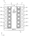
도 1은, 처리 시스템(10)의 일례를 나타내는 도면이다. 도 1은, 상측으로부터 본 처리 시스템(10)을 모식적으로 나타내고 있다. 본 실시형태에서의 처리 시스템(10)은, 예컨대 도 1에 나타낸 바와 같이, LM(Loader Module)(11), 반송실(12) 및 복수의 처리 유닛(20-1∼20-12)을 구비한다. 처리 시스템(10)은, 예컨대 클린룸 내에 설치된다. 또, 이하에서는, 복수의 처리 유닛(20-1∼20-12) 각각을 구별하지 않고 총칭하는 경우에 처리 유닛(20)으로 기재한다. 또한, 도 1에서는, 12대의 처리 유닛(20)을 갖는 처리 시스템(10)이 예시되어 있지만, 처리 시스템(10)에는, 11대 이하의 처리 유닛(20)이 설치되어도 좋고, 13대 이상의 처리 유닛(20)이 설치되어도 좋다. Fig. 1 is a diagram showing an example of the
LM(11)의 정면측(도 1의 상측)에는 복수의 포트가 설치되고, 각각의 포트에는, 오퍼레이터나 카세트 반송 시스템에 의해, 미처리 기판(W)이 수납된 카세트가 셋팅된다. 미처리 기판(W)은 피처리체의 일례이다. LM(11)의 배면측에는, 반송실(12) 및 복수의 처리 유닛(20)이 배치된다. 도 1의 예에서, 복수의 처리 유닛(20)은, 반송실(12)을 사이에 두고 가로 방향(예컨대 도 1에 나타낸 x축 방향)으로 2열로 배치되고, 각각의 열에서는, 가로 방향(예컨대 도 1에 나타낸 y축 방향)으로 6대의 처리 유닛(20)이 배치되어 있다. 처리 시스템(10)의 배면측에는 전원 유닛(14)이 배치된다. A plurality of ports are provided on the front side (upper side in Fig. 1) of the
각각의 처리 유닛(20)에는 복수의 처리 챔버가 배치된다. 전원 유닛(14)은, 각각의 처리 챔버에 소정 주파수의 고주파 전력을 공급한다. A plurality of processing chambers are disposed in each of the
반송실(12) 내에는, 이동식의 로보트 아암 등의 반송 장치(13)가 설치된다. 반송 장치(13)는, LM(11)의 포트에 셋팅된 카세트로부터 미처리 기판(W)을 꺼낸다. 그리고, 반송 장치(13)는, 반송실(12) 내를 이동하여, 카세트로부터 꺼낸 기판(W)을, 어느 처리 유닛(20) 내의 처리 챔버로 반송한다. 그리고, 처리 챔버에 있어서 처리가 행해진 기판(W)은, 반송 장치(13)에 의해 처리 챔버로부터 꺼내어져, LM(11)의 포트에 셋팅된 카세트로 복귀된다. In the
[처리 유닛(20)의 구성][Configuration of Processing Unit 20]
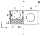
도 2는, 처리 유닛(20)의 일례를 나타내는 도면이다. 도 3은, 도 2의 A 방향에서 본 처리 유닛(20)의 일례를 나타내는 도면이다. 도 4는, 도 2의 B 방향에서 본 처리 유닛(20)의 일례를 나타내는 도면이다. Fig. 2 is a diagram showing an example of the
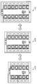
처리 유닛(20)은, 예컨대 도 3 및 도 4에 나타낸 바와 같이, 복수의 처리 챔버(22-1∼22-4)를 갖는다. 또, 이하에서는, 복수의 처리 챔버(22-1∼22-4) 각각을 구별하지 않고 총칭하는 경우에 처리 챔버(22)로 기재한다. 복수의 처리 챔버(22-1∼22-4)는, 상하 방향(예컨대 도 3 및 도 4에 나타낸 z축 방향)으로 중복되게 배치된다. 도 3 및 도 4에 예시한 처리 유닛(20)에서는, 4대의 처리 챔버(22-1∼22-4)가 중복되게 배치되어 있지만, 3대 이하의 처리 챔버(22)가 중복되게 배치되어도 좋고, 5대 이상의 처리 챔버(22)가 중복되게 배치되어도 좋다. 본 실시형태에 있어서, 처리 유닛(20)이 갖는 처리 챔버(22)의 대수는 짝수이다. The
각각의 처리 챔버(22)는, 정합기(220), 샤워 헤드(221) 및 배치대(222)를 갖는다. 정합기(220)는, 고주파 전원의 출력 임피던스와 부하 임피던스를 정합시키는 회로이다. 샤워 헤드(221)는, 후술하는 유량 제어부(31)로부터 공급된 처리 가스를 처리 챔버(22) 내에 공급한다. 샤워 헤드(221)에는, 정합기(220)를 통해 공급된 소정 주파수의 고주파 전력이 인가된다. 샤워 헤드(221)는, 배치대(222)에 대하여 상부 전극으로서 기능한다. 배치대(222)에는, 상면에 처리 대상의 기판(W)을 배치한다. 또한, 배치대(222)는, 샤워 헤드(221)에 대한 하부 전극으로서 기능한다. Each of the
각각의 처리 챔버(22)에는, 예컨대 도 2 및 도 4에 나타낸 바와 같이, z축 방향으로 서로 인접하는 LLM(Load Lock Module)(21-1∼21-4)이 배치된다. 또, 이하에서는, 복수의 LLM(21-1∼21-4) 각각을 구별하지 않고 총칭하는 경우에 LLM(21)로 기재한다. 각각의 LLM(21)은, 게이트 밸브(210), 반송 장치(211) 및 게이트 밸브(212)를 갖는다. LLMs (Load Lock Modules) 21-1 to 21-4, which are adjacent to each other in the z-axis direction, are disposed in each of the
상하 방향으로 인접하는 처리 챔버(22)들 사이에는, 예컨대 도 3 및 도 4에 나타낸 바와 같이, 유틸리티 모듈(30)이 배치된다. 본 실시형태의 처리 유닛(20)에서는, n(n은 짝수)대의 처리 챔버(22)가 상하 방향으로 중복되게 배치되어 있고, 유틸리티 모듈(30)은, 위로부터 n/2번째의 처리 챔버와 위로부터 (n/2)+1번째의 처리 챔버 사이에 배치된다. 도 3 및 도 4에 예시한 처리 유닛(20)에서는, 4대의 처리 챔버(22)가 상하 방향으로 중복되게 배치되어 있고, 유틸리티 모듈(30)은, 위로부터 2번째의 처리 챔버와 위로부터 3번째의 처리 챔버 사이에 배치되어 있다. Between the vertically
유틸리티 모듈(30)은, 유량 제어부(31) 및 배기 밸브(32)를 갖는다. 유량 제어부(31)는, 가스 공급원(40)으로부터 공급된 처리 가스의 유량을 소정의 유량으로 제어하고, 유량이 제어된 처리 가스를, 배관(230)을 통해 각 처리 챔버(22)에 공급한다. 유량 제어부(31)는, 가스 공급원(40)으로부터 공급된 클리닝 가스의 유량을 소정의 유량으로 제어하고, 배관(230)을 통해 각 처리 챔버(22)에 공급해도 좋다. 배관(230)은, 제1 배관의 일례이다. 배기 밸브(32)는, 배관(231)을 통해 각 처리 챔버(22)에 접속되고, 배관(232)을 통해 터보 분자 펌프 등의 배기 장치(41)에 접속된다. 그리고, 배기 밸브(32)는, 배기 장치(41)에 의해 각 처리 챔버(22)로부터 배기되는 가스의 배기량을 제어한다. 배관(231)은, 제2 배관의 일례이다. 배기 밸브(32)는, 배기 제어부의 일례이다. The
본 실시형태에 있어서, 유량 제어부(31)로부터 각 처리 챔버(22)까지의 배관(230)의 길이는, 처리 유닛(20) 내의 모든 처리 챔버(22)들 간에 동일하다. 이에 따라, 하나의 유량 제어부(31)에 의해 처리 가스의 유량을 제어하는 경우라 하더라도, 각 처리 챔버(22)에 공급되는 처리 가스의 유량의 차를 작게 할 수 있다. 이에 따라, 하나의 유량 제어부(31)를 통해, 복수의 처리 챔버(22)에 공급되는 처리 가스의 유량을 정밀하게 제어할 수 있다. 이 때문에, 각 처리 챔버(22)에 개별적으로 유량 제어부(31)를 설치할 필요가 없어져, 처리 유닛(20)의 소형화 및 비용의 절감이 가능해진다. The length of the piping 230 from the flow
또한, 본 실시형태에 있어서, 각 처리 챔버(22)로부터 배기 밸브(32)까지의 배관(231)의 길이는, 처리 유닛(20) 내의 모든 처리 챔버(22)들 간에 동일하다. 이에 따라, 하나의 배기 밸브(32)에 의해 가스의 배기량을 제어하는 경우라 하더라도, 각 처리 챔버(22)로부터 배기되는 가스의 배기량의 차를 작게 할 수 있다. 이에 따라, 하나의 배기 밸브(32)를 통해, 복수의 처리 챔버(22)로부터 배기되는 가스의 배기량을 정밀하게 제어할 수 있다. 이 때문에, 각 처리 챔버(22)에 개별적으로 배기 밸브(32)를 설치할 필요가 없어져, 처리 유닛(20)의 소형화 및 비용의 절감이 가능해진다. In this embodiment, the length of the
또한, 본 실시형태에 있어서, 유틸리티 모듈(30)은, 예컨대 도 3 및 도 4에 나타낸 바와 같이, 상하 방향에 있어서 처리 유닛(20)의 대략 중앙에 배치된다. 이에 따라, 유틸리티 모듈(30) 내의 유량 제어부(31)로부터 각 처리 챔버(22)에 접속되는 배관(230), 및 각 처리 챔버(22)로부터 유틸리티 모듈(30) 내의 배기 밸브(32)에 접속되는 배관(231)의 길이를 짧게 할 수 있다. 이에 따라, 배관(230) 및 배관(231)의 컨덕턴스를 크게 할 수 있어, 각 처리 챔버(22) 내의 압력 제어가 용이하게 된다. 또한, 처리 유닛(20)의 소형화 및 비용의 절감도 가능해진다. In this embodiment, the
또한, 예컨대 도 2에 나타낸 바와 같이, LLM(21)로부터 처리 챔버(22)로 향하는 방향(예컨대 도 2의 x축 방향)에 있어서, LLM(21)의 폭 L1은, LLM(21)에 인접하게 배치된 처리 챔버(22)의 폭 L2보다 좁다. 이 때문에, 인접하는 처리 유닛(20)의 처리 챔버(22)를 인접하게 배치한 경우, 예컨대 도 2에 나타낸 바와 같이, LLM(21)가 배치된 쪽의 처리 챔버(22)의 측면 중, LLM(21)에 인접하지 않는 영역의 측면(223)과, LLM(21)의 측면 중, LLM(21)으로부터 처리 챔버(22)로 향하는 방향으로 연장되는 측면(213)으로 둘러싸인 간극(23)이 형성된다. 그 간극(23)에는, 배관(230) 및 배관(231)이 배치된다. 2, in the direction from the
처리 챔버(22)에 있어서 기판(W)이 처리되는 경우에는, LLM(21)의 게이트 밸브(212)가 개방되고, 반송 장치(13)에 의해 미처리 기판(W)이 LLM(21) 내의 반송 장치(211) 상에 배치된다. 그리고, 게이트 밸브(212)가 폐쇄되고, LLM(21) 내부가 감압된다. 그리고, 게이트 밸브(210)가 개방되고, 반송 장치(211)에 의해 미처리 기판(W)이 처리 챔버(22) 내에 반입되어, 배치대(222) 상에 배치된다. 그리고, 다시 게이트 밸브(210)가 폐쇄된다. When the substrate W is processed in the
다음으로, 유량 제어부(31)에 의해, 유량이 조절된 처리 가스가 각 처리 챔버(22)에 공급된다. 유량 제어부(31)로부터 공급된 처리 가스는, 샤워 헤드(221)로부터 처리 챔버(22) 내에 공급된다. 그리고, 배기 밸브(32)에 의해 각 처리 챔버(22)의 배기량이 제어되고, 처리 챔버(22) 내부가 소정의 압력으로 제어된다. 그리고, 정합기(220)를 통해 샤워 헤드(221)에 소정 주파수의 고주파 전력이 인가되는 것에 의해, 처리 챔버(22) 내에 처리 가스의 플라즈마가 생성되고, 생성된 플라즈마에 의해, 배치대(222) 상에 배치된 기판(W)에 에칭이나 성막 등의 소정의 처리가 실시된다. Next, the process gas whose flow rate is adjusted is supplied to each
기판(W)에 대한 처리가 종료된 경우, 게이트 밸브(210)가 개방되고, 반송 장치(211)에 의해, 처리 후 기판(W)이 처리 챔버(22)로부터 반출된다. 그리고, 게이트 밸브(210)가 폐쇄되고, LLM(21) 내의 압력이 대기압으로 복귀된다. 그리고, 게이트 밸브(212)가 개방되고, 반송 장치(13)에 의해 처리 후 기판(W)이 LLM(21)로부터 반출된다. When the processing for the substrate W is completed, the
또, 본 실시형태의 처리 시스템(10)은, 처리 유닛(20) 단위로 증감이 가능하다. 예컨대, 도 5에 나타낸 바와 같이, 12개의 처리 유닛(20)을 갖는 처리 시스템(10-2)에 있어서, y축 방향으로 처리 유닛(20)을 늘리는 것에 의해, 예컨대 14개의 처리 유닛(20)을 갖는 처리 시스템(10-1)을 구성할 수 있다. 또한, 예컨대, 도 5에 나타낸 바와 같이, 12개의 처리 유닛(20)을 갖는 처리 시스템(10-2)에 있어서, y축 방향으로 처리 유닛(20)을 줄이는 것에 의해, 예컨대 10개의 처리 유닛(20)을 갖는 처리 시스템(10-3)을 구성할 수 있다. 이와 같이, 복수의 처리 챔버(22)가 중복되어 배치된 처리 유닛(20) 단위에서의 증설이나 감축이 가능하므로, 설치 장소의 면적이나 필요한 처리 능력에 따라서, 보다 높은 자유도로 처리 유닛(20)을 구성할 수 있다. The
또한, 처리 유닛(20)이 갖는 복수의 처리 챔버(22)는, 유량 제어부(31)를 통해 공급되는 처리 가스가 공통이므로, 처리 대상의 기판(W)에 대하여 동일한 처리를 행한다. 그러나, 별개의 처리 유닛(20)이 갖는 처리 챔버(22)끼리에서는, 처리 대상의 기판(W)에 대하여 상이한 처리가 행해져도 좋다. 예컨대, 도 1에 예시한 처리 시스템(10)에 있어서, 처리 유닛(20-1∼20-6)에서는 성막 처리가 행해지고, 처리 유닛(20-7∼20-12)에서는 에칭 처리가 행해져도 좋다. 또한, 처리 시스템(10)에는, 세정 장치, 열처리 장치, 코터/디벨로퍼 등, 대기압 환경 하에 행해지는 처리를 행하는 장치가 포함되어 있어도 좋다. The plurality of
이상, 일 실시형태에 관해 설명했다. 이상의 설명에서 분명한 바와 같이, 본 실시형태의 처리 시스템(10)에 의하면, 처리 시스템(10) 전체의 점유 면적을 줄일 수 있다. The embodiment has been described above. As is apparent from the above description, according to the
또, 개시한 기술은, 상기 실시형태에 한정되는 것이 아니라, 그 요지의 범위 내에서 수많은 변형이 가능하다. The disclosed technique is not limited to the above-described embodiment, but can be modified in many ways within the scope of the gist of the invention.
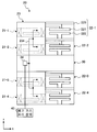
예컨대, 상기 실시형태에 있어서, 각 처리 유닛(20)이 갖는 처리 챔버(22)는, 유량 제어부(31)를 통해 공급된 처리 가스와 정합기(220)를 통해 공급된 고주파 전력을 이용하여 플라즈마를 생성하지만, 개시한 기술은 이것에 한정되지 않는다. 예컨대 도 6에 나타낸 바와 같이, 유틸리티 모듈(30) 내에 설치된 리모트 플라즈마 생성부(33)에 의해 플라즈마를 생성하고, 생성된 플라즈마 중의 라디칼이, 배관(233)을 통해 각 처리 챔버(22)에 공급되고, 각 처리 챔버(22) 내의 샤워 헤드(221)로부터 처리 챔버(22) 내에 공급되어도 좋다. 배관(233)은, 제3 배관의 일례이다. For example, in the above-described embodiment, the
또, 도 6에 나타낸 처리 유닛(20)에 있어서도, 리모트 플라즈마 생성부(33)로부터 각 처리 챔버(22)까지의 배관(233)의 길이는, 처리 유닛(20) 내의 모든 처리 챔버(22)들 간에 동일하다. 이에 따라, 하나의 리모트 플라즈마 생성부(33)에 의해 플라즈마가 생성된 경우라 하더라도, 각 처리 챔버(22)에 대한 라디칼의 공급량의 차를 작게 할 수 있다. 이에 따라, 하나의 리모트 플라즈마 생성부(33)로부터 각 처리 챔버(22)에 공급되는 라디칼의 양을 정밀하게 제어할 수 있다. 이 때문에, 각 처리 챔버(22)에서 개별적으로 플라즈마를 생성할 필요가 없어져, 처리 유닛(20)의 소형화 및 비용의 절감이 가능해진다. 6, the length of the piping 233 from the
또한, 예컨대 도 7에 나타낸 바와 같이, 각 LLM(21)을 감압하기 위한 배기 펌프(34)를 유틸리티 모듈(30) 내에 하나 설치하고, 배관(234)을 통해 각 LLM(21) 내의 가스를 배기하도록 해도 좋다. 배기 펌프(34)에 의해 각 LLM(21)으로부터 배기된 가스는, 배기 가스 처리 장치(42)로 보내진다. 또, 도 7에서는, 각 처리 챔버(22)로의 처리 가스의 공급로, 및 각 처리 챔버(22)로부터 배기되는 가스의 배기로는 생략되어 있다. 7, an
도 7의 예에서는, 1대의 배기 펌프(34)에 의해 처리 유닛(20) 내의 복수의 LLM(21)를 감압할 수 있기 때문에, LLM(21)마다 배기 펌프(34)를 설치하는 경우에 비교해서, 처리 유닛(20)의 소형화 및 비용의 절감이 가능해진다. 또한, 도 7에 나타낸 처리 유닛(20)에 있어서도, 각 LLM(21)으로부터 배기 펌프(34)까지의 배관(234)의 길이는, 처리 유닛(20) 내의 모든 LLM(21) 사이에서 동일한 것이 바람직하다. 이에 따라, 처리 유닛(20) 내의 복수의 LLM(21)에 있어서, 대기압으로부터 소정의 진공도로 감압되기까지의 시간차를 작게 할 수 있다. 이에 따라, 처리 시간을 단축시킬 수 있다. 또한, 도 7에 나타낸 처리 유닛(20)에 있어서도, 각 LLM(21)으로부터 배기 펌프(34)까지의 배관(234)은, 도 2에 나타낸 바와 같이, LLM(21)의 측면(213)과, 처리 챔버(22)의 측면(223)으로 둘러싸인 간극(23)에 배치되는 것이 바람직하다. 7, since a plurality of
또한, 상기 실시형태에서의 처리 유닛(20)에서는, n(n은 짝수)대의 처리 챔버(22)가 상하 방향으로 중복되게 배치되고, 위로부터 n/2번째의 처리 챔버(22)와, 위로부터 (n/2)+1번째의 처리 챔버(22)의 사이에 유틸리티 모듈(30)이 배치되지만, 개시한 기술은 이것에 한정되지 않는다. 예컨대, 유틸리티 모듈(30)은, 최상단의 처리 챔버(22)의 위, 최하단의 처리 챔버(22)의 아래, 혹은, 상하 방향으로 인접하는 어느 2개의 처리 챔버(22) 사이에 배치되어도 좋다. 다만, 이 경우에도, 유틸리티 모듈(30) 내의 유량 제어부(31)로부터 각 처리 챔버(22)에 접속되는 배관(230)이나, 각 처리 챔버(22)로부터 배기 밸브(32)에 접속되는 배관(231)이, 처리 유닛(20) 내의 모든 처리 챔버(22)들 간에 동일한 길이인 것이 바람직하다. In the
이상, 실시형태를 이용하여 본 발명을 설명했지만, 본 발명의 기술적 범위는 상기 실시형태에 기재된 범위로 한정되지 않는다. 상기 실시형태에 대한 다양한 변경 또는 개량을 가하는 것이 가능한 것은 당업자에게는 분명하다. 또한, 그와 같은 변경 또는 개량을 가한 형태도 본 발명의 기술적 범위에 포함될 수 있는 것은, 청구범위의 기재로부터 분명하다. While the present invention has been described with reference to the embodiment, the technical scope of the present invention is not limited to the scope described in the above embodiment. It will be apparent to those skilled in the art that various changes or modifications can be made to the embodiments described above. It is apparent from the description of the claims that the form of such modification or improvement can be included in the technical scope of the present invention.
10 : 처리 시스템
11 : LM
12 : 반송실
13 : 반송 장치
14 : 전원 유닛
20 : 처리 유닛
21 : LLM
210 : 게이트 밸브
211 : 반송 장치
212 : 게이트 밸브
22 : 처리 챔버
220 : 정합기
221 : 샤워 헤드
222 : 배치대
23 : 간극
230 : 배관
231 : 배관
232 : 배관
233 : 배관
234 : 배관
30 : 유틸리티 모듈
31 : 유량 제어부
32 : 배기 밸브
33 : 리모트 플라즈마 생성부
34 : 배기 펌프
40 : 가스 공급원
41 : 배기 장치
42 : 배기 가스 처리 장치10: Processing system
11: LM
12: Carrier
13:
14: Power supply unit
20: processing unit
21: LLM
210: Gate valve
211:
212: Gate valve
22: Processing chamber
220: Matching machine
221: Shower head
222:
23: Clearance
230: Piping
231: Piping
232: Piping
233: Piping
234: Piping
30: Utility module
31:
32: Exhaust valve
33: Remote plasma generation unit
34: Exhaust pump
40: gas supply source
41: Exhaust system
42: Exhaust gas treatment device
Claims (11)
을 구비하는 처리 시스템으로서, 각각의 상기 처리 유닛은,
공급된 처리 가스를 이용하여 피처리체를 처리하는 복수의 처리 챔버와,
상기 복수의 처리 챔버 각각에 공급되는 상기 처리 가스의 유량을 제어하는 유량 제어부를 포함하는 유틸리티 모듈
을 가지며,
상기 복수의 처리 챔버는, 상하 방향으로 중복되게 배치되고,
상기 유틸리티 모듈은, 상기 복수의 처리 챔버 중, 상하 방향으로 인접하는 2개의 처리 챔버 사이에 배치되는 것을 특징으로 하는 처리 시스템. One or more processing units
Wherein each of the processing units comprises:
A plurality of processing chambers for processing the object to be processed using the supplied processing gas,
And a flow control unit for controlling a flow rate of the process gas supplied to each of the plurality of process chambers
Lt; / RTI >
Wherein the plurality of processing chambers are arranged to overlap in the vertical direction,
Wherein the utility module is disposed between two vertically adjacent processing chambers among the plurality of processing chambers.
각각의 상기 처리 유닛은, 상기 유량 제어부로부터 상기 복수의 처리 챔버 각각에 분배되는 상기 처리 가스가 유통하는 제1 배관을 가지며,
상기 유량 제어부로부터 상기 복수의 처리 챔버 각각으로의 상기 제1 배관의 길이는, 상기 처리 유닛 내의 상기 복수의 처리 챔버들 간에 동일한 것을 특징으로 하는 처리 시스템. The method according to claim 1,
Wherein each of the processing units has a first pipe through which the process gas distributed to each of the plurality of process chambers from the flow control unit flows,
Wherein the length of the first pipe from the flow control unit to each of the plurality of processing chambers is the same between the plurality of processing chambers in the processing unit.
각각의 상기 처리 유닛은, 상기 처리 챔버마다, 상기 처리 챔버에 인접하게 배치된 로드록 모듈(load lock module)을 가지며,
상기 로드록 모듈로부터 상기 처리 챔버로 향하는 방향에 있어서, 상기 로드록 모듈의 폭은, 상기 로드록 모듈에 인접하게 배치된 상기 처리 챔버의 폭보다 좁고,
상기 제1 배관은, 상기 로드록 모듈이 배치된 쪽의 상기 처리 챔버의 측면 중, 상기 로드록 모듈에 인접하지 않는 영역의 측면과, 상기 로드록 모듈의 측면 중, 상기 로드록 모듈로부터 상기 처리 챔버로 향하는 방향으로 연장되는 측면으로 형성된 간극에 배치되는 것을 특징으로 하는 처리 시스템. 3. The method of claim 2,
Each said processing unit having, for each of said processing chambers, a load lock module disposed adjacent said processing chamber,
In a direction from the load lock module toward the process chamber, the width of the load lock module is narrower than the width of the process chamber disposed adjacent the load lock module,
Wherein the first pipe includes a side surface of a side of the processing chamber on a side where the load lock module is disposed and a side of an area not adjacent to the load lock module and a side surface of the side surface of the load lock module, And a side wall extending in a direction toward the chamber.
상기 유틸리티 모듈은, 상기 처리 유닛이 갖는 상기 복수의 처리 챔버 각각으로부터 배기되는 가스의 배기량을 제어하는 배기 제어부를 더 갖는 것을 특징으로 하는 처리 시스템. The method according to claim 1,
Wherein the utility module further comprises an exhaust control part for controlling exhaust amount of gas exhausted from each of the plurality of processing chambers of the processing unit.
각각의 상기 처리 유닛은, 상기 복수의 처리 챔버 각각으로부터 배기되는 가스가 유통하는 제2 배관을 가지며,
상기 복수의 처리 챔버 각각으로부터 상기 배기 제어부까지의 상기 제2 배관의 길이는, 상기 처리 유닛 내의 상기 복수의 처리 챔버들 간에 동일한 것을 특징으로 하는 처리 시스템. 5. The method of claim 4,
Each of said processing units has a second pipe through which gas exhausted from each of said plurality of processing chambers flows,
Wherein the length of the second piping from each of the plurality of processing chambers to the exhaust control part is the same between the plurality of processing chambers in the processing unit.
상기 처리 유닛은, 상기 처리 챔버마다, 상기 처리 챔버에 인접하게 배치된 로드록 모듈을 가지며,
상기 로드록 모듈로부터 상기 처리 챔버로 향하는 방향에 있어서, 상기 로드록 모듈의 폭은, 상기 로드록 모듈에 인접하게 배치된 상기 처리 챔버의 폭보다 좁고,
상기 제2 배관은, 상기 로드록 모듈이 배치된 쪽의 상기 처리 챔버의 측면 중, 상기 로드록 모듈에 인접하지 않는 영역의 측면과, 상기 로드록 모듈의 측면 중, 상기 로드록 모듈로부터 상기 처리 챔버로 향하는 방향으로 연장되는 측면으로 형성된 간극에 배치되는 것을 특징으로 하는 처리 시스템. 6. The method of claim 5,
Wherein the processing unit has, for each of the processing chambers, a load lock module disposed adjacent to the processing chamber,
In a direction from the load lock module toward the process chamber, the width of the load lock module is narrower than the width of the process chamber disposed adjacent the load lock module,
Wherein the second piping comprises a side surface of a side of the processing chamber on a side where the load lock module is disposed and a side of an area not adjacent to the load lock module and a side surface of the side surface of the load lock module, And a side wall extending in a direction toward the chamber.
상기 유틸리티 모듈은, 플라즈마를 생성하고, 생성된 플라즈마 중의 라디칼을, 상기 처리 유닛이 갖는 상기 복수의 처리 챔버 각각에 공급하는 리모트 플라즈마 생성부를 더 갖는 것을 특징으로 하는 처리 시스템. The method according to claim 1,
Wherein the utility module further comprises a remote plasma generator for generating a plasma and supplying radicals in the generated plasma to each of the plurality of processing chambers of the processing unit.
각각의 상기 처리 유닛은, 상기 리모트 플라즈마 생성부에 의해 생성되고, 상기 복수의 처리 챔버 각각에 분배되는 라디칼이 유통하는 제3 배관을 가지며,
상기 복수의 처리 챔버 각각으로부터 상기 리모트 플라즈마 생성부까지의 상기 제3 배관의 길이는, 상기 처리 유닛 내의 상기 복수의 처리 챔버들 간에 동일한 것을 특징으로 하는 처리 시스템. 8. The method of claim 7,
Each of said processing units has a third pipe generated by said remote plasma generating unit and through which the radicals distributed to each of said plurality of processing chambers flow,
Wherein the length of the third piping from each of the plurality of processing chambers to the remote plasma generating unit is the same among the plurality of processing chambers in the processing unit.
각각의 상기 처리 유닛은, 상기 처리 챔버마다, 상기 처리 챔버에 인접하게 배치된 로드록 모듈을 가지며,
상기 로드록 모듈로부터 상기 처리 챔버로 향하는 방향에 있어서, 상기 로드록 모듈의 폭은, 상기 로드록 모듈에 인접하게 배치된 상기 처리 챔버의 폭보다 좁고,
상기 제3 배관은, 상기 로드록 모듈이 배치된 쪽의 상기 처리 챔버의 측면 중, 상기 로드록 모듈에 인접하지 않는 영역의 측면과, 상기 로드록 모듈의 측면 중, 상기 로드록 모듈로부터 상기 처리 챔버로 향하는 방향으로 연장되는 측면으로 형성된 간극에 배치되는 것을 특징으로 하는 처리 시스템. 9. The method of claim 8,
Each said processing unit having, for each of said processing chambers, a load lock module disposed adjacent said processing chamber,
In a direction from the load lock module toward the process chamber, the width of the load lock module is narrower than the width of the process chamber disposed adjacent the load lock module,
Wherein the third piping includes a side surface of a side of the processing chamber on a side where the load lock module is disposed and a side of an area not adjacent to the load lock module, And a side wall extending in a direction toward the chamber.
상기 유틸리티 모듈은, 상기 처리 유닛이 갖는 상기 복수의 처리 챔버의 수를 n으로 한 경우에, 위로부터 n/2번째의 처리 챔버와 위로부터 (n/2)+1번째의 처리 챔버 사이에 배치되는 것을 특징으로 하는 처리 시스템. The apparatus according to claim 1, wherein the number of the plurality of processing chambers of each of the processing units is an even number of 2 or more,
The utility module is arranged between the (n / 2) -th processing chamber and the (n / 2) + 1 -th processing chamber from the top to the top of the n / 2-th processing chamber when the number of the plurality of processing chambers of the processing unit is n Wherein the processing system comprises:
Applications Claiming Priority (3)
| Application Number | Priority Date | Filing Date | Title |
|---|---|---|---|
| JP2015103896A JP6463220B2 (en) | 2015-05-21 | 2015-05-21 | Processing system |
| JPJP-P-2015-103896 | 2015-05-21 | ||
| PCT/JP2016/064066 WO2016185984A1 (en) | 2015-05-21 | 2016-05-11 | Treatment system |
Publications (2)
| Publication Number | Publication Date |
|---|---|
| KR20170137196A true KR20170137196A (en) | 2017-12-12 |
| KR102110021B1 KR102110021B1 (en) | 2020-05-12 |
Family
ID=57320141
Family Applications (1)
| Application Number | Title | Priority Date | Filing Date |
|---|---|---|---|
| KR1020177033083A KR102110021B1 (en) | 2015-05-21 | 2016-05-11 | Processing system |
Country Status (6)
| Country | Link |
|---|---|
| US (1) | US20180130681A1 (en) |
| JP (1) | JP6463220B2 (en) |
| KR (1) | KR102110021B1 (en) |
| CN (1) | CN107615446B (en) |
| TW (1) | TWI698551B (en) |
| WO (1) | WO2016185984A1 (en) |
Cited By (1)
| Publication number | Priority date | Publication date | Assignee | Title |
|---|---|---|---|---|
| US11387127B2 (en) | 2019-07-17 | 2022-07-12 | Semes Co., Ltd. | Substrate treating apparatus and substrate transfer apparatus |
Families Citing this family (2)
| Publication number | Priority date | Publication date | Assignee | Title |
|---|---|---|---|---|
| JP6844263B2 (en) * | 2017-01-05 | 2021-03-17 | 東京エレクトロン株式会社 | Board processing equipment |
| GB201718752D0 (en) | 2017-11-13 | 2017-12-27 | Edwards Ltd | Vacuum and abatement systems |
Citations (2)
| Publication number | Priority date | Publication date | Assignee | Title |
|---|---|---|---|---|
| JPH10229111A (en) * | 1997-02-18 | 1998-08-25 | Hitachi Ltd | Semiconductor manufacturing device |
| JP2000223425A (en) | 1999-02-02 | 2000-08-11 | Nec Corp | Substrate-processing device, gas-feeding method, and laser beam feeding method |
Family Cites Families (16)
| Publication number | Priority date | Publication date | Assignee | Title |
|---|---|---|---|---|
| JPS6063374A (en) * | 1983-09-14 | 1985-04-11 | Canon Inc | Apparatus for producing deposited film by vapor phase method |
| US6176667B1 (en) * | 1996-04-30 | 2001-01-23 | Applied Materials, Inc. | Multideck wafer processing system |
| KR100269097B1 (en) * | 1996-08-05 | 2000-12-01 | 엔도 마코토 | Wafer process apparatus |
| US6835278B2 (en) * | 2000-07-07 | 2004-12-28 | Mattson Technology Inc. | Systems and methods for remote plasma clean |
| US6630053B2 (en) * | 2000-08-22 | 2003-10-07 | Asm Japan K.K. | Semiconductor processing module and apparatus |
| US20030045098A1 (en) * | 2001-08-31 | 2003-03-06 | Applied Materials, Inc. | Method and apparatus for processing a wafer |
| US6913652B2 (en) * | 2002-06-17 | 2005-07-05 | Applied Materials, Inc. | Gas flow division in a wafer processing system having multiple chambers |
| JP5025609B2 (en) * | 2003-09-04 | 2012-09-12 | 株式会社日立ハイテクノロジーズ | Vacuum processing equipment |
| US20060104799A1 (en) * | 2004-07-12 | 2006-05-18 | Applied Materials, Inc. | Methods and apparatus for reducing an electronic device manufacturing tool footprint |
| JP2009105081A (en) * | 2007-10-19 | 2009-05-14 | Ebatekku:Kk | Substrate processing apparatus |
| JP5260981B2 (en) * | 2008-02-22 | 2013-08-14 | 株式会社日立ハイテクノロジーズ | Vacuum processing equipment |
| JP2011077399A (en) * | 2009-09-30 | 2011-04-14 | Tokyo Electron Ltd | Method for transferring subject to be processed and apparatus for processing subject to be processed |
| TWI719331B (en) * | 2011-10-26 | 2021-02-21 | 美商布魯克斯自動機械公司 | Substrate processing system |
| US20150030766A1 (en) * | 2013-07-25 | 2015-01-29 | Novellus Systems, Inc. | Pedestal bottom clean for improved fluorine utilization and integrated symmetric foreline |
| JP2015035460A (en) * | 2013-08-08 | 2015-02-19 | 信越半導体株式会社 | Method of manufacturing epitaxial wafer |
| JP5977729B2 (en) * | 2013-11-14 | 2016-08-24 | 東京エレクトロン株式会社 | Substrate processing system |
-
2015
- 2015-05-21 JP JP2015103896A patent/JP6463220B2/en active Active
-
2016
- 2016-05-11 US US15/574,514 patent/US20180130681A1/en not_active Abandoned
- 2016-05-11 WO PCT/JP2016/064066 patent/WO2016185984A1/en active Application Filing
- 2016-05-11 KR KR1020177033083A patent/KR102110021B1/en active IP Right Grant
- 2016-05-11 CN CN201680029129.2A patent/CN107615446B/en active Active
- 2016-05-17 TW TW105115209A patent/TWI698551B/en not_active IP Right Cessation
Patent Citations (2)
| Publication number | Priority date | Publication date | Assignee | Title |
|---|---|---|---|---|
| JPH10229111A (en) * | 1997-02-18 | 1998-08-25 | Hitachi Ltd | Semiconductor manufacturing device |
| JP2000223425A (en) | 1999-02-02 | 2000-08-11 | Nec Corp | Substrate-processing device, gas-feeding method, and laser beam feeding method |
Cited By (1)
| Publication number | Priority date | Publication date | Assignee | Title |
|---|---|---|---|---|
| US11387127B2 (en) | 2019-07-17 | 2022-07-12 | Semes Co., Ltd. | Substrate treating apparatus and substrate transfer apparatus |
Also Published As
| Publication number | Publication date |
|---|---|
| JP2016219629A (en) | 2016-12-22 |
| CN107615446B (en) | 2020-12-04 |
| KR102110021B1 (en) | 2020-05-12 |
| TWI698551B (en) | 2020-07-11 |
| JP6463220B2 (en) | 2019-01-30 |
| US20180130681A1 (en) | 2018-05-10 |
| CN107615446A (en) | 2018-01-19 |
| TW201706450A (en) | 2017-02-16 |
| WO2016185984A1 (en) | 2016-11-24 |
Similar Documents
| Publication | Publication Date | Title |
|---|---|---|
| KR102073485B1 (en) | Processing apparatus and processing method | |
| TW201304039A (en) | Apparatus and mothod for treating substrate | |
| KR20170137196A (en) | Processing system | |
| TW201431444A (en) | Plasma treatment device and method | |
| US11282737B2 (en) | Moving substrate transfer chamber | |
| US20140261805A1 (en) | Gas distribution apparatus for directional and proportional delivery of process gas to a process chamber | |
| US11488810B2 (en) | Showerhead shroud | |
| TWI757969B (en) | Plasma enhanced anneal chamber for wafer outgassing | |
| KR102175089B1 (en) | Buffer unit, Apparatus and Method for treating substrate with the unit | |
| KR102125122B1 (en) | Substrate processing apparatus | |
| KR100743275B1 (en) | Plasma processing method and post-processing method | |
| KR101928008B1 (en) | Substrate treating apparatus and substrate treating method | |
| US20230085987A1 (en) | Linear arrangement for substrate processing tools | |
| JP7450159B2 (en) | Substrate processing equipment | |
| JP2024019926A (en) | Film forming equipment | |
| US20230245862A1 (en) | Delivery of high concentrations of molecular hydrogen and other gases to substrate processing systems | |
| KR102051978B1 (en) | Apparatus for processing substrate | |
| JP2022018902A (en) | Substrate processing system, maintenance method and substrate processing method | |
| JP5715210B2 (en) | Substrate processing method | |
| KR20180021337A (en) | Substrate treating apparatus and substrate treating method | |
| KR20130066169A (en) | Substrate processing method and substrate processing method | |
| KR20060066407A (en) | Semiconductor manufacturing equipment having unified vacuum pump |
Legal Events
| Date | Code | Title | Description |
|---|---|---|---|
| A201 | Request for examination | ||
| E902 | Notification of reason for refusal | ||
| E90F | Notification of reason for final refusal | ||
| E701 | Decision to grant or registration of patent right | ||
| GRNT | Written decision to grant |