KR20170131043A - Robot gantry system - Google Patents
Robot gantry system Download PDFInfo
- Publication number
- KR20170131043A KR20170131043A KR1020160062178A KR20160062178A KR20170131043A KR 20170131043 A KR20170131043 A KR 20170131043A KR 1020160062178 A KR1020160062178 A KR 1020160062178A KR 20160062178 A KR20160062178 A KR 20160062178A KR 20170131043 A KR20170131043 A KR 20170131043A
- Authority
- KR
- South Korea
- Prior art keywords
- guide rail
- roller
- main frame
- pinion
- rack
- Prior art date
Links
Images


Classifications
-
- B—PERFORMING OPERATIONS; TRANSPORTING
- B25—HAND TOOLS; PORTABLE POWER-DRIVEN TOOLS; MANIPULATORS
- B25J—MANIPULATORS; CHAMBERS PROVIDED WITH MANIPULATION DEVICES
- B25J9/00—Programme-controlled manipulators
- B25J9/02—Programme-controlled manipulators characterised by movement of the arms, e.g. cartesian coordinate type
- B25J9/023—Cartesian coordinate type
- B25J9/026—Gantry-type
-
- B—PERFORMING OPERATIONS; TRANSPORTING
- B25—HAND TOOLS; PORTABLE POWER-DRIVEN TOOLS; MANIPULATORS
- B25J—MANIPULATORS; CHAMBERS PROVIDED WITH MANIPULATION DEVICES
- B25J5/00—Manipulators mounted on wheels or on carriages
- B25J5/007—Manipulators mounted on wheels or on carriages mounted on wheels
-
- B—PERFORMING OPERATIONS; TRANSPORTING
- B25—HAND TOOLS; PORTABLE POWER-DRIVEN TOOLS; MANIPULATORS
- B25J—MANIPULATORS; CHAMBERS PROVIDED WITH MANIPULATION DEVICES
- B25J9/00—Programme-controlled manipulators
- B25J9/10—Programme-controlled manipulators characterised by positioning means for manipulator elements
- B25J9/102—Gears specially adapted therefor, e.g. reduction gears
-
- B—PERFORMING OPERATIONS; TRANSPORTING
- B25—HAND TOOLS; PORTABLE POWER-DRIVEN TOOLS; MANIPULATORS
- B25J—MANIPULATORS; CHAMBERS PROVIDED WITH MANIPULATION DEVICES
- B25J9/00—Programme-controlled manipulators
- B25J9/10—Programme-controlled manipulators characterised by positioning means for manipulator elements
- B25J9/12—Programme-controlled manipulators characterised by positioning means for manipulator elements electric
- B25J9/123—Linear actuators
Abstract
Description
본 발명은 로봇 겐트리 시스템에 대한 것으로, 구체적으로, 고속회전, 고하중용 롤러 및 헬리컬 기어, 비일치 연결부 정렬을 적용하여 저소음 및 저진동을 구현한 로봇 겐트리 시스템에 관한 것이다. The present invention relates to a robot gantry system, and more particularly, to a robot gantry system that realizes low noise and low vibration by applying a high-speed rotation, a high-load roller, a helical gear,
로봇 기술의 발전에 따라, 산업 현장에서도 다양한 산업용 로봇이 사용되고 있다. With the development of robotic technology, various industrial robots are used in the industrial field.
특히, 대형 제품에 대하여 보다 자유롭게 작업을 수행하기 위하여 다양한 겐트리 로봇이 사용되고 있다. In particular, various gantry robots have been used to perform tasks more freely for large products.
종래의 겐트리 로봇은 레일을 따라 움직이는 겐트리 부와, 겐트리 부에 매달려 겐트리 부를 따라 움직이며 작업을 수행하는 로봇 암 등을 포함할 수 있다. Conventional gantry robots can include a gantry part moving along a rail, and a robot arm moving along a gantry part hanging from a gantry part.
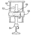
도 1은 종래의 겐트리 로봇을 보여주는 정면도이고, 도 2는 그 우측면도, 도 3은 도 2의 축결합되어 있는 새들(60)을 중점적으로 보여주는 도면이다.
FIG. 1 is a front view showing a conventional gantry robot, FIG. 2 is a right side view of the robot, and FIG. 3 is a view showing
겐트리 로봇(10)이 도 1의 중앙에 보여지고 있는데, 이 겐트리 로봇(10)은 상하로 이동가능 하게 된 리프터(12)를 구비하고 있고, 이 리프터(12)는 캐리지(Carriage)(14)에 볼트, 너트와 같은 결합부재로 결합되어 있다. 또한, 캐리지(14)는 거더(Girder)(50)에 결합 지지되어 겐트리 로봇(10)이 좌우로 이동될 수 있게 되어 있다.
The gantry robot 10 is shown in the center of Fig. 1. The gantry robot 10 has a
거더(50)는 또한, 새들(Saddle)(60)에 의해 양단이 접합 지지되어 있고, 이 새들(60)은 그 일단부가 바퀴(62)와 축결합되어 있다. 이러한 결합구조는 도 3을 보면 상세히 알 수 있다.
The
도 1 내지 도 3에서 보는 바와 같이, 새들(60)은 중공을 갖고 있고, 이 중공에는 안내레일(68) 상면에 접촉되어 있는 바퀴(62)가 위치하게 된다. 바퀴(62)는 그 중앙부가 축(68)으로 관통하여 새들(60)의 양측벽에 고착되게 된다. 게다가, 바퀴(62)가 관통되어 축(68)과 접하게 되는 부분에는 베어링과 같은 축받이부재(66)가 구성되어 있고, 이리하여, 바퀴(62)가 새들(60)에 고정되어 있는 축(68)에 구애됨이 없이, 마찰없이 구동될 수 있게 되는 것이다. 즉, 바퀴(62)는 안내레일(64) 상면에 접촉 위치하게 되어 겐트리 로봇(10)이 전후로 이동될 수 있게 된다. 이와같은 구조로 이루어진 장치의 구동은 주로 전동기와 같은 구동장치(20)가 각 필요한 장치에 연결되어 이루어지게 된다.
As shown in FIGS. 1 to 3, the
이에, 작업자는 필요한 때 전원이 인가되게 함으로써, 그 구동을 제어할 수 있게 되는 것이다. 따라서, 겐트리 로봇이 전후, 좌우는 물론 상하로 이동될 수 있게 되는 것이다. Thus, the operator can control the drive by applying power when necessary. Therefore, the gantry robot can move forward, backward, left and right as well as up and down.
그러나, 이러한 겐트리 로봇의 경우, 고속회전이나, 고하중에서는 소음 및 진동이 심하여 정밀한 작업에 사용되기 부적합 하였으며, 각 레일의 연결부에서 롤러로 전달되는 지속적인 진동 및 소음은 겐트리 로봇의 수명을 단축하는 문제점이 있었다. However, these gantry robots are not suitable for precise work because of high noise and vibration during high-speed rotation and under high load. Continuous vibration and noise transmitted from the connecting portion of each rail to the rollers shortens the life of the gantry robot .
KR 공개특허공보 10-2013-0051211 A KR Patent Publication No. 10-2013-0051211 A
KR 공개특허공보 10-2015-0071485 A KR Patent Publication No. 10-2015-0071485 A
KR 등록실용신안공보 20-0236719 Y1 KR Registration Utility Model Bulletin 20-0236719 Y1
본 발명은 상기와 같은 종래기술의 문제점을 해결하는 것을 목적으로 한다. SUMMARY OF THE INVENTION It is an object of the present invention to solve the above problems of the prior art.
구체적으로, 본 발명의 목적은, 고속회전, 고하중 시에도 저소음 저진동으로 정밀한 구동이 가능하도록 하는 로봇 겐트리 시스템을 제공할 수 있도록 하는 것이다. Specifically, an object of the present invention is to provide a robot gantry system that enables precise driving with low noise and low vibration even at high speed rotation and high load.
이러한 목적을 달성하기 위한 본 발명에 따른 로봇 겐트리 시스템은, 내부가 비어있는 사각 기둥형상의 메인 프레임(100); 상기 메인 프레임(100)의 양측면에 형성되고, 사각 기둥 형상의 가이드 레일(110); 상기 메인 프레임(100)의 상면에 형성되고, 일측면에 직선 기어를 형성하는 랙(120); 상기 각 가이드 레일(110)의 상면, 하면, 측면과 각각 접하여 가이드 레일(110)의 길이방향으로 회전이동하는 롤러(200); 상기 랙(120)의 기어와 맞물리는 치형을 형성하는 피니언(300); 상기 피니언(300)과 연결되고, 상기 피니언(300)에 회전구동력을 부여 하는 모터(400);를 포함하는 것을 특징으로 한다.
To achieve these and other advantages and in accordance with the purpose of the present invention, as embodied and broadly described herein, there is provided a robot gantry system comprising: a main frame having a square pillar shape;
이상과 같이 본 발명은 헬리컬 치형의 랙(120) 및 피니언(300)과 가이드 레일(110)의 3면과 접하는 롤러(200)로 인하여, 고속회전, 고하중 시에도 저소음 저진동으로 정밀한 구동이 가능하도록 하는 효과를 가진다.
As described above, according to the present invention, it is possible to perform precise driving with low noise and low vibration even at high speed rotation and high load due to the helical
도 1은 종래의 겐트리 로봇의 정면도이다;
도 2는 종래의 겐트리 로봇의 측면도이다;
도 3은 종래의 겐트리 로봇의 단면도이다;
도 4는 본 발명의 실시예에 따른 로봇 겐트리 시스템의 전체 구성도이다;
도 5는 본 발명의 실시예에 따른 로봇 겐트리 시스템의 평면도이다;
도 6은 본 발명의 실시예에 따른 로봇 겐트리 시스템의 정면도이다;1 is a front view of a conventional gantry robot;
2 is a side view of a conventional gantry robot;
3 is a cross-sectional view of a conventional gantry robot;
4 is an overall configuration diagram of a robot gantry system according to an embodiment of the present invention;
5 is a top view of a robot gantry system in accordance with an embodiment of the present invention;
6 is a front view of a robot gantry system according to an embodiment of the present invention;
이하에서는, 본 발명의 실시예에 따른 도면을 참조하여 설명하지만, 이는 본 발명의 더욱 용이한 이해를 위한 것으로, 본 발명의 범주가 그것에 의해 한정되는 것은 아니다. Hereinafter, embodiments of the present invention will be described with reference to the accompanying drawings, but the present invention is not limited by the scope of the present invention.
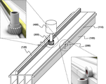
도 4를 참고하면, 본 발명에 따른 로봇 겐트리 시스템은, 내부가 비어있는 사각 기둥형상의 메인 프레임(100); 상기 메인 프레임(100)의 양측면에 형성되고, 사각 기둥 형상의 가이드 레일(110); 상기 메인 프레임(100)의 상면에 형성되고, 일측면에 직선 기어를 형성하는 랙(120); 상기 각 가이드 레일(110)의 상면, 하면, 측면과 각각 접하여 가이드 레일(110)의 길이방향으로 회전이동하는 롤러(200); 상기 랙(120)의 기어와 맞물리는 치형을 형성하는 피니언(300); 상기 피니언(300)과 연결되고, 상기 피니언(300)에 회전구동력을 부여 하는 모터(400);를 포함하는 것을 특징으로 한다.
Referring to FIG. 4, the robot gantry system according to the present invention includes a
구체적으로, 도 4에서 보는 바와 같이, 로봇 겐트리가 이동하는 가로 길이방향의 중공형 사각 기둥인 메인 프레임(100)의 경우, 하나이상의 중공형 사각 기둥을 측면이 상호 접합한 다중 기둥구조로서, 고하중을 견딜 수 있도록 구성하는 것이 바람직하며, 이외에도 메인 프레임(100)의 내부에 지지프레임을 내장하거나, 트러스 구조를 선택하여 구성할 수 있다.
Specifically, as shown in FIG. 4, in the case of the
다음으로, 이러한 메인 프레임(100)의 양측면에는, 가이드 레일(110)이 각각 형성되는데, 상기 가이드 레일(110)은 사각 기둥형상으로, 상기 메인 프레임(100)의 길이방향으로 연장되어 형상된다.
Next,
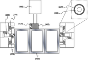
가이드 레일(110)의 상기 메인 프레임(100)과 결합한 측면을 제외한 나머지 3면에는 도 4에서 보는 바와 같이, 롤러(200)가 접하여 가이드 레일(110)의 3면을 압착하면서 길이방향으로 구동된다.
As shown in FIG. 4, the three sides of the
이러한 롤러(200)의 경우, 도 4 및 5에서 보는 바와 같이, 상기 가이드 레일(110)의 상면, 하면, 측면과 각각 접하는 3개의 롤러(200)가 하나의 롤러 모듈을 이루고, 각 롤러(200)가 별도의 회전축을 가지는 것으로써, 추가적으로, 상기 롤러(200)와 상기 가이드 레일(110)의 밀착을 위하여, 도 6에서 보는 바와 같이, 롤러(200)의 회전축에 롤러(200)가 상기 가이드 레일(110)의 접면과 밀착되도록 가이드 레일(110) 접면 방향으로 압착하는 스프링 구동부(210)를 구비할 수 있다.
4 and 5, the three
또한, 상기 롤러(200)는, 도 6에서와 같이, 상기 가이드 레일(110)과 접하는 면에 탄성력을 가진 신축소재를 적용한 쿠션링(220)을 형성할 수 있는데, 즉, 상기 스프링 구동부(210)와 쿠션링(220)으로 인하여, 상기 롤러(200)와 상기 가이드 레일(110)이 상호 밀착할 수 있으며, 상기 가이드 레일(110) 표면의 불균일 부분이나, 연결부위에 대한 충격을 겐트리 시스템에 전달하는 것을 방지하여 소음 저감 및 진동을 저감하는 효과를 가져온다.
6, the
다음으로, 상기 메인 프레임(100)의 상면에는, 일면에 길이방향으로 기어 치형을 형성한 랙(120)이 형성 되는데, 이러한 랙(120)에 도 4에서 보는 바와 같이, 랙(120)의 치형과 대응되는 치형을 형성한 피니언(300)이 치형 결합한다.
4, a
이러한 랙(120)과 피니언(300)의 치형은, 도 4에서 보는 바와 같이, 직선형의 기어형상이 아닌, 사선 형상의 헬리컬 기어(helical gear) 형상으로서, 접촉선의 길이가 길어 보다 큰 힘을 전달할 수 있고, 원활하게 회전하므로 저소음인 장점을 가진다.
As shown in FIG. 4, the teeth of the
헬리컬 기어의 형상에 대하여서는, 사선의 방향을 달리하여 좌 헬리컬 기어 또는 우 헬리컬 기어를 선택할 수 있으며, 2중 헬리컬 기어의 적용도 가능하다. As to the shape of the helical gear, a left helical gear or a right helical gear can be selected by changing the diagonal direction, and a double helical gear can also be applied.
다음으로, 상기 가이드 레일(110) 및 랙(120)은, 단일 가이드 레일(110) 및 랙(120)이 메인 프레임(100)에 결합되는 것이 아닌, 각각 일정길이의 다수가 길이방향으로 연결된 형상을 취하게 되는데, 이는 실제 제조 시, 단일 형상으로 긴 가이드 레일(110) 및 랙(120)의 생산은 제조가 어렵고 운반 및 불량의 발생률이 높으므로, 비교적 짧은 길이의 가이드 레일(110) 및 랙(120)을 길이방향으로 연결한 구조를 취할 수 있다.
Next, the
그러나, 이러한 연결 구조에서 생성되는 연결부는, 상기 롤러(200) 및 피니언(300)이 이러한 연결부를 지나게 되면, 충격 및 소음이 발생하게 되며, 고속운행이나, 고하중의 경우, 이러한 충격 및 소음이 높아져, 파손의 문제를 야기시키게 된다.
However, when the
따라서, 본 발명은, 도 5에서 보는 바와 같이, 각 가이드 레일(110) 및 랙(120)의 연결부를 일직선상에 정렬하는 것이 아닌, 각각의 연결부가 일치하지 않도록 정렬을 회피하여 각각 순차적으로 연결부를 배열함으로써 상기 롤러(200) 및 피니언(300)이 하나의 연결부만을 지나칠 수 있도록 하여, 연결부에 의한 진동 및 소음을 최소화 할 수 있다.
5, the
또한, 도 5에서 보는 바와 같이, 상기 각 가이드 레일(110)의 연결부의 경우, 직선 형의 접합이 아닌, 상호 빗면 연결부를 구성하여, 사선으로 연결부가 형성되도록 하는데, 이는, 직선형의 연결부보다 연결부 통과시간을 지연시켜, 부드러운 진행을 하게 함으로써, 소음저감효과를 부가할 수 있도록 하기 위함이다.
As shown in FIG. 5, the connecting portions of the
또한, 추가적으로, 상기 메인 프레임(100)은, 내부에 흡진재를 충진하거나, 중공 내면에 흡진재 막을 도포하여 코팅하는 것을 더 포함할 수 있는데, 이는, 실제 소음이나, 진동이 가장 크게 발생하는 메인 프레임(100)의 내부에 흡진재를 시공함으로써 공진을 방지하여 소음이 확산되는 것을 막아 소음저감효과를 극 대화 시킬 수 있기 때문이다.
In addition, the
이러한 흡진재의 경우, 신축성 또는 탄성을 가진 다공성의 발포 고분자중합체로써, 방진 고무나, 폴리우레탄과 같은 재료를 사용할 수 있으며, 코팅방식의 경우, 단층의 코팅막을 시공하거나, 다층의 코팅막을 형성하여 시공할 수 있다. In the case of this absorbing material, a porous polymer having elasticity or elasticity can be used as a vibration-damping rubber or a material such as polyurethane. In the case of the coating method, a single-layer coating film is formed, Construction can be done.
이상 본 발명의 실시예에 따른 도면을 참조하여 설명하였지만, 본 발명이 속한 분야에서 통상의 지식을 가진 자라면 상기 내용을 바탕으로 본 발명의 범주 내에서 다양한 응용 및 변형을 행하는 것이 가능할 것이다. While the present invention has been described with reference to exemplary embodiments, it is to be understood that the invention is not limited to the disclosed exemplary embodiments.
100 : 메인 프레임
110 : 가이드 레일
120 : 랙
200 : 롤러
210 : 스프링 구동부
220 : 쿠션링
300 : 피니언
400 : 모터100: Mainframe
110: Guide rail
120: Rack
200: Rollers
210:
220: Cushion ring
300: pinion
400: motor
Claims (8)
상기 메인 프레임(100)의 양측면에 형성되고, 사각 기둥 형상의 가이드 레일(110);
상기 메인 프레임(100)의 상면에 형성되고, 일측면에 직선 기어를 형성하는 랙(120);
상기 각 가이드 레일(110)의 상면, 하면, 측면과 각각 접하여 가이드 레일(110)의 길이방향으로 회전이동하는 롤러(200);
상기 랙(120)의 기어와 맞물리는 치형을 형성하는 피니언(300);
상기 피니언(300)과 연결되고, 상기 피니언(300)에 회전구동력을 부여 하는 모터(400);를 포함하는 것을 특징으로 하는 로봇 겐트리 시스템.A main frame 100 having a square pillar shape with an empty interior;
Guide rails 110 formed on both sides of the main frame 100 and having a rectangular columnar shape;
A rack 120 formed on the upper surface of the main frame 100 and forming a linear gear on one side thereof;
A roller 200 rotating in a longitudinal direction of the guide rail 110 in contact with the upper surface, the lower surface, and the side surface of each guide rail 110;
A pinion 300 forming a toothed gear engaging with the gear of the rack 120;
And a motor (400) connected to the pinion (300) and applying a rotational driving force to the pinion (300).
상기 피니언(300) 및 랙(120)에 형성된 치형은 사선형의 헬리컬 기어인 것을 특징으로 하는 로봇 겐트리 시스템.The method according to claim 1,
Wherein the tooth formed on the pinion (300) and the rack (120) is a helical gear of a quadrilateral type.
상기 롤러(200)는, 상기 가이드 레일(110)의 상면, 하면, 측면과 각각 접하는 3개의 롤러(200)가 하나의 롤러 모듈을 이루고, 각 롤러(200)가 별도의 회전축을 가지는 것을 특징으로 하는 로봇 겐트리 시스템.The method according to claim 1,
The roller 200 has three rollers 200 which contact the upper surface, the lower surface and the side surface of the guide rail 110 as one roller module and each roller 200 has a separate rotation axis Robot gantry system.
상기 롤러(200)의 회전축은, 롤러(200)가 상기 가이드 레일(110)의 접면과 밀착되도록 가이드 레일(110) 접면 방향으로 압착하는 스프링 구동부(210)를 가지는 것을 특징으로 하는 로봇 겐트리 시스템.The method of claim 3,
Wherein the rotary shaft of the roller 200 has a spring driving part 210 which is pressed in the direction of the contact surface of the guide rail 110 so that the roller 200 is in close contact with the contact surface of the guide rail 110. [ .
상기 롤러(200)는, 상기 가이드 레일(110)과 접하는 면에 탄성력을 가진 신축소재를 적용한 쿠션링(220)을 형성하는 것을 특징으로 하는 로봇 겐트리 시스템.The method according to claim 1,
Wherein the roller (200) is formed with a cushion ring (220) to which a stretchable material having an elastic force is applied on a surface contacting the guide rail (110).
상기 가이드 레일(110)은, 상기 메인 프레임(100)의 양측면에 각각 하나 이상의 다수가 형성되고, 각 가이드 레일(110)에 상기 롤러(200)를 구비하는 것을 특징으로 하는 로봇 겐트리 시스템.The method according to claim 1,
The robot gantry system according to claim 1, wherein at least one of the guide rails (110) is formed on both sides of the main frame (100), and the rollers (200) are provided on the guide rails (110).
상기 가이드 레일(110) 및 랙(120)은 각각 다수가 길이방향으로 연결된 형상을 갖는 것을 특징으로 하는 로봇 겐트리 시스템.The method according to claim 1,
Wherein a plurality of the guide rails (110) and the racks (120) are connected to each other in the longitudinal direction.
상기 가이드 레일(110) 및 랙(120)의 각 연결부는 연결부가 일렬로 정렬되는 것이 아닌, 각각 순차적으로 연결부가 배열되도록 하는 것을 특징으로 하는 로봇 겐트리 시스템.8. The method of claim 7,
Wherein each of the connection portions of the guide rail 110 and the rack 120 is configured such that connection portions are sequentially arranged in a row rather than in a line.
Priority Applications (1)
| Application Number | Priority Date | Filing Date | Title |
|---|---|---|---|
| KR1020160062178A KR101832947B1 (en) | 2016-05-20 | 2016-05-20 | Robot gantry system |
Applications Claiming Priority (1)
| Application Number | Priority Date | Filing Date | Title |
|---|---|---|---|
| KR1020160062178A KR101832947B1 (en) | 2016-05-20 | 2016-05-20 | Robot gantry system |
Publications (2)
| Publication Number | Publication Date |
|---|---|
| KR20170131043A true KR20170131043A (en) | 2017-11-29 |
| KR101832947B1 KR101832947B1 (en) | 2018-02-27 |
Family
ID=60812428
Family Applications (1)
| Application Number | Title | Priority Date | Filing Date |
|---|---|---|---|
| KR1020160062178A KR101832947B1 (en) | 2016-05-20 | 2016-05-20 | Robot gantry system |
Country Status (1)
| Country | Link |
|---|---|
| KR (1) | KR101832947B1 (en) |
Cited By (4)
| Publication number | Priority date | Publication date | Assignee | Title |
|---|---|---|---|---|
| CN110000766A (en) * | 2019-05-20 | 2019-07-12 | 品湛自动化设备制造(苏州)有限公司 | A kind of heavy-load robot truss |
| CN110539295A (en) * | 2019-09-29 | 2019-12-06 | 江苏金恒信息科技股份有限公司 | Truss type metal sample sorting manipulator |
| US20210040724A1 (en) * | 2019-03-06 | 2021-02-11 | Icon Technology, Inc. | Systems and methods for the construction of structures |
| CN116749235A (en) * | 2023-05-25 | 2023-09-15 | 上海普锐赛司实业有限公司 | Automatic grabbing robot for automobile parts |
Families Citing this family (1)
| Publication number | Priority date | Publication date | Assignee | Title |
|---|---|---|---|---|
| KR102450093B1 (en) | 2021-01-26 | 2022-10-04 | (주)영창로보테크 | Collaborative robot-based gantry robot system with easy profile expansion |
Family Cites Families (1)
| Publication number | Priority date | Publication date | Assignee | Title |
|---|---|---|---|---|
| KR101430908B1 (en) * | 2014-01-21 | 2014-08-18 | 주식회사 맥스로텍 | The articulated robotic transfer system is equipped with a combination of a three-dimensional gantry structure |
-
2016
- 2016-05-20 KR KR1020160062178A patent/KR101832947B1/en active IP Right Grant
Cited By (6)
| Publication number | Priority date | Publication date | Assignee | Title |
|---|---|---|---|---|
| US20210040724A1 (en) * | 2019-03-06 | 2021-02-11 | Icon Technology, Inc. | Systems and methods for the construction of structures |
| US11761195B2 (en) * | 2019-03-06 | 2023-09-19 | Icon Technology, Inc. | Systems and methods for the construction of structures |
| CN110000766A (en) * | 2019-05-20 | 2019-07-12 | 品湛自动化设备制造(苏州)有限公司 | A kind of heavy-load robot truss |
| CN110539295A (en) * | 2019-09-29 | 2019-12-06 | 江苏金恒信息科技股份有限公司 | Truss type metal sample sorting manipulator |
| CN116749235A (en) * | 2023-05-25 | 2023-09-15 | 上海普锐赛司实业有限公司 | Automatic grabbing robot for automobile parts |
| CN116749235B (en) * | 2023-05-25 | 2024-02-23 | 上海普锐赛司实业有限公司 | Automatic grabbing robot for automobile parts |
Also Published As
| Publication number | Publication date |
|---|---|
| KR101832947B1 (en) | 2018-02-27 |
Similar Documents
| Publication | Publication Date | Title |
|---|---|---|
| KR101832947B1 (en) | Robot gantry system | |
| CN202240209U (en) | Arc guide rail robot welding workstation | |
| WO2021093611A1 (en) | Electric locomotive wheel drive unit assembly manipulator | |
| CN104210832A (en) | Turnover device | |
| CN105057944A (en) | Lifting structure of welding manipulator vertical shaft | |
| CN202910463U (en) | High-speed dual-drive two-way exchange working table | |
| CN101992291B (en) | Spindle transporting trolley | |
| CN108674687A (en) | A kind of planer-type flexibility deflection turn-over device | |
| CN104084779A (en) | Multi-face jacking rotary plate achieving single-station operation | |
| CN111878688A (en) | Double-track guide gear inspection system | |
| CN107717967A (en) | A kind of planer-type wu-zhi-shan pig using RV reductors | |
| JP2018126853A (en) | Carriage support unit and robot carriage | |
| KR101311374B1 (en) | A roller screw type linear actuator | |
| KR101348730B1 (en) | Pannel turing-over apparatus | |
| CN204997254U (en) | Elevation structure of welding manipulator vertical scroll | |
| CN201151058Y (en) | Double-driven and straight connection type beam moving device of numerical control gantry machining centre | |
| KR20120067239A (en) | One axis robot using belt | |
| CN204566082U (en) | The multi-platform drive unit of a kind of mechanical type intermittent rotary work | |
| CN207358751U (en) | A kind of stone material sanding and polishing machinery | |
| CN107314751B (en) | Friction lever transmission device | |
| CN214643609U (en) | Industrial robot is with removing base | |
| CN212480735U (en) | Double-track guide gear inspection system | |
| CN204124779U (en) | A kind of turning device | |
| KR20130077684A (en) | Traverse axes of robot system | |
| CN110900141B (en) | Automatic assembly and disassembly line for hydraulic supports |
Legal Events
| Date | Code | Title | Description |
|---|---|---|---|
| A201 | Request for examination | ||
| E902 | Notification of reason for refusal | ||
| E701 | Decision to grant or registration of patent right | ||
| GRNT | Written decision to grant |