CN202240209U - Arc guide rail robot welding workstation - Google Patents
Arc guide rail robot welding workstation Download PDFInfo
- Publication number
- CN202240209U CN202240209U CN2011203206794U CN201120320679U CN202240209U CN 202240209 U CN202240209 U CN 202240209U CN 2011203206794 U CN2011203206794 U CN 2011203206794U CN 201120320679 U CN201120320679 U CN 201120320679U CN 202240209 U CN202240209 U CN 202240209U
- Authority
- CN
- China
- Prior art keywords
- guide rail
- arc
- shaped guide
- roller
- positive
- Prior art date
- Legal status (The legal status is an assumption and is not a legal conclusion. Google has not performed a legal analysis and makes no representation as to the accuracy of the status listed.)
- Expired - Lifetime
Links
- 238000003466 welding Methods 0.000 title claims abstract description 39
- 238000005096 rolling process Methods 0.000 claims description 3
- 230000005540 biological transmission Effects 0.000 description 2
- 230000001360 synchronised effect Effects 0.000 description 2
- 230000007423 decrease Effects 0.000 description 1
- 230000000694 effects Effects 0.000 description 1
- 230000007246 mechanism Effects 0.000 description 1
- 238000000034 method Methods 0.000 description 1
- 238000007634 remodeling Methods 0.000 description 1
Images



Landscapes
- Butt Welding And Welding Of Specific Article (AREA)
Abstract
The utility model discloses an arc guide rail robot welding workstation. The arc guide rail robot spot welded workstation comprises an arc guide rail, an upright post, an arc driving device, a rotary driving device, a cross beam and a welding robot, wherein the upright post is connected to the arc guide rail, can move along the arc guide rail and can rotate around the axial line of the upright post; the arc driving device drives the upright post to move; the rotary driving device drives the upright post to rotate; the cross beam is connected to the upright post and can move up and down relative to the upright post; and the spot welding robot is connected to the cross beam. The problems of high welding difficulty, severe manual welding environment and the like under the conditions of large arc, space three-dimensional curve-shaped welding seam, variable cross section and the like of a welding part are solved through the workstation; automatic welding is carried out through the robot in multiple layers and multiple ways; the labour intensity of workers is reduced; and the welding quality and efficiency are greatly improved.
Description
Technical field
the utility model relates to a kind of robot welding work station, particularly a kind of arc-shaped guide rail robot welding work station.
Background technology
are along with the development of electronic technology, computer technology, numerical control and Robotics; Since the automatic welding machine workstation was used for producing since the sixties; Its technology is increasingly mature, mainly contains following advantage: stabilize and increase welding quality; Raise labour productivity; Improve labor strength; Can under hostile environment, work; Reduced requirement to workman's operating technology; Shorten the preparatory period that product remodeling is regenerated, reduced the relevant device investment.Therefore, obtained using widely in all trades and professions.Yet; The weldment profile is that great circle camber (diameter is in 14 meters), weld shape are when being situation such as space three-dimensional curve, variable cross-section; Mobile robot or moving-member all compare difficulty, and the welding difficulty is big, adopt manual weld-ring in the prior art usually; Manual welding quality and efficient are all lower then, and labor strength is big.
Summary of the invention
for overcoming above-mentioned shortcoming, the purpose of the utility model is to provide a kind of arc-shaped guide rail robot welding work station, and welding robot can move on arc-shaped guide rail, so that it can weld parts from a plurality of angles.
are in order to reach above purpose; The technical scheme that the utility model adopts is: a kind of arc-shaped guide rail robot welding work station, it comprises arc-shaped guide rail, be connected in arc-shaped guide rail and the column that can move and can rotate around himself axis along the arc-shaped guide rail line, drive camber line drive unit that column moves, drive rotating driving device that column rotates, be connected on the column and relatively the crossbeam that moves up and down of column, be connected in the welding robot on the crossbeam.
further, arc-shaped guide rail is provided with the slide carriage that can move along arc-shaped guide rail, column is connected on the slide carriage mutually rotationally, the below of slide carriage is provided with and can rolls and be close to the roller of arc-shaped guide rail along arc-shaped guide rail.
further are provided with one below the slide carriage and are used to make said roller to be close to the roller clamping device of arc-shaped guide rail.
further; The camber line drive unit comprises servomotor, be installed on the slide carriage by servomotor drive the driving gear that rotates, the driven gear that is meshed with driving gear, coaxial with driven gear and with the sprocket wheel of the synchronous rotation of driven gear, the chain that is meshed with sprocket wheel, chain is installed on the arc-shaped guide rail and along the camber line setting of arc-shaped guide rail.
preferably; Rotating driving device comprise rotating servo motor, mutually be rotatably installed on side on the slide carriage have the side tooth rotating disk, be installed on the slide carriage by rotating servo motor drive the rotation driving gear that rotates, with rotate the rotation driven gear that driving gear is meshed; The side tooth of rotating disk is meshed with the rotation driven gear, column fixing with rotating disk on.
further, roller comprise the first positive roller that can roll along the arc-shaped guide rail upper surface, the second positive roller that can roll along the arc-shaped guide rail lower surface, can along arc-shaped guide rail first side wheel that rolls of the medial surface of short inner side edge, can be along arc-shaped guide rail second side wheel of the lateral surface rolling of the outer side edges of length.
preferably, the roller clamping device comprises the vertical direction roller clamping device that makes the first positive roller and the second positive roller be close to arc-shaped guide rail, makes first side wheel be close to the horizontal direction roller clamping device of arc-shaped guide rail.
more preferably; The second positive orientation slide block that also can move along the second positive roller rotating direction on second roller shaft that vertical direction roller clamping device comprises the first positive orientation slide block on first roller shaft that is socketed in the first positive roller and that can move along the first positive roller rotating direction, be socketed in the second positive roller; End perpendicular to the first roller shaft axis setting runs through first guide rod that the first positive roller is connected with the second positive roller; The other end of first guide rod is provided with and pushes against the spring that the first directed slide block offsets the first directed slide block and the second directed slide block; The central shaft of the central shaft of first roller shaft and second roller shaft parallels, and the first positive roller is identical with the rotating direction of the second positive roller.
more preferably; Horizontal direction roller clamping device comprises the 3rd positive orientation slide block on the 3rd roller shaft that is socketed in first side wheel and that can move along the first side wheel rotating direction, perpendicular to second guide rod that an end of the 3rd roller shaft axis setting is connected with first side wheel, second guide rod is provided with edge second guide rod shaft pushes against second spring from the 3rd directed slide block to the medial surface direction to arc-shaped guide rail.
Owing to adopted technique scheme, the utility model arc-shaped guide rail robot welding work station has the following advantages;
1. slide carriage are fixed on the arc-shaped guide rail through the roller clamp assembly of vertical direction and horizontal direction.Drive slide carriage through the camber line drive unit and on arc-shaped guide rail, move, by driven by servomotor, driven gear is meshed with driving gear, thereby drives the coaxial sprocket rotation, realizes the no gap engaged transmission of sprocket wheel and chain.Use the sprocket wheel chain drive, can be very not high to processing request, corresponding processing cost also decreases.
2. column are installed on the slide carriage; Crossbeam is installed on the column through slide carriage; Welding robot is installed in beam-end; Match with arc-shaped guide rail, can realize that robot is in three-dimensional horizontal arc rotating, vertical direction rotation, vertical lift, motion such as elastic.
3. in this work station all transmission mechanisms all adopt servomotor control, can realize interlock with robot.
4. this work station to have solved the weldment profile be that great circle camber (diameter is in 14 meters), weld shape are under the situation such as space three-dimensional curve, variable cross-section the welding difficulty and reach problems such as the manual welding environment is abominable greatly; Automatically weld through robot multilayer multiple tracks; Reduced working strength of workers, welding quality and efficient have obtained large increase.
Description of drawings
Accompanying drawing 1 is the schematic perspective view of the utility model;
Accompanying drawing 2 is the vertical view of the arc-shaped guide rail of the utility model;
Accompanying drawing 3 is the upward view of the arc-shaped guide rail of the utility model;
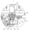
Accompanying drawing 4 is the A-A cutaway view of the utility model;
Accompanying drawing 5 is the partial view I of the A-A cutaway view of the utility model;
Accompanying drawing 6 is the partial view II of the A-A cutaway view of the utility model;
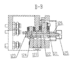
Accompanying drawing 7 is the B-B cutaway view of the utility model;
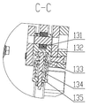
Accompanying drawing 8 is the C-C cutaway view of the utility model;
accompanying drawing 9 is the D-D cutaway view of the utility model.
Label is among the figure:
100, arc-shaped guide rail; 200, column; 300, crossbeam; 400, welding robot;
Wherein:
101, slide carriage; 102, nut; 110, camber line drive unit; 111, servomotor; 112, reductor; 113, driving gear; 114, driven gear; 115, sprocket wheel; 116, chain; 117, the 3rd spring; 118, the 3rd spring guide; 119, the 3rd guide rod; 120, vertical direction roller clamping device; 121, the first positive roller; 122, first roller shaft; 123, the second positive roller; 124, second roller shaft; 125, first guide rod; 126, first spring; 127, the first directed slide block; 130, horizontal direction roller clamping device; 131, first side wheel; 132, the second directed slide block; 133, second spring; 134, second guide rod; 135, second spring guide; 136, second side wheel; 137, the 3rd roller shaft; 210, rotating driving device; 211, rotating servo motor; 212, rotational delay machine; 213, rotation driving gear; 214, rotation driven gear; 215, rotating disk.
The specific embodiment
Set forth the preferred embodiment of the utility model below in conjunction with accompanying drawing in detail
; Thereby the protection domain of the utility model is made more explicit defining so that advantage of the present invention and characteristic can be easier to it will be appreciated by those skilled in the art that.
are shown in accompanying drawing 1 to accompanying drawing 9; The arc-shaped guide rail robot welding work station of present embodiment, it comprises arc-shaped guide rail 100, be connected in arc-shaped guide rail 100 and the column 200 that can move and can rotate around himself axis along arc-shaped guide rail 100 lines, drive camber line drive unit 110 that column 200 moves, drive rotating driving device 210 that column 200 rotates, be connected on the column 200 and relatively the crossbeam 300 that moves up and down of column 200, be connected in the welding robot 400 on the crossbeam.
arc-shaped guide rail 100 is provided with the slide carriage 101 that can move along arc-shaped guide rail 100, and column 200 is connected on the slide carriage 101 mutually rotationally, and the below of slide carriage 101 is provided with and can rolls and be close to the roller of arc-shaped guide rail 100 along arc-shaped guide rail 100.Slide carriage 101 belows are provided with one and are used to make said roller to be close to the roller clamping device of arc-shaped guide rail 100.The roller clamping device has played the effect that slide carriage 101 is stable at arc-shaped guide rail 100, makes slide carriage 101 more steady when arc-shaped guide rail 100 moves.This part will be in subsequent detailed description.
are shown in accompanying drawing 5; Camber line drive unit 110 comprises the servomotor 111, the reductor 112 that is connected with servomotor 111 that are installed on slide carriage 101, be connected with reductor 112 on by servomotor 111 drive the driving gear 113 that rotates, the driven gear 114 that is meshed with driving gear 113, coaxial with driven gear 114 and with the sprocket wheels 115 of driven gear 114 synchronous rotations, the chain 116 that is meshed with sprocket wheel 115, chain 116 is installed on the arc-shaped guide rail 100 and along the camber line setting of arc-shaped guide rail 100.
camber line drive unit 110 is equipped with the soft readjustment device simultaneously; It comprises the 3rd guide rod 119 perpendicular to the axis setting of driving gear 113, is enclosed within the spring 113 on the 3rd guide rod 119; The 3rd spring 113 offsets with reductor 112; The driving gear 113 that is connected with reductor 113 is offseted with driven gear 114, offset with chain 116 thereby make with driven gear 114 coaxial sprocket wheels 115.On the 3rd guide rod 119, also be socketed with the 3rd spring guide 118 and nut 102, be used for fixing the position of the 3rd spring 118.This soft readjustment device, through the elasticity of spring, real-time assurance sprocket wheel 115 teeth groove and good contact of chain 116 rollers.
as accompanying drawing 6 rotating driving devices 210 comprise the rotating servo motor 211 installed on the slide carriage 101, mutually be rotatably installed on side on the slide carriage 101 have the rotating disk 215 of the circle of side tooth, the rotational delay machine 212 that is connected with rotating servo motor 211, be connected with rotational delay machine 212 by rotating servo motor 211 drive rotations rotation driving gear 213, with rotate the rotation driven gear 214 that driving gear 213 is meshed; The side tooth of rotating disk 215 is meshed with rotation driven gear 214; Column 200 fixing with rotating disk 215 on, thereby drive columns 200 rotations through rotating servo motor 211.
foregoing roller comprise the first positive roller 121 that can roll along arc-shaped guide rail 100 upper surfaces, the second positive roller 123 that can roll along arc-shaped guide rail 100 lower surfaces, can along arc-shaped guide rail 100 first side wheel 131 that rolls of the medial surface of short inner side edge, can be along arc-shaped guide rail 100 second side wheel 136 of the lateral surface rolling of the outer side edges of length.
foregoing roller clamping device comprises the vertical direction roller clamping device 120 that makes the first positive roller 121 and the second positive roller 123 be close to arc-shaped guide rail 100, makes first side wheel 131 be close to the horizontal direction roller clamping device 130 of arc-shaped guide rail 100.
are shown in accompanying drawing 7; The second positive orientation slide block 128 that also can move along second positive roller 123 rotating directions on second roller shaft 124 that vertical direction roller clamping device 120 comprises the first positive orientation slide block 127 on first roller shaft 122 that is socketed in the first positive roller 121 and that can move along first positive roller 121 rotating directions, be socketed in the second positive roller 123; End perpendicular to the 121 axis settings of first roller shaft runs through first guide rod 125 that the first positive roller 121 is connected with the second positive roller 123; The other end of first guide rod 125 is provided with and pushes against the spring 126 that the first directed slide block 127 offsets the first directed slide block 127 and the second directed slide block 128; The central shaft of the central shaft of first roller shaft 121 and second roller shaft 123 parallels, and the first positive roller 121 is identical with the rotating direction of the second positive roller 123.
are shown in accompanying drawing 8; Second guide rod 134 that horizontal direction roller clamping device 130 comprises the 3rd positive orientation slide block 132 on the 3rd roller shaft 137 that is socketed in first side wheel 131 and that can move along first side wheel, 131 rotating directions, is connected with first side wheel 131 perpendicular to an end of the 3rd roller shaft 137 axis settings; Second guide rod 134 is provided with second spring 133 that axially pushes against the 3rd directed slide block 132 along second guide rod 134 to the medial surface direction of arc-shaped guide rail 100; Also be with second spring guide on second guide rod 134, in order to fixing second spring 133.
the foregoing description is only for explaining the technical conceive and the characteristics of the utility model; Its purpose is to let the personage who is familiar with this technology can understand content of the utility model and enforcement according to this, can not limit the protection domain of the utility model with this.All equivalences of being done according to the utility model spirit change or modify, and all should be encompassed within the protection domain of the utility model.
Claims (9)
1. arc-shaped guide rail robot welding work station is characterized in that: it comprises arc-shaped guide rail (100), be connected in said arc-shaped guide rail (100) and the column (200) that can move and can rotate around himself axis along arc-shaped guide rail (100), drive camber line drive unit (110) that said column (200) moves, drive rotating driving device (210) that said column (200) rotates, be connected on the said column (200) and relatively the crossbeam (300) that moves up and down of column (200), be connected in the welding robot (400) on the crossbeam.
2. arc-shaped guide rail robot welding work station according to claim 1; It is characterized in that: described arc-shaped guide rail (100) is provided with can be along the mobile slide carriage (101) of arc-shaped guide rail (100); Said column (200) is connected on the slide carriage (101) mutually rotationally, and the below of said slide carriage (101) is provided with and can rolls and be close to the roller of arc-shaped guide rail (100) along arc-shaped guide rail (100).
3. arc-shaped guide rail robot welding work station according to claim 2 is characterized in that: said slide carriage (101) below is provided with one and is used to make said roller to be close to the roller clamping device of arc-shaped guide rail (100).
4. according to claim 2 or 3 described arc-shaped guide rail robot welding work stations; It is characterized in that: described camber line drive unit (110) comprises servomotor (111), be installed on the said slide carriage (101) by said servomotor (111) drive the driving gear (113) that rotates, the driven gear (114) that is meshed with said driving gear (113), coaxial with said driven gear (114) and with the sprocket wheel (115) of driven gear (114) rotation synchronously, the chain (116) that is meshed with said sprocket wheel (115), said chain (116) is installed on described arc-shaped guide rail (100) upward and along the camber line setting of arc-shaped guide rail (100).
5. according to claim 2 or 3 described arc-shaped guide rail robot welding work stations; It is characterized in that: described rotating driving device (210) comprise rotating servo motor (211), mutually be rotatably installed on side on the said slide carriage (101) have the side tooth rotating disk (215), be installed on and drive the rotation driving gear (213) that rotates, the rotation driven gear (214) that is meshed with said rotation driving gear (213) by said rotating servo motor (211) on the said slide carriage (101); The side tooth of described rotating disk (215) is meshed with described rotation driven gear (214), and described column (200) is fixed on the said rotating disk (215).
6. according to claim 2 or 3 described arc-shaped guide rail robot welding work stations, it is characterized in that: described roller comprise the first positive roller (121) that can roll along said arc-shaped guide rail (100) upper surface, the second positive roller (123) that can roll along said arc-shaped guide rail (100) lower surface, can along said arc-shaped guide rail (100) first side wheel (131) that rolls of the medial surface of short inner side edge, can be along said arc-shaped guide rail (100) second side wheel (136) of the lateral surface rolling of the outer side edges of length.
7. arc-shaped guide rail robot welding work station according to claim 6 is characterized in that: said roller clamping device comprises the vertical direction roller clamping device (120) that makes the described first positive roller (121) and the second positive roller (123) be close to arc-shaped guide rail (100), makes described first side wheel (131) be close to the horizontal direction roller clamping device (130) of arc-shaped guide rail (100).
8. arc-shaped guide rail robot welding work station according to claim 7; It is characterized in that: the second positive orientation slide block (128) that also can move along second positive roller (123) rotating direction on second roller shaft (124) that described vertical direction roller clamping device (120) comprises the first positive orientation slide block (127) on first roller shaft (122) that is socketed in the said first positive roller (121) and that can move along first positive roller (121) rotating direction, be socketed in the said second positive roller (123); End perpendicular to said first roller shaft (121) axis setting runs through first guide rod (125) that the first positive roller (121) is connected with the second positive roller (123); The other end of said first guide rod (125) is provided with and pushes against the spring (126) that the said first directed slide block (127) offsets the first directed slide block (127) and the second directed slide block (128); The central shaft of the central shaft of said first roller shaft (121) and second roller shaft (123) parallels, and the said first positive roller (121) is identical with the rotating direction of the second positive roller (123).
9. arc-shaped guide rail robot welding work station according to claim 7; It is characterized in that: described horizontal direction roller clamping device (130) comprises second guide rod (134) that the 3rd positive orientation slide block (132) on the 3rd roller shaft (137) that is socketed in said first side wheel (131) and that can move along first side wheel (131) rotating direction, an end that is provided with perpendicular to said the 3rd roller shaft (137) axis are connected with first side wheel (131), and described second guide rod (134) is provided with said second guide rod in edge (134) axially pushes against second spring (133) from the said the 3rd directed slide block (132) to the medial surface direction of said arc-shaped guide rail (100).
Priority Applications (1)
| Application Number | Priority Date | Filing Date | Title |
|---|---|---|---|
| CN2011203206794U CN202240209U (en) | 2011-08-30 | 2011-08-30 | Arc guide rail robot welding workstation |
Applications Claiming Priority (1)
| Application Number | Priority Date | Filing Date | Title |
|---|---|---|---|
| CN2011203206794U CN202240209U (en) | 2011-08-30 | 2011-08-30 | Arc guide rail robot welding workstation |
Publications (1)
| Publication Number | Publication Date |
|---|---|
| CN202240209U true CN202240209U (en) | 2012-05-30 |
Family
ID=46101510
Family Applications (1)
| Application Number | Title | Priority Date | Filing Date |
|---|---|---|---|
| CN2011203206794U Expired - Lifetime CN202240209U (en) | 2011-08-30 | 2011-08-30 | Arc guide rail robot welding workstation |
Country Status (1)
| Country | Link |
|---|---|
| CN (1) | CN202240209U (en) |
Cited By (24)
| Publication number | Priority date | Publication date | Assignee | Title |
|---|---|---|---|---|
| CN102756198A (en) * | 2012-07-19 | 2012-10-31 | 湖州久立管件有限公司 | Automatic welding device for longitudinal joint of heavy-caliber elbow |
| CN104439803A (en) * | 2014-11-14 | 2015-03-25 | 柳州市安龙机械设备有限公司 | Bent plate welding machine |
| CN104785983A (en) * | 2015-04-20 | 2015-07-22 | 骏马石油装备制造有限公司 | Robot welding work station |
| CN104923999A (en) * | 2015-06-15 | 2015-09-23 | 华南理工大学 | Rotatable welding torch device and welding method thereof |
| CN105057945A (en) * | 2015-07-13 | 2015-11-18 | 中国长江航运集团江东船厂 | Steel plate welding tool |
| CN105562955A (en) * | 2016-02-14 | 2016-05-11 | 赵子宁 | Automatic welding device for corrugated web plates |
| CN107225350A (en) * | 2017-06-07 | 2017-10-03 | 成都环龙汽车设备有限公司 | A kind of guide rail of welding robot |
| CN107498044A (en) * | 2017-07-10 | 2017-12-22 | 中建钢构武汉有限公司 | Electric arc 3d printing system |
| CN107598425A (en) * | 2017-10-21 | 2018-01-19 | 孟庆仕 | A kind of closed Underwater Welding robot |
| CN107790932A (en) * | 2016-08-31 | 2018-03-13 | 上海岩灵自动化工程有限公司 | A kind of instrument panel framework robot welding system |
| CN108582030A (en) * | 2018-07-18 | 2018-09-28 | 东北林业大学 | A kind of small-sized arc-shaped guide rail with slidably pedestal |
| CN108746935A (en) * | 2018-03-26 | 2018-11-06 | 北京石油化工学院 | The bead-welding technology of ring type workpiece |
| CN108789359A (en) * | 2018-06-14 | 2018-11-13 | 芜湖易泽中小企业公共服务股份有限公司 | A kind of production line robot quick splice track and its assembling method |
| CN109175760A (en) * | 2018-10-30 | 2019-01-11 | 上海双彩吉智能科技有限公司 | Full-automatic arc plate welding equipment |
| CN109848595A (en) * | 2017-11-03 | 2019-06-07 | 金门建筑有限公司 | Welding system and method |
| CN110153521A (en) * | 2018-01-22 | 2019-08-23 | 盐城鼎力达焊接科技有限公司 | A kind of fixed device of circuit board spot welding |
| CN110744165A (en) * | 2019-11-22 | 2020-02-04 | 天水天嘉电子有限公司 | Double-station chip welding device |
| CN110883472A (en) * | 2019-12-18 | 2020-03-17 | 安徽双骏智能科技有限公司 | Numerical control four-axis welding manipulator |
| CN112873246A (en) * | 2021-04-28 | 2021-06-01 | 中国建筑第五工程局有限公司 | Straddle type single-rail track beam welding robot workstation |
| CN113023275A (en) * | 2020-12-10 | 2021-06-25 | 浙江同济科技职业学院 | Rotary guide rail device and novel 0-turn-radius rotary guide rail positioning device |
| CN114559195A (en) * | 2022-03-14 | 2022-05-31 | 中核检修有限公司 | Cutting device |
| CN116652367A (en) * | 2023-06-19 | 2023-08-29 | 北京长征火箭装备科技有限公司 | Large-diameter high-precision heavy-load hollow rotary platform device |
| CN117324767A (en) * | 2023-09-15 | 2024-01-02 | 重庆奥方汽车零部件有限公司 | Lamp bead spot welding equipment |
| CN117548814A (en) * | 2023-09-27 | 2024-02-13 | 深圳市锐豪科技有限公司 | Precision parts welding and installation equipment assembled by artificial intelligence equipment |
-
2011
- 2011-08-30 CN CN2011203206794U patent/CN202240209U/en not_active Expired - Lifetime
Cited By (31)
| Publication number | Priority date | Publication date | Assignee | Title |
|---|---|---|---|---|
| CN102756198B (en) * | 2012-07-19 | 2014-12-03 | 湖州久立管件有限公司 | Automatic welding device for longitudinal joint of heavy-caliber elbow |
| CN102756198A (en) * | 2012-07-19 | 2012-10-31 | 湖州久立管件有限公司 | Automatic welding device for longitudinal joint of heavy-caliber elbow |
| CN104439803A (en) * | 2014-11-14 | 2015-03-25 | 柳州市安龙机械设备有限公司 | Bent plate welding machine |
| CN104785983A (en) * | 2015-04-20 | 2015-07-22 | 骏马石油装备制造有限公司 | Robot welding work station |
| CN104923999A (en) * | 2015-06-15 | 2015-09-23 | 华南理工大学 | Rotatable welding torch device and welding method thereof |
| CN105057945B (en) * | 2015-07-13 | 2017-06-20 | 中国长江航运集团江东船厂 | Steel plate welding tooling |
| CN105057945A (en) * | 2015-07-13 | 2015-11-18 | 中国长江航运集团江东船厂 | Steel plate welding tool |
| CN105562955A (en) * | 2016-02-14 | 2016-05-11 | 赵子宁 | Automatic welding device for corrugated web plates |
| CN107790932A (en) * | 2016-08-31 | 2018-03-13 | 上海岩灵自动化工程有限公司 | A kind of instrument panel framework robot welding system |
| CN107225350A (en) * | 2017-06-07 | 2017-10-03 | 成都环龙汽车设备有限公司 | A kind of guide rail of welding robot |
| CN107498044A (en) * | 2017-07-10 | 2017-12-22 | 中建钢构武汉有限公司 | Electric arc 3d printing system |
| CN107498044B (en) * | 2017-07-10 | 2019-07-16 | 中建钢构武汉有限公司 | Electric arc 3D printing system |
| CN107598425A (en) * | 2017-10-21 | 2018-01-19 | 孟庆仕 | A kind of closed Underwater Welding robot |
| CN109848595A (en) * | 2017-11-03 | 2019-06-07 | 金门建筑有限公司 | Welding system and method |
| CN110153521B (en) * | 2018-01-22 | 2021-04-09 | 盐城鼎力达焊接科技有限公司 | Fixing device for spot welding of circuit board |
| CN110153521A (en) * | 2018-01-22 | 2019-08-23 | 盐城鼎力达焊接科技有限公司 | A kind of fixed device of circuit board spot welding |
| CN108746935A (en) * | 2018-03-26 | 2018-11-06 | 北京石油化工学院 | The bead-welding technology of ring type workpiece |
| CN108789359A (en) * | 2018-06-14 | 2018-11-13 | 芜湖易泽中小企业公共服务股份有限公司 | A kind of production line robot quick splice track and its assembling method |
| CN108582030A (en) * | 2018-07-18 | 2018-09-28 | 东北林业大学 | A kind of small-sized arc-shaped guide rail with slidably pedestal |
| CN109175760A (en) * | 2018-10-30 | 2019-01-11 | 上海双彩吉智能科技有限公司 | Full-automatic arc plate welding equipment |
| CN110744165A (en) * | 2019-11-22 | 2020-02-04 | 天水天嘉电子有限公司 | Double-station chip welding device |
| CN110883472A (en) * | 2019-12-18 | 2020-03-17 | 安徽双骏智能科技有限公司 | Numerical control four-axis welding manipulator |
| CN113023275A (en) * | 2020-12-10 | 2021-06-25 | 浙江同济科技职业学院 | Rotary guide rail device and novel 0-turn-radius rotary guide rail positioning device |
| CN112873246A (en) * | 2021-04-28 | 2021-06-01 | 中国建筑第五工程局有限公司 | Straddle type single-rail track beam welding robot workstation |
| CN112873246B (en) * | 2021-04-28 | 2021-08-06 | 中国建筑第五工程局有限公司 | A straddle type monorail rail beam welding robot workstation |
| CN114559195A (en) * | 2022-03-14 | 2022-05-31 | 中核检修有限公司 | Cutting device |
| CN114559195B (en) * | 2022-03-14 | 2023-06-13 | 中核检修有限公司 | Cutting device |
| CN116652367A (en) * | 2023-06-19 | 2023-08-29 | 北京长征火箭装备科技有限公司 | Large-diameter high-precision heavy-load hollow rotary platform device |
| CN117324767A (en) * | 2023-09-15 | 2024-01-02 | 重庆奥方汽车零部件有限公司 | Lamp bead spot welding equipment |
| CN117324767B (en) * | 2023-09-15 | 2024-04-30 | 重庆奥方汽车零部件有限公司 | Lamp bead spot welding equipment |
| CN117548814A (en) * | 2023-09-27 | 2024-02-13 | 深圳市锐豪科技有限公司 | Precision parts welding and installation equipment assembled by artificial intelligence equipment |
Similar Documents
| Publication | Publication Date | Title |
|---|---|---|
| CN203664964U (en) | Efficient automatic cutting device for metallic square and rectangular pipes | |
| CN206356814U (en) | A kind of gear ring is double to drive packaged type positioner | |
| CN202271255U (en) | Steel pipe welding seam grinding device | |
| CN108147076B (en) | Automatic turning device of shaped steel | |
| CN110280943A (en) | A kind of welding equipment of multi-angle industrial robot | |
| CN202461346U (en) | All-in-one machine device for transporting manipulator | |
| CN102133696B (en) | Tank body circular seam welding machine | |
| CN203765237U (en) | T-shaped beam and H-shaped beam assembling device | |
| CN103846327B (en) | A kind of bending machine | |
| CN104485607B (en) | A kind of high-voltage maintenance robot with the three arms motion of single motor control | |
| CN205325025U (en) | A pipe flange welding machine | |
| CN106346188A (en) | Pneumatic turning type robot welding positioner | |
| CN103341679A (en) | Large-diameter long-pipe-fitting pipe-end cutting device | |
| CN110961854A (en) | Steel beam welding positioner | |
| CN203471183U (en) | Welding device and automatic welding machine with welding device | |
| CN201807853U (en) | Mobile and rotary work table | |
| CN203945057U (en) | Rotation type positioner | |
| CN211305394U (en) | Steel beam welding positioner | |
| CN203356810U (en) | Pipe end cutting device of long large-diameter pipe fittings | |
| CN203918216U (en) | A kind of top electrode robot arm device of dull and stereotyped mash welder | |
| CN203754351U (en) | Jacking machine | |
| CN212634517U (en) | A free-angle cutting machine | |
| CN104096960A (en) | Upper electrode mechanical arm of plate point welding machine | |
| CN106964921A (en) | A kind of full-automatic wall-hanging solar inner bag grouping machine | |
| CN207710129U (en) | A kind of adjustable compound roller wheel machine of Intelligent welding system |
Legal Events
| Date | Code | Title | Description |
|---|---|---|---|
| C14 | Grant of patent or utility model | ||
| GR01 | Patent grant | ||
| CX01 | Expiry of patent term |
Granted publication date: 20120530 |
|
| CX01 | Expiry of patent term |