KR20170128675A - A method of forming a multi-element alloy thin film composite - Google Patents
A method of forming a multi-element alloy thin film composite Download PDFInfo
- Publication number
- KR20170128675A KR20170128675A KR1020160058285A KR20160058285A KR20170128675A KR 20170128675 A KR20170128675 A KR 20170128675A KR 1020160058285 A KR1020160058285 A KR 1020160058285A KR 20160058285 A KR20160058285 A KR 20160058285A KR 20170128675 A KR20170128675 A KR 20170128675A
- Authority
- KR
- South Korea
- Prior art keywords
- tool
- thin film
- coating
- coating equipment
- depositing
- Prior art date
Links
Images


Classifications
-
- C—CHEMISTRY; METALLURGY
- C23—COATING METALLIC MATERIAL; COATING MATERIAL WITH METALLIC MATERIAL; CHEMICAL SURFACE TREATMENT; DIFFUSION TREATMENT OF METALLIC MATERIAL; COATING BY VACUUM EVAPORATION, BY SPUTTERING, BY ION IMPLANTATION OR BY CHEMICAL VAPOUR DEPOSITION, IN GENERAL; INHIBITING CORROSION OF METALLIC MATERIAL OR INCRUSTATION IN GENERAL
- C23C—COATING METALLIC MATERIAL; COATING MATERIAL WITH METALLIC MATERIAL; SURFACE TREATMENT OF METALLIC MATERIAL BY DIFFUSION INTO THE SURFACE, BY CHEMICAL CONVERSION OR SUBSTITUTION; COATING BY VACUUM EVAPORATION, BY SPUTTERING, BY ION IMPLANTATION OR BY CHEMICAL VAPOUR DEPOSITION, IN GENERAL
- C23C14/00—Coating by vacuum evaporation, by sputtering or by ion implantation of the coating forming material
- C23C14/22—Coating by vacuum evaporation, by sputtering or by ion implantation of the coating forming material characterised by the process of coating
- C23C14/56—Apparatus specially adapted for continuous coating; Arrangements for maintaining the vacuum, e.g. vacuum locks
-
- C—CHEMISTRY; METALLURGY
- C23—COATING METALLIC MATERIAL; COATING MATERIAL WITH METALLIC MATERIAL; CHEMICAL SURFACE TREATMENT; DIFFUSION TREATMENT OF METALLIC MATERIAL; COATING BY VACUUM EVAPORATION, BY SPUTTERING, BY ION IMPLANTATION OR BY CHEMICAL VAPOUR DEPOSITION, IN GENERAL; INHIBITING CORROSION OF METALLIC MATERIAL OR INCRUSTATION IN GENERAL
- C23C—COATING METALLIC MATERIAL; COATING MATERIAL WITH METALLIC MATERIAL; SURFACE TREATMENT OF METALLIC MATERIAL BY DIFFUSION INTO THE SURFACE, BY CHEMICAL CONVERSION OR SUBSTITUTION; COATING BY VACUUM EVAPORATION, BY SPUTTERING, BY ION IMPLANTATION OR BY CHEMICAL VAPOUR DEPOSITION, IN GENERAL
- C23C14/00—Coating by vacuum evaporation, by sputtering or by ion implantation of the coating forming material
- C23C14/02—Pretreatment of the material to be coated
- C23C14/021—Cleaning or etching treatments
- C23C14/022—Cleaning or etching treatments by means of bombardment with energetic particles or radiation
-
- C—CHEMISTRY; METALLURGY
- C23—COATING METALLIC MATERIAL; COATING MATERIAL WITH METALLIC MATERIAL; CHEMICAL SURFACE TREATMENT; DIFFUSION TREATMENT OF METALLIC MATERIAL; COATING BY VACUUM EVAPORATION, BY SPUTTERING, BY ION IMPLANTATION OR BY CHEMICAL VAPOUR DEPOSITION, IN GENERAL; INHIBITING CORROSION OF METALLIC MATERIAL OR INCRUSTATION IN GENERAL
- C23C—COATING METALLIC MATERIAL; COATING MATERIAL WITH METALLIC MATERIAL; SURFACE TREATMENT OF METALLIC MATERIAL BY DIFFUSION INTO THE SURFACE, BY CHEMICAL CONVERSION OR SUBSTITUTION; COATING BY VACUUM EVAPORATION, BY SPUTTERING, BY ION IMPLANTATION OR BY CHEMICAL VAPOUR DEPOSITION, IN GENERAL
- C23C14/00—Coating by vacuum evaporation, by sputtering or by ion implantation of the coating forming material
- C23C14/06—Coating by vacuum evaporation, by sputtering or by ion implantation of the coating forming material characterised by the coating material
- C23C14/0641—Nitrides
-
- C—CHEMISTRY; METALLURGY
- C23—COATING METALLIC MATERIAL; COATING MATERIAL WITH METALLIC MATERIAL; CHEMICAL SURFACE TREATMENT; DIFFUSION TREATMENT OF METALLIC MATERIAL; COATING BY VACUUM EVAPORATION, BY SPUTTERING, BY ION IMPLANTATION OR BY CHEMICAL VAPOUR DEPOSITION, IN GENERAL; INHIBITING CORROSION OF METALLIC MATERIAL OR INCRUSTATION IN GENERAL
- C23C—COATING METALLIC MATERIAL; COATING MATERIAL WITH METALLIC MATERIAL; SURFACE TREATMENT OF METALLIC MATERIAL BY DIFFUSION INTO THE SURFACE, BY CHEMICAL CONVERSION OR SUBSTITUTION; COATING BY VACUUM EVAPORATION, BY SPUTTERING, BY ION IMPLANTATION OR BY CHEMICAL VAPOUR DEPOSITION, IN GENERAL
- C23C14/00—Coating by vacuum evaporation, by sputtering or by ion implantation of the coating forming material
- C23C14/22—Coating by vacuum evaporation, by sputtering or by ion implantation of the coating forming material characterised by the process of coating
- C23C14/24—Vacuum evaporation
- C23C14/32—Vacuum evaporation by explosion; by evaporation and subsequent ionisation of the vapours, e.g. ion-plating
- C23C14/325—Electric arc evaporation
-
- C—CHEMISTRY; METALLURGY
- C23—COATING METALLIC MATERIAL; COATING MATERIAL WITH METALLIC MATERIAL; CHEMICAL SURFACE TREATMENT; DIFFUSION TREATMENT OF METALLIC MATERIAL; COATING BY VACUUM EVAPORATION, BY SPUTTERING, BY ION IMPLANTATION OR BY CHEMICAL VAPOUR DEPOSITION, IN GENERAL; INHIBITING CORROSION OF METALLIC MATERIAL OR INCRUSTATION IN GENERAL
- C23C—COATING METALLIC MATERIAL; COATING MATERIAL WITH METALLIC MATERIAL; SURFACE TREATMENT OF METALLIC MATERIAL BY DIFFUSION INTO THE SURFACE, BY CHEMICAL CONVERSION OR SUBSTITUTION; COATING BY VACUUM EVAPORATION, BY SPUTTERING, BY ION IMPLANTATION OR BY CHEMICAL VAPOUR DEPOSITION, IN GENERAL
- C23C14/00—Coating by vacuum evaporation, by sputtering or by ion implantation of the coating forming material
- C23C14/22—Coating by vacuum evaporation, by sputtering or by ion implantation of the coating forming material characterised by the process of coating
- C23C14/34—Sputtering
-
- C—CHEMISTRY; METALLURGY
- C23—COATING METALLIC MATERIAL; COATING MATERIAL WITH METALLIC MATERIAL; CHEMICAL SURFACE TREATMENT; DIFFUSION TREATMENT OF METALLIC MATERIAL; COATING BY VACUUM EVAPORATION, BY SPUTTERING, BY ION IMPLANTATION OR BY CHEMICAL VAPOUR DEPOSITION, IN GENERAL; INHIBITING CORROSION OF METALLIC MATERIAL OR INCRUSTATION IN GENERAL
- C23C—COATING METALLIC MATERIAL; COATING MATERIAL WITH METALLIC MATERIAL; SURFACE TREATMENT OF METALLIC MATERIAL BY DIFFUSION INTO THE SURFACE, BY CHEMICAL CONVERSION OR SUBSTITUTION; COATING BY VACUUM EVAPORATION, BY SPUTTERING, BY ION IMPLANTATION OR BY CHEMICAL VAPOUR DEPOSITION, IN GENERAL
- C23C14/00—Coating by vacuum evaporation, by sputtering or by ion implantation of the coating forming material
- C23C14/22—Coating by vacuum evaporation, by sputtering or by ion implantation of the coating forming material characterised by the process of coating
- C23C14/54—Controlling or regulating the coating process
- C23C14/542—Controlling the film thickness or evaporation rate
-
- C—CHEMISTRY; METALLURGY
- C23—COATING METALLIC MATERIAL; COATING MATERIAL WITH METALLIC MATERIAL; CHEMICAL SURFACE TREATMENT; DIFFUSION TREATMENT OF METALLIC MATERIAL; COATING BY VACUUM EVAPORATION, BY SPUTTERING, BY ION IMPLANTATION OR BY CHEMICAL VAPOUR DEPOSITION, IN GENERAL; INHIBITING CORROSION OF METALLIC MATERIAL OR INCRUSTATION IN GENERAL
- C23C—COATING METALLIC MATERIAL; COATING MATERIAL WITH METALLIC MATERIAL; SURFACE TREATMENT OF METALLIC MATERIAL BY DIFFUSION INTO THE SURFACE, BY CHEMICAL CONVERSION OR SUBSTITUTION; COATING BY VACUUM EVAPORATION, BY SPUTTERING, BY ION IMPLANTATION OR BY CHEMICAL VAPOUR DEPOSITION, IN GENERAL
- C23C14/00—Coating by vacuum evaporation, by sputtering or by ion implantation of the coating forming material
- C23C14/58—After-treatment
Landscapes
- Chemical & Material Sciences (AREA)
- Chemical Kinetics & Catalysis (AREA)
- Engineering & Computer Science (AREA)
- Materials Engineering (AREA)
- Mechanical Engineering (AREA)
- Metallurgy (AREA)
- Organic Chemistry (AREA)
- Physical Vapour Deposition (AREA)
- Cutting Tools, Boring Holders, And Turrets (AREA)
Abstract
Description
본 발명은 다원계 합금 복합 박막 형성공법에 관한 것으로, 보다 구체적으로는, 고함량의 실리콘 성분 포함에도 박막의 경도와 내열성과 내마모성 및 윤활성을 우수하게 할 수 있어 열응력 저항력 증대와 더불어 피로균일 진전속도를 지연시킬 수 있고, 코팅작업을 용이하게 이루어 생산성의 향상은 물론, 공구의 수명향상을 이룰 수 있으며, 잔류응력 제거를 통해 공구에 증착된 박막의 형상을 일정하게 하여 공구의 변형을 방지토록 함으로써 구조가 복잡한 제품을 원하는 형상으로 가공할 수 있는 다원계 합금 복합 박막 형성공법에 관한 것이다.More specifically, the present invention relates to a method for forming a multi-layered alloy composite thin film, and more particularly, to a method for forming a multi-layered alloy composite thin film, The speed can be delayed, the coating operation can be facilitated, and the productivity of the tool can be improved as well as the life of the tool can be improved. In addition, the shape of the thin film deposited on the tool is fixed by removing the residual stress, To thereby produce a multi-component alloy composite thin film forming method capable of processing a complicated structure into a desired shape.
일반적으로 진공증착 도금은 물리적 증착도금과 화학적 증착도금으로 분류되고, 물리적 증착도금은 다시 증착(Evaporation)도금, 이온도금(lon plating) 및 스터퍼링 도금으로 분류할 수 있다.In general, vacuum deposition plating is classified into physical vapor deposition plating and chemical vapor deposition plating, and physical vapor deposition plating can be classified again into evaporation plating, ion plating and lapping plating.
그리고, 이온도금은 다시 아크이온도금, HCD 이온도금, 다음극 이온도금 등으로 세분되는데, 이들은 각기 다른 용도에 사용되고 그 장·단점들 역시 서로 다르다.The ion plating is further divided into arc ion plating, HCD ion plating, and next pole ion plating, which are used for different purposes, and their advantages and disadvantages are also different.
또한, 종래의 진공증착을 도금장치들은 하나의 챔버내에서는 한가지 도금만을 할 수 있었다.In addition, the conventional vacuum vapor deposition plating apparatuses could only perform one plating in one chamber.
즉, 아크이온 도금장치와 HCD 이온 도금장치는 서로 별개의 장치로 구성되어 있기 때문에 이미 행하던 것과 다른 도금을 하기 위해서는 그에 필요한 장치들을 새로 구입해야만 하였으며, 이로 인해, 설치비용이 과다하고, 각 도금원리 면에서 본래 지니고 있는 문제점들로 인하여 피복 효과를 개선하기가 어려운 문제점들이 있었다.That is, since the arc ion plating apparatus and the HCD ion plating apparatus are composed of separate apparatuses, it is necessary to newly purchase the apparatuses necessary for plating different from the one that has already been done. As a result, the installation cost is excessive, There are problems that it is difficult to improve the coating effect owing to the inherent problems in the surface.
한편, 오늘날, 대부분의 절삭 공구는 Ti(C,N), TiN, (Ti,Al)N, (Ti,Si)N, (Al, Cr)N 또는 Al2O3와 같은 PVD 또는 CVD 코팅으로 코팅된다.On the other hand, today, most cutting tools are coated with PVD or CVD coatings such as Ti (C, N), TiN, (Ti, Al) N, (Ti, Si) N, (Al, Cr) N or Al2O3.
그리고, PVD 코팅은 일반적으로 CVD 코팅보다 얇게 되어 있는데, 상기 PVD 코팅을 CVD 코팅과 비교하여 예를 들면, 압축 응력, 미세 입자 코팅, 하중 변화를 견디는 데 더 양호한 능력을 가지고 있어 몇 가지 유익한 특성을 갖는다.And, PVD coatings are generally thinner than CVD coatings, which have a better ability to withstand compressive stresses, microparticle coatings, and load changes compared to CVD coatings, for example, .
그러나, 대부분의 아크 증착 PVD 코팅은 코팅 내부에 묻혀있는 또는 코팅의 표면상에 존재하는 작은 구형의 마이크로 파티클 또는 액적이라고도 불리는 금속 거대입자로 인한 문제점이 있다.However, most arc-deposited PVD coatings are problematic due to small spherical microparticles buried in the coating or on the surface of the coating, or metal macroparticles, also referred to as droplets.
다시 말해서, 코팅을 증착할 때에, 상기 거대 입자들은 대전된 금속 이온의 유입 플럭스를 차단할 수 있어 거대입자의 인접한 주변에서 코팅에 공극이 형성되고, 이로 인해, 코팅과 거대 입자 사이의 부착이 감소하여, 거대입자는 증착 공정 또는 가공 직후 또는 가공 중에 떨어져 나갈 수 있게 되는 것이다.In other words, when depositing the coating, the macromolecules can block the incoming flux of charged metal ions, creating voids in the coating in the immediate vicinity of the macromolecules, thereby reducing adhesion between the coating and macromolecules , The macromolecule can fall off either during the deposition process or immediately after processing or during processing.
이에 따라, 공극, 세공 또는 극단적인 경우에는 기재까지 하방으로의 구멍을 가지는 열등한 품질의 코팅이 될 수도 있었으며, 이와 같은 열등한 품질의 코팅을 지닌 절삭공구를 사용하면 공구의 절살날에 균열이 생기게 되어 날의 칩핑 또는 파손이 쉽게 발생하는 문제점이 있었다.This could result in a coating of inferior quality with pores, pores or, in extreme cases, holes down to the substrate, and the use of a cutting tool with such inferior quality coatings would result in cracking of the tool, There is a problem that chipping or breakage of the blade easily occurs.
이에 본 출원인은 등록특허공보 제10-1556372호와 같은 "절삭공구의 PVD 코팅장비 및 이를 이용한 코팅공법"을 개발하여 등록 받았다.Accordingly, the present applicant has developed and registered "PVD coating equipment for cutting tools and a coating method using the same" as in the registered patent publication No. 10-1556372.
그러나, 전술한 종래의 "절삭공구의 PVD 코팅장비 및 이를 이용한 코팅공법"은 아크코팅부와 스퍼터링코팅부를 이용한 이중코팅으로 절삭공구를 코팅하도록 되어 있으나, 코팅을 하는 방법에 있어 효율이 떨어지는 문제점이 있었다.However, in the above-mentioned conventional "PVD coating equipment of cutting tool and coating method using the same," the cutting tool is coated with a double coating using an arc coating part and a sputter coating part, there was.
또한, 상기 방법으로 제작된 절삭공구는 내마모성과 내부착성이 안정적으로 이루지지 않기 때문에 절삭공구를 이용한 절삭 가공시 조기 박리 및 칩핑으로 인한 마모가 쉽게 발생하는 문제점이 있었으며, 이로 인해, 코팅에 따른 비용이 증대되는 원인이 되었다.In addition, since the cutting tool manufactured by the above method is not stable in abrasion resistance and adhesion resistance, there is a problem that abrasion due to early peeling and chipping occurs easily during cutting using a cutting tool, The cost was increased.
따라서, 본 출원인은 코팅을 효율적으로 이루어 코팅에 따른 시간과 비용을 절약할 수 있을 뿐만 아니라, 고온의 절삭 칩(Chip)으로부터의 열응력(thermal stress, 熱應力) 저항력 증대를 이룰 수 있고, 고속 가공시 마찰열에 대한 피로균일 진전속도를 지연시킬 수 있도록 고경도, 고내열, 고윤활성을 가지는 다원계 합금 복합 막막 형성공법을 개발하기에 이르렀다.Accordingly, the Applicant has found that the coating can be efficiently performed to save time and cost due to the coating, and the thermal stress (thermal stress) resistance can be increased from a high temperature cutting chip, A method of forming a multi-layered alloy composite membrane having high hardness, high heat resistance, and high lubricity so as to delay the fatigue uniform propagation speed of frictional heat during machining has been developed.
본 발명의 목적은 AlCrN을 이용한 아크방전 방식으로 표면층 이물질이 제거된 공구의 표면에 1차 박막 증착을 용이하게 이룬 다음, AlCrSiN을 이용한 아크방전 방식으로 1차 박막 증착된 공구에 2차 방막 증착을 이루고, CrZrN을 이용한 비정상 글로우방전인 스퍼터링을 이용하여 2차 박막 증착된 공구에 3차 박막 증착을 이룸으로써, 고함량의 실리콘 성분 포함에도 박막의 경도와 내열성과 내마모성 및 윤활성을 우수하게 할 수 있으며, 이를 통해, 열응력 저항력 증대와 더불어, 피로균일 진전속도를 지연시킬 수 있는 다원계 합금 복합 박막 형성공법을 제공하는데 있다.An object of the present invention is to provide a method of depositing a first thin film on a surface of a tool having a surface layer foreign material removed by an arc discharge method using AlCrN and then forming a second thin film on a first thin film deposited by an arc discharge method using AlCrSiN By forming a tertiary thin film on a secondary thin film deposited by sputtering, which is an abnormal glow discharge using CrZrN, the hardness, heat resistance, abrasion resistance and lubricity of the thin film can be improved even with a high content of silicon component , Thereby providing a multi-layered alloy composite thin film forming method capable of delaying the rate of fatigue uniform propagation along with an increase in thermal stress resistance.
또한, 본 발명은 공구 하층코팅단계와 공구 중층코팅단계와 공기 상층코팅단계에서 각각 형성되는 1, 2, 3차 박막 증착의 두께가 3 : 1 : 1의 비율로 형성되는 것에 의해, 밀착력이 우수하고 내마모성이 좋은 1차 박막을 공구의 표면에 두꺼운 두께로 용이하게 증착시킬 수 있을 뿐만 아니라, 2차 박막에 함량되어 있는 실리콘 성분에 의해 가공시 순간적으로 올라가는 고열에도 열 충격 및 열크랙에 의한 미세한 균열의 진전을 늦출 수 있으며, 마찰계수가 낮아 내마모성이 1차 박막보다 우수한 3차 박막을 2차 박막의 표면에 얇은 두께로 증착하는 것으로 내구성과 윤활성 및 표면조도를 높임으로써 공구 수명의 향상을 이룰 수 있는 다원계 합금 복합 박막 형성공법을 제공하는데 목적이 있다.In addition, the present invention is characterized in that the thicknesses of the first, second and third thin film depositions formed in the tool lower layer coating step, the tool intermediate layer coating step and the air upper layer coating step are respectively 3: 1: 1, And the abrasion-resistant primary thin film can be easily deposited on the surface of the tool to a thick thickness. In addition, the silicon component contained in the secondary thin film enables the high temperature, which is instantaneously raised during processing, By thinning the third thin film, which has a lower coefficient of friction and lower friction coefficient than the first thin film, on the surface of the second thin film, it improves durability, lubrication and surface roughness and improves tool life. The present invention also provides a method of forming a multi-layered alloy composite thin film.
아울러, 본 발명은 공구 하층코팅단계와 공구 중층코팅단계와 공기 상층코팅단계 다음에, 각각의 박막 증착시 형성되는 잔류응력을 제거하는 단계를 각각 추가 구성하는 것을 통해 제작되는 공구의 변형을 방지토록 함으로써 구조가 복잡한 제품을 원하는 형상으로 용이하게 가공할 수 있는 다원계 합금 복합 박막 형성공법을 제공하는데 목적이 있다.In addition, the present invention prevents the deformation of the tool, which is manufactured through additionally constituting the step of removing the residual stress formed in the respective thin film deposition, following the tool lower layer coating step, the tool intermediate layer coating step and the air upper layer coating step The present invention has been made in view of the above problems, and it is an object of the present invention to provide a multi-element alloy composite thin film forming method capable of easily processing a complicated structure into a desired shape.
상기와 같은 목적을 달성하기 위한 본 발명은 아크코팅부와 스퍼터링코팅부와 HCD에칭부와 진공펌프가 구성된 코팅장비를 이용하여 공구의 표면에 박막을 증착시키는 공법에 있어서, 테이블카트를 이용하여 공구를 코팅장비의 내부에 배치시키는 공구 장입단계; 도어를 폐쇄하여 코팅장비를 밀폐시킨 후, 진공펌프를 작동시켜 상기 코팅장비 내부를 진공상태로 만드는 코팅장비 진공형성단계; 상기 코팅장비의 내부로 열을 가하여 코팅장비 내부의 가스를 제거하는 코팅장비 가스제거단계; 플라즈마 에칭을 통해 코팅장비 내부에 투입된 공구의 표면층 이물질을 제거하는 공구 에칭단계; AlCrN을 이용한 아크방전 방식으로 공구의 표면에 1차 박막을 증착시키는 공구 하층코팅단계; AlCrSiN을 이용한 아크방전 방식으로 1차 박막 증착된 공구에 2차 박막을 증착시키는 공구 중층코팅단계; CrZrN을 이용한 비정상 글로우방전 방식으로 2차 박막 증착된 공구에 3차 박막을 증착시키는 공구 상층코팅단계; 코팅장비의 내부를 진공 냉각하여 다층 코팅된 공구를 냉각시키는 진공 냉각단계;를 포함하여 이루어진 것을 특징으로 하는 다원계 합금 복합 박막 형성공법을 제공한다.According to an aspect of the present invention, there is provided a method of depositing a thin film on a surface of a tool by using a coating equipment comprising an arc coating portion, a sputter coating portion, an HCD etching portion, and a vacuum pump, Into the interior of the coating equipment; A coating equipment vacuum forming step of closing the door to seal the coating equipment and then operating the vacuum pump to vacuum the interior of the coating equipment; A coating equipment gas removing step of applying heat to the interior of the coating equipment to remove gas inside the coating equipment; A tool etching step of removing surface layer impurities of the tool which has been introduced into the coating equipment through plasma etching; A tool lower layer coating step of depositing a primary thin film on the surface of the tool by an arc discharge method using AlCrN; A tool intermediate layer coating step of depositing a secondary thin film on a primary thin film deposited tool by an arc discharge method using AlCrSiN; A tool upper layer coating step of depositing a third thin film on a second thin film deposited tool with an abnormal glow discharge method using CrZrN; And a vacuum cooling step of cooling the interior of the coating equipment by vacuum cooling to cool the multi-layer coated tool.
본 발명의 다원계 합금 복합 박막 형성공법을 이용하면, AlCrN을 이용한 아크방전(Arc Discharge) 방식으로 표면층 이물질이 제거된 공구의 표면에 1차 박막 증착을 용이하게 이룬 다음, AlCrSiN을 이용한 아크방전(Arc Discharge) 방식으로 1차 박막 증착된 공구에 2차 방막 증착을 이루고, CrZrN을 이용한 비정상 글로우방전(Abnormal Glow Discharge)인 스퍼터링(Sputtering)을 이용하여 2차 박막 증착된 공구에 3차 박막 증착을 이룸으로써, 고함량의 실리콘 성분 포함에도 박막의 경도와 내열성과 내마모성 및 윤활성을 우수하게 할 수 있으며, 이를 통해, 열응력(thermal stress, 熱應力) 저항력 증대와 더불어, 피로균일 진전속도를 지연시킬 수 있는 장점이 있다.Using the multi-component alloy composite thin film forming method of the present invention, primary thin film deposition can be easily performed on the surface of a tool having surface layer foreign substances removed by an arc discharge method using AlCrN, and arc discharge using AlCrSiN Arc Discharge method, and a tertiary thin film deposition is performed on a tool deposited by a secondary thin film deposition using sputtering, which is an abnormal glow discharge using CrZrN. It is possible to improve the hardness, heat resistance, abrasion resistance and lubricity of the thin film even with a high content of silicon component, thereby increasing the thermal stress (thermal stress) resistance and delaying the fatigue uniform propagation speed There are advantages to be able to.
또한, 본 발명은 공구 하층코팅단계와 공구 중층코팅단계와 공기 상층코팅단계에서 각각 형성되는 1, 2, 3차 박막 증착의 두께가 3 : 1 : 1의 비율로 형성되는 것에 의해, 밀착력이 우수하고 내마모성이 좋은 1차 박막을 공구의 표면에 두꺼운 두께로 용이하게 증착시킬 수 있을 뿐만 아니라, 2차 박막에 함량되어 있는 실리콘 성분에 의해 가공시 순간적으로 올라가는 고열에도 열 충격 및 열크랙에 의한 미세한 균열의 진전을 늦출 수 있으며, 마찰계수가 낮아 내마모성이 1차 박막보다 우수한 3차 박막을 2차 박막의 표면에 얇은 두께로 증착하는 것으로 내구성과 윤활성 및 표면조도를 높임으로써 공구 수명의 향상을 이룰 수 있는 장점이 있다.In addition, the present invention is characterized in that the thicknesses of the first, second and third thin film depositions formed in the tool lower layer coating step, the tool intermediate layer coating step and the air upper layer coating step are respectively 3: 1: 1, And the abrasion-resistant primary thin film can be easily deposited on the surface of the tool to a thick thickness. In addition, the silicon component contained in the secondary thin film enables the high temperature, which is instantaneously raised during processing, By thinning the third thin film, which has a lower coefficient of friction and lower friction coefficient than the first thin film, on the surface of the second thin film, it improves durability, lubrication and surface roughness and improves tool life. There are advantages to be able to.
아울러, 본 발명은 공구 하층코팅단계와 공구 중층코팅단계와 공기 상층코팅단계 다음에, 각각의 박막 증착시 형성되는 잔류응력(residual stress , 殘留應力)을 제거하는 단계를 각각 추가 구성하는 것을 통해 제작되는 공구의 변형을 방지토록 할 수 있어 구조가 복잡한 제품을 원하는 형상으로 용이하게 가공할 수 있는 유용한 발명이다.In addition, the present invention provides a method for manufacturing a semiconductor device, which comprises the steps of separately removing the residual stress (residual stress) formed in each thin film deposition step after the tool lower layer coating step, the tool intermediate layer coating step and the air upper layer coating step It is possible to prevent the deformation of the tool, and it is a useful invention that can easily process a complicated structure into a desired shape.
도 1은 본 발명의 다원계 합금 복합 박막 형성공법을 도시한 순서도.
도 2는 본 발명의 코팅장비와 테이블카트를 도시한 사시도.
도 3은 본 발명의 코팅장비를 도시한 모식도.
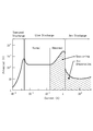
도 4는 글로우방전과 아크방전의 전압-전류 특성을 도시한 그래프.BRIEF DESCRIPTION OF THE DRAWINGS FIG. 1 is a flowchart showing a multi-element alloy composite thin film forming method of the present invention. FIG.
2 is a perspective view showing the coating equipment and table cart of the present invention.
3 is a schematic diagram showing the coating equipment of the present invention.
4 is a graph showing voltage-current characteristics of glow discharge and arc discharge.
상기와 같은 문제점을 해결하기 위한 본 발명의 구성을 살펴보면 다음과 같다.Hereinafter, the structure of the present invention will be described.
본 발명은 도 1 내지 도 4에 도시된 바와 같이 아크코팅부(10)와 스퍼터링코팅부(20)와 HCD에칭부(30)와 진공펌프(40)가 구성된 코팅장비(50)를 이용하여 공구의 표면에 박막을 증착시키는 다원계 합금 복합 박막 형성공법에 관한 것으로, 테이블카트(60)를 이용하여 공구(9)를 코팅장비(50)의 내부에 배치시키는 공구 장입단계(S10); 도어(51)를 폐쇄하여 코팅장비(50)를 밀폐시킨 후, 진공펌프(40)를 작동시켜 상기 코팅장비(50) 내부를 진공상태로 만드는 코팅장비 진공형성단계(S20); 상기 코팅장비(50)의 내부로 열을 가하여 코팅장비(50) 내부의 가스를 제거하는 코팅장비 가스제거단계(S30); 플라즈마 에칭을 통해 코팅장비(50) 내부에 투입된 공구(9)의 표면층 이물질을 제거하는 공구 에칭단계(S40); AlCrN을 이용한 아크방전(Arc Discharge) 방식으로 공구의 표면에 1차 박막(1)을 증착시키는 공구 하층코팅단계(S50); AlCrSiN을 이용한 아크방전(Arc Discharge) 방식으로 1차 박막(1) 증착된 공구에 2차 박막(2)을 증착시키는 공구 중층코팅단계(S60); CrZrN을 이용한 비정상 글로우방전(Abnormal Glow Discharge ; Sputtering) 방식으로 2차 박막(2) 증착된 공구에 3차 박막(3)을 증착시키는 공구 상층코팅단계(S70); 코팅장비(50)의 내부를 진공 냉각하여 다층 코팅된 공구(9)를 냉각시키는 진공 냉각단계(S80);를 포함하여 이루어진 것을 특징으로 한다.1 to 4, the present invention can be applied to a
또한, 상기 코팅장비(50)는 아크코팅부(10)와 스퍼터링코팅부(20)와 HCD에칭부(30)와 진공펌프(40)가 설치된 챔버몸체(50a)를 구비하여 상기 챔버몸체(50a) 내부에 공구를 수용하는 구성으로, 전방에는 공구(9)를 챔버몸체(50a)에 수용하기 위해 개폐도어(51)가 구성되고, 상기 챔버몸체(51)의 내부에는 온도를 조절하기 위한 통상의 히터(55)가 구성된다.The
여기서, 상기 아크코팅부(10)는 종래에 공지된 바와 같이 챔버몸체(50a)에 설치된 상태로 자전 및 공전되는 공구(9)의 표면 코팅을 이루는 구성으로, 챔버몸체(50a)에 결합설치되는 아크모듈판(11)과, 상기 아크모듈판(11)에 결합설치되어 공구(9)를 향하여 광원을 조사하는 아크소스(13)를 구성하며, 제1, 2차 박막 증착을 위하여 AlCr 분말타켓과 1개와 AlCrSi 분말합금타켓 1개를 장착한다.Here, the
아울러, 상기 스퍼터링코팅부(20)는 종래에 공지된 바와 같이 챔버몸체(50a)에 설치된 상태로 자전 및 공전되는 공구(9)의 표면 즉, 2차 박막 증착된 공구에 3차 박막 증착을 이루는 구성으로, 챔버몸체의 결합설치되는 스퍼터모듈판(21)과, 상기 스퍼터모듈판(21)에 결합되어 공구(1)를 향하여 광원을 조사하는 스퍼터소스(23)를 구성하며, 제2 박막 증착을 위하여 CrZr 타겟을 장착한다.In addition, the sputtering
그리고, 상기 HCD에칭부(30)는 종래에 공지된 바와 같이 공구(9)에 코팅이 보다 잘 형성될 수 있도록 상기 공구(9)의 표면층에 묻어 있는 이물질을 제거하는 구성으로, 챔버몸체(50a) 내부에 형성된 증기압을 통해 용해된 확산판(미도시)의 입자가 진공중에 분사되도록 하는 작용을 함으로써 공구(9)의 표면을 에칭하는데 사용된다.The
더불어, 상기 진공펌프(40)는 종래에 공지된 바와 같이 상기 챔버몸체(50a)의 상부에 설치되어 아크코팅과 스퍼터링코팅 및 HCD에칭시 챔버몸체(50a) 내부의 압력을 조절하는 구성이다.In addition, the
더하여, 상기 테이블카트(60)는 종래에 공지된 바와 같이 공구(9)의 용이한 이동에 따른 장입 및 보관을 위한 구성이다.In addition, the
이하에서는 본 발명의 다원계 합금 복합 박막 형성공법에 대해 보다 상세히 설명한다.Hereinafter, the multi-element alloy composite thin film forming method of the present invention will be described in more detail.
첫째, 공구 장입단계(S10)는 테이블카트(60)를 이용하여 공구(9)를 코팅장비(50)에 구성된 챔버몸체(50a)의 내부에 배치시키는 단계로서, 이때, 상기 공구(9)는 종래에 공지된 테이블조립체(미도시)에 안착된 상태로 이동되어 챔버몸체(50a) 내부에 배치되며, 이로 인해, 상기 공구(9)는 테이블조립체의 구동에 따라 자전 및 공전을 할 수 있게 된다.First, the tool loading step S10 is a step of placing the tool 9 inside the
둘째, 코팅장비 진공형성단계(S20)는 상기와 같이 공구(9)를 코팅장비(50)의 챔버몸체(50a) 내부에 배치시킨 상태에서, 도어(51)를 폐쇄하여 챔버몸체(50a)의 내부를 밀폐시킨 후, 진공펌프(40)의 작동을 통해 상기 챔버몸에(50a)의 내부를 진공상태로 만드는 단계로서, 상기 진공펌프(40)를 이용한 배기로써 상기 코팅장비(50)의 챔버몸체(50a) 내부를 진공으로 만든다.Second, in the coating equipment vacuum forming step S20, while the tool 9 is disposed inside the
셋째, 코팅장비 가스제거단계(S30)는 상기 코팅장비(50)의 내부에 구성된 히터(66)를 가동시키는 것으로, 열을 가함으로써 코팅장비(50) 내부에 잔존하는 가스의 제거를 이루는 단계로써, 히터(55)에 의한 열 발생 및 진공펌프(40)를 이용한 배기를 통해 가스의 배출이 원활하게 이루어져, 코팅장비(50) 내부의 가스가 제거된다.Third, the coating equipment degassing step S30 is a step of activating the heater 66 built in the
넷째, 공구 에칭단계(S40)는 공지된 바와 같이 HCD소스의 광원으로 하여금 확산판을 용해시킴과 더불어, 코팅장비(50)의 내부에서 형성된 증기압을 통해 용해된 확산판의 입자가 진공중에 분사되는 작용에 의해 공구(9)의 표면층 이물질을 제거하는 단계로서, 플라즈마 에칭을 통해 이룬다.Fourth, the tool etching step (S40), as well known, allows the light source of the HCD source to dissolve the diffuser plate, and the particles of the diffuser plate dissolved through the vapor pressure formed inside the
그리고, 상기와 같은 공구(9)의 에칭이 이루어지기 전에는, 공구(9)의 에칭이 보다 원활하게 될 수 있도록, 상기 코팅장비(50) 내부에 배치된 공구(9)가 테이블조립체의 구동에 따라 자전 및 공전하는 작용이 먼저 이루어져야 하며, 이러한 공구(9)의 자전 및 공전은 코팅공정이 완료될 때까지 지속적으로 이루어지는 것이 바람직하다.Before the etching of the tool 9 as described above is performed, the tool 9 disposed inside the
다섯째, 공구 하층코팅단계(S50)는 AlCrN를 이용한 아크방전(Arc Dischagre) 방식으로 공구(9)의 표면에 1차 박막(1)을 증착시키는 단계로서, 이렇게 증착된 제1박막(1)은 공구(9)와의 밀착력이 좋아 쉽고 견고한 증착이 이루어지며, 내마모성이 우수한 성질을 가진다.Fifth, the tool lower layer coating step S50 is a step of depositing the primary
아울러, 본 발명에서 상기 공구(9)에 다중 코팅되는 코팅의 총층 두께는 약 10마이크로미터(㎛) 정도로 이루어지는데, 이때, 상기 공구 하층코팅단계(S50)에서 증착되는 제1박막(1)은 성능 대비 증착이 용이하므로, 약 6㎛ 정도의 두께로 두껍게 제작되는 것이 바람직하다.Further, in the present invention, the thickness of the total layer of the multi-coated coating on the tool 9 is about 10 micrometers (m). At this time, the first
그리고, 통상의 초경합금으로 제작된 공구의 경도는 800 ~ 1000Hv로 형성되는데, 전술한 공구 하층코팅단계(S50)를 통해 제1박막(1)의 증착을 이루게 되면, 증착된 제1박막(1)은 3000 ~ 3500Hv의 경도로 형성되며, 결정구조(crystal structure) 중에서도 미세한 주상구조를 형성하게 된다.When the first
이처럼, 공구 하층코팅단계(S50)을 통해 공구(9)에 제1박막(1)을 증착시킨 다음에는, 상기 코팅장비(50)의 챔버몸체(50a) 내부를 5 ~ 50mTorr의 압력과 300 ~ 500℃의 온도로 유지시킨 상태로, 1 ~ 10분간 배기하여 제1박막(1) 증착시 형성되는 잔류응력을 제거함으로써 복잡한 형상으로 제작된 공구(9)의 변형을 방지되도록 한다.(S51)After the first
여섯째, 공구 중층코팅단계(S60)은 높은 경도와, 내마모성 및 고내열성을 갖게 하기 위한 단계로서, AlCrSiN을 이용한 아크방전(Arc Discharge) 방식으로 1차 박막(1) 증착된 공구에 2차 박막(2)을 증착시키는 작용을 하며, 이에 따르면, 제2박막(2)에 고함량 포함된 Si성분에 의해 제2박막(2)이 비정질(Amorphous)상의 치밀한 나노구조를 지니도록 되어 가공시 순간적인 고열이 발생한다 하더라도 열크랙이 진전되는 것을 방지할 수 있게 된다.Sixth, the intermediate layer coating step (S60) is a step for achieving high hardness, abrasion resistance and high heat resistance. In the arc-discharge method using AlCrSiN, a first thin film (1) The second
따라서, 지속적인 공구(9)의 사용에도 본 발명을 통해 증착된 각각의 박막(1, 2, 3)이 열 충격에 의해서 미세한 균열이 생기는 것이 차단되어 지며, 이로 인해, 공구(9)의 수명 증대가 이루어진다.Thus, even in the use of the continuous tool 9, the
그리고, 상기 공구 중측코팅단계(S60)에서 증착되는 제2박막(2)은 열크랙 진전을 위한 구성이므로, 약 2㎛ 정도의 두께로만 제작되어도 무방하며, 비정질(Amorphous)상의 치밀한 나노구조를 갖는 것에 의해 2500 ~ 3000Hv 정도의 경도로 비교적 낮게 형성된다.Since the second
아울러, 상기와 같이 공구 중층코팅단계(S60)를 통해 제1박막(1)이 증착된 공구(9)에 제2박막(2)을 증착시킨 다음에는, 잔류응력을 제거하는 단계(S61)를 전술한 동일한 조건으로 수행함으로써 제2박막(2) 증착시 형성되는 잔류응력을 제거하는 제거하는 것이 바람직하다.After the second
일곱째, 공구 상층코팅단계(S70)는 공구 수명의 향상을 이루기 위해 수행되는 단계로서, CrZrN을 이용한 비정상 글로우방전(Abnormal Glow Discharge) 즉, 스퍼터링(Sputtering) 방식으로 2차 박막(2) 증착된 공구에 3차 박막(3)을 증착시킴으로써 내구성과 윤활성 및 표면조도를 높이는 작용을 한다.Seventh, the tool upper layer coating step (S70) is performed to achieve an improvement in tool life. The tool upper layer coating step (S70) is a step of performing an Abnormal Glow Discharge using CrZrN, that is, a sputtering method, And the tertiary thin film 3 is deposited on the surface of the
여기서, 상기 3차 박막(3)을 스퍼터링(Sputtering) 방식으로 증착시키는 이유는 아크방전(Arc Discharge) 방식으로는 Zr을 날리기 힘들기 때문이며, 이때, CrZr의 특성이 마찰계수가 상당히 낮아 내마모성이 AlCrN 보다 우수한 대신, 잘 깨지고 형성이 쉽지 않으므로, 제3차 박막(3)을 2㎛ 정도로 얇게 증착시키는 것이 바람직하다.The reason why the third thin film 3 is deposited by a sputtering method is that the Zr is difficult to be blown by the arc discharge method. At this time, since the CrZr characteristic has a remarkably low coefficient of friction, It is preferable to deposit the third thin film 3 to a thickness of about 2 탆.
따라서, 상술한 바와 같이 제1, 2, 3차 박막(1, 2, 3) 증착 두께가 6㎛, 2㎛, 2㎛ 즉, 3 : 1 : 1의 비율로 형성되면, 밀착력이 우수하고 내마모성이 좋은 1차 박막(1)을 공구(9)의 표면에 두꺼운 두께로 용이하게 증착시킬 수 있을 뿐만 아니라, 2차 박막(2)에 함량되어 있는 실리콘 성분에 의해 가공시 순간적으로 올라가는 고열에도 열 충격 및 열크랙에 의한 미세한 균열의 진전을 늦출 수 있으며, 마찰계수가 낮아 내마모성이 1차 박막(1)보다 우수한 3차 박막(3)을 2차 박막(2)의 표면에 얇은 두께로 증착할 수 있어 내구성과 윤활성 및 표면조도가 높아지므로, 공구 수명이 향상되어 진다.Therefore, when the deposition thickness of the first, second and third thin films (1, 2, 3) is formed to be 6 탆, 2 탆 and 2 탆, that is, 3: 1: 1 as described above, Not only the good primary
그리고, 상기와 같이 공구 상층코팅단계(S70)를 통해 제2박막(2)이 증착된 공구(9)에 제3박막(3)을 증착시킨 다음에는, 잔류응력을 제거하는 단계(S71)를 전술한 동일한 조건으로 수행함으로써 제3박막(3) 증착시 형성되는 잔류응력을 제거하는 제거하는 것이 바람직하다.After the third thin film 3 is deposited on the tool 9 on which the second
여덟째, 진공 냉각단계(S80)는 가스제거와 에칭 및 각각의 박막 증착시 사용되던 히터(55)의 가동을 중지시킨 상태로 진공펌프(40)를 이용한 배기만 지속적으로 이루어 복합 박막 증착된 공구(9)의 냉각을 이루는 단계로서, 2 ~ 3시간 진공 냉각함으로써 300 ~ 500℃까지 올랐던 공구(9)의 온도를 상온까지 냉각시키며,(S80) 이후, 테이블카트(60)를 이용하여 박막 증착이 완료된 공구(9)를 코팅장비(50)의 외부로 배출하는 것으로 작업을 완료한다.Eighth, the vacuum cooling step (S80) is a step of continuously removing only the vacuum using the vacuum pump (40) in the state of stopping the operation of the heater (55) used for gas removal and etching and each thin film deposition, 9, the temperature of the tool 9 which has been raised to 300 to 500 ° C is cooled to room temperature by vacuum cooling for 2 to 3 hours. After the step S80, thin film deposition is performed using the
아래의 표는 본 발명의 다원계 합금 복합 박막 형성공법을 통해 제작된 공구의 박막 단면과 표면형상 및 조도를 분석한 상태이다.The table below shows the state of the thin film section, the surface shape and the roughness of the tool manufactured through the multi-element alloy composite thin film forming method of the present invention.
분석사진
Analysis photo


위 박막의 단면구조를 살펴보면 알 수 있듯이, 하부층인 AlCrN의 제1박막(1)은 미세한 주상구조를 확인할 수 있고, 중간층인 AlCrSiN의 제2박막(2)은 비정질(Amorphous)상의 치밀한 나노구조인 것을 확인할 수 있으며, 상대적으로 밝게 관찰되고 있는 상부층인 CrZrN의 제3박막(3)은 전형적인 주상구조로 확인되었고, FE-SEM과 AFM으로 분석한 박막의 단면과 표면 형상 및 조도는 매우 우수한 것을 알 수 있다.As can be seen from the cross-sectional structure of the upper thin film, the first
이상에서 살펴본 바와 같이 본 발명의 다원계 합금 복합 박막 형성공법을 이용하면, 고함량의 실리콘 성분 포함에도 박막의 경도와 내열성과 내마모성 및 윤활성을 우수하게 할 수 있어 열응력 저항력 증대와 더불어 피로균일 진전속도를 지연시킬 수 있을 뿐만 아니라, 코팅작업을 용이하게 이루어 생산성의 향상은 물론, 공구의 수명향상을 이룰 수 있으며, 잔류응력 제거를 통해 공구에 증착된 박막의 형상을 일정하게 하여 공구의 변형을 방지토록 함으로써 구조가 복잡한 제품을 원하는 형상으로 용이하게 가공할 수 있는 장점이 있다.As described above, the multi-component alloy composite thin film forming method of the present invention can improve the hardness, heat resistance, abrasion resistance, and lubricity of a thin film even with a high content of silicon component, thereby improving the thermal stress resistance, Not only the speed can be delayed but also the coating operation is facilitated to improve the productivity and the life of the tool as well as to improve the life of the tool and to stabilize the shape of the thin film deposited on the tool by removing the residual stress, So that a complicated structure can be easily processed into a desired shape.
1, 2, 3 : 제1, 2, 3차 박막
9 : 공구
10 : 아크코팅부
11 : 아크모듈판
13 : 아크소스
20 : 스퍼터링코팅부
21 :스퍼터모듈판
23 : 스퍼터소스
30 : 에칭부
40 : 진공펌브
50 : 코팅장비
50a : 챔버몸체
51 : 도어
55 : 히터
60 : 테이블카트1, 2, 3: 1st, 2nd and 3rd thin films 9: Tools
10: arc coating part 11: arc module plate 13: arc source
20: sputtering coating part 21: sputtering module plate 23: sputtering source
30: etching part 40: vacuum pump 50:
Claims (3)
테이블카트(60)를 이용하여 공구(9)를 코팅장비(50)의 내부에 배치시키는 공구 장입단계(S10);
도어(51)를 폐쇄하여 코팅장비(50)를 밀폐시킨 후, 진공펌프(40)를 작동시켜 상기 코팅장비(50) 내부를 진공상태로 만드는 코팅장비 진공형성단계(S20);
상기 코팅장비(50)의 내부로 열을 가하여 코팅장비(50) 내부의 가스를 제거하는 코팅장비 가스제거단계(S30);
플라즈마 에칭을 통해 코팅장비(50) 내부에 투입된 공구(9)의 표면층 이물질을 제거하는 공구 에칭단계(S40);
AlCrN을 이용한 아크방전(Arc Discharge) 방식으로 공구의 표면에 1차 박막(1)을 증착시키는 공구 하층코팅단계(S50);
AlCrSiN을 이용한 아크방전(Arc Discharge) 방식으로 1차 박막(1) 증착된 공구에 2차 박막(2)을 증착시키는 공구 중층코팅단계(S60);
CrZrN을 이용한 비정상 글로우방전(Abnormal Glow Discharge ; Sputtering) 방식으로 2차 박막(2) 증착된 공구에 3차 박막(3)을 증착시키는 공구 상층코팅단계(S70);
코팅장비(50)의 내부를 진공 냉각하여 다층 코팅된 공구(9)를 냉각시키는 진공 냉각단계(S80);를 포함하여 이루어진 것을 특징으로 하는 다원계 합금 복합 박막 형성공법.A method for depositing a thin film on a surface of a tool using a coating equipment (50) comprising an arc coating part (10), a sputter coating part (20), an HCD etching part (30) and a vacuum pump (40)
A tool loading step (S10) for placing the tool (9) inside the coating equipment (50) using the table cart (60);
A coating equipment vacuum forming step (S20) of closing the door (51) to seal the coating equipment (50) and then operating the vacuum pump (40) to evacuate the inside of the coating equipment (50);
A coating equipment degassing step (S30) for applying heat to the inside of the coating equipment (50) to remove gas inside the coating equipment (50);
A tool etching step (S40) for removing surface layer foreign substances of the tool (9) inserted into the coating equipment (50) through plasma etching;
A tool lower layer coating step (S50) for depositing the primary thin film (1) on the surface of the tool by an arc discharge method using AlCrN;
A tool intermediate layer coating step (S60) for depositing a secondary thin film (2) on a primary thin film (1) deposited tool by an arc discharge method using AlCrSiN;
A tool upper layer coating step (S70) for depositing a tertiary thin film (3) on a secondary thin film (2) deposited by an Abnormal Glow Discharge (Sputtering) method using CrZrN;
And a vacuum cooling step (S80) of cooling the inside of the coating equipment (50) by vacuum cooling to cool the multi-layer coated tool (9).
상기 공구 하층코팅단계(S50)와 공구 상층코팅단계(S70)에서의 1, 3차 박막(1, 3) 증착은 3000 ~ 3500Hv의 경도와, 결정구조(crystal structure)를 지니도록 형성되고,
상기 공구 중층코팅단계(S60)에서의 2차 박막(2) 증착은 2500 ~ 3000Hv의 경도와, 비정질(Amorphous)상의 나노구조를 지니도록 형성되며,
제1, 2, 3차 박막(1, 2, 3) 증착 두께의 비율은 3 : 1 : 1로 이루어지는 것을 특징으로 하는 다원계 합금 복합 박막 형성공법.The method according to claim 1,
The deposition of the first and third thin films 1 and 3 in the tool lower layer coating step S50 and the tool upper layer coating step S70 is formed to have a hardness of 3000 to 3500 Hv and a crystal structure,
The secondary thin film 2 deposition in the tool intermediate layer coating step S60 is formed to have a hardness of 2500 to 3000 Hv and an amorphous phase nanostructure,
Wherein the ratio of the deposition thickness of the first, second, and third thin films (1, 2, 3) is 3: 1: 1.
상기 공구 하층코팅단계(S50)와, 공구 중층코팅단계(S60)와, 공구 하층코팅단계(S70) 다음에는,
상기 코팅장비(50)의 내부를 5 ~ 50mTorr의 압력과 300 ~ 500℃의 온도로 유지시킨 상태로, 1 ~ 10분간 배기하여 각각의 박막(1, 2, 3) 증착시 형성되는 잔류응력을 제거하는 잔류응력 제거단계(S51, S61, S63);가 각각 더 포함되어 구성되는 것을 특징으로 하는 다원계 합금 복합 박막 형성공법.3. The method according to claim 1 or 2,
After the tool lower layer coating step S50, the tool intermediate layer coating step S60 and the tool lower layer coating step S70,
The inside of the coating equipment 50 is maintained at a pressure of 5 to 50 mTorr and at a temperature of 300 to 500 ° C for 1 to 10 minutes to remove the residual stress formed during the deposition of the thin films 1, (S51, S61, S63) for removing residual stress from the surface of the multi-layered alloy composite thin film.
Priority Applications (1)
| Application Number | Priority Date | Filing Date | Title |
|---|---|---|---|
| KR1020160058285A KR20170128675A (en) | 2016-05-12 | 2016-05-12 | A method of forming a multi-element alloy thin film composite |
Applications Claiming Priority (1)
| Application Number | Priority Date | Filing Date | Title |
|---|---|---|---|
| KR1020160058285A KR20170128675A (en) | 2016-05-12 | 2016-05-12 | A method of forming a multi-element alloy thin film composite |
Publications (1)
| Publication Number | Publication Date |
|---|---|
| KR20170128675A true KR20170128675A (en) | 2017-11-23 |
Family
ID=60809585
Family Applications (1)
| Application Number | Title | Priority Date | Filing Date |
|---|---|---|---|
| KR1020160058285A KR20170128675A (en) | 2016-05-12 | 2016-05-12 | A method of forming a multi-element alloy thin film composite |
Country Status (1)
| Country | Link |
|---|---|
| KR (1) | KR20170128675A (en) |
Cited By (5)
| Publication number | Priority date | Publication date | Assignee | Title |
|---|---|---|---|---|
| CN110373640A (en) * | 2019-09-05 | 2019-10-25 | 蓬莱市超硬复合材料有限公司 | A kind of preparation method of CrAlXN base PVD coated cemented carbide material |
| KR20200066489A (en) * | 2018-11-30 | 2020-06-10 | 한국생산기술연구원 | Deposition Method of Super Coating Flim Having High-Adhesion and High-Hardness |
| KR20200066488A (en) * | 2018-11-30 | 2020-06-10 | 한국생산기술연구원 | Complex Deposition Apparatus for Depositing Multi-Component Coating Membrane |
| CN112746250A (en) * | 2020-12-29 | 2021-05-04 | 平湖市良正五金科技股份有限公司 | Coating processing technology for aluminum profile hot extrusion die |
| CN114807850A (en) * | 2022-04-30 | 2022-07-29 | 西安交通大学 | Nitride hard film applied to surface of hot forging die and preparation method thereof |
-
2016
- 2016-05-12 KR KR1020160058285A patent/KR20170128675A/en not_active Application Discontinuation
Cited By (6)
| Publication number | Priority date | Publication date | Assignee | Title |
|---|---|---|---|---|
| KR20200066489A (en) * | 2018-11-30 | 2020-06-10 | 한국생산기술연구원 | Deposition Method of Super Coating Flim Having High-Adhesion and High-Hardness |
| KR20200066488A (en) * | 2018-11-30 | 2020-06-10 | 한국생산기술연구원 | Complex Deposition Apparatus for Depositing Multi-Component Coating Membrane |
| CN110373640A (en) * | 2019-09-05 | 2019-10-25 | 蓬莱市超硬复合材料有限公司 | A kind of preparation method of CrAlXN base PVD coated cemented carbide material |
| CN112746250A (en) * | 2020-12-29 | 2021-05-04 | 平湖市良正五金科技股份有限公司 | Coating processing technology for aluminum profile hot extrusion die |
| CN112746250B (en) * | 2020-12-29 | 2022-11-08 | 平湖市良正五金科技股份有限公司 | Coating processing technology for aluminum profile hot extrusion die |
| CN114807850A (en) * | 2022-04-30 | 2022-07-29 | 西安交通大学 | Nitride hard film applied to surface of hot forging die and preparation method thereof |
Similar Documents
| Publication | Publication Date | Title |
|---|---|---|
| US11049761B2 (en) | Shutter disk for physical vapor deposition chamber | |
| KR20170128675A (en) | A method of forming a multi-element alloy thin film composite | |
| US9133543B2 (en) | Coating material for aluminum die casting mold and method for manufacturing the same | |
| US8460803B2 (en) | Hard coating layer and method for forming the same | |
| US8778491B2 (en) | Coated article and method for manufacturing same | |
| US8807075B2 (en) | Shutter disk having a tuned coefficient of thermal expansion | |
| CN1827845A (en) | Method for manufacturing diamond-like film and part with coating manufactured thereby | |
| KR20150077450A (en) | Component having a coating and method for the production thereof | |
| CN100362133C (en) | Hard antiwear protecting film and its prepn | |
| EP2758561B1 (en) | Coated cutting tool | |
| JP2003026414A (en) | Amorphous carbon coating film, method of producing the same, and member coated with the amorphous carbon coating film | |
| CN108754406A (en) | A kind of die surface compounding method | |
| TW202020198A (en) | Sputter trap having a thin high purity coating layer and method of making the same | |
| CN103243304A (en) | Method for improving mechanical property on surface of metal workpiece | |
| CN108018524B (en) | A kind of low stress WB2The preparation method of hard multi-layer coating | |
| US20090029068A1 (en) | Carbon thin film manufacturing method and carbon thin film coated body | |
| JP2011127205A (en) | Coated die having excellent lubricant adhesiveness and durability, and method for producing the same | |
| JPH10204604A (en) | Member for thin coating forming device and its production | |
| US20100089744A1 (en) | Method for Improving Adhesion of Films to Process Kits | |
| CN102560347A (en) | Laminated member with hard coating and preparation method of laminated member | |
| JP2011147946A (en) | Warm/hot forging die and method of manufacturing the same | |
| EP3135411A1 (en) | Cutting tool | |
| US20120196148A1 (en) | Coated article and method of making the same | |
| JP2004283995A (en) | Advanced high-speed steel tool | |
| KR101616862B1 (en) | A Material comprising Diamond Like Carbon layer and making process of the same |
Legal Events
| Date | Code | Title | Description |
|---|---|---|---|
| A201 | Request for examination | ||
| E902 | Notification of reason for refusal | ||
| E601 | Decision to refuse application |