KR20170128425A - Nozzle tips and methods for dispensing on partially cut-out panels - Google Patents
Nozzle tips and methods for dispensing on partially cut-out panels Download PDFInfo
- Publication number
- KR20170128425A KR20170128425A KR1020177028652A KR20177028652A KR20170128425A KR 20170128425 A KR20170128425 A KR 20170128425A KR 1020177028652 A KR1020177028652 A KR 1020177028652A KR 20177028652 A KR20177028652 A KR 20177028652A KR 20170128425 A KR20170128425 A KR 20170128425A
- Authority
- KR
- South Korea
- Prior art keywords
- nozzle
- panel
- wall
- edge
- curable resin
- Prior art date
Links
Images


Classifications
-
- B—PERFORMING OPERATIONS; TRANSPORTING
- B05—SPRAYING OR ATOMISING IN GENERAL; APPLYING FLUENT MATERIALS TO SURFACES, IN GENERAL
- B05C—APPARATUS FOR APPLYING FLUENT MATERIALS TO SURFACES, IN GENERAL
- B05C17/00—Hand tools or apparatus using hand held tools, for applying liquids or other fluent materials to, for spreading applied liquids or other fluent materials on, or for partially removing applied liquids or other fluent materials from, surfaces
- B05C17/005—Hand tools or apparatus using hand held tools, for applying liquids or other fluent materials to, for spreading applied liquids or other fluent materials on, or for partially removing applied liquids or other fluent materials from, surfaces for discharging material from a reservoir or container located in or on the hand tool through an outlet orifice by pressure without using surface contacting members like pads or brushes
- B05C17/00503—Details of the outlet element
- B05C17/00516—Shape or geometry of the outlet orifice or the outlet element
-
- B—PERFORMING OPERATIONS; TRANSPORTING
- B05—SPRAYING OR ATOMISING IN GENERAL; APPLYING FLUENT MATERIALS TO SURFACES, IN GENERAL
- B05C—APPARATUS FOR APPLYING FLUENT MATERIALS TO SURFACES, IN GENERAL
- B05C1/00—Apparatus in which liquid or other fluent material is applied to the surface of the work by contact with a member carrying the liquid or other fluent material, e.g. a porous member loaded with a liquid to be applied as a coating
- B05C1/006—Apparatus in which liquid or other fluent material is applied to the surface of the work by contact with a member carrying the liquid or other fluent material, e.g. a porous member loaded with a liquid to be applied as a coating for applying liquid or other fluent material to the edges of essentially flat articles
-
- B—PERFORMING OPERATIONS; TRANSPORTING
- B05—SPRAYING OR ATOMISING IN GENERAL; APPLYING FLUENT MATERIALS TO SURFACES, IN GENERAL
- B05D—PROCESSES FOR APPLYING FLUENT MATERIALS TO SURFACES, IN GENERAL
- B05D1/00—Processes for applying liquids or other fluent materials
- B05D1/28—Processes for applying liquids or other fluent materials performed by transfer from the surfaces of elements carrying the liquid or other fluent material, e.g. brushes, pads, rollers
-
- B—PERFORMING OPERATIONS; TRANSPORTING
- B05—SPRAYING OR ATOMISING IN GENERAL; APPLYING FLUENT MATERIALS TO SURFACES, IN GENERAL
- B05D—PROCESSES FOR APPLYING FLUENT MATERIALS TO SURFACES, IN GENERAL
- B05D5/00—Processes for applying liquids or other fluent materials to surfaces to obtain special surface effects, finishes or structures
- B05D5/10—Processes for applying liquids or other fluent materials to surfaces to obtain special surface effects, finishes or structures to obtain an adhesive surface
-
- E—FIXED CONSTRUCTIONS
- E04—BUILDING
- E04F—FINISHING WORK ON BUILDINGS, e.g. STAIRS, FLOORS
- E04F21/00—Implements for finishing work on buildings
- E04F21/0046—Implements for finishing work on buildings for reshaping butt joints between adjacent panels, e.g. drywall panels
-
- E—FIXED CONSTRUCTIONS
- E04—BUILDING
- E04F—FINISHING WORK ON BUILDINGS, e.g. STAIRS, FLOORS
- E04F21/00—Implements for finishing work on buildings
- E04F21/165—Implements for finishing work on buildings for finishing joints, e.g. implements for raking or filling joints, jointers
-
- B—PERFORMING OPERATIONS; TRANSPORTING
- B05—SPRAYING OR ATOMISING IN GENERAL; APPLYING FLUENT MATERIALS TO SURFACES, IN GENERAL
- B05C—APPARATUS FOR APPLYING FLUENT MATERIALS TO SURFACES, IN GENERAL
- B05C5/00—Apparatus in which liquid or other fluent material is projected, poured or allowed to flow on to the surface of the work
- B05C5/02—Apparatus in which liquid or other fluent material is projected, poured or allowed to flow on to the surface of the work the liquid or other fluent material being discharged through an outlet orifice by pressure, e.g. from an outlet device in contact or almost in contact, with the work
- B05C5/0204—Apparatus in which liquid or other fluent material is projected, poured or allowed to flow on to the surface of the work the liquid or other fluent material being discharged through an outlet orifice by pressure, e.g. from an outlet device in contact or almost in contact, with the work for applying liquid or other fluent material to the edges of essentially flat articles
Landscapes
- Engineering & Computer Science (AREA)
- Architecture (AREA)
- Physics & Mathematics (AREA)
- Geometry (AREA)
- Mechanical Engineering (AREA)
- Civil Engineering (AREA)
- Structural Engineering (AREA)
- Coating Apparatus (AREA)
- Application Of Or Painting With Fluid Materials (AREA)
Abstract
패널, 일부 실시예에서는, 벌집형 패널 내의 부분 절취부의 에지 상에 경화성 수지를 도포하기 위한 노즐이 제공된다. 노즐은 커넥터 부분 및 도포 헤드를 포함하고, 도포 헤드는 a) 지지 벽, 및 b) 90도 이상 및 120도 미만의 각도로 에지를 따라서 지지 벽과 결합하는 마감 벽(finish wall)을 포함한다. 일부 실시예에서, 마감 벽은 만곡된 프로파일을 갖는 후단(trailing) 에지를 갖고, 곡선 반경이 곡선 전체를 통하여 1.0 내지 7.0 cm로 유지된다. 일부 실시예에서, 마감 벽은 차단 벽을 포함하는 선단(leading) 에지를 갖고, 차단 벽은 도포된 수지의 마감 벽의 선단 에지를 지나는 이동을 적어도 부분적으로 차단한다. 더욱이, 패널 내의 부분 절취부의 에지 상에 경화성 수지를 도포하는 방법이 제공된다.In some embodiments, the panel is provided with a nozzle for applying a curable resin on the edge of the cut-out in the honeycomb panel. The nozzle includes a connector portion and an application head, wherein the application head includes a) a support wall, and b) a finish wall engaging the support wall along the edge at an angle of greater than 90 degrees and less than 120 degrees. In some embodiments, the finish wall has a trailing edge with a curved profile, and the radius of curvature is maintained at 1.0 to 7.0 cm throughout the curve. In some embodiments, the finish wall has a leading edge including a blocking wall, which at least partially blocks movement past the leading edge of the finished wall of the applied resin. Furthermore, a method of applying a curable resin on the edge of the cut-out portion in the panel is provided.
Description
본 발명은 패널 내의 부분 절취부(partial cut)의 에지 상에 경화성 수지를 도포하기 위한 노즐 및 패널 내의 부분 절취부의 에지 상에 경화성 수지를 도포하는 방법에 관한 것이다.The present invention relates to a nozzle for applying a curable resin on the edge of a partial cut in a panel and a method for applying a curable resin on the edge of the cutout in the panel.
종래기술Conventional technology
하기 참조 문헌은 본 발명의 대체적인 기술 분야와 관련될 수 있다: 미국 특허 제5,250,145호, 미국 특허 제6,276,858호, 미국 특허 출원 공개 제2009/0294489 A1호, 및 미국 특허 출원 공개 제2012/0091172 A1호.The following references may relate to the alternate technical field of the present invention: U.S. Patent No. 5,250,145, U.S. Patent No. 6,276,858, U.S. Patent Application Publication No. 2009/0294489 A1, and U.S. Patent Application Publication No. 2012/0091172 A1 number.
간략히, 본 발명은 패널 내의 부분 절취부의 에지 상에 경화성 수지를 도포하기 위한 노즐을 제공한다. 노즐은 커넥터 부분 및 도포 헤드를 포함하고, 커넥터 부분은 수지 분배 디바이스로부터 경화성 수지를 수용하도록 그리고 경화성 수지를 도포 헤드로 전달하도록 구성된다. 도포 헤드는 a) 지지 벽, 및 b) 90도 이상 및 120도 미만의 각도로 에지를 따라서 지지 벽과 결합하는 마감 벽(finish wall)을 포함한다. 커넥터 부분은 지지 벽과 마감 벽 사이에 형성된 각의 내부의 도포 헤드에 경화성 수지를 전달하도록 구성된다. 일부 실시예에서, 노즐은 단일 지지 벽을 포함한다. 일부 실시예에서, 노즐은, 패널의 에지 상에 경화성 수지를 도포하는 동안 지지 벽 및 마감 벽 이외에 패널과 접촉을 이루는 어떠한 구성요소도 포함하지 않는다. 일부 실시예에서, 마감 벽은 만곡된 프로파일을 갖는 후단(trailing) 에지를 갖고, 곡선 반경이 곡선 전체를 통하여 1.0 내지 7.0 cm로 유지된다. 일부 실시예에서, 마감 벽은 차단 벽을 포함하는 선단(leading) 에지를 갖고, 차단 벽은 도포된 수지의 마감 벽의 선단 에지를 지나는 이동을 적어도 부분적으로 차단한다. 일부 실시예에서, 마감 벽은 하나 이상의 스코어(score)를 포함하여 스코어에서의 파단에 의해 마감 벽의 길이의 감소를 가능하게 한다. 일부 실시예에서, 노즐은 단일 편의 일체로 형성된 물품이다. 일부 실시예에서, 노즐은 광학적으로 반투명하거나 또는 투명하다.BRIEF SUMMARY OF THE INVENTION Briefly, the present invention provides a nozzle for applying a curable resin on the edge of a cut-out in a panel. The nozzle includes a connector portion and an application head, wherein the connector portion is configured to receive the curable resin from the resin dispensing device and to transfer the curable resin to the application head. The application head includes a) a support wall, and b) a finish wall engaging the support wall along the edge at an angle of greater than 90 degrees and less than 120 degrees. The connector portion is configured to transfer the curable resin to an internal application head of the angle formed between the support wall and the finish wall. In some embodiments, the nozzle includes a single support wall. In some embodiments, the nozzle does not include any components in contact with the panel other than the support wall and the finish wall during application of the curable resin on the edge of the panel. In some embodiments, the finish wall has a trailing edge with a curved profile, and the radius of curvature is maintained at 1.0 to 7.0 cm throughout the curve. In some embodiments, the finish wall has a leading edge including a blocking wall, which at least partially blocks movement past the leading edge of the finished wall of the applied resin. In some embodiments, the finish wall includes one or more scores to enable reduction of the length of the finish wall by breaking in the score. In some embodiments, the nozzle is an article formed integrally with a single piece. In some embodiments, the nozzle is optically translucent or transparent.
다른 태양에서, 본 발명은 패널 내의 부분 절취부의 에지 상에 경화성 수지를 도포하는 방법을 제공하는데, 본 방법은 a) 본 발명에 따른 노즐의 커넥터 부분을 수지 분배 디바이스의 출력부와 연결시키는 단계; b) 노즐의 도포 헤드를 패널 내의 부분 절취부의 에지와 접촉시키는 단계; 및 c) 수지를 부분 절취부 에지에 도포하기 위해 패널에 대해 횡방향으로 노즐이 이동되는 동안 노즐을 통하여 패널의 부분 절취부 에지로 경화성 수지를 분배하는 단계를 포함한다. 일부 실시예에서, 노즐의 도포 헤드를 패널 내의 부분 절취부의 에지와 접촉시키는 단계는 패널의 상부 표면 층에 평행한 평면에 그리고 그와 접촉 상태로 노즐의 지지 벽을 위치설정하는 단계를 포함한다. 일부 실시예에서, 노즐의 도포 헤드를 패널 내의 부분 절취부의 에지와 접촉시키는 단계는 지지 벽과 마감 벽 사이에 형성된 각이 패널의 상부 표면 층의 외부 에지 위에 놓이도록 노즐을 위치설정하는 단계를 포함한다. 일부 실시예에서, 패널은 벌집형 패널이다. 일부 실시예에서, 경화성 수지는 접착제이다. 일부 실시예에서, 경화성 수지는 저밀도 공극 충전재이다.In another aspect, the invention provides a method of applying a curable resin on an edge of a cut-out portion in a panel, the method comprising: a) connecting a connector portion of a nozzle according to the present invention with an output of a resin dispensing device; b) contacting the application head of the nozzle with the edge of the cut-out portion in the panel; And c) dispensing the curable resin through the nozzle to the cut-away edge of the panel while the nozzle is moved transversely with respect to the panel to apply the resin to the cut-out edge. In some embodiments, the step of contacting the application head of the nozzle with the edge of the cut-out portion in the panel includes positioning the support wall of the nozzle in a plane parallel to and in contact with the upper surface layer of the panel. In some embodiments, the step of contacting the application head of the nozzle with the edge of the partial cut in the panel includes positioning the nozzle such that the angle formed between the support wall and the finish wall lies on the outer edge of the upper surface layer of the panel do. In some embodiments, the panel is a honeycomb panel. In some embodiments, the curable resin is an adhesive. In some embodiments, the curable resin is a low density void filler.
도 1a, 도 1b, 도 1c 및 도 1d는 본 발명에 따른 노즐의 도면이다.
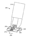
도 2a, 도 2b, 및 도 2c는 3개의 상이한 크기의 부분 절취부 패널에 사용하기 위해 위치된 본 발명에 따른 노즐의 단면도이다.
도 3은 본 발명에 따른 방법에 의해, 본 발명에 따른 노즐로부터 도포된 저밀도 공극 충전재를 하나의 절취부 표면 상에 담지(bearing)하고 있는 부분 절취부 벌집형 패널의 사진이다.Figures 1a, 1b, 1c and 1d are views of a nozzle according to the invention.
Figures 2a, 2b, and 2c are cross-sectional views of a nozzle according to the present invention positioned for use with three differently sized partial cut-out panels.
Figure 3 is a photograph of a partially cut-off honeycomb panel bearing a low density void filler applied from a nozzle according to the invention on one cut surface by the method according to the invention.
본 발명은 패널 내의 부분 절취부의 에지 상에 경화성 수지를 도포하기 위한 노즐 및 패널 내의 부분 절취부의 에지 상에 경화성 수지를 도포하는 방법에 관한 것이다. 부분 절취부는 패널의 전체 폭을 통하여 절취하지 않은, 채널 절취부, 라우터(router) 절취부, 플런지 절취부, 또는 패널 에지를 노출시키는 임의의 절취부를 포함할 수 있다. 일부 실시예에서, 부분 절취부는 절취부의 영역에서, 하부 표면 층을 그대로 남기면서, 패널의 상부 표면 층 및 하나 이상의 내부 층의 사실상 모두를 제거한다. 일부 실시예에서, 패널의 내부 층은 상부 표면 층에 대해 언더컷(undercut)된다.The present invention relates to a nozzle for applying a curable resin on the edge of the cut-out portion in the panel and a method for applying the curable resin on the edge of the cut-out portion in the panel. The cutout portion may include a channel cutout, a router cutout, a plunge cutout, or any cutout that exposes the panel edge, which is not cut through the entire width of the panel. In some embodiments, the partial cutout removes substantially all of the upper surface layer and one or more inner layers of the panel, leaving the lower surface layer intact, in the region of the cutout. In some embodiments, the inner layer of the panel is undercut with respect to the upper surface layer.
임의의 적합한 패널이 본 발명의 실시에서 사용될 수 있다. 전형적으로, 패널은 상부 표면 층, 적어도 하나의 코어 층, 및 하부 표면 층을 포함한다. 일부 실시예에서, 패널은 절취된 경우 공극 또는 울퉁불퉁한(ragged) 또는 불균일한 표면을 제공하는 코어 재료를 포함한다. 일부 실시예에서, 패널은 벌집형 지지 재료의 코어 층을 포함하는 벌집형 패널이다. 벌집형 지지 재료는 표준 벌집형 및 과팽창 벌집형을 포함한 임의의 적합한 지오메트리(geometry) 또는 재료일 수 있다. 적합한 재료에는 금속 또는 합금, 종이 또는 카드지, 플라스틱 수지, 섬유, 또는 이들의 조합, 예컨대, 유리섬유 또는 NOMEX® 아라미드 수지-처리된 종이가 포함될 수 있다. 일부 실시예에서, 패널은 발포체 재료의 하나 이상의 층을 포함하는 코어를 포함하는 발포체 코어 패널이다. 표면 층은 단일 층일 수 있거나, 또는 둘 이상의 겹(ply)으로 구성될 수 있다. 표면 층은 알루미늄 또는 다른 금속 또는 합금, 플라스틱 수지, 예컨대, 유리 섬유가 선택적으로 포함된 페놀 수지, 아라미드 천, 예컨대, KEVLAR®, 종이, 수지, 또는 베니어판(veneer) 중 하나 이상을 포함할 수 있는 임의의 적합한 재료의 것일 수 있다.Any suitable panel may be used in the practice of the present invention. Typically, the panel comprises a top surface layer, at least one core layer, and a bottom surface layer. In some embodiments, the panel includes a core material that, when cut, provides voids or ragged or uneven surfaces. In some embodiments, the panel is a honeycomb panel comprising a core layer of a honeycomb support material. The honeycomb support material may be any suitable geometry or material including standard honeycombs and overexpansion honeycombs. Suitable materials may include metals or alloys, paper or card stock, plastic resins, fibers, or combinations thereof, such as glass fibers or NOMEX® aramid resin-treated paper. In some embodiments, the panel is a foam core panel comprising a core comprising at least one layer of foam material. The surface layer can be a single layer, or it can consist of two or more ply. The surface layer may comprise one or more of aluminum or other metals or alloys, plastic resins such as phenolic resins optionally containing glass fibers, aramid fabrics such as KEVLAR, paper, resin, or veneer But may be of any suitable material.
도 3은 상부 표면 층(110)을 포함하는 벌집형 코어 패널(100)의 사진이다. 부분 절취부(120)는 하부 표면 층(140) 및 벌집형 코어(130)를 노출시킨다. 경화성 수지, 이 경우에는, 저밀도 공극 충전 수지가 본 발명의 노즐 및 방법을 사용하여 부분 절취부의 하나의 에지에 도포되었다. 수지는 제 위치에서 경화되도록 허용되어 에지 충전부(150)를 형성하였다. 부분 절취부(120)는 언더컷(125)을 포함하는데, 여기서 벌집형 코어(130)는 상부 표면 층(110)에 대해 언더컷된다.3 is a photograph of a
임의의 적합한 경화성 수지가 본 발명의 실시에 이용될 수 있다. 적합한 재료에는 1-파트(one-part) 또는 2-파트 접착제를 포함하는 접착제, 및 저밀도 공극 충전재를 포함하는 공극 충전재 재료가 포함될 수 있다.Any suitable curable resin may be used in the practice of the present invention. Suitable materials may include an adhesive comprising a one-part or two-part adhesive, and a void filler material comprising a low density void filler.
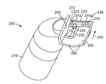
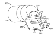
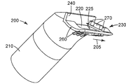
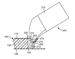
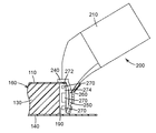
도 1a 내지 도 1d 및 도 2a 내지 도 2c는 본 발명에 따른 노즐(200)의 소정 실시예를 도시한다. 화살표(205)는 사용 중인 노즐의 이동 방향, 본 명세서에서 "횡축"을 나타낸다. 도 2a 내지 도 2c에서, 사용 중인 노즐의 이동 방향(횡축)은 관찰자를 향해, 지면(page)에 직교한다. 본 명세서에서 사용되는 바와 같이, "수직축"은, 도 2a 내지 도 2c에 도시된 바와 같이, 노즐이 사용을 위해 패널 옆에 위치될 때 패널에 직교하는 축이다. 도 2a는 두께가 1/4"(0.64 cm)인 부분 절취부 패널(160)에 사용하기 위해 위치된 본 발명에 따른 노즐(200)의 일 실시예를 도시한다. 도 2b는 두께가 1/2"(1.27 cm)인 부분 절취부 패널(170)에 사용하기 위해 위치된 본 발명에 따른 노즐(200)의 일 실시예를 도시한다. 도 2c는 두께가 5/8"(1.59 cm)인 부분 절취부 패널(180)에 사용하기 위해 위치된 본 발명에 따른 노즐(200)의 일 실시예를 도시한다. 패널(160, 170, 180) 각각은 상부 표면 층(110), 하부 표면 층(140) 및 벌집형 코어(130)를 포함한다. 도 2a 내지 도 2c의 각각에서, 벌집형 코어(130)는 상부 표면 층(110)에 대해 언더컷되어 있어서, 갭(190)을 남기고, 하부 표면 층(140)은 부분 절취부의 부위에서 절취되지 않는다.FIGS. 1A through 1D and FIGS. 2A through 2C illustrate certain embodiments of a
도 1a 내지 도 1d 및 도 2a 내지 도 2c를 참조하면, 본 발명에 따른 노즐(200)은 경화성 수지(미도시)를 수용하기 위해 경화성 수지 분배 장치(미도시)와 결합하도록 구성된 커넥터 부분(210)을 포함한다. 커넥터 부분(210)은 임의의 적합한 경화성 수지 분배 장치와 결합하도록 구성될 수 있다. 적합한 경화성 수지 분배 장치는 펌프, 튜브, 또는 건(gun)의 출력부, 또는 혼합 헤드의 출력부를 포함할 수 있다. 일부 실시예에서, 혼합 헤드는 10 또는 13 mm의 외경을 갖고, 그에 따라서, 커넥터 부분(210)은 그러한 장치에 대한 마찰 끼워맞춤을 위해 구성된 10 또는 13 mm의 내경을 가질 수 있다. 일부 실시예에서, 혼합 헤드는 다각형 프로파일을 갖고, 그에 따라서, 커넥터 부분(210)은 상응하는 다각형 프로파일을 가질 수 있다. 다양한 실시예에서, 커넥터 부분(210)은 마찰 끼워맞춤, 나사 연결, 바요넷(bayonet) 장착, 또는 유사한 메커니즘에 의해 경화성 수지 분배 장치와 결합하도록 구성될 수 있다.Referring to FIGS. 1A to 1D and 2A to 2C, a
통로(220)는 경화성 수지(미도시)가 도포 헤드(230) 내에 들어가는 것을 허용한다. 일부 실시예에서, 통로(220)는 증가된 수지 유동을 허용하도록 횡방향으로 길다. 일부 실시예에서, 통로(220)는 도포 헤드(230) 내에 들어가는 수지를 사용 동안 노즐(200)의 이동 방향에 반대 방향으로 향하게 하는 만곡된 출구 리지(ridge)(225)를 포함한다. 일부 실시예에서, 통로(220)는 도포 헤드(230)의 마감 벽(250)을 통과한다.The
커넥터 부분(210)은 임의의 적합한 각도로 도포 헤드(230)와 결합할 수 있다. 도 1a 내지 도 1d 및 도 2a 내지 도 2c에 도시된 바와 같은 일부 실시예에서, 커넥터 부분(210)은 (수직축에 대해) 수직방향으로부터 대략 45도로 그리고 (횡축에 대해) 횡방향으로부터 90도로 도포 헤드(230)와 결합할 수 있다. 일부 실시예에서, 커넥터 부분(210)은 수직방향으로부터 0도 내지 90도 그리고 횡방향으로부터 0도 내지 180도의 각도로 도포 헤드(230)와 결합할 수 있다. 도포를 수동으로 하도록 구성된 일부 실시예에서, 커넥터 부분(210)은 수직방향으로부터 15도 내지 75도 그리고 횡방향으로부터 15도 내지 165도의 각도로 도포 헤드(230)와 결합한다. 도포를 자동으로 하도록 구성된 일부 실시예에서, 커넥터 부분(210)은 수직방향으로부터 0도 내지 45도 그리고 횡방향으로부터 45도 내지 135도의 각도로 도포 헤드(230)와 결합한다.The
도포 헤드(230)는 지지 벽(240)을 포함한다. 사용 중에, 지지 벽(240)은 상부 표면 층(110)에 평행한 평면이고 그 위에 놓여서 노즐(200)의 접촉, 정렬 및 지지를 제공한다. 지지 벽(240)은 노즐(200)의 추가 접촉, 정렬 및 지지를 제공하기 위해 상부 표면 층(110)의 외부 에지 위에 놓이는 각을 형성하도록 에지를 따라서 마감 벽(250)과 결합한다. 전형적인 실시예에서, "지지 벽"은, 노즐이 수지를 패널에 도포하기 위해 사용 중에 있을 때, 패널의 일부와 접촉 상태에 있을 수 있고 그에 평행한 평면일 수 있는 노즐 구성요소를 의미한다. 일부 실시예에서, "지지 벽"은, 노즐이 수지를 패널에 도포하기 위해 사용 중에 있을 때, 패널의 외부 에지 위에 놓이는 마감 벽(250)과의 일정 각을 형성할 수 있는 노즐 구성요소를 의미할 수 있다. 일부 실시예에서, 도포 헤드(230)는 단일 지지 벽(240); 즉, 단 하나의 지지 벽(240)을 포함한다. 일부 실시예에서, 도포 헤드(230)는, 사용 동안, 하부 표면 층과 접촉을 이루는 마감 벽(250) 이외에는 어떠한 구성요소도 포함하지 않는다. 일부 실시예에서, 도포 헤드(230)는, 사용 동안, 지지 벽(240) 및 마감 벽(250) 이외에 패널과 접촉을 이루는 어떠한 구성요소도 포함하지 않는다.The
도 1a 내지 도 1d 및 도 2a 내지 도 2c에 도시된 바와 같은 일부 실시예에서, 마감 벽(250)의 후단 에지는, 도포 후에 도포된 수지(미도시)에 매끄럽게 만곡된 마감을 제공하기 위해 패널을 향하여 매끄럽게 만곡되어 있다. 일부 실시예에서, 마감 벽(250)의 후단 에지의 곡선 반경이 일정하지만, 다른 실시예에서, 마감 벽(250)의 후단 에지의 곡선 반경은 후단 에지의 길이에 걸쳐 가변한다. 일부 실시예에서, 마감 벽(250)의 매끄럽게 만곡된 후단 에지의 곡선 반경은 곡선 전체에 걸쳐 1.0 내지 7.0 cm, 일부 실시예에서는, 1.5 내지 7.0 cm, 일부 실시예에서는, 1.5 내지 5.0 cm, 그리고 일부 실시예에서는, 1.5 내지 3.0 cm로 유지된다. 본 명세서에서 사용되는 바와 같이, "곡선 반경"은 만곡된 마감 벽(250)의 내부 면에 관한 것이고 횡축에 직교하는 평면에 존재하는 곡선에 대해 측정된다. 일부 실시예에서, 지지 벽(240)은 에지를 따라서 직각으로 마감 벽(250)과 결합한다. 다른 실시예(미도시)에서, 마감 벽(250)의 후단 에지는, 도포 후에 도포된 수지(미도시)에 평평한 마감을 제공하도록 직선일 수 있다. 도 1a 내지 도 1d 및 도 2a 내지 도 2c에 도시된 바와 같은 일부 실시예에서, 지지 벽(240)은 90도 이상, 일부 실시예에서는, 92도 초과, 그리고 일부 실시예에서는, 94도 초과의 각도로 에지를 따라서 마감 벽(250)과 결합한다. 일부 실시예에서, 지지 벽(240)은 90도 이상 및 120도 미만; 일부 실시예에서는, 92도 초과 및 120도 미만, 그리고 일부 실시예에서는, 94도 초과 및 120도 미만의 각도로 에지를 따라서 마감 벽(250)과 결합한다. 일부 실시예에서, 마감 벽(250)은 스코어링(260)을 포함하여, 더 얇은 패널에 노즐(200)을 사용하기 위해 사용자가 마감 벽(250)의 원위 부분을 파단시킬 수 있게 한다. 도 1a 내지 도 1d 및 도 2a 내지 도 2c에 도시된 실시예에서, 노즐(200)은 도 2a에 도시된 바와 같은 1/4"(0.64 cm) 패널 또는 도 2b에 도시된 바와 같은 1/2"(1.27 cm) 패널에 사용하기 위해 스코어링되거나, 또는 도 2c에 도시된 바와 같은 5/8"(1.59 cm) 패널에 그대로 사용될 수 있다. 마감 벽(250)과 지지 벽(240) 사이에 형성된 각으로부터 마감 벽(250)의 단부까지 수직축을 따라서 측정된 마감 벽(250)의 길이는 상부 표면 층과 패널의 코어의 합해진 폭과 대략 동일하다.In some embodiments, such as those shown in Figs. IA-ID and Figs. 2A-2C, the trailing edge of the
도 1a 내지 도 1d 및 도 2a 내지 도 2c에 도시된 바와 같은 일부 실시예에서, 마감 벽(250)의 선단 에지는 도포된 수지의 마감 벽(250)의 선단 에지를 지나는 이동을 방해하는 차단 벽(270)을 포함한다. 일부 실시예에서, 차단 벽(270)의 선단 측은 벌집형 코어(130)와 같은 코어 재료와의 간섭을 최소화하도록 경사진다. 일부 실시예에서, 차단 벽(270)의 높이는 코어 재료와의 접촉을 피하기 위해 벌집형 코어(130)와 같은 코어 재료의 언더컷보다 낮다. 차단 벽(270)은 상부 표면 층(110)에 대해 여유를 제공하기 위해 갭(272)을 포함한다. 일부 실시예에서, 차단 벽(270)은 또한 스코어링(260)에 상응하는 갭(274)을 포함한다.In some embodiments, as shown in FIGS. 1A-1D and 2A-2C, the leading edge of the
본 발명에 따른 노즐은 임의의 적합한 재료로 제조될 수 있다. 적합한 재료에는 세라믹, 금속 또는 플라스틱 수지, 예컨대, ABS, 아크릴, 폴리에테르아미드, 예컨대, ULTEM™을 잠재적으로 포함하고 섬유 또는 충전재가 선택적으로 통합된 수지가 포함될 수 있다. 일부 실시예에서, 노즐 재료는 제조, 사용, 및 세척 동안 노즐 내의 경화성 수지의 관찰을 허용하도록 광학적으로 투명하거나 또는 반투명하다. 본 발명에 따른 노즐은 임의의 적합한 공정에 의해 제조될 수 있다. 적합한 공정에는 기계가공, 애디티브 공정(additive process), 예컨대, 3D 인쇄, 성형 공정, 예컨대, 사출 성형이 포함될 수 있다. 일부 실시예에서, 본 발명에 따른 노즐은 단일 편의 일체로 형성된 물품이다. 일부 실시예에서, 본 발명에 따른 노즐은 경화성 수지 분배 장치와 일체로 형성되거나 그에 영구적으로 부착된다.The nozzle according to the present invention can be made of any suitable material. Suitable materials may include resins that potentially contain ceramic, metal or plastic resins, such as ABS, acrylics, polyether amides, such as ULTEM (TM), and fibers or fillers optionally incorporated. In some embodiments, the nozzle material is optically transparent or translucent to allow observation of the curable resin in the nozzle during manufacture, use, and cleaning. The nozzle according to the present invention can be manufactured by any suitable process. Suitable processes may include machining, additive processes such as 3D printing, forming processes, such as injection molding. In some embodiments, the nozzle according to the present invention is an article formed integrally with a single piece. In some embodiments, the nozzle according to the present invention is formed integrally with or attached to the curable resin dispensing apparatus permanently.
도 2a 내지 도 2c를 참조하면, 본 발명에 따른 방법에서, 본 발명에 따른 노즐(200)의 커넥터 부분(210)은 수지 분배 디바이스(미도시)의 출력부와 연결된다. 노즐(200)의 도포 헤드(230)는 패널(160, 170, 또는 180) 내의 부분 절취부의 에지와 접촉하게 되어, 지지 벽(240)이 노즐(200)의 접촉, 정렬 및 지지를 제공하기 위해 상부 표면 층(110)에 평행한 평면이고 그 위에 놓이도록, 또는 지지 벽(240)과 마감 벽(250) 사이에 형성된 각이 노즐(200)의 접촉, 정렬 및 지지를 제공하기 위해 상부 표면 층(110)의 외부 에지 위에 놓이도록, 또는 둘 모두가 되도록 한다. 경화성 수지(미도시)는, 수지를 부분 절취부 에지에 도포하기 위해 패널에 대해 횡방향으로 노즐이 이동되는 동안, 수지 분배 디바이스로부터 노즐(200)을 통하여 패널(160, 170, 또는 180)의 부분 절취부 에지로 분배된다. 패널에 대한 노즐의 이동은 노즐의 이동, 패널의 이동, 또는 둘 모두에 의해 달성될 수 있다는 것이 이해되어야 한다. 경화성 수지는 경화가 허용되거나 야기된다. 수지의 분배는 수동식 및 기계식 방법을 포함하는 임의의 적합한 방법에 의해 유발될 수 있고, 인간에 의한 또는 자동화된 방법을 포함하는 임의의 적합한 방법에 의해 제어될 수 있다. 패널 및 노즐의 지지 및 이동은 수동식 및 기계식 방법을 포함하는 임의의 적합한 방법에 의해 달성될 수 있고, 인간에 의한 또는 자동화된 방법을 포함하는 임의의 적합한 방법에 의해 제어될 수 있다.Referring to FIGS. 2A-2C, in the method according to the present invention, the
본 개시 내용의 다양한 변형 및 변경이 본 개시 내용의 범위 및 원리로부터 벗어남이 없이 당업자에게 명백해질 것이며, 본 개시 내용이 본 명세서에서 전술된 예시적인 실시예로 부당하게 제한되지 않는다는 것을 이해하여야 한다.It should be understood that various changes and modifications to the present disclosure will become apparent to those skilled in the art without departing from the scope and spirit of the present disclosure and that the present disclosure is not to be unduly limited to the exemplary embodiments described hereinabove.
Claims (14)
노즐은 커넥터 부분 및 도포 헤드를 포함하고, 커넥터 부분은 수지 분배 디바이스로부터 경화성 수지를 수용하도록 그리고 경화성 수지를 도포 헤드로 전달하도록 구성되고, 도포 헤드는
a) 지지 벽, 및
b) 90도 이상 및 120도 미만의 각도로 에지를 따라서 지지 벽과 결합하는 마감 벽(finish wall)을 포함하고,
커넥터 부분은 지지 벽과 마감 벽 사이에 형성된 각의 내부의 도포 헤드에 경화성 수지를 전달하도록 구성된 노즐.1. A nozzle for applying a curable resin on an edge of a partial cut in a panel,
The nozzle comprising a connector portion and an application head, the connector portion being configured to receive the curable resin from the resin dispensing device and to transfer the curable resin to the application head,
a) a support wall, and
b) a finish wall engaging the support wall along the edge at an angle of greater than 90 degrees and less than 120 degrees,
Wherein the connector portion is configured to deliver the curable resin to an internal application head of the angle formed between the support wall and the finish wall.
a) 제1항 내지 제8항 중 어느 한 항에 따른 노즐의 커넥터 부분을 수지 분배 디바이스의 출력부와 연결시키는 단계;
b) 상기 노즐의 도포 헤드를 패널 내의 부분 절취부의 에지와 접촉시키는 단계; 및
c) 수지를 부분 절취부 에지에 도포하기 위해 패널에 대해 횡방향으로 노즐이 이동되는 동안 노즐을 통하여 패널의 부분 절취부 에지로 경화성 수지를 분배하는 단계를 포함하는 방법.A method of applying a curable resin on an edge of a cut-out portion in a panel,
a) connecting a connector portion of a nozzle according to any one of Claims 1 to 8 with an output of a resin distribution device;
b) contacting the application head of the nozzle with the edge of the cut-out portion in the panel; And
c) dispensing the curable resin through the nozzle to the partially cut edge of the panel while the nozzle is moved transversely with respect to the panel to apply the resin to the partially cut edge.
13. The method according to any one of claims 9 to 12, wherein the curable resin is a low density void filler.
Applications Claiming Priority (3)
| Application Number | Priority Date | Filing Date | Title |
|---|---|---|---|
| US201562132810P | 2015-03-13 | 2015-03-13 | |
| US62/132,810 | 2015-03-13 | ||
| PCT/US2016/020806 WO2016148937A1 (en) | 2015-03-13 | 2016-03-04 | Nozzle tip and method for dispensing onto a partial cut panel |
Publications (1)
| Publication Number | Publication Date |
|---|---|
| KR20170128425A true KR20170128425A (en) | 2017-11-22 |
Family
ID=55588585
Family Applications (1)
| Application Number | Title | Priority Date | Filing Date |
|---|---|---|---|
| KR1020177028652A KR20170128425A (en) | 2015-03-13 | 2016-03-04 | Nozzle tips and methods for dispensing on partially cut-out panels |
Country Status (8)
| Country | Link |
|---|---|
| US (1) | US10549308B2 (en) |
| EP (1) | EP3268134B1 (en) |
| JP (1) | JP2018510771A (en) |
| KR (1) | KR20170128425A (en) |
| CN (1) | CN107405645A (en) |
| BR (1) | BR112017019572A2 (en) |
| CA (1) | CA2978079A1 (en) |
| WO (1) | WO2016148937A1 (en) |
Families Citing this family (3)
| Publication number | Priority date | Publication date | Assignee | Title |
|---|---|---|---|---|
| KR20170130459A (en) | 2015-03-13 | 2017-11-28 | 쓰리엠 이노베이티브 프로퍼티즈 컴파니 | Nozzle tip and method for dispensing on panel edges |
| KR20170127006A (en) | 2015-03-13 | 2017-11-20 | 쓰리엠 이노베이티브 프로퍼티즈 컴파니 | Nozzle tips and methods for filling honeycomb panels for reinforcement |
| CN114146846B (en) * | 2021-12-13 | 2023-04-21 | 清远市快地新型建材有限公司 | Painting device for PVC floor |
Family Cites Families (25)
| Publication number | Priority date | Publication date | Assignee | Title |
|---|---|---|---|---|
| US796246A (en) * | 1905-03-15 | 1905-08-01 | John Printz | Glazier's tool. |
| NL287460A (en) | 1962-01-17 | |||
| US3807351A (en) | 1971-03-19 | 1974-04-30 | A Tuberman | Edger and feed system therefor |
| US4378170A (en) | 1980-11-24 | 1983-03-29 | The Boeing Company | Panel edge potter |
| EP0139645A1 (en) | 1983-04-22 | 1985-05-08 | The Boeing Company | Edge finishing tool |
| ZA873937B (en) | 1986-06-12 | 1987-12-02 | A.H. Robins Company, Incorporated | Lip medication applicator |
| GB2229655B (en) * | 1989-03-29 | 1992-11-11 | Evode Ltd | Extrusion nozzle distribution head |
| CA2051183C (en) | 1991-09-11 | 1994-09-13 | Maurice L. Despins | Applicator tip for dispensing liquid adhesive to seam adjacent layers of floorcovering sheeting |
| US5471704A (en) * | 1993-04-28 | 1995-12-05 | Woolley; Edward G. | Caulking tool |
| CA2254295A1 (en) | 1998-11-30 | 2000-05-30 | Matthew Gordon Charles Kennedy | Resin applicator |
| JP2000213159A (en) * | 1999-01-22 | 2000-08-02 | Sumitomo Forestry Co Ltd | Nozzle for filling sealant |
| GB2352989B (en) | 1999-08-03 | 2003-11-12 | Inbis Ltd | Nozzle |
| US6276858B1 (en) | 1999-11-29 | 2001-08-21 | Matthew Gordon Charles Kennedy | Resin applicator |
| DE20319881U1 (en) * | 2003-12-19 | 2004-03-11 | Xella Trockenbau - Systeme Gmbh | Nozzle for application of paste substances has track positioning element forming first boundary wall of outlet orifice, while at least one second track positioning element is formed on outlet orifice and forms second boundary wall |
| EP1749586A1 (en) * | 2005-08-03 | 2007-02-07 | Collano AG | Device and procedure for controlling the width and/or the density of a fluid mass |
| FI6975U1 (en) | 2005-09-09 | 2006-02-20 | Stick Tech Oy | Dental hand instrument, dental instrument tip and dental arrangement |
| WO2009009840A1 (en) | 2007-07-19 | 2009-01-22 | Aaron Luvara | Cornice cement applicator |
| US20090294489A1 (en) | 2008-06-02 | 2009-12-03 | Gene Keohan | Apparatus for applying filler material and method of using same |
| ITMO20080171A1 (en) * | 2008-06-04 | 2009-12-05 | Lameplast Spa | CONTAINER FOR FLUID PRODUCTS, PARTICULARLY CREAMS, POMATE, PASTE, LOTIONS FOR MEDICAL, PHARMACEUTICAL OR COSMETIC USE |
| DE102008047234B4 (en) | 2008-09-12 | 2018-12-06 | Henkel Ag & Co. Kgaa | Repair nozzle and repair system |
| FR2970427B1 (en) * | 2011-01-19 | 2015-06-19 | Airbus Operations Sas | DEVICE FOR APPLYING A PROTECTIVE MATERIAL ON THE SONG OF A WORKPIECE |
| JP5922539B2 (en) | 2012-09-13 | 2016-05-24 | 三菱重工業株式会社 | Sealant molding nozzle, sealant molding device, sealant molding method |
| DE202014001032U1 (en) * | 2014-02-05 | 2014-02-13 | Fermacell Gmbh | Nozzle for applying pasty substances |
| KR20170130459A (en) | 2015-03-13 | 2017-11-28 | 쓰리엠 이노베이티브 프로퍼티즈 컴파니 | Nozzle tip and method for dispensing on panel edges |
| KR20170127006A (en) | 2015-03-13 | 2017-11-20 | 쓰리엠 이노베이티브 프로퍼티즈 컴파니 | Nozzle tips and methods for filling honeycomb panels for reinforcement |
-
2016
- 2016-03-04 KR KR1020177028652A patent/KR20170128425A/en unknown
- 2016-03-04 EP EP16711435.4A patent/EP3268134B1/en not_active Not-in-force
- 2016-03-04 CN CN201680014705.6A patent/CN107405645A/en active Pending
- 2016-03-04 BR BR112017019572A patent/BR112017019572A2/en not_active Application Discontinuation
- 2016-03-04 WO PCT/US2016/020806 patent/WO2016148937A1/en active Application Filing
- 2016-03-04 CA CA2978079A patent/CA2978079A1/en not_active Abandoned
- 2016-03-04 US US15/548,668 patent/US10549308B2/en active Active
- 2016-03-04 JP JP2017548163A patent/JP2018510771A/en not_active Withdrawn
Also Published As
| Publication number | Publication date |
|---|---|
| BR112017019572A2 (en) | 2018-05-02 |
| JP2018510771A (en) | 2018-04-19 |
| CA2978079A1 (en) | 2016-09-22 |
| EP3268134B1 (en) | 2019-01-23 |
| CN107405645A (en) | 2017-11-28 |
| EP3268134A1 (en) | 2018-01-17 |
| US20180015495A1 (en) | 2018-01-18 |
| WO2016148937A1 (en) | 2016-09-22 |
| US10549308B2 (en) | 2020-02-04 |
Similar Documents
| Publication | Publication Date | Title |
|---|---|---|
| US11027307B2 (en) | Nozzle tip and method for dispensing onto a panel edge | |
| US10717214B2 (en) | Nozzle tip and method for filling honeycomb panel for reinforcement | |
| KR20170128425A (en) | Nozzle tips and methods for dispensing on partially cut-out panels | |
| US20110155854A1 (en) | Method for the manufacture of a fiber-reinforced component, device for implementing the method, and fiber-reinforced component | |
| DE102012021921B4 (en) | Method for producing an optical lens element, in particular a headlight lens for a motor vehicle headlight | |
| JPS6235644B2 (en) | ||
| JP7289504B2 (en) | film applicator | |
| EP2910359B1 (en) | Method and apparatus for making preformed seals | |
| US20140196837A1 (en) | Method of integrally forming ribs in a composite panel | |
| CN109421919A (en) | Aircraft leading edge method for producing panel, corresponding leading edge panel, leading edge and aircraft | |
| KR101627249B1 (en) | Shutter panels and manufacturing method of them | |
| JP7451018B2 (en) | Light control film manufacturing device and light control film manufactured thereby | |
| US8798432B2 (en) | Fabrication of a laminated optical wedge | |
| US11826972B2 (en) | Molded laminated structure with negative draft angles and associated methods of manufacturing | |
| CN201693637U (en) | Veneer trimming structure | |
| JP2007163960A (en) | Optical device, optical unit, manufacturing method of optical device and manufacturing method of optical unit | |
| TWM434229U (en) | Reinforcement tool for micro machining cracks of hard and brittle material |