KR20170120032A - Directional antenna module - Google Patents
Directional antenna module Download PDFInfo
- Publication number
- KR20170120032A KR20170120032A KR1020170049185A KR20170049185A KR20170120032A KR 20170120032 A KR20170120032 A KR 20170120032A KR 1020170049185 A KR1020170049185 A KR 1020170049185A KR 20170049185 A KR20170049185 A KR 20170049185A KR 20170120032 A KR20170120032 A KR 20170120032A
- Authority
- KR
- South Korea
- Prior art keywords
- antenna
- antenna module
- directional antenna
- module
- directional
- Prior art date
Links
Images


Classifications
-
- H—ELECTRICITY
- H01—ELECTRIC ELEMENTS
- H01Q—ANTENNAS, i.e. RADIO AERIALS
- H01Q9/00—Electrically-short antennas having dimensions not more than twice the operating wavelength and consisting of conductive active radiating elements
- H01Q9/04—Resonant antennas
- H01Q9/16—Resonant antennas with feed intermediate between the extremities of the antenna, e.g. centre-fed dipole
-
- H—ELECTRICITY
- H01—ELECTRIC ELEMENTS
- H01Q—ANTENNAS, i.e. RADIO AERIALS
- H01Q3/00—Arrangements for changing or varying the orientation or the shape of the directional pattern of the waves radiated from an antenna or antenna system
- H01Q3/24—Arrangements for changing or varying the orientation or the shape of the directional pattern of the waves radiated from an antenna or antenna system varying the orientation by switching energy from one active radiating element to another, e.g. for beam switching
-
- G—PHYSICS
- G01—MEASURING; TESTING
- G01S—RADIO DIRECTION-FINDING; RADIO NAVIGATION; DETERMINING DISTANCE OR VELOCITY BY USE OF RADIO WAVES; LOCATING OR PRESENCE-DETECTING BY USE OF THE REFLECTION OR RERADIATION OF RADIO WAVES; ANALOGOUS ARRANGEMENTS USING OTHER WAVES
- G01S3/00—Direction-finders for determining the direction from which infrasonic, sonic, ultrasonic, or electromagnetic waves, or particle emission, not having a directional significance, are being received
- G01S3/02—Direction-finders for determining the direction from which infrasonic, sonic, ultrasonic, or electromagnetic waves, or particle emission, not having a directional significance, are being received using radio waves
- G01S3/14—Systems for determining direction or deviation from predetermined direction
- G01S3/38—Systems for determining direction or deviation from predetermined direction using adjustment of real or effective orientation of directivity characteristic of an antenna or an antenna system to give a desired condition of signal derived from that antenna or antenna system, e.g. to give a maximum or minimum signal
- G01S3/44—Systems for determining direction or deviation from predetermined direction using adjustment of real or effective orientation of directivity characteristic of an antenna or an antenna system to give a desired condition of signal derived from that antenna or antenna system, e.g. to give a maximum or minimum signal the adjustment being varied periodically or continuously until it is halted automatically when the desired condition is attained
-
- G—PHYSICS
- G01—MEASURING; TESTING
- G01S—RADIO DIRECTION-FINDING; RADIO NAVIGATION; DETERMINING DISTANCE OR VELOCITY BY USE OF RADIO WAVES; LOCATING OR PRESENCE-DETECTING BY USE OF THE REFLECTION OR RERADIATION OF RADIO WAVES; ANALOGOUS ARRANGEMENTS USING OTHER WAVES
- G01S3/00—Direction-finders for determining the direction from which infrasonic, sonic, ultrasonic, or electromagnetic waves, or particle emission, not having a directional significance, are being received
- G01S3/02—Direction-finders for determining the direction from which infrasonic, sonic, ultrasonic, or electromagnetic waves, or particle emission, not having a directional significance, are being received using radio waves
- G01S3/14—Systems for determining direction or deviation from predetermined direction
- G01S3/16—Systems for determining direction or deviation from predetermined direction using amplitude comparison of signals derived sequentially from receiving antennas or antenna systems having differently-oriented directivity characteristics or from an antenna system having periodically-varied orientation of directivity characteristic
- G01S3/22—Systems for determining direction or deviation from predetermined direction using amplitude comparison of signals derived sequentially from receiving antennas or antenna systems having differently-oriented directivity characteristics or from an antenna system having periodically-varied orientation of directivity characteristic derived from different combinations of signals from separate antennas, e.g. comparing sum with difference
-
- G—PHYSICS
- G01—MEASURING; TESTING
- G01S—RADIO DIRECTION-FINDING; RADIO NAVIGATION; DETERMINING DISTANCE OR VELOCITY BY USE OF RADIO WAVES; LOCATING OR PRESENCE-DETECTING BY USE OF THE REFLECTION OR RERADIATION OF RADIO WAVES; ANALOGOUS ARRANGEMENTS USING OTHER WAVES
- G01S3/00—Direction-finders for determining the direction from which infrasonic, sonic, ultrasonic, or electromagnetic waves, or particle emission, not having a directional significance, are being received
- G01S3/02—Direction-finders for determining the direction from which infrasonic, sonic, ultrasonic, or electromagnetic waves, or particle emission, not having a directional significance, are being received using radio waves
- G01S3/14—Systems for determining direction or deviation from predetermined direction
- G01S3/38—Systems for determining direction or deviation from predetermined direction using adjustment of real or effective orientation of directivity characteristic of an antenna or an antenna system to give a desired condition of signal derived from that antenna or antenna system, e.g. to give a maximum or minimum signal
- G01S3/40—Systems for determining direction or deviation from predetermined direction using adjustment of real or effective orientation of directivity characteristic of an antenna or an antenna system to give a desired condition of signal derived from that antenna or antenna system, e.g. to give a maximum or minimum signal adjusting orientation of a single directivity characteristic to produce maximum or minimum signal, e.g. rotatable loop antenna or equivalent goniometer system
-
- H—ELECTRICITY
- H01—ELECTRIC ELEMENTS
- H01Q—ANTENNAS, i.e. RADIO AERIALS
- H01Q1/00—Details of, or arrangements associated with, antennas
- H01Q1/36—Structural form of radiating elements, e.g. cone, spiral, umbrella; Particular materials used therewith
- H01Q1/38—Structural form of radiating elements, e.g. cone, spiral, umbrella; Particular materials used therewith formed by a conductive layer on an insulating support
-
- H—ELECTRICITY
- H01—ELECTRIC ELEMENTS
- H01Q—ANTENNAS, i.e. RADIO AERIALS
- H01Q1/00—Details of, or arrangements associated with, antennas
- H01Q1/48—Earthing means; Earth screens; Counterpoises
-
- H—ELECTRICITY
- H01—ELECTRIC ELEMENTS
- H01Q—ANTENNAS, i.e. RADIO AERIALS
- H01Q15/00—Devices for reflection, refraction, diffraction or polarisation of waves radiated from an antenna, e.g. quasi-optical devices
- H01Q15/14—Reflecting surfaces; Equivalent structures
-
- H—ELECTRICITY
- H01—ELECTRIC ELEMENTS
- H01Q—ANTENNAS, i.e. RADIO AERIALS
- H01Q21/00—Antenna arrays or systems
- H01Q21/0087—Apparatus or processes specially adapted for manufacturing antenna arrays
-
- H—ELECTRICITY
- H01—ELECTRIC ELEMENTS
- H01Q—ANTENNAS, i.e. RADIO AERIALS
- H01Q21/00—Antenna arrays or systems
- H01Q21/06—Arrays of individually energised antenna units similarly polarised and spaced apart
- H01Q21/061—Two dimensional planar arrays
- H01Q21/062—Two dimensional planar arrays using dipole aerials
-
- H—ELECTRICITY
- H01—ELECTRIC ELEMENTS
- H01Q—ANTENNAS, i.e. RADIO AERIALS
- H01Q25/00—Antennas or antenna systems providing at least two radiating patterns
- H01Q25/02—Antennas or antenna systems providing at least two radiating patterns providing sum and difference patterns
-
- H—ELECTRICITY
- H01—ELECTRIC ELEMENTS
- H01Q—ANTENNAS, i.e. RADIO AERIALS
- H01Q7/00—Loop antennas with a substantially uniform current distribution around the loop and having a directional radiation pattern in a plane perpendicular to the plane of the loop
-
- H—ELECTRICITY
- H01—ELECTRIC ELEMENTS
- H01Q—ANTENNAS, i.e. RADIO AERIALS
- H01Q9/00—Electrically-short antennas having dimensions not more than twice the operating wavelength and consisting of conductive active radiating elements
- H01Q9/04—Resonant antennas
- H01Q9/06—Details
- H01Q9/065—Microstrip dipole antennas
-
- H—ELECTRICITY
- H01—ELECTRIC ELEMENTS
- H01Q—ANTENNAS, i.e. RADIO AERIALS
- H01Q3/00—Arrangements for changing or varying the orientation or the shape of the directional pattern of the waves radiated from an antenna or antenna system
- H01Q3/02—Arrangements for changing or varying the orientation or the shape of the directional pattern of the waves radiated from an antenna or antenna system using mechanical movement of antenna or antenna system as a whole
-
- H—ELECTRICITY
- H01—ELECTRIC ELEMENTS
- H01Q—ANTENNAS, i.e. RADIO AERIALS
- H01Q3/00—Arrangements for changing or varying the orientation or the shape of the directional pattern of the waves radiated from an antenna or antenna system
- H01Q3/26—Arrangements for changing or varying the orientation or the shape of the directional pattern of the waves radiated from an antenna or antenna system varying the relative phase or relative amplitude of energisation between two or more active radiating elements; varying the distribution of energy across a radiating aperture
- H01Q3/30—Arrangements for changing or varying the orientation or the shape of the directional pattern of the waves radiated from an antenna or antenna system varying the relative phase or relative amplitude of energisation between two or more active radiating elements; varying the distribution of energy across a radiating aperture varying the relative phase between the radiating elements of an array
- H01Q3/34—Arrangements for changing or varying the orientation or the shape of the directional pattern of the waves radiated from an antenna or antenna system varying the relative phase or relative amplitude of energisation between two or more active radiating elements; varying the distribution of energy across a radiating aperture varying the relative phase between the radiating elements of an array by electrical means
- H01Q3/40—Arrangements for changing or varying the orientation or the shape of the directional pattern of the waves radiated from an antenna or antenna system varying the relative phase or relative amplitude of energisation between two or more active radiating elements; varying the distribution of energy across a radiating aperture varying the relative phase between the radiating elements of an array by electrical means with phasing matrix
-
- H—ELECTRICITY
- H01—ELECTRIC ELEMENTS
- H01Q—ANTENNAS, i.e. RADIO AERIALS
- H01Q9/00—Electrically-short antennas having dimensions not more than twice the operating wavelength and consisting of conductive active radiating elements
- H01Q9/04—Resonant antennas
- H01Q9/16—Resonant antennas with feed intermediate between the extremities of the antenna, e.g. centre-fed dipole
- H01Q9/28—Conical, cylindrical, cage, strip, gauze, or like elements having an extended radiating surface; Elements comprising two conical surfaces having collinear axes and adjacent apices and fed by two-conductor transmission lines
- H01Q9/285—Planar dipole
Abstract
지향성 안테나 모듈(1)로서, 적어도 두 개의 안테나 소자들(3)을 갖는 적어도 하나의 안테나 어레이(2)로서, 상기 안테나 소자들(3)으로부터 수신되는 상기 안테나 신호들의 동상 합 신호(∑) 및 이상 합 신호(Δ)를 제공하는 180도 하이브리드에 연결되는 안테나 어레이(2); 방향 탐지 모드 제어 신호(DFM-CRTL)에 응답하여 상기 180도 하이브리드에 의해 출력되는 동상 합 신호(∑)와 이상 합 신호(Δ)의 사이를 스위칭하여 상기 지향성 안테나 모듈(1)의 안테나 모듈 출력(11)에서의 안테나 출력 신호를 제공하는 스위칭 소자(8)을 포함하는 지향성 안테나 모듈(1).1. A directional antenna module (1) comprising at least one antenna array (2) having at least two antenna elements (3), wherein the inphase sum signal (?) Of the antenna signals received from the antenna elements An antenna array (2) connected to a 180 degree hybrid providing an ideal sum signal (?); And outputs the resultant signals to the antenna module output (1) of the directional antenna module (1) by switching between the inphase sum signal (?) Output by the 180 degree hybrid in response to the direction detection mode control signal (DFM- And a switching element (8) providing an antenna output signal at the antenna (11).

Description
본 발명은 신호원의 방향 탐지 방법 및 장치에 관한 것이다.The present invention relates to a method and apparatus for detecting the direction of a signal source.
위성 내비게이션 시스템들의 이용 가능성으로 인해 내비게이션용 방향 탐지는 그 의미를 잃어가고 있으며, 특히 통신 장비의 휴대성이 증가함에 따라 신호원들의 위치를 결정하는 일이 중요해지고 있다. 방향 탐지가 중요한 또다른 이유는 확산 스펙트럼 기술들이 무선 통신에 더 많이 사용되기 때문이다. 이는 방향이 알려진 경우 스펙트럼의 성분들이 특정 방출기(emitter)에만 할당될 수 있음을 의미한다. 특히, 이러한 방사 내용들을 해석하는 것은 일반적으로 매우 어렵우므로, 방향 탐지는 무선 탐지에 있어 필수적인 단계이다. 무선 방향 탐지기(radio direction finder)의 과제는 전자기장 파라미터들을 측정하고 평가함으로써 방출기 신호원의 방향을 추정하는 것이다.Direction detection for navigation has lost its meaning due to the availability of satellite navigation systems, and it has become increasingly important to determine the location of the sources as the portability of communication equipment increases. Another reason why direction detection is important is that spread spectrum techniques are used more for wireless communications. This means that the components of the spectrum can only be assigned to a particular emitter if the direction is known. In particular, since it is generally very difficult to interpret these emissions, direction detection is an essential step in wireless detection. The challenge of a radio direction finder is to estimate the direction of the emitter signal source by measuring and evaluating the electromagnetic field parameters.
방향 탐지는 지향성 안테나들을 이용하여 수행될 수 있다. 방향을 기준으로 하여 기계식으로 피벗(pivot) 또는 회전되는 지향성 안테나의 수신 전압을 평가하는 것은 방향 탐지를 수행하는 가능한 방법이다. 여기서, 방위(bearing)는 회전각의 함수로서 수신 전압의 특성으로부터 도출될 수 있다. 전자기 신호의 파형이 도달하는 경우 수신 전압은 안테나의 지향성 패턴을 산출할 수 있다. 안테나 회전각에 대한 패턴 위치는 측정되는 방위이다.Direction detection can be performed using directional antennas. Evaluating the received voltage of a mechanically pivoting or rotating directional antenna with respect to direction is a possible way of performing direction detection. Here, the bearing can be derived from the characteristic of the received voltage as a function of the rotation angle. When the waveform of the electromagnetic signal arrives, the received voltage can calculate the directivity pattern of the antenna. The pattern position for the antenna rotation angle is the orientation being measured.
지향성 안테나 모듈은 핸들에 장착(plugged into)될 수 있으며 수신기 출력 전압이 극값에 이를 때까지 조작자(operator)에 의해 수동으로 회전될 수 있다. 수신되는 신호의 방위가 결정되는 경우, 안테나 방향은 예를 들어, 스케일(scale)로부터 해석될 수 있다. 종래의 지향성 안테나 모듈은 수직 또는 수평 편파(polarization)를 위한 적절한 방향으로 핸들에 장착될 수 있으며 기계적으로 제자리에 고정될 수 있다. 이후, 장착되는 지향성 안테나 모듈은 사용자 또는 조작자가 수동으로 핸들을 회전함으로써 회전될 수 있다.The directional antenna module can be plugged into the handle and manually rotated by the operator until the receiver output voltage reaches a peak value. When the orientation of the received signal is determined, the antenna direction can be interpreted, for example, from a scale. Conventional directional antenna modules may be mounted on the handle in an appropriate orientation for vertical or horizontal polarization and may be mechanically fixed in place. Thereafter, the mounted directional antenna module can be rotated by a user or an operator manually rotating the handle.
종래의 휴대용 지향성 안테나 모듈들은 최대 방향 탐지의 원리에 따라 동작한다. 그러므로, 사용자는 지향성 방사 패턴을 갖는 안테나 모듈을 신호원에 의해 제공되는 간섭 신호의 예상 방향으로 지향시키며 안테나 모듈에 의해 출력되는 안테나 신호가 최대치에 도달할 때까지 천천히 앞뒤로 피벗(pivot)시킨다. 도 1은 종래의 휴대용 지향성 안테나 모듈로 수행되는 최대 방향 탐지를 개략적으로 도시한다.Conventional portable directional antenna modules operate according to the principle of maximum direction detection. Therefore, the user directs the antenna module with the directional radiation pattern to the expected direction of the interference signal provided by the signal source and slowly pivots back and forth until the antenna signal output by the antenna module reaches the maximum value. Figure 1 schematically shows the maximum direction detection performed with a conventional portable directional antenna module.
종래의 휴대용 지향성 안테나는 매우 작고 가벼운 안테나 모듈만을 사용하므로, 그러한 휴대용 지향성 안테나의 방위면(H-plane)에서의 반 전력 빔 폭(the half power beam width; HPBW)은 일반적으로 80도보다 크다. VHF 주파수 범위에서는 요구되는 반 전력 빔 폼(HPBW)이 훨씬 더 크다. 이러한 이유로, 간섭 신호의 방향은 오직 약 10도 도의 정확도로 검출될 수 있다. 예를 들어, 셀룰러 망(cellular networks)에서의 간섭 사냥(interference hunting)을 위해, 이는 충분히 정확하지 않다. 이러한 종류의 어플리케션들의 경우, 방위각 40도를 초과하지 않는 반 전력 빔 폭과 10dBi 이상의 안테나 이득을 제공하는 표고 평면(elevation plane)이 요구된다. 이러한 안테나 패턴들은 예를 들어, 야기-우다 안테나들(Yagi-Uda antennas)을 사용함으로써 UHF 주파수 대역에서 작은 크기로 얻어질 수 있다. 그러나, UHF 대역 이하에서는 이런 안테나들이 너무 커지게 된다. 주요 단점은 야기-우다 안테나들의 상대 대역폭(relative bandwidth)이 중심 주파수의 단지 몇 퍼센트에 불과하다는 것이다. 따라서, 종래의 방향 탐지 장치에서는, 상이한 주파수 범위들에 대해 상이한 지향성 안테나 모듈들을 사용하여야 한다. 이러한 다른 안테나 모듈들은 각 주파수 범위에서 측정을 수행할 수 있도록 사용자에 의해 안테나 핸들에 장착되어야 한다. 예를 들어, 종래의 방향 탐지 장치(HE300)는 3개의 주파수 범위를 커버하는 교환 가능한 3개의 안테나 모듈들의 세트를 포함한다. 제1 안테나 모듈은 20 MHz 내지 200 MHz 사이의 주파수 범위를 커버하고, 제2 안테나 모듈은 200MHz 내지 500 MHz 사이의 주파수 범위를 커버하며, 제3 안테나 모듈은 500 MHz 내지 7.5 GHz 사이의 주파수 범위를 커버한다. 다른 안테나 모듈들은 사용자에 의해 핸들에 장착될 수 있다. 결과적으로, 측정 수행 과정 중 현장에서 방향 탐지를 수행하는 사용자는 여러 안테나 모듈이 필요하다. 따라서, 사용자는 크고 무거울 수 있는 다른 안테나 모듈들을 측정 지점까지 운반하여야 한다. 사용자는 필요한 안테나 모듈을 측정 지점까지 운반하는 것을 잊어버릴 수 있다. 이 경우, 사용자는 측정을 수행하기 위해 교환 가능한 안테나 모듈을 가지러 되돌아와야 하며 이에 따라 귀중한 시간이 낭비된다. 어떠한 경우에는 적합한 교환 가능한 안테나 모듈을 가지러 가는 시간이 충분하지 않을 수도 있다.Since the conventional portable directional antenna uses only a very small and lightweight antenna module, the half power beam width (HPBW) at the H-plane of such a portable directional antenna is generally greater than 80 degrees. In the VHF frequency range, the required half-power beamform (HPBW) is much larger. For this reason, the direction of the interfering signal can be detected with an accuracy of only about 10 degrees. For example, for interference hunting in cellular networks, this is not accurate enough. For these types of applications, an elevation plane is required that provides a half power beam width that does not exceed an azimuth angle of 40 degrees and an antenna gain of at least 10 dBi. These antenna patterns can be obtained in a small size in the UHF frequency band, for example, by using Yagi-Uda antennas. However, below the UHF band, these antennas become too large. The main disadvantage is that the relative bandwidth of Yagi-Uda antennas is only a few percent of the center frequency. Thus, in a conventional direction finding apparatus, different directional antenna modules should be used for different frequency ranges. These other antenna modules must be mounted on the antenna handle by the user so that measurements can be made in each frequency range. For example, the conventional direction finding apparatus (HE300) includes a set of three exchangeable antenna modules covering three frequency ranges. The first antenna module covers a frequency range between 20 MHz and 200 MHz, the second antenna module covers a frequency range between 200 MHz and 500 MHz and the third antenna module covers a frequency range between 500 MHz and 7.5 GHz Cover. Other antenna modules may be mounted on the handle by the user. As a result, several antenna modules are required for users performing direction detection in the field during the measurement process. Therefore, the user must carry other large and heavy antenna modules to the measurement point. The user may forget to carry the required antenna module to the measurement point. In this case, the user must return to pick up the interchangeable antenna module to perform the measurement, which wastes valuable time. In some cases, there may not be enough time to get a suitable interchangeable antenna module.
따라서, 본 발명은 단일 지향성 안테나 모듈로 넓은 주파수 범위에서 신호원의 방향 탐지를 수행하는 방법 및 장치를 제공하기 위한 것이다.Accordingly, the present invention is directed to a method and apparatus for performing directional detection of a signal source over a wide frequency range with a unidirectional antenna module.
이러한 목적은 청구항 1의 특징을 포함하는 지향성 안테나 모듈에 의해 달성된다.This object is achieved by a directional antenna module comprising the features of
본 발명은 지향성 안테나 모듈로서, 안테나 소자들로부터 수신되는 상기 안테나 신호들의 동상 합 신호 및 이상 합 신호를 제공하는 180도 하이브리드에 연결되는, 적어도 두 개의 안테나 소자들을 갖는 적어도 하나의 안테나 어레이; 및 방향 탐지 모드 제어 신호에 응답하여 상기 180도 하이브리드에 의해 출력되는 상기 동상 합 신호와 상기 이상 합 신호의 사이를 스위칭하여 상기 지향성 안테나 모듈의 안테나 모듈 출력에서의 안테나 출력 신호를 제공하는 스위칭 소자를 포함하는 제1 측면에 따른 지향성 안테나 모듈을 제공한다.The present invention provides a directional antenna module comprising: at least one antenna array having at least two antenna elements connected to a 180 degree hybrid providing an in-phase sum signal and an anomaly sum signal of the antenna signals received from the antenna elements; And a switching element for switching between the in-phase sum signal output by the 180 degree hybrid and the abnormal sum signal in response to the direction detection mode control signal to provide an antenna output signal at the antenna module output of the directional antenna module And a directional antenna module according to the first aspect.
본 발명의 제1 측면에 따른 지향성 안테나 모듈의 가능한 실시예에 있어서, 상기 지향성 안테나 모듈은 상기 180도 하이브리드에 의해 출력되는 상기 동상 합 신호가 상기 스위칭 소자에 의해 상기 지향성 안테나 모듈의 상기 안테나 모듈 출력으로 스위칭되는 최대 방향 탐지 모드와, 상기 180도 하이브리드에 의해 출력되는 상기 이상 합 신호가 상기 스위칭 소자에 의해 상기 지향성 안테나 모듈의 상기 안테나 모듈 출력으로 스위칭되는 최소 방향 탐지 모드의 사이에서 스위칭 가능하다.In a possible embodiment of the directional antenna module according to the first aspect of the present invention, the directional antenna module is configured such that the inphase sum signal output by the 180 degree hybrid is transmitted by the switching element to the antenna module output And a minimum direction detection mode in which the abnormal sum signal output by the 180 degree hybrid is switched to the antenna module output of the directional antenna module by the switching element.
본 발명의 제1 측면에 따른 지향성 안테나 모듈의 다른 가능한 실시예에 있어서, 상기 안테나 어레이는, 반사판의 정면에 배치되는 부하 루프 안테나들로부터 형성되고 제1 주파수 범위에서 사용되는 안테나 소자들을 포함할 수 있다.In another possible embodiment of the directional antenna module according to the first aspect of the present invention, the antenna array may comprise antenna elements formed from load-loop antennas disposed in front of the reflector and used in a first frequency range have.
본 발명의 제1 측면에 따른 지향성 안테나 모듈의 다른 가능한 실시예에 있어서, 상기 안테나 어레이는 반사판의 정면에 배치되는 다이폴 안테나들에 의해 형성되고 제2 주파수 범위에서 사용되는 안테나 소자들을 포함할 수 있다.In another possible embodiment of the directional antenna module according to the first aspect of the present invention, the antenna array may comprise antenna elements formed by dipole antennas disposed in front of the reflector and used in a second frequency range .
본 발명의 제1 측면에 따른 지향성 안테나 모듈의 또 다른 가능한 실시예에 있어서, 다이폴 안테나들, 180도 하이브리드 및 스위칭 소자는 인쇄 회로 기판에 인쇄된다.In another possible embodiment of the directional antenna module according to the first aspect of the present invention, the dipole antennas, the 180 degree hybrid and the switching element are printed on a printed circuit board.
본 발명의 제1 측면에 따른 지향성 안테나 모듈의 다른 가능한 실시예에 있어서, 안테나 어레이는, 제3 주파수 범위에서 사용되는 LPDA 안테나들에 의해 형성되는 안테나 소자들을 포함한다.In another possible embodiment of the directional antenna module according to the first aspect of the present invention, the antenna array comprises antenna elements formed by LPDA antennas used in a third frequency range.
본 발명의 제1 실시 측면에 따른 지향성 안테나 모듈의 다른 가능한 실시예에 있어서, 상기 스위칭 소자는, 상기 지향성 안테나 모듈의 안테나 모듈 출력에 배치되는 바이어스-T 소자에 의해 커플 아웃되는 방향 탐지 모드 제어 신호에 의해 제어되거나, 또는 상기 지향성 안테나 모듈의 제어 버튼에 의해 제어되는 RF-스위치이다.In another possible embodiment of the directional antenna module according to the first aspect of the present invention, the switching element comprises a direction-detection mode control signal coupled out by a bias-T element disposed at an antenna module output of the directional antenna module, Switch controlled by a control button of the directional antenna module, or controlled by a control button of the directional antenna module.
본 발명의 제1 측면에 따른 지향성 안테나 모듈의 다른 가능한 실시예에 있어서, 상기 지향성 안테나 모듈은, 지향성 안테나 모듈의 스위칭 소자로 공급되는 방향 탐지 모드 제어 신호에 커플 인되는 바이어스-T 소자를 포함하는 안테나 핸들에 장착 가능하다.In another possible embodiment of the directional antenna module according to the first aspect of the present invention, the directional antenna module comprises a bias-T element coupled to a direction detection mode control signal supplied to a switching element of the directional antenna module It is mountable on the antenna handle.
본 발명의 제1 측면에 따른 지향성 안테나 모듈의 다른 가능한 실시예에 있어서, 상기 안테나 핸들은, 지향성 안테나 모듈이 안테나 핸들에 장착된 것을 인식하는 모듈 인식부를 포함한다.In another possible embodiment of the directional antenna module according to the first aspect of the present invention, the antenna handle includes a module recognition portion which recognizes that the directional antenna module is mounted on the antenna handle.
본 발명의 제1 측면에 따른 지향성 안테나 모듈의 다른 가능한 실시예에 있어서, 상기 안테나 핸들의 상기 모듈 인식부는 상기 안테나 핸들에 장착된 지향성 안테나 모듈의 상기 적어도 하나의 안테나 어레이에 구현되는 안테나 소자들의 타입 및/또는 장착된 지향성 안테나 모듈의 상기 적어도 하나의 안테나 어레이에 의해 지원되는 적어도 하나의 주파수 범위를 인식한다.In another possible embodiment of the directional antenna module according to the first aspect of the present invention, the module recognition portion of the antenna handle comprises a type of antenna elements embodied in the at least one antenna array of the directional antenna module mounted on the antenna handle And / or at least one frequency range supported by the at least one antenna array of the mounted directional antenna module.
본 발명의 제1 측면에 따른 지향성 안테나 모듈의 다른 가능한 실시예에 있어서, 100 MHz와 700 MHz 사이인 제1 주파수 범위에서 사용되는 반사판의 정명에 배치되는 부하 루프 안테나들에 의해 형성되는 안테나 소자들을 포함하는 제1 안테나 어레이; 및/또는 700 MHz와 2.5 GHz 사이인 제2 주파수 범위에서 사용되는 반사판의 정명에 배치되는 다이폴 안테나들에 의해 형성되는 안테나 소자를 포함하는 제2 안테나 어레이; 및/또는 2.5 GHz를 초과하는 제3 주파수 범위에서 사용되는 LPDA 안테나들에 의해 형성되는 안테나 소자를 포함하는 제3 안테나 어레이를 포함한다.In another possible embodiment of the directional antenna module according to the first aspect of the invention, the antenna elements formed by the load-loop antennas arranged at the top of the reflector used in the first frequency range between 100 MHz and 700 MHz A first antenna array; And / or an antenna element formed by dipole antennas disposed at the top of a reflector used in a second frequency range between 700 MHz and 2.5 GHz; And / or a third antenna array comprising antenna elements formed by LPDA antennas used in a third frequency range exceeding 2.5 GHz.
본 발명의 제1 측면에 따른 지향성 안테나 모듈의 다른 가능한 실시예에 있어서, 상기 지향성 안테나 모듈은, 주파수 범위 선택 제어 신호에 응답하여 상이한 주파수 범위들의 사이에서 스위칭 가능하다.In another possible embodiment of the directional antenna module according to the first aspect of the present invention, the directional antenna module is switchable between different frequency ranges in response to a frequency range selection control signal.
본 발명의 제1 측면에 따른 지향성 안테나 모듈의 다른 가능한 실시예에 있어서, 상기 지향성 안테나 모듈의 안테나 어레이 각각은, 각 안테나 어레이의 상기 안테나 소자들로부터 수신되는 안테나 신호들의 동상 합 신호 및 이상 합 신호를 제공하는 관련된 180도 하이브리드에 연결된다.In another possible embodiment of the directional antenna module according to the first aspect of the present invention, each of the antenna arrays of the directional antenna module includes an in-phase sum signal of antenna signals received from the antenna elements of each antenna array, RTI ID = 0.0 > 180 < / RTI >
본 발명의 제1 측면에 따른 지향성 안테나 모듈의 다른 가능한 실시예에 있어서, 각 180도 하이브리드에 연결되는 관련된 스위칭 소자는, 방향 탐지 모드 제어 신호에 응답하여 각 180도 하이브리드에 의해 출력되는 동상 합 신호와 이상 합 신호의 사이를 스위칭하도록 연결되여 지향성 안테나 모듈의 주파수 다중화부에 인가되는 상기 각 안테나 어레이의 출력 신호를 출력한다.In another possible embodiment of the directional antenna module according to the first aspect of the present invention, the associated switching elements connected to each 180 degree hybrid are connected in series to the in-phase sum signal output by each 180 degree hybrid in response to the direction- And outputs an output signal of each of the antenna arrays applied to the frequency multiplexing unit of the directional antenna module.
본 발명의 제1 측면에 따른 지향성 안테나 모듈의 다른 가능한 실시예에 있어서, 부하 루프 안테나와 상기 지향성 안테나 모듈의 안테나 상기 제1 안테나 어레이에서 구현되는 상기 안테나 소자들의 상기 반사판 사이의 거리는 조정 가능하다.In another possible embodiment of the directional antenna module according to the first aspect of the present invention, the distance between the load-loop antenna and the antenna of the directional antenna module is adjustable between the reflector of the antenna elements implemented in the first antenna array.
본 발명의 제1 측면에 따른 지향성 안테나 모듈의 또 다른 가능한 실시예에 있어서, 다이폴 안테나와 지향성 안테나 모듈의 제2 안테나에서 구현되는 안테나 소자들의 반사판 사이의 거리는 조정 가능하다.In another possible embodiment of the directional antenna module according to the first aspect of the present invention, the distance between the dipole antenna and the reflector of the antenna elements embodied in the second antenna of the directional antenna module is adjustable.
본 발명은 청구항 16의 특징을 포함하는 신호원의 방향 탐지를 위한 제2 측면에 따른 방법을 더 제공한다.The present invention further provides a method according to the second aspect for direction detection of a signal source comprising the features of claim 16.
본 발명은 신호원의 방향 탐지 방법으로서, 지향성 안테나 모듈을, 지향성 안테나 모듈 내 안테나 어레이의 적어도 두 개의 안테나 소자들에 연결되는 180도 하이브리드에 의해 출력되는 동상 합 신호가 안테나 모듈에 의해 출력되는 최대 방향 탐지 모드로 스위칭하는 단계; 상기 지향성 안테나 모듈을, 상기 지향성 안테나 모듈에 의해 출력되는 상기 동상 합 신호가 최대치에 도달할 때까지 피벗하는 단계; 상기 지향성 안테나 모듈을, 지향성 안테나 모듈 내 안테나 어레이의 적어도 두 개의 안테나 소자들에 연결되는 180도 하이브리드에 의해 출력되는 이상 합 신호가 지향성 안테나 모듈에 의해 출력되는 최소 방향 탐지 모드로 스위칭하는 단계; 및 상기 지향성 안테나 모듈을, 지향성 안테나 모듈에 의해 출력되는 이상 합 신호가 신호원의 방위를 나타내는 최소치에 도달할 때가지 피벗하는 단계를 포함하는 신호원의 방향 탐지를 위한 제2 측면에 따른 방법을 제공한다.The present invention relates to a method of detecting the direction of a signal source, the method comprising the steps of: providing a directional antenna module as a directional antenna module, wherein the inphase sum signal output by a 180 degree hybrid connected to at least two antenna elements of the antenna array in the directional antenna module, Switching to a direction detection mode; Pivoting the directional antenna module until the in-phase sum signal output by the directional antenna module reaches a maximum; Switching the directional antenna module to a minimum direction detection mode output by the directional antenna module, the anomaly signal output by a 180 degree hybrid coupled to at least two antenna elements of the antenna array in the directional antenna module; And pivoting the directional antenna module until the anomalous signal output by the directional antenna module reaches a minimum value indicative of the orientation of the source of the signal, comprising the steps of: to provide.
지향성 안테나 모듈(1)은 고정확도(high accuracy) 및 고감도(high sensitivity)의 측정을 제공한다.The
지향성 안테나 모듈(1)은 다중 경로 전파에 의해 야기되는 필드 왜곡들 및/또는 편광(polarization) 오차들에 영향을 받지 않는다.The
지향성 안테나 모듈(1)은 상대적으로 높은 스캐닝 속도 및 높은 POI(Probability Of Intercept)를 제공한다.The
이하에서는, 본 발명의 다른 측면의 가능한 실시예들이 첨부된 도면들을 참조하여 더욱 상세하게 설명된다.
도 1은 종래의 휴대용 지향성 안테나 모듈에 의해 수행되는 최대 방향 탐지를 나타내는 개략도이다.
도 2는 본 발명의 제1 측면에 따른 지향성 안테나 모듈의 가능한 예시적인 실시예를 나타낸 블록도이다.
도 3은 특정 동작 모드에서 제1 측면에 따른 지향성 안테나 모듈에 의해 수행되는 최소 방향 탐지를 나타내는 개략도이다.
도 4는 본 발명의 제1 측면에 따른 지향성 안테나 모듈 내 180도 하이브리드의 가능한 예시적인 구현예를 나타내는 회로도이다.
도 5는 본 발명의 제1 측면에 따른 지향성 안테나 모듈의 안테나 어레이에서 사용되는 안테나 소자의 가능한 실시예를 나타내는 개략도이다.
도 6은 본 발명의 제1 측면에 따른 지향성 안테나 모듈의 안테나 어레이에서 사용되는 안테나 소자의 다른 가능한 실시예를 나타낸다.
도 7a 및 도 7b는 다른 동작 모드들에서의 제1 주파수 범위에서 본 발명의 제1 측면에 따른 지향성 안태나 모듈 내 안테나 어레이에 의해 측정되는 방사 패턴들을 나타낸다.
도 8a 및 도 8b는 다른 동작 모드들에서의 본 발명의 제1 측면에 따른 지향성 안테나 모듈 내 안테나 어레이에 의해 측정되는 방사 패턴들을 나타낸다.
도 9는 본 발명의 제1 측면에 따른 지향성 안테나 모듈의 가능한 다른 실시예를 개략적으로 나타내는 블록도이다.
도 10은 본 발명의 제2 측면에 따른 신호원의 방향 탐지를 위한 방법의 가능한 예시적인 실시예를 나타내는 흐름도이다.Hereinafter, possible embodiments of other aspects of the present invention will be described in more detail with reference to the accompanying drawings.
1 is a schematic diagram illustrating a maximum directional detection performed by a conventional portable directional antenna module.
2 is a block diagram illustrating a possible exemplary embodiment of a directional antenna module according to the first aspect of the present invention.
3 is a schematic diagram illustrating minimal directional detection performed by a directional antenna module according to the first aspect in a particular mode of operation;
4 is a circuit diagram illustrating a possible exemplary implementation of a 180 degree hybrid in a directional antenna module according to the first aspect of the present invention.
5 is a schematic diagram illustrating a possible embodiment of an antenna element for use in an antenna array of a directional antenna module according to the first aspect of the present invention.
Figure 6 shows another possible embodiment of an antenna element used in an antenna array of a directional antenna module according to the first aspect of the present invention.
Figures 7A and 7B show the radiation patterns according to the first aspect of the invention in the first frequency range in different operating modes or radiation patterns measured by the antenna array in the module.
Figures 8A and 8B show the radiation patterns measured by the antenna array in the directional antenna module according to the first aspect of the present invention in different modes of operation.
9 is a block diagram schematically illustrating a possible alternative embodiment of a directional antenna module according to the first aspect of the present invention.
10 is a flow diagram illustrating a possible exemplary embodiment of a method for directional detection of a signal source in accordance with the second aspect of the present invention.
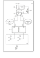
도 2에 도시된 바와 같이, 도시된 실시예에서 본 발명의 제1 측면에 따른 지향성 안테나 모듈(1)은 안테나 어레이(2)를 포함한다. 도 2에 도시된 실시예에 있어서, 안테나 어레이(2)는 두 개의 소자 어레이로 형성된다. 도 2에 도시된 바와 같이, 도시된 실시예에서 안테나 어레이(2)는 180도 하이브리드 회로(hybrid circuit; 4)에 연결되는 두 개의 안테나 소자들(3-1, 3-2)을 포함한다. 180도 하이브리드 회로(4)는 제1 출력(5-1) 및 제2 출력(5-2)을 포함한다. 180도 하이브리드 회로(4)는 두 개의 안테나 소자들(3-1, 3-2)로부터 수신되는 두 개의 안테나 신호들의 동상 합 신호(inphase summation signal) 및 이상 합 신호(out-of-phase summation signal)를 생성한다. 안테나 어레이(2)는 180도 하이브리드 회로(4)에 연결되는 선형의 두 소자 안테나 어레이를 형성한다. 하이브리드 회로(4)의 합 출력(sum output)(5-1)은 두 개의 안테나 소자들(3-1, 3-2)에 의해 수신되는 두 개의 안테나 신호들의 동상 합 신호를 전달한다. 또한, 도 1에 도시된 바와 같이, 이는 안테나 어레이의 브로드사이드(broadside) 방향에서 메인 빔(main beam)을 갖는 방사 패턴을 형성한다. 이와 달리, 도 3에 도시된 바와 같이, 하이브리드 회로(4)의 델타 출력(delta output)(5-2)은 브로드사이드 방향에서 널값(null value)을 생성하는 이상 합 신호를 전달한다. 180도 하이브리드 회로(4)의 합 출력(5-1)은 제1 신호선(signal line, 6-1)을 통해 스위칭 소자(8)의 제1 입력(7-1)에 연결된다. 도 2에 도시된 바와 같이, 하이브리드 회로(4)의 델타 출력(5-2)은 신호선(6-2)을 통해 스위칭 소자(8)의 제2 입력(7-2)에 연결된다. 도시된 실시예에 있어서, 스위칭 소자(8)는 두 개의 입력 단자들(7-1, 7,2), 출력 단자(7-3) 및 제어 입력(7-4)을 포함하는 RF 스위치로 구현된다. 도시된 예시적인 실시예에 있어서, RF 스위치(8)의 출력(7-3)은 신호선(9)을 통해 지향성 안테나 모듈(1)의 안테나 모듈 출력(11)에 연결되는 바이어스-T 커플러(bias-T coupler; 10)에 연결된다. 도 2에 도시된 실시예에 있어서, 지향성 안테나 모듈(1)의 스위칭 소자(8)는 방향 탐지 모드 제어 신호(Direction Finding Mode Control Signal; DFM-CRTL)에 응답하여 하이브리드 회로(4)의 합 출력(5-1)에서의 동상 합 신호 출력과 델타 출력(5-2)에서의 이상 합 신호 출력의 사이를 스위칭한다. 도 2의 실시예에 있어서, 방향 탐지 모드 제어 신호(DFM-CRTL)는 RF 스위칭 소자(8)와 바이어스-T 커플러 소자(10)를 연결하는 제어 신호선(12)을 통해 RF 스위칭 소자(8)의 제어 입력(7-4)으로 인가된다.As shown in Fig. 2, in the illustrated embodiment, the
지향성 안테나 모듈(1)의 안테나 모듈 출력(11)은 안테나 모듈 출력 단자(11)에서 지향성 안테나 모듈(1)에 의해 출력되는 지향성 안테나 모듈(1)의 안테나 출력 신호를 전처리 및/또는 처리하는 전자 회로들을 포함하는 안테나 핸들에 연결될 수 있다. 도 2에 도시된 실시예에 있어서, 방향 탐지 모드 제어 신호(DFM-CRTL)는 안테나 핸들로부터 지향성 안테나 모듈(1)의 안테나 모듈 출력(11)에서 수신되며 바이어스-T 커플링 소자(10)에 의해 커플 아웃(coupled-out)되어 RF 스위칭 소자(8)를 제어한다. 가능한 실시예에 있어서, RF 출력선(RF output line)의 내부 컨덕터(conductor)로 공급되는 바이어스 전압(VBIAS)은 RF 스위칭 소자(8)에 대한 스위칭 제어 신호로서 사용된다. 바이어스-T 커플링 소자(10)는 각 DC 전압들, 예를 들어, 3볼트의 제1 DC 전압과 5볼트의 제2 DC전압을 커플 아웃시킨다. RF 스위칭 소자(8)의 제어 입력(7-4)에 인가되는 DC 전압 레벨에 기초하여, 제1 입력(7-1) 또는 제2 입력(7-2)이 RF 스위칭 소자(8)의 출력(7-3)으로 스위칭된다. 이에 따라, 스위칭 소자(8)는 RF 스위칭 소자(8)의 제어 입력(7-4)에 인가되는 방향 탐지 모드 제어 신호(DFM-CRTL)에 대한 응답으로 동상 합 신호와 이상 합 신호의 사이를 스위칭한다. 스위칭되는 안테나 신호는 안테나 모듈 출력 단자(11)에서 지향성 안테나 모듈(1)에 의해 출력된다. 도 2에 도시된 실시예에 있어서, 방향 탐지 모드 제어 신호(DFM-CRTL)는 지향성 안테나 모듈(1)의 안테나 모듈 출력 단자(11)에서 배열되는 바이어스-T 소자(10)에 의해 커플 아웃(coupled out)된다. 다른 실시예에 있어서, 방향 탐지 모드 제어 신호(DFM-CRTL)는 또한 지향성 안테나 모듈(1)의 제어 버튼에 의해 제어될 수 있다. 상기 실시예에 있어서, 사용자는 제어 버튼을 조작하여 지향성 안테나 모듈(1)의 두 개의 상이한 방향 탐지 모드 사이를 스위칭할 수 있다.The
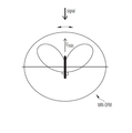
도 2에 도시된 바와 같이, 지향성 안테나 모듈(1)은 최대 방향 탐지 모드(MAX-DFM)와 최소 방향 탐지 모드(MIN-DFM)의 사이를 스위칭할 수 있다. 최대 방향 탐지 모드(MAX-DFM)에서, 180도 하이브리드 회로(4)에 의한 합 출력(5-1)에서의 동상 합 신호(∑) 출력은 스위칭 소자(8)에 의해 지향성 안테나 모듈(1)의 안테나 모듈 출력 단자(11)로 스위칭된다. 최소 방향 탐지 모드(MIN-DFM)에서, 180도 하이브리드 회로(4)의 델타 출력(5-2)에서의 이상 합 신호호의의 출력은 스위칭 소자(8)에 의해 지향성 안테나 모듈(1)의 안테나 모듈 출력 단자(11)로 스위칭된다. 이에 따라, 지향성 안테나 모듈(1)은 결합되는(combined) 최대 및 최소 로컬리제이션(localization)을 제공한다. 바람직한 실시예에 있어서, 안테나 방사 패턴의 최대 및 최소는 안테나의 스케닝(scanning)이 필요하지 않도록 동일한 각도 방향을 가리키게 된다. 도 2에 도시된 실시예에 있어서, 최대 패턴과 최소 패턴의 사이의 변화는 예를 들어, 지향성 안테나 모듈(1)에 연결되는 안테나 핸들 상의 버튼을 누름으로써 전자적으로 발생한다. 다른 실시예에 있어서, 제어 버튼은 또한 지향성 안테나 모듈(1)에서 직접 배치될 수 있다. 도 2에 도시된 바와 같이, 지향성 안테나 모듈(1)은 신호 방출기 또는 방사원(radiation source)과 근접한 방향 범위를 탐색하기 위해 최대 방향 탐지 모드(MAX-DFM)에서 먼저 동작한다. 이에 따라, 지향성 안테나 모듈(1)은 먼저, 안테나 어레이(2)의 안테나 소자들(3-1, 3-2)에 연결되는 180도 하이브리드 회로(4)에 의해 출력되는 동상 합 신호(∑)가 지향성 안테나 모듈(1)에 의해 안테나 핸들로 출력될 때 최대 방향 탐지 모드(MAX-DFM)로 스위칭된다. 안테나 핸들에 연결되는 지향성 안테나 모듈(1)은 지향성 안테나 모듈(1)에 의해 출력되는 동상 합 신호(∑)가 최대치에 도달할 때까지 사용자에 의해 피벗(pivot)된다. 신호원의 근접 방위가 이러한 방법으로 탐지되는 후, 지향성 안테나 모듈(1)은 사용자에 의해, 예를 들어, 안테나 핸들에서의 제어 버튼 또는 안테나 모듈(1)에서의 제어 버튼이 눌러짐으로써, 최소 방향 탐지 모드(MIN-DRM)로 스위칭되며, 상기 안테나 어레이(2)의 적어도 두 개의 안테나 소자(3-1, 3-2)에 연결되는 180도 하이브리드 회로(4)에 의해 출력되는 이상 합 신호(Δ)는 지향성 안테나 모듈(1)에 의해 안테나 핸들로 출력된다. 지향성 안테나 모듈(1)이 최소 방향 탐지 모드(MIN-DFM)로 스위칭되는 후, 사용자는 지향성 안테나 모듈(1)에 의해 출력되어 안테나 핸들로 향하는 이상 합 신호(Δ)가 신호원의 방위를 나타내는 최소치에 도달할 때까지 지향성 안테나 모듈(1)을 피벗시킬 수 있다. 상기 방위는 1도 미만의 정확도로 측정될 수 있다.As shown in Fig. 2, the
도 1은 최대 방향 탐지 모드(MAX-DFM)에서 지향성 안테나 모듈(1)에 의해 수행되는 최소 방향 탐지를 나타낸다. 사용자는 지향성 방사 패턴을 대략 포함하는 지향성 안테나 모듈(1)을 신호원에 의해 발생되는 간섭 신호의 예상 방향으로 지향시키며 신호가 최대치에 도달할 때까지 지향성 안테나 모듈(1)을 천천히 앞뒤로 피벗시킨다. 이후, 도 3에 도시된 바와 같이, 사용자는 지향성 안테나 모듈(1)을 최소 탐지 모드(MIN-DFM)로 스위칭한다. 도 3에 도시된 바와 같이, 최소 방향 탐지 모드(MIN-DFM)에서, 지향성 안테나 모듈(1)은 방사 패턴의 최소치가 신호원 또는 송신기의 방향을 나타내는 동안 동작 상태에 접어들게 된다. 최소 방향 탐지 모드(MIN-DFM)는 안테나가 안테나 최대 위치 근처에서 만드는 유사한 각도 변화들보다 현재 더 큰 변화들을 만드는 근처 널 위치(null position)에서의 효과를 활용한다. 결과적으로, 방사 패턴의 최소치를 이용하는 방향 탐지는 최대 방향 탐지를 수행하는 것보다 더 정확하다. 바람직한 실시예에 있어서, 안테나 방사 패턴은 모호함을 피하기 위해 오직 하나의 최대치를 보이게 된다. 가능한 실시예에 있어서, 최대치 대비 최소치의 비율은 적어도 20dB 일 수 있다. 본 발명의 제1 측면에 따른 안테나 모듈(1)에서는, 신호원의 방위의 측정이 두 개의 측정 단계로 순차적 수행된다. 먼저, 최대 방향 탐지 측정은 안테나 모듈(1)의 최대 방향 탐지 모드(MAX-DFM)에서 수행되고 다음으로 지향성 안테나 모듈(1)의 최소 방향 탐지 모드(MIN-DFM)에서 수행된다.Fig. 1 shows the minimum direction detection performed by the
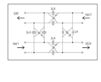
도 4는 본 발명의 제1 측면에 따른 지향성 안테나 모듈(1)의 가능한 실시예에서 사용될 수 있는 180도 하이브리드 회로(4)의 가능한 예시적인 실시예의 회로도를 나타낸다. 다른 실시예에 있어서, 다른 180도 하이브리드 회로(4) 또한 사용될 수 있다. 도 4에 도시된 실시예에 있어서, 180도 하이브리드 회로(4)는 집중 회로 소자들(lumped circuit elements)에 기초된다. 도 4에 도시된 바와 같이, 대칭 격자 구조가 배열된다. 바람직한 실시예에 있어서, 180도 하이브리드 회로(4)의 소자들은 인쇄 회로 기판(printed circuit board; PCB) 상에 인쇄될 수 있다.4 shows a circuit diagram of a possible exemplary embodiment of a 180 degree
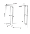
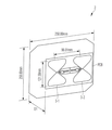
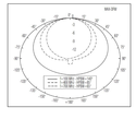
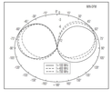
가능한 실시예에 있어서, 지향성 안테나 모듈(1)은 반사판(reflector plate)의 전방에 배치되는 부하 루프 안테나들(loaded loop antennas)에 의해 형성되며 제1 저주파수 범위에서 사용되는 안테나 소자들을 갖는 안테나 어레이(2)를 포함한다. 도 5는 반사판의 전방에서 거리(D1)에 배치되는 부하 루프 안테나들에 의해 각각 형성되는 적어도 두 개의 안테나 소자들(3-1, 3-2)을 포함하는 안테나 어레이(2)의 가능한 예시적인 실시예를 나타낸다. 도 5에 도시된 안테나 어레이(2)는 제1 저주파수 범위, 예를 들어, 100 MHz와 700 MHz 사이의 주파수 범위에서 사용될 수 있다. 도 7a 및 도 7b는 H-평면(H-plane) 내 제1 주파수 범위 즉, 100 MHz와 700 MHz의 사이에서 측정되는 방사 패턴들을 나타낸다. 도 7a는 최대 방향 탐지 모드(MAX-DFM)에서 측정되는 방사 패턴을 나타내며, 도 7b는 안테나 모듈(1)의 최소 방향 탐지 모드(MIN-DFM)에서 제1 주파수 범위에서 측정되는 방사 패턴을 나타낸다. 제1 주파수 대역에서, 기 설정되는 지향성을 갖는 안테나 소자들(3-1, 3-2)이 사용되어 고유한 메인 로브(unique main lobe)를 생성한다. 도 5에 도시된 바와 같이, 제1 주파수 범위에 사용되는 안테나 소자들(3-1, 3-2)은 반사판의 전방에 배치되는 부하 루프 안테나들이다. 도시된 실시예에 있어서, 반사판은 250 × 250 mm의 크기를 갖는 정사각형 반사판(reflector plate; RP)이다. 도시된 실시예에 있어서, 부하 루프 안테나 소자들(3-1, 3-2)은 반사판(RP)의 전방에서 거리(D1)에 위치한 직사각형 루프들이다. 가능한 실시예에 있어서, 거리(D1)는 고정된다. 다른 실시예에 있어서, 거리(D1)는 조정될 수 있다. 도 5에 도시된 바와 같이, 두 개의 루프 안테나 소자들(3-1, 3-2)은 거리(D2)만큼 이격되어 있다. 도시된 실시예에 있어서, 두 개의 부하 루프 안테나들(3-1, 3-2) 사이의 거리(D2)는 200 mm일 수 있다. 두 개의 부하 루프 안테나들(3-1, 3-2)은 작은 지향성을 나타낸다. 도시된 실시예에 있어서, 두 개의 안테나 소자들(3-1, 3-2) 사이의 거리(D2)는 저주파수용으로 전기적으로 작은 200 mm이다. 이러한 이유로, 최대 방향 탐지 모드(MAX-DFM)에서, 부하 루프 안테나들만으로는 어떠한 어레이 이득도 기대할 수 없다. 그러므로, 부하 루프 안테나들(3-1, 3-2)은 반사판(RP)의 전방에 배치되며, 각 주파수 대역에서 고주파수들 즉, 제1 주파수 범위에서만 동작한다. 최대 방향 탐지 모드(MAX-DFM)를 위해 H-평면에서 측정되는 방사 패턴들은 도 7a에 도시되며, 최소 방향 탐지 모드(MIN-DFM)를 위해 H-평면에서 측정되는 방사 패턴은 도 7b에 도시된다. 최대 방향 탐지 모드(MAX-DFM)에서의 반전력 빔 폭(Half Power Beam Width ; HPBW)은 140도와 65도의 사이에서 변하며, 도 7b에 도시된 최소 방향 탐지 모드(MIN-DFM)에서의 널값의 반전력 빔 폭(HPBW)은 최대치 25도 근방에서 대체로 일정하다. 실질적인 이득은 주파수 대역의 하단에서 -25 dBi로 시작하며 상부 에지에서 2 dBi로 증가한다. 도 7a 및 도 7b에 도시된 바와 같이, 지향성은 최소 방향 탐지 모드에서 5 dBi와 7 dBi 사이에서 변화한다. 도 5의 실시예에 있어서, 부하 루프 안테나들(3-1, 3-2)은 직사각형 형상을 가진다. 부하 루프 안테나들(3-1, 3-2)은 또한 상이한 형태들, 예를 들어 원형 또는 삼각형 형태를 가질 수 있다. In a possible embodiment, the
본 발명의 제1 측면에 따른 지향성 안테나 모듈(1)의 다른 가능한 실시예에 있어서, 안테나 어레이(2)는 반사판의 전방에 배치되며 제2 주파수 범위에서 사용되는 다이폴 안테나들(dipole antennas)에 의해 형성되는 안테나 소자들(3-1, 3-2)을 포함할 수 있다. 가능한 실시예에 있어서, 제2 주파수 범위는 700 MHz와 2.5 GHz 사이의 주파수 범위일 수 있다. 도 6은 700 MHz와 2.5GHz 사이의 제2 주파수 범위에서 사용되는 반사판(RP)의 전방에 배치되는 다이폴 안테나들에 의해 형성되는 안테나 소자들(3-1, 3-2)을 갖는 안테나 어레이(2)를 포함하는 지향성 안테나 모듈(1)의 안테나 어레이(2)의 가능한 예시적인 실시예를 나타낸다. 상기 주파수 범위는 일반적으로 GSM, UMTS 또는 LTE와 같은 이동 통신 네트워크에서 사용된다. 도 6의 구현예에 있어서, 도 6에 도시된 바와 같이 안테나 어레이(2)의 다이폴 안테나들(3-1, 3-2), 180도 하이브리드 회로(4) 및 스위칭 소자(8)는 공통 인쇄 회로 기판(PCB)에 인쇄될 수 있다. 인쇄 회로 기판(PCB)은 반사판(RP)의 전방에서 거리(D1)에 위치될 수 있다. 가능한 실시예에 있어서, 거리(D1)는 고정된다. 다른 실시예에 있어서, 인쇄 회로 기판(PCB)과 반사판(RP)의 사이의 거리(D1)는 조정될 수 있다. 도시된 실시예에 있어서, 인쇄 회로 기판(PCB)은 121.6 mm × 96 m의 크기를 갖는다. 반사판(RP)은 250 mm × 250 mm의 크기를 갖는 정사각형 반사판이다. 180도 하이브리드 회로(4)는 두 개의 다이폴 안테나들(3-1, 3-2) 사이의 인쇄 회로 기판의 중앙에 인쇄될 수 있다. 도시된 실시예에 있어서, 다이폴 안테나들(3-1, 3-2)은 모두 두 개의 원뿔 형상의 다이폴 반 영역들(half areas)에 의해 형성된다. 도 6에 도시된 바와 같이, 두 개의 다이폴 반 영역들의 사이에서, 작은 틈이 형성된다. 안테나 소자(3-i)의 다이폴 반 영역은 180도 하이브리드 회로(4)의 차동 입력에 연결된다. 가능한 실시예에 있어서, 인쇄 회로 기판(PBC)에 인쇄되는 두 개의 다이폴 안테나들(3-1, 3-2)에 연결되는 180도 하이브리드 회로(4)는 도 4에 도시된 바와 같이 구현된다. 출력 단자 즉, 180도 하이브리드 회로(4)의 단자(5-1, 5-2)는 안테나 어레이(2)의 인쇄 회로 기판(PCB)에 인쇄되거나 배치될 수 있는 RF 스위칭 소자(8)에 연결될 수 있다. 상기 RF 스위칭 소자(8)는 동축 케이블을 통해 지향성 안테나 모듈(1)의 출력 모듈 단자(11)에 직접 연결되거나 바이어스-T 커플링 소자(10)를 통해 안테나 모듈(1)의 출력 모듈 단자(11)에 연결될 수 있다.In another possible embodiment of the
도 5 및 도 6에 도시된 실시예에 있어서, 안테나 어레이들(2)의 반사판들(RP)은 바람직한 실시예로서 전기 전도성 물질로 제조된다.In the embodiment shown in Figures 5 and 6, the reflector plates RP of the
도 8a 및 도 8b는 H-평면에서 0.7 GHz와 2.5 GHz 사이의 제2 주파수 범위에서 도 6에 도시된 안테나 어레이(2)의 측정되는 방사 패턴들을 나타낸다. 도 8a는 최고 방향 탐지 모드(MAX-DFM)에서 측정되는 방사 패턴을 나타내며, 도 8b는 지향성 안테나 모듈(1)의 최소 방향 탐지 모드(MIN-DFM)에서 측정되는 방사 패턴을 나타낸다. 제2 고주파수 범위에서, 도 6에 도시된 두 개의 소자 다이폴 어레이(2)가 사용될 수 있다. 안테나 소자들(3-1, 3-2)은 반사판(RP)의 정면에서 100 mm의 거리에 배치될 수 있다. 반사판(RP)은 메인 로브를 앞으로 정렬시키는 데 사용될 수 있다.Figures 8A and 8B show measured radiation patterns of the
동작 모드들 모두를 위한 H-평면에서 측정되는 방사 패턴들이 도 8a 및 도 8b에 도시된다. 최고 방향 탐지 모드(MAX-DFM)에서의 반 전력 빔 폭(HPBW)은 85도와 35도의 사이에서 변화하며, 최소 방향 탐지 모드(MIN-DFM)에서 널값의 반 전력 빔 폭(HPBW)은 최대 20도 근방에서 대체로 일정하다. 가능한 실시예에 있어서, 전체 주파수 범위의 이득은 약 5 dBi이며 지향성은 최대 방향 탐지 모드에서 7 dBi와 10 dBi 사이에서 변화한다. 가능한 실시예에 있어서, 모든 기계 부품들 및 안테나 모듈(1)의 하우징(housing)을 포함하는 안테나 모듈(1)의 무게는 0.6 kg 이하이다.The radiation patterns measured in the H-plane for all of the operating modes are shown in Figures 8A and 8B. The half power beam width (HPBW) in the maximum direction detection mode (MAX-DFM) varies between 85 and 35 degrees and the half power beam width (HPBW) of the null value in the minimum direction detection mode (MIN-DFM) It is almost constant in the vicinity of the road. In a possible embodiment, the gain of the entire frequency range is about 5 dBi and the directivity changes between 7 dBi and 10 dBi in the maximum direction detection mode. In a possible embodiment, the weight of the
다른 가능한 실시예에 있어서, 지향성 안테나 모듈(1)은 2.5 GHz를 벗어나는 제3 주파수 범위에서 사용되는 LPDA 안테나들에 의해 형성되는 안테나 소자들을 갖는 안테나 어레이(2)를 포함한다. In another possible embodiment, the
지향성 안테나 모듈(1)은 사용자에 의해 휴대 가능한 안테나 핸들(13)에 장착된다. 안테나 핸들(13)은 지향성 안테나 모듈(1)이 안테나 핸들에 장착된 것을 인식하는 모듈 인식부(14)를 포함할 수 있다. 가능한 실시예에 있어서, 안테나 핸들(13)의 모듈 인식부(14)는 안테나 핸들(13)에 장착되는 지향성 안테나 모듈(1)의 적어도 하나의 안테나 어레이(2)에 구현되는 안테나 소자(3-1, 3-2)의 타입(type)을 인식한다. 다른 가능한 실시예에 있어서, 모듈 인식부(14)는 장착되는 지향성 안테나 모듈(1)의 적어도 하나의 안테나 어레이(2)에 의해 지원되는 적어도 하나의 주파수 범위를 또한 인식한다. 가능한 실시예에 있어서, 안테나 핸들(13)은 인식되는 지향성 안테나 모듈(1)이 안테나 핸들에 성공적으로 장착되었음을 사용자에게 디스플레이하는 사용자 인터페이스(user interface)를 포함할 수 있다. 다른 실시예에 있어서, 사용자 인터페이스는 장착되는 지향성 안테나 모듈(1)에 의해 지원되는 주파수 범위들 또한 디스플레이할 수 있다. 예를 들어, 사용자 인터페이스는 하나, 둘 또는 세 개의 주파수 범위들(Frequency Ranges; FR)이 각각 제1 주파수로부터 제2 주파수까지 범위를 갖는 지향성 안테나 모듈(1)에 의해 지원되는지 여부에 대하여 사용자에게 디스플레이할 수 있다.The
가능한 실시예에 있어서, 지향성 안테나 모듈(1)은 두 개의 안테나 어레이 즉, 제1 주파수 범위, 예를 들어, 100 MHz와 700 MHz 사이에서 사용되는 반사판(RP)의 정면에 배치되는 부하 루프 안테나들에 의해 형성되는 안테나 소자(3-i)를 포함하는 제1 안테나 어레이(2-1) 및 제2 주파수 범위, 예를 들어, 700 MHz와 2.5 GHz 사이에서 사용되는 반사판(RP)의 정면에 배치되는 다이폴 안테나들에 의해 형성되는 안테나 소자(3-1)를 포함하는 제2 안테나 어레이(2-2)를 포함한다.In a possible embodiment, the
다른 가능한 실시예에 있어서, 지향성 안테나 모듈(1)은 세 개의 상이한 안테나 어레이들을 포함할 수 있다. 상기 실시예에 있어서, 지향성 안테나 모듈(1)은 부하 루프 안테나들에 의해 형성되는 안테나 소자들(3-i)을 구비하는 제1 안테나 어레이(2-1), 다이폴 안테나들에 의해 형성되는 안테나 소자들(3-1)을 포함하는 제2 안테나 어레이(2-2) 및 LPDA 안테나들에 의해 형성되는 안테나 소자들(3-i)을 포함하는 제3 안테나 어레이(2-3)를 포함할 수 있다. 제3 안테나 어레이(2-3)는 제3 주파수 범위, 예를 들어, 2.5 GHz의 주파수를 넘어서 사용될 수 있다.In another possible embodiment, the
가능한 실시예에 있어서, 지향성 안테나 모듈(1)은 주파수 범위 선택 제어 신호(Frequency Range Selection Control Signal; FRS-CRTL)에 응답하여 상이한 주파수 범위들(FR) 사이에서 스위칭될 수 있다. 지향성 안테나 모듈(1)은 주파수 범위 선택 신호(FRS-CRTL)에 응답하여 제1 주파수, 제2 주파수 및/또는 제3 주파수 사이에서 스위칭될 수 있다. 가능한 실시예에 있어서, 주파수 범위 선택 신호는 안테나 핸들(13) 내 회로에 의해 전자적으로 발생하며 안테나 신호선을 통해 장착되는 지향성 안테나 모듈(1)로 인가될 수 있다. 인가되는 주파수 선택 신호는 디커플링(decoupling) 전자 소자에 의해 커플 아웃되어 지향성 안테나 모듈(1)에서 구현되는 상이한 안테나 어레이들(2) 중 하나를 선택할 수 있다. 바람직한 실시예에 있어서, 지향성 안테나 모듈(1)에서 구현되는 각 안테나 어레이(2)는 각 안테나 어레이(2)의 안테나 소자들(3-i)로부터 수신되는 안테나 신호들의 동상 합 신호(∑) 및 이상 합 신호(Δ)를 제공하는 관련된 180도 하이브리드 회로(4)에 연결된다. 지향성 안테나 모듈(1)의 180도 하이브리드 회로(4-i) 각각에 관련되는 스위칭 소자(8-i)는 지향성 안테나 모듈(1)의 주파수 다중화부(frequency multiplexing unit, 12)에 인가될 수 있는 각 안테나 어레이(2)의 출력 신호를 출력하는 방향 탐지 모드 제어 신호(DFM-CRTL)에 응답하여 각 180도 하이브리드 회로(4)에 의해 출력되는 동상 합 신호(∑)와 이상 합 신호(Δ)의 사이에서 스위칭하도록 연결될 수 있다.In a possible embodiment, the
도 9는 본 발명의 제1 측면에 따른 지향성 안테나 모듈(1)의 가능한 예시적인 실시예의 블록도를 나타낸다. 도시된 실시예에 있어서, 지향성 안테나 모듈(1)은 특정 주파수 범위들에서 각각 제공되는 다수의 안테나 어레이들(2-1, 2-2… 2-n)을 포함한다. 가능한 실시예에 있어서, 다른 주파수 범위들(FRs)은 서로 약간씩 겹쳐질 수 있다. 안테나 어레이들(2-i)의 수(N)는 어플리케이션에 따라 달라질 수 있다. 도 9에 도시된 지향성 안테나 모듈(1)의 안테나 어레이(2-i) 각각은 관련된 180도 하이브리드 회로(4-i)에 연결된다. 이에 따라, 도시된 실시예에 있어서, 180도 하이브리드 회로(4-i)의 개수는 구현되는 안테나 어레이들(2-i)의 개수에 대응된다. 각 180도 하이브리드 회로(4-i)에는 관련되는 스위칭 소자(8-i)가 연결된다. 도 9에 도시된 바와 같이, 관련되는 스위칭 소자(8-i)는 방향 탐지 모드 제어 신호(DFM-CRTL)에 응답하여 각 180도 하이브리드 회로(4-i)에 의해 출력되는 동상 합 신호(∑)와 이상 합 신호(Δ) 사이에서 스위칭한다. 각 안테나 어레이(2-i)의 선택되는 출력 신호는 스위칭 소자(8-i)에 의해 도 9에 도시된 주파수 다중화부(12)에 인가된다. 도 9에 도시된 바와 같이, 주파수 다중화부(12)에 의해 지향성 안테나 모듈(1)의 출력 단자(11)로 출력되는 주파수 범위는 주파수 범위 선택 제어 신호(FRS-CRTL)에 응답하여 선택될 수 있다. 도 9에 도시된 바와 같이, 지향성 안테나 모듈(1)의 출력 단자(11)는 안테나 핸들(13)에 연결된다. 가능한 실시예에 있어서, 안테나 핸들(13)은 지향성 안테나 모듈(1)의 안테나 어레이들(2-i)에서 구현되는 안테나 소자들의 타입을 인식하는 모듈 인식부(14)를 포함할 수 있다. 모듈 인식부(14)는 장착되는 지향성 안테나 모듈(1)의 상이한 안테나 어레이들(2-i)에 의해 지원되는 적어도 하나의 주파수 범위(FR)를 또한 인식할 수 있다.Figure 9 shows a block diagram of a possible exemplary embodiment of a
도 9에 도시된 안테나 핸들(13)은 장치의 감도를 향상시키도록 활성화될 수 있는 저잡음 광대역 증폭기(low-noise wideband amplifier)를 포함할 수 있다. 수동 동작 모드에서, 저잡음 광대역 증폭기는 바이패스될 수 있으며 이에 따라 방향 탐지 장치가 강력한 신호원의 부근에서도 사용될 수 있다. 가능한 실시예에 있어서, 안테나 핸들(13)은 방위 결정을 위해 아날로그 나침반을 더 포함하거나, 통합되는 GPS 수신기 및 전자 나침반에 장착될 수 있다. 가능한 실시예에 있어서, 잠재적인 목표원(potential target source)은 휴대용 수신기와 함께 사용되는 경우 삼각 측량을 이용하여 지도상에 위치될 수 있다. 안테나 핸들(13)은 스마트 폰 또는 태블릿과 같은 모바일 디바이스에 대한 인터페이스를 더 포함할 수 있다. 도 9에 도시된 바와 같이, 핸들(13)은 지향성 안테나 모듈(1)의 상이한 동작 모드들을 선택을 위한 버튼들을 포함할 수 있다. 안테나 핸들(13)의 사용자 인터페이스에서 제공되는 선택 버튼들은 방향 탐지 모드(DFM)의 선택 및/또는 특정 주파수 범위(FR)의 선택을 위해 사용될 수 있다. 특정 실시예에 있어서, 안테나 핸들(13) 내 저잡음 증폭기는 수신기에 의해 전원과 함께 공급될 수 있다.The antenna handle 13 shown in FIG. 9 may include a low-noise wideband amplifier that can be activated to improve the sensitivity of the device. In the passive mode of operation, the low noise broadband amplifier can be bypassed so that the direction finding device can be used in the vicinity of a strong signal source. In a possible embodiment, the antenna handle 13 may further comprise an analog compass for orientation determination, or may be mounted to an integrated GPS receiver and electronic compass. In a possible embodiment, a potential target source may be placed on the map using triangulation when used with a portable receiver. The antenna handle 13 may further include an interface to a mobile device such as a smart phone or tablet. As shown in Fig. 9, the
도 10은 본 발명의 제2 측면에 따른 신호원의 방향 탐지를 위한 방법의 특정 예시적인 실시예의 흐름도를 나타낸다.10 shows a flow chart of a specific exemplary embodiment of a method for detecting the direction of a signal source according to the second aspect of the present invention.
제1 단계(S1)에서, 지향성 안테나 모듈(1)은 지향성 안테나 모듈(1) 내 안테나 어레이(2)의 적어도 두 개의 안테나 소자들에 연결되는 180도 하이브리드에 의해 출력되는 동상 합 신호(∑)가 지향성 안테나 모듈(1)에 의해 출력되는 동안 최대 방향 탐지 모드(MAX-DFM)로 스위칭된다.In a first step Sl the
제2 단계(S2)에서, 지향성 안테나 모듈(1)은 지향성 안테나 모듈(1)에 의해 출력되는 동상 합 신호(∑)가 최대치에 도달할 때까지 사용자에 의해 피벗된다.In the second step S2, the
이후, 제3 단계(S3)에서, 지향성 안테나 모듈(1)은 신호 최대치가 기록되는 경우 사용자에 의해 또는 자동으로 최소 방향 탐지 모드(MIN-DFM)로 스위칭된다. 최소 방향 탐지 모드(MIN-DFM)에서, 지향성 안테나 모듈(1) 내 안테나 어레이의 적어도 두 개의 안테나 소자들에 연결되는 180도 하이브리드에 의해 출력되는 이상 합 신호(Δ)는 지향성 안테나 모듈(1)에 의해 출력된다.Then, in the third step S3, the
마지막으로, 제4 단계(S4)에서, 지향성 안테나 모듈(1)은 지향성 안테나 모듈(1)에 의해 출력되는 이상 합 신호(Δ)가 목표 신호원의 방위를 나타내는 최소치에 도달할 때까지 사용자에 의해 피벗된다.Finally, in the fourth step S4, the
방위는 안테나 핸들의 사용자 인터페이스에 의해 사용자에게 출력될 수 있다. 다른 실시예에 있어서, 목표 신호원의 방위는 추가적인 처리를 위해 데이터 처리부로 공급될 수 있다. 지향성 안테나 모듈(1)은 고정확도(high accuracy) 및 고감도(high sensitivity)의 측정을 제공한다. 지향성 안테나 모듈(1)은 다중 경로 전파에 의해 야기되는 필드 왜곡들 및/또는 편광(polarization) 오차들에 영향을 받지 않는다. 지향성 안테나 모듈(1)은 상대적으로 높은 스캐닝 속도 및 높은 POI(Probability Of Intercept)를 제공한다. 가능한 실시예에 있어서, 지향성 안테나 모듈(1)은 도 9에 도시된 안테나 핸들(13)에 장착되는 휴대용 모듈일 수 있다. 지향성 안테나 모듈(1)은 자동차 또는 임의의 다른 이동 장치에 의해 휴대될 수 있다. 바람직한 실시예에 있어서, 안테나 모듈(1)의 회전 또는 피벗은 사용자에 의해 수행될 수 있다. 다른 가능한 실시예에 있어서, 지향성 안테나 모듈(1)의 피벗 또는 회전은 지향성 안테나 모듈(1)가 장착되는 회전 장치에 의해 자동으로 수행될 수 있다. 가능한 실시예에 있어서, 미세 조정(fine tuning)은 상이한 안테나 어레이(2)에서 사용되는 반사판 및 안테나 소자들(3-i)의 거리를 조절함으로써 수행될 수 있다. 다른 가능한 실시예에 있어서, 지향성 안테나 모듈(1)이 회전하는 회전 속도는 상이한 안테나 어레이(2)에서 구현되는 안테나 소자들에 따라 조정될 수 있다. 지향성 안테나 모듈(1)은 무선 모니터링(radio monitoring), 보안 서비스, 인텔리전스(intelligence), 통신 시스템 및 연구를 포함하는 광범위한 어플리케이션들에서 사용될 수 있다.The orientation can be output to the user by the user interface of the antenna handle. In another embodiment, the orientation of the target signal source may be supplied to the data processing unit for further processing. The
1 : 지향성 안테나 모듈
2 : 안테나 어레이
3-1, 3-2 : 안테나 소자
4 : 180도 하이브리드 회로
5-1 : 제1 출력
5-2 : 제2 출력
6-1 : 제1 신호선
6-2 : 제2 신호선
7-1 : 제1 입력
7-2 : 제2 출력
7-3 : 출력 단자
7-4 : 제어 입력
8 : 스위칭 소자
9 : 신호선
10 : 바이어스-T 커플러
11 ; 안테나 모듈 출력
12 : 제어 신호선
13 : 안테나 핸들
14 : 모듈 인식부1: directional antenna module
2: antenna array
3-1, 3-2: antenna element
4: 180 degree hybrid circuit
5-1: First output
5-2: Second output
6-1: First signal line
6-2: Second signal line
7-1: First input
7-2: Second output
7-3: Output terminal
7-4: Control input
8: Switching element
9: Signal line
10: Bias-T coupler
11; Antenna module output
12: control signal line
13: Antenna handle
14: Module recognition section
Claims (16)
적어도 두 개의 안테나 소자들(3)을 갖는 적어도 하나의 안테나 어레이(2)로서, 상기 안테나 소자들(3)은 상기 안테나 소자들(3)로부터 수신되는 안테나 신호의 동상 합 신호(∑) 및 이상 합 신호(Δ)를 제공하는 180도 하이브리드(4)에 연결되는, 적어도 하나의 상기 안테나 어레이(2); 및
방향 탐지 모드 제어 신호(Direction Finding Mode Control signal : DFM-CRTL)에 응답하여 상기 180도 하이브리드(4)에 의해 출력되는 상기 동상 합 신호(∑)와 상기 이상 합 신호(Δ)의 사이를 스위칭하여 상기 지향성 안테나 모듈(1)의 안테나 모듈 출력(11)에 안테나 출력 신호를 제공하는 스위칭 소자(8)를 포함하는, 지향성 안테나 모듈.
A directional antenna module (1) comprising:
At least one antenna array (2) having at least two antenna elements (3), said antenna elements (3) having a common-sum signal (?) Of an antenna signal received from said antenna elements (3) At least one antenna array (2) connected to a 180 degree hybrid (4) providing a sum signal (?); And
The inphase sum signal (?) Output by the 180 degree hybrid (4) in response to a direction finding mode control signal (DFM-CRTL) is switched between the abnormal sum signal (?) And a switching element (8) for providing an antenna output signal to an antenna module output (11) of the directional antenna module (1).
상기 지향성 안테나 모듈(1)은, 상기 180도 하이브리드에 의해 출력되는 상기 동상 합 신호(∑)가 상기 스위칭 소자(8)에 의해 상기 지향성 안테나 모듈(1)의 상기 안테나 모듈 출력(11)으로 스위칭되는 최대 방향 탐지 모드와, 상기 180도 하이브리드에 의해 출력되는 상기 이상 합 신호(Δ)가 상기 스위칭 소자(8)에 의해 상기 지향성 안테나 모듈(1)의 상기 안테나 모듈 출력(11)으로 스위칭되는 최소 방향 탐지 모드의 사이에서 스위칭 가능한, 지향성 안테나 모듈.
The method according to claim 1,
The directional antenna module 1 is configured such that the inphase sum signal Σ output by the 180 degree hybrid is switched by the switching device 8 to the antenna module output 11 of the directional antenna module 1, Of the directional antenna module (1) is switched to the antenna module output (11) of the directional antenna module (1) by the switching element (8) A directional antenna module switchable between direction detection modes.
상기 안테나 어레이(2)는, 반사판(RP)의 정면에 배치되는 부하 루프 안테나들(loaded loop antennas)에 의해 형성되고 제1 주파수 범위에서 사용되는 안테나 소자들(3)을 포함하는, 지향성 안테나 모듈.
The method according to claim 1 or 2,
The antenna array 2 includes antenna elements 3 formed by loaded loop antennas disposed in front of a reflector RP and used in a first frequency range, .
상기 안테나 어레이(2)는, 반사판(RP)의 정면에 배치되는 다이폴 안테나들(dipole antennas)에 의해 형성되고 제2 주파수 범위에서 사용되는 안테나 소자들(3)을 포함하는, 지향성 안테나 모듈.
4. The method according to any one of claims 1 to 3,
The antenna array (2) comprises antenna elements (3) formed by dipole antennas disposed in front of a reflector (RP) and used in a second frequency range.
상기 다이폴 안테나들, 상기 180도 하이브리드(4) 및 상기 스위칭 소자(8)는, 인쇄 회로 기판(PCB)에 인쇄되는, 지향성 안테나 모듈.
The method of claim 4,
Wherein the dipole antennas, the 180 degree hybrid (4) and the switching element (8) are printed on a printed circuit board (PCB).
상기 안테나 어레이(2)는, 제3 주파수 범위에서 사용되는 LPDA 안테나들에 의해 형성되는 안테나 소자들(3)을 포함하는, 지향성 안테나 모듈.
6. The method according to any one of claims 1 to 5,
Wherein the antenna array (2) comprises antenna elements (3) formed by LPDA antennas used in a third frequency range.
상기 스위칭 소자(8)는, 상기 지향성 안테나 모듈(1)의 상기 안테나 모듈 출력(11)에 배치되는 바이어스-T 소자에 의해 커플 아웃(coupled out)되는 방향 탐지 모드 제어 신호에 의해 제어되거나 또는 상기 지향성 안테나 모듈(1)의 제어 버튼에 의해 제어되는 RF 스위치인, 지향성 안테나 모듈.
7. The method according to any one of claims 1 to 6,
The switching element 8 is controlled by a direction detection mode control signal coupled out by a bias-T element disposed in the antenna module output 11 of the directional antenna module 1, A directional antenna module, which is an RF switch controlled by a control button of a directional antenna module (1).
상기 안테나 모듈(1)은, 상기 지향성 안테나 모듈(1)의 상기 스위칭 소자(8)로 공급되는 상기 지향성 방향 탐지 모드 제어 신호(DFM-CTRL)에 커플 인(couple in)되는 바이어스-T 소자를 포함하는 안테나 핸들(13)에 장착 가능한, 지향성 안테나 모듈.
The method according to any one of claims 1 to 7,
The antenna module 1 includes a bias-T element coupled to the directional direction detection mode control signal DFM-CTRL supplied to the switching element 8 of the directional antenna module 1 And is mountable to an antenna handle (13) comprising an antenna module (10).
상기 안테나 핸들(13)은, 상기 지향성 안테나 모듈(1)이 상기 안테나 핸들(13)에 장착된 것을 인식하는 모듈 인식부(14)를 포함하는, 지향성 안테나 모듈.
The method of claim 8,
Wherein the antenna handle (13) comprises a module recognition part (14) which recognizes that the directional antenna module (1) is mounted on the antenna handle (13).
상기 안테나 핸들(8)의 상기 모듈 인식부(14)는, 상기 안테나 핸들(13)에 장착되는 상기 지향성 안테나 모듈(1)의 상기 적어도 하나의 안테나 어레이(2)에 구현되는 안테나 소자들의 타입 및/또는 장착되는 상기 지향성 안테나 모듈(1)의 상기 적어도 하나의 안테나 어레이(2)에서 지원되는 적어도 하나의 주파수 범위를 인식하는, 지향성 안테나 모듈.
The method of claim 9,
The module recognition portion 14 of the antenna handle 8 is configured to detect the type of antenna elements implemented in the at least one antenna array 2 of the directional antenna module 1 mounted on the antenna handle 13, Recognizes at least one frequency range supported by the at least one antenna array (2) of the directional antenna module (1) being mounted.
상기 지향성 안테나 모듈(1)은,
100 MHz와 700 MHz 사이인 제1 주파수 범위에서 사용되는 반사판의 정면에 배치되는 부하 루프 안테나들에 의해 형성되는 안테나 소자들을 포함하는 제1 안테나 어레이(2-1); 및/또는
700 MHz와 2.5 GHz 사이인 제2 주파수 범위에서 사용되는 반사판의 정면에 배치되는 다이폴 안테나들에 의해 형성되는 안테나 소자들을 포함하는 제2 안테나 어레이(2-2); 및/또는
2.5 GHz를 초과하는 제3 주파수 범위에서 사용되는 LPDA 안테나들에 의해 형성되는 안테나 소자들을 포함하는 제3 안테나 어레이(2-3)를 포함하는, 지향성 안테나 모듈.
The method according to any one of claims 1 to 10,
The directional antenna module (1)
A first antenna array (2-1) comprising antenna elements formed by load loop antennas arranged in front of a reflector used in a first frequency range between 100 MHz and 700 MHz; And / or
A second antenna array (2-2) comprising antenna elements formed by dipole antennas disposed in front of a reflector used in a second frequency range between 700 MHz and 2.5 GHz; And / or
And a third antenna array (2-3) comprising antenna elements formed by LPDA antennas used in a third frequency range exceeding 2.5 GHz.
상기 지향성 안테나 모듈(1)은, 주파수 범위 선택 제어 신호(FRS-CRTL)에 응답하여 상이한 주파수 범위들의 사이에서 스위칭 가능한, 지향성 안테나 모듈.
The method according to any one of claims 1 to 11,
The directional antenna module (1) is switchable between different frequency ranges in response to a frequency range selection control signal (FRS-CRTL).
상기 지향성 안테나 모듈(1)의 안테나 어레이(2-i) 각각은, 상기 각 안테나 어레이(2-i)의 안테나 소자들(3)으로부터 수신되는 상기 안테나 신호들의 동상 합 신호(∑) 및 이상 합 신호(Δ)를 제공하는 관련되는 180도 하이브리드(4-i)에 연결되는, 지향성 안테나 모듈.
12. The method according to claim 11 or 12,
Each of the antenna arrays 2-i of the directional antenna module 1 receives an in-phase sum signal? Of the antenna signals received from the antenna elements 3 of each antenna array 2-i, Is connected to an associated 180 degree hybrid (4-i) providing a signal (?).
각 180도 하이브리드(4-i)에 연결되는 관련되는 스위칭 소자(8-i)는, 방향 탐지 모드 제어 신호(DFM-CRTL)에 응답하여 상기 각 180도 하이브리드(4-i)에 의해 출력되는 상기 동상 합 신호(∑)와 상기 이상 합 신호(Δ)의 사이에서 스위칭하도록 연결되어 상기 지향성 안테나 모듈(1)의 주파수 다중화부(12)에 인가되는 각 안테나 어레이(2-i)의 출력 신호를 출력하는, 지향성 안테나 모듈.
14. The method of claim 13,
The associated switching element 8-i connected to each of the 180 degree hybrids 4-i is output by each of the 180 degree hybrids 4-i in response to the direction detection mode control signal DFM-CRTL And an output signal of each of the antenna arrays 2-i applied to the frequency multiplexing section 12 of the directional antenna module 1 so as to switch between the in-phase sum signal? And the abnormal sum signal? And outputting the directional antenna module.
A method according to any one of claims 11 to 14, wherein the distance between the load loop antennas and the reflector (RP) of the antenna elements implemented in the first antenna array (2-1) of the directional antenna module (1) And / or the distance between the dipole antenna and the reflector (RP) of the antenna elements implemented in the second antenna array (2-2) of the directional antenna module (1) is adjustable.
지향성 안테나 모듈(1)을, 상기 지향성 안테나 모듈(1) 내 안테나 어레이의 적어도 두 개의 안테나 소자들에 연결되는 180도 하이브리드에 의해 출력되는 동상 합 신호(∑)가 상기 지향성 안테나 모듈(1)에 의해 출력되는 최대 방향 탐지 모드로 스위칭하는 단계(S1);
상기 지향성 안테나 모듈(1)을, 상기 지향성 안테나 모듈(1)에 의해 출력되는 상기 동상 합 신호가 최대치에 도달할 때까지 피벗하는 단계(S2);
상기 지향성 안테나 모듈(1)을, 상기 지향성 안테나 모듈(1) 내 상기 안테나 어레이(2)의 적어도 두 개의 안테나 소자들에 연결되는 상기 180도 하이브리드에 의해 출력되는 이상 합 신호(Δ)가 상기 안테나 모듈(1)에 의해 출력되는 최소 방향 탐지 모드로 스위칭하는 단계(S3); 및
상기 지향성 안테나 모듈(1)을, 상기 지향성 안테나 모듈(1)에 의해 출력되는 상기 이상 합 신호가 신호원의 방위를 나타내는 최소치에 도달할 때까지 피벗하는 단계(S4)를 포함하는, 신호원의 방향 탐지 방법.
A method of detecting a direction of a signal source,
Directional antenna module 1 is connected to at least two antenna elements of the antenna array in the directional antenna module 1 so that the inphase sum signal Σ output by the 180 degree hybrid is fed to the directional antenna module 1 (S1) switching to a maximum direction detection mode output by the controller;
Pivoting the directional antenna module (1) until the in-phase sum signal output by the directional antenna module (1) reaches a maximum value (S2);
Wherein the directional antenna module 1 is connected to at least two antenna elements of the antenna array 2 in the directional antenna module 1 such that the anomaly signal Δ outputted by the 180- Switching to a minimum direction detection mode output by the module (1) (S3); And
And pivoting (S4) the directional antenna module (1) until the abnormal sum signal output by the directional antenna module (1) reaches a minimum value representing the orientation of the signal source Direction detection method.
Applications Claiming Priority (2)
| Application Number | Priority Date | Filing Date | Title |
|---|---|---|---|
| EP16166220.0 | 2016-04-20 | ||
| EP16166220.0A EP3236278B1 (en) | 2016-04-20 | 2016-04-20 | Directional antenna module |
Publications (2)
| Publication Number | Publication Date |
|---|---|
| KR20170120032A true KR20170120032A (en) | 2017-10-30 |
| KR102289873B1 KR102289873B1 (en) | 2021-08-13 |
Family
ID=55794910
Family Applications (1)
| Application Number | Title | Priority Date | Filing Date |
|---|---|---|---|
| KR1020170049185A KR102289873B1 (en) | 2016-04-20 | 2017-04-17 | Directional antenna module |
Country Status (5)
| Country | Link |
|---|---|
| US (1) | US10790584B2 (en) |
| EP (1) | EP3236278B1 (en) |
| KR (1) | KR102289873B1 (en) |
| CN (1) | CN107305245B (en) |
| ES (1) | ES2842198T3 (en) |
Families Citing this family (3)
| Publication number | Priority date | Publication date | Assignee | Title |
|---|---|---|---|---|
| CN107959126B (en) * | 2017-12-13 | 2024-02-27 | 华诺星空技术股份有限公司 | Antenna device for passive detection and positioning of anti-unmanned aerial vehicle |
| CN109633722B (en) * | 2019-01-11 | 2023-01-24 | 中国民航大学 | Small unmanned aerial vehicle satellite north-seeking method based on one-third L1 wavelength antenna configuration |
| CN110797660B (en) * | 2019-11-14 | 2021-07-13 | 中信科移动通信技术股份有限公司 | Direction finding antenna and direction finding method |
Citations (8)
| Publication number | Priority date | Publication date | Assignee | Title |
|---|---|---|---|---|
| US4240080A (en) * | 1979-11-19 | 1980-12-16 | The United States Of America As Represented By The Secretary Of The Army | Short backfire antenna with sum and error patterns |
| US4319249A (en) * | 1980-01-30 | 1982-03-09 | Westinghouse Electric Corp. | Method and antenna for improved sidelobe performance in dipole arrays |
| KR20010014070A (en) * | 1998-04-22 | 2001-02-26 | 요트.게.아. 롤페즈 | Antenna diversity system |
| US20070139285A1 (en) * | 2004-09-22 | 2007-06-21 | Matsushita Electric Industrial Co., Ltd. | Loop antenna unit and radio communication medium processor |
| WO2009050488A2 (en) * | 2007-10-19 | 2009-04-23 | Technology Solutions (Uk) Limited | Readers |
| JP2010223649A (en) * | 2009-03-23 | 2010-10-07 | Furukawa Electric Co Ltd:The | Radar device |
| CN203423253U (en) * | 2013-08-27 | 2014-02-05 | 中船重工鹏力(南京)大气海洋信息系统有限公司 | Portable high-frequency ground wave radar receiving antenna |
| KR20160029616A (en) * | 2014-09-05 | 2016-03-15 | 한국전자통신연구원 | Apparatus and Method for Finding Hybrid Direction using Two Baseline |
Family Cites Families (18)
| Publication number | Priority date | Publication date | Assignee | Title |
|---|---|---|---|---|
| US4360816A (en) * | 1971-07-21 | 1982-11-23 | The United States Of America As Represented By The Secretary Of The Navy | Phased array of six log-periodic dipoles |
| GB1472893A (en) * | 1974-01-30 | 1977-05-11 | Rudge A | Directional antenna systems |
| US4315266A (en) * | 1980-07-25 | 1982-02-09 | Nasa | Spiral slotted phased antenna array |
| DE9002945U1 (en) * | 1990-03-15 | 1990-09-13 | Weiner, Karl, Dipl.-Verwaltungswirt, 8670 Hof, De | |
| DE10012080C1 (en) * | 2000-03-14 | 2001-10-31 | Daimler Chrysler Ag | Antenna array and method for operating an antenna array |
| US6933907B2 (en) * | 2003-04-02 | 2005-08-23 | Dx Antenna Company, Limited | Variable directivity antenna and variable directivity antenna system using such antennas |
| US7505435B2 (en) * | 2003-12-02 | 2009-03-17 | Intel Corporation | RF circuitry and compact hybrid for wireless communication devices |
| KR200371277Y1 (en) * | 2004-05-18 | 2004-12-29 | (주)더블유엘호스트 | The RF Repeater System Using Single Beam Antenna. |
| JP4509870B2 (en) * | 2005-06-09 | 2010-07-21 | Dxアンテナ株式会社 | Antenna device |
| CN101436714B (en) * | 2007-11-15 | 2012-07-11 | 大同大学 | Part reflecting face antenna |
| US20090160638A1 (en) * | 2007-12-20 | 2009-06-25 | 3M Innovative Properties Company | Radio frequency identification reader system |
| KR101691246B1 (en) * | 2009-06-08 | 2016-12-29 | 인텔 코포레이션 | Multi-element amplitude and phase compensated antenna array with adaptive pre-distortion for wireless network |
| US9342716B2 (en) * | 2010-02-04 | 2016-05-17 | Carefusion 303, Inc. | Software-defined multi-mode RFID read devices |
| CN201804103U (en) * | 2010-10-12 | 2011-04-20 | 成都点阵科技有限公司 | Portable and integrated direction-finding mainframe with radio monitoring |
| KR20130095128A (en) * | 2012-02-17 | 2013-08-27 | 한국전자통신연구원 | Reader antenna and rfid electric shelf including the same |
| US20140049443A1 (en) * | 2012-08-15 | 2014-02-20 | Daniel A. Katz | Extendable Loop Antenna for Portable Communication Device |
| CN104239834A (en) * | 2013-06-24 | 2014-12-24 | 万信科技系统有限公司 | Radio frequency identification reader system and control method thereof |
| US10289877B2 (en) * | 2013-09-23 | 2019-05-14 | Hand Held Products, Inc. | Directional antenna for RFID tag finder |
-
2016
- 2016-04-20 ES ES16166220T patent/ES2842198T3/en active Active
- 2016-04-20 EP EP16166220.0A patent/EP3236278B1/en active Active
-
2017
- 2017-03-10 US US15/456,200 patent/US10790584B2/en active Active
- 2017-04-17 KR KR1020170049185A patent/KR102289873B1/en active IP Right Grant
- 2017-04-19 CN CN201710306468.7A patent/CN107305245B/en active Active
Patent Citations (8)
| Publication number | Priority date | Publication date | Assignee | Title |
|---|---|---|---|---|
| US4240080A (en) * | 1979-11-19 | 1980-12-16 | The United States Of America As Represented By The Secretary Of The Army | Short backfire antenna with sum and error patterns |
| US4319249A (en) * | 1980-01-30 | 1982-03-09 | Westinghouse Electric Corp. | Method and antenna for improved sidelobe performance in dipole arrays |
| KR20010014070A (en) * | 1998-04-22 | 2001-02-26 | 요트.게.아. 롤페즈 | Antenna diversity system |
| US20070139285A1 (en) * | 2004-09-22 | 2007-06-21 | Matsushita Electric Industrial Co., Ltd. | Loop antenna unit and radio communication medium processor |
| WO2009050488A2 (en) * | 2007-10-19 | 2009-04-23 | Technology Solutions (Uk) Limited | Readers |
| JP2010223649A (en) * | 2009-03-23 | 2010-10-07 | Furukawa Electric Co Ltd:The | Radar device |
| CN203423253U (en) * | 2013-08-27 | 2014-02-05 | 中船重工鹏力(南京)大气海洋信息系统有限公司 | Portable high-frequency ground wave radar receiving antenna |
| KR20160029616A (en) * | 2014-09-05 | 2016-03-15 | 한국전자통신연구원 | Apparatus and Method for Finding Hybrid Direction using Two Baseline |
Also Published As
| Publication number | Publication date |
|---|---|
| CN107305245A (en) | 2017-10-31 |
| US10790584B2 (en) | 2020-09-29 |
| ES2842198T3 (en) | 2021-07-13 |
| US20170310003A1 (en) | 2017-10-26 |
| CN107305245B (en) | 2023-12-22 |
| KR102289873B1 (en) | 2021-08-13 |
| EP3236278B1 (en) | 2020-12-09 |
| EP3236278A1 (en) | 2017-10-25 |
Similar Documents
| Publication | Publication Date | Title |
|---|---|---|
| Zhong et al. | A compact dual-band circularly polarized antenna with wide axial-ratio beamwidth for vehicle GPS satellite navigation application | |
| US7577464B2 (en) | Compact antenna system for polarization sensitive null steering and direction-finding | |
| Gómez-Tornero et al. | Hybrid analog-digital processing system for amplitude-monopulse RSSI-based MIMO WiFi direction-of-arrival estimation | |
| CN101675345B (en) | Radiation efficiency measuring device and radiation efficiency measuring method | |
| US7924225B2 (en) | Direction finding antenna systems and methods for use thereof | |
| US10416268B2 (en) | Multipolarized vector sensor array antenna system for search and rescue applications | |
| KR102289873B1 (en) | Directional antenna module | |
| US20160181690A1 (en) | Pentaband antenna | |
| Ghaemi et al. | A small-aperture, ultrawideband HF/VHF direction-finding system for unmanned aerial vehicles | |
| KR102080305B1 (en) | Integral laminated patch array antenna | |
| Yinusa et al. | Robust satellite navigation by means of a spherical cap conformal antenna array | |
| CN112103626B (en) | tapered wall cover | |
| Hua et al. | Direction-of-arrival estimator using array switching on software defined radio platform | |
| Muqaibel et al. | Sparse DOA estimation for directional antenna arrays: An experimental validation | |
| WO2020041858A1 (en) | Antenna array for radio direction finding and radio locating unit utilizing same | |
| WO2010006484A1 (en) | Direction finding antenna systems and methods for use thereof | |
| Toprak et al. | A compact wideband circular polarized antenna for automotive gnss applications | |
| KR100822705B1 (en) | Antenna for the direction finding of the phase comparison method | |
| CN113109757A (en) | Direction finding microwave channel assembly based on interferometer | |
| Ma et al. | Broadband, small-aperture direction-finding array with azimuth and elevation estimation capability | |
| Alsliety et al. | A study of ground-plane-level and vehicle-level radiation patterns of GPS antenna in telematics applications | |
| Zhang et al. | Recognition method studies for radar and communication signals based on spectral correlation | |
| CN215449570U (en) | Direction finding microwave channel assembly based on interferometer | |
| Baharuddin et al. | An Electronically Steerable Antenna Designed for Accurate DoA Determination of U-NII-2-Extended WLAN Devices | |
| US20220247510A1 (en) | Compact receiver system with antijam and antispoof capability |
Legal Events
| Date | Code | Title | Description |
|---|---|---|---|
| E902 | Notification of reason for refusal | ||
| E701 | Decision to grant or registration of patent right | ||
| GRNT | Written decision to grant |