JP2010223649A - Radar device - Google Patents
Radar device Download PDFInfo
- Publication number
- JP2010223649A JP2010223649A JP2009069378A JP2009069378A JP2010223649A JP 2010223649 A JP2010223649 A JP 2010223649A JP 2009069378 A JP2009069378 A JP 2009069378A JP 2009069378 A JP2009069378 A JP 2009069378A JP 2010223649 A JP2010223649 A JP 2010223649A
- Authority
- JP
- Japan
- Prior art keywords
- signal
- input
- sum
- radar apparatus
- switch
- Prior art date
- Legal status (The legal status is an assumption and is not a legal conclusion. Google has not performed a legal analysis and makes no representation as to the accuracy of the status listed.)
- Pending
Links
Images
Landscapes
- Radar Systems Or Details Thereof (AREA)
Abstract
Description
本発明は、ターゲットを検知してその方位を位相モノパルス方式により検出するレーダ装置に関するものである。 The present invention relates to a radar apparatus that detects a target and detects its direction by a phase monopulse method.
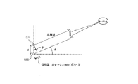
従来より、寸法が限定されたレーダ装置では、ターゲットの方位(角度)を検知するために位相モノパルス方式を用いるのが一般的である。図2に示すように、一つのターゲットで反射された反射波を2つの受信アンテナで受信すると、両者の間にはターゲットの方位によって形成される位相差が生じるが、位相モノパルス方式では、この位相差を用いてターゲットの方位を測定する。 Conventionally, in a radar apparatus with limited dimensions, it is common to use a phase monopulse method to detect the azimuth (angle) of a target. As shown in FIG. 2, when a reflected wave reflected by one target is received by two receiving antennas, a phase difference formed by the orientation of the target is generated between the two receiving antennas. The orientation of the target is measured using the phase difference.
位相モノパルス方式を用いて測角を行う従来のレーダ装置の構成例を図6に示す。送信パルス生成部901で生成されたパルス信号が、送信部902で所定の周波数にアップコンバートされて送信アンテナ903に出力され、送信アンテナ903から送信波が空中に放射される。放射された送信波は、ターゲットで反射されて2つの受信アンテナ904、905で受信される。受信アンテナ904、905で受信された受信信号は、それぞれ受信部906、907に入力されてダウンコンバートされ、それぞれの受信部906、907から直交位相変換されたI信号とQ信号が演算部908に出力される。演算部908には、距離演算部909、相対速度演算部910、及び方位演算部911が設けられており、それぞれでターゲットまでの距離、相対速度、及び方位が算出される。
A configuration example of a conventional radar apparatus that performs angle measurement using the phase monopulse method is shown in FIG. The pulse signal generated by the transmission
特許文献1には、複数本の受信アンテナと、それと同数の受信部を備える位相モノパルス式レーダについての記載がある。特許文献1に記載のレーダは、さらにカメラ装置を備える構成となっており、これを用いてターゲットが存在する方位角度領域を特定できるようにしている。これにより、位相の折り返しによるターゲットの方位を誤検出するのを防止している。
また特許文献2には、広帯域信号の到来方向を精度よく推定する方法についての記載がある。ここでは、2系統のアンテナを用い、それぞれのアンテナで受信した信号をハイブリッド回路に入力して和信号(Σ)と差信号(Δ)を作成している。ハイブリッド回路から出力される和信号(Σ)と差信号(Δ)を受信部に入力し、受信部からの出力を用いて広帯域信号の到来方向を推定している。信号の周波数帯域を分割し、分割された各帯域における|Δ/Σ|の落ち込む(極小である)方向が一致するとき、そのときの真正面方向(方位0°)が信号到来方向であると推定している。本方式も位相モノパルス方式の一つである。
位相モノパルス方式のレーダ装置では、反射波を受信するための受信アンテナが2系統以上設けられ、各受信アンテナで受信した受信信号を用いて位相モノパルス処理するために、少なくとも2系統の受信部を備えている。1系統あたりの受信部には、受信信号を増幅する増幅器、ダウンコンバートする装置、IQ復調方式によりI信号、Q信号を出力する装置、等が設けられている。そのため、このような受信系を複数備えるようにすると受信部の寸法が大きくなり、コストも高くなるといった問題があった。 In the phase monopulse radar device, two or more receiving antennas for receiving reflected waves are provided, and at least two receiving units are provided to perform phase monopulse processing using the received signals received by the receiving antennas. ing. The receiving unit for each system is provided with an amplifier that amplifies the received signal, a device for down-conversion, a device that outputs an I signal and a Q signal using an IQ demodulation method, and the like. For this reason, when a plurality of such receiving systems are provided, there is a problem that the size of the receiving unit increases and the cost also increases.
また、2系統以上の受信アンテナで受信された信号が異なる受信部で処理されて演算部に出力されているため、受信アンテナで受信されてから演算部に到達するまでに要する受信処理時間が受信部によって異なる場合には、演算部で正しく同期をとって処理することができなくなるおそれがある。そのため、どの受信部で処理されても受信処理時間がほぼ一致するように、受信部内の線路長等を高精度に管理する必要があり、これもコスト増加の要因となっている。 In addition, since signals received by two or more receiving antennas are processed by different receiving units and output to the calculation unit, the reception processing time required to reach the calculation unit after being received by the receiving antenna is received. If they differ from one part to another, there is a possibility that the arithmetic part cannot correctly perform synchronization. For this reason, it is necessary to manage the line length and the like in the receiving unit with high accuracy so that the reception processing times are almost the same regardless of which receiving unit is processed, which also causes an increase in cost.
本発明は、上記課題に鑑みてなされたものであり、受信部の構成をシンプルにして位相モノパルス方式により位相の測定を高精度に行えるレーダ装置を提供することを目的とする。 The present invention has been made in view of the above problems, and an object of the present invention is to provide a radar apparatus capable of measuring a phase with high accuracy by a phase monopulse method with a simple configuration of a receiving unit.
上記課題を解決するため、本発明のレーダ装置の第1の態様は、パルス信号を生成する送信パルス生成部と、前記送信パルス生成部から入力した前記パルス信号を所定の周波数帯にアップコンバートして高周波パルス信号を出力する送信部と、前記送信部から前記高周波パルス信号を入力して送信波を放射する1つの送信アンテナと、前記送信アンテナから放射された前記送信波がターゲットで反射されて戻ってきた反射波を受信して2つの受信信号を出力する2以上の受信アンテナと、前記2以上の受信アンテナから入力した前記2つの受信信号を加算した和信号及び前記2つの受信信号の一方から他方を減算した差信号を出力するハイブリッド回路と、前記ハイブリッド回路から前記和信号を入力する第1の入力端と、前記差信号を入力する第2の入力端と、所定の選択信号に従って前記第1の入力端または前記第2の入力端に接続されて前記和信号または前記差信号を出力する出力端とを有するスイッチと、前記スイッチから入力した前記和信号または差信号をIQ復調して相互に位相が直交するI信号及びQ信号を出力する受信部と、前記受信部から前記I信号及びQ信号を入力し、前記I信号及びQ信号のドップラーシフトによる周波数のずれから前記ターゲットの相対速度を算出するとともに、前記和信号と前記差信号との比を算出して前記ターゲットの方位を算出するする演算部と、を備えることを特徴とする。 In order to solve the above problems, a first aspect of the radar apparatus according to the present invention includes a transmission pulse generation unit that generates a pulse signal, and up-converts the pulse signal input from the transmission pulse generation unit into a predetermined frequency band. A transmission unit that outputs a high-frequency pulse signal, one transmission antenna that receives the high-frequency pulse signal from the transmission unit and radiates a transmission wave, and the transmission wave radiated from the transmission antenna is reflected by a target One of two or more receiving antennas that receive the reflected waves that have returned and output two received signals, a sum signal obtained by adding the two received signals input from the two or more receiving antennas, and the two received signals A hybrid circuit that outputs a difference signal obtained by subtracting the other from the first input terminal that inputs the sum signal from the hybrid circuit, and inputs the difference signal. A switch having a second input terminal and an output terminal connected to the first input terminal or the second input terminal and outputting the sum signal or the difference signal according to a predetermined selection signal; A receiver that IQ-demodulates the sum signal or difference signal input from, and outputs an I signal and a Q signal whose phases are orthogonal to each other; inputs the I signal and the Q signal from the receiver; A calculation unit that calculates a relative speed of the target from a frequency shift caused by a Doppler shift of a Q signal, and calculates a ratio between the sum signal and the difference signal to calculate a direction of the target. Features.
上記構成の本発明では、2以上の受信アンテナをスイッチを介して1系統の受信部に接続することで、受信部の構成をシンプルにして位相モノパルス方式により位相の測定を高精度に行うことが可能となる。 In the present invention having the above configuration, two or more receiving antennas can be connected to one receiving unit via a switch, thereby simplifying the configuration of the receiving unit and performing phase measurement with high accuracy by the phase monopulse method. It becomes possible.
本発明のレーダ装置の他の態様は、前記スイッチは、前記第1の入力端と前記第2の入力端とを交互に前記出力端に接続することで、前記和信号と前記差信号とを交互に出力することを特徴とする。和信号と差信号とを交互に受信部に出力して受信処理を行わせることで、和信号と差信号との間の時間的なずれを小さくすることができる。 According to another aspect of the radar apparatus of the present invention, the switch connects the first input terminal and the second input terminal to the output terminal alternately, so that the sum signal and the difference signal are connected. It outputs alternately. By alternately outputting the sum signal and the difference signal to the receiving unit to perform reception processing, a temporal shift between the sum signal and the difference signal can be reduced.
本発明のレーダ装置の他の態様は、前記スイッチは、前記第1の入力端と前記第2の入力端との切り替えを所定の時間間隔δtで周期的に行うことを特徴とする。スイッチの切り替えを一定周期で行わせることで、送信アンテナからの送信波の放射に同期させることが容易となる。 Another aspect of the radar apparatus of the present invention is characterized in that the switch periodically performs switching between the first input terminal and the second input terminal at a predetermined time interval δt. By performing switch switching at a constant period, it becomes easy to synchronize with the radiation of the transmission wave from the transmission antenna.
本発明のレーダ装置の他の態様は、前記送信パルス生成部から前記パルス信号を入力すると、前記スイッチに前記選択信号を出力するスイッチ制御部を備えることを特徴とする。これにより、スイッチの切り替えを送信パルス生成部からのパルス信号の出力に同期させて行わせることができる。 Another aspect of the radar apparatus of the present invention includes a switch control unit that outputs the selection signal to the switch when the pulse signal is input from the transmission pulse generation unit. Thereby, switching of the switch can be performed in synchronization with the output of the pulse signal from the transmission pulse generator.
本発明のレーダ装置の他の態様は、前記演算部は、前記受信部から入力した前記和信号または前記差信号のI信号及びQ信号と、前記受信部から前回入力した前記差信号または前記和信号のI信号及びQ信号に対し前記時間間隔δtの間に変化する変化量を補正した補正後のI信号及びQ信号と、を用いて前記方位を算出することを特徴とする。これにより、比の算出に用いる和信号と差信号とを同時刻のものにすることができる。 In another aspect of the radar apparatus of the present invention, the arithmetic unit is configured to input the sum signal or the difference signal I signal and the Q signal input from the receiver unit, and the difference signal or the sum signal input last time from the receiver unit. The azimuth is calculated using the corrected I signal and Q signal obtained by correcting the amount of change that changes during the time interval δt with respect to the I signal and Q signal of the signal. Thereby, the sum signal and difference signal used for calculation of the ratio can be made at the same time.
本発明のレーダ装置の他の態様は、前記補正後のI信号及びQ信号は、前記ドップラーシフトによる前記時間間隔δtの間の位相の変化を前回入力した前記差信号または前記和信号のI信号及びQ信号に対して補正して算出されることを特徴とする。ドップラーシフトによる位相の変化を用いて時間間隔δtの間の差信号または和信号の変化を補正することができる。 In another aspect of the radar apparatus of the present invention, the corrected I signal and Q signal are the difference signal or the sum signal I signal previously inputted with a phase change during the time interval δt due to the Doppler shift. And the Q signal is corrected and calculated. The change in the difference signal or the sum signal during the time interval δt can be corrected using the phase change due to the Doppler shift.
本発明のレーダ装置の他の態様は、前記演算部は、前記和信号と前記差信号との比の虚数部を算出して前記ターゲットの方位を算出することを特徴とする。受信アンテナの特性に応じて、和信号と差信号との比の虚数部を用いて方位を算出することができる。 In another aspect of the radar apparatus of the present invention, the calculation unit calculates an imaginary part of a ratio between the sum signal and the difference signal to calculate the azimuth of the target. Depending on the characteristics of the receiving antenna, the azimuth can be calculated using the imaginary part of the ratio between the sum signal and the difference signal.
本発明のレーダ装置の他の態様は、前記演算部は、前記和信号と前記差信号との比の実数部を算出して前記ターゲットの方位を算出することを特徴とする。受信アンテナの特性に応じて、和信号と差信号との比の実数部を用いて方位を算出することができる。 Another aspect of the radar apparatus of the present invention is characterized in that the calculation unit calculates a real part of a ratio between the sum signal and the difference signal to calculate the azimuth of the target. Depending on the characteristics of the receiving antenna, the azimuth can be calculated using the real part of the ratio of the sum signal and the difference signal.
本発明によれば、2以上の受信アンテナをスイッチを介して1系統の受信部に接続することで、受信部の構成をシンプルにして位相モノパルス方式により位相の測定を高精度に行えるレーダ装置を提供することが可能となる。 According to the present invention, there is provided a radar device capable of measuring a phase with high accuracy by a phase monopulse method by connecting two or more receiving antennas to a single receiving unit through a switch and simplifying the configuration of the receiving unit. It becomes possible to provide.
本発明の好ましい実施の形態におけるレーダ装置について、図面を参照して詳細に説明する。同一機能を有する各構成部については、図示及び説明簡略化のため、同一符号を付して示す。 A radar apparatus according to a preferred embodiment of the present invention will be described in detail with reference to the drawings. Each component having the same function is denoted by the same reference numeral for simplification of illustration and description.
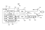
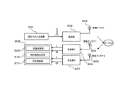
本発明の第1の実施形態に係るレーダ装置の構成を、図1を用いて説明する。図1は、本実施形態のレーダ装置100の構成を示すブロック図である。本実施形態のレーダ装置100は、送信系として、パルス信号を生成する送信パルス生成部101と、送信パルス生成部101から入力したパルス信号を所定の周波数帯にアップコンバートして高周波パルス信号を出力する送信部111と、送信部111から高周波パルス信号を入力して送信波を放射する送信アンテナ112と、を備えている。レーダ装置100の送信系として、例えば送信パルス生成部101からパルス幅1ns程度の広帯域ベースバンドのパルス信号を発出させ、これを送信部111で26.5GHz程度にアップコンバートして送信アンテナ112から放射させるように構成することができる。
The configuration of the radar apparatus according to the first embodiment of the present invention will be described with reference to FIG. FIG. 1 is a block diagram illustrating a configuration of a radar apparatus 100 according to the present embodiment. The radar apparatus 100 according to the present embodiment, as a transmission system, outputs a high-frequency pulse signal by up-converting a transmission
また受信系として、送信アンテナ112から放射された送信波がターゲットで反射されて戻ってきた反射波を受信する2つの受信アンテナ121、122と、受信アンテナ121、122から2つの受信信号を入力して両者を加算した和信号(Σ)と両者の差である差信号(Δ)を出力するハイブリッド回路123と、ハイブリッド回路123から和信号を入力する第1の入力端124aと、差信号を入力する第2の入力端124bと、和信号と差信号のいずれかを選択してを出力する出力端124cとを有するスイッチ124と、スイッチ124から入力した和信号または差信号をIQ復調して相互に位相が直交するI信号及びQ信号を出力する受信部125と、受信部125からI信号及びQ信号を入力してターゲットの相対速度及び方位を演算する演算部130と、を備えている。
In addition, as a receiving system, two
レーダ装置100は、位相モノパルス方式でターゲットの方位を測定できるように構成されている。すなわち、送信系が1系統で構成されて1つの送信アンテナ112を備えているのに対し、受信系は所定距離dだけ離れて配置された2つの受信アンテナ121、122を備えている。受信アンテナ121、122で受信されて出力される2つの受信信号は、ハイブリッド回路123に入力されて和信号と差信号の2つの信号に変換されて出力される。このように、本実施形態のレーダ装置100でも、2つの受信アンテナ121、122を用いて2つの受信信号(和信号、差信号)が出力されるように構成されている。しかし、線路長等の管理が複雑な受信部125については、これを1系統のみを備えるようにしている。これにより、レーダ装置100の小型化や低価格化が容易となる。
The radar apparatus 100 is configured to be able to measure the azimuth of the target using a phase monopulse method. That is, the transmission system is configured by one system and includes one
位相モノパルス方式で必要となる2つの受信信号に対し、これを1系統の受信部125で信号処理するために、レーダ装置100ではスイッチ124を備える構成としており、スイッチ124で2つの受信信号を交互に選択し、ここで選択された受信信号を受信部125に出力して信号処理させる構成としている。スイッチ124は、和信号と差信号の2つの受信信号を出力するハイブリッド回路123の出力側に接続されており、スイッチ124で和信号と差信号の2つの受信信号のいずれか1つを選択し、これを出力端124cに接続された受信部125に出力する構成としている。
The radar apparatus 100 is configured to include a
スイッチ124により和信号と差信号のいずれか一方を交互に選択させるために、スイッチ制御部102を設けてスイッチ124を制御させている。スイッチ制御部102は、送信パルス生成部101からパルス信号を入力し、これをトリガーとしてスイッチ124の入力端124a、124bを交互に切り替えて出力端124cに接続させている。送信パルス生成部101から出力されるパルス信号をトリガーとして、スイッチ124の切り替えを行わせることで、送信アンテナ112から放射された送信波に対して、その反射波を受信した受信信号を受信部125で確実に処理させることができる。
In order to alternately select one of the sum signal and the difference signal by the
受信部125から演算部130に出力されたI信号、Q信号を用いて、演算部130では、ターゲットの位置情報を算出する。レーダ装置100では、位相モノパルス方式を用いてターゲットの方位を測定するために、演算部130に方位演算手段131を備えている。また、ターゲットまでの距離を算出するための距離演算手段132、及びターゲットの相対速度を算出するための相対速度演算手段133を演算部130に備えるようにしており、ターゲットの位置情報としてターゲットまでの距離、ターゲットの存在する方位、及びターゲットの相対速度を提供することができる。
Using the I signal and the Q signal output from the
本実施形態のレーダ装置100では、方位演算手段131、距離演算手段132、及び相対速度演算手段133を有する演算部130は、デジタル演算装置である演算・制御部140に設けられている。また、送信部111とスイッチ制御部102にパルス信号を送出する送信パルス生成部101、及びスイッチ124を制御しているスイッチ制御部102も、ともに演算・制御部140に設けられている。
In the radar apparatus 100 of the present embodiment, the
本実施形態のレーダ装置100では、受信信号の和信号と差信号をスイッチ124で切り替えて受信部125で交互に処理する構成としていることから、演算部130に入力される和信号のI信号、Q信号と、差信号のI信号、Q信号との間にタイムラグδtが存在する。このタイムラグδtは、スイッチ124の切り替え周期、すなわち送信パルス生成部101からパルス信号が出力される周期に等しい。レーダ装置100及びターゲットが静止している場合には、このようなタイムラグがあってもターゲットの位置情報は変化せず問題はない。
In the radar apparatus 100 according to the present embodiment, the sum signal and the difference signal of the received signals are switched by the
しかし、レーダ装置100とターゲットの少なくとも一方が移動している場合には、このタイムラグδtの間にターゲットまでの距離や方位が変化してしまう。ターゲットまでの距離については、和信号と差信号のうちいずれか一方の最新の信号だけを用いて算出することができる。これに対し、方位の算出には和信号と差信号の両方を用いる必要があることから、上記のタイムラグδt及び相対速度の大きさによっては、方位の測定精度が低下するおそれがある。 However, when at least one of the radar device 100 and the target is moving, the distance and direction to the target change during this time lag δt. The distance to the target can be calculated using only the latest signal of either the sum signal or the difference signal. On the other hand, since it is necessary to use both the sum signal and the difference signal for the calculation of the azimuth, the measurement accuracy of the azimuth may be lowered depending on the time lag δt and the magnitude of the relative speed.
そこで、本実施形態のレーダ装置100では、上記のようなタイムラグδtによる和信号と差信号との間のずれを補正してターゲットの方位を算出するようにしており、これによりタイムラグδtや相対速度がある程度大きい場合でも、ターゲットの方位を高精度に算出できるようにしている。レーダ装置100とターゲットの少なくとも一方が移動している場合には、受信信号にドップラー効果による周波数シフトが生じている。演算部130の相対速度演算手段133では、受信部125から入力したI信号、Q信号をFFT(Fast Fourier Transform)処理してドップラー効果による周波数のずれfdを演算しており、これから相対速度を算出している。方位演算手段131では、相対速度演算手段133で算出された周波数のずれfdを用いてターゲットの方位を補正している。本実施形態のレーダ装置100では、タイムラグδtを10ms程度することができる。また、ドップラー効果による周波数のずれfdは、±6kHz以内の低い周波数(長い周期)となる。
Therefore, in the radar apparatus 100 according to the present embodiment, the azimuth of the target is calculated by correcting the deviation between the sum signal and the difference signal due to the time lag δt as described above, whereby the time lag δt and the relative speed are calculated. Even if is somewhat large, the orientation of the target can be calculated with high accuracy. When at least one of the radar apparatus 100 and the target is moving, a frequency shift due to the Doppler effect occurs in the received signal. The relative speed calculation means 133 of the
以下では、本実施形態のレーダ装置100で行う方位算出のための補正方法について説明する。ここでは、時刻T−δtに測定された和信号と、δt後の時刻Tに測定された差信号を用いてターゲットの方位を算出するものとする。この場合、和信号に対してタイムラグδtの間の変化を推定して補正する必要がある。なお、時刻T−δtに測定した差信号とδt後の時刻Tに測定した和信号を用いて方位を算出するようにしてもよく、その場合には差信号に対してタイムラグδtの間の変化を推定して補正する。これにより、同一時刻における和信号と差信号を用いてターゲットの方位を算出することが可能となる。 Hereinafter, a correction method for azimuth calculation performed by the radar apparatus 100 of the present embodiment will be described. Here, it is assumed that the azimuth of the target is calculated using the sum signal measured at time T−δt and the difference signal measured at time T after δt. In this case, it is necessary to correct the sum signal by estimating and changing the time lag δt. The azimuth may be calculated using the difference signal measured at time T−δt and the sum signal measured at time T after δt, and in that case, the change between the time lag δt with respect to the difference signal Is estimated and corrected. Thereby, it is possible to calculate the orientation of the target using the sum signal and the difference signal at the same time.
距離dだけ離れて配置された2つの受信アンテナ121、122が、方位θの方向にあるターゲットで反射された反射波を受信するとき、2つの受信アンテナ121、122で受信された2つの電波間の位相差φは、図2に示すように、次式で与えられる。
![]()
![]()
受信部125から演算部130に入力されるI信号、Q信号を用いて、時刻tにおける和信号Σ(t)及び差信号Δ(t)は、それぞれ以下のように複素表現できる。

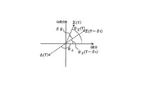
図3に示すように、時刻Tの時点では、和信号Σ(T)の位相ψ Σ(T)は、演算部130が有している時刻T−δtにおける和信号Σ(T−δt)の位相ψΣ(T−δt)よりもδψだけ進んでいる。そこで、方位を高精度に算出するために、演算部130ではタイムラグδtの間に進む和信号Σの位相変化δψを算出し、これを用いて和信号Σ(T−δt)を補正することで、時刻Tにおける和信号Σ(T)を算出している。位相変化δψは、次式で算出することができる。
![]()
![]()
時刻Tにおける補正後の和信号Σ(T)=IΣ(T)+jQΣ(T)は、時刻T−δtにおいて測定された和信号Σ(T−δt)=IΣ(T−δt)+jQΣ(T−δt)に対し位相をδψだけ進めることで求めることができ、回転行列を用いて以下のように算出することができる。
演算部130が有している時刻T−δtにおける和信号Σ(T−δt)を上式を用いて補正することで時刻Tにおける和信号Σ(T)を算出し、これと受信部125から入力した時刻Tにおける差信号Δ(T)とから方位を算出することができる。すなわち、Δ(T)/Σ(T)の虚数部Im(Δ(T)/Σ(T))を求め、あらかじめ方位θと虚数部Im(Δ/Σ)との関係をテーブル形式等で保存しているものを参照することで、時刻Tにおけるターゲットの方位θを算出することができる。
A sum signal Σ (T) at time T is calculated by correcting the sum signal Σ (T−δt) at time T−δt, which the
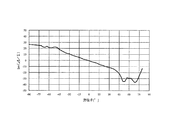
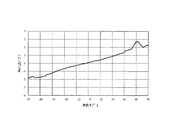
方位θに対する和信号と差信号との比(Δ/Σ)の虚数部の変化の一例を図4に示す。図4に示すような方位θと(Δ/Σ)の虚数部との関係をあらかじめ測定しておき、これをテーブル形式等にして演算部130内のメモリ等に保存しておく。方位演算手段131は、メモリ等から方位θと(Δ/Σ)の虚数部との関係を表したテーブル等を読み出し、これを用いて上記のようにしてターゲットの方位θを算出することができる。
An example of the change of the imaginary part of the ratio (Δ / Σ) of the sum signal and the difference signal with respect to the azimuth θ is shown in FIG. The relationship between the azimuth θ and the imaginary part of (Δ / Σ) as shown in FIG. 4 is measured in advance and stored in a memory or the like in the
なお、上記では方位θと(Δ/Σ)の虚数部との関係を用いて方位を算出する方法について説明したが、受信アンテナ121,122の特性によっては、方位θと(Δ/Σ)の実数部との関係を用いた方が方位を検出しやすい場合がある。その場合には、あらかじめ方位θと(Δ/Σ)の実数部との関係を測定しておき、これをテーブル形式等にして演算部130内のメモリ等に保存しておく。そして、方位演算手段131でも、受信部125から入力した和信号と差信号を用い、上記のように補正した上で両者の比の実数部を算出する。この実数部をメモリ等に保存されているテーブル等を参照して方位θを算出することができる。方位θと(Δ/Σ)の実数部との関係の一例を図5に示す。
In the above description, the method of calculating the azimuth using the relationship between the azimuth θ and the imaginary part of (Δ / Σ) has been described. However, depending on the characteristics of the receiving
上記の実施形態を用いて説明したように、本発明のレーダ装置によれば、1系統の受信部を用いて位相モノパルス方式による方位の測定が可能となり、レーダ装置の小型化及び低価格化を図ることが可能となる。また、受信部が2系統以上ある場合に問題となった受信部間の線路長等の管理が不要となり、取り扱いが容易なレーダ装置を提供することが可能となる。 As described with reference to the above embodiment, according to the radar apparatus of the present invention, it is possible to measure the azimuth by the phase monopulse method using one system of receiving unit, thereby reducing the size and price of the radar apparatus. It becomes possible to plan. In addition, it is possible to provide a radar device that is easy to handle because there is no need to manage the line length between the receiving units, which is a problem when there are two or more receiving units.
なお、本実施の形態における記述は、本発明に係るレーダ装置の一例を示すものであり、これに限定されるものではない。本実施の形態におけるレーダ装置の細部構成及び詳細な動作などに関しては、本発明の趣旨を逸脱しない範囲で適宜変更可能である。 The description in the present embodiment shows an example of the radar apparatus according to the present invention, and the present invention is not limited to this. The detailed configuration and detailed operation of the radar apparatus according to the present embodiment can be changed as appropriate without departing from the spirit of the present invention.
100 レーダ装置
101 送信パルス生成部
102 スイッチ制御部
111 送信部
112 送信アンテナ
121、122 受信アンテナ
123 ハイブリッド回路
124 スイッチ
124a、124b 入力端
124c 出力端
125 受信部
130 演算部
131 方位演算手段
132 距離演算手段
133 相対速度演算手段
140 演算・制御部
DESCRIPTION OF SYMBOLS 100
Claims (8)
前記送信パルス生成部から入力した前記パルス信号を所定の周波数帯にアップコンバートして高周波パルス信号を出力する送信部と、
前記送信部から前記高周波パルス信号を入力して送信波を放射する1つの送信アンテナと、
前記送信アンテナから放射された前記送信波がターゲットで反射されて戻ってきた反射波を受信して2つの受信信号を出力する2以上の受信アンテナと、
前記2以上の受信アンテナから入力した前記2つの受信信号を加算した和信号及び前記2つの受信信号の一方から他方を減算した差信号を出力するハイブリッド回路と、
前記ハイブリッド回路から前記和信号を入力する第1の入力端と、前記差信号を入力する第2の入力端と、所定の選択信号に従って前記第1の入力端または前記第2の入力端に接続されて前記和信号または前記差信号を出力する出力端とを有するスイッチと、
前記スイッチから入力した前記和信号または差信号をIQ復調して相互に位相が直交するI信号及びQ信号を出力する受信部と、
前記受信部から前記I信号及びQ信号を入力し、前記I信号及びQ信号のドップラーシフトによる周波数のずれから前記ターゲットの相対速度を算出するとともに、前記和信号と前記差信号との比を算出して前記ターゲットの方位を算出するする演算部と、を備える
ことを特徴とするレーダ装置。 A transmission pulse generator for generating a pulse signal;
A transmitter that up-converts the pulse signal input from the transmission pulse generator to a predetermined frequency band and outputs a high-frequency pulse signal;
One transmission antenna that radiates a transmission wave by inputting the high-frequency pulse signal from the transmission unit,
Two or more receiving antennas that receive a reflected wave returned from the target reflected by the transmission wave radiated from the transmitting antenna and output two received signals;
A hybrid circuit that outputs a sum signal obtained by adding the two received signals input from the two or more receiving antennas and a difference signal obtained by subtracting the other from one of the two received signals;
Connected to the first input terminal for inputting the sum signal from the hybrid circuit, the second input terminal for inputting the difference signal, and the first input terminal or the second input terminal according to a predetermined selection signal And a switch having an output terminal for outputting the sum signal or the difference signal,
A receiver that IQ-demodulates the sum signal or difference signal input from the switch and outputs an I signal and a Q signal whose phases are orthogonal to each other;
The I signal and the Q signal are input from the receiver, and the relative speed of the target is calculated from the frequency shift caused by the Doppler shift of the I signal and the Q signal, and the ratio of the sum signal and the difference signal is calculated. And a calculation unit for calculating the azimuth of the target.
ことを特徴とする請求項1に記載のレーダ装置。 The switch outputs the sum signal and the difference signal alternately by alternately connecting the first input terminal and the second input terminal to the output terminal. The radar apparatus according to 1.
ことを特徴とする請求項1または2に記載のレーダ装置。 The radar apparatus according to claim 1, wherein the switch periodically switches between the first input terminal and the second input terminal at a predetermined time interval δt.
ことを特徴とする請求項1乃至3のいずれか1項に記載のレーダ装置。 The radar apparatus according to claim 1, further comprising: a switch control unit that outputs the selection signal to the switch when the pulse signal is input from the transmission pulse generation unit.
ことを特徴とする請求項3のまたは4に記載のレーダ装置。 The arithmetic unit is configured such that the I signal and the Q signal of the sum signal or the difference signal input from the receiving unit and the I signal and the Q signal of the difference signal or the sum signal input from the receiving unit last time are the time intervals. 5. The radar apparatus according to claim 3, wherein the azimuth is calculated using a corrected I signal and Q signal obtained by correcting a change amount that changes during δt.
ことを特徴とする請求項5に記載のレーダ装置。 The corrected I signal and Q signal are calculated by correcting the phase change during the time interval δt due to the Doppler shift with respect to the previously input difference signal or sum signal I signal and Q signal. The radar apparatus according to claim 5.
ことを特徴とする請求項1乃至6のいずれか1項に記載のレーダ装置。 The radar apparatus according to claim 1, wherein the arithmetic unit calculates an imaginary part of a ratio between the sum signal and the difference signal to calculate the azimuth of the target.
ことを特徴とする請求項1乃至6のいずれか1項に記載のレーダ装置。
The radar apparatus according to claim 1, wherein the calculation unit calculates a real part of a ratio between the sum signal and the difference signal to calculate the azimuth of the target.
Priority Applications (1)
| Application Number | Priority Date | Filing Date | Title |
|---|---|---|---|
| JP2009069378A JP2010223649A (en) | 2009-03-23 | 2009-03-23 | Radar device |
Applications Claiming Priority (1)
| Application Number | Priority Date | Filing Date | Title |
|---|---|---|---|
| JP2009069378A JP2010223649A (en) | 2009-03-23 | 2009-03-23 | Radar device |
Publications (1)
| Publication Number | Publication Date |
|---|---|
| JP2010223649A true JP2010223649A (en) | 2010-10-07 |
Family
ID=43041006
Family Applications (1)
| Application Number | Title | Priority Date | Filing Date |
|---|---|---|---|
| JP2009069378A Pending JP2010223649A (en) | 2009-03-23 | 2009-03-23 | Radar device |
Country Status (1)
| Country | Link |
|---|---|
| JP (1) | JP2010223649A (en) |
Cited By (1)
| Publication number | Priority date | Publication date | Assignee | Title |
|---|---|---|---|---|
| EP3236278A1 (en) * | 2016-04-20 | 2017-10-25 | Rohde & Schwarz GmbH & Co. KG | Directional antenna module |
Citations (2)
| Publication number | Priority date | Publication date | Assignee | Title |
|---|---|---|---|---|
| JPH11160423A (en) * | 1997-11-28 | 1999-06-18 | Toyota Motor Corp | Radar |
| JP2007155411A (en) * | 2005-12-01 | 2007-06-21 | Tdk Corp | Radar system and high-frequency module |
-
2009
- 2009-03-23 JP JP2009069378A patent/JP2010223649A/en active Pending
Patent Citations (2)
| Publication number | Priority date | Publication date | Assignee | Title |
|---|---|---|---|---|
| JPH11160423A (en) * | 1997-11-28 | 1999-06-18 | Toyota Motor Corp | Radar |
| JP2007155411A (en) * | 2005-12-01 | 2007-06-21 | Tdk Corp | Radar system and high-frequency module |
Cited By (7)
| Publication number | Priority date | Publication date | Assignee | Title |
|---|---|---|---|---|
| EP3236278A1 (en) * | 2016-04-20 | 2017-10-25 | Rohde & Schwarz GmbH & Co. KG | Directional antenna module |
| US20170310003A1 (en) * | 2016-04-20 | 2017-10-26 | Rohde & Schwarz Gmbh & Co. Kg | Directional antenna module and method |
| KR20170120032A (en) * | 2016-04-20 | 2017-10-30 | 로오데운트쉬바르츠게엠베하운트콤파니카게 | Directional antenna module |
| CN107305245A (en) * | 2016-04-20 | 2017-10-31 | 罗德施瓦兹两合股份有限公司 | Directional aerial module |
| US10790584B2 (en) | 2016-04-20 | 2020-09-29 | Rohde & Schwarz Gmbh & Co. Kg | Directional antenna module and method |
| KR102289873B1 (en) * | 2016-04-20 | 2021-08-13 | 로오데운트쉬바르츠게엠베하운트콤파니카게 | Directional antenna module |
| CN107305245B (en) * | 2016-04-20 | 2023-12-22 | 罗德施瓦兹两合股份有限公司 | Directional antenna module |
Similar Documents
| Publication | Publication Date | Title |
|---|---|---|
| JP5639150B2 (en) | Pulse radar apparatus and control method thereof | |
| JP4602267B2 (en) | Electronic scanning radar equipment | |
| US10557933B2 (en) | Radar device and position-determination method | |
| JP4737165B2 (en) | Radar target detection method and radar apparatus using the target detection method | |
| US9234956B2 (en) | Radar device | |
| US9470784B2 (en) | Radar device | |
| WO2019054504A1 (en) | Radar device | |
| JP6947054B2 (en) | Radar device | |
| JP2009080024A (en) | Detection and ranging apparatus and method | |
| JP2009145206A5 (en) | ||
| JP2009121826A (en) | Electronic scanning type radar device | |
| US11885905B2 (en) | Radar apparatus and method for determining range side lobe | |
| JP2007232385A (en) | Electronic scanning type radar | |
| JP6088492B2 (en) | Pulse signal setting device, radar device, pulse signal setting method, and pulse signal setting program | |
| JP2009025158A (en) | Radar device | |
| JP4082442B2 (en) | Direction detection device | |
| JP6019795B2 (en) | Radar apparatus, target data acquisition method, and target tracking system | |
| JP2008122137A (en) | Radar device | |
| JP3829659B2 (en) | Radar equipment | |
| JP2010060459A (en) | Monopulse radar device | |
| JP2009270863A (en) | Bistatic radar system | |
| JP2010223649A (en) | Radar device | |
| JP2006329829A (en) | Radar device | |
| JP5611294B2 (en) | Detecting and ranging device | |
| JP2012194064A (en) | Holographic radar system |
Legal Events
| Date | Code | Title | Description |
|---|---|---|---|
| A621 | Written request for application examination |
Free format text: JAPANESE INTERMEDIATE CODE: A621 Effective date: 20120109 |
|
| A977 | Report on retrieval |
Free format text: JAPANESE INTERMEDIATE CODE: A971007 Effective date: 20130123 |
|
| A131 | Notification of reasons for refusal |
Free format text: JAPANESE INTERMEDIATE CODE: A131 Effective date: 20130405 |
|
| A02 | Decision of refusal |
Free format text: JAPANESE INTERMEDIATE CODE: A02 Effective date: 20130726 |