KR20170095073A - Stabilizer for a vehicle - Google Patents
Stabilizer for a vehicle Download PDFInfo
- Publication number
- KR20170095073A KR20170095073A KR1020160016602A KR20160016602A KR20170095073A KR 20170095073 A KR20170095073 A KR 20170095073A KR 1020160016602 A KR1020160016602 A KR 1020160016602A KR 20160016602 A KR20160016602 A KR 20160016602A KR 20170095073 A KR20170095073 A KR 20170095073A
- Authority
- KR
- South Korea
- Prior art keywords
- vehicle
- bar
- bars
- pair
- actuator
- Prior art date
Links
Images


Classifications
-
- B—PERFORMING OPERATIONS; TRANSPORTING
- B60—VEHICLES IN GENERAL
- B60G—VEHICLE SUSPENSION ARRANGEMENTS
- B60G21/00—Interconnection systems for two or more resiliently-suspended wheels, e.g. for stabilising a vehicle body with respect to acceleration, deceleration or centrifugal forces
- B60G21/02—Interconnection systems for two or more resiliently-suspended wheels, e.g. for stabilising a vehicle body with respect to acceleration, deceleration or centrifugal forces permanently interconnected
- B60G21/04—Interconnection systems for two or more resiliently-suspended wheels, e.g. for stabilising a vehicle body with respect to acceleration, deceleration or centrifugal forces permanently interconnected mechanically
- B60G21/05—Interconnection systems for two or more resiliently-suspended wheels, e.g. for stabilising a vehicle body with respect to acceleration, deceleration or centrifugal forces permanently interconnected mechanically between wheels on the same axle but on different sides of the vehicle, i.e. the left and right wheel suspensions being interconnected
- B60G21/055—Stabiliser bars
- B60G21/0551—Mounting means therefor
- B60G21/0553—Mounting means therefor adjustable
- B60G21/0555—Mounting means therefor adjustable including an actuator inducing vehicle roll
-
- B—PERFORMING OPERATIONS; TRANSPORTING
- B60—VEHICLES IN GENERAL
- B60G—VEHICLE SUSPENSION ARRANGEMENTS
- B60G21/00—Interconnection systems for two or more resiliently-suspended wheels, e.g. for stabilising a vehicle body with respect to acceleration, deceleration or centrifugal forces
- B60G21/02—Interconnection systems for two or more resiliently-suspended wheels, e.g. for stabilising a vehicle body with respect to acceleration, deceleration or centrifugal forces permanently interconnected
- B60G21/026—Interconnection systems for two or more resiliently-suspended wheels, e.g. for stabilising a vehicle body with respect to acceleration, deceleration or centrifugal forces permanently interconnected transversally
-
- B—PERFORMING OPERATIONS; TRANSPORTING
- B60—VEHICLES IN GENERAL
- B60G—VEHICLE SUSPENSION ARRANGEMENTS
- B60G21/00—Interconnection systems for two or more resiliently-suspended wheels, e.g. for stabilising a vehicle body with respect to acceleration, deceleration or centrifugal forces
- B60G21/02—Interconnection systems for two or more resiliently-suspended wheels, e.g. for stabilising a vehicle body with respect to acceleration, deceleration or centrifugal forces permanently interconnected
- B60G21/04—Interconnection systems for two or more resiliently-suspended wheels, e.g. for stabilising a vehicle body with respect to acceleration, deceleration or centrifugal forces permanently interconnected mechanically
- B60G21/05—Interconnection systems for two or more resiliently-suspended wheels, e.g. for stabilising a vehicle body with respect to acceleration, deceleration or centrifugal forces permanently interconnected mechanically between wheels on the same axle but on different sides of the vehicle, i.e. the left and right wheel suspensions being interconnected
- B60G21/055—Stabiliser bars
- B60G21/0551—Mounting means therefor
- B60G21/0553—Mounting means therefor adjustable
-
- B—PERFORMING OPERATIONS; TRANSPORTING
- B60—VEHICLES IN GENERAL
- B60G—VEHICLE SUSPENSION ARRANGEMENTS
- B60G7/00—Pivoted suspension arms; Accessories thereof
- B60G7/001—Suspension arms, e.g. constructional features
-
- B—PERFORMING OPERATIONS; TRANSPORTING
- B60—VEHICLES IN GENERAL
- B60G—VEHICLE SUSPENSION ARRANGEMENTS
- B60G7/00—Pivoted suspension arms; Accessories thereof
- B60G7/005—Ball joints
-
- B—PERFORMING OPERATIONS; TRANSPORTING
- B60—VEHICLES IN GENERAL
- B60G—VEHICLE SUSPENSION ARRANGEMENTS
- B60G2200/00—Indexing codes relating to suspension types
- B60G2200/30—Rigid axle suspensions
- B60G2200/34—Stabilising mechanisms, e.g. for lateral stability
-
- B—PERFORMING OPERATIONS; TRANSPORTING
- B60—VEHICLES IN GENERAL
- B60G—VEHICLE SUSPENSION ARRANGEMENTS
- B60G2202/00—Indexing codes relating to the type of spring, damper or actuator
- B60G2202/40—Type of actuator
- B60G2202/42—Electric actuator
-
- B—PERFORMING OPERATIONS; TRANSPORTING
- B60—VEHICLES IN GENERAL
- B60G—VEHICLE SUSPENSION ARRANGEMENTS
- B60G2204/00—Indexing codes related to suspensions per se or to auxiliary parts
- B60G2204/40—Auxiliary suspension parts; Adjustment of suspensions
- B60G2204/416—Ball or spherical joints
-
- B—PERFORMING OPERATIONS; TRANSPORTING
- B60—VEHICLES IN GENERAL
- B60G—VEHICLE SUSPENSION ARRANGEMENTS
- B60G2204/00—Indexing codes related to suspensions per se or to auxiliary parts
- B60G2204/80—Interactive suspensions; arrangement affecting more than one suspension unit
- B60G2204/82—Interactive suspensions; arrangement affecting more than one suspension unit left and right unit on same axle
-
- B—PERFORMING OPERATIONS; TRANSPORTING
- B60—VEHICLES IN GENERAL
- B60G—VEHICLE SUSPENSION ARRANGEMENTS
- B60G2204/00—Indexing codes related to suspensions per se or to auxiliary parts
- B60G2204/80—Interactive suspensions; arrangement affecting more than one suspension unit
- B60G2204/83—Type of interconnection
- B60G2204/8302—Mechanical
-
- B—PERFORMING OPERATIONS; TRANSPORTING
- B60—VEHICLES IN GENERAL
- B60G—VEHICLE SUSPENSION ARRANGEMENTS
- B60G2206/00—Indexing codes related to the manufacturing of suspensions: constructional features, the materials used, procedures or tools
- B60G2206/01—Constructional features of suspension elements, e.g. arms, dampers, springs
- B60G2206/012—Hollow or tubular elements
-
- B—PERFORMING OPERATIONS; TRANSPORTING
- B60—VEHICLES IN GENERAL
- B60G—VEHICLE SUSPENSION ARRANGEMENTS
- B60G2206/00—Indexing codes related to the manufacturing of suspensions: constructional features, the materials used, procedures or tools
- B60G2206/01—Constructional features of suspension elements, e.g. arms, dampers, springs
- B60G2206/40—Constructional features of dampers and/or springs
- B60G2206/42—Springs
- B60G2206/427—Stabiliser bars or tubes
-
- B—PERFORMING OPERATIONS; TRANSPORTING
- B60—VEHICLES IN GENERAL
- B60G—VEHICLE SUSPENSION ARRANGEMENTS
- B60G2206/00—Indexing codes related to the manufacturing of suspensions: constructional features, the materials used, procedures or tools
- B60G2206/01—Constructional features of suspension elements, e.g. arms, dampers, springs
- B60G2206/70—Materials used in suspensions
- B60G2206/71—Light weight materials
- B60G2206/7102—Aluminium alloys
-
- B—PERFORMING OPERATIONS; TRANSPORTING
- B60—VEHICLES IN GENERAL
- B60G—VEHICLE SUSPENSION ARRANGEMENTS
- B60G2400/00—Indexing codes relating to detected, measured or calculated conditions or factors
- B60G2400/90—Other conditions or factors
- B60G2400/98—Stabiliser movement
Abstract
Description
본 발명은 차량용 스태빌라이저에 관한 것이다. The present invention relates to a vehicle stabilizer.
일반적으로 차량이 선회 또는 롤링 시 차체의 안정성을 향상시키기 위해 스태빌라이저가 구비되는 경우가 많다.In general, a stabilizer is often provided to improve the stability of the vehicle body when the vehicle is turning or rolling.
스태빌라이저는 차량의 앞 바퀴들 사이 또는 뒷 바퀴들 사이에 배치되는데, 스태빌라이저는 차량의 차체가 좌우로 기우는 경우, 액추에이터로부터 발생된 모터의 출력을 감속기를 이용하여 증폭시키고 액추에이터의 회전축에 결합되는 스태빌라이저 바를 회전시킨다. 이와 같이 회전된 스태빌라이저 바는 스태빌라이저 바에 연결된 드랍 링크를 위 아래로 이동시킴으로써 차체를 들어올리거나 내리게 하여 차체의 기울기를 감소시킬 수 있다.The stabilizer is disposed between the front wheels of the vehicle or between the rear wheels. When the vehicle body of the vehicle tilts to the left or right, the stabilizer amplifies the output of the motor generated by the actuator using a speed reducer, Rotate the bar. The stabilized stabilizer bar thus rotated can lift or lower the vehicle body by moving the drop link connected to the stabilizer bar up and down, thereby reducing the inclination of the vehicle body.
그런데, 종래의 스태빌라이저는 스태빌라이저의 액추에이터 하우징이 스태빌라이저 바의 비틀림 강성을 견디기 위한 액추에이터 하우징의 강성을 확보하기 어려웠다. However, in the conventional stabilizer, it is difficult to secure the rigidity of the actuator housing for the actuator housing of the stabilizer to withstand the torsional rigidity of the stabilizer bar.
또한, 액추에이터 양측에 차량의 폭방향으로 배치되는 스태빌라이저 바를 지지하기 의하여 마운팅 베어링 2개만을 사용하여 스태빌라이저를 지지하므로 상대적으로 무거운 액추에이터가 자체 하중에 의하여 쳐짐이 발생하게 되어 스태빌라이저 바가 휨으로써 효율이 저하되는 문제점이 있었다. Further, by supporting the stabilizer bar disposed on both sides of the actuator in the width direction of the vehicle, only the two mounting bearings are supported to support the stabilizer, so that a relatively heavy actuator is struck by its own load and the efficiency of the stabilizer bar is lowered There was a problem.
본 발명의 일 실시예는 스태빌라이저의 액추에이터 하우징의 쳐짐을 방지할 수 있는 차량용 스태빌라이저를 제공하고자 한다. An embodiment of the present invention is intended to provide a stabilizer for a vehicle that can prevent stiction of an actuator housing of a stabilizer.
본 발명의 일 실시예는 스태빌라이저 바가 비틀리지 않으면서도 차체의 안정성을 확보할 수 있도록 차륜에 연결된 차륜 지지체를 상하 방향으로 이동시킬 수 있는 차량용 스태빌라이저를 제공하고자 한다. An embodiment of the present invention is to provide a vehicle stabilizer capable of moving a wheel support body connected to wheels in a vertical direction so as to ensure stability of the vehicle body without tilting the stabilizer bar.
본 발명의 일 측면에 따르면, 차량의 한 쌍의 차륜 사이에 설치되는 차량용 스태빌라이저로서, 차량의 폭방향으로 연장되도록 배치되는 제 1 바; 상기 차량의 차체에 의하여 지지되며, 상기 제 1 바를 상기 차량의 폭 방향으로 이동시킬 수 있도록 상기 제 1 바에 제 1 연결 부재에 의하여 결합되는 액추에이터; 일측이 상기 제 1 바에 연결되고, 타측이 상기 차량의 상기 한 쌍의 차륜 중 어느 하나의 차륜을 지지하는 차륜 지지체의 일측에 연결되는 제 2 바를 포함하되, 상기 제 1 바가 상기 차량의 폭 방향으로 이동함에 따라 상기 제 2 바의 타측이 이동되어 상기 차륜 지지체의 일측을 차량의 상 방향 또는 하 방향으로 이동할 수 있도록 형성되는 차량용 스태빌라이저가 제공된다. According to an aspect of the present invention, there is provided a vehicle stabilizer installed between a pair of wheels of a vehicle, comprising: a first bar arranged to extend in a width direction of a vehicle; An actuator supported by a vehicle body of the vehicle and coupled to the first bar by a first connecting member so as to move the first bar in a width direction of the vehicle; And a second bar connected to one side of a wheel support body, one side of which is connected to the first bar and the other side of which is supported by one of the pair of wheels of the vehicle, The other side of the second bar is moved to move one side of the wheel supporting body in an upward direction or a downward direction of the vehicle.
이 때, 상기 액추에이터는 중공 모터를 포함하며, 상기 제 1 바는 상기 중공 모터를 관통하여 이동가능하도록 상기 중공 모터에 결합될 수 있다. At this time, the actuator includes a hollow motor, and the first bar may be coupled to the hollow motor so as to move through the hollow motor.
이 때, 상기 중공 모터의 중심축은 상기 차륜의 회전축과 나란하게 배치될 수 있다. At this time, the central axis of the hollow motor may be arranged in parallel to the rotation axis of the wheel.
이 때, 상기 제 2 바는 상기 제 1 바의 양 단부에 한 쌍으로 형성되며, 상기 한 쌍의 제 2 바는 각각 상기 차량의 한 쌍의 차륜 각각의 차륜 지지체에 연결되고, 상기 한 쌍의 제 2 바 중 어느 하나가 상측 방향으로 이동할 때, 나머지 어느 하나는 하측 방향으로 이동될 수 있다. At this time, the second bars are formed in pairs at both ends of the first bar, and the pair of second bars are respectively connected to the wheel supports of each of a pair of wheels of the vehicle, When any one of the second bars moves in the upward direction, the other one can be moved in the downward direction.
이 때, 상기 차체의 상기 액추에이터의 양 측부에는 상기 제 1 바를 지지하기 위한 지지 부재가 구비될 수 있다. At this time, on both sides of the actuator of the vehicle body, a support member for supporting the first bar may be provided.
이 때, 상기 차량의 차체에는 상기 제 2 바의 상기 타측의 상하 방향 이동을 지지하기 위한 가이드부가 형성될 수 있다. At this time, the vehicle body may be provided with a guide portion for supporting the other side of the second bar in the up and down direction.
이 때, 상기 제 2 바의 상기 타측에는 제 2 연결 부재에 의하여 결합되는 제 3 바가 연결되며, 상기 제 3 바가 상기 차륜 지지체의 일측에 결합될 수 있다. The third bar may be coupled to the other side of the second bar, and the third bar may be coupled to one side of the wheel support.
이 때, 상기 제 1 연결 부재는 볼 조인트 또는 유니버셜 조인트일 수 있다.In this case, the first connection member may be a ball joint or a universal joint.
이 때, 상기 차륜 지지체는 상기 차륜을 지지하기 위한 어퍼 암, 상기 어퍼 암 하측에 배치되는 로어 암 또는 상기 어퍼 암 및 상기 로어 암 사이에 결합되는 너클 암 중 어느 하나를 포함할 수 있다. At this time, the wheel supporter may include any one of an upper arm for supporting the wheel, a lower arm disposed below the upper arm, or a knuckle arm coupled between the upper arm and the lower arm.
이 때, 상기 제 2 바는 상하 방향으로 연장되되, 하측에서 상측 방향으로 갈수록 차량의 외측 방향으로 경사지게 배치될 수 있다. At this time, the second bar may extend in the vertical direction, and may be inclined toward the outer side of the vehicle from the lower side toward the upper side.
한편, 상기 제 1 바, 상기 액추에이터 및 상기 제 2 바는 한 쌍으로 형성되며, 상기 한 쌍의 제 1 바, 상기 한 쌍의 액추에이터 및 상기 한 쌍의 제 2 바는 상기 차량의 폭 방향으로 좌우 대칭으로 배치될 수 있다. The first bar, the actuator, and the second bar are formed as a pair, and the pair of first bars, the pair of actuators, and the pair of second bars are formed in the width direction of the vehicle They can be arranged symmetrically.
이 때, 상기 한 쌍의 액추에이터에 각각 연결된 한 쌍의 제 1 바는, 상기 한 쌍의 제 2 바 중 어느 하나가 상측 방향으로 이동할 때, 나머지 어느 하나가 하측 방향으로 이동되도록 작동될 수 있다. At this time, a pair of first bars respectively connected to the pair of actuators may be operated such that when one of the pair of second bars moves in the upward direction, the other one is moved in the downward direction.
이 때, 상기 차량의 상기 한 쌍의 차륜은 상기 차량의 전륜 및 후륜 또는 그들 중 어느 하나일 수 있다. At this time, the pair of wheels of the vehicle may be a front wheel and a rear wheel of the vehicle or any one of them.
이 때, 상기 액추에이터의 하우징은 알루미늄 재질로 형성될 수 있다. At this time, the housing of the actuator may be made of aluminum.
본 발명의 일 실시예에 따른 스태빌라이저는 액추에이터가 스태빌라이저 바를 차량의 폭 방향으로 이동시킴으로써 스태빌라이저 바에 연결된 차륜 지지체의 일측을 상하 방향으로 이동시켜 차체의 안정성을 향상시킬 수 있다. The stabilizer according to the embodiment of the present invention can improve the stability of the vehicle body by moving one side of the wheel support connected to the stabilizer bar in the up and down direction by moving the stabilizer bar in the width direction of the vehicle.
또한 본 발명의 일 실시예에 따른 스태빌라이저는 스태빌라이저 바가 비틀리지 않고 차량의 폭 방향으로 움직임으로써 스태빌라이저 액추에이터의 하우징이 비틀리지 않도록 형성될 수 있다. Further, the stabilizer according to an embodiment of the present invention can be formed such that the housing of the stabilizer actuator is not twisted by moving the stabilizer bar in the width direction of the vehicle without twisting.
또한 본 발명의 일 실시예에 따른 스태빌라이저는 액추에이터의 하우징을 알루미늄으로 제작하여 액추에이터의 자체 하중을 가볍게 하여 스태빌라이저 바가 휘어지지 않도록 할 수 있다. In addition, the stabilizer according to an embodiment of the present invention may be made of aluminum to make the actuator's own housing so that the self-load of the actuator is reduced to prevent the stabilizer bar from being bent.
또한, 본 발명의 일 실시예에 따른 스태빌라이저는 액추에이터가 차체에 고정되어 지지되므로 액추에이터가 자체 하중에 의하여 처지는 것이 방지될 수 있다. Further, since the actuator is fixedly supported on the vehicle body, the stabilizer according to the embodiment of the present invention can be prevented from sagging due to its own load.
또한, 본 발명의 일 실시예에 따른 스태빌라이저는 스태빌라이저 바에 연결된 차륜 지지체의 위치에 따라 차체의 기울기 또는 자세를 다양하게 조정할 수 있다. In addition, the stabilizer according to an embodiment of the present invention can variously adjust the inclination or attitude of the vehicle body according to the position of the wheel support connected to the stabilizer bar.
도 1은 본 발명의 제 1 실시예에 따른 차량용 스태빌라이저의 개략적인 구성을 도시한 정면도이다.
도 2는 본 발명의 제 1 실시예에 따른 차량용 스태빌라이저의 액추에이터의 단면도이다.
도 3는 본 발명의 제 1 실시예에 따른 차량용 스태빌라이저의 작동 상태를 나타낸 도면이다.
도 4은 본 발명의 제 1 실시예에 따른 차량용 스태빌라이저의 개략적인 구성을 도시한 평면도이다.
도 5는 본 발명의 제 1 실시예에 따른 차량용 스태빌라이저의 변형예로서, 제3 바가 차량의 너클 암에 결합된 상태의 개략적인 구성을 도시한 정면도이다.
도 6는 본 발명의 제 1 실시예에 따른 차량용 스태빌라이저의 다른 변형예로서, 액추에이터가 횔의 회전축의 전방에 배치된 상태의 개략적인 구성을 도시한 평면도이다.
도 7은 본 발명의 제 2 실시예에 따른 차량용 스태빌라이저의 개략적인 구성을 도시한 정면도이다. 1 is a front view showing a schematic configuration of a vehicle stabilizer according to a first embodiment of the present invention.
2 is a sectional view of an actuator of a vehicle stabilizer according to the first embodiment of the present invention.
3 is a view showing an operating state of the vehicle stabilizer according to the first embodiment of the present invention.
4 is a plan view showing a schematic configuration of a vehicle stabilizer according to the first embodiment of the present invention.
Fig. 5 is a front view showing a schematic configuration of a vehicle stabilizer according to a first embodiment of the present invention, in which the third bar is coupled to a knuckle arm of the vehicle. Fig.
6 is a plan view showing a schematic configuration of a state in which an actuator is disposed in front of a rotary shaft of a vehicle, according to another modification of the vehicle stabilizer according to the first embodiment of the present invention.
7 is a front view showing a schematic configuration of a vehicle stabilizer according to a second embodiment of the present invention.
이하, 첨부한 도면을 참고로 하여 본 발명의 실시예에 대하여 본 발명이 속하는 기술분야에서 통상의 지식을 가진 자가 용이하게 실시할 수 있도록 상세히 설명한다. 본 발명은 여러 가지 상이한 형태로 구현될 수 있으며 여기에서 설명하는 실시예에 한정되지 않는다. 도면에서 본 발명을 명확하게 설명하기 위해서 설명과 관계없는 부분은 생략하였으며, 명세서 전체를 통하여 동일 또는 유사한 구성요소에 대해서는 동일한 참조부호를 붙였다.Hereinafter, exemplary embodiments of the present invention will be described in detail with reference to the accompanying drawings, which will be readily apparent to those skilled in the art to which the present invention pertains. The present invention may be embodied in many different forms and is not limited to the embodiments described herein. In order to clearly illustrate the present invention, parts not related to the description are omitted, and the same or similar components are denoted by the same reference numerals throughout the specification.
도 1은 본 발명의 제 1 실시예에 따른 차량용 스태빌라이저의 개략적인 구성을 도시한 정면도이다. 도 2는 본 발명의 제 1 실시예에 따른 차량용 스태빌라이저의 액추에이터의 단면도이다. 도 3는 본 발명의 제 1 실시예에 따른 차량용 스태빌라이저의 작동 상태를 나타낸 도면이다. 도 4은 본 발명의 제 1 실시예에 따른 차량용 스태빌라이저의 개략적인 구성을 도시한 평면도이다. 도 2에서는 도면의 간략화를 위하여 중공 모터, 원통형 하우징 및 원통형 부재만을 도시하였다. 1 is a front view showing a schematic configuration of a vehicle stabilizer according to a first embodiment of the present invention. 2 is a sectional view of an actuator of a vehicle stabilizer according to the first embodiment of the present invention. 3 is a view showing an operating state of the vehicle stabilizer according to the first embodiment of the present invention. 4 is a plan view showing a schematic configuration of a vehicle stabilizer according to the first embodiment of the present invention. In FIG. 2, only a hollow motor, a cylindrical housing and a cylindrical member are shown for the sake of simplicity.
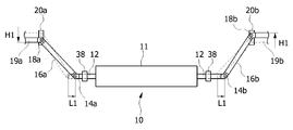
도 1 내지 도 4을 참조하면, 본 발명의 제 1 실시예에 따른 차량용 스태빌라이저(10)는 액추에이터(11), 제 1 바(12), 제 2 바(16a, 16b), 가이드부(20a, 20b) 및 제 3바(19a, 19b)를 포함할 수 있다. 1 to 4, a
본 발명의 제 1 실시예에 따른 차량용 스태빌라이저(10)는 차량(1)의 한 쌍의 차륜(2a, 2b) 사이에 배치되어 차량의 자세를 제어하거나 차체의 기울기를 조절할 수 있도록 형성된다. The
이 때, 차량용 스태빌라이저가 설치되는 차량의 한 쌍의 차륜(2a, 2b)은 차량의 전륜 및 후륜이거나 또는 그들 중 어느 하나일 수 있다. 차량이 전륜 구동, 후륜 구동 또는 4륜 구동인 경우 차량용 스태빌라이저는 구동되는 차륜 사이에 배치될 수 있다. 본 실시예에서는 차량의 후륜에 설치된 예를 중심으로 설명한다. At this time, the pair of
액추에이터(11)는 차량의 폭방향으로 차량의 중심부에 위치되며 차체(3)에 의하여 지지되도록 형성될 수 있다. 이 때, 액추에이터는 액추에이터(11)에 결합된 제 1 바(12)를 차량의 폭 방향으로 이동시키도록 구성된다. The
액추에이터(11)에 결합되는 제 1 바(12)는 차량의 폭 방향으로 연장된 바로 이루어질 수 있다. 이 때, 제 1 바(12)는 단면이 원형이며 일자 형태로 이루어질 수 있으나, 차량의 내부 구조에 따라 일부가 굽어져 연장되는 형태로 이루어질 수도 있다. 또한, 제 1 바(12)는 액추에이터(11)를 중심으로 좌우 대칭으로 이루어질 수 있다. The
도 2를 참조하면, 본 발명의 제 1 실시예에 따른 액추에이터(11)는 중공 모터(34)를 포함할 수 있다. 이 때, 중공 모터(34)는 원통형으로 이루어질 수 있으며, 원통형 하우징(36) 내부에 배치될 수 있다. 도시되지는 아니하였으나, 하우징 내부에는 중공 모터와 결합될 수 있는 감속기 및 베어링 등 공지의 구성 요소들이 구비되어 액추에이터가 구동되도록 형성될 수 있다.Referring to FIG. 2, the
본 발명의 일 실시예에 따르면, 원통형 하우징(36)은 알루미늄 재질로 제작되어 중량이 가볍게 형성될 수 있다. According to an embodiment of the present invention, the
액추에이터(11)의 원통형 하우징(36)은 차량 내부의 차체(3)에 결합되어, 차체(3)에 의하여 지지될 수 있다. The
이와 같이 액추에이터(11)의 하우징(36)이 알루미늄 재질로 형성되며, 차량 내부의 차체(3)에 의하여 안정적으로 지지됨으로써 액추에이터(11)가 자체 중량에 의하여 쳐짐으로써 액추에이터(11)에 의하여 작동되는 제 1 바(12)가 휘어지는 것이 방지될 수 있다. The
제 1 바(12)는 중공 모터(34)를 관통하여 연장되되 중공 모터(34) 내부에 위치되는 치합 구조와 결합하여, 중공 모터(34)의 작동에 따라 제 1 바(12)가 차량의 폭 방향, 즉 차량의 중심을 기준으로 좌측 방향 또는 우측 방향으로 이동하도록 형성될 수 있다. The
예를 들어, 제 1 바(12)의 외주면에는 나사산부가 형성되고, 중공 모터(34)의 내부에는 제 1 바(12)의 외주면에 형성된 나사산부와 치합되는 대응 나사산부가 형성된 원통형 부재(32)가 구비될 수 있다. For example, a threaded portion is formed on the outer circumferential surface of the
이 때, 원통형 부재(32)는 위치가 고정된 상태에서 회전가능하게 형성될 수 있는데, 액추에이터(11)의 작동에 따라 원통형 부재(32)가 회전할 경우 원통형 부재(32)의 회전 방향에 따라 제 1 바(12)가 차량의 폭방향으로 좌측 방향 또는 우측 방향으로 이동될 수 있다. In this case, the
다만, 중공 모터(34)와 결합된 제 1 바(12)의 차폭방향 이동 구조가 이에 제한되는 것은 아니며 제 1 바(12)를 차의 폭방향으로 이동시킬 수 있는 구조라면, 공지된 다양한 액추에이터 구조로도 이루어질 수 있다. 일 예로서, 액추이이터는 리니어 모터 등을 포함하여 제 1 바를 차폭방향으로 이동시키는 구조로 형성될 수 있다. However, the structure of moving the
본 발명의 제 1 실시예에서, 중공 모터(34)를 이용하여 제 1 바(12)를 이동시키도록 구성한 것은, 종래의 액티브 롤 스태빌라이저(Active Roll Stabilizer)가 원통형 액추에이터 구조로 형성된 것과 비교할 때 공간적으로 종래의 액티브 롤 스태빌라이저의 구조와 유사한 형태로 본 발명의 제 1 실시예에 따른 차량용 스태빌라이저를 구성할 수 있기 때문이다. 그러나, 차량 내부의 구조에 따라 원통형이 아닌 다른 형태의 액추에이터를 이용하여 차량용 스태빌라이저를 구성하는 것도 가능하다. In the first embodiment of the present invention, the structure in which the
이 때, 제 1 바(12)가 차폭방향으로 이동하는 동안 제 1 바(12)를 안정적으로 지지하기 위하여 원통형 지지 부재(38), 예를 들어 마운팅 부시가 액추에이터(11)의 양 측부에 구비될 수 있다.At this time, in order to stably support the
한편, 본 발명의 일 실시예에 따르면, 제 1 바(12)의 양 단부에는 한 쌍의 제 2 바(16a, 16b)가 각각 제 1 연결 부재(14a, 14b)에 의하여 연결된다. According to an embodiment of the present invention, a pair of
이 때, 제 2 바(16a, 16b)는 일 단부가 제 1 바(12)에 연결되고 타단부가 차량의 한 쌍의 차륜(2a, 2b) 중 어느 하나의 차륜을 지지하는 차륜 지지체(5a, 5b)의 일측에 결합되도록 형성된다. At this time, the
이 때, 제 2 바(16a, 16b)를 제 1 바(12)의 단부에 결합시키기 위한 제 1 연결 부재(14a, 14b)로서, 볼 조인트 또는 유니버셜 조인트가 사용될 수 있다. 이에 따라, 제 1 바(12)가 회전하면서 측방향으로 이동할 때, 제 1 바(12)의 회전 운동은 제 2 바(16a, 16b)에 전달되지 않고 제 1 바(12)의 측방향 이동만이 제 2 바(16a, 16b)를 이동시키게 된다. At this time, as the first connecting
도 1을 참조하면, 제 2 바(16a, 16b)는 상하 방향으로 연장되되 하측에서 상측 방향으로 갈수록 차량의 중심으로부터 차량의 외측 방향으로 경사지게 배치될 수 있다. Referring to FIG. 1, the
이 때, 제 2 바(16a, 16b)의 상측 단부는 차체에 형성된 가이드부(20a, 20b)에 위치되어 차체에 대하여 상하 방향으로 이동될 수 있도록 형성될 수 있다. At this time, the upper ends of the
차체에 형성된 가이드부(20a, 20b)는 제 2 바(16a, 16b)가 관통되는 상하 방향 홀(미도시)을 구비하여, 제 1 바(12)에 연결된 제 2 바(16a, 16b)의 하측 단부가 제 1 바(12)의 이동에 의하여 차량의 폭 방향으로 이동할 때, 제 2 바(16a, 16b)의 상측 단부가 차량의 상하 방향으로 이동하도록 제 2 바(16a, 16b)의 상측 단부를 안내할 수 있다. 다만, 별도의 가이드부가 제공되지 않고도 제 1 바의 차폭방향 이동이 제 2 바의 상하 방향 이동으로 전달될 수 있는 경우라면 차체에 가이드부를 형성하지 않는 것도 가능할 것이다. The
한편, 본 발명의 일 실시예에 따르면, 제 1 바(12)가 차의 폭방향으로 이동하여 제 2 바(16a, 16b)를 상하 방향으로 이동시키는 경우, 제 1 바(12)가 이동하는 쪽 방향에 위치되는 제 2 바(16b)의 상측 단부는 상측 방향으로 이동되나, 반대편의 제 2 바(16a)의 상측 단부는 하측 방향으로 이동될 수 있다. According to an embodiment of the present invention, when the
예를 들어 도 3에서 볼 때, 우측 방향으로 제 1 바(12)가 소정의 길이(L1)만큼 이동되면, 우측에 위치되는 제 2 바(16b)는 상측 단부가 상측 방향으로 소정의 높이(H1)만큼 높아지도록 이동된다. 이 때, 좌측에 위치되는 제 2 바(16a)는 상측 단부가 하측 방향으로 소정의 높이(H1)만큼 낮아지도록 이동된다. 3, when the
이와 같이 제 1 바(12)의 이동에 따라 한 쌍의 제 2 바(16a, 16b)가 상대적으로 서로 반대 방향으로 이동될 수 있도록 형성됨으로써 제 1 바(12)의 폭 방향 이동 변위가 작더라도 좌우 차륜(2a, 2b)에 연결된 한 쌍의 차륜 지지체(5a, 5b)의 상대적인 움직임의 폭이 증가하여 차량 자세 제어가 보다 잘 이루어질 수 있다. Since the pair of
한편, 제 2 바(16a, 16b)의 상측 단부에는 제 3 바(19a, 19b)가 제 2 결합 부재(18a, 18b)에 의하여 결합될 수 있다. 제 3 바(19a, 19b)는 제 2 바(16a, 16b)의 상측 단부로부터 횡방향 외측으로 연장되어 차량의 차륜 지지체(5a, 5b)의 일측에 결합될 수 있다. 이 때, 제 3 바(19a, 19b)를 제 2 바(16a, 16b)와 결합시키는 제 2 연결 부재(18a, 18b)는 볼 조인트 또는 유니버셜 조인트일 수 있다. On the other hand, the
제 3 바(19a, 19b)는 제 2 바(16a, 16b)의 상측 단부가 상하 방향으로 이동할 때 제 2 바(16a, 16b)의 상측 단부의 이동과 연동하여 상하 방향으로 이동되며, 이와 같은 제 3 바(19a, 19b)의 상하 방향 이동에 따라 제 3 바(19a, 19b)에 결합된 차륜 지지체(5a, 5b)의 일측이 상하 방향으로 이동될 수 있다. The
만일, 구조적으로 제 2 바(16a, 16b)가 차륜 지지체(5a, 5b)에 직접 연결될 수 있는 경우에는 제 2 바(16a, 16b)에 연결된 제 3 바(19a, 19b) 및 제 2 연결 부재(18a, 18b)를 생략하는 것도 가능하다. If the
한편, 본 발명의 일 실시예에 따르면, 제 3 바(19a, 19b)에 결합된 차륜 지지체(5a, 5b)는 차륜을 지지하기 위한 어퍼 암(Upper Arm) (8a, 8b)이거나, 어퍼 암 하측에 배치되는 로어 암(Lower Arm) (9a, 9b)이거나 또는 어퍼 암 및 로어 암 사이에 상하 방향으로 배치되는 너클 암(Knuckle Arm)(6a, 6b)를 포함할 수 있다. According to an embodiment of the present invention, the wheel supports 5a and 5b coupled to the
이 때, 제 3 바(19a, 19b)는 어퍼 암(8a, 8b)의 일측, 로어 암(9a, 9b)의 일측 또는 너클 암(6a, 6b)의 일측 중 어느 하나에 결합될 수 있다. 이 때, 제 3 바(19a, 19b)가 결합되는 위치에 따라 차량용 액추에이터의 작동에 의한 효과가 달라질 수 있다. At this time, the
보다 상세히, 본 발명의 제 1 실시예에서는, 도 1에 도시된 바와 같이 제 3 바(19a, 19b)가 어퍼 암(8a, 8b)의 일측에 결합된다. 이와 같이 제 3 바(19a, 19b)가 어퍼 암(8a, 8b)에 결합되면, 본 발명의 일 실시예에 따른 차량용 스태빌라이저의 작동에 따라 어퍼 암(8a, 8b)의 일측이 상하방향으로 이동될 수 있다. 이와 같은 어퍼 암(8a, 8b)의 일측의 상하 방향 이동은 차량의 캠버 각(camber angle)을 제어하는 효과를 가져올 수 있다. More specifically, in the first embodiment of the present invention, as shown in Fig. 1, the
본 발명의 제 1 실시예에서는 제 3 바(19a, 19b)가 어퍼 암(8a, 8b)의 일측에 결합된 구조를 예시하였으나, 제 3 바(19a, 19b)는 도 5에 도시된 바와 같이 너클 암(6a, 6b)의 일측에 결합될 수도 있다. 이와 같이 제 3 바(19a, 19b)가 너클 암(6a, 6b)의 일측에 결합되면 차량용 스태빌라이저의 작동에 따라 너클 암(6a, 6b)의 각도가 조절되어 토각(toe angle)을 제어할 수 있는 효과가 있다. In the first embodiment of the present invention, the structure in which the
또한, 도시되지는 아니하였으나, 제 3 바(19a, 19b)는 로어 암(9a, 9b)에 연결되는 스텝 링크(step link) 등에 연결되어 차체의 기울기나 자세를 조정할 수도 있다. Also, although not shown, the
한편, 본 발명의 제 1 실시예에 따른 차량용 스태빌라이저(10)는 액추에이터(11)의 중공 모터(34)의 중심축(C1)이 차륜의 회전축(4a, 4b)과 나란하게 배치되며, 도 4에 도시된 바와 같이 차량의 전후 방향으로 볼 때 중공 모터(34)의 중심축 (C1)이 차륜의 회전축(4a, 4b)과 동일 평면 상에 배치된다. The
이와 같이 중공 모터(34)의 중심축(C1)이 차륜의 회전축(4a, 4b)과 나란하게 동일 평면 상에 배치됨으로써 중공 모터(34)의 중심축 상에서 제 1 바(12)가 이동하는 힘이 제 2 바(16a, 16b)의 상하 방향으로 이동하는 힘으로 전달될 때 차량의 전후 방향으로 분산되지 않고 전달될 수 있다. The central axis C1 of the
이 때, 액추에이터(11)의 위치는 도 4에 도시된 바와 같이 차량의 전후 방향으로 볼 때 중공 모터(34)의 중심축(C1)이 차륜의 회전축(4a, 4b)과 동일 평면 상에 배치되는 것이 바람직하지만, 차체 내부 구조적으로 중공 모터(34)의 중심축(C1)이 차량의 전후 방향으로 볼 때 차륜의 회전축(4a, 4b)과 동일 평면 상에 놓이기 어려운 경우라면, 도 6에 도시된 바와 같이 액추에이터(11)가 차륜의 회전축(4a, 4b)의 전방에 배치되도록 구성하는 것도 가능하다. 4, the central axis C1 of the
이와 같은 경우 제 2 바(16a, 16b)의 상단 부분 및 제 3 바(19a, 19b)의 위치 및 작동은 제 1 실시예서와 동일하게 구성되나, 액추에이터(11)의 위치 변화에 따라 제 1 바(12)의 길이, 제 1 바(12)와 제 2 바(16a, 16b)를 결합시키는 제 1 연결 부재(14a, 14b)의 결합 상태 및 제 2 바(16a, 16b)의 길이 등은 필요에 따라 적절히 조절되어 차체에 설치될 수 있다. In this case, the upper part of the
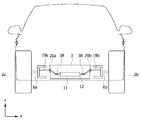
도 7은 본 발명의 제 2 실시예에 따른 차량용 스태빌라이저의 개략적인 구성을 도시한 정면도이다. 7 is a front view showing a schematic configuration of a vehicle stabilizer according to a second embodiment of the present invention.
도 7을 참조하면, 본 발명의 제 2 실시예에 따른 차량용 스태빌라이저(110)는 액추에이터(111a, 111b) 및 제 1 바(112a, 112b)가 차량의 폭 방향 중심을 기준으로 좌우 한 쌍으로 이루어진다. 7, the stabilizer 110 for a vehicle according to the second embodiment of the present invention includes a pair of left and right actuators 111a and 111b and first bars 112a and 112b on the basis of the widthwise center of the vehicle .
이 때, 한 쌍의 제 1 바(112a, 112b), 한 쌍의 액추에이터(111a, 111b) 및 한 쌍의 제 2 바(116a, 116b)는 차량의 폭 방향으로 좌우 대칭으로 배치될 수 있다. At this time, the pair of first bars 112a and 112b, the pair of actuators 111a and 111b, and the pair of second bars 116a and 116b may be arranged symmetrically in the width direction of the vehicle.
제 2 실시예에 따른 차량용 스태빌라이저(110)는 제 1 바(112a, 112b) 및 액추에이터(111a, 111b)의 구성을 제외하고는 제 1 실시예와 동일한 구성으로 이루어질 수 있다. 이하 제 2 실시예를 설명함에 있어 제 1 실시예와 동일한 구성에 대하여는 설명을 생략하고, 제 1 실시예와 구별되는 구성을 중심으로 설명한다. The stabilizer 110 for a vehicle according to the second embodiment may have the same configuration as that of the first embodiment except for the configuration of the first bars 112a and 112b and the actuators 111a and 111b. In the following description of the second embodiment, description of the same configuration as that of the first embodiment will be omitted, and the configuration different from the first embodiment will be mainly described.
본 발명의 제 2 실시예에 따르면, 제 1 바(112a, 112b)는 액추에이터(111a, 111b)의 차량 폭 방향 외측으로 연장되도록 배치될 수 있다. According to the second embodiment of the present invention, the first bars 112a and 112b may be arranged to extend outwardly in the vehicle width direction of the actuators 111a and 111b.
제 1 바(112a, 112b)를 차량의 폭 방향으로 이동시키는 액추에이터(111a, 111b)는 제 1 실시예와 유사하게 중공 모터 형으로 이루어지거나 중공 모터 이외의 리니어 모터로 이루어질 수 있다. Actuators 111a and 111b for moving the first bars 112a and 112b in the width direction of the vehicle may be hollow motor type similar to the first embodiment or linear motors other than the hollow motor.
본 발명의 제 2 실시예에서와 같이 액추에이터(111a, 111b)를 한 쌍으로 형성하고, 각각 한 쌍의 액추에이터(111a, 111b)에 제 1 바(112a, 112b)를 결합시키는 경우 제 1 바(112a, 112b)가 차량의 중심을 가로질러 연장될 필요가 없으므로 차체 내부에 설치되는 구조를 제 1 실시예에서보다 자유롭게 구성할 수 있다.When the actuators 111a and 111b are formed as a pair and the first bars 112a and 112b are coupled to the pair of actuators 111a and 111b as in the second embodiment of the present invention, 112a, 112b do not need to extend across the center of the vehicle, the structure provided inside the vehicle body can be freely configured in the first embodiment.
이 때, 제 2 실시예에 따른 차량용 스태빌라이저(110)는 제 1 실시예와 유사하게 구동되도록 하기 위하여 한 쌍의 제 1 바(112a, 112b)의 외측 단부 사이의 거리를 일정하게 유지할 필요가 있다. At this time, the vehicle stabilizer 110 according to the second embodiment needs to maintain a constant distance between the outer ends of the pair of first bars 112a, 112b in order to be driven similarly to the first embodiment .
즉, 도 7에서 우측에 위치되는 제 1 바(112b)의 외측 단부를 우측 방향으로 이동시킬 경우 좌측에 위치되는 제 1 바(112a)의 외측 단부는 좌측 방향으로 이동시켜야 하며, 이와 같이 한 쌍의 제 1 바(112a, 112b)의 외측 단부 사이의 거리(W)를 일정하게 유지시키기 위하여 별도의 제어부가 구비될 필요가 있다. That is, when the outer end of the first bar 112b located on the right side in FIG. 7 is moved to the right, the outer end of the first bar 112a located on the left should be moved to the left, It is necessary to provide a separate control unit to keep the distance W between the outer ends of the first bars 112a,
이와 같이 구성됨으로써, 한 쌍의 액추에이터(111a, 111b)에 각각 연결된 한 쌍의 제 1 바(112a, 112b)는, 한 쌍의 제 2 바(116a, 116b) 중 어느 하나가 상측 방향으로 이동할 때, 나머지 어느 하나가 하측 방향으로 이동되도록 작동할 수 있다. The pair of first bars 112a and 112b connected to the pair of actuators 111a and 111b is configured such that when one of the pair of second bars 116a and 116b moves upward , And the other one of them is moved in the downward direction.
다만, 제 1 실시예서와 달리 한 쌍의 액추에이터(111a, 111b)가 각각 좌우 차륜의 차륜 지지체와 연결되므로 한 쌍의 액추에이터(111a, 111b)가 연동하여 좌우 차륜의 차륜 지지체를 제어하지 않고 좌우 차륜을 개별적으로 제어하거나 혹은 하나의 액추에이터만 제어하여 차륜 지지체를 제어할 수도 있다. However, unlike the first embodiment, the pair of actuators 111a and 111b are connected to the wheel supports of the left and right wheels, respectively, so that the pair of actuators 111a and 111b are interlocked to control the left and right wheels, Or only one actuator may be controlled to control the wheel support.
본 발명의 여러 실시예에 따른 차량용 스태빌라이저는 액추에이터에 의하여 이동되는 제 1 바가 차의 폭방향으로 이동하는 동작에 의하여 제 1 바에 연결된 제 2 바 및 제 3 바가 이동하여 차륜의 지지체가 상하 방향으로 이동하거나 움직이도록 작동되므로, 액추에이터의 하우징이 비틀리지 않도록 형성되어 비틀림 강성을 견뎌야 할 정도로 강한 재질로 이루어질 필요가 없다. In the stabilizer for a vehicle according to various embodiments of the present invention, the first bar moved by the actuator moves in the width direction of the car, the second bar and the third bar connected to the first bar move and the support of the wheel moves up and down So that the housing of the actuator does not need to be formed of a material that is strong enough to withstand torsional rigidity.
따라서, 본 발명의 여러 실시예에 따른 스태빌라이저에 사용될 수 있는 액추에이터의 하우징은 알루미늄과 같은 재질로 형성될 수 있어 중량이 가벼워질 수 있고, 액추에이터가 차체에 고정되도록 형성됨으로써 액추에이터 자체 중량에 따른 치우침을 방지할 수 있기 때문에 액추에이터에 연결된 제 1 바의 휘어짐 등에 따른 스태빌라이저 작동 효율 저하 등을 방지할 수 있다. Therefore, the housing of the actuator, which can be used in the stabilizer according to various embodiments of the present invention, can be formed of a material such as aluminum and can be made lighter in weight, and the actuator is formed to be fixed to the vehicle body, It is possible to prevent the stabilizer operation efficiency from being lowered due to warping of the first bar connected to the actuator.
이상에서 본 발명의 일 실시예에 대하여 설명하였으나, 본 발명의 사상은 본 명세서에 제시되는 실시 예에 제한되지 아니하며, 본 발명의 사상을 이해하는 당업자는 동일한 사상의 범위 내에서, 구성요소의 부가, 변경, 삭제, 추가 등에 의해서 다른 실시 예를 용이하게 제안할 수 있을 것이나, 이 또한 본 발명의 사상범위 내에 든다고 할 것이다.While the present invention has been particularly shown and described with reference to exemplary embodiments thereof, it is to be understood that the invention is not limited to the disclosed exemplary embodiments, It will be understood by those skilled in the art that various changes in form and details may be made therein without departing from the spirit and scope of the invention as defined by the appended claims.
1 차량
2a 2b 차륜
3 차체
4a 4b 회전축
6a 6b 너클 암
8a 8b 어퍼 암
9a 9b 로어 암
10 110 차량용 스태빌라이저
11 111a 111b 액추에이터
12 112a 112b 제 1 바
14a 14b 제 1 연결 부재
16a 16b 116a 116b 제 2 바
18a 18b 제 2 연결 부재
19a 19b 제 3 바
20a 20b 가이드부1
3
9a
11 111a 111b
Claims (14)
차량의 폭방향으로 연장되도록 배치되는 제 1 바;
상기 차량의 차체에 의하여 지지되며, 상기 제 1 바를 상기 차량의 폭 방향으로 이동시킬 수 있도록 상기 제 1 바에 제 1 연결 부재에 의하여 결합되는 액추에이터;
일측이 상기 제 1 바에 연결되고, 타측이 상기 차량의 상기 한 쌍의 차륜 중 어느 하나의 차륜을 지지하는 차륜 지지체의 일측에 연결되는 제 2 바를 포함하되,
상기 제 1 바가 상기 차량의 폭 방향으로 이동함에 따라 상기 제 2 바의 타측이 이동되어 상기 차륜 지지체의 일측을 차량의 상 방향 또는 하 방향으로 이동할 수 있도록 형성되는 차량용 스태빌라이저. A vehicle stabilizer installed between a pair of wheels of a vehicle,
A first bar disposed to extend in a width direction of the vehicle;
An actuator supported by a vehicle body of the vehicle and coupled to the first bar by a first connecting member so as to move the first bar in a width direction of the vehicle;
And a second bar connected to one side of a wheel support body, one side of which is connected to the first bar and the other side of which is supported by one of the pair of wheels of the vehicle,
And the other side of the second bar is moved as the first bar moves in the width direction of the vehicle so that one side of the wheel support body can be moved upward or downward of the vehicle.
상기 액추에이터는 중공 모터를 포함하며,
상기 제 1 바는 상기 중공 모터를 관통하여 이동가능하도록 상기 중공 모터에 결합되는, 차량용 스태빌라이저.The method according to claim 1,
Wherein the actuator includes a hollow motor,
And the first bar is coupled to the hollow motor so as to be movable through the hollow motor.
상기 중공 모터의 중심축은 상기 차륜의 회전축과 나란하게 배치되는, 차량용 스태빌라이저. 3. The method of claim 2,
And the central axis of the hollow motor is disposed in parallel to the rotation axis of the wheel.
상기 제 2 바는 상기 제 1 바의 양 단부에 한 쌍으로 형성되며,
상기 한 쌍의 제 2 바는 각각 상기 차량의 한 쌍의 차륜 각각의 차륜 지지체에 연결되고,
상기 한 쌍의 제 2 바 중 어느 하나가 상측 방향으로 이동할 때, 나머지 어느 하나는 하측 방향으로 이동되는 차량용 스태빌라이저. 3. The method of claim 2,
The second bars are formed in pairs at both ends of the first bars,
Each of the pair of second bars being connected to a wheel support of each of a pair of wheels of the vehicle,
And when one of the pair of second bars moves in the upward direction, the other one of the second bars moves in the downward direction.
상기 차체의 상기 액추에이터의 양 측부에는 상기 제 1 바를 지지하기 위한 지지 부재가 구비되는 차량용 스태빌라이저.5. The method of claim 4,
And a support member for supporting the first bar is provided on both side portions of the actuator of the vehicle body.
상기 차량의 차체에는 상기 제 2 바의 상기 타측의 상하 방향 이동을 지지하기 위한 가이드부가 형성되는, 차량용 스태빌라이저.The method according to claim 1,
Wherein a guide portion for supporting a vertical movement of the other side of the second bar is formed in a vehicle body of the vehicle.
상기 제 2 바의 상기 타측에는 제 2 연결 부재에 의하여 결합되는 제 3 바가 연결되며, 상기 제 3 바가 상기 차륜 지지체의 일측에 결합되는, 차량용 스태빌라이저.The method according to claim 1,
And a third bar coupled to the other side of the second bar by a second connecting member is connected, and the third bar is coupled to one side of the wheel support.
상기 제 1 연결 부재는 볼 조인트 또는 유니버셜 조인트인, 차량용 스태빌라이저.The method according to claim 1,
Wherein the first connecting member is a ball joint or a universal joint.
상기 차륜 지지체는 상기 차륜을 지지하기 위한 어퍼 암, 상기 어퍼 암 하측에 배치되는 로어 암 또는 상기 어퍼 암 및 상기 로어 암 사이에 결합되는 너클 암 중 어느 하나를 포함하는, 차량용 스태빌라이저.The method according to claim 1,
Wherein the wheel support includes any one of an upper arm for supporting the wheel, a lower arm disposed below the upper arm, or a knuckle arm coupled between the upper arm and the lower arm.
상기 제 2 바는 상하 방향으로 연장되되, 하측에서 상측 방향으로 갈수록 차량의 외측 방향으로 경사지게 배치되는, 차량용 스태빌라이저. The method according to claim 1,
And the second bar extends in the vertical direction, and is arranged to be inclined toward the outer side of the vehicle from the lower side toward the upper side.
상기 제 1 바, 상기 액추에이터 및 상기 제 2 바는 한 쌍으로 형성되며,
상기 한 쌍의 제 1 바, 상기 한 쌍의 액추에이터 및 상기 한 쌍의 제 2 바는 상기 차량의 폭 방향으로 좌우 대칭으로 배치되는, 차량용 스태빌라이저.The method according to claim 1,
Wherein the first bar, the actuator and the second bar are formed as a pair,
Wherein the pair of first bars, the pair of actuators and the pair of second bars are arranged symmetrically in the width direction of the vehicle.
상기 한 쌍의 액추에이터에 각각 연결된 한 쌍의 제 1 바는, 상기 한 쌍의 제 2 바 중 어느 하나가 상측 방향으로 이동할 때, 나머지 어느 하나가 하측 방향으로 이동되도록 작동하는, 차량용 스태빌라이저.12. The method of claim 11,
Wherein a pair of first bars respectively connected to the pair of actuators are operated such that when one of the pair of second bars moves in the upward direction, the other one of the pair of bars is moved in the downward direction.
상기 차량의 상기 한 쌍의 차륜은 상기 차량의 전륜 및 후륜 또는 그들 중 어느 하나인, 차량용 스태빌라이저. The method according to claim 1,
Wherein the pair of wheels of the vehicle are the front and rear wheels of the vehicle or one of them.
상기 액추에이터의 하우징은 알루미늄 재질로 형성되는, 차량용 스태빌라이저. The method according to claim 1,
Wherein the housing of the actuator is formed of an aluminum material.
Priority Applications (4)
| Application Number | Priority Date | Filing Date | Title |
|---|---|---|---|
| KR1020160016602A KR102449420B1 (en) | 2016-02-12 | 2016-02-12 | Stabilizer for a vehicle |
| US15/429,912 US10052930B2 (en) | 2016-02-12 | 2017-02-10 | Stabilizer for vehicle |
| DE102017001382.9A DE102017001382B4 (en) | 2016-02-12 | 2017-02-13 | Stabilizer for a vehicle |
| CN201710094790.8A CN107082004B (en) | 2016-02-12 | 2017-02-13 | Vehicle stabilizer |
Applications Claiming Priority (1)
| Application Number | Priority Date | Filing Date | Title |
|---|---|---|---|
| KR1020160016602A KR102449420B1 (en) | 2016-02-12 | 2016-02-12 | Stabilizer for a vehicle |
Publications (2)
| Publication Number | Publication Date |
|---|---|
| KR20170095073A true KR20170095073A (en) | 2017-08-22 |
| KR102449420B1 KR102449420B1 (en) | 2022-09-30 |
Family
ID=59410600
Family Applications (1)
| Application Number | Title | Priority Date | Filing Date |
|---|---|---|---|
| KR1020160016602A KR102449420B1 (en) | 2016-02-12 | 2016-02-12 | Stabilizer for a vehicle |
Country Status (4)
| Country | Link |
|---|---|
| US (1) | US10052930B2 (en) |
| KR (1) | KR102449420B1 (en) |
| CN (1) | CN107082004B (en) |
| DE (1) | DE102017001382B4 (en) |
Cited By (12)
| Publication number | Priority date | Publication date | Assignee | Title |
|---|---|---|---|---|
| KR20200093407A (en) | 2019-01-26 | 2020-08-05 | 장순길 | Stabilizer for vehicle |
| US11173766B1 (en) | 2017-09-07 | 2021-11-16 | Apple Inc. | Suspension system with locking structure |
| US11179991B1 (en) | 2019-09-23 | 2021-11-23 | Apple Inc. | Suspension systems |
| US11285773B1 (en) | 2018-09-12 | 2022-03-29 | Apple Inc. | Control system |
| US11345209B1 (en) * | 2019-06-03 | 2022-05-31 | Apple Inc. | Suspension systems |
| US11358431B2 (en) | 2017-05-08 | 2022-06-14 | Apple Inc. | Active suspension system |
| US11634167B1 (en) | 2018-09-14 | 2023-04-25 | Apple Inc. | Transmitting axial and rotational movement to a hub |
| US11702065B1 (en) | 2017-06-21 | 2023-07-18 | Apple Inc. | Thermal management system control |
| US11707961B1 (en) | 2020-04-28 | 2023-07-25 | Apple Inc. | Actuator with reinforcing structure for torsion resistance |
| US11828339B1 (en) | 2020-07-07 | 2023-11-28 | Apple Inc. | Vibration control system |
| US11938922B1 (en) | 2019-09-23 | 2024-03-26 | Apple Inc. | Motion control system |
| US11945279B1 (en) | 2015-03-18 | 2024-04-02 | Apple Inc. | Motion control system |
Families Citing this family (1)
| Publication number | Priority date | Publication date | Assignee | Title |
|---|---|---|---|---|
| DE102017207118A1 (en) * | 2017-04-27 | 2018-10-31 | Zf Friedrichshafen Ag | Anti-roll stabilizer and use of a roll stabilizer in a motor vehicle |
Citations (4)
| Publication number | Priority date | Publication date | Assignee | Title |
|---|---|---|---|---|
| JP2007210456A (en) * | 2006-02-09 | 2007-08-23 | Toyota Motor Corp | Vehicle stabilizer system |
| KR20070111159A (en) * | 2006-05-17 | 2007-11-21 | 현대자동차주식회사 | Stabilizer system for vehicle |
| JP2008001236A (en) * | 2006-06-22 | 2008-01-10 | Toyota Motor Corp | Travel control device for vehicle |
| KR20130012295A (en) * | 2011-07-25 | 2013-02-04 | 현대자동차주식회사 | Active roll control system |
Family Cites Families (12)
| Publication number | Priority date | Publication date | Assignee | Title |
|---|---|---|---|---|
| US4484767A (en) * | 1982-03-23 | 1984-11-27 | Klem Richard H | Anti-sway suspension |
| US4534575A (en) | 1982-10-18 | 1985-08-13 | Jlg Industries, Inc. | Vehicle suspension and steerage system |
| DE3928062A1 (en) | 1989-08-25 | 1990-11-29 | Daimler Benz Ag | Balancing system for independently suspended wheels - has control unit which carries two oppositely positioned level adjustment members with drive arrangement with worm drive |
| JPH09272318A (en) * | 1996-04-08 | 1997-10-21 | Honda Motor Co Ltd | Suspension device for vehicle |
| EP1731336B1 (en) * | 2005-06-06 | 2009-08-12 | Delphi Technologies, Inc. | Variable rate torsion control system for vehicle suspension |
| KR20090020803A (en) * | 2007-08-24 | 2009-02-27 | 현대자동차주식회사 | Stabilizer for vehicle |
| GB2460860B (en) | 2008-06-12 | 2012-09-05 | Mclaren Automotive Ltd | Vehicle |
| US8070169B2 (en) * | 2008-07-10 | 2011-12-06 | Hyundai Motor Company | Actuator for active roll control system |
| DE102009027349A1 (en) * | 2009-06-30 | 2011-01-05 | Ford Global Technologies, LLC, Dearborn | Motor vehicle axle, has middle link part moved in vehicle transverse direction, and Watts link along with middle link point arranged in sliding slot using watt coupler that is vertically arranged in idle position |
| KR101393561B1 (en) * | 2012-12-31 | 2014-05-27 | 현대자동차 주식회사 | Active roll control system |
| DE102013002714B4 (en) * | 2013-02-16 | 2016-06-30 | Audi Ag | Torsion spring arrangement for a wheel suspension of a motor vehicle |
| DE102013011562A1 (en) * | 2013-07-11 | 2015-01-15 | Audi Ag | Subframe for a motor vehicle |
-
2016
- 2016-02-12 KR KR1020160016602A patent/KR102449420B1/en active IP Right Grant
-
2017
- 2017-02-10 US US15/429,912 patent/US10052930B2/en active Active
- 2017-02-13 CN CN201710094790.8A patent/CN107082004B/en active Active
- 2017-02-13 DE DE102017001382.9A patent/DE102017001382B4/en active Active
Patent Citations (4)
| Publication number | Priority date | Publication date | Assignee | Title |
|---|---|---|---|---|
| JP2007210456A (en) * | 2006-02-09 | 2007-08-23 | Toyota Motor Corp | Vehicle stabilizer system |
| KR20070111159A (en) * | 2006-05-17 | 2007-11-21 | 현대자동차주식회사 | Stabilizer system for vehicle |
| JP2008001236A (en) * | 2006-06-22 | 2008-01-10 | Toyota Motor Corp | Travel control device for vehicle |
| KR20130012295A (en) * | 2011-07-25 | 2013-02-04 | 현대자동차주식회사 | Active roll control system |
Cited By (14)
| Publication number | Priority date | Publication date | Assignee | Title |
|---|---|---|---|---|
| US11945279B1 (en) | 2015-03-18 | 2024-04-02 | Apple Inc. | Motion control system |
| US11701942B2 (en) | 2017-05-08 | 2023-07-18 | Apple Inc. | Motion control system |
| US11358431B2 (en) | 2017-05-08 | 2022-06-14 | Apple Inc. | Active suspension system |
| US11702065B1 (en) | 2017-06-21 | 2023-07-18 | Apple Inc. | Thermal management system control |
| US11173766B1 (en) | 2017-09-07 | 2021-11-16 | Apple Inc. | Suspension system with locking structure |
| US11285773B1 (en) | 2018-09-12 | 2022-03-29 | Apple Inc. | Control system |
| US11634167B1 (en) | 2018-09-14 | 2023-04-25 | Apple Inc. | Transmitting axial and rotational movement to a hub |
| KR20200093407A (en) | 2019-01-26 | 2020-08-05 | 장순길 | Stabilizer for vehicle |
| US11345209B1 (en) * | 2019-06-03 | 2022-05-31 | Apple Inc. | Suspension systems |
| US11731476B1 (en) | 2019-09-23 | 2023-08-22 | Apple Inc. | Motion control systems |
| US11938922B1 (en) | 2019-09-23 | 2024-03-26 | Apple Inc. | Motion control system |
| US11179991B1 (en) | 2019-09-23 | 2021-11-23 | Apple Inc. | Suspension systems |
| US11707961B1 (en) | 2020-04-28 | 2023-07-25 | Apple Inc. | Actuator with reinforcing structure for torsion resistance |
| US11828339B1 (en) | 2020-07-07 | 2023-11-28 | Apple Inc. | Vibration control system |
Also Published As
| Publication number | Publication date |
|---|---|
| CN107082004A (en) | 2017-08-22 |
| DE102017001382A1 (en) | 2017-08-17 |
| DE102017001382B4 (en) | 2022-01-20 |
| US10052930B2 (en) | 2018-08-21 |
| CN107082004B (en) | 2019-05-07 |
| KR102449420B1 (en) | 2022-09-30 |
| US20170232812A1 (en) | 2017-08-17 |
Similar Documents
| Publication | Publication Date | Title |
|---|---|---|
| KR20170095073A (en) | Stabilizer for a vehicle | |
| JP5019026B2 (en) | Traveling vehicle | |
| US8714574B2 (en) | Independent wheel suspension of an at least slightly steerable rear wheel of a double-track vehicle | |
| JP4460831B2 (en) | Vehicle wheel suspension system | |
| JP2003002024A (en) | Suspension device permitting camber angle change | |
| JP2015512821A (en) | Integrated system of independent variable multi-wheel steering and road contact geometry | |
| JP2003118338A (en) | Suspension system provided with slider enabling camber | |
| JP2007055486A (en) | Suspension device | |
| JP2019093992A (en) | Wheel steering gear | |
| CN107074051A (en) | Wheel suspension with the horizontal leaf spring pivoted in centre | |
| WO2007007501A1 (en) | Suspension device for vehicle | |
| CN1671567B (en) | Suspension system for a vehicle wheel | |
| JP2010052583A (en) | Rear suspension device | |
| JPH04108011A (en) | Wheel suspension device for steerable rear wheel of automobile | |
| JP2022031831A (en) | Dual-axle wheels suspension | |
| CN114206636A (en) | Wheel suspension system with movable steering axis | |
| KR20120064539A (en) | Active geometry control suspension system | |
| JP7236387B2 (en) | Motor vehicle with two front steering wheels with improved steering mechanism | |
| JP2017537024A (en) | Control arm system | |
| KR20090064976A (en) | Front suspension with controllable steering characteristics | |
| JP2005506922A (en) | Method and apparatus for suspending a vehicle wheel assembly | |
| KR100767511B1 (en) | A stabilizer having adjustable rigidity | |
| JP7103022B2 (en) | Suspension structure | |
| JP2016016752A (en) | Rear wheel suspension device | |
| US8528922B2 (en) | Chassis |
Legal Events
| Date | Code | Title | Description |
|---|---|---|---|
| E902 | Notification of reason for refusal | ||
| E701 | Decision to grant or registration of patent right | ||
| GRNT | Written decision to grant |