KR20170088344A - Camera module, manufacturing method of camera module, imaging device and electronic device - Google Patents
Camera module, manufacturing method of camera module, imaging device and electronic device Download PDFInfo
- Publication number
- KR20170088344A KR20170088344A KR1020177013262A KR20177013262A KR20170088344A KR 20170088344 A KR20170088344 A KR 20170088344A KR 1020177013262 A KR1020177013262 A KR 1020177013262A KR 20177013262 A KR20177013262 A KR 20177013262A KR 20170088344 A KR20170088344 A KR 20170088344A
- Authority
- KR
- South Korea
- Prior art keywords
- frame
- flexible substrate
- rigid flexible
- resin
- camera module
- Prior art date
Links
- 238000004519 manufacturing process Methods 0.000 title claims abstract description 23
- 238000003384 imaging method Methods 0.000 title description 5
- 239000000758 substrate Substances 0.000 claims abstract description 174
- 239000011347 resin Substances 0.000 claims abstract description 156
- 229920005989 resin Polymers 0.000 claims abstract description 156
- 230000003014 reinforcing effect Effects 0.000 claims abstract description 70
- 230000001070 adhesive effect Effects 0.000 claims abstract description 44
- 239000000853 adhesive Substances 0.000 claims abstract description 42
- 238000000034 method Methods 0.000 claims abstract description 23
- 238000009423 ventilation Methods 0.000 claims abstract description 23
- 238000010438 heat treatment Methods 0.000 claims abstract description 21
- 229920001187 thermosetting polymer Polymers 0.000 claims abstract description 19
- 238000005516 engineering process Methods 0.000 abstract description 15
- 206010027146 Melanoderma Diseases 0.000 abstract description 2
- 230000007547 defect Effects 0.000 abstract 1
- 239000002390 adhesive tape Substances 0.000 description 26
- 230000004048 modification Effects 0.000 description 14
- 238000012986 modification Methods 0.000 description 14
- 239000000428 dust Substances 0.000 description 11
- 238000007789 sealing Methods 0.000 description 7
- 238000010586 diagram Methods 0.000 description 6
- 230000006870 function Effects 0.000 description 6
- 230000000903 blocking effect Effects 0.000 description 5
- 230000001678 irradiating effect Effects 0.000 description 5
- 230000003287 optical effect Effects 0.000 description 4
- 239000007787 solid Substances 0.000 description 4
- 230000000694 effects Effects 0.000 description 3
- 238000011109 contamination Methods 0.000 description 2
- 230000002787 reinforcement Effects 0.000 description 2
- 238000005452 bending Methods 0.000 description 1
- 239000011248 coating agent Substances 0.000 description 1
- 238000000576 coating method Methods 0.000 description 1
- 238000010276 construction Methods 0.000 description 1
- 230000006378 damage Effects 0.000 description 1
- 239000000446 fuel Substances 0.000 description 1
- 230000000149 penetrating effect Effects 0.000 description 1
- 230000004044 response Effects 0.000 description 1
- 239000004065 semiconductor Substances 0.000 description 1
Images


Classifications
-
- H04N5/2254—
-
- H—ELECTRICITY
- H01—ELECTRIC ELEMENTS
- H01L—SEMICONDUCTOR DEVICES NOT COVERED BY CLASS H10
- H01L24/00—Arrangements for connecting or disconnecting semiconductor or solid-state bodies; Methods or apparatus related thereto
- H01L24/01—Means for bonding being attached to, or being formed on, the surface to be connected, e.g. chip-to-package, die-attach, "first-level" interconnects; Manufacturing methods related thereto
- H01L24/02—Bonding areas ; Manufacturing methods related thereto
- H01L24/04—Structure, shape, material or disposition of the bonding areas prior to the connecting process
-
- G—PHYSICS
- G02—OPTICS
- G02B—OPTICAL ELEMENTS, SYSTEMS OR APPARATUS
- G02B13/00—Optical objectives specially designed for the purposes specified below
- G02B13/16—Optical objectives specially designed for the purposes specified below for use in conjunction with image converters or intensifiers, or for use with projectors, e.g. objectives for projection TV
-
- G—PHYSICS
- G02—OPTICS
- G02B—OPTICAL ELEMENTS, SYSTEMS OR APPARATUS
- G02B7/00—Mountings, adjusting means, or light-tight connections, for optical elements
- G02B7/02—Mountings, adjusting means, or light-tight connections, for optical elements for lenses
-
- G—PHYSICS
- G03—PHOTOGRAPHY; CINEMATOGRAPHY; ANALOGOUS TECHNIQUES USING WAVES OTHER THAN OPTICAL WAVES; ELECTROGRAPHY; HOLOGRAPHY
- G03B—APPARATUS OR ARRANGEMENTS FOR TAKING PHOTOGRAPHS OR FOR PROJECTING OR VIEWING THEM; APPARATUS OR ARRANGEMENTS EMPLOYING ANALOGOUS TECHNIQUES USING WAVES OTHER THAN OPTICAL WAVES; ACCESSORIES THEREFOR
- G03B17/00—Details of cameras or camera bodies; Accessories therefor
- G03B17/02—Bodies
-
- G—PHYSICS
- G03—PHOTOGRAPHY; CINEMATOGRAPHY; ANALOGOUS TECHNIQUES USING WAVES OTHER THAN OPTICAL WAVES; ELECTROGRAPHY; HOLOGRAPHY
- G03B—APPARATUS OR ARRANGEMENTS FOR TAKING PHOTOGRAPHS OR FOR PROJECTING OR VIEWING THEM; APPARATUS OR ARRANGEMENTS EMPLOYING ANALOGOUS TECHNIQUES USING WAVES OTHER THAN OPTICAL WAVES; ACCESSORIES THEREFOR
- G03B30/00—Camera modules comprising integrated lens units and imaging units, specially adapted for being embedded in other devices, e.g. mobile phones or vehicles
-
- H—ELECTRICITY
- H01—ELECTRIC ELEMENTS
- H01L—SEMICONDUCTOR DEVICES NOT COVERED BY CLASS H10
- H01L27/00—Devices consisting of a plurality of semiconductor or other solid-state components formed in or on a common substrate
- H01L27/14—Devices consisting of a plurality of semiconductor or other solid-state components formed in or on a common substrate including semiconductor components sensitive to infrared radiation, light, electromagnetic radiation of shorter wavelength or corpuscular radiation and specially adapted either for the conversion of the energy of such radiation into electrical energy or for the control of electrical energy by such radiation
- H01L27/144—Devices controlled by radiation
- H01L27/146—Imager structures
- H01L27/14683—Processes or apparatus peculiar to the manufacture or treatment of these devices or parts thereof
-
- H—ELECTRICITY
- H04—ELECTRIC COMMUNICATION TECHNIQUE
- H04N—PICTORIAL COMMUNICATION, e.g. TELEVISION
- H04N23/00—Cameras or camera modules comprising electronic image sensors; Control thereof
-
- H—ELECTRICITY
- H05—ELECTRIC TECHNIQUES NOT OTHERWISE PROVIDED FOR
- H05K—PRINTED CIRCUITS; CASINGS OR CONSTRUCTIONAL DETAILS OF ELECTRIC APPARATUS; MANUFACTURE OF ASSEMBLAGES OF ELECTRICAL COMPONENTS
- H05K1/00—Printed circuits
- H05K1/18—Printed circuits structurally associated with non-printed electric components
- H05K1/189—Printed circuits structurally associated with non-printed electric components characterised by the use of a flexible or folded printed circuit
-
- H—ELECTRICITY
- H05—ELECTRIC TECHNIQUES NOT OTHERWISE PROVIDED FOR
- H05K—PRINTED CIRCUITS; CASINGS OR CONSTRUCTIONAL DETAILS OF ELECTRIC APPARATUS; MANUFACTURE OF ASSEMBLAGES OF ELECTRICAL COMPONENTS
- H05K3/00—Apparatus or processes for manufacturing printed circuits
- H05K3/30—Assembling printed circuits with electric components, e.g. with resistor
- H05K3/303—Surface mounted components, e.g. affixing before soldering, aligning means, spacing means
- H05K3/305—Affixing by adhesive
-
- H—ELECTRICITY
- H04—ELECTRIC COMMUNICATION TECHNIQUE
- H04N—PICTORIAL COMMUNICATION, e.g. TELEVISION
- H04N23/00—Cameras or camera modules comprising electronic image sensors; Control thereof
- H04N23/57—Mechanical or electrical details of cameras or camera modules specially adapted for being embedded in other devices
Abstract
본 기술은, 제조 공정에서의 공수를 저감할 수 있도록 함과 함께, 흑점 불량을 저감하도록 할 수 있는 카메라 모듈, 및 카메라 모듈의 제조 방법, 촬상 장치, 및 전자 기기에 관한 것이다. 프레임과, 리지드 플렉시블 기판과의, 당접면 중, FPC 인출부와의 접합부를 포함하는 범위의 일부를 제외하고 도포되는 열경화 수지로 이루어지는 접착제에 의해 접착됨에 의해, 접착제가 도포되지 않은 부위에 통기구멍이 형성된다. 이 때, 프레임과 리지드 플렉시블 기판 사이의 공간의 공기가 가열에 의해 팽창하여 통기구멍으로부터 배출된다. 그리고, 열경화 수지에 의해 접착된 후, 리지드 플렉시블 기판과, FPC 인출부와의 접합부, 또는, 리지드 플렉시블 기판과, 프레임과의 접합부를 보강하는 보강 수지가, 접착제가 도포되지 않은 일부의 범위를 막도록 도포된다. 이에 의해 통기구멍을 막는 공정을 생략할 수 있다. 본 기술은, 카메라 모듈에 적용할 수 있다.The present technology relates to a camera module capable of reducing the airflow in the manufacturing process and capable of reducing black spot defects, a manufacturing method of the camera module, an image pickup device, and an electronic device. The frame and the rigid flexible substrate are adhered to each other by an adhesive made of a thermosetting resin which is applied except for a part of the contact surface of the contact surface with the FPC lead portion, A hole is formed. At this time, the air in the space between the frame and the rigid flexible substrate expands by heating and is discharged from the vent hole. When the reinforcing resin for reinforcing the bonding portion between the rigid flexible substrate and the FPC lead portion or the bonding portion between the rigid flexible substrate and the frame after being bonded by the thermosetting resin has a range of a portion not coated with the adhesive Respectively. Thus, the step of closing the ventilation holes can be omitted. This technique can be applied to a camera module.
Description
본 기술은, 카메라 모듈, 및 카메라 모듈의 제조 방법, 촬상 장치, 및 전자 기기에 관한 것으로, 특히, 제조 공정에서의 공수를 저감할 수 있도록 함과 함께, 흑점 불량을 저감하도록 한 카메라 모듈, 및 카메라 모듈의 제조 방법, 촬상 장치, 및 전자 기기에 관한 것이다.The present invention relates to a camera module, a manufacturing method of the camera module, an image pickup device, and an electronic device, and more particularly, to a camera module capable of reducing airflow in the manufacturing process, A manufacturing method of a camera module, an image pickup device, and an electronic device.
카메라 모듈 등의 반도체 장치를 구성함에 있어서, IRCF(적외광 커트 필터)가 탑재된 프레임을, 고체 촬상 소자가 재치된 리지드 플렉시블 기판(rigid flexible substrate)과 접합할 때, 프레임과 리지드 플렉시블 기판의 접합면에 열경화성 수지로 이루어지는 접착제를 사용한다.In the construction of a semiconductor device such as a camera module, when a frame mounted with IRCF (infrared light cut filter) is bonded to a rigid flexible substrate on which a solid-state image pickup device is mounted, a joint between the frame and the rigid flexible substrate An adhesive made of a thermosetting resin is used for the surface.
접착할 때에는, 접착제가 도포된 면이 접합된 상태에서 가열되고, 접착제가 경화하여, 프레임과 리지드 플렉시블 기판이 접착된다.At the time of bonding, the surface to which the adhesive is applied is heated in a bonded state, and the adhesive is cured to bond the frame and the rigid flexible substrate.
그런데, 프레임과 리지드 플렉시블 기판과의 공간의 기체(氣體)는, 가열에 즈음하여 팽창하기 때문에, 팽창한 기체를 도피시키기 위한 통기구멍이 마련되어 있고, 접착이 완료된 후에, 이 통기구멍을 막도록 별도 경화 수지가 도포된다(특허 문헌 1 참조).Since the gas in the space between the frame and the rigid flexible substrate expands upon heating, a vent hole for escaping the expanded gas is provided, and after the adhesion is completed, A cured resin is applied (see Patent Document 1).
그렇지만, 특허 문헌 1의 기술에서는, 접착 공정에서, 프레임과 리지드 플렉시블 기판과의 접착면에 도포되는 열경화 수지를 경화한 후, 별도로 통기구멍을 막는 공정이 필요해진다.However, according to the technique of Patent Document 1, in the adhering step, a step of curing the thermosetting resin applied to the bonding surface between the frame and the rigid flexible substrate and then separately sealing the vent holes is required.
본 기술은, 이와 같은 상황을 감안하여 이루어진 것으로, 특히, 통기구멍을 막기 위한 공정을 별도로 필요로 하지 않고서, 통기구멍을 막도록 함으로써, 제조 공정에서의 공수를 저감함과 함께, 촬상 소자에의 오염의 부착을 방지할 수 있도록 하는 것이다.The present technology has been made in view of the above circumstances, and it is an object of the present invention to reduce the airflow in the manufacturing process by closing the ventilation holes without separately requiring a process for closing the ventilation holes, So that adhesion of the contamination can be prevented.
본 기술의 한 측면의 카메라 모듈은, 렌즈 유닛과, 고체 촬상 소자를 탑재하고, FPC(Flexible Print Circuit) 인출부가 접합된 리지드 플렉시블 기판과, 상기 렌즈 유닛과, 상기 리지드 플렉시블 기판을 접속하고, 개구부를 갖는 프레임을 포함하고, 상기 프레임과, 상기 리지드 플렉시블 기판과의, 당접면(當接面) 중, 상기 FPC 인출부와의 접합부를 포함하는 범위의 일부를 제외하고 도포되는 접착제에 의해 접착되고, 상기 리지드 플렉시블 기판과, 상기 FPC 인출부와의 접합부, 또는, 상기 리지드 플렉시블 기판과, 상기 프레임과의 접합부를 보강하는 보강 수지가, 상기 접착제가 도포되지 않은 일부의 범위를 막도록 도포된다.A camera module according to one aspect of the present invention includes a lens unit, a rigid flexible substrate on which a solid-state image pickup device is mounted and an FPC (Flexible Print Circuit) lead-out portion are jointed, and the lens unit and the rigid flexible substrate, Wherein the frame is adhered to the rigid flexible substrate by an adhesive applied to the rigid flexible substrate excluding a part of a range including a bonding portion with the FPC lead portion out of contact surfaces of the frame and the rigid flexible substrate A reinforcing resin for reinforcing the bonding portion between the rigid flexible substrate and the FPC lead portion or the bonding portion between the rigid flexible substrate and the frame is applied so as to cover a portion of the portion not coated with the adhesive.
상기 접착제가 도포되지 않은 범위에 의해, 상기 프레임과 상기 리지드 플렉시블 기판 사이의 공간에서의 통기구멍이 형성되도록 할 수 있다.The vent holes in the space between the frame and the rigid flexible substrate can be formed by the range in which the adhesive is not applied.
상기 보강 수지는, 상기 통기구멍을 막도록 도포되도록 할 수 있다.The reinforcing resin can be applied to cover the ventilation holes.
상기 통기구멍은, 사각형상(方形狀)의 상기 프레임의 1변의 길이보다도 짧은 범위로 할 수 있다.The ventilation hole may be formed in a range shorter than the length of one side of the frame in a rectangular shape.
상기 통기구멍은, 복수 개소에 형성되도록 할 수 있다.The vent holes may be formed at a plurality of locations.
상기 접착제는, UV(Ultra Violet)의 조사(照射), 및 가열에 의해 경화하는 UV 열경화 수지, 또는, 가열만에 의해 경화하는 열경화 수지로 할 수 있다.The adhesive may be a UV curable resin that is cured by UV (Ultra Violet) irradiation and heating, or a thermosetting resin that is cured by heating only.
상기 보강 수지는, UV(Ultra Violet)의 조사로 경화하는 UV 경화 수지, UV 및 가열에 의해 경화하는 UV 열경화 수지, 또는, 가열만에 의해 경화하는 열경화 수지로 할 수 있다.The reinforcing resin may be a UV curable resin which is cured by irradiation with UV (Ultra Violet), a UV curable resin which is cured by UV or heating, or a thermosetting resin which is cured by heating only.
상기 보강 수지는, 차광(遮光) 수지로 할 수 있다.The reinforcing resin may be a light shielding resin.
상기 보강 수지는, 25℃에서, 탄성률이 100㎫ 내지 10000㎫로 할 수 있다.The reinforcing resin may have a modulus of elasticity of 100 MPa to 10,000 MPa at 25 占 폚.
상기 접착제는, 상기 프레임과, 상기 리지드 플렉시블 기판과의 당접면 중, 상기 프레임상(上), 또는, 상기 리지드 플렉시블 기판상의 어느 하나에 도포되도록 할 수 있다.The adhesive may be applied to any one of the contact surface between the frame and the rigid flexible substrate, the frame (upper surface), or the rigid flexible substrate.
상기 리지드 플렉시블 기판에는, 고체 촬상 소자를 탑재한 기판과, 인출부를 포함하는 플렉시블판(板)을 포함시킬 수 있다.The rigid flexible substrate may include a substrate on which the solid-state image pickup device is mounted, and a flexible plate including the lead-out portion.
상기 리지드 플렉시블 기판과, 상기 프레임과의 사이에, 몰드를 포함시킬 수 있다.A mold can be included between the rigid flexible substrate and the frame.
상기 프레임은, 상기 렌즈 유닛과 일체의 구성으로 할 수 있다.The frame may be integrated with the lens unit.
본 기술의 한 측면의 카메라 모듈의 제조 방법은, 렌즈 유닛과, 고체 촬상 소자를 탑재하고, FPC(Flexible Print Circuit) 인출부가 접합된 리지드 플렉시블 기판과, 상기 렌즈 유닛과, 상기 리지드 플렉시블 기판을 접속하고, 개구부를 갖는 프레임을 포함하는 카메라 모듈의 제조 방법에 있어서, 상기 프레임과, 상기 리지드 플렉시블 기판과의, 당접면 중, 상기 FPC 인출부와의 접합부를 포함하는 범위의 일부를 제외하고 도포되는 접착제에 의해 접착한 후, 상기 리지드 플렉시블 기판과, 상기 FPC 인출부와의 접합부, 또는, 상기 리지드 플렉시블 기판과, 상기 프레임과의 접합부를 보강하는 보강 수지가, 상기 접착제가 도포되지 않은 일부의 범위를 막도록 도포된다.A method of manufacturing a camera module according to one aspect of the present invention includes a lens unit, a rigid flexible substrate on which a solid-state image pickup device is mounted and an FPC (Flexible Print Circuit) lead-out portion are joined, a lens unit, and the rigid flexible substrate A method of manufacturing a camera module including a frame having an opening, the method comprising the steps of: applying a coating to a frame and a rigid flexible substrate except for a part of a contact surface of the contact surface with the FPC lead- A reinforcing resin for reinforcing the bonding portion between the rigid flexible substrate and the FPC lead portion or the bonding portion between the rigid flexible substrate and the frame is bonded to the rigid flexible substrate in a range of a part not coated with the adhesive .
본 기술의 한 측면의 촬상 장치는, 렌즈 유닛과, 고체 촬상 소자를 탑재하고, FPC(Flexible Print Circuit) 인출부가 접합된 리지드 플렉시블 기판과, 상기 렌즈 유닛과, 상기 리지드 플렉시블 기판을 접속하고, 개구부를 갖는 프레임을 포함하고, 상기 프레임과, 상기 리지드 플렉시블 기판과의, 당접면 중, 상기 FPC 인출부와의 접합부를 포함하는 범위의 일부를 제외하고 도포되는 접착제에 의해 접착되고, 상기 리지드 플렉시블 기판과, 상기 FPC 인출부와의 접합부, 또는, 상기 리지드 플렉시블 기판과, 상기 프레임과의 접합부를 보강하는 보강 수지가, 상기 접착제가 도포되지 않은 일부의 범위를 막도록 도포된다.An image pickup device of one aspect of the present invention includes a lens unit, a rigid flexible substrate on which a solid-state image pickup device is mounted and an FPC (Flexible Print Circuit) lead-out portion are jointed, and the lens unit and the rigid flexible substrate, Wherein the frame is adhered by an adhesive applied to the frame and the rigid flexible substrate except for a part of a contact area between the frame and the rigid flexible substrate excluding the contact area with the FPC lead portion, And a reinforcing resin for reinforcing a bonding portion between the rigid flexible substrate and the FPC lead portion or the bonding portion between the rigid flexible substrate and the frame are coated so as to cover a portion of the portion not coated with the adhesive.
본 기술의 한 측면의 전자 기기는, 렌즈 유닛과, 고체 촬상 소자를 탑재하고, FPC(Flexible Print Circuit) 인출부가 접합된 리지드 플렉시블 기판과, 상기 렌즈 유닛과, 상기 리지드 플렉시블 기판을 접속하고, 개구부를 갖는 프레임을 포함하고, 상기 프레임과, 상기 리지드 플렉시블 기판과의, 당접면 중, 상기 FPC 인출부와의 접합부를 포함하는 범위의 일부를 제외하고 도포되는 접착제에 의해 접착되고, 상기 리지드 플렉시블 기판과, 상기 FPC 인출부와의 접합부, 또는, 상기 리지드 플렉시블 기판과, 상기 프레임과의 접합부를 보강하는 보강 수지가, 상기 접착제가 도포되지 않은 일부의 범위를 막도록 도포된다.An electronic apparatus of one aspect of the present invention includes a lens unit, a rigid flexible substrate on which a solid-state image pickup device is mounted and an FPC (Flexible Print Circuit) lead-out portion are jointed, and the lens unit and the rigid flexible substrate are connected, Wherein the frame is adhered by an adhesive applied to the frame and the rigid flexible substrate except for a part of a contact area between the frame and the rigid flexible substrate excluding the contact area with the FPC lead portion, And a reinforcing resin for reinforcing a bonding portion between the rigid flexible substrate and the FPC lead portion or the bonding portion between the rigid flexible substrate and the frame are coated so as to cover a portion of the portion not coated with the adhesive.
본 기술의 한 측면에서는, 렌즈 유닛과, 고체 촬상 소자를 탑재하고, FPC(Flexible Print Circuit) 인출부가 접합된 리지드 플렉시블 기판과, 상기 렌즈 유닛과, 상기 리지드 플렉시블 기판을 접속하고, 개구부를 갖는 프레임을 포함하고, 접착제가, 상기 프레임과, 상기 리지드 플렉시블 기판과의 당접면 중, 상기 FPC 인출부와의 접합부를 포함하는 범위의 일부가 제외되고 도포됨으로써, 상기 프레임과, 상기 리지드 플렉시블 기판이 접착되고, 상기 리지드 플렉시블 기판과, 상기 FPC 인출부와의 접합부, 또는, 상기 리지드 플렉시블 기판과, 상기 프레임과의 접합부를 보강하는 보강 수지가, 상기 접착제가 도포되지 않은 일부의 범위를 막도록 도포된다.According to one aspect of the present invention, there is provided a lens unit comprising: a rigid flexible substrate on which a solid-state image pickup device is mounted and on which an FPC (Flexible Print Circuit) lead-out portion is joined; Wherein the frame and the rigid flexible substrate are adhered to each other by applying a portion of a range including a bonding portion of the frame and the rigid flexible substrate to the FPC lead portion, And a reinforcing resin for reinforcing the bonding portion between the rigid flexible substrate and the FPC lead portion or the bonding portion between the rigid flexible substrate and the frame is applied so as to cover a portion of the portion not coated with the adhesive .
본 기술의 한 측면에 의하면, 카메라 모듈의 제조 공정에서의 공수를 저감하면서, 더스트에 의한 흑점의 발생을 억제하는 것이 가능해진다.According to one aspect of the present invention, generation of black spots due to dust can be suppressed while airflow in the manufacturing process of the camera module is reduced.
도 1은 종래의 카메라 모듈의 구성례를 설명하는 도면.
도 2는 본 기술을 적용한 카메라 모듈의 제1의 실시의 형태의 구성례를 도시하는 도면.
도 3은 도 2의 카메라 모듈의 제조 처리를 설명하는 플로우 차트.
도 4는 도 2의 카메라 모듈의 제조 처리를 설명하는 도면.
도 5는 프레임과, 프레임에 도포되는 프레임 수지와의 위치 관계를 설명하는 도면.
도 6은 본 기술을 적용한 카메라 모듈의 제1의 변형례를 설명하는 도면.
도 7은 본 기술을 적용한 카메라 모듈의 제2의 변형례를 설명하는 도면.
도 8은 본 기술을 적용한 카메라 모듈의 제3의 변형례를 설명하는 도면.
도 9는 본 기술을 적용한 카메라 모듈의 제2의 실시의 형태의 구성례를 도시하는 도면.
도 10은 도 9의 카메라 모듈의 제조 처리를 설명하는 플로우 차트.
도 11은 도 9의 카메라 모듈의 제조 처리를 설명하는 도면.
도 12는 본 기술을 적용한 카메라 모듈의 제4의 변형례를 설명하는 도면.
도 13은 본 기술을 적용한 카메라 모듈의 제5의 변형례를 설명하는 도면.
도 14는 본 기술을 적용한 카메라 모듈의 제6의 변형례를 설명하는 도면.
도 15는 본 기술을 적용한 카메라 모듈의 제3의 실시의 형태의 구성례를 도시하는 도면.
도 16은 본 기술을 적용한 카메라 모듈의 제4의 실시의 형태의 구성례를 도시하는 도면.
도 17은 본 기술을 적용한 카메라 모듈을 탑재하는 전자 기기의 구성례를 도시하는 도면.1 is a view for explaining a configuration example of a conventional camera module;
2 is a diagram showing a configuration example of a first embodiment of a camera module to which the present technology is applied.
Fig. 3 is a flowchart for explaining the manufacturing process of the camera module of Fig. 2; Fig.
Fig. 4 is a view for explaining a manufacturing process of the camera module of Fig. 2; Fig.
5 is a view for explaining a positional relationship between a frame and a frame resin applied to the frame;
6 is a view for explaining a first modification of the camera module to which the present technology is applied;
7 is a view for explaining a second modification of the camera module to which the present technology is applied;
8 is a view for explaining a third modification of the camera module to which the present technology is applied.
9 is a diagram showing a configuration example of a second embodiment of a camera module to which the present technology is applied.
10 is a flowchart illustrating a manufacturing process of the camera module of Fig.
11 is a view for explaining a manufacturing process of the camera module of Fig. 9;
12 is a view for explaining a fourth modification of the camera module to which the present technology is applied;
13 is a view for explaining a fifth modification of the camera module to which the present technology is applied;
14 is a view for explaining a sixth modification of the camera module to which the present technology is applied;
Fig. 15 is a diagram showing a configuration example of a third embodiment of a camera module to which the present technology is applied; Fig.
16 is a diagram showing a configuration example of a fourth embodiment of a camera module to which the present technology is applied.
17 is a diagram showing a configuration example of an electronic apparatus on which a camera module to which the present technology is applied is mounted.
<종래의 카메라 모듈의 구조>≪ Structure of Conventional Camera Module >
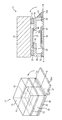
도 1은, 종래의 카메라 모듈의 외관 사시도 및 측면 단면도이다. 보다 상세하게는, 도 1의 좌부(左部)는, 카메라 모듈의 외관 사시도이고, 도 1의 우부(右部)는, 카메라 모듈의 측면 단면도이다. 또한, 도 1의 우부인 측면 단면도는, 도 1의 좌부에서의 외관 사시도에서의 AB에서 도시되는 직선에서의 AB 단면이다.1 is an external perspective view and a side sectional view of a conventional camera module. More specifically, the left portion of FIG. 1 is an external perspective view of the camera module, and the right portion of FIG. 1 is a side sectional view of the camera module. 1 is an AB cross-section in a straight line shown at AB in an external perspective view in the left part of Fig. 1. Fig.
도 1의 카메라 모듈(11)은, 피사체로부터의 입사광의 입사 방향인 도면 중 상부로부터 차례로 렌즈 유닛(31), IRCF(적외선 커트 필터)(32), 프레임(34), 고체 촬상 소자(41)가 마련된 리지드 플렉시블 기판(36)으로 구성되어 있다.The
렌즈 유닛(31)과 고체 촬상 소자(41)는 동축상에 마련되어 있고, 프레임(34)에는, 고체 촬상 소자(41)에 대응하는 위치에 개구부(34a)가 마련되어 있고, 개구부(34a)를 막도록 IRCF(32)가 마련되어 있다.The
이와 같은 구성에 의해, 렌즈 유닛(31)을 투과한 광이, IRCF(32)를 투과하여, 고체 촬상 소자(41)에 입사하는 구성으로 되어 있다.With such a configuration, the light transmitted through the
보다 상세하게는, 도 1의 카메라 모듈(11)은, 이미지 센서(41)가 마련된 리지드 플렉시블 기판(36)상에, IRCF(32)를 포함하는 프레임(34)이 재치되고, 그 접착면에 열경화성의 프레임 수지(35)가 도포되어 접착되어 있다.More specifically, in the
프레임(34)에는, 이미지 센서(41)에 대응하는 위치에 사각형상의 개구부(34a)가 마련되어 있고, 개구부(34a)의 사각형상의 1변을 제외한 상태로 둘러싸도록 접착제(40)가 도포되고, IRCF(32)가 접착됨에 의해, 통기구멍(39)이 형성된다.The
이와 같은 구성에 의해, 프레임 수지(35)를 열에 의해 경화시켜서, 프레임(34)과 리지드 플렉시블 기판(36)을 접착시킬 때, 가열에 의해 팽창한 공기가 통기구멍(39)으로부터 배출된다.With this configuration, when the
또한, 프레임(34)과 리지드 플렉시블 기판(36)이 프레임 수지(35)에 의해 접착된 후, 통기구멍(39)을 막도록 후밀봉(後封止) 수지(38)가 도포된다.Further, after the
이 후밀봉 수지(38)에 의해 통기구멍(39)이 막힘으로써, 통기구멍(39)을 통하여 더스트가 들어감이 방지되기 때문에 고체 촬상 소자(41)상의 오염의 부착에 의해 생기는 흑점의 발생을 억제하는 것이 가능해진다.The ventilation hole 39 is blocked by the sealing
또한, 그 후, 프레임(34)의 윗면의 단부(端部)에 렌즈 유닛 체결 수지(33)를 도포하고, 그 위에 렌즈 유닛(31)을 재치하여 접착한다.Thereafter, the lens
그 후, 도면 중 우하부(右下部)로 늘어나 있는 FPC(Flexible Print Circuit) 인출부(36a)의 근원으로서, 프레임(34)의 리지드 플렉시블 기판(36)과의 접합면에 따라 보강 수지(37)가 도포된다.Thereafter, as a root of the FPC (Flexible Printed Circuit) lead-out
이와 같이 보강 수지(37)가 도포됨에 의해, FPC 인출부(36a)를 도면 중의 화살표 방향이나 화살표와 반대 방향으로 되접음(折り返し)을, 모듈을 파괴하는 일 없이 실현하는 것이 가능해진다.As described above, by applying the reinforcing
이상의 공정에 의해 종래의 카메라 모듈(11)이 제조된다.The
그렇지만, 이 공정에서는, 일단, 통기구멍(39)을 막기 위한 후밀봉 수지(38)를 도포하는 공정이 별도로 필요해진다.However, in this step, a step of applying the
<제1의 실시의 형태>≪ First Embodiment >
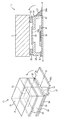
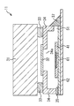
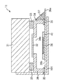
도 2는, 본 기술을 적용한 카메라 모듈의 제1의 실시의 형태의 외관 사시도, 및 외관 사시도에서의 AB 단면이 되는 측면 단면도이다. 또한, 도 2의 카메라 모듈에서, 도 1의 카메라 모듈에서의 구성과, 동일한 기능을 구비한 구성에 관해서는, 동일한 명칭, 및 동일한 부호를 붙이고 있고, 그 설명은 적절히 생략하는 것으로 한다.Fig. 2 is an external perspective view of the first embodiment of the camera module to which the present technology is applied, and Fig. 2 is a side sectional view showing the AB cross section in the external perspective view. In the camera module of Fig. 2, the configuration of the camera module of Fig. 1 and the configuration having the same function are denoted by the same names and the same reference numerals, and a description thereof will be omitted as appropriate.
즉, 도 2의 카메라 모듈(11)에서, 도 1의 카메라 모듈(11)과 다른 점은, 윗면에서 본 때 사각형상의 프레임(34)의 4변 중의 1변이 되는 FPC 인출부(36a)와 접하는 일부분에 관해, 접착제인 프레임 수지(35)가 도포되지 않은 구성으로 되고, 또한, 프레임(34)의 개구부와 IRCF(32)가 통기구멍(39)과 같은 간극이 없는, 4변이 완전히 당접(當接)한 상태로 접합되어 있는 점이다.The
이와 같은 구성에 의해, 프레임(34)과 리지드 플렉시블 기판(36)이 당접할 때, 프레임(34)의 4변 중의 1변이 되는 FPC 인출부(36a)와 접하는 변의 일부에 관해, 프레임(34)과 리지드 플렉시블 기판(36)과의 사이에 슬릿형상의 통기구멍(51)이 형성된다.With this configuration, when the
결과로서, 프레임(34)과 리지드 플렉시블 기판(36)을 접합하기 위해, 상호의 당접 부분의 프레임 수지(35)가 경화하도록 가열되어도, 프레임(34)과 리지드 플렉시블 기판(36)과의 당접 부분의 일부에 생기는 슬릿형상의 통기구멍(51)으로부터 팽창한 기체를 배출할 수 있다.As a result, in order to bond the
또한, 프레임(34)과 리지드 플렉시블 기판(36)을 프레임 수지(35)를 경화시켜서 접합한 후, 통기구멍(51)을 막도록 보강 수지(37)가 도포되도록 함으로써, 통기구멍(51)을 막기 위한 후밀봉 수지(38)를 도포할 뿐이라는 공정을 생략하는 것이 가능해진다.The reinforcing
<도 2의 카메라 모듈의 제조 공정><Manufacturing Process of Camera Module of FIG. 2>
다음에, 도 3의 플로우 차트를 참조하여, 도 2의 카메라 모듈의 제조 공정에 관해 설명한다.Next, the manufacturing process of the camera module of Fig. 2 will be described with reference to the flowchart of Fig.
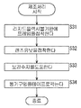
스텝 S11에서, 도 4의 최상부 및 위로부터 2단째에서 도시되는 바와 같이, 개구부(34a)를 완전히 막도록 IRCF(32)가 접속되어 있는 프레임(34)을, 리지드 플렉시블 기판(36)상에 재치하여, 당접 부위로서, FPC 인출부(36a)와 접하는 변의 일부를 제외한 범위에 프레임 수지(35)를 도포하여 접착한다.The
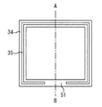
보다 상세하게는, 도 5에서 도시되는 바와 같이, 프레임(34)의 도 4에서의 하방향에서 본 경우, 단부(端部)로서, FPC 인출부(36a)와 접하는 변의 일부 이외의 범위에 프레임 수지(35)를 도포한 다음, 도 4의 2단째에서 도시되는 바와 같이, 프레임(34)을 리지드 플렉시블 기판(36)에 접착시키다. 또한, 프레임 수지(35)는, 도 5에서 도시되는 바와 같이, 사각형상의 프레임(34)의 리지드 플렉시블 기판(36)과의 당접 부위로서, FPC 인출부(36a)와 접하는 변에 관해서는, 1변의 길이보다도 짧은 범위의 중앙 부근에 도포하고, 그 이외의 변에 관해서는 전 범위를 도포하도록 하여도 좋고, 대응하는 리지드 플렉시블 기판(36)상의 위치에 도포하도록 하여도 좋다.More specifically, as shown in Fig. 5, as viewed from the downward direction in Fig. 4 of the
이와 같이 프레임 수지(35)가 도포됨에 의해, 프레임 수지(35)를 경화시킬 때에 가열함으로써, 프레임(34)과 리지드 플렉시블 기판(36) 사이의 공간의 기체가 팽창하여도, 슬릿형상으로 형성되는 통기구멍(51)으로부터 배출하는 것이 가능해진다. 이 프레임 수지(35)는, 열경화 수지뿐만 아니라, 자외선(UV)을 조사한 후, 가열함에 의해 경화하는 UV+열경화 수지라도 좋다.By applying the
스텝 S12에서, 도 4의 위로부터 3단째에서 도시되는 바와 같이, 렌즈 유닛(31)과 프레임(34)이 렌즈 유닛 체결 수지(33)에 의해 접착된다.In step S12, the
스텝 S13에서, 도 4의 최하단에서 도시되는 바와 같이, 통기구멍(51)이 형성되어 있는, FPC 인출부(36a)와 접하는 부위에 보강 수지(37)를 도포하여, 가열함에 의해 경화시킴으로써 제조를 완료시킨다.The reinforcing
또한, 보강 수지(37)는, 열경화 수지뿐만 아니라, 자외선(UV)을 조사하여 경화하는 UV 수지, 자외선(UV)을 조사한 후, 가열에 의해 경화하는 UV+열경화 수지라도 좋다. 또한, 보강 수지(37)는, 탄성률이 25℃에서 100㎫ 내지 10000㎫ 정도가 되는, 흑색 등의 차광 수지로 함에 의해, 통기구멍(51)을 통하여 입사하는 광에 의한 플레어를 억제하는 것이 가능해진다.The reinforcing
원래 보강 수지(37)는, 리지드 플렉시블 기판(36)과, FPC 인출부(36a)와의 접합부, 또는, 리지드 플렉시블 기판(36)과, 프레임(34)과의 접합부를 보강하는 것을 목적으로 하는 것이다. 따라서 종래로부터 보강 수지(37)가 도포됨으로써 보강되는 부위에 의해, FPC 인출부(36a)를 도 2 중의 화살표 방향 또는 역방향으로 절곡한다는 작업을 하여도, FPC부가 파단되거나, 타부품과의 접착을 파괴하는 일이 없도록 하는 것이 가능해진다. 또한, 보강 수지(37)는, 원래 통기구멍(51)이 마련된 부위에 도포되는 것이기 때문에, 보강 수지(37)가 도포되는 공정은, 종래의 카메라 모듈(11)의 제조 공정에도 포함되는 공정이다. 이 때문에, 보강 수지(37)가 도포되는 공정에, 통기구멍(51)을 막는 공정을 포함시킬 수 있기 때문에, 통기구멍(51)을 막기 위할 뿐의 공정을 생략할 수 있고, 제조 공정의 전체에서의 공수를 저감시키는 것이 가능해진다.The original reinforcing
<제1의 변형례>≪ First Modification Example &
이상에서는, 리지드 플렉시블 기판(36)과 프레임(34)과의 접착 부위로서, 또한, 보강 수지(37)를 도포하지 않는 1변의, 1변보다도 짧은 범위에 프레임 수지(35)를 도포하지 않는 구성으로 하고, 보강 수지(37)를 나중에 도포하는 예에 관해 설명하여 왔지만, 최종적으로 보강 수지(37)가 도포되는 부위의 일부에 프레임 수지(35)를 도포하지 않도록 하면, 다른 구성이라도 좋다.The
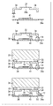
예를 들면, 도 6에서 도시되는 바와 같이, 기판(61)상에 고체 촬상 소자가 마련되어 있고, 또한, 그 아래에 플렉시블판(板)(62)이 마련되는 경우, 프레임(34)과 기판(61)과의 접착 부위 중, 플렉시블판(62)이 인출되는 부위이고, 보강 수지(37)가 도포되는 부위의 일부에 프레임 수지(35)를 도포하지 않도록 하여 프레임(34)과 기판(61)을 접착하도록 하여도 좋다. 즉, 도 6에서는 실질적으로, 리지드 플렉시블 기판(36)을, 기판(61)과 플렉시블판(62)을 사용하여 구성한 것이라고도 생각된다. 이와 같은 구성으로 함으로써, 도 6에서 도시되는 바와 같이, 통기구멍(51)이 형성되기 때문에, 프레임(34)과 기판(61)이 접착될 때에, 프레임 수지(35)를 경화시키기 위해 가열될 때에는, 팽창한 기체가 통기구멍(51)으로부터 배출됨과 함께, 접착된 후에, 보강 수지(37)가 도포됨으로써, 통기구멍(51)이 막히기 때문에, 통기구멍(51)을 막을 뿐의 공정을 생략하면서, 통기구멍(51)을 막는 것이 가능해지고, 결과로서, 고체 촬상 소자(41)에의 부착물의 침입을 막을 수 있고, 흑점의 발생을 억제하는 것이 가능해진다.6, when the solid-state image pickup device is provided on the
<제2의 변형례>≪ Second Modification Example &
이상에서는, 프레임(34)과 리지드 플렉시블 기판(36)을 접속함에 있어서 프레임 수지(35)를 사용하는 예에 관해 설명하여 왔지만, 프레임(34)과 리지드 플렉시블 기판(36)과의 사이에 몰드를 이용하도록 하여도 좋다. 이 경우, 도 7에서 도시되는 바와 같이, 몰드(71) 중, FPC 인출부(36a)에 대응하는 위치로서, 후단의 처리에서, 보강 수지(37)가 도포되지 않는 부위에 대응하는 일부에 프레임과 접하지 않는 부위를 마련하도록 하다, 또는 프레임 수지(35)를 도포하지 않음으로써, 통기구멍(51)이 형성되도록 한다.Although the
결과로서, 도 7에서 도시되는 구성에 의해, 도 2, 도 6에서 도시되는 카메라 모듈(11)에서의 경우와 같은 효과를 이루는 것이 가능해진다.As a result, with the configuration shown in Fig. 7, the same effect as in the case of the
<제3의 변형례>≪ Third Modification Example &
이상에서는, 통기구멍(51)이 1개소 마련되는 예에 관해 설명하여 왔지만, 프레임(34)과 리지드 플렉시블 기판(36)이 접착되는 면의 일부로서, 후단의 공정에서의 보강 수지(37)가 도포되는 범위라면, 통기구멍(51)은 복수개소에 구성되도록 하여도 좋다.As described above, the reinforcing
즉, 예를 들면, 도 8에서 도시되는 바와 같이, 프레임(34)과 리지드 플렉시블 기판(36)을 접착할 때에, 프레임 수지(35)가 도포되지 않는 부위를 2개소 마련하도록 함으로써, 통기구멍(51-1, 51-2)이 마련되도록 하여도 좋고, 또한, 이 이상의 수의 통기구멍(51)이 마련되도록 하여도 좋다.8, when the
결과로서, 도 8에서 도시되는 구성에 의해, 도 2, 도 6, 도 7에서 도시되는 카메라 모듈(11)에서의 경우와 같은 효과를 이루는 것이 가능해진다.As a result, with the configuration shown in Fig. 8, the same effect as in the case of the
<제2의 실시의 형태>≪ Second Embodiment >
이상에서는, 프레임(34)과 리지드 플렉시블 기판(36)이 접착되는 면의 일부로서, 후단의 처리에 의해, 보강 수지(37)가 도포되는 영역의 일부에, 프레임 수지(35)를 도포하지 않는 영역을 마련함으로써, 프레임(34)과 리지드 플렉시블 기판(36)과의 접착 부위에 통기구멍(51)을 형성시키도록 한 예에 관해 설명하여 왔다.The
그렇지만, 프레임 수지(35)를 경화시킬 때에 필요하게 되는 통기구멍(51)을 어느 하나의 부위에 마련하도록 하여, 프레임(34)과 리지드 플렉시블 기판(36)과의 접착이 완료된 후, 접착 테이프에 의해 통기구멍(51)을 막도록 하여도 좋다.However, after the bonding between the
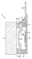
도 9는, 프레임 수지(35)를 경화시킬 때에 필요하게 되는 통기구멍(51)을 어는 한 부위에 마련하도록 하여, 프레임(34)과 리지드 플렉시블 기판(36)과의 접착이 완료된 후, 접착 테이프에 의해 막도록 한 카메라 모듈(11)의 구성례를 도시하고 있다. 또한, 도 9에서, 도 2의 카메라 모듈에서의 구성과 동일한 기능을 구비한 구성에 관해서는, 동일한 명칭 및 동일한 부호를 붙이고 있고, 그 설명은 적절히 생략하는 것으로 한다.9 shows a state in which the
즉, 도 9의 카메라 모듈(11)에서, 도 2의 카메라 모듈(11)과 다른 점은, 프레임 수지(35)를 도포하지 않은 부위를, 프레임(34)의 단부 중, 보강 수지(37)가 도포되는 변과 대향하는 변의 일부에 마련함으로써, 통기구멍(51)을 형성함과 함께, 또한, 그 부위를 점착 테이프(101)에 의해 피복하고 있는 점이다.The
이와 같은 구성에 의해, 프레임(34)과 리지드 플렉시블 기판(36)을 접합하기 위해, 상호의 당접 부분의 프레임 수지(35)가 경화하도록 가열되어도, 프레임(34)과 리지드 플렉시블 기판(36)과의 당접 부분의 일부에 생기는 슬릿형상의 통기구멍(51)으로부터 팽창한 기체를 배출할 수 있다.With this structure, even if the
또한, 프레임(34)과 리지드 플렉시블 기판(36)을 프레임 수지(35)를 경화시켜서 접합한 후, 통기구멍(51)을 막도록 점착 테이프(101)가 부착됨으로써, 점착 테이프(101)와 프레임(34) 및 리지드 플렉시블 기판(36)과의 사이에 기밀성을 깨는 간격이 생겨도, 점착 테이프(101)의 점착성에 의해 더스트를 부착시킴으로써, 프레임(34)과 리지드 플렉시블 기판(36) 사이의 공간으로의 더스트의 침입을 방지하는 것이 가능해지고, 흑점의 발생을 억제하는 것이 가능해진다.The
또한, 도 9의 예에서는, 프레임 수지(35)를 도포하지 않음으로써 형성된 통기구멍(51)을, 보강 수지(37)가 도포되는 변에 대해 대향하는 변의 일부로 하는 예에 관해 설명하여 왔지만, 후단의 처리에서 보강 수지(37) 등이 도포되지 않는 변의 일부에 의해 형성된 통기구멍(51)에 관해서는, 점착 테이프(101)를 부착하는 부위라면, 그 밖의 부위에 형성하도록 하여도 좋다.In the example of Fig. 9, the
<도 9의 카메라 모듈의 제조 공정><Manufacturing Process of Camera Module of FIG. 9>
다음에, 도 10의 플로우 차트를 참조하여, 도 9의 카메라 모듈의 제조 공정에 관해 설명한다.Next, the manufacturing process of the camera module of Fig. 9 will be described with reference to the flowchart of Fig.
스텝 S31에서, 도 11의 최상단 및 위로부터 2단째에서 도시되는 바와 같이, 개구부(34a)를 완전히 막도록 IRCF(32)가 접속되어 있는 프레임(34)을, 리지드 플렉시블 기판(36)상에 재치하여, 당접 부위로서, FPC 인출부(36a)와 접하는 변과 대향하는 변의 일부를 제외한 범위에 프레임 수지(35)를 도포하여 접착한다.The
이와 같이 프레임 수지(35)가 도포됨에 의해, 프레임 수지(35)를 경화시킬 때에 가열함으로써, 프레임(34)과 리지드 플렉시블 기판(36) 사이의 공간의 기체가 팽창하여도, 슬릿형상의 통기구멍(51)으로부터 배출하는 것이 가능해진다. 이 프레임 수지(35)는, 열경화 수지뿐만 아니라, 자외선(UV)을 조사한 후, 가열함에 의해 경화하는 UV+열경화 수지라도 좋다. 또한, 프레임 수지(35)는, 도 5에서 도시되는 바와 같이, 사각형상의 프레임(34)의 리지드 플렉시블 기판(36)과의 당접 부위로서, FPC 인출부(36a)와 접하는 변에 관해서는, 1변의 길이보다도 짧은 범위의 중앙 부근에 도포하고, 그 이외의 변에 관해서는 전 범위를 도포하도록 하여도 좋고, 대응하는 리지드 플렉시블 기판(36)상의 위치에 도포하도록 하여도 좋다.Even when the gas in the space between the
스텝 S32에서, 도 11의 위로부터 3단째에서 도시되는 바와 같이, 렌즈 유닛(31)과 프레임(34)이 렌즈 유닛 체결 수지(33)에 의해 접착된다.In step S32, the
스텝 S33에서, 도 11의 위로부터 3단째에서 도시되는 바와 같이, FPC 인출부(36a)와 접하는 부위에 보강 수지(37)를 도포한다.In step S33, a reinforcing
또한, 보강 수지(37)는, UV 경화 수지, 열경화 수지뿐만 아니라, 자외선(UV)을 조사한 후, 가열에 의해 경화하는 UV+열경화 수지라도 좋다. 또한, 보강 수지(37)는, 탄성률이 100㎫ 내지 10000㎫ 정도가 되는, 흑색 등의 차광 수지로 함에 의해, 통기구멍(51)을 통하여 입사하는 광에 의한 플레어를 억제하는 것이 가능해진다.The reinforcing
스텝 S34에 있어서, 도 11의 최하단에서 도시되는 바와 같이, 통기구멍(51)을 막도록, 점착 테이프(101)를 부착하여, 제조를 완료시킨다.In step S34, the
점착 테이프(101)는, 도 11의 최하단에서 도시되는 위치에 부착되는 것이기 때문에, 점착 테이프(101)가 부착되는 공정은, 원래 존재하는 공정이다. 그 때문에, 원래 부착되는 점착 테이프(101)에 의해, 통기구멍(51)이 막히는 것이 되기 때문에, 통기구멍(51)을 막기 위한 공정을 생략할 수 있고, 결과로서, 제조 공정의 전체에서의 공수를 저감시키는 것이 가능해진다.Since the
또한, 이와 같이 점착 테이프(101)가 통기구멍(51)을 막도록 부착되기 때문에, 통기구멍(51)을 직접 통과하는 더스트 등의 침입을 방지하는 것이 가능해진다. 또한, 점착 테이프(101)를 부착함에 있어서, 프레임(34) 및 리지드 플렉시블 기판(36)과의 접착면에는 미소한 간극이 발생한 가능성이 있지만, 점착 테이프(101)의 점착성에 의해 더스트를 포집할 수 있기 때문에, 프레임(34)과 리지드 플렉시블 기판(36) 사이의 공간으로의 더스트의 침입을 방지할 수 있고, 흑점의 발생을 억제하는 것이 가능해진다.Further, since the
또한, 통기구멍(51)은, 단독의 1개소로 하도록 하여도 좋고, 상술한 도 8에서의 예와 마찬가지로 복수로 마련하도록 하여도 좋다. 이 경우, 후단에서, 점착 테이프(101)가 부착되는 부위라면, 위치는 어느 것이라도 좋다.The ventilation holes 51 may be provided at a single position or may be provided in plural as in the example shown in Fig. In this case, any position may be used as far as the
<제4의 변형례>≪ Fourth Modification Example &
이상에서는, 리지드 플렉시블 기판(36)과 프레임(34)과의 접착 부위로서, 또한, 보강 수지(37)를 도포하지 않은 부위의 일부에 프레임 수지(35)를 도포하지 않는 구성으로 하고, 점착 테이프(101)를 나중에 부착하는 예에 관해 설명하여 왔지만, 최종적으로 프레임 수지(35)를 도포하지 않은 부위에 점착 테이프(101)를 후단의 공정에서 부착하도록 하면, 다른 구성이라도 좋다.The
예를 들면, 도 12에서 도시되는 바와 같이, 기판(61)상에 고체 촬상 소자(41)가 마련되어 있고, 또한, 그 아래에 플렉시블판(62)이 마련되는 경우, 프레임(34)과 기판(61)과의 접착 부위 중, 보강 수지(37)가 도포되지 않는 부위의 일부에 프레임 수지(35)를 도포하지 않도록 하여 프레임(34)과 기판(61)을 접착하도록 하여도 좋다. 즉, 도 12에서는 실질적으로, 리지드 플렉시블 기판(36)을, 기판(61)과 플렉시블판(62)을 이용하여 구성한 것이라고도 생각된다. 이와 같은 구성으로 함으로써, 도 12에서 도시되는 바와 같이, 통기구멍(51)이 형성되기 때문에, 프레임(34)과 기판(61)이 접착될 때에, 프레임 수지(35)를 경화시키기 위해 가열될 때에는, 팽창한 기체가 통기구멍(51)으로부터 배출됨과 함께, 접착된 후에, 점착 테이프(101)가 부착됨으로써 통기구멍(51)이 막히기 때문에, 통기구멍(51)으로부터의 더스트의 침입을 방지하는 것이 가능해지고, 결과로서, 고체 촬상 소자(41)에의 부착물의 침입을 막을 수 있고, 흑점의 발생을 억제하는 것이 가능해진다.12, when the solid-state
<제5의 변형례>≪ Fifth Modification Example &
이상에서는, 프레임(34)과 리지드 플렉시블 기판(36)을 접속함에 있어서 프레임 수지(35)를 사용하는 예에 관해 설명하여 왔지만, 프레임 수지(35) 대신에 몰드(71)를 이용하도록 하여도 좋다. 이 경우, 도 13에서 도시되는 바와 같이, 몰드(71) 중, 보강 수지(37)가 도포되지 않는 부위의 일부가 프레임(34)과 접하지 않는 부위를 마련하도록 함으로써, 통기구멍(51)이 형성되도록 한다.The
결과로서, 도 13에서 도시되는 구성에 의해, 도 9, 도 12에서 도시되는 카메라 모듈에서의 경우와 같은 효과를 이루는 것이 가능해진다.As a result, with the configuration shown in Fig. 13, the same effect as in the case of the camera module shown in Figs. 9 and 12 can be achieved.
<제6의 변형례>≪ Sixth Modification Example &
이상에서는, 프레임(34)과 리지드 플렉시블 기판(36)과의 접합부위의 일부에 프레임 수지(35)를 도포하지 않도록 함으로써, 통기구멍(51)을 형성하는 예에 관해 설명하여 왔지만, 후단의 처리로 점착 테이프(101)가 부착된 부위라면, 어느 곳에 통기구멍(51)이 형성되어도 좋다.In the above description, the example in which the
예를 들면, 도 14에서 도시되는 바와 같이, 리지드 플렉시블 기판(36)의 일부에 리지드 플렉시블 기판(36)을 관통하는 구멍부(36b)를 형성하고, 이것을 통기구멍(51)에 대신하는 통기구멍으로 함으로써, 프레임 수지(35)를 경화할 때에는, 팽창한 기체를 배출하는 것이 가능해진다. 또한, 프레임 수지(35)가 경화한 후에, 구멍부(31b)에 의해 형성된 통기구멍을 막도록, 점착 테이프(101)를 부착하도록 함으로써, 프레임(34)과 리지드 플렉시블 기판(36) 사이의 공간으로의 더스트의 침입을 방지하는 것이 가능해지고, 결과로서, 고체 촬상 소자(41)에서 흑점의 발생을 억제하는 것이 가능해진다. 또한, 이 경우에도, 후단의 처리에 의해 점착 테이프(101)가 부착되는 위치라면, 구멍부(36b)는 복수로 마련되도록 하여도 좋다. 또한, 구멍부(36b)에 대신하여, 스루홀을 마련하도록 하여도 좋다.For example, as shown in Fig. 14, a
<제3의 실시의 형태>≪ Third Embodiment >
이상에서는, 프레임(34)을 프레임 수지(35)에 의해 리지드 플렉시블 기판(36)과 접착하고, 또한, 프레임(34)과 렌즈 유닛(31)을 렌즈 유닛 체결 수지(33)에 의해 접착함으로써, 렌즈 유닛(31)을 리지드 플렉시블 기판(36)에 고정하는 구성례에 관해 설명하여 왔다. 그렇지만, 렌즈 유닛(31)과 프레임(34)이 일체가 된 구성의 렌즈 유닛(31)에 의해, 렌즈 유닛(31)과 리지드 플렉시블 기판(36)을 직접 접착하도록 하여도 좋다.The
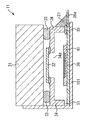
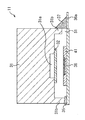
도 15는, 렌즈 유닛(31)과 리지드 플렉시블 기판(36)을 직접 접착하도록 한 카메라 모듈(11)의 구성례를 도시하고 있다. 또한, 도 15의 카메라 모듈에서, 도 2의 카메라 모듈에서의 구성과, 동일한 기능을 구비한 구성에 관해서는, 동일한 명칭, 및 동일한 부호를 붙이고 있고, 그 설명은 적절히 생략하는 것으로 한다.Fig. 15 shows an example of the configuration of the
즉, 도 15의 카메라 모듈(11)에서는, 프레임(34)의 구성에 상당하는 부위를 갖는 렌즈 유닛(31)을 구비하고 있다.That is, the
보다 상세하게는, 도 15의 렌즈 유닛(31)은, 도면 중 하부의 리지드 플렉시블 기판(36)과 대향하는 부위에, 프레임(34)의 구성에 상당하는 프레임부(31b)를 구비하고 있고, 프레임 수지(35)에 의해 리지드 플렉시블 기판(36)과 접착되어 있다. 즉, 프레임부(31b)는, 렌즈 유닛(31)과 일체의 구성으로 되어 있다.More specifically, the
또한, 렌즈 유닛(31)에는, 도면 중의 하부이고, 이미지 센서(41)와 대향하는 위치에, 프레임(34)에서의 개구부(34a)에 상당하는 개구부(31a)가 마련되어 있고, 개구부(31a)를 막도록 IRCF(32)가 마련되어 있다.The
프레임부(31b)의 4변 중의 1변이 되는 FPC 인출부(36a)와 접하는 변의 일부에 관해, 프레임부(31a)와 리지드 플렉시블 기판(36)과의 사이에 슬릿형상의 통기구멍(51)이 형성되어 있다.A slit-shaped
결과로서, 렌즈 유닛(31)의 프레임부(31b)와 리지드 플렉시블 기판(36)을 접합하기 위해, 상호의 당접 부분의 프레임 수지(35)가 경화하도록 가열되어도, 프레임부(31b)와 리지드 플렉시블 기판(36)과의 당접 부분의 일부에 생기는 슬릿형상의 통기구멍(51)으로부터 팽창한 기체를 배출할 수 있다.As a result, in order to bond the
또한, 렌즈 유닛(31)의 프레임부(31b)와 리지드 플렉시블 기판(36)을 프레임 수지(35)를 경화시켜서 접합한 후, 통기구멍(51)을 막도록 보강 수지(37)가 도포되도록 함으로써, 통기구멍(51)을 막기 위한 후밀봉 수지(38)를 도포할 뿐이라는 공정을 생략하는 것이 가능해진다.The reinforcing
또한, 프레임(34)에 상당하는 프레임부(31b)를 구비한 렌즈 유닛(11)을 이용하여, 상술한 제1의 변형례 내지 제3의 변형례에 대응하는 구성으로 하도록 하여 도, 같은 효과를 이룬다.Even if the
<제4의 실시의 형태>≪ Fourth Embodiment >
이상에서는, 프레임(34)이 일체가 된 구성의 렌즈 유닛(31)을, 리지드 플렉시블 기판(36)에 직접 접착하도록 한 예에 관해 설명하여 왔지만, 또한, 프레임(34)이 일체가 된 렌즈 유닛(31)과 리지드 플렉시블 기판(36)과의 접착을 완료한 후, 그 프레임부(31a)에 마련된 통기구멍(51)을 접착 테이프에 의해 막도록 하여도 좋다.In the above description, the
도 16은, 프레임(34)이 일체가 된 렌즈 유닛(31)과, 리지드 플렉시블 기판(36)을 접속하는 프레임 수지(35)를 경화시킬 때에, 통기구멍(51)을 접속부위의 어느 하나에 마련하도록 하여, 렌즈 유닛(31)과 리지드 플렉시블 기판(36)과의 접착이 완료된 후, 통기구멍(51)을 접착 테이프에 의해 막도록 한 카메라 모듈(11)의 구성례를 도시하고 있다. 또한, 도 16에서, 도 9의 카메라 모듈에서의 구성과 동일한 기능을 구비한 구성에 관해서는, 동일한 명칭 및 동일한 부호를 붙이고 있고, 그 설명은 적절히 생략하는 것으로 한다.16 shows a state in which when the
즉, 도 16의 카메라 모듈(11)은, 도 9의 카메라 모듈(11)과 마찬가지로 프레임 수지(35)를 도포하지 않은 부위를, 프레임부(31b)의 단부 중, 보강 수지(37)가 도포되는 변과 대향하는 변의 일부에 마련함으로써, 통기구멍(51)을 형성함과 함께, 또한, 그 부위를 점착 테이프(101)에 의해 피복하고 있다.That is, the
이와 같은 구성에 의해, 렌즈 유닛(31)과 리지드 플렉시블 기판(36)을 접합하기 위해, 상호의 당접 부분의 프레임 수지(35)가 경화하도록 가열되어도, 프레임(34)과 리지드 플렉시블 기판(36)과의 당접 부분의 일부에 생기는 슬릿형상의 통기구멍(51)으로부터 팽창한 기체를 배출할 수 있다.With this configuration, even when the
또한, 렌즈 유닛(31)과 리지드 플렉시블 기판(36)을 프레임 수지(35)를 경화시켜서 접합한 후, 통기구멍(51)을 막도록 점착 테이프(101)가 부착됨으로써, 점착 테이프(101)와 프레임부(31b) 및 리지드 플렉시블 기판(36)과의 사이에 기밀성을 깨는 간격이 있어서도, 점착 테이프(101)의 점착성에 의해 더스트를 부착시킴으로써, 프레임부(31b)와 리지드 플렉시블 기판(36) 사이의 공간으로의 더스트의 침입을 방지하는 것이 가능해지고, 흑점의 발생을 억제하는 것이 가능해진다.The
또한, 도 16의 예에서는, 프레임 수지(35)를 도포하지 않음으로써 형성되는 통기구멍(51)을, 보강 수지(37)가 도포되는 변에 대해 대향하는 변의 일부로 하는 예에 관해 설명하여 왔지만, 후단의 처리로 보강 수지(37) 등이 도포되지 않는 변의 일부에 의해 형성된 통기구멍(51)에 관해서는, 점착 테이프(101)를 부착하는 부위라면, 그 밖의 부위에 형성하도록 하여도 좋다.In the example shown in Fig. 16, the
또한, 프레임(34)에 상당하는 프레임부(31b)를 구비한 렌즈 유닛(11)을 이용하여, 상술한 제4의 변형례 내지 제6의 변형례에 대응하는 구성으로 하도록 하여 도, 같은 효과를 이룬다.Even if the
<전자 기기에의 적용례><Application example to electronic device>
상술한 카메라 모듈은, 예를 들면, 디지털 스틸 카메라나 디지털 비디오 카메라 등의 촬상 장치, 촬상 기능을 구비한 휴대 전화기, 또는, 촬상 기능을 구비한 다른 기기라는 각종의 전자 기기에 적용할 수 있다.The camera module described above can be applied to various electronic devices such as an imaging device such as a digital still camera or a digital video camera, a mobile phone having an imaging function, or another device having an imaging function.
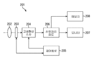
도 17은, 본 기술을 적용한 전자 기기로서의 촬상 장치의 구성례를 도시하는 블록도이다.17 is a block diagram showing an example of the configuration of an image pickup apparatus as an electronic apparatus to which the present technique is applied.
도 17에 도시되는 촬상 장치(201)는, 광학계(202), 셔터 장치(203), 고체 촬상 소자(204), 구동 회로(205), 신호 처리 회로(206), 모니터(207), 및 메모리(208)를 구비하여 구성되고, 정지화상 및 동화상을 촬상 가능하다.17 includes an
광학계(202)는, 1장 또는 복수장의 렌즈를 갖고서 구성되고, 피사체로부터의 광(입사광)을 고체 촬상 소자(204)에 유도하여, 고체 촬상 소자(204)의 수광면에 결상시킨다.The
셔터 장치(203)는, 광학계(202) 및 고체 촬상 소자(204)의 사이에 배치되고, 구동 회로(205)의 제어에 따라, 고체 촬상 소자(204)에의 광조사 기간 및 차광 기간을 제어한다.The
고체 촬상 소자(204)는, 상술한 고체 촬상 소자(1), 또는, 고체 촬상 소자(1)에 의해 구성된다. 고체 촬상 소자(204)는, 광학계(202) 및 셔터 장치(203)를 통하여 수광면에 결상되는 광에 응하여, 일정 기간, 신호 전하를 축적한다. 고체 촬상 소자(204)에 축적된 신호 전하는, 구동 회로(205)로부터 공급되는 구동 신호(타이밍 신호)에 따라 전송된다.The solid-
구동 회로(205)는, 고체 촬상 소자(204)의 전송 동작, 및, 셔터 장치(203)의 셔터 동작을 제어하는 구동 신호를 출력하고, 고체 촬상 소자(204) 및 셔터 장치(203)를 구동한다.The drive circuit 205 outputs a drive signal for controlling the transfer operation of the solid state
신호 처리 회로(206)는, 고체 촬상 소자(204)로부터 출력된 신호 전하에 대해 각종의 신호 처리를 시행한다. 신호 처리 회로(206)가 신호 처리를 시행함에 의해 얻어진 화상(화상 데이터)은, 모니터(207)에 공급되어 표시되거나, 메모리(208)에 공급되어 기억(기록)되거나 한다.The
이와 같이 구성되어 있는 촬상 장치(201)에서도, 상술한 카메라 모듈(11)을 적용함에 의해, 제조 공정에서의 공수를 저감시킴과 함께, 촬상 소자에의 오염의 부착을 방지시키는 것이 가능해진다.In the
또한, 본 기술은, 이하와 같은 구성도 취할 수 있다.The present technology can also take the following configuration.
(1) 렌즈 유닛과,(1) a lens unit,
고체 촬상 소자를 탑재하고, FPC(Flexible Print Circuit) 인출부가 접합된 리지드 플렉시블 기판과,A rigid flexible substrate on which a solid-state image pickup device is mounted and on which an FPC (Flexible Print Circuit) lead-out portion is joined,
상기 렌즈 유닛과, 상기 리지드 플렉시블 기판을 접속하고, 개구부를 갖는 프레임을 포함하고,And a frame which connects the lens unit and the rigid flexible substrate and has an opening,
상기 프레임과, 상기 리지드 플렉시블 기판과의, 당접면 중, 상기 FPC 인출부와의 접합부를 포함하는 범위의 일부를 제외하고 도포되는 접착제에 의해 접착되고,The frame and the rigid flexible substrate are adhered by an adhesive that is applied except for a part of the contact surface of the contact surface with the FPC lead portion,
상기 리지드 플렉시블 기판과, 상기 FPC 인출부와의 접합부, 또는, 상기 리지드 플렉시블 기판과, 상기 프레임과의 접합부를 보강하는 보강 수지가, 상기 접착제가 도포되지 않은 일부의 범위를 막도록 도포되는 카메라 모듈.Wherein a reinforcing resin for reinforcing the bonding portion between the rigid flexible substrate and the FPC lead portion or the bonding portion between the rigid flexible substrate and the frame is applied so as to cover a range of a portion not coated with the adhesive, .
(2) 상기 접착제가 도포되지 않은 범위에 의해, 상기 프레임과 상기 리지드 플렉시블 기판 사이의 공간에서의 통기구멍이 형성되는 (1)에 기재된 카메라 모듈.(2) The camera module according to (1), wherein a vent hole is formed in a space between the frame and the rigid flexible substrate by a range in which the adhesive is not applied.
(3) 상기 보강 수지는, 상기 통기구멍을 막도록 도포되는 (2)에 기재된 카메라 모듈.(3) The camera module according to (2), wherein the reinforcing resin is applied to cover the ventilation holes.
(4) 상기 통기구멍은, 사각형상의 상기 프레임의 1변의 길이보다도 짧은 범위인 (2) 또는 (3)에 기재된 카메라 모듈.(4) The camera module according to (2) or (3), wherein the ventilation hole is in a range shorter than the length of one side of the rectangular frame.
(5) 상기 통기구멍은, 복수 개소에 형성되는 (2) 내지 (4)의 어느 하나에 기재된 카메라 모듈.(5) The camera module according to any one of (2) to (4), wherein the ventilation holes are formed at a plurality of locations.
(6) 상기 접착제는, UV(Ultra Violet)의 조사, 및 가열에 의해 경화하는 UV 열경화 수지, 또는, 가열만에 의해 경화하는 열경화 수지인 (1) 내지 (5)의 어느 하나에 기재된 카메라 모듈.(6) The adhesive according to any one of (1) to (5), wherein the adhesive is a UV curable resin which is cured by irradiation with UV (Ultra Violet) and heating, or a thermosetting resin which is cured by heating only. Camera module.
(7) 상기 보강 수지는, UV(Ultra Violet)의 조사로 경화하는 UV 경화 수지, UV 및 가열에 의해 경화하는 UV 열경화 수지, 또는, 가열만에 의해 경화하는 열경화 수지인 (1) 내지 (6)의 어느 하나에 기재된 카메라 모듈.(7) The reinforcing resin may be a UV curable resin which is cured by irradiation with UV (Ultra Violet), a UV curable resin which is cured by UV and heating, or a thermosetting resin which is cured by heating only. (6).
(8) 상기 보강 수지는, 차광 수지인 (1) 내지 (7)의 어느 하나에 기재된 카메라 모듈.(8) The camera module according to any one of (1) to (7), wherein the reinforcing resin is a light shielding resin.
(9) 상기 보강 수지는, 25℃에서, 탄성률이 100㎫ 내지 10000㎫인 (1) 내지 (8)의 어느 하나에 기재된 카메라 모듈.(9) The camera module according to any one of (1) to (8), wherein the reinforcing resin has a modulus of elasticity of 100 MPa to 10,000 MPa at 25 占 폚.
(10) 상기 접착제는, 상기 프레임과, 상기 리지드 플렉시블 기판과의 당접면 중, 상기 프레임상, 또는, 상기 리지드 플렉시블 기판상의 어느 하나에 도포되는 (1) 내지 (9)의 어느 하나에 기재된 카메라 모듈.(10) The adhesive according to any one of (1) to (9), wherein the adhesive is applied to any one of the contact surface between the frame and the rigid flexible substrate, the frame, or the rigid flexible substrate. module.
(11) 상기 리지드 플렉시블 기판은, 고체 촬상 소자를 탑재한 기판과, 인출부를 포함하는 플렉시블판을 포함하는 (1)에 기재된 카메라 모듈.(11) The camera module according to (1), wherein the rigid flexible substrate includes a substrate on which a solid-state imaging device is mounted, and a flexible plate including a lead-out portion.
(12) 상기 리지드 플렉시블 기판과, 상기 프레임과의 사이에, 몰드를 포함하는 (1)에 기재된 카메라 모듈.(12) A camera module according to (1), comprising a mold between the rigid flexible substrate and the frame.
(13) 상기 프레임은, 상기 렌즈 유닛과 일체의 구성인 (1)에 기재된 카메라 모듈.(13) The camera module according to (1), wherein the frame is a unitary structure with the lens unit.
(14) 렌즈 유닛과,(14) a lens unit,
고체 촬상 소자를 탑재하고, FPC(Flexible Print Circuit) 인출부가 접합된 리지드 플렉시블 기판과,A rigid flexible substrate on which a solid-state image pickup device is mounted and on which an FPC (Flexible Print Circuit) lead-out portion is joined,
상기 렌즈 유닛과, 상기 리지드 플렉시블 기판을 접속하고, 개구부를 갖는 프레임을 포함하는 카메라 모듈의 제조 방법에 있어서,A method of manufacturing a camera module including a frame having an opening and connecting the lens unit to the rigid flexible substrate,
상기 프레임과, 상기 리지드 플렉시블 기판과의, 당접면 중, 상기 FPC 인출부와의 접합부를 포함하는 범위의 일부를 제외하고 도포되는 접착제에 의해 접착한 후,After bonding the frame and the rigid flexible substrate with an adhesive applied to the contact face except a part of the range including the bonding portion with the FPC lead portion,
상기 리지드 플렉시블 기판과, 상기 FPC 인출부와의 접합부, 또는, 상기 리지드 플렉시블 기판과, 상기 프레임과의 접합부를 보강하는 보강 수지가, 상기 접착제가 도포되지 않은 일부의 범위를 막도록 도포되는 카메라 모듈의 제조 방법.Wherein a reinforcing resin for reinforcing the bonding portion between the rigid flexible substrate and the FPC lead portion or the bonding portion between the rigid flexible substrate and the frame is applied so as to cover a range of a portion not coated with the adhesive, ≪ / RTI >
(15) 렌즈 유닛과,(15) a lens unit,
고체 촬상 소자를 탑재하고, FPC(Flexible Print Circuit) 인출부가 접합된 리지드 플렉시블 기판과,A rigid flexible substrate on which a solid-state image pickup device is mounted and on which an FPC (Flexible Print Circuit) lead-out portion is joined,
상기 렌즈 유닛과, 상기 리지드 플렉시블 기판을 접속하고, 개구부를 갖는 프레임을 포함하고,And a frame which connects the lens unit and the rigid flexible substrate and has an opening,
상기 프레임과, 상기 리지드 플렉시블 기판과의, 당접면 중, 상기 FPC 인출부와의 접합부를 포함하는 범위의 일부를 제외하고 도포되는 접착제에 의해 접착되고,The frame and the rigid flexible substrate are adhered by an adhesive that is applied except for a part of the contact surface of the contact surface with the FPC lead portion,
상기 리지드 플렉시블 기판과, 상기 FPC 인출부와의 접합부, 또는, 상기 리지드 플렉시블 기판과, 상기 프레임과의 접합부를 보강하는 보강 수지가, 상기 접착제가 도포되지 않은 일부의 범위를 막도록 도포되는 촬상 장치.Wherein a reinforcing resin for reinforcing the bonding portion between the rigid flexible substrate and the FPC lead portion or the bonding portion between the rigid flexible substrate and the frame is applied so as to cover a range of a portion not coated with the adhesive, .
(16) 렌즈 유닛과,(16) a lens unit,
고체 촬상 소자를 탑재하고, FPC(Flexible Print Circuit) 인출부가 접합된 리지드 플렉시블 기판과,A rigid flexible substrate on which a solid-state image pickup device is mounted and on which an FPC (Flexible Print Circuit) lead-out portion is joined,
상기 렌즈 유닛과, 상기 리지드 플렉시블 기판을 접속하고, 개구부를 갖는 프레임을 포함하고,And a frame which connects the lens unit and the rigid flexible substrate and has an opening,
상기 프레임과, 상기 리지드 플렉시블 기판과의, 당접면 중, 상기 FPC 인출부와의 접합부를 포함하는 범위의 일부를 제외하고 도포되는 접착제에 의해 접착되고,The frame and the rigid flexible substrate are adhered by an adhesive that is applied except for a part of the contact surface of the contact surface with the FPC lead portion,
상기 리지드 플렉시블 기판과, 상기 FPC 인출부와의 접합부, 또는, 상기 리지드 플렉시블 기판과, 상기 프레임과의 접합부를 보강하는 보강 수지가, 상기 접착제가 도포되지 않은 일부의 범위를 막도록 도포되는 전자 기기.Wherein a reinforcing resin for reinforcing the bonding portion between the rigid flexible substrate and the FPC lead portion or the bonding portion between the rigid flexible substrate and the frame is applied so as to cover a range of a portion not coated with the adhesive, .
11 : 카메라 모듈
31 : 렌즈 유닛
32 : IRCF
33 : 렌즈 유닛 체결 수지
34 : 프레임
34a : 개구부
35 : 프레임 수지
36 : 리지드 플렉시블 기판
36a : FPC 인출부
36b : 구멍부
37 : 보강 수지
38 : 후밀봉 수지
39 : 통기구멍
40 : 접착제
41 : 고체 촬상 소자
51, 51-1, 51-2 : 통기구멍
61 : 기판
62 : 플렉시블판
71 : 몰드
101 : 점착 테이프11: Camera module
31: Lens unit
32: IRCF
33: lens unit fastening resin
34: Frame
34a: opening
35: Frame resin
36: rigid flexible substrate
36a: FPC drawing portion
36b:
37: reinforcement resin
38: After-sealing resin
39: vent hole
40: Adhesive
41: Solid-state image pickup device
51, 51-1, 51-2: ventilation holes
61: substrate
62: Flexible plate
71: mold
101: Adhesive tape
Claims (16)
고체 촬상 소자를 탑재하고, FPC(Flexible Print Circuit) 인출부가 접합된 리지드 플렉시블 기판과,
상기 렌즈 유닛과, 상기 리지드 플렉시블 기판을 접속하고, 개구부를 갖는 프레임을 포함하고,
상기 프레임과, 상기 리지드 플렉시블 기판과의, 당접면 중, 상기 FPC 인출부와의 접합부를 포함하는 범위의 일부를 제외하고 도포되는 접착제에 의해 접착되고,
상기 리지드 플렉시블 기판과, 상기 FPC 인출부와의 접합부, 또는, 상기 리지드 플렉시블 기판과, 상기 프레임과의 접합부를 보강하는 보강 수지가, 상기 접착제가 도포되지 않은 일부의 범위를 막도록 도포되는 것을 특징으로 하는 카메라 모듈.A lens unit,
A rigid flexible substrate on which a solid-state image pickup device is mounted and on which an FPC (Flexible Print Circuit) lead-out portion is joined,
And a frame which connects the lens unit and the rigid flexible substrate and has an opening,
The frame and the rigid flexible substrate are adhered by an adhesive that is applied except for a part of the contact surface of the contact surface with the FPC lead portion,
A reinforcing resin for reinforcing the bonding portion between the rigid flexible substrate and the FPC lead portion or the bonding portion between the rigid flexible substrate and the frame is applied so as to cover a range of a portion not coated with the adhesive .
상기 접착제가 도포되지 않은 범위에 의해, 상기 프레임과 상기 리지드 플렉시블 기판 사이의 공간에서의 통기구멍이 형성되는 것을 특징으로 하는 카메라 모듈.The method according to claim 1,
Wherein a vent hole is formed in a space between the frame and the rigid flexible substrate by a range in which the adhesive is not applied.
상기 보강 수지는, 상기 통기구멍을 막도록 도포되는 것을 특징으로 하는 카메라 모듈.3. The method of claim 2,
Wherein the reinforcing resin is applied so as to cover the ventilation holes.
상기 통기구멍은, 사각형상의 상기 프레임의 1변의 길이보다도 짧은 범위인 것을 특징으로 하는 카메라 모듈.3. The method of claim 2,
Wherein the ventilation hole is in a range shorter than a length of one side of the rectangular frame.
상기 통기구멍은, 복수 개소에 형성되는 것을 특징으로 하는 카메라 모듈.3. The method of claim 2,
Wherein the ventilation holes are formed at a plurality of locations.
상기 접착제는, UV(Ultra Violet)의 조사 및 가열에 의해 경화하는 UV 열경화 수지, 또는, 가열만에 의해 경화하는 열경화 수지인 것을 특징으로 하는 카메라 모듈.The method according to claim 1,
Wherein the adhesive is a UV curable resin which is cured by irradiation and heating of UV (Ultra Violet) or a thermosetting resin which is cured by heating only.
상기 보강 수지는, UV(Ultra Violet)의 조사로 경화하는 UV 경화 수지, UV 및 가열에 의해 경화하는 UV 열경화 수지, 또는, 가열만에 의해 경화하는 열경화 수지인 것을 특징으로 하는 모듈.The method according to claim 1,
Wherein the reinforcing resin is a UV curable resin which is cured by irradiation with UV (Ultra Violet), a UV cured resin which is cured by UV and heating, or a thermosetting resin which is cured by heating alone.
상기 보강 수지는, 차광 수지인 것을 특징으로 하는 카메라 모듈.The method according to claim 1,
Wherein the reinforcing resin is a light shielding resin.
상기 보강 수지는, 25℃에서, 탄성률이 100㎫ 내지 10000㎫인 것을 특징으로 하는 카메라 모듈.The method according to claim 1,
Wherein the reinforcing resin has a modulus of elasticity of 100 MPa to 10,000 MPa at 25 占 폚.
상기 접착제는, 상기 프레임과, 상기 리지드 플렉시블 기판과의 당접면 중, 상기 프레임상, 또는, 상기 리지드 플렉시블 기판상의 어느 하나에 도포되는 것을 특징으로 하는 카메라 모듈.The method according to claim 1,
Wherein the adhesive is applied to any one of a contact surface between the frame and the rigid flexible substrate, the frame, or the rigid flexible substrate.
상기 리지드 플렉시블 기판은, 고체 촬상 소자를 탑재한 기판과, 인출부를 포함하는 플렉시블판을 포함하는 것을 특징으로 하는 카메라 모듈.The method according to claim 1,
Wherein the rigid flexible substrate includes a substrate on which a solid-state image pickup device is mounted, and a flexible plate including a lead-out portion.
상기 리지드 플렉시블 기판과, 상기 프레임과의 사이에, 몰드를 포함하는 것을 특징으로 하는 카메라 모듈.The method according to claim 1,
And a mold between the rigid flexible substrate and the frame.
상기 프레임은, 상기 렌즈 유닛과 일체의 구성인 것을 특징으로 하는 카메라 모듈.The method according to claim 1,
Wherein the frame is an integral structure with the lens unit.
고체 촬상 소자를 탑재하고, FPC(Flexible Print Circuit) 인출부가 접합된 리지드 플렉시블 기판과,
상기 렌즈 유닛과, 상기 리지드 플렉시블 기판을 접속하고, 개구부를 갖는 프레임을 포함하는 카메라 모듈의 제조 방법에 있어서,
상기 프레임과, 상기 리지드 플렉시블 기판과의, 당접면 중, 상기 FPC 인출부와의 접합부를 포함하는 범위의 일부를 제외하고 도포되는 접착제에 의해 접착한 후,
상기 리지드 플렉시블 기판과, 상기 FPC 인출부와의 접합부, 또는, 상기 리지드 플렉시블 기판과, 상기 프레임과의 접합부를 보강하는 보강 수지가, 상기 접착제가 도포되지 않은 일부의 범위를 막도록 도포되는 것을 특징으로 하는 카메라 모듈의 제조 방법.A lens unit,
A rigid flexible substrate on which a solid-state image pickup device is mounted and on which an FPC (Flexible Print Circuit) lead-out portion is joined,
A method of manufacturing a camera module including a frame having an opening and connecting the lens unit to the rigid flexible substrate,
After bonding the frame and the rigid flexible substrate with an adhesive applied to the contact face except a part of the range including the bonding portion with the FPC lead portion,
A reinforcing resin for reinforcing the bonding portion between the rigid flexible substrate and the FPC lead portion or the bonding portion between the rigid flexible substrate and the frame is applied so as to cover a range of a portion not coated with the adhesive Wherein the camera module has a plurality of projections.
고체 촬상 소자를 탑재하고, FPC(Flexible Print Circuit) 인출부가 접합된 리지드 플렉시블 기판과,
상기 렌즈 유닛과, 상기 리지드 플렉시블 기판을 접속하고, 개구부를 갖는 프레임을 포함하고,
상기 프레임과, 상기 리지드 플렉시블 기판과의, 당접면 중, 상기 FPC 인출부와의 접합부를 포함하는 범위의 일부를 제외하고 도포되는 접착제에 의해 접착되고,
상기 리지드 플렉시블 기판과, 상기 FPC 인출부와의 접합부, 또는, 상기 리지드 플렉시블 기판과, 상기 프레임과의 접합부를 보강하는 보강 수지가, 상기 접착제가 도포되지 않은 일부의 범위를 막도록 도포되는 것을 특징으로 하는 촬상 장치.A lens unit,
A rigid flexible substrate on which a solid-state image pickup device is mounted and on which an FPC (Flexible Print Circuit) lead-out portion is joined,
And a frame which connects the lens unit and the rigid flexible substrate and has an opening,
The frame and the rigid flexible substrate are adhered by an adhesive that is applied except for a part of the contact surface of the contact surface with the FPC lead portion,
A reinforcing resin for reinforcing the bonding portion between the rigid flexible substrate and the FPC lead portion or the bonding portion between the rigid flexible substrate and the frame is applied so as to cover a range of a portion not coated with the adhesive .
고체 촬상 소자를 탑재하고, FPC(Flexible Print Circuit) 인출부가 접합된 리지드 플렉시블 기판과,
상기 렌즈 유닛과, 상기 리지드 플렉시블 기판을 접속하고, 개구부를 갖는 프레임을 포함하고,
상기 프레임과, 상기 리지드 플렉시블 기판과의, 당접면 중, 상기 FPC 인출부와의 접합부를 포함하는 범위의 일부를 제외하고 도포되는 접착제에 의해 접착되고,
상기 리지드 플렉시블 기판과, 상기 FPC 인출부와의 접합부, 또는, 상기 리지드 플렉시블 기판과, 상기 프레임과의 접합부를 보강하는 보강 수지가, 상기 접착제가 도포되지 않은 일부의 범위를 막도록 도포되는 것을 특징으로 하는 전자 기기.A lens unit,
A rigid flexible substrate on which a solid-state image pickup device is mounted and on which an FPC (Flexible Print Circuit) lead-out portion is joined,
And a frame which connects the lens unit and the rigid flexible substrate and has an opening,
The frame and the rigid flexible substrate are adhered by an adhesive that is applied except for a part of the contact surface of the contact surface with the FPC lead portion,
A reinforcing resin for reinforcing the bonding portion between the rigid flexible substrate and the FPC lead portion or the bonding portion between the rigid flexible substrate and the frame is applied so as to cover a range of a portion not coated with the adhesive .
Applications Claiming Priority (5)
| Application Number | Priority Date | Filing Date | Title |
|---|---|---|---|
| JP2014240054 | 2014-11-27 | ||
| JPJP-P-2014-240054 | 2014-11-27 | ||
| JPJP-P-2015-177857 | 2015-09-09 | ||
| JP2015177857A JP6690157B2 (en) | 2014-11-27 | 2015-09-09 | Camera module, camera module manufacturing method, imaging device, and electronic apparatus |
| PCT/JP2015/082001 WO2016084632A1 (en) | 2014-11-27 | 2015-11-13 | Camera module, manufacturing method of camera module, imaging device and electronic device |
Publications (1)
| Publication Number | Publication Date |
|---|---|
| KR20170088344A true KR20170088344A (en) | 2017-08-01 |
Family
ID=56125089
Family Applications (1)
| Application Number | Title | Priority Date | Filing Date |
|---|---|---|---|
| KR1020177013262A KR20170088344A (en) | 2014-11-27 | 2015-11-13 | Camera module, manufacturing method of camera module, imaging device and electronic device |
Country Status (5)
| Country | Link |
|---|---|
| US (1) | US10181446B2 (en) |
| JP (1) | JP6690157B2 (en) |
| KR (1) | KR20170088344A (en) |
| CN (1) | CN107112331B (en) |
| TW (1) | TWI684362B (en) |
Cited By (1)
| Publication number | Priority date | Publication date | Assignee | Title |
|---|---|---|---|---|
| US11356584B2 (en) | 2016-09-23 | 2022-06-07 | Sony Semiconductor Solutions Corporation | Camera module, production method, and electronic device |
Families Citing this family (12)
| Publication number | Priority date | Publication date | Assignee | Title |
|---|---|---|---|---|
| US10419650B2 (en) * | 2015-11-06 | 2019-09-17 | Lg Innotek Co., Ltd. | Camera module having a soldering portion coupling a driving device and a circuit board |
| KR102195988B1 (en) * | 2016-02-18 | 2020-12-29 | 닝보 써니 오포테크 코., 엘티디. | Array imaging module and molded photosensitive assembly, cirduit board assembly and manufacturing method thereof for electronic device |
| EP3493518B1 (en) | 2016-07-29 | 2023-06-14 | LG Innotek Co., Ltd. | Camera module and method for assembling same |
| KR102556515B1 (en) * | 2016-08-11 | 2023-07-17 | 엘지이노텍 주식회사 | Camera module and Assembly method thereof |
| KR102545725B1 (en) * | 2016-07-29 | 2023-06-20 | 엘지이노텍 주식회사 | Camera module |
| CN110572537A (en) * | 2018-06-05 | 2019-12-13 | 三赢科技(深圳)有限公司 | Image module |
| CN111123457B (en) * | 2018-10-31 | 2022-06-24 | 三赢科技(深圳)有限公司 | Base and camera module |
| US10880462B2 (en) * | 2019-01-30 | 2020-12-29 | Audio Technology Switzerland S.A. | Miniature video recorder |
| JP2020150207A (en) | 2019-03-15 | 2020-09-17 | キヤノン株式会社 | Electronic component, manufacturing method of them, and equipment |
| KR102279920B1 (en) | 2020-02-10 | 2021-07-22 | 삼성전기주식회사 | Camera Module |
| CN113766095B (en) * | 2020-06-04 | 2023-08-15 | 三赢科技(深圳)有限公司 | Camera module and electronic device |
| CN115225804B (en) * | 2021-09-23 | 2024-01-16 | 新思考电机有限公司 | Image sensor driving device, camera device, and electronic apparatus |
Family Cites Families (16)
| Publication number | Priority date | Publication date | Assignee | Title |
|---|---|---|---|---|
| JP3207319B2 (en) * | 1993-05-28 | 2001-09-10 | 株式会社東芝 | Photoelectric conversion device and method of manufacturing the same |
| EP0630056B1 (en) * | 1993-05-28 | 1998-02-18 | Toshiba Ave Co., Ltd | Use of anisotropically conductive film for connecting leads of wiring board with electrode pads of photoelectric converting device and mounting method of the device |
| CN1225111C (en) * | 2000-03-02 | 2005-10-26 | 奥林巴斯光学工业株式会社 | Small-sized image pickup module |
| JP2001358997A (en) * | 2000-06-12 | 2001-12-26 | Mitsubishi Electric Corp | Semiconductor device |
| JP4405062B2 (en) * | 2000-06-16 | 2010-01-27 | 株式会社ルネサステクノロジ | Solid-state imaging device |
| JP2003298888A (en) * | 2002-04-02 | 2003-10-17 | Konica Corp | Method of manufacturing image pickup device |
| JP2005072978A (en) * | 2003-08-25 | 2005-03-17 | Renesas Technology Corp | Solid state imaging device and its manufacturing method |
| EP1471730A1 (en) * | 2003-03-31 | 2004-10-27 | Dialog Semiconductor GmbH | Miniature camera module |
| KR100539234B1 (en) * | 2003-06-11 | 2005-12-27 | 삼성전자주식회사 | A CMOS type image sensor module having transparent polymeric encapsulation material |
| EP1643282A4 (en) * | 2003-07-08 | 2009-06-03 | Konica Minolta Opto Inc | Imaging device, portable terminal using the same, and image device producing method |
| JP4852349B2 (en) | 2006-06-13 | 2012-01-11 | 新光電気工業株式会社 | Semiconductor device and manufacturing method of semiconductor device |
| JP2008312104A (en) * | 2007-06-18 | 2008-12-25 | Panasonic Corp | Solid-state imaging apparatus, and method for manufacturing the same |
| US20100103296A1 (en) * | 2007-04-13 | 2010-04-29 | Yasushi Nakagiri | Solid-state imaging apparatus and manufacturing method thereof |
| JP2008263550A (en) * | 2007-04-13 | 2008-10-30 | Matsushita Electric Ind Co Ltd | Solid-state imaging device and manufacturing method therefor |
| JP4091969B1 (en) * | 2007-07-12 | 2008-05-28 | 住友ベークライト株式会社 | Light receiving device and method for manufacturing light receiving device |
| US9350976B2 (en) * | 2007-11-26 | 2016-05-24 | First Sensor Mobility Gmbh | Imaging unit of a camera for recording the surroundings with optics uncoupled from a circuit board |
-
2015
- 2015-09-09 JP JP2015177857A patent/JP6690157B2/en active Active
- 2015-10-01 TW TW104132437A patent/TWI684362B/en active
- 2015-11-13 CN CN201580062574.4A patent/CN107112331B/en active Active
- 2015-11-13 US US15/527,780 patent/US10181446B2/en active Active
- 2015-11-13 KR KR1020177013262A patent/KR20170088344A/en not_active Application Discontinuation
Cited By (1)
| Publication number | Priority date | Publication date | Assignee | Title |
|---|---|---|---|---|
| US11356584B2 (en) | 2016-09-23 | 2022-06-07 | Sony Semiconductor Solutions Corporation | Camera module, production method, and electronic device |
Also Published As
| Publication number | Publication date |
|---|---|
| TWI684362B (en) | 2020-02-01 |
| TW201620285A (en) | 2016-06-01 |
| JP2016111676A (en) | 2016-06-20 |
| CN107112331B (en) | 2021-05-14 |
| CN107112331A (en) | 2017-08-29 |
| US10181446B2 (en) | 2019-01-15 |
| JP6690157B2 (en) | 2020-04-28 |
| US20170330847A1 (en) | 2017-11-16 |
Similar Documents
| Publication | Publication Date | Title |
|---|---|---|
| KR20170088344A (en) | Camera module, manufacturing method of camera module, imaging device and electronic device | |
| JP4764941B2 (en) | Optical element, optical element wafer, optical element wafer module, optical element module, optical element module manufacturing method, electronic element wafer module, electronic element module manufacturing method, electronic element module, and electronic information device | |
| JP2012222546A (en) | Solid-state imaging device, method for manufacturing the same, and electronic apparatus | |
| TWI539807B (en) | Image pickup apparatus having imaging sensor package | |
| US20150326763A1 (en) | Integrated Image Sensor and Lens Assembly | |
| KR100983045B1 (en) | Camera module and method for manufacturing the same | |
| JP2010102313A (en) | Optical element wafer module, optical element module, method for manufacturing the optical element module, electronic element wafer module, method for manufacturing electronic element module, electronic element module, and electronic information device | |
| TWI651841B (en) | Camera | |
| US20090147115A1 (en) | Solid-state image pick-up device, method for producing the same, and electronics device with the same | |
| WO2016084394A1 (en) | Imaging apparatus | |
| JP2014053512A (en) | Solid state image pickup device and manufacturing method of the same | |
| JP2007227673A (en) | Imaging apparatus | |
| JP2016110067A (en) | Camera module, camera module manufacturing method, image-capturing device, and electronic apparatus | |
| WO2016084632A1 (en) | Camera module, manufacturing method of camera module, imaging device and electronic device | |
| JP2006245118A (en) | Imaging device and its manufacturing method | |
| JP5158895B2 (en) | Imaging device | |
| JP2011024089A (en) | Method of mounting image sensor | |
| JP2007194272A (en) | Imaging module | |
| CN111417898B (en) | Image pickup apparatus and method of manufacturing image pickup apparatus | |
| JP2002270802A (en) | Solid-state imaging device and its manufacturing method | |
| JP2007329813A (en) | Solid-state imaging apparatus and imaging apparatus provided with the solid-state imaging apparatus | |
| JP4765442B2 (en) | Lens barrel unit and imaging device | |
| JP2001298172A (en) | Solid-state image pickup device | |
| JP2013062715A (en) | Surface, spacing member, and imaging device | |
| JP2009017370A (en) | Camera module, and manufacturing method thereof |
Legal Events
| Date | Code | Title | Description |
|---|---|---|---|
| E902 | Notification of reason for refusal | ||
| E601 | Decision to refuse application |