KR20170079131A - Torch for welding - Google Patents
Torch for welding Download PDFInfo
- Publication number
- KR20170079131A KR20170079131A KR1020150189354A KR20150189354A KR20170079131A KR 20170079131 A KR20170079131 A KR 20170079131A KR 1020150189354 A KR1020150189354 A KR 1020150189354A KR 20150189354 A KR20150189354 A KR 20150189354A KR 20170079131 A KR20170079131 A KR 20170079131A
- Authority
- KR
- South Korea
- Prior art keywords
- arc
- torch body
- welding
- torch
- tungsten electrode
- Prior art date
Links
Images

Classifications
-
- B—PERFORMING OPERATIONS; TRANSPORTING
- B23—MACHINE TOOLS; METAL-WORKING NOT OTHERWISE PROVIDED FOR
- B23K—SOLDERING OR UNSOLDERING; WELDING; CLADDING OR PLATING BY SOLDERING OR WELDING; CUTTING BY APPLYING HEAT LOCALLY, e.g. FLAME CUTTING; WORKING BY LASER BEAM
- B23K9/00—Arc welding or cutting
- B23K9/24—Features related to electrodes
-
- B—PERFORMING OPERATIONS; TRANSPORTING
- B23—MACHINE TOOLS; METAL-WORKING NOT OTHERWISE PROVIDED FOR
- B23K—SOLDERING OR UNSOLDERING; WELDING; CLADDING OR PLATING BY SOLDERING OR WELDING; CUTTING BY APPLYING HEAT LOCALLY, e.g. FLAME CUTTING; WORKING BY LASER BEAM
- B23K37/00—Auxiliary devices or processes, not specially adapted to a procedure covered by only one of the preceding main groups
- B23K37/003—Cooling means
-
- B—PERFORMING OPERATIONS; TRANSPORTING
- B23—MACHINE TOOLS; METAL-WORKING NOT OTHERWISE PROVIDED FOR
- B23K—SOLDERING OR UNSOLDERING; WELDING; CLADDING OR PLATING BY SOLDERING OR WELDING; CUTTING BY APPLYING HEAT LOCALLY, e.g. FLAME CUTTING; WORKING BY LASER BEAM
- B23K9/00—Arc welding or cutting
- B23K9/16—Arc welding or cutting making use of shielding gas
- B23K9/164—Arc welding or cutting making use of shielding gas making use of a moving fluid
-
- B—PERFORMING OPERATIONS; TRANSPORTING
- B23—MACHINE TOOLS; METAL-WORKING NOT OTHERWISE PROVIDED FOR
- B23K—SOLDERING OR UNSOLDERING; WELDING; CLADDING OR PLATING BY SOLDERING OR WELDING; CUTTING BY APPLYING HEAT LOCALLY, e.g. FLAME CUTTING; WORKING BY LASER BEAM
- B23K9/00—Arc welding or cutting
- B23K9/16—Arc welding or cutting making use of shielding gas
- B23K9/167—Arc welding or cutting making use of shielding gas and of a non-consumable electrode
-
- B—PERFORMING OPERATIONS; TRANSPORTING
- B23—MACHINE TOOLS; METAL-WORKING NOT OTHERWISE PROVIDED FOR
- B23K—SOLDERING OR UNSOLDERING; WELDING; CLADDING OR PLATING BY SOLDERING OR WELDING; CUTTING BY APPLYING HEAT LOCALLY, e.g. FLAME CUTTING; WORKING BY LASER BEAM
- B23K9/00—Arc welding or cutting
- B23K9/32—Accessories
Landscapes
- Engineering & Computer Science (AREA)
- Physics & Mathematics (AREA)
- Mechanical Engineering (AREA)
- Plasma & Fusion (AREA)
- Optics & Photonics (AREA)
- Arc Welding In General (AREA)
Abstract
The welding torch according to the present invention includes a torch body part having an arc generating part formed at one end thereof as a space in which an arc for welding a work can be formed and a torch body part having one end part of the torch body part A tungsten electrode rod installed in the inside of the torch body and adapted to receive electricity so that the arc can be generated; a tungsten electrode rod installed in the torch body for guiding the working gas to be discharged toward the arc generating unit, A cooling water channel provided inside the torch body portion adjacent to the arc generating portion and through which cooling water for cooling the torch body portion heated by the arc flows; And a filler material supply portion for guiding the filler material to be supplied to the arc generating portion, It is melted by characterized in that it can be sprayed on the surface of the material.
According to the welding torch of the present invention, it is possible to minimize the dilution rate between the base material and the consumable material during welding, and it is advantageous that the consumable material can be stably supplied by a constant amount.
Description
The present invention relates to a welding torch for use in welding.
Generally, a welding method is frequently used for joining metal materials. Such a welding method includes, for example, a gas tungsten arc welding (GTAW) as disclosed in Korean Patent No. 10-0497878, which uses a tungsten electrode rod and inert gases such as argon and helium Which means that the inert gas arc welding which generates an arc is scheduled.
The torch used for such a gas tungsten arc welding is used in a form in which a worker manually inputs a tungsten electrode into one tungsten electrode or a feeder is separately provided on the outside of the torch to supply the filler.
However, according to this method, there is a problem that the depth of penetration is too deep and the welding surface is diluted because the base material and the filler are mixed. In addition, there is a problem that the excipient is not constantly injected or the excipient is easily separated from the torch.
SUMMARY OF THE INVENTION The present invention has been made in view of the above problems, and it is an object of the present invention to provide a welding torch capable of minimizing a dilution ratio between a base material and a consumable material during welding.
And, the present invention is to provide a welding torch in which the stain material can be supplied in a more stable and constant amount.
It is to be understood that both the foregoing general description and the following detailed description are exemplary and explanatory and are not intended to limit the invention to the precise forms disclosed. Other objects, which will be apparent to those skilled in the art, It will be possible.
As described above, the welding torch according to the present invention includes a torch body part having an arc generating part formed at one end thereof as a space in which an arc for welding a work can be formed, A tungsten electrode rod installed inside the torch body for applying electric power to the arc generator so as to generate an arc, and a tungsten electrode rod installed in the torch body for directing the arc generator toward the arc generator, A cooling water flow path provided inside the torch body portion adjacent to the arc generating portion and through which cooling water for cooling the torch body portion heated by the arc flows; And a filler material supply unit installed inside the arc generator and guiding the filler material to be supplied to the arc generator , The above-mentioned sparging material can be melted by the arc and sprayed on the surface of the material.
As described above, according to the welding torch of the present invention, there is an advantage that the dilution ratio between the base material and the filler material at the time of welding can be minimized.
And, the present invention has an advantage that the stabile material can be supplied more stably by a certain amount.
BRIEF DESCRIPTION OF THE DRAWINGS FIG. 1 is a view showing a conventional gas tungsten arc welding method. FIG.
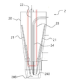
2 is a view showing a main configuration of a welding torch according to the present invention;
Hereinafter, embodiments of a welding torch according to the present invention will be described in detail with reference to the accompanying drawings.
FIG. 1 is a view showing a conventional gas tungsten arc welding method, and FIG. 2 is a view showing a main configuration of a welding torch according to the present invention.
Referring to FIG. 1, an inert gas is injected from a
However, with this method, the penetration depth is too deep, and there is a problem that the
Referring to FIG. 2, the
The
The
Accordingly, when electricity is applied to the
A power source may be connected to the other end of the
The
The filler
The
Therefore, the phenomenon of penetration of the
The
Therefore, according to the present invention, there is an advantage that the dilution rate between the base material and the filler (240) during welding can be minimized.
In addition, the present invention has an advantage that the
2: welding torch
20: torch body part
21: Tungsten electrode rod
22: gas channel
23: cooling water flow path
24:
200: arc generator
240:
Claims (5)
A tungsten electrode rod installed inside the torch body so that one end of the tungsten electrode rod can be positioned in the arc generating part, and electricity is applied so that the arc can be generated;
A gas flow path provided inside the torch body and guiding the inert gas to be discharged toward the arc generating part so that the arc can be smoothly generated;
A cooling water flow passage installed inside the torch body portion adjacent to the arc generating portion and through which cooling water for cooling the torch body portion heated by the arc flows; And
And a filler material supply unit installed in the torch body and guiding the arc material to be supplied to the arc generator,
Wherein the excipient is melted by the arc and can be sprayed on the surface of the workpiece.
Wherein the tungsten electrode rod is provided in a plurality of positions symmetrically with respect to the filler material supplied from the filler material supply unit.
Wherein the filler supplying portion is located at a central portion of the arc generating portion, and the tungsten electrode rod is positioned radially with respect to the filler.
Wherein the excipient supply portion includes a vibrating portion for applying vibration to the excipient supply portion,
Wherein when the excrement material is supplied through the excipient supply unit, the vibrating unit operates to minimize the drying of the excrement material.
Wherein the excipient is supplied through the excipient supply unit in a predetermined amount per unit time.
Priority Applications (1)
| Application Number | Priority Date | Filing Date | Title |
|---|---|---|---|
| KR1020150189354A KR101764032B1 (en) | 2015-12-30 | 2015-12-30 | Torch for welding |
Applications Claiming Priority (1)
| Application Number | Priority Date | Filing Date | Title |
|---|---|---|---|
| KR1020150189354A KR101764032B1 (en) | 2015-12-30 | 2015-12-30 | Torch for welding |
Publications (2)
| Publication Number | Publication Date |
|---|---|
| KR20170079131A true KR20170079131A (en) | 2017-07-10 |
| KR101764032B1 KR101764032B1 (en) | 2017-08-02 |
Family
ID=59355155
Family Applications (1)
| Application Number | Title | Priority Date | Filing Date |
|---|---|---|---|
| KR1020150189354A KR101764032B1 (en) | 2015-12-30 | 2015-12-30 | Torch for welding |
Country Status (1)
| Country | Link |
|---|---|
| KR (1) | KR101764032B1 (en) |
Cited By (3)
| Publication number | Priority date | Publication date | Assignee | Title |
|---|---|---|---|---|
| CN109262117A (en) * | 2018-10-17 | 2019-01-25 | 广东福维德焊接股份有限公司 | A kind of efficiently cooling lockhole effect TIG deep penetration welding welding gun |
| CN109352135A (en) * | 2018-11-29 | 2019-02-19 | 陕西燎原净化设备有限公司 | A kind of metal filtering core connection ring welding equipment |
| CN111112894A (en) * | 2020-01-08 | 2020-05-08 | 昆山天马精密机械有限公司 | Threaded water channel cooling device and method for electrode welding of automobile parts |
Families Citing this family (2)
| Publication number | Priority date | Publication date | Assignee | Title |
|---|---|---|---|---|
| KR102110706B1 (en) | 2019-02-25 | 2020-05-13 | 김인태 | Welding system and welding method capable of multi mode welding |
| KR102315992B1 (en) * | 2019-12-07 | 2021-10-21 | 디에스미래기술(주) | High density tig arc welding torch |
Family Cites Families (1)
| Publication number | Priority date | Publication date | Assignee | Title |
|---|---|---|---|---|
| JP5414571B2 (en) * | 2010-02-27 | 2014-02-12 | 日鐵住金溶接工業株式会社 | Transfer type plasma torch assembly, plasma welding apparatus, and plasma welding method |
-
2015
- 2015-12-30 KR KR1020150189354A patent/KR101764032B1/en active IP Right Grant
Cited By (4)
| Publication number | Priority date | Publication date | Assignee | Title |
|---|---|---|---|---|
| CN109262117A (en) * | 2018-10-17 | 2019-01-25 | 广东福维德焊接股份有限公司 | A kind of efficiently cooling lockhole effect TIG deep penetration welding welding gun |
| CN109262117B (en) * | 2018-10-17 | 2023-12-22 | 广东福维德焊接股份有限公司 | High-efficient refrigerated lockhole effect TIG deep penetration welding welder |
| CN109352135A (en) * | 2018-11-29 | 2019-02-19 | 陕西燎原净化设备有限公司 | A kind of metal filtering core connection ring welding equipment |
| CN111112894A (en) * | 2020-01-08 | 2020-05-08 | 昆山天马精密机械有限公司 | Threaded water channel cooling device and method for electrode welding of automobile parts |
Also Published As
| Publication number | Publication date |
|---|---|
| KR101764032B1 (en) | 2017-08-02 |
Similar Documents
| Publication | Publication Date | Title |
|---|---|---|
| KR101764032B1 (en) | Torch for welding | |
| ES2302306T3 (en) | SOLID IN SOLID STATE OR TIG WELDED WITH METAL TRANSFER THROUGH LIQUID BRIDGE. | |
| JP3200387U (en) | System using consumables with welding puddles | |
| US20090107958A1 (en) | Torch and Contact Tip for Gas Metal Arc Welding | |
| US20060175315A1 (en) | System and method of joining overlapping workpieces | |
| US20130001210A1 (en) | Metal cored welding method and system | |
| JP2013252540A (en) | Plasma welding torch and plasma welding device | |
| US20180236584A1 (en) | Welding method and arc welding device | |
| KR100770748B1 (en) | Wire heating apparatus for metal inert gas welding | |
| JP2019162646A (en) | Welding equipment | |
| CN105312739A (en) | Tungsten inert gas (TIG) welding device and method applicable to narrow-gap groove | |
| US1553543A (en) | Arc welding | |
| JP2015112636A (en) | Build-up welding device and method thereof | |
| SK18895A3 (en) | Method of longitudinal welding of pipes with flat steel and device for its realization | |
| KR102058698B1 (en) | torch for welding machine | |
| RU2660503C1 (en) | Device for laser-arc welding of the formulated pipe stock joint | |
| RU2660541C1 (en) | Method of laser-arc welding of the formulated pipe stock joint | |
| KR102046607B1 (en) | C-type filler feeding device for tig welding machine | |
| KR101846814B1 (en) | welding tip | |
| KR101754919B1 (en) | Nozzle for gas welding torch | |
| JP2010051998A (en) | Nozzle for torch of semiautomatic arc welding machine | |
| KR20170097172A (en) | Growing Welding Apparatus | |
| KR101468393B1 (en) | Torch for TIG welding self-feeding of flux and weld method | |
| KR20120044135A (en) | Gmaw welding torch with excellent molten weld pool protecting property | |
| JP3726813B2 (en) | Powder plasma welding apparatus and welding method |
Legal Events
| Date | Code | Title | Description |
|---|---|---|---|
| A201 | Request for examination | ||
| E902 | Notification of reason for refusal | ||
| E701 | Decision to grant or registration of patent right | ||
| GRNT | Written decision to grant |