KR20170063694A - Electrolytic cell for production of organic chemical hydrides - Google Patents
Electrolytic cell for production of organic chemical hydrides Download PDFInfo
- Publication number
- KR20170063694A KR20170063694A KR1020177009586A KR20177009586A KR20170063694A KR 20170063694 A KR20170063694 A KR 20170063694A KR 1020177009586 A KR1020177009586 A KR 1020177009586A KR 20177009586 A KR20177009586 A KR 20177009586A KR 20170063694 A KR20170063694 A KR 20170063694A
- Authority
- KR
- South Korea
- Prior art keywords
- anode
- electrolyte membrane
- cathode
- solid polymer
- electrolytic cell
- Prior art date
Links
Images


Classifications
-
- C—CHEMISTRY; METALLURGY
- C25—ELECTROLYTIC OR ELECTROPHORETIC PROCESSES; APPARATUS THEREFOR
- C25B—ELECTROLYTIC OR ELECTROPHORETIC PROCESSES FOR THE PRODUCTION OF COMPOUNDS OR NON-METALS; APPARATUS THEREFOR
- C25B3/00—Electrolytic production of organic compounds
- C25B3/20—Processes
- C25B3/25—Reduction
-
- C25B3/04—
-
- C—CHEMISTRY; METALLURGY
- C25—ELECTROLYTIC OR ELECTROPHORETIC PROCESSES; APPARATUS THEREFOR
- C25B—ELECTROLYTIC OR ELECTROPHORETIC PROCESSES FOR THE PRODUCTION OF COMPOUNDS OR NON-METALS; APPARATUS THEREFOR
- C25B11/00—Electrodes; Manufacture thereof not otherwise provided for
- C25B11/02—Electrodes; Manufacture thereof not otherwise provided for characterised by shape or form
-
- C—CHEMISTRY; METALLURGY
- C25—ELECTROLYTIC OR ELECTROPHORETIC PROCESSES; APPARATUS THEREFOR
- C25B—ELECTROLYTIC OR ELECTROPHORETIC PROCESSES FOR THE PRODUCTION OF COMPOUNDS OR NON-METALS; APPARATUS THEREFOR
- C25B11/00—Electrodes; Manufacture thereof not otherwise provided for
- C25B11/04—Electrodes; Manufacture thereof not otherwise provided for characterised by the material
- C25B11/042—Electrodes formed of a single material
- C25B11/043—Carbon, e.g. diamond or graphene
-
- C—CHEMISTRY; METALLURGY
- C25—ELECTROLYTIC OR ELECTROPHORETIC PROCESSES; APPARATUS THEREFOR
- C25B—ELECTROLYTIC OR ELECTROPHORETIC PROCESSES FOR THE PRODUCTION OF COMPOUNDS OR NON-METALS; APPARATUS THEREFOR
- C25B11/00—Electrodes; Manufacture thereof not otherwise provided for
- C25B11/04—Electrodes; Manufacture thereof not otherwise provided for characterised by the material
- C25B11/051—Electrodes formed of electrocatalysts on a substrate or carrier
- C25B11/052—Electrodes comprising one or more electrocatalytic coatings on a substrate
-
- C—CHEMISTRY; METALLURGY
- C25—ELECTROLYTIC OR ELECTROPHORETIC PROCESSES; APPARATUS THEREFOR
- C25B—ELECTROLYTIC OR ELECTROPHORETIC PROCESSES FOR THE PRODUCTION OF COMPOUNDS OR NON-METALS; APPARATUS THEREFOR
- C25B11/00—Electrodes; Manufacture thereof not otherwise provided for
- C25B11/04—Electrodes; Manufacture thereof not otherwise provided for characterised by the material
- C25B11/051—Electrodes formed of electrocatalysts on a substrate or carrier
- C25B11/073—Electrodes formed of electrocatalysts on a substrate or carrier characterised by the electrocatalyst material
- C25B11/075—Electrodes formed of electrocatalysts on a substrate or carrier characterised by the electrocatalyst material consisting of a single catalytic element or catalytic compound
- C25B11/077—Electrodes formed of electrocatalysts on a substrate or carrier characterised by the electrocatalyst material consisting of a single catalytic element or catalytic compound the compound being a non-noble metal oxide
-
- C—CHEMISTRY; METALLURGY
- C25—ELECTROLYTIC OR ELECTROPHORETIC PROCESSES; APPARATUS THEREFOR
- C25B—ELECTROLYTIC OR ELECTROPHORETIC PROCESSES FOR THE PRODUCTION OF COMPOUNDS OR NON-METALS; APPARATUS THEREFOR
- C25B13/00—Diaphragms; Spacing elements
- C25B13/04—Diaphragms; Spacing elements characterised by the material
- C25B13/08—Diaphragms; Spacing elements characterised by the material based on organic materials
-
- C25B9/10—
-
- C—CHEMISTRY; METALLURGY
- C25—ELECTROLYTIC OR ELECTROPHORETIC PROCESSES; APPARATUS THEREFOR
- C25B—ELECTROLYTIC OR ELECTROPHORETIC PROCESSES FOR THE PRODUCTION OF COMPOUNDS OR NON-METALS; APPARATUS THEREFOR
- C25B9/00—Cells or assemblies of cells; Constructional parts of cells; Assemblies of constructional parts, e.g. electrode-diaphragm assemblies; Process-related cell features
- C25B9/17—Cells comprising dimensionally-stable non-movable electrodes; Assemblies of constructional parts thereof
- C25B9/19—Cells comprising dimensionally-stable non-movable electrodes; Assemblies of constructional parts thereof with diaphragms
- C25B9/23—Cells comprising dimensionally-stable non-movable electrodes; Assemblies of constructional parts thereof with diaphragms comprising ion-exchange membranes in or on which electrode material is embedded
-
- Y—GENERAL TAGGING OF NEW TECHNOLOGICAL DEVELOPMENTS; GENERAL TAGGING OF CROSS-SECTIONAL TECHNOLOGIES SPANNING OVER SEVERAL SECTIONS OF THE IPC; TECHNICAL SUBJECTS COVERED BY FORMER USPC CROSS-REFERENCE ART COLLECTIONS [XRACs] AND DIGESTS
- Y02—TECHNOLOGIES OR APPLICATIONS FOR MITIGATION OR ADAPTATION AGAINST CLIMATE CHANGE
- Y02P—CLIMATE CHANGE MITIGATION TECHNOLOGIES IN THE PRODUCTION OR PROCESSING OF GOODS
- Y02P20/00—Technologies relating to chemical industry
- Y02P20/10—Process efficiency
- Y02P20/133—Renewable energy sources, e.g. sunlight
Abstract
본 발명은, 불포화 결합을 가지는 유기 화합물의 캐소드에서의 환원 반응을 높은 전류 효율로, 또한 작은 전력원 단위로 진행시킬 수 있는 유기 화학수소화물 제조용 전해 셀을 제공한다. 프로톤 전도성을 가지는 고체 고분자 전해질막(11)과, 고체 고분자 전해질막(11)의 한쪽 면에 설치되고, 피수소화물를 환원하여 수소화물을 생성하는 캐소드(12)와, 캐소드(12)를 수용하고, 피수소화물이 공급되는 캐소드실(13)과, 고체 고분자 전해질막(11)의 다른 쪽 면에 설치되고, 물을 산화하여 프로톤을 생성하는 전극 촉매 함유 애노드(14)와, 애노드(14)를 수용하고, 전해액이 공급되는 애노드실(15)을 포함한 유기 화학수소화물 제조용 전해 셀(10)이며, 고체 고분자 전해질막(11)의 캐소드(12) 측면 및 애노드(14) 측면 중 적어도 한쪽이 친수화되어 이루어진다. The present invention provides an electrolytic cell for the production of an organic chemical hydride capable of advancing a reduction reaction at an anode of an organic compound having an unsaturated bond at a high current efficiency and a small power source unit. A cathode 12 disposed on one side of the solid polymer electrolyte membrane 11 and generating a hydride by reducing a subject matter hydrate; and a solid polymer electrolyte membrane 11 having proton conductivity, (14) provided on the other surface of the solid polymer electrolyte membrane (11) to oxidize water to produce protons, and an anode catalyst layer Wherein at least one of the side surface of the cathode (12) and the side of the anode (14) of the solid polymer electrolyte membrane (11) is made hydrophilic .
Description
본 발명은, 유기 화학수소화물 제조용 전해 셀(이하, 단지 「전해 셀」이라고 도 칭함)에 관한 것이며, 상세하게는, 불포화 결합을 가지는 유기 화합물의 캐소드에서의 환원 반응을 높은 전류 효율로, 또한 작은 전력원 단위로서 진행시킬 수 있는 유기 화학수소화물 제조용 전해 셀에 관한 것이다. TECHNICAL FIELD The present invention relates to an electrolytic cell for producing an organic chemical hydride (hereinafter, simply referred to as an "electrolytic cell"), and more particularly to a cathode active material for a cathode for an organic compound having an unsaturated bond, To an electrolytic cell for the production of organic chemical hydrides which can proceed as a small power source unit.
일본국 전력 소비량은 연간 1,000TWh 정도이지만, 현재는 화력 발전이 원자력 발전분도 담당하고 있으므로, 화력 발전의 비율은 90%에 이르고 있다. 한편, 이산화탄소 배출량을 억제하기 위한 신에너지로서, 태양광, 풍력, 수력, 지열 발전 등의 재생 가능 에너지의 보급이 요망되고 있지만, 현 단계에서는 발전 전력량은 전체의 1% 정도에 지나지 않는다. 일본은 물 자원은 풍족하지만, 태양광이나 풍력에 관해서는 적지(適地)라고는 말하기 어렵고, 해외로부터의 에너지의 수송과 저장에 의존하지 않을 수 없는 것이 현 실정이다. 또한, 풍력 발전 및 대규모 태양광 발전에 의한 단주기의 출력 변동의 완화는 고려되고 있으나, 중장주기의 출력 변동의 완화나 대규모 에너지 수송에는 적용이 곤란하다. 그래서, 이들 재생 가능 에너지로부터 얻은 전력을 화학에너지로 변환하는 것이 유효하다고 생각된다. 전력을 직접 화학에너지로 변환하는 프로세스가 전기 화학 시스템이며, 2차 전지, 이른바 축전지는 전력을 화학에너지로 변환하여 저장하는 디바이스이며, 널리 사용되고 있다. The electricity consumption in Japan is about 1,000 TWh per year, but since thermal power generation is in charge of nuclear power generation, the percentage of thermal power generation reaches 90%. On the other hand, renewable energy such as solar power, wind power, hydro power, and geothermal power generation is required as new energy for suppressing carbon dioxide emissions, but the amount of generated electricity is only about 1% of the total. In Japan, water resources are abundant, but it is difficult to say that it is suitable for solar or wind power, and it is inevitable to rely on the transportation and storage of energy from abroad. Also, mitigation of short-period output fluctuations due to wind power generation and large-scale solar power generation is considered, but it is difficult to apply to the mitigation of output fluctuation of heavy period and large-scale energy transportation. Therefore, it is considered effective to convert the power obtained from these renewable energies into chemical energy. The process of converting electric power into direct chemical energy is an electrochemical system, and a secondary battery, a so-called battery, is a device that converts electric power into chemical energy and stores it, and is widely used.
재생 가능 에너지를 기반으로 하는 시스템으로서는, 세계적인 적지에 대규모 태양광 발전이나 풍력 발전 시스템을 설치하고, 에너지 캐리어(carrier)로 변환하고 수송하여 국내에서 에너지를 소비하는 시스템이 유망하다. 에너지 캐리어로서는 액체 수소, 암모니아, 유기 화학수소화물 등이 고려되고 있다. 그러나, 수소는 상온 상압에서 기체(氣體)이며, 수송, 저장에는 특수한 탱커가 필수로 된다는 문제점을 가지고 있다. 이와 같은 상황 중에서, 수소의 수송, 저장의 대체가 되는 시클로헥산이나 메틸시클로헥산, 데카린 등의 탄화수소를 사용한 유기 화학수소화물이 주목되고 있다. As a system based on renewable energy, a system that consumes domestic energy is promising as it installs a large-scale solar power generation or wind power generation system in a world-wide place, converts it into an energy carrier, and transports it. As energy carriers, liquid hydrogen, ammonia, organic chemical hydrides and the like are considered. However, hydrogen is a gas at room temperature and pressure, and has a problem that a special tanker is required for transportation and storage. Among such situations, organic chemical hydrides using hydrocarbons such as cyclohexane, methylcyclohexane, and decalin which are substitutes for transport and storage of hydrogen are attracting attention.
유기 화학수소화물로서 석유와 유사한 성상(性狀)의 액체를 선택하면, 비교적 대규모 시스템과의 친화성이 우수하고, 또한, 에너지 시스템의 말단까지의 배송 도 용이하다는 장점이 있다. 즉, 이들 유기 화학수소화물은, 상온 상압에서 액체이고 취급이 용이하며, 원료로 되는 유기 화합물을, 전기 화학적으로 수소 부가, 탈수소함으로써 수소 대신에 에너지 캐리어로서 저장, 운반이 가능하게 된다. When an organic chemical hydride is selected as a petroleum-like liquid, it has an advantage of being excellent in affinity with a relatively large-scale system and being easily delivered to the end of the energy system. That is, these organic chemical hydrides are liquid at room temperature and normal pressure, easy to handle, and can be stored and transported as energy carriers instead of hydrogen by electrochemically adding hydrogen and dehydrogenating organic compounds as raw materials.
종래, 메틸시클로헥산 등의 유기 화학수소화물의 제조에는, 재생 가능 에너지를 물 전해에 의해 수소를 제조하고, 톨루엔을 수소화 반응기에서 수소 부가하고메틸시클로헥산으로 변환하여 행해 왔으나, 전해 합성법이면, 직접 수소 부가함으로써 프로세스를 간략화할 수 있다. 또한, 전해 유기 화학수소화물 제조 방법은 규모에 관계없이 효율 손실이 적고, 기동 정지의 추종성이 우수하다. 또한, 고온 프로세스를 포함하는 시스템에서는, 효율이 저하되기 쉬운 비교적 소규모의 재생 가능 에너지의 거점에서는, 특히 효율면에서 우위로 에너지 변환하여 유기 화학수소화물의 에너지 저장ㆍ수송망에 실을 수가 있다. Conventionally, for the production of organic chemical hydrides such as methylcyclohexane, hydrogen has been produced by water electrolysis of renewable energy, and toluene is converted into methylcyclohexane by hydrogenation in a hydrogenation reactor. However, in the electrolytic synthesis method, By adding hydrogen, the process can be simplified. In addition, the method of producing electrolytic organic chemical hydrides has low efficiency loss regardless of scale, and is excellent in followability of starting and stopping. Further, in a system including a high-temperature process, energy can be efficiently converted into energy storage and transportation networks of organic chemical hydrides at a base of relatively small-scale renewable energy, which is likely to be inefficient.
이와 같은 유기 화학수소화물를 사용한 기술에 대하여, 지금까지 각종 검토가 이루어지고 있다. 예를 들면, 특허문헌 1, 2에서는, 불포화 결합을 가지는 유기 화합물을 환원하는 전해 셀에 대하여 제안되어 있다. 또한, 특허문헌 3, 4에서는, 유기 화합물로부터 막분리 장치를 사용하여 수소를 제조하는 장치에 대하여 제안되어 있다. 또한, 특허문헌 5에서는, 유기 화합물로부터 수소를 제조하여 연료 전지에 공급하는 장치에 대하여 제안되어 있다. 또한, 특허문헌 6, 7에서는, 유기 화합물의 전해 산화, 환원의 방법에 대하여 제안되어 있다. Various techniques for using such organic chemical hydrides have been studied up to now. For example, Patent Documents 1 and 2 propose an electrolytic cell for reducing an organic compound having an unsaturated bond. In Patent Documents 3 and 4, an apparatus for producing hydrogen using a membrane separation apparatus from an organic compound has been proposed. Patent Document 5 proposes an apparatus for producing hydrogen from an organic compound and supplying it to a fuel cell. In Patent Documents 6 and 7, a method of electrolytic oxidation and reduction of an organic compound has been proposed.
한편, 식염 전해 공업에 있어서는, 유격막의 2실형 전해 셀에 의해 식염을 전기 분해함으로써, 염소 가스, 수산화나트륨 및 수소를 동시에 제조하고 있다. 그러나, 전극과 격막을 접근하여 배치하고, 전해 전압의 저감을 행할 필요가 있으므로, 소수성을 가지는 막 표면에는 기포가 부착되고, 전류를 차폐하고 물질 이동을 저해하고, 셀 전압의 증대를 일으키는, 이른바 기포 효과가 알려져 있다. 특히, 불소계의 이온 교환막에는 발생하는 수소나 염소 가스가 기포로서 부착되기 쉽고, 특히 전극과 막의 거리를 2㎜ 이하로 접근시키면 기포의 영향으로 전해 전압이 상승하는 것, 염소보다 수소 쪽이 막에 부착되기 쉬운 것이 알려져 있다(비특허문헌 1). 이와 같은 문제점을 해결하기 위하여, 격막 표면을 친수화하여, 발생하는 기포의 격막으로의 부착을 억제하고, 전극-격막 근방에 기포를 체류시키지 않음으로써, 전해 전압의 저감이 실현되고 있다. (예를 들면, 특허문헌 8∼13)On the other hand, in the salt electrolysis industry, chlorine gas, sodium hydroxide, and hydrogen are produced at the same time by electrolyzing the salt by a double-chamber electrolytic cell of a channel. However, since it is necessary to arrange the electrodes and the diaphragm closer to each other and to reduce the electrolytic voltage, it is necessary to reduce the electrolytic voltage so that bubbles adhere to the surface of the hydrophobic film, The bubble effect is known. Particularly, hydrogen or chlorine gas generated in the fluorine-based ion exchange membrane tends to adhere as bubbles. Particularly, when the distance between the electrode and the membrane is approached to 2 mm or less, electrolytic voltage rises due to the effect of bubbles. (Refer to Non-Patent Document 1). In order to solve such a problem, reduction of the electrolytic voltage is realized by hydrophilizing the surface of the diaphragm, suppressing adhesion of the generated bubbles to the diaphragm, and not allowing the bubbles to stay near the electrode-diaphragm. (For example, Patent Documents 8 to 13)
유기 화학수소화물의 제조에 있어서는, 수용액인 애노드실 용액과 유기 화합물인 캐소드실 용액을 완전히 분리하기 위하여, 전해질막을 사용할 필요가 있다. 지금까지의 전해 유기 화학수소화물법에서는, 애노드에서 발생하는 산소 가스와 캐소드에서 부반응으로서 생성되는 수소 가스가, 전해질막에 부착되는 것에 의해 국소적으로 전류의 불균일화가 발생하고, 목적인 캐소드에서의 불포화 유기물의 환원을 방해하여, 전압 손실을 일으키고 있었다. 유기 화학수소화물의 제조 시의, 불포화 결합을 가지는 유기 화합물의 환원 반응의 예로서, 톨루엔(TL)을 원료로 하고, 메틸시클로헥산(MCH)을 환원 합성하는 식을 이하에 나타낸다. In the production of organic chemical hydrides, it is necessary to use an electrolyte membrane in order to completely separate the anode chamber solution, which is an aqueous solution, and the cathode chamber solution, which is an organic compound. In the electrolytic organic chemical hydride method so far, the oxygen gas generated in the anode and the hydrogen gas generated as a side reaction in the cathode adhere to the electrolyte membrane, thereby locally causing non-uniformity of the current. The reduction of the organic matter was disturbed, causing a voltage loss. As an example of the reduction reaction of an organic compound having an unsaturated bond in the production of an organic chemical hydride, an equation for reducing methylcyclohexane (MCH) using toluene (TL) as a raw material is shown below.
음극 반응:Cathode reaction:
TL + 6H+ +6e- → MCHTL + 6H + + 6e- - & gt ; MCH
양극 반응:Anode reaction:
2H2O → 4H+ + 4e- + O2 2H 2 O → 4H + + 4e- + O 2
전반응:All reactions:
2TL + 6 H2O → 2MCH + 3O2 2TL + 6H 2 O -> 2MCH + 3O 2
상기와 같이, 식염 전해와 마찬가지로, 기포 효과는 유기 화학수소화물 제조용 전해 셀에서도 발생하지만, 식염 전해의 막 표면 처리 기술이, 식염 전해 이외의 전해 프로세스에서 유효한지에 대해서는, 검토가 행해져 있지 않은 것이 현 실정이다. 특히, 기포 효과에 의한 전압 손실은, 고전류 시에 현저하다. As described above, although the bubble effect occurs in the electrolytic cell for the production of organic chemical hydrides as in the case of the salt electrolysis, the fact that the membrane surface treatment technique of the salt electrolysis is effective in the electrolytic process other than the salt electrolysis has not been studied It is true. In particular, the voltage loss due to the bubble effect is significant at high currents.
이에, 본 발명의 목적은, 불포화 결합을 가지는 유기 화합물의 캐소드에서의 환원 반응을 높은 전류 효율로, 또한 작은 전력원 단위로 진행시킬 수 있는 유기 화학수소화물 제조용 전해 셀을 제공하는 것에 있다. Accordingly, an object of the present invention is to provide an electrolytic cell for producing an organic chemical hydride, which is capable of advancing a reduction reaction at an anode of an organic compound having an unsaturated bond at a high current efficiency and a small power source unit.
본 발명자들은, 상기 문제점을 해소하기 위해 예의(銳意) 검토한 결과, 전해질막의 표면을 소정의 구조로 함으로써, 상기 문제점을 해소할 수 있는 것을 발견하고, 본 발명을 완성하기에 이르렀다. DISCLOSURE OF THE INVENTION The present inventors have conducted intensive investigations to solve the above problems, and as a result, they found that the above problem can be solved by making the surface of the electrolyte membrane have a predetermined structure, and have completed the present invention.
즉, 본 발명의 유기 화학수소화물 제조용 전해 셀은, 프로톤 전도성을 가지는 고체 고분자 전해질막과, 상기 고체 고분자 전해질막의 한쪽 면에 설치되고, 피(被)수소화물을 환원하여 수소화물을 생성하는 캐소드와, 상기 캐소드를 수용하고, 피수소화물이 공급되는 캐소드실과, 상기 고체 고분자 전해질막의 다른 쪽 면에 설치되고, 물을 산화하여 프로톤을 생성하는 전극 촉매 함유 애노드와, 상기 애노드를 수용하고, 전해액이 공급되는 애노드실을 포함한 유기 화학수소화물 제조용 전해 셀에 있어서, That is, an electrolytic cell for producing an organic chemical hydride of the present invention comprises: a solid polymer electrolyte membrane having proton conductivity; and a cathode disposed on one side of the solid polymer electrolyte membrane, for reducing hydrides to produce hydrides, A cathode chamber in which the cathode is accommodated and to which an excited gas is supplied; an electrode catalyst-containing anode which is provided on the other surface of the solid polymer electrolyte membrane and which oxidizes water to generate proton; In an electrolytic cell for producing an organic chemical hydride including an anode chamber to be supplied,
상기 고체 고분자 전해질막의 상기 캐소드 측면 및 상기 애노드 측면 중 적어도 한쪽이 친수화되어 이루어지는 것을 특징으로 한다. Wherein at least one of the cathode side surface and the anode side surface of the solid polymer electrolyte membrane is hydrophilized.
본 발명의 유기 화학수소화물 제조용 전극에서는, 상기 친수화가 상기 고체 고분자 전해질막의 표면의 요철화(凹凸化)인 경우, 요철화된 면의 JIS B 0601에서의 최대 높이를 30㎛ 이하로 하면 되고, 상기 친수화가 상기 고체 고분자 전해질막의 표면의 무기물층에 의한 피복인 경우, 상기 무기물층에 평균 입자 직경 0.005∼10㎛의 1차 입자를 30∼95 질량% 함유시키고, 또한 상기 무기물층의 피복량을 0.01∼10 mg/㎠로 해도 된다. 또한, 본 발명의 유기 화학수소화물 제조용 전극에서는, 상기 1차 입자가 주기율표 제4족, 제5족, 제13족 또는 제14족 원소인 산화물, 질화물 및 탄화물로부터 선택된 적어도 1종인 것이 바람직하다. 또한, 본 발명의 유기 화학수소화물 제조용 전극에서는, 상기 무기물층의 두께가 1∼80㎛인 것이 바람직하다. 여기서, 평균 입자 직경이란, 레이저 회절법에 의해 측정된 평균 입자 직경 D50을 의미한다. In the electrode for producing an organic chemical hydride of the present invention, when the hydrophilization is uneven on the surface of the solid polymer electrolyte membrane, the maximum height in JIS B 0601 of the uneven surface may be set to 30 μm or less, Wherein when the hydrophilization is performed by an inorganic material layer on the surface of the solid polymer electrolyte membrane, the inorganic material layer contains 30 to 95 mass% of primary particles having an average particle diameter of 0.005 to 10 占 퐉 and the covering amount of the inorganic material layer is And may be 0.01 to 10 mg / cm 2. In the electrode for producing an organic chemical hydride of the present invention, it is preferable that the primary particles are at least one selected from the group consisting of oxides, nitrides and carbides of Group 4, Group 5,
본 발명에 의하면, 유기 화학수소화물 제조 장치에서의 애노드에서 발생하는 산소, 또는 캐소드에서 발생하는 수소 가스가 전해질막에 부착되기 어려워져, 전류 집중을 방지할 수 있고, 불포화 결합을 가지는 유기 화합물을 고전류에서도 환원할 수 있다. 그 결과, 불포화 결합을 가지는 유기 화합물의 캐소드에서의 환원 반응을 높은 전류 효율로, 또한 작은 전력원 단위로 진행시킬 수 있는 유기 화학수소화물 제조용 전해 셀을 제공할 수 있다. According to the present invention, oxygen generated in the anode or hydrogen gas generated in the cathode in the organic chemical hydride production apparatus is hardly attached to the electrolyte membrane, and current concentration can be prevented, and an organic compound having an unsaturated bond It can also be reduced at high currents. As a result, it is possible to provide an electrolytic cell for producing an organic chemical hydride which can promote the reduction reaction at the cathode of an organic compound having an unsaturated bond at a high current efficiency and a small power source unit.
도 1은, 본 발명의 바람직한 일 실시형태에 관한 유기 화학수소화물 제조용 전해 셀의 개략적인 구성도이다.
도 2는, 정전압 전원의 출력 전압을 2.0V로 했을 때의 실시예 1, 실시예 2의 전해 셀의 전류 밀도의 경시적 변화와 비교예 1의 전해 셀의 전류 밀도의 경시적 변화를 나타낸 그래프이다.
도 3은, 전해 전압을 0.6V에서 3.8V까지 스위프시켰을 때의 실시예 3의 전해 셀의 전류 밀도와 비교예 1∼3의 전해 셀의 전류 밀도를 나타낸 그래프이다. BRIEF DESCRIPTION OF THE DRAWINGS Fig. 1 is a schematic diagram of an electrolytic cell for producing an organic chemical hydride according to a preferred embodiment of the present invention. Fig.
2 is a graph showing a change with time in the current density of the electrolytic cell of Example 1 and Example 2 and a change with time of the current density of the electrolytic cell of Comparative Example 1 when the output voltage of the constant- to be.
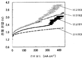
3 is a graph showing the current density of the electrolytic cell of Example 3 and the current density of electrolytic cells of Comparative Examples 1 to 3 when the electrolytic voltage was swept from 0.6 V to 3.8 V. FIG.
이하, 본 발명의 실시형태를, 도면을 참조하여 상세하게 설명한다. DESCRIPTION OF THE PREFERRED EMBODIMENTS Hereinafter, embodiments of the present invention will be described in detail with reference to the drawings.
도 1은, 본 발명의 바람직한 일 실시형태에 관한 유기 화학수소화물 제조용 전해 셀의 개략적인 구성도이다. 본 발명의 전해 셀(10)은, 프로톤 전도성을 가지는 고체 고분자 전해질막(이하, 「전해질막」이라고도 칭함)(11)과, 전해질막(11)의 한쪽 면에 설치되고, 피수소화물를 환원하여 수소화물을 생성하는 캐소드(12)와, 캐소드(12)를 수용하고, 피수소화물이 공급되는 캐소드실(13)과, 전해질막(11)의 다른 쪽 면에 설치되고, 물을 산화하여 프로톤을 생성하는 전극 촉매 함유 애노드(14)(이하, 단지 「애노드」라고도 칭함)와, 애노드(14)를 수용하고, 전해액이 공급되는 애노드실(15)을 포함하고 있다. 도시한 예에서는, 캐소드(12)는 캐소드 기재(基材)(12a)와, 그 표면에 형성된 캐소드 촉매층(12b)으로 이루어진다. BRIEF DESCRIPTION OF THE DRAWINGS Fig. 1 is a schematic diagram of an electrolytic cell for producing an organic chemical hydride according to a preferred embodiment of the present invention. Fig. The
또한, 도시한 예에서는, 캐소드실(13)은 최외부의 구획판(13a)과, 이 구획판(13a)의 주위 에지부와 전해질막(11) 사이에 배치된 스페이서(13b)로 이루어지고, 구획판(13a)과 캐소드(12) 사이에는, 캐소드 지지체(12c)가 개재되어 있다. 또한, 애노드실(15)은 최외부의 구획판(15a)과, 이 구획판(15a)의 주위 에지부와 전해질막(11) 사이에 배치된 스페이서(15b)로 이루어진다. 또한, 구획판(15a)과 애노드(14) 사이에는, 애노드(14) 지지용 탄성체(14a)가 더 배치되어 있고, 애노드(14)와 전해질막(11) 사이에는, 애노드 스페이서(16)가 배치되어 있다. 또한, 도시한 예에서는, 캐소드실(13)의 하부에는 피수소화물 입구(17)가 형성되고, 상부에는 수소화물 출구(18)가 형성되어 있고, 애노드실(15)의 하부에는 산성 전해질 입구(19)가 형성되고, 상부에는 산성 전해질 출구(20)가 형성되어 있다. In the illustrated example, the
본 발명의 전해 셀(10)에 있어서는, 전해질막(11)의 캐소드(12) 측면 및 애노드(14) 측면 중 적어도 한쪽이 친수화되어 이루어진다. 이러한 구성으로 함으로써, 캐소드(12)에서 발생한 수소 가스, 또는 애노드(14)에서 발생한 산소 가스가 전해질막(11)에 부착되기 어려워져, 전류 집중을 방지할 수 있고, 불포화 결합을 가지는 유기 화합물을 고전류에서도 환원할 수 있다. 본 발명의 전해 셀(10)에 있어서는, 전해질막(11)의 표면의 친수화의 방법으로서는, 전해질막(11) 표면의 요철화나, 전해질막(11) 표면의 무기물층에 의한 피복을 예로 들 수 있다. 이하, 본 발명의 전해 셀의 구성에 대하여 상세하게 설명한다. In the
[고체 고분자 전해질막][Solid Polymer Electrolyte Membrane]
본 발명의 전해 셀(10)에 사용하는 전해질막(11)으로서는, 산화 반응이나 유기 화합물 용매에 대한 장기 안정성이 우수한, 이온 교환기로서 술폰산을 가지는 불소 수지제 재료로 이루어지는 것이 바람직하다. 전해질막(11)은, 프로톤 전도성을 가지는 재료(아이오노머)로 형성되어 있고, 프로톤을 선택적으로 전도하는 한편, 캐소드(12)와 애노드(14) 사이에서 물질이 혼합되거나 확산되는 것을 억제한다. 전해질막(11)의 두께는, 5∼300㎛가 바람직하고, 10∼200㎛가 보다 바람직하고, 20∼100㎛가 특히 바람직하다. 전해질막(11)의 두께가 5㎛ 미만이면, 전해질막(11)의 배리어성이 저하되고, 크로스 리크(cross leak)가 생기기 쉬워진다. 또한, 전해질막(11)의 두께가 300㎛보다 두꺼워지면, 이온 이동 저항이 과대해지기 때문에 바람직하지 않다. As the
본 발명의 전해 셀(10)에 있어서는, 전술한 바와 같이, 전해질막(11)의 표면에 요철 형상을 부여함으로써 친수화해도 되고, 또한, 전해질막(11)의 표면에 무기물층을 피복하여 친수화해도 되고, 또한, 이들을 병용해도 된다. 전해질막(11)의 표면을 친수화하는 것에 의해, 캐소드(12)나 애노드(14)에서 발생한 가스의 전해질막(11) 표면으로의 부착을 방지할 수 있다. 친수화 처리는, 전해질막(11)의 애노드 측 또는 캐소드 측의 어느 면에 행해도 되고, 양면에 행해도 된다. 이 경우, 캐소드(12)에 의해 발생할 가능성이 있는 수소 가스가, 전해질막(11)이나 후술하는 캐소드 다공질 재료 내에 축적되는 것을 방지하고, 전해 성능, 선택성을 높일 수 있다. In the
여기서, 전해질막(11)에 대한 가스의 부착 방지의 메카니즘에 대하여 설명한다. 고체 표면의 액적이, 고체(S)-액체(L)-기체(V)가 공존하여 평형할 때, 표면 장력 γ에 대하여 Young 식이 성립한다. Here, the mechanism for preventing the adhesion of the gas to the
γSV=γSL+γLVcosθ, θ: 액체의 고체에 대한 접촉각γSV = γSL + γLVcosθ, θ: contact angle of the liquid with respect to the solid
액체로서 물을 사용했을 때 θ가 90° 이상인 큰 표면을 소수성, θ가 0에 가까운 표면을 친수성이라고 한다. 또한, 표면이 균일하지만 기하학적으로 불균일하게 거칠기가 존재할 경우, 겉보기 접촉각(θ')과 실제 접촉각의 사이에는 Wenzel 식이 성립한다. When water is used as a liquid, a large surface with a θ of 90 ° or more is considered to be hydrophobic, and a surface with a θ close to 0 is called hydrophilic. In addition, when the surface is uniform but geometrically nonuniform, the Wenzel equation is established between the apparent contact angle (θ ') and the actual contact angle.
cosθ'=rcosθ, r: 실제 표면적/곁보기 표면적≥1cos? '= rcos?, r: actual surface area / side view surface area? 1
이것은, θ> 90°이면 θ<θ', 즉 젖기 어려운 면은 조면(組面)으로 하면 점점 더 젖기 어려워지고, θ< 90°이면 θ>θ', 즉 젖기 쉬운 면은 조면으로 하면 점점 더 젖기 쉬워지는 것을 의미하고 있다. 일반적으로 시판되고 있는 이온 교환막의 물의 접촉각 θ는 90° 이하이므로, 이온 교환막의 표면을 요철화하면, 후자에 따라 젖기 쉬워진다. 따라서, 애노드(14)에서의 물 전해로 생성되는 산소 가스의 막 표면에서의 부착은 일어나기 어려워진다고 추정된다. 마찬가지로, 캐소드(12)에서의 유기계 용액의 막과의 접촉각도 90° 이하이며, 발생하는 수소의 부착을 효과적으로 방지할 수 있는 것이 추측된다. This is because, if θ> 90 °, θ <θ ', that is, the surface which is difficult to wet, becomes harder to wet with increasing surface roughness. If θ <90 °, θ> θ' Which means that it becomes easy to wet. Generally, since the contact angle of water of commercially available ion exchange membranes is 90 degrees or less, when the surface of the ion exchange membrane is made irregular, the latter becomes easy to wet. Therefore, it is presumed that the adhesion of the oxygen gas produced by the water electrolysis in the
전해질막(11)의 표면에 요철 형상을 부여하는 방법으로서, 예를 들면, 에머리 페이퍼 또는 페이스트상의 연마제를 사용하여, 전해질막(11)의 표면을 0.001㎛∼10㎛ 연마하는 방법을 들 수 있다. 에머리 페이퍼 또는 연마제는 예를 들면, 에머리 페이퍼는 2000번인 것을, 연마제는 연마 입경이 0.3㎛인 것을 사용하면 된다. 전해질막(11) 표면의 요철의 표면 거칠기인 최대 높이는, 바람직하게는 30㎛ 이하이며, 보다 바람직하게는 0.01㎛ 이상, 15㎛ 이하이다. 여기서, 최대 높이란, JIS B 0601에서의 최대 높이를 의미한다. As a method of imparting a concavo-convex shape to the surface of the
전해질막(11)의 표면을 무기물층으로 피복하는 경우, 1차 입자의 평균 입자 직경이 0.005∼10㎛, 바람직하게는, 0.01∼0.015㎛인 적어도 1종류의 무기물 입자를30∼95 질량% 함유하는 무기물층이 바람직하다. 이 경우, 무기물층을 1㎠당 0.01∼10mg 정도 피복하는 것이 바람직하다. 무기물층은, 바람직하게는 친수성을 가지는 불소계 중합체로 이루어지는 결합제 5∼70 질량%과 무기물 입자 30∼95 질량%로 이루어진다. When the surface of the
무기물층을 구성하는 1차 입자로서는, 주기율표 제4족, 제5족, 제13족, 또는 제14족 원소의 산화물, 질화물 및 탄화물로부터 선택된 적어도 1종인 것이 바람직하다. 특히, 지르코늄, 규소 및 티탄의 산화물, 질화물 또는 탄화물인 것이 바람직하다. The primary particles constituting the inorganic layer are preferably at least one selected from oxides, nitrides and carbides of Group 4, Group 5,
본 발명의 전해 셀(10)에 있어서는, 전해질막(11) 표면의 무기물층의 두께는 1∼80㎛가 바람직하고, 보다 바람직하게는 5∼30㎛이다. 무기물층의 두께가 80㎛보다 두껍게 되어도, 친수화에 의한 효과에는 거의 변화는 없고, 또한, 무기물막의 두께가 1㎛ 미만이면, 친수화의 효과를 충분히 얻을 수 없는 경우가 있기 때문이다. In the
본 발명의 전해 셀(10)에 있어서는, 애노드(14)나 캐소드(12)와 전해질막(11)과는 밀착되어 있어도 되지만, 도시한 바와 같이, 전해질막(11)과 애노드(14) 사이에 애노드 스페이서(16)를 배치하여, 애노드(14)와 전해질막(11) 사이에 갭을 형성하고 있어도 된다. 또한, 마찬가지로 캐소드(12)와 전해질막(11) 사이에도 갭을 형성해도 된다. In the
[캐소드][Cathode]
본 발명의 전해 셀(10)에 있어서는, 도시한 바와 같이, 캐소드(12)는 캐소드 기재(12a)와 캐소드 촉매층(12b)으로 구성할 수 있다. 본 발명의 전해 셀(10)의 캐소드(12)를 구성하는 캐소드 기재(12a)로서는, 다공 도전성 기재인 카본으로 이루어지는 크로스, 페이퍼 등의 섬유 소결체 등을 사용할 수 있다. 다공성 도전 기재로 하는 이유는, 가스 및 액체의 공급이나 제거를 위해, 적절한 다공성을 가지고 또한 충분한 전도성을 유지하는 것이 바람직하기 때문이다. 특히, 두께 0.01∼5㎜, 공극률이 30∼95%, 대표적 구멍 직경이 0.001∼1㎜인 것이 바람직하다. 그리고, 상기 캐소드 기재(12a)의 표면에 금속 성분을 공존시키면, 도전층 전체의 도전성이 향상되고, 전류의 균일화가 달성되므로 바람직하다. In the
카본 크로스는, 수㎛ 직경의 가는 카본 섬유를 수백개의 다발로 하고, 이것을 직포로 한 것이지만, 기액 투과성이 우수하므로 캐소드 기재(12a)로서 바람직하다. 또한, 카본 페이퍼는 카본 원료 섬유를 제지법에 의해 박막의 전구체(前驅體)로 하고, 이것을 소결한 것이지만, 이것도 바람직하게 사용할 수 있다. 이 탄소제 도전성 기재에 직접 급전하면, 그 불충분한 도전성 때문에, 전류의 국부 집중을 일으키고, 가스 확산층이나 반응층에도 국부적으로 집중된 전류가 공급되어 전해 효율을 저하시키지만, 금속 성분을 공존시킴으로써 도전성 기재에 균일하게 전류를 공급할 수 있다. The carbon cloth is made of a woven fabric made up of several hundred bundles of fine carbon fibers each having a diameter of several 탆, but it is preferable as the cathode base material 12a because of its excellent gas-liquid permeability. The carbon paper is obtained by sintering a carbon precursor fiber as a precursor of a thin film by a papermaking method, but this can also be preferably used. A direct current is locally concentrated on the gas diffusion layer or the reaction layer to lower the electrolytic efficiency. However, by coexisting the metal components, the conductive base material The current can be uniformly supplied.
[캐소드 촉매][Cathode catalyst]
캐소드 촉매의 종류로서는 백금, 루테늄, 팔라듐, 이리듐, 또는 이들의 합금으로부터 선택되는 금속의 입자를 사용할 수 있다. 이들은 시판되고 있는 입자를 사용해도 되지만, 공지의 방법에 의해 합성하여, 이것을 사용해도 된다. 예를 들면, 합성에는, 촉매 금속 이온을 용해하는 수용액에, 환원제를 혼합하여 합성하는 습식법을 채용해도 되고, 증착, 스퍼터 등의 건식법을 채용해도 된다. 캐소드 촉매의 입자의 입경은 0.001∼1㎛가 바람직하다. As the kind of the cathode catalyst, particles of a metal selected from platinum, ruthenium, palladium, iridium, or an alloy thereof can be used. Although commercially available particles may be used, they may be synthesized by a known method and used. For example, the synthesis may employ a wet method in which a reducing agent is mixed with an aqueous solution for dissolving catalyst metal ions, or a dry method such as vapor deposition or sputtering may be employed. The particle diameter of the particles of the cathode catalyst is preferably 0.001 to 1 mu m.
캐소드 촉매 입자는 반드시 캐소드 기재(12a)에 담지할 필요는 없지만, 담체 입자로서 카본 입자를 사용하고, 이 입자에 전개함으로써, 촉매 표면적을 유효하게 확대할 수 있다. 담체 입자로서, 통상은 탄소 미립자가 사용되고, 퍼니스 블랙, 아세틸렌 블랙 등을 사용할 수 있다. 탄소 미립자의 입경은 0.01∼1㎛가 바람직하다. 반응층 내의 도전성 분말은, 친수성 촉매 입자의 응집을 억제하는 기능을 가진다. The cathode catalyst particles do not necessarily have to be supported on the cathode substrate 12a, but the surface area of the catalyst can be effectively expanded by using carbon particles as the carrier particles and deploying them on the particles. As the carrier particles, usually carbon fine particles are used, and furnace black, acetylene black, and the like can be used. The particle size of the carbon fine particles is preferably 0.01 to 1 mu m. The conductive powder in the reaction layer has a function of suppressing aggregation of the hydrophilic catalyst particles.
[캐소드의 제조][Manufacture of cathode]
캐소드(12)의 제조 방법에 대해서는 특별히 제한은 없다. 예를 들면, 촉매 성분 분말, 소수성 수지, 물, 나프타 등의 용제, 아아이오노머인 Nafion(등록상표) 분산액 DE521(DuPont 제조)을 혼합하고, 건조 후의 질량이 촉매 중의 카본 질량과 1:10∼10:1의 비율이 되도록 첨가하여, 적절히 용매를 사용하여 도포용 촉매 잉크를 조제한다. 그 후, 상기 촉매 잉크를 캐소드 기재(12a)에 도포하고, 건조, 소성(燒成)에 의해 캐소드 촉매의 입자를 캐소드 기재(12a)에 고착시키면 된다. Nafion 분산액의 아아이오노머는, 다공성 구조체 내부에서의 도전성이 없는 유기 수소 화합물에서의 전자 이동 반응을 유지하기 때문에 유효하다. 소수성 수지(불소 성분)는 가스 투과성 재료이며, 그 분말의 입경으로서는 0.005∼10㎛가 바람직하다. 도포, 건조, 소성은 수회로 나누어 실시하면, 균질한 캐소드 촉매층(12b)을 얻을 수 있으므로 바람직하다. 이와 같이 하여 캐소드 촉매층(12b)을 가지는 캐소드(12)를 제작할 수 있다. The method of manufacturing the
본 발명의 전해 셀(10)에 있어서는, 촉매 잉크 성분을 사용하여 캐소드 촉매층을 전해질막(11) 상에 형성해도 된다. 전해질막(11)의 한쪽 면에 바코터 도포법에 의해 캐소드 촉매층을 형성하여, 캐소드-전해질막 복합체로 할 수도 있다. 상기 촉매 잉크를, 전해질막(11) 상에, 촉매 중의 Pt와 Ru를 합한 질량이 전극 면적당 0.5mg/㎠로 되도록 스프레이 도포하고, 잉크 중의 용매 성분을 건조하여, 전해질막-촉매의 접합체를 얻을 수도 있다. In the
캐소드 기재(12a)는 두께 방향으로 압력을 가하여 사용하므로, 이에 의해 두께 방향의 도전성이 변화하는 것은 바람직하지 않다. 성능 향상 및 20∼50%의 충전율을 가지는 캐소드으로 하는 목적으로, 프레스 가공을 행하는 것이 바람직하다. 프레스 가공은 탄소 재료를 압축함으로써 그 도전성을 높이고, 또한 압력을 가하여 사용했을 때의 충전율 및 도전성 변화를 안정화시키기 위해 행한다. 캐소드 촉매층(12b)과 캐소드 기재(12a)의 접합도가 향상되는 것도 도전성 향상에 기여한다. 또한, 캐소드 기재(12a)와 반응층의 압축, 및 캐소드 촉매층(12b)과 캐소드 기재(12a)의 접합도의 향상에 의하여, 원료 물질의 공급 및 생성 물질의 제거 능력이 증대한다. 프레스 가공 장치로서는, 핫 프레스, 핫 롤러 등의 공지의 장치를 이용할 수 있다. 프레스 조건으로서는, 실온∼360℃로써, 압력 0.1∼5MPa가 바람직하다. 이상에 의해, 높은 도전성과 반응성을 가지는 캐소드(12)를 제조할 수 있다. Since the cathode substrate 12a is used by applying pressure in the thickness direction, it is not preferable that the conductivity in the thickness direction is changed. For the purpose of improving the performance and the cathode having a filling rate of 20 to 50%, it is preferable to perform the press working. The press working is carried out in order to enhance the conductivity by compressing the carbon material and to stabilize the filling rate and the conductivity change when the carbon material is used under pressure. The improvement in the degree of bonding between the cathode catalyst layer 12b and the cathode substrate 12a also contributes to the improvement in conductivity. Further, by the compression of the cathode substrate 12a and the reaction layer, and the improvement of the degree of bonding of the cathode catalyst layer 12b and the cathode substrate 12a, the ability to supply the raw material and remove the generated material increases. As the press working apparatus, a known apparatus such as a hot press or a hot roller can be used. As the pressing condition, it is preferable to use a pressure of 0.1 to 5 MPa at room temperature to 360 deg. Thus, the
[애노드][Anode]
본 발명의 전해 셀(10)의 애노드(14)를 구성하는 애노드 기재로서는, 전해에 필요한 전류를 흐르게 하기 위한 충분한 전기 전도성을 가지고, 전해 셀(10)을 구성하는 기계적 강도의 필요성으로부터, 두께로서는 0.1㎜에서 2㎜의 판형 재료가 바람직하다. 가스 발생 전극에서는 기포에 의한 저항의 증대를 피하고, 피전해액의 공급을 촉진하므로, 다공체이며 산성 전해질에 대한 내식성이 우수한 것이 바람직하고, 티탄제 확장 메쉬(expanded mesh)가 범용되고 있다. 메쉬 가공 후에는 3차원적 구조로 되므로, 적절히 평활화 처리를 행한다. 최적인 확장 메쉬의 두께 범위는 0.1∼2㎜, 짧은 메쉬 방향 중심간 거리는 0.1∼4㎜, 긴 메쉬 방향 중심간 거리는 0.1∼6㎜, 개구율은 30∼70% 정도가 바람직하다. As the anode substrate constituting the
[애노드의 제조][Production of anode]
애노드(14)의 제조는, 바람직하게는, 애노드 기재로 되는 티탄의 표면에 건식 블라스트 처리, 이어서 20% 황산 등 수용액 중에서의 세정 처리를 행한다. 그 후, 세정한 애노드(14) 표면에, 아크 이온 플레이팅 장치에 의해, 티탄-탄탈층 등을 형성한다. 이것은 티탄 기재가 전해 중에 진행되는 부식을 억제하기 위해서이다. 티탄-탄탈층의 두께로서는, 0.1∼10㎛가 바람직하다. 그 후, 이리듐(Ir) 및 탄탈 성분을 용해시킨 혼합 수용액을 도포하고, 이어서, 전기로에 의해 360∼550℃의 열처리를 행하는 조작을 복수회 반복함으로써, 애노드를 제조할 수 있다. 본 발명의 전해 셀에 관한 애노드에서는, 산화이리듐과 산화탄탈로 이루어지는 전극 촉매층을, 전극 면적당 Ir 금속량 환산으로 1∼40g/㎡로 되도록 형성한 것을 애노드(14)로서 바람직하게 사용할 수 있다. The
[셀 구조][Cell structure]
도 1에 나타낸 본 발명의 전해 셀(10)의 캐소드실(13)의 최외부에는, 전자 전도성을 가지는 구획판(13a)이 설치되어 있다. 구획판(13a)은 예를 들면, 스테인레스 등의 금속으로 형성된다. 구획판(13a)의 주위 에지부와, 전해질막(11) 사이에 스페이서(13b)가 장착되어 있고, 구획판(13a), 스페이서(13b) 및 전해질막(11)으로 둘러싸인 공간이 캐소드실(13)로 되어 있다. 스페이서(13b)는, 피수소화물 및 수소화물을 포함하는 유기물이 캐소드실(13) 밖으로 누출되는 것을 방지하는 실링 부재(sealing member)를 겸하고 있고, 전자적으로 절연성인 것이 바람직하다. 스페이서(13b)의 재료로서는, 예를 들면, 4불화에틸렌 수지를 들 수 있다. At the outermost portion of the
도시한 예에서는, 스페이서(13b)의 하부에 피수소화물 입구(17)가 형성되어 있고, 상기 피수소화물 입구(17)로부터 캐소드실(13)에 톨루엔 등의 피수소화물이 공급된다. 또한, 스페이서(13b)의 상부에는 수소화물 출구(18)가 형성되어 있고, 상기 수소화물 출구(18)를 통하여 톨루엔의 수소화물인 메틸시클로헥산 등 수소화물을 포함하는 유기물이 계외(系外)로 배출된다. In the example shown in the figure, a
또한, 도시한 예에서는, 구획판(13a)과 캐소드(12) 사이에 캐소드 지지체(12c)가 설치되어 있다. 캐소드 지지체(12c)는, 후술하지만, 애노드 지지용 탄성체(14a)에 의해 가압되는 힘을 받아, 구획판(13a)과 캐소드(12) 사이의 전자 전도성을 확보한다. 또한, 캐소드 지지체(12c)는, 피수소화물와 수소화물의 흐름을 제어하는 유로도 형성하고 있다. Further, in the illustrated example, the
본 발명의 전해 셀(10)의 애노드실(15)의 외부에는, 전자 전도성을 가지는 구획판(15a)이 설치되어 있다. 구획판(15a)은 예를 들면, 티탄 등의 금속으로 형성된다. 구획판(15a)의 애노드(14) 측면의 주위 에지부와, 전해질막(11)의 사이에 스페이서(15b)가 장착되어 있고, 구획판(15a), 애노드실(15) 측단부의 스페이서(15b) 및 전해질막(11)으로 둘러싸인 공간이 애노드실(15)로 되어 있다. 스페이서(15b)는, 산성 전해액이 애노드실(15) 밖으로 누출되는 것을 방지하는 실링 부재를 겸하고 있고, 전자적으로 절연성인 것이 바람직하다. 스페이서(15b)의 재료로서는, 예를 들면, 4불화에틸렌 수지 등을 들 수 있다. A
도시한 예에서는, 스페이서(15b)의 하부에 산성 전해액 입구(19)가 형성되어 있고, 상기 산성 전해액 입구(19)로부터 애노드실(15)에 산성 전해액이 공급된다. 산성 전해액으로서는, 20℃에서 측정한 이온 전도도가 0.01S/cm 이상인 황산, 인산, 질산 또는 염산을 예로 들 수 있다. 산성 전해액의 이온 전도도가 0.01S/cm보다 낮으면, 공업적으로 충분한 전기 화학 반응을 얻기 어려워진다. 또한, 스페이서(15b)의 상부에는 산성 전해액 출구(20)가 형성되어 있고, 이 산성 전해액 출구(20)를 통하여 애노드실(15)에 저장되어 있는 산성 전해액이 계외로 배출된다. In the illustrated example, the acidic
또한, 도시한 예에서는, 애노드(14)와 구획판(15a) 사이에는 애노드 지지용 탄성체(14a)가 배치되어 있고, 애노드 지지용 탄성체(14a)에 의해 애노드(14)가 전해질막(11)에 가압된다. 애노드 지지용 탄성체(14a)는, 예를 들면, 판스프링이나 코일 구조의 전자 전도체로 형성된다. 도시한 예에서는, 애노드(14)와 전해질막(11) 사이에 애노드 스페이서(16)가 개재하고 있고, 애노드 스페이서(16)에 의해 애노드(14)와 전해질막(11) 사이에 소정의 갭이 유지되도록 구성되어 있다. 이와 같이, 애노드실(15)을 구성하는 구획판(15a)과 애노드(14) 사이에 애노드 지지용 탄성체(14a)를 설치하여 애노드(14)를 유지하는 구조로 함으로써, 애노드(14)의 교환 등의 유지보수 작업을 용이하게 할 수 있다. In the illustrated example, an anode supporting
애노드 지지용 탄성체(14a)는, 산성 전해액 입구(19)로부터 유입되는 산성 전해액에 대하여 내산성을 가지는 재료로 형성되는 것이 바람직하고, 기재로서 티탄 또는 티탄 합금이 바람직하게 사용된다. 애노드 지지용 탄성체(14a)를 구성하는 탄성체 구조로서는 V자형 스프링, X크로스 스프링, 쿠션 코일의 타입이나 채터 진동 절삭 방법(chatter vibration cutting method)에 의해 제작된 섬유의 집합체 등 각종 구조가 고려된다. 각각의 필요 면압은 각 부재의 접촉 저항을 감안하여, 재료 두께 등이 적절히 선택된다. The anode-supporting
<실시예><Examples>
이하, 본 발명의 실시예를 상세하게 설명하지만, 이들 실시예는, 본 발명을 바람직하게 설명하기 위한 예시에 지나지 않고, 전혀 발명을 한정하는 것은 아니다. Hereinafter, embodiments of the present invention will be described in detail, but these embodiments are merely examples for explaining the present invention, and the present invention is not limited at all.
<실시예 1>≪ Example 1 >
전해질막으로서 NRE212CS(DuPont 제조, 두께 25㎛)를 사용하고, 애노드 측면에 5㎛의 두께를 가지는 산화지르코늄층을 형성하여 친수화하였다. 전해질막의 캐소드 측면 상의 캐소드 촉매층의 형성에 있어서는, 먼저, PtRu/C 촉매 TEC61E54E[다나카 귀금속 공업(Tanaka Kikinzoku Kogyo) 제조, Pt 23 질량%, Ru 27 질량%] 분말에 아아이오노머 Nafion(등록상표) 분산액 DE521(DuPont 제조)을, 건조 후의 질량이 촉매 중의 카본 질량과 4:5의 질량이 되도록 첨가하여, 적절히 용매를 사용하여 도포용 잉크를 조제하였다. 상기 잉크를 전해질막 상에, 촉매 중의 Pt와 Ru를 합한 질량이 전극 면적당 0.5mg/㎠로 되도록 스프레이 도포하고, 이어서, 70℃에서 잉크 중의 용매 성분을 건조하여 캐소드 촉매층을 얻어, 캐소드 촉매층-전해질막 접합체로 하였다. As the electrolyte membrane, NRE212CS (manufactured by DuPont, thickness 25 mu m) was used, and a zirconium oxide layer having a thickness of 5 mu m was formed on the side of the anode to make it hydrophilic. In the formation of the cathode catalyst layer on the cathode side of the electrolyte membrane, first, a dispersion of an ionomer Nafion (registered trademark) was added to a PtRu / C catalyst TEC61E54E (manufactured by Tanaka Kikinzoku Kogyo, Pt 23 mass%, Ru 27 mass% DE521 (manufactured by DuPont) was added so that the mass after drying became the mass of the carbon mass in the catalyst of 4: 5, and the coating ink was appropriately prepared using a solvent. The ink was spray-applied on the electrolyte membrane so that the mass of Pt and Ru in the catalyst was 0.5 mg / cm 2 per electrode area. Subsequently, the solvent component in the ink was dried at 70 캜 to obtain a cathode catalyst layer, Membrane assembly.
얻어진 캐소드 촉매층-전해질막 접합체의 캐소드 촉매층 표면에, 전극면에 맞추어 잘라낸 캐소드 확산층 SGL35BC(SGL 카본 제조)를 접합하고, 120℃, 1MPa로 2분간 처리하여, 캐소드-전해질막 복합체를 형성하였다. A cathode diffusion layer SGL35BC (manufactured by SGL Carbon) cut in accordance with the electrode surface was bonded to the surface of the cathode catalyst layer of the obtained cathode catalyst layer-electrolyte membrane junction body and treated at 120 DEG C and 1 MPa for 2 minutes to form a cathode-electrolyte membrane composite.
캐소드 구획판과 캐소드 지지체를 접합한 구조체로서, 카본/에폭시 수지를 몰드 성형한 카본계 구조체를 사용하였다. 이 구조체의 캐소드 지지체 부분은 캐소드 확산층에 접하는 면에 액체 유통을 위한 유로를 복수 형성하고 있고, 이 유로 하나는, 폭 1㎜, 유로 높이 0.5㎜의 공극부를 가지고, 유로간 간격 1㎜의 스트레이트 형상이며, 유기 화학수소화물 제조 장치를 설치할 때의 연직 방향과 유로가 평행하게 되도록 설치하였다. 또한, 구조체의 유로의 양단(兩端)은, 복수의 유로를 통합하여 액체 공급 및 배출을 위한 액체 헤더를 가지고 있고, 이것을 통하여 유기물의 공급 및 배출용 경로에 접속하였다. A carbon-based structure in which a carbon / epoxy resin was molded by molding was used as a structure obtained by joining the cathode partition plate and the cathode support. The cathode support portion of the structure has a plurality of flow paths for liquid flow on the surface contacting the cathode diffusion layer. One of the flow paths has a gap portion of 1 mm in width and 0.5 mm in channel height, and has a straight shape , And the vertical direction and the flow path when the organic chemical hydride manufacturing apparatus is installed are arranged so as to be parallel to each other. Both ends of the flow path of the structure have a liquid header for supplying and discharging liquid by integrating a plurality of flow paths, and connected to a path for supplying and discharging the organic matter through the liquid header.
애노드 기재로서, 두께 1.0㎜, 짧은 메쉬 중심간 거리 3.5㎜, 긴 메쉬 방향 중심간 거리 6.0㎜의 확장 메쉬를 사용하였다. 애노드 기재의 표면에 건식 블라스트 처리, 이어서 20% 황산 수용액 중에서의 세정 처리를 행하였다. 그 후, 세정한 애노드 기재의 표면을, 아크 이온 플레이팅 장치와 티탄-탄탈 합금판을 사용하여, 기재 온도 150℃, 진공도 1.3Pa로 하여 코팅 두께 2㎛로 피복하였다. 이와 같이 하여 얻은 애노드 기재에 대하여, 사염화이리듐/오염화탄탈의 혼합 수용액을 도포하고, 이어서, 전기로에서 550℃의 열처리를 행하는 조작을 복수회 반복함으로써, 산화이리듐과 산화탄탈로 이루어지는 전극 촉매층을, 전극 면적당 Ir 금속량 환산으로 12g/㎡로 되도록 형성한 것을 애노드로 하였다. As the anode substrate, an enlarged mesh having a thickness of 1.0 mm, a short mesh center distance of 3.5 mm, and a long mesh direction center distance of 6.0 mm was used. The surface of the anode substrate was subjected to a dry blast treatment and then a cleaning treatment in a 20% sulfuric acid aqueous solution. Thereafter, the surface of the washed anode substrate was coated with a coating thickness of 2 탆 by using an arc ion plating apparatus and a titanium-tantalum alloy plate at a substrate temperature of 150 캜 and a degree of vacuum of 1.3 Pa. An electrode catalyst layer made of iridium oxide and tantalum oxide was formed by applying an aqueous solution of a mixture of iridium tetrachloride and tantalum pentachloride on the thus obtained anode substrate and then performing heat treatment at 550 DEG C in an electric furnace a plurality of times, And 12 g / m 2 in terms of Ir metal amount per electrode area.
애노드 지지용 탄성체로서 두께 0.3㎜의 Ti판을 가공한 10㎜피치의 평스프링을 나란히 한 형상으로 한 탄성체를 사용하였다. 평스프링의 애노드 접촉면에는, 미량의 백금층을 형성하였다. As the anode supporting elastic body, an elastic body having a flat spring of 10 mm pitch formed by machining a Ti plate with a thickness of 0.3 mm was used. On the anode contact surface of the flat spring, a small amount of platinum layer was formed.
이들 셀 부재, 즉 캐소드 지지체, 캐소드-전해질막 접합체, 애노드, 애노드 지지용 탄성체를 상기 순서로 적층하고, 애노드 측의 구획판과 애노드 사이에 애노드 지지용 탄성체를 삽입함으로써, 고정된 셀 폭 내에서 애노드 측으로부터의 가압력에 의해 각 층이 밀착되는 형태로 압압(押壓)되게 하였다. 그리고, 애노드 스페이서의 두께는 25㎛로 하였다. By stacking these cell members, that is, the cathode support, the cathode-electrolyte membrane junction body, the anode, and the anode supporting elastic body in this order, and inserting the anode supporting elastic member between the anode side partition plate and the anode, So that each layer is pressed by a pressing force from the anode side. The thickness of the anode spacer was 25 mu m.
이와 같이 하여 얻어진 전해 셀의 캐소드실에 톨루엔을 연직 방향을 따라 아래에서 위(라이저)로 유통시키고, 또한 애노드와 애노드 측의 구획판과 사이의 공극부(애노드실)에 5% 황산 수용액을 동일하게 라이저로 유통시키고, 정전압 전원의 음극을 캐소드, 양극을 애노드에 접속하여, 이하의 전해 반응을 실시하였다. 각 유체의 순환 유속은, 선속도로서 캐소드 측이 1m/min, 애노드 측이 3m/min으로 되도록 하였다. Toluene was flowed from below to above (riser) in the cathode chamber of the electrolytic cell thus obtained, and a 5% sulfuric acid aqueous solution was supplied to the space (anode chamber) between the anode and the partition plate on the anode side The negative electrode of the constant voltage power source was connected to the cathode and the positive electrode was connected to the anode, and the following electrolytic reaction was performed. The circulating flow rate of each fluid was such that the linear velocity was 1 m / min on the cathode side and 3 m / min on the anode side.
<실시예 2>≪ Example 2 >
전해질막의 애노드 측의 표면을 요철화하여 친수화 처리를 행한 것 이외에는, 실시예 1과 동등한 전해 셀로 하였다. 요철의 최대 높이는 10㎛였다. The electrolytic cell was the same as that in Example 1 except that the surface of the anode side of the electrolyte membrane was made irregular and hydrophilized. The maximum height of the unevenness was 10 mu m.
<실시예 3>≪ Example 3 >
전해질막의 애노드 측의 표면을 2000번의 에머리 페이퍼로 연마하고, 5㎛의 두께를 가지는 산화지르코늄층을 더 형성하고 친수화를 행한 것 이외에는, 실시예 1과 동등한 전해 셀로 하였다. 요철의 최대 높이는 15㎛였다. The electrolytic cell was the same as that of Example 1 except that the surface of the anode side of the electrolyte membrane was polished with 2000 emery paper to further form a zirconium oxide layer having a thickness of 5 占 퐉 and hydrophilization was performed. The maximum height of the unevenness was 15 탆.
<비교예 1>≪ Comparative Example 1 &
친수화 처리를 행하지 않은 것 이외에는, 실시예 1과 동등한 셀로 하였다. The cell was the same as that of Example 1 except that the hydrophilization treatment was not performed.
<비교예 2>≪ Comparative Example 2 &
친수화 처리를 행하지 않고, 스페이서의 두께를 50㎛로 한 것 이외에는, 실시예 1과 동등한 셀로 하였다. A cell equivalent to that of Example 1 was obtained, except that the hydrophilic treatment was not performed and the thickness of the spacer was 50 탆.
<비교예 3>≪ Comparative Example 3 &
친수화 처리를 행하지 않고, 스페이서의 두께를 200㎛로 한 것 이외에는, 실시예 1과 동등한 셀로 하였다. A cell equivalent to that of Example 1 was obtained, except that the hydrophilic treatment was not performed and the thickness of the spacer was changed to 200 mu m.
(성능 평가)(Performance evaluation)
도 2는, 정전압 전원의 출력 전압을 2.0V로 했을 때의 실시예 1, 실시예 2의 전해 셀의 전류 밀도의 경시적 변화와 비교예 1의 전해 셀의 전류 밀도의 경시적 변화를 나타낸 그래프이다. 동일한 전압에도 불구하고, 실시예 1, 실시예 2쪽이 비교예보다 높은 전류 밀도를 얻을 수 있었다. 또한, 비교예 1은 초기에 큰 전압 저하가 인지되었다. 이로부터, 실시예 1, 실시예 2는 비교예 1에 비하여, 애노드 측에서 발생하는 산소 가스가 전해질막에 부착되지 않고 상부로 빠지기 때문에, 전해질막 상에서의 국소적인 전류 집중과 애노드 측 가스 블로킹에 따른 과전압 상승이 일어나지 않고, 높은 전류 밀도를 얻을 수 있었다고 고찰할 수 있다. 또한, 실시예 1, 실시예 2에서, 캐소드 측의 전위가 불안정하게 되는 것에 의한 순간적인 수소 발생[유기물 환원에 대한 패러데이(Faraday) 효율의 저하]은 보이지 않고, 전해 반응 중의 애노드 상태가 양호한 것에 의해, 캐소드 반응도 바람직하게 진행되고 있는 것이 확인되었다. 2 is a graph showing a change with time in the current density of the electrolytic cell of Example 1 and Example 2 and a change with time of the current density of the electrolytic cell of Comparative Example 1 when the output voltage of the constant- to be. Despite the same voltage, the current density of Example 1 and Example 2 was higher than that of Comparative Example. Also, in Comparative Example 1, a large voltage drop was initially recognized. From this, in Examples 1 and 2, compared to Comparative Example 1, oxygen gas generated on the anode side does not adhere to the electrolyte membrane but falls into the upper portion. Therefore, local current concentration on the electrolyte membrane and gas blocking on the anode side It can be considered that a high current density can be obtained without causing an increase in the overvoltage. In Examples 1 and 2, momentary hydrogen generation (lowering of Faraday efficiency against organic matter reduction) due to instability of the potential at the cathode side was not observed, and the anode state during the electrolysis reaction was not good , It was confirmed that the cathode reaction was also favorably proceeding.
도 3은, 전해 전압을 0.6V에서 3.8V까지 스위프시켰을 때의 실시예 3의 전해 셀의 전류 밀도와 비교예 1∼3의 전해 셀의 전류 밀도를 나타낸 그래프이다. 실시예 3은 저전류역으로부터 고전류역에 걸쳐, 낮은 전압이었다. 이에 대하여, 비교예 2, 비교예 3에서는 200mA/㎠ 이상에서는 전류가 진동하면서 급격하게 셀 전압이 상승하였다. 이것은 애노드에서 발생한 산소 기포의 영향으로 생각된다. 스페이서를 25㎛로 하여 전해질막을 친수화한 비교예 1의 분극 곡선은, 300mA/㎠를 초과할 때까지 셀 전압의 진동은 보이지 않았다. 이로부터, 전해질막을 친수화하는 것에 의해, 애노드에서 발생하는 산소 또는 캐소드에서 약간 발생하는 수소의 전해질막으로의 부착이 억제되고, 가스의 배출이 촉진되기 때문에, 저항이 저감되고, 또한, 기포에 의한 반응 집중이 억제되고, 과전압이 감소하고, 전해 셀 전압이 저감할 수 있었다고 생각된다. 3 is a graph showing the current density of the electrolytic cell of Example 3 and the current density of electrolytic cells of Comparative Examples 1 to 3 when the electrolytic voltage was swept from 0.6 V to 3.8 V. FIG. Example 3 showed a low voltage across the high current range to the low current range. On the other hand, in Comparative Example 2 and Comparative Example 3, the cell voltage was abruptly increased while the current oscillated at 200 mA / cm 2 or more. This is thought to be the effect of oxygen bubbles generated in the anode. The polarization curve of Comparative Example 1 in which the electrolyte was made hydrophilic by setting the spacer to 25 mu m showed no cell voltage oscillation until the polarization curve exceeded 300 mA / cm < 2 >. From this, since the electrolyte film is hydrophilized, adhesion of oxygen generated from the anode or hydrogen slightly generated in the cathode to the electrolyte membrane is suppressed and the discharge of gas is promoted, so that the resistance is reduced, It is considered that the concentration of the reaction by the electrolytic cell can be suppressed, the overvoltage can be reduced, and the electrolytic cell voltage can be reduced.
<실시예 4><Example 4>
소수성 카본 블랙[덴키 가가쿠 고교 가부시키가이샤(Denki Kagaku Kogyo Co., Ltd. )제조의 AB-6]과 PTFE 물 현탁액[미쓰이 플로로케미컬 가부시키가이샤(Mitsui Fluorochemicals Company, Ltd.) 제조의 31JR]을 혼합하고, 20 질량%에 상당하는 트라이톤(등록상표)을 용해한 수중에서 충분히 교반한 후, 얻어진 혼합 현탁액을, 투영 면적당 카본 블랙의 질량이 108g/㎡로 되도록 두께 0.4㎜의 카본 크로스[발라드(Ballard) 제조]에 도포하고, 캐소드 기재로 하였다. 다음에, 소수성 카본 블랙(덴키 가가쿠 고교 가부시키가이샤 제조의 AB-6), 친수성 카본 블랙(덴키 가가쿠 고교 가부시키가이샤 제조의 AB-12), Pt-Ru 입자와 Nafion액(미쓰이 플로로케미컬 가부시키가이샤 제조의 31JR)을 혼합하고, 이 혼합 현탁액을, 투영 면적당 촉매 질량이 0.5mg/㎠로 되도록 두께 0.5㎜의 캐소드 기재에 도포하였다. 그 후, 60℃에서 건조하고, 전기로 내에서 305℃로 15분 소성하고, 압력 0.6MPa로 프레스 가공을 행하고, 가스 확산 캐소드의 충전율이 40%로 되도록 하여, 캐소드를 제작하였다. A hydrophobic carbon black (AB-6, manufactured by Denki Kagaku Kogyo Co., Ltd.) and a PTFE water suspension (31JR, manufactured by Mitsui Fluorochemicals Company, Ltd.) ], And the mixture was sufficiently stirred in water containing Triton (registered trademark) dissolved in an amount of 20% by mass. Thereafter, the resulting mixed suspension was dispersed in carbon black having a thickness of 0.4 mm so as to have a mass of carbon black per projected area of 108 g / (Manufactured by Ballard), thereby obtaining a cathode substrate. Next, a hydrophobic carbon black (AB-6 manufactured by Denki Kagaku Kogyo Kabushiki Kaisha), a hydrophilic carbon black (AB-12 manufactured by Denki Kagaku Kogyo K.K.), a Pt-Ru particle and a Nafion solution 31JR manufactured by Chemical Industries, Ltd.) was mixed, and this mixed suspension was applied to a cathode substrate having a thickness of 0.5 mm so that the catalyst mass per projected area was 0.5 mg / cm 2. Thereafter, the resultant was dried at 60 占 폚, baked at 305 占 폚 for 15 minutes in an electric furnace, and press-processed at a pressure of 0.6 MPa to prepare a cathode so that the packing ratio of the gas diffusion cathode was 40%.
전해질막의 양면을 2㎛의 요철이 형성되도록 연마하여 친수화한 막을 사용하여, 실시예 1과 동일한 전해 셀을 조립하였다. 애노드에는 1M 황산 수용액을 10mL/min, 캐소드에는 톨루엔을 5mL/min를 도입하고, 셀 온도는 60℃로 하고, 400mA/㎠일 때, 셀 전압은 2.15V였다. 고전류 밀도역까지 셀 전압은 진동하지 않았다. 전류 효율은 95%였다. The same electrolytic cell as in Example 1 was assembled by using a membrane obtained by polishing both surfaces of the electrolyte membrane so as to form concave and convex portions of 2 占 퐉. A 1 M sulfuric acid aqueous solution was introduced into the anode at 10 mL / min, and a toluene at 5 mL / min was introduced into the cathode. The cell temperature was 60 DEG C and the cell voltage was 2.15 V at 400 mA / cm2. The cell voltage did not oscillate up to the high current density station. The current efficiency was 95%.
<실시예 5>≪ Example 5 >
전해질막의 애노드 측만 친수화한 것 이외에는, 실시예 4와 동일한 전해 셀을 제작하고 성능 측정을 행한 바, 400mA/㎠일 때 2.2V였다. 또한, 고전류 밀도역까지 셀 전압의 진동은 보이지 않았다. 전류 효율은 95%였다. The same electrolytic cell as in Example 4 was fabricated except that only the anode side of the electrolyte membrane was hydrophilized, and the performance was measured, and it was 2.2 V at 400 mA / cm 2. In addition, the cell voltage oscillation was not observed up to the high current density region. The current efficiency was 95%.
<비교예 4>≪ Comparative Example 4 &
전해질막을 친수화하지 않은 것 이외에는, 실시예 4와 동일한 전해 셀을 제작하고 성능 측정을 행한 바, 300mA/㎠일 때 2.2V였다. 고전류 밀도역에서 셀 전압의 진동이 보였다. 전류 효율은 90%였다. Except that the electrolyte membrane was not hydrophilized, the same electrolytic cell as in Example 4 was fabricated and the performance was measured, and it was 2.2 V at 300 mA / cm 2. The cell voltage oscillation was observed at the high current density region. The current efficiency was 90%.
본 발명은, 전술한 실시형태에 한정되지 않고, 당업자의 지식에 기초하여 각종 설계 변경 등의 변형을 가하는 것도 가능하며, 그와 같은 변형이 가해진 실시형태도 본 발명의 범위에 포함될 수 있는 것이다. The present invention is not limited to the above-described embodiments, and it is possible to apply various modifications such as design changes based on the knowledge of those skilled in the art, and embodiments in which such modifications are made are also included in the scope of the present invention.
10 : 유기 화학수소화물 제조용 전해 셀(전해 셀)
11 : 고체 고분자 전해질막(전해질막)
12 : 캐소드
12a : 캐소드 기재
12b : 캐소드 촉매층
12c : 캐소드 지지체
13 : 캐소드실
13a : 구획판
13b: 스페이서
14 : 전극 촉매 함유 애노드(애노드)
14a : 애노드 지지용 탄성체
15 : 애노드실
15a : 구획판
15b : 스페이서
16 : 애노드 스페이서
17 : 피수소화물 입구
18 : 수소화물 출구
19 : 산성 전해액 입구
20 : 산성 전해액 출구10: Electrolytic cells for the production of organic chemical hydrides (electrolytic cells)
11: Solid polymer electrolyte membrane (electrolyte membrane)
12: Cathode
12a: cathode substrate
12b: cathode catalyst layer
12c: cathode support
13: cathode chamber
13a: partition plate
13b: Spacer
14: Electrode catalyst-containing anode (anode)
14a: an elastic body for supporting the anode
15: anode thread
15a: partition plate
15b: Spacer
16: anode spacer
17: Entrance of the digestion package
18: Hydride exit
19: Acid electrolyte inlet
20: Acidic electrolyte outlet
Claims (5)
상기 고체 고분자 전해질막의 상기 캐소드 측면 및 상기 애노드 측면 중 적어도 한쪽이 친수화되어 이루어지는 유기 화학수소화물 제조용 전해 셀. A solid polymer electrolyte membrane having proton conductivity; a cathode provided on one side of the solid polymer electrolyte membrane for reducing hydride to produce hydride; a cathode chamber for containing the cathode and supplied with a saccharide; An electrolytic cell for producing organic chemical hydrides, comprising an anode containing an anode catalyst and an anode catalyst, provided on the other surface of the solid polymer electrolyte membrane, for oxidizing water to generate proton, and an anode chamber for receiving the anode,
Wherein at least one of the cathode side surface and the anode side surface of the solid polymer electrolyte membrane is hydrophilized.
상기 친수화로서, 상기 고체 고분자 전해질막의 표면에 요철화(凹凸化)가 행해지고, 요철화된 면의 JIS B 0601에서의 최대 높이가 30㎛ 이하인, 유기 화학수소화물 제조용 전해 셀. The method according to claim 1,
Wherein the surface of the solid polymer electrolyte membrane is subjected to irregularities and the maximum height of the uneven surface in JIS B 0601 is 30 占 퐉 or less as the hydrophilization.
상기 친수화로서, 상기 고체 고분자 전해질막의 표면에 무기물층에 의한 피복이 행해지고, 상기 무기물층이 평균 입자 직경 0.005∼10㎛의 1차 입자를 30∼95 질량% 함유하고, 또한 상기 무기물층의 피복량이 0.01∼10mg/㎠인, 유기 화학수소화물 제조용 전해 셀. The method according to claim 1,
Wherein the hydrophilic layer is formed by coating an inorganic layer on the surface of the solid polymer electrolyte membrane, wherein the inorganic layer contains 30 to 95 mass% of primary particles having an average particle diameter of 0.005 to 10 占 퐉, The electrolytic cell for the production of an organic chemical hydride having an amount of 0.01 to 10 mg / cm 2.
상기 1차 입자가, 주기율표 제4족, 제5족, 제13족 또는 제14족 원소의 산화물, 질화물 및 탄화물로부터 선택된 적어도 1종인, 유기 화학수소화물 제조용 전해 셀. The method of claim 3,
Wherein the primary particles are at least one selected from oxides, nitrides and carbides of Group 4, Group 5, Group 13, or Group 14 elements of the Periodic Table of the Elements.
상기 무기물층의 두께가 1∼80㎛인, 유기 화학수소화물 제조용 전해 셀. The method of claim 3,
Wherein the inorganic layer has a thickness of 1 to 80 占 퐉.
Applications Claiming Priority (3)
| Application Number | Priority Date | Filing Date | Title |
|---|---|---|---|
| JP2014195202A JP6400410B2 (en) | 2014-09-25 | 2014-09-25 | Electrolysis cell for organic chemical hydride production |
| JPJP-P-2014-195202 | 2014-09-25 | ||
| PCT/JP2015/076769 WO2016047629A1 (en) | 2014-09-25 | 2015-09-18 | Electrolytic cell for production of organic chemical hydrides |
Publications (1)
| Publication Number | Publication Date |
|---|---|
| KR20170063694A true KR20170063694A (en) | 2017-06-08 |
Family
ID=55581154
Family Applications (1)
| Application Number | Title | Priority Date | Filing Date |
|---|---|---|---|
| KR1020177009586A KR20170063694A (en) | 2014-09-25 | 2015-09-18 | Electrolytic cell for production of organic chemical hydrides |
Country Status (9)
| Country | Link |
|---|---|
| US (1) | US11236428B2 (en) |
| EP (1) | EP3199665B1 (en) |
| JP (1) | JP6400410B2 (en) |
| KR (1) | KR20170063694A (en) |
| CN (1) | CN106715759B (en) |
| CA (1) | CA2962180C (en) |
| DK (1) | DK3199665T3 (en) |
| ES (1) | ES2822185T3 (en) |
| WO (1) | WO2016047629A1 (en) |
Cited By (1)
| Publication number | Priority date | Publication date | Assignee | Title |
|---|---|---|---|---|
| KR20190083546A (en) | 2018-01-04 | 2019-07-12 | (주)엘켐텍 | Electrochemical hydrogenation reactor and method of hydrogenation using the same |
Families Citing this family (10)
| Publication number | Priority date | Publication date | Assignee | Title |
|---|---|---|---|---|
| CN106133199A (en) * | 2014-03-28 | 2016-11-16 | 国立大学法人横浜国立大学 | Organic hydride material producing device |
| CN107002262B (en) * | 2014-11-10 | 2019-10-29 | 国立大学法人横浜国立大学 | Oxygen anode |
| JP6501141B2 (en) * | 2014-11-21 | 2019-04-17 | 国立大学法人横浜国立大学 | Organic hydride manufacturing apparatus and method of manufacturing organic hydride using the same |
| JP2019056136A (en) * | 2017-09-20 | 2019-04-11 | 株式会社東芝 | Electrochemical reaction device |
| JP7273929B2 (en) * | 2017-09-20 | 2023-05-15 | 株式会社東芝 | Electrochemical reactor and porous separator |
| KR102144745B1 (en) | 2018-12-05 | 2020-08-14 | 연세대학교 산학협력단 | Redox Flow Battery with Porous Electrode in Which Mixing Plate Is Inserted |
| AU2021215607A1 (en) | 2020-02-06 | 2022-08-25 | AGC Inc. | Ion Exchange Membrane with Catalyst Layer, Ion Exchange Membrane and Electrolytic Hydrogenation Apparatus |
| JP6818920B2 (en) * | 2020-02-12 | 2021-01-27 | 株式会社東芝 | Electrochemical reactor |
| WO2022050363A1 (en) * | 2020-09-04 | 2022-03-10 | Agc株式会社 | Membrane electrode assembly, solid polymer electrolyte membrane, waer electrolysis system and electrolytic hydrogenation system |
| JP7345527B2 (en) * | 2021-09-13 | 2023-09-15 | 株式会社Screenホールディングス | Membrane electrode assembly, hydrogen production device, catalyst ink manufacturing method, and membrane electrode assembly manufacturing method |
Family Cites Families (28)
| Publication number | Priority date | Publication date | Assignee | Title |
|---|---|---|---|---|
| JPS5739185A (en) | 1980-08-15 | 1982-03-04 | Asahi Glass Co Ltd | Cation exchange membrane for electrolysis |
| JPS5940231B2 (en) | 1979-11-27 | 1984-09-28 | 旭硝子株式会社 | Method for producing alkali hydroxide |
| US4426271A (en) | 1980-04-15 | 1984-01-17 | Asahi Kasei Kogyo Kabushiki Kaisha | Homogeneous cation exchange membrane having a multi-layer structure |
| JPS6026495B2 (en) * | 1980-04-15 | 1985-06-24 | 旭化成株式会社 | Homogeneous cation exchange membrane with multilayer structure |
| JPS5831394B2 (en) | 1980-04-30 | 1983-07-05 | 旭硝子株式会社 | Method for producing alkali hydroxide |
| JPS5789488A (en) * | 1980-11-25 | 1982-06-03 | Tokuyama Soda Co Ltd | Electrolysis of organic compound |
| JPS57198286A (en) * | 1981-05-27 | 1982-12-04 | Asahi Glass Co Ltd | Electrolytically reducing and dimerizing method for organic compound |
| JPS57198285A (en) * | 1981-05-27 | 1982-12-04 | Asahi Glass Co Ltd | Production of organic compound by kolbe reaction |
| US4552631A (en) | 1983-03-10 | 1985-11-12 | E. I. Du Pont De Nemours And Company | Reinforced membrane, electrochemical cell and electrolysis process |
| DE69017539T2 (en) | 1989-07-17 | 1995-11-30 | Asahi Chemical Ind | Cation exchange membrane with high stability. |
| US6218556B1 (en) * | 1996-11-12 | 2001-04-17 | The Administrators Of The Tulane Educational Fund | Synthesis of a low trans-content edible oil, non-edible oil, or fatty acid in a solid polymer electrolyte reactor |
| JP4223619B2 (en) * | 1999-02-15 | 2009-02-12 | ペルメレック電極株式会社 | Electrolytic cathode and electrolytic cell equipped with the cathode |
| JP3915334B2 (en) | 1999-08-30 | 2007-05-16 | 株式会社豊田自動織機 | Hydrogen supply system for fuel cell, fuel recycling method, mobile body for transporting liquid, fueling facility, and fuel recycling system |
| JP2003221691A (en) * | 2002-01-31 | 2003-08-08 | Permelec Electrode Ltd | Electrolytic cathode and electrolytic cell using this |
| WO2005085127A1 (en) | 2004-03-09 | 2005-09-15 | Nippon Oil Corporation | Method for producing hydrogen and system therefor |
| JP5046359B2 (en) | 2006-03-06 | 2012-10-10 | 株式会社フレイン・エナジー | Hydrogen generator and hydrogenation reactor |
| JP4868394B2 (en) * | 2006-03-30 | 2012-02-01 | ペルメレック電極株式会社 | Gas diffusion electrode and manufacturing method thereof, and fuel cell and salt electrolysis cell using the gas diffusion electrode |
| JP2009007647A (en) | 2007-06-29 | 2009-01-15 | Hitachi Ltd | Organic hydride manufacturing apparatus and distributed power supply and automobile using the same |
| JP2012072477A (en) * | 2010-09-30 | 2012-04-12 | Hitachi Ltd | Device for manufacturing organic hydride |
| JP5831913B2 (en) | 2010-12-28 | 2015-12-09 | Jx日鉱日石エネルギー株式会社 | Hydrogenation apparatus and hydrogenation method for organic compounds |
| JP2013084360A (en) * | 2011-10-06 | 2013-05-09 | Hitachi Ltd | Membrane-electrode assembly, and device for organic hydride production |
| US11566332B2 (en) | 2012-03-06 | 2023-01-31 | Board Of Trustees Of Michigan State University | Electrocatalytic hydrogenation and hydrodeoxygenation of oxygenated and unsaturated organic compounds |
| JP6067303B2 (en) | 2012-09-28 | 2017-01-25 | コイト電工株式会社 | Seat device |
| US9951431B2 (en) | 2012-10-24 | 2018-04-24 | Board Of Trustees Of Michigan State University | Electrocatalytic hydrogenation and hydrodeoxygenation of oxygenated and unsaturated organic compounds |
| JP6373851B2 (en) * | 2013-08-30 | 2018-08-15 | Jxtgエネルギー株式会社 | Electrochemical reduction device |
| CN106133199A (en) * | 2014-03-28 | 2016-11-16 | 国立大学法人横浜国立大学 | Organic hydride material producing device |
| US10260156B2 (en) * | 2015-03-23 | 2019-04-16 | Battelle Memorial Institute | System and process for electrochemical upgrading of bio-oils and biocrudes |
| JP6758628B2 (en) * | 2016-11-15 | 2020-09-23 | 国立大学法人横浜国立大学 | Organic hydride manufacturing equipment and organic hydride manufacturing method |
-
2014
- 2014-09-25 JP JP2014195202A patent/JP6400410B2/en active Active
-
2015
- 2015-09-18 ES ES15845341T patent/ES2822185T3/en active Active
- 2015-09-18 KR KR1020177009586A patent/KR20170063694A/en not_active Application Discontinuation
- 2015-09-18 WO PCT/JP2015/076769 patent/WO2016047629A1/en active Application Filing
- 2015-09-18 DK DK15845341.5T patent/DK3199665T3/en active
- 2015-09-18 US US15/514,403 patent/US11236428B2/en active Active
- 2015-09-18 EP EP15845341.5A patent/EP3199665B1/en active Active
- 2015-09-18 CN CN201580051360.7A patent/CN106715759B/en active Active
- 2015-09-18 CA CA2962180A patent/CA2962180C/en active Active
Cited By (1)
| Publication number | Priority date | Publication date | Assignee | Title |
|---|---|---|---|---|
| KR20190083546A (en) | 2018-01-04 | 2019-07-12 | (주)엘켐텍 | Electrochemical hydrogenation reactor and method of hydrogenation using the same |
Also Published As
| Publication number | Publication date |
|---|---|
| CN106715759B (en) | 2019-05-07 |
| WO2016047629A1 (en) | 2016-03-31 |
| DK3199665T3 (en) | 2020-09-28 |
| EP3199665A4 (en) | 2018-05-30 |
| ES2822185T3 (en) | 2021-04-29 |
| EP3199665B1 (en) | 2020-09-02 |
| CN106715759A (en) | 2017-05-24 |
| CA2962180A1 (en) | 2016-03-31 |
| JP2016065286A (en) | 2016-04-28 |
| US11236428B2 (en) | 2022-02-01 |
| JP6400410B2 (en) | 2018-10-03 |
| CA2962180C (en) | 2022-08-30 |
| EP3199665A1 (en) | 2017-08-02 |
| US20170292198A1 (en) | 2017-10-12 |
Similar Documents
| Publication | Publication Date | Title |
|---|---|---|
| JP6400410B2 (en) | Electrolysis cell for organic chemical hydride production | |
| KR102471656B1 (en) | Apparatus for producing organic hydride and method for producing organic hydride using same | |
| KR102411448B1 (en) | Oxygen-generating anode | |
| KR102028915B1 (en) | Device for producing organic hydride | |
| EP3543377B1 (en) | Apparatus for producing organic hydride and method for producing organic hydride | |
| WO2018037774A1 (en) | Cathode, electrolysis cell for producing organic hydride, and organic hydride production method | |
| KR102338318B1 (en) | Organic hydride manufacturing equipment |
Legal Events
| Date | Code | Title | Description |
|---|---|---|---|
| A201 | Request for examination | ||
| A302 | Request for accelerated examination | ||
| E902 | Notification of reason for refusal | ||
| E601 | Decision to refuse application |