KR20170061073A - Rotation table - Google Patents
Rotation table Download PDFInfo
- Publication number
- KR20170061073A KR20170061073A KR1020160155645A KR20160155645A KR20170061073A KR 20170061073 A KR20170061073 A KR 20170061073A KR 1020160155645 A KR1020160155645 A KR 1020160155645A KR 20160155645 A KR20160155645 A KR 20160155645A KR 20170061073 A KR20170061073 A KR 20170061073A
- Authority
- KR
- South Korea
- Prior art keywords
- casing
- seal
- rotary table
- face plate
- sealing material
- Prior art date
Links
Images


Classifications
-
- B—PERFORMING OPERATIONS; TRANSPORTING
- B23—MACHINE TOOLS; METAL-WORKING NOT OTHERWISE PROVIDED FOR
- B23H—WORKING OF METAL BY THE ACTION OF A HIGH CONCENTRATION OF ELECTRIC CURRENT ON A WORKPIECE USING AN ELECTRODE WHICH TAKES THE PLACE OF A TOOL; SUCH WORKING COMBINED WITH OTHER FORMS OF WORKING OF METAL
- B23H11/00—Auxiliary apparatus or details, not otherwise provided for
-
- B—PERFORMING OPERATIONS; TRANSPORTING
- B23—MACHINE TOOLS; METAL-WORKING NOT OTHERWISE PROVIDED FOR
- B23H—WORKING OF METAL BY THE ACTION OF A HIGH CONCENTRATION OF ELECTRIC CURRENT ON A WORKPIECE USING AN ELECTRODE WHICH TAKES THE PLACE OF A TOOL; SUCH WORKING COMBINED WITH OTHER FORMS OF WORKING OF METAL
- B23H1/00—Electrical discharge machining, i.e. removing metal with a series of rapidly recurring electrical discharges between an electrode and a workpiece in the presence of a fluid dielectric
-
- B—PERFORMING OPERATIONS; TRANSPORTING
- B23—MACHINE TOOLS; METAL-WORKING NOT OTHERWISE PROVIDED FOR
- B23H—WORKING OF METAL BY THE ACTION OF A HIGH CONCENTRATION OF ELECTRIC CURRENT ON A WORKPIECE USING AN ELECTRODE WHICH TAKES THE PLACE OF A TOOL; SUCH WORKING COMBINED WITH OTHER FORMS OF WORKING OF METAL
- B23H11/00—Auxiliary apparatus or details, not otherwise provided for
- B23H11/003—Mounting of workpieces, e.g. working-tables
-
- B—PERFORMING OPERATIONS; TRANSPORTING
- B23—MACHINE TOOLS; METAL-WORKING NOT OTHERWISE PROVIDED FOR
- B23H—WORKING OF METAL BY THE ACTION OF A HIGH CONCENTRATION OF ELECTRIC CURRENT ON A WORKPIECE USING AN ELECTRODE WHICH TAKES THE PLACE OF A TOOL; SUCH WORKING COMBINED WITH OTHER FORMS OF WORKING OF METAL
- B23H7/00—Processes or apparatus applicable to both electrical discharge machining and electrochemical machining
- B23H7/26—Apparatus for moving or positioning electrode relatively to workpiece; Mounting of electrode
-
- F—MECHANICAL ENGINEERING; LIGHTING; HEATING; WEAPONS; BLASTING
- F16—ENGINEERING ELEMENTS AND UNITS; GENERAL MEASURES FOR PRODUCING AND MAINTAINING EFFECTIVE FUNCTIONING OF MACHINES OR INSTALLATIONS; THERMAL INSULATION IN GENERAL
- F16J—PISTONS; CYLINDERS; SEALINGS
- F16J15/00—Sealings
- F16J15/16—Sealings between relatively-moving surfaces
Abstract
본 발명의 회전 테이블 장치는 케이싱과 면판 사이에 배치 형성되는 시일재와, 상기 시일재를 유지하기 위한 상기 케이싱의 단부에 형성된 케이싱측 시일 장착 홈을 형성하는 케이싱측 홈 형성부와, 상기 시일재를 누르는 시일 누름판을 구비한 시일 기구부를 구비하고, 상기 케이싱측 홈 형성부를 갖는 부분과, 상기 시일 누름판은 분리할 수 있게 구성되어 있다.The rotary table apparatus of the present invention comprises a sealing member formed between a casing and a face plate, a casing-side groove forming section forming a casing-side sealing mounting groove formed at an end of the casing for holding the sealing member, And the seal press plate can be separated from the portion having the casing side groove forming portion.
Description
본 발명은 방전 가공기에 사용되는 회전 테이블에 관한 것이다.The present invention relates to a rotary table used in an electric discharge machine.
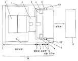
도 11 은 방전 가공기에 사용하는 일반적인 회전 테이블을 면판의 회전면의 수평 방향에서 본 경우의 단면도이다. 도 11 에 나타내는 바와 같이 회전 테이블 장치 (24) 의 케이싱 (1) 내부에는 동력부 (2) 나 감속기 (3) 이 있고, 케이싱 (1) 의 선단측에는 베어링 지지부 (7) 이 병설되고, 베어링부 (4) 는 베어링 지지부 (7) 에 의해 지지되고 있다. 베어링부 (4) 의 양측에는 샤프트 (5), 면판 (6) 이 고정되어 있고, 샤프트 (5) 와 면판 (6) 은 감속기 (3) 의 회전에 동기하여 자유롭게 회전할 수 있다. 베어링 지지부 (7) 의 근처에는 시일 기구부 (8) 이 있고, 시일 기구부 (8) 내부의 시일 장착 홈 (83) 에 시일재 (9) 가 수용되어 있다. 시일재 (9) 는 면판 (6) 의 외주면에 접촉함으로써, 시일 기구부 (8) 와 면판 (6) 의 간극 (11) 으로부터의 가공액이 케이싱 (1) 내부로 침입하는 것을 방지하고 있다.11 is a cross-sectional view of a general rotary table used in an electric discharge machining apparatus when viewed from a horizontal direction of a rotating surface of a face plate. 11, a
상기와 같은 시일 부재를 구비한 회전 테이블에 관한 종래 기술로서, 예를 들어 일본 공개특허공보 2005-118915호에는 방전 가공에 사용하는 회전축에 있어서, 회전축 보디와 회전 테이블 사이에 설치하는 시일재와 집전장치의 설치 구조가 개시되어 있다. 또, 일본 공개특허공보 2011-104725호에는 시일재를 사용하여 축봉을 실시하는 회전축에 있어서, 고압 에어를 보디와 회전 테이블 사이의 시일 부위로 공급하고, 시일 부위로부터의 고압 에어가 보디와 에어 시일링의 간극을 지나 회전 테이블의 외측으로 빠져나감으로써, 이 간극으로부터의 이물질의 침입을 방지하는 것을 특징으로 한 기술이 개시되어 있다.Japanese Unexamined Patent Application Publication No. 2005-118915 discloses a rotary shaft used for electric discharge machining. For example, Japanese Unexamined Patent Publication (Kokai) No. 2005-118915 discloses a rotary shaft having the above- The installation structure of the device is disclosed. Japanese Laid-Open Patent Publication No. 2011-104725 discloses a rotary shaft for performing a shaft rod using a sealing material, in which high-pressure air is supplied to a seal portion between a body and a rotary table, And then escapes to the outside of the rotary table through the clearance of the ring, thereby preventing the foreign matter from intruding from the clearance.
방전 가공기에 의한 가공중에는 슬러지라고 불리는 가공 부스러기가 발생하여 가공액 속에 부유하고 있다. 슬러지를 함유한 가공액이 화살표 (18) 과 같이, 간극 (11) 에 침입해 오면, 시일재 (9) 와 면판 (6) 사이에 슬러지가 부착되어 시일재 (9) 의 조기 마모를 일으키게 된다. 시일재 (9) 가 마모되었을 경우, 가공액이 케이싱 (1) 내부까지 침입하여 동력부 (2) 나 감속기 (3) 의 파손으로 이어지게 하기 때문에, 시일재 (9) 를 교환해야 한다.During processing by the electric discharge machine, processing debris called sludge is generated and floating in the processing liquid. Sludge adheres between the sealing
그러나, 도 11 에 나타낸 회전 테이블 장치 (24) 나 특허문헌 1, 2 에 나타낸 회전 테이블 장치의 경우, 시일 기구부가 일체로 구성되어 있기 때문에, 도 12 에 나타내는 바와 같이 면판 (6) 을 떼어내지 않으면, 도 13 에 나타내는 바와 같이 마모된 시일재 (9) 를 교환할 수 없다는 과제가 있었다. 또, 시일재 (9) 를 교환하여 장착한 후에는 면판 (6) 을 장착하여 회전 흔들림이나 면판의 평면도 등을 재조정할 필요가 있어, 시일재의 교환 작업 이외의 공정수가 들게 된다는 과제가 있었다.However, in the case of the
따라서 본 발명의 목적은 시일재의 교환을 단시간에 간단하게 실시할 수 있게 한 방전 가공기에 사용되는 회전 테이블을 제공하는 것이다.SUMMARY OF THE INVENTION It is therefore an object of the present invention to provide a rotary table used in an electric discharge machine in which replacement of a sealing material can be carried out simply in a short time.
본 발명에 의한 회전 테이블 장치는 케이싱과, 그 케이싱에 축지지되어 회전하는 면판과, 그 면판을 회전시키기 위한 구동부를 구비한 것으로서, 상기 케이싱과 상기 면판 사이에 배치 형성되는 시일재와, 상기 시일재를 유지하기 위한 상기 케이싱의 단부에 형성된 케이싱측 시일 장착 홈을 형성하는 케이싱측 홈 형성부와, 상기 시일재를 누르는 시일 누름 부분을 구비한 시일 기구부를 구비하고, 상기 케이싱측 홈 형성부를 갖는 부분과, 상기 시일 누름 부분은 분리할 수 있게 구성되어 있는 것을 특징으로 한다.A rotary table apparatus according to the present invention includes a casing, a face plate that is pivotally supported by the casing and rotates, and a driving unit for rotating the face plate. The rotary table apparatus includes a seal member disposed between the casing and the face plate, And a sealing mechanism portion having a casing side groove forming portion for forming a casing side seal mounting groove formed at an end portion of the casing for holding the ash and a seal pressing portion for pressing the sealing material, And the seal pressing portion are configured to be separable from each other.
상기 회전 테이블 장치는 상기 케이싱측 홈 형성부에 있어서의 상기 시일 누름 부분측의 적어도 일부가 절결되어 있는 것을 특징으로 한다.The rotary table device is characterized in that at least a part of the seal-pressing portion side of the casing-side groove forming portion is cut away.
상기 회전 테이블 장치는 상기 시일 누름 부분에 상기 시일재를 장착하기 위한 누름측 시일 장착 홈을 형성하는 누름측 홈 형성부를 가지고, 상기 시일재는 상기 케이싱측 홈 형성부와, 상기 누름측 홈 형성부에 의해 유지되는 것을 특징으로 한다.Wherein the rotary table device has a press side groove forming portion for forming a press side seal mounting groove for mounting the seal material on the seal press portion, the seal material has a groove portion formed in the casing side groove forming portion and the press side groove forming portion .
상기 회전 테이블 장치는 상기 케이싱측 홈 형성부를 가진 부분과, 상기 시일 누름 부분을 분리했을 때에 외부로부터 관측 가능한 상기 시일재의 에지 부분의 적어도 하나에 돌기 형상을 갖는 것을 특징으로 한다.The rotary table device has a protruding shape in at least one of a portion having the casing side groove forming portion and an edge portion of the seal material which can be observed from the outside when the seal pressing portion is separated.
본 발명에 의한 방전 가공기는 가공 대상물을 장착하는 회전 테이블 장치로서 상기 회전 테이블 장치의 어느 하나를 사용하고, 그 회전 테이블 장치를 제어하여 방전 가공을 행하는 제어장치를 구비하는 것을 특징으로 한다.The electric discharge machine according to the present invention is characterized in that a rotary table apparatus for mounting an object to be processed is provided with a control apparatus which uses any one of the rotary table apparatuses and controls the rotary table apparatus to perform electric discharge machining.
본 발명에 의한 시일 기구는 케이싱과, 그 케이싱에 축지지되어 회전하는 면판과, 그 면판을 회전시키기 위한 구동부를 구비한 회전 테이블 장치에 사용되는 시일 기구에 있어서, 상기 케이싱과 상기 면판 사이에 배치 형성되는 시일재와, 상기 시일재를 유지하기 위한 상기 케이싱의 단부에 형성된 케이싱측 시일 장착 홈을 형성하는 케이싱측 홈 형성부와, 상기 시일재를 누르는 시일 누름 부분을 구비하고, 상기 케이싱측 홈 형성부를 가진 부분과, 상기 시일 누름 부분과는 분리할 수 있게 구성되어 있는 것을 특징으로 한다.A sealing mechanism according to the present invention is a sealing mechanism used in a rotary table apparatus having a casing, a face plate that is pivotally supported by the casing and rotates, and a drive unit for rotating the face plate, the seal mechanism being disposed between the casing and the face plate A casing side groove forming portion for forming a casing side seal mounting groove formed in an end portion of the casing for holding the sealing material and a seal pressing portion for pressing the sealing material, And the seal pressing portion is configured to be separable from the portion having the forming portion.
본 발명의 방전 가공기에 사용하는 회전 테이블에서는 시일재의 교환을 단시간에 간단하게 실시할 수 있게 되고, 종래 기술에 있어서의 회전 테이블과 비교하여 시일재의 교환 작업의 공정수를 줄일 수 있다.In the rotary table used in the electric discharge machine of the present invention, the replacement of the sealing material can be easily performed in a short period of time, and the number of steps of replacing the sealing material can be reduced as compared with the rotary table in the related art.
본 발명의 상기한 및 그 밖의 목적 및 특징은 첨부 도면을 참조한 이하의 실시예의 설명으로부터 분명해질 것이다. 그 도면들 중 :
도 1 은 본 발명의 제 1 실시형태에 의한 회전 테이블 장치의 단면도이다.
도 2 는 도 1 의 회전 테이블 장치에 있어서의 시일 누름판을 떼어낸 상태를 나타내는 도면이다.
도 3 은 도 2 의 회전 테이블 장치에 있어서의 시일재를 떼어낸 상태를 나타내는 도면이다.
도 4 는 본 발명의 제 2 실시형태에 의한 회전 테이블 장치의 단면도이다.
도 5 는 도 4 의 회전 테이블 장치에 있어서의 시일 누름판을 떼어낸 상태를 나타내는 도면이다.
도 6 은 도 5 의 회전 테이블 장치에 있어서의 시일재를 떼어낸 상태를 나타내는 도면이다.
도 7 은 본 발명의 제 3 실시형태에 의한 회전 테이블 장치의 단면도이다.
도 8 은 도 7 의 회전 테이블 장치에 있어서의 시일 누름판을 떼어낸 상태를 나타내는 도면이다.
도 9 는 본 발명의 다른 실시형태에 의한 회전 테이블 장치의 단면도이다.
도 10 은 본 발명의 회전 테이블 장치를 사용한 방전 가공기의 개략 구성도이다.
도 11 은 종래 기술에 의한 회전 테이블 장치의 단면도이다.
도 12 는 도 11 의 회전 테이블 장치에 있어서 면판을 떼어낸 상태를 나타내는 도면이다.
도 13 은 도 12 의 회전 테이블 장치에 있어서 시일재를 떼어낸 상태를 나타내는 도면이다.The above and other objects and features of the present invention will become apparent from the following description of the embodiments with reference to the accompanying drawings. Of these drawings:
1 is a sectional view of a rotary table apparatus according to a first embodiment of the present invention.
Fig. 2 is a view showing a state in which the seal press plate is removed in the rotary table apparatus of Fig. 1. Fig.
Fig. 3 is a view showing a state in which the seal material is removed from the rotary table apparatus of Fig. 2;
4 is a sectional view of a rotary table apparatus according to a second embodiment of the present invention.
Fig. 5 is a view showing a state in which a seal press plate is removed from the rotary table apparatus of Fig. 4;
Fig. 6 is a view showing a state in which the seal material is removed from the rotary table apparatus of Fig. 5;
7 is a sectional view of a rotary table apparatus according to a third embodiment of the present invention.
8 is a view showing a state in which the seal pressing plate is removed in the rotary table apparatus of Fig.
9 is a sectional view of a rotary table apparatus according to another embodiment of the present invention.
10 is a schematic configuration diagram of an electric discharge machine using the rotary table apparatus of the present invention.
11 is a cross-sectional view of a conventional rotary table apparatus.
12 is a view showing a state in which a face plate is removed in the rotary table apparatus of Fig.
13 is a view showing a state in which the sealing material is removed in the rotary table apparatus of Fig.
이하, 본 발명의 실시형태를 도면과 함께 설명한다. 또한, 종래 기술과 동일 또는 유사한 구성은 같은 부호를 사용하여 설명한다.BRIEF DESCRIPTION OF THE DRAWINGS Fig. The same or similar components as those of the prior art will be described using the same reference numerals.
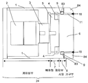
도 1 은 본 발명의 제 1 실시형태에 있어서의 회전 테이블 장치를 면판의 회전면의 수평 방향에서 본 경우에 있어서의 단면도이다. 본 실시 형태의 회전 테이블 장치 (24) 는 종래 기술의 회전 테이블 장치 (24) 와 마찬가지로, 케이싱 (1) 의 내부에, 동력부 (2) 나 감속기 (3) 을 구비하고 있고, 케이싱 (1) 의 선단측에는 베어링 지지부 (7) 이 병설되어 있다. 또, 베어링부 (4) 는 베어링 지지부 (7) 에 의해 지지되고 있고, 베어링부 (4) 의 양측에는 샤프트 (5), 면판 (6) 이 고정되고, 샤프트 (5) 와 면판 (6) 은 감속기 (3) 의 회전에 동기하여 자유롭게 회전할 수 있다. 베어링 지지부 (7) 근처에는 시일 기구부 (8) 이 있고, 케이싱 (1) 선단의 내원주부에 형성된 시일 장착 홈 (83) 과 시일 누름판 (84) 사이에 시일재 (9) 가 수용되어 있다. 케이싱 (1) 과 시일 누름판 (84) 은 분리할 수 있게 구성되어 있다. 시일 누름판 (84) 는 나사 등에 의해 케이싱 (1) 의 선단에 장착하도록 해도 되고, 케이싱 (1) 의 선단부와 시일 누름판 (84) 에 서로 끼워맞춤하는 장착 기구 등을 설치하여 장착하도록 해도 된다.1 is a cross-sectional view of a rotary table apparatus according to a first embodiment of the present invention when viewed in a horizontal direction of a rotating surface of a face plate. The
도 2 는 도 1 에 나타낸 회전 테이블 장치 (24) 로부터 시일 누름판 (84) 를 떼어낸 상태를 나타내고 있고, 또 도 3 은 도 2 상태에서 시일재 (9) 를 떼어낸 상태를 나타내고 있다.Fig. 2 shows a state in which the
도 2 에 나타내는 바와 같이, 본 실시 형태의 회전 테이블 장치 (24) 에서는 시일 누름판 (84) 를 떼어냄으로써, 면판 (6) 을 움직이거나 또는 떼어내지 않고 시일 장착 홈 (83) 에 수용되어 있는 시일재 (9) 를 그 시일재 (9) 의 외주면 (94) 를 파지하여 인발할 수 있다. 그 때문에, 면판 (6) 의 떼어냄이나, 시일재 (9) 의 교환 작업 후의 면판 (6) 의 재장착, 및 회전 흔들림이나 면판의 평면도 등의 재조정 작업이 불필요해져, 시일재 (9) 의 교환 작업의 공정수를 줄일 수 있다. 또, 시일 장착 홈 (83) 에는 고무나 스프링, 웨이브 와셔 등을 사용하여 시일을 밀어내는 것 같은 기구를 설치해도 된다.2, in the
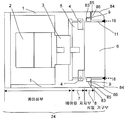
도 4 는 본 발명의 제 2 실시형태에 있어서의 회전 테이블 장치를 면판의 회전면의 수평 방향에서 본 경우에 있어서의 단면도이다. 제 1 실시형태에 의한 회전 테이블 장치 (24) 에서는 시일 기구부 (8) 에 있어서의 케이싱 (1) 의 전면 (85) 과 시일재 (9) 의 측면 (92) 가 면일 (두 개의 면 사이에 단차가 없이 플랫한 상태) 하게 되는 구조로 되어 있었지만, 본 실시 형태에 의한 회전 테이블 장치 (24) 에서는 시일 장착 홈 (83) 에 절결 (86) 을 형성한 구조로 되어 있다.4 is a cross-sectional view of the rotating table apparatus according to the second embodiment of the present invention when viewed in the horizontal direction of the rotating face of the face plate. In the
도 5 는 도 4 에 나타낸 회전 테이블 장치 (24) 로부터 시일 누름판 (84) 를 떼어낸 상태를 나타내고 있고, 또 도 6 은 도 5 상태에서 시일재 (9) 를 떼어낸 상태를 나타내고 있다.Fig. 5 shows a state in which the
도 5 에 나타내는 바와 같이, 본 실시 형태의 회전 테이블 장치 (24) 에서는 시일 누름판 (84) 를 떼어냈을 때에, 케이싱 (1) 에 형성된 절결 (86) 부분에 시일재 (9) 의 외주면 (94) 중의 에지 부분 (93) 이 돌출되도록 되어 있기 때문에, 시일재 (9) 의 에지 부분 (93) 을 공구 등으로 확실하게 잡을 수 있다. 이로써, 제 1 실시형태와 비교하여 더욱 간단하게 시일재 (9) 를 교환할 수 있다. 또, 적절한 공구 등이 없어도, 바늘과 같은 선단이 날카로운 것을, 시일 장착 홈 (83) 의 내주면에 접촉시키지 않고, 에지 부분 (93) 에만 걸 수 있기 때문에, 도 6 에 나타내는 시일 장착 홈 (83) 의 내주면 (88) 에 잘못하여 흠집이 생기게 하는 것을 방지할 수 있다. 또한, 시일 장착 홈 (83) 에 있는 절결 (86) 은 전체 둘레 또는 원주부의 일부라도 좋다.5, in the
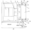
도 7 은 본 발명의 제 3 실시형태에 의한 회전 테이블 장치를 면판의 회전면의 수평 방향에서 본 경우에 있어서의 단면도이다. 본 실시 형태에 의한 회전 테이블 장치 (24) 에서는 시일 장착 홈 (83) 의 깊이가 시일재 (9) 의 폭보다 얕게 되어 있고, 시일 장착 홈 (83) 에서 튀어나온 시일재 (9) 는 시일 누름판 (84) 에 형성된 시일 장착 홈 (87) 에 수용되도록 되어 있다. 이와 같은 구조로 함으로써, 시일재 (9) 를 유지할 수 있음과 함께, 도 8 에 나타내는 바와 같이, 시일 누름판 (84) 를 떼어냈을 때에는 시일재 (9) 의 에지 부분 (93) 이 외부로부터 용이하게 확인할 수 있도록 되어 있기 때문에, 제 1, 제 2 실시형태에 의한 회전 테이블 장치 (24) 와 마찬가지로 시일재 (9) 를 용이하게 떼어낼 수 있다.7 is a cross-sectional view of the rotary table apparatus according to the third embodiment of the present invention when viewed in the horizontal direction of the rotating face of the face plate. In the
또한, 시일재 (9) 의 외주면 (94) 중의 에지 부분 (93) 은 사각만이 아니고, 도 9 에 나타내는 바와 같이 미리 공구로 잡기 쉽거나, 또는 걸리기 쉬운 형상으로 해 두어도 된다.The
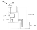
도 10 은 본 발명에 의한 회전 테이블 장치 (24) 를 탑재한 방전 가공기의 개략 구성도이다. 방전 가공기 (100) 에 사용하는 회전 테이블 장치 (24) 는 가공액 공급 수단 (25) 로부터 공급되는 가공액으로 채워진 가공조 (21) 내에 있는 워크 테이블에 면판 (6) 이 수직 (상측) 이 되도록, 또는 수평 (측면) 을 향하도록 설치하고, 면판 (6) 에 가공물을 고정시켜 사용한다.10 is a schematic configuration diagram of an electric discharge machine equipped with a
방전 가공기 (100) 에서는 제어 장치 (20) 의 제어하에서 방전 가공이 행해지는데, 그 방전 가공에 있어서는 워크가 설치되는 회전 테이블 장치 (24) 의 동력부 (2) 나 감속기 (3) 도 역시, 제어 장치 (20) 로부터의 지령에 의해 그 동작이 제어된다. 가공중에 발생한 슬러지 (가는 금속 분말) 등이 포함되는 가공액은 오수조 (22) 로 배출되고, 필터 등에 의해 깨끗하게 한 다음에 가공액 공급 수단 (25) 에 의해 가공조 (21) 로 공급된다. 본 발명의 회전 테이블 장치 (24) 에서는 시일 기구부 (8) 에 의해 슬러지 등이 케이싱 (1) 의 내부로 침입하는 것을 방지할 수 있고, 또, 시일 누름판 (84) 를 떼어냄으로써 시일재 (9) 를 간단하게 교환할 수 있다.In the electric
이상, 본 발명의 실시형태에 대해 설명했지만, 본 발명은 상기 서술한 실시형태의 예로만 한정되지 않고, 적절히 변경을 더함으로써 여러 가지 양태로 실시할 수 있다.Although the embodiments of the present invention have been described above, the present invention is not limited to the above-described embodiments, and various modifications can be made by appropriately changing the embodiments.
예를 들어, 시일재 (9) 의 재질은 탄력성이 있는 고무제의 O 링이나 오일 시일 뿐만 아니고, 수지제의 시일을 사용할 수 있는 경우가 있다.For example, the sealing
Claims (6)
상기 케이싱과 상기 면판 사이에 배치 형성되는 시일재와,
상기 시일재를 유지하기 위한 상기 케이싱의 단부에 형성된 케이싱측 시일 장착 홈을 형성하는 케이싱측 홈 형성부와,
상기 시일재를 누르는 시일 누름 부분을 구비한 시일 기구부를 구비하고,
상기 케이싱측 홈 형성부를 갖는 부분과, 상기 시일 누름 부분은 분리할 수 있게 구성되어 있는 것을 특징으로 하는 회전 테이블 장치.1. A rotary table apparatus comprising a casing, a face plate rotatably supported on the casing, and a drive unit for rotating the face plate,
A seal member disposed between the casing and the face plate,
A casing side groove forming portion for forming a casing side seal mounting groove formed in an end portion of the casing for holding the sealing material,
And a seal mechanism portion having a seal pressing portion for pressing the seal material,
Wherein the portion having the casing side groove forming portion and the seal pressing portion are configured to be separable.
상기 케이싱측 홈 형성부에 있어서의 상기 시일 누름 부분측의 적어도 일부가 절결되어 있는 것을 특징으로 하는 회전 테이블 장치.The method according to claim 1,
Wherein at least a part of the seal-side pressing portion side of the casing-side groove forming portion is cut away.
상기 시일 누름 부분에 상기 시일재를 장착하기 위한 누름측 시일 장착 홈을 형성하는 누름측 홈 형성부를 가지고,
상기 시일재는 상기 케이싱측 홈 형성부와, 상기 누름측 홈 형성부에 의해 유지되는 것을 특징으로 하는 회전 테이블 장치.The method according to claim 1,
And a press-side groove forming portion for forming a press-side seal mounting groove for mounting the sealing material on the seal pressing portion,
And the sealing material is held by the casing side groove forming portion and the pressing side groove forming portion.
상기 케이싱측 홈 형성부를 가진 부분과, 상기 시일 누름 부분을 분리했을 때에 외부로부터 관측 가능한 상기 시일재의 에지 부분의 적어도 하나에 돌기 형상을 갖는 것을 특징으로 하는 회전 테이블 장치.4. The method according to any one of claims 1 to 3,
Wherein at least one of the portion having the casing side groove forming portion and the edge portion of the seal member observable from the outside when the seal pressing portion is separated has a protruding shape.
그 회전 테이블 장치를 제어하여 방전 가공을 행하는 제어장치를 구비하는 것을 특징으로 하는 방전 가공기.A rotary table apparatus for mounting an object to be processed, comprising: the rotary table apparatus according to any one of claims 1 to 4;
And a control device for controlling the rotation table device to perform electric discharge machining.
상기 케이싱과 상기 면판 사이에 배치 형성되는 시일재와,
상기 시일재를 유지하기 위한 상기 케이싱의 단부에 형성된 케이싱측 시일 장착 홈을 형성하는 케이싱측 홈 형성부와,
상기 시일재를 누르는 시일 누름 부분을 구비하고,
상기 케이싱측 홈 형성부를 가진 부분과, 상기 시일 누름 부분과는 분리할 수 있게 구성되어 있는 것을 특징으로 하는 시일 기구.CLAIMS 1. A sealing mechanism used in a rotary table apparatus having a casing, a face plate rotatably supported by the casing, and a driving portion for rotating the face plate,
A seal member disposed between the casing and the face plate,
A casing side groove forming portion for forming a casing side seal mounting groove formed in an end portion of the casing for holding the sealing material,
And a seal pressing portion for pressing the sealing material,
Wherein the sealing portion is configured to be separated from the portion having the casing side groove forming portion and the seal pressing portion.
Applications Claiming Priority (2)
| Application Number | Priority Date | Filing Date | Title |
|---|---|---|---|
| JP2015229985A JP6370767B2 (en) | 2015-11-25 | 2015-11-25 | Rotary table device for electric discharge machine |
| JPJP-P-2015-229985 | 2015-11-25 |
Publications (2)
| Publication Number | Publication Date |
|---|---|
| KR20170061073A true KR20170061073A (en) | 2017-06-02 |
| KR101990670B1 KR101990670B1 (en) | 2019-06-18 |
Family
ID=57406075
Family Applications (1)
| Application Number | Title | Priority Date | Filing Date |
|---|---|---|---|
| KR1020160155645A KR101990670B1 (en) | 2015-11-25 | 2016-11-22 | Rotation table |
Country Status (5)
| Country | Link |
|---|---|
| US (1) | US10549370B2 (en) |
| EP (1) | EP3173174B1 (en) |
| JP (1) | JP6370767B2 (en) |
| KR (1) | KR101990670B1 (en) |
| CN (1) | CN106799524B (en) |
Cited By (1)
| Publication number | Priority date | Publication date | Assignee | Title |
|---|---|---|---|---|
| KR20200123781A (en) | 2018-02-27 | 2020-10-30 | 니폰 제온 가부시키가이샤 | Slurry composition for lithium ion secondary battery and electrode for lithium ion secondary battery |
Citations (5)
| Publication number | Priority date | Publication date | Assignee | Title |
|---|---|---|---|---|
| US4021049A (en) * | 1975-12-15 | 1977-05-03 | Caterpillar Tractor Co. | Adjustable lip type seal for a crankshaft |
| JP2005118915A (en) | 2003-10-14 | 2005-05-12 | Kitagawa Iron Works Co Ltd | Rotary table device for electrical discharge machining |
| JP2008272853A (en) * | 2007-04-26 | 2008-11-13 | Jtekt Corp | High acceleration rotary table device in machine tool |
| JP2011104725A (en) | 2009-11-18 | 2011-06-02 | Kitagawa Iron Works Co Ltd | Rotary table with air seal structure |
| JP2015048865A (en) * | 2013-08-30 | 2015-03-16 | 井上スダレ株式会社 | Pipe joint |
Family Cites Families (30)
| Publication number | Priority date | Publication date | Assignee | Title |
|---|---|---|---|---|
| GB1045489A (en) * | 1962-08-29 | 1966-10-12 | Standard Pressed Steel Co | Improvements in and relating to apparatus for electrochemical machining |
| GB1308563A (en) * | 1969-06-21 | 1973-02-21 | Olivetti & Co Spa | Machine tool with rotary work-table |
| DE2137698C3 (en) * | 1971-07-28 | 1983-11-03 | Fibro Gmbh, 7102 Weinsberg | Rotary indexing table with a fixed base body and a mounting plate arranged on it so that it can be rotated and angle-adjusted |
| US3772961A (en) * | 1972-04-06 | 1973-11-20 | Giddings & Lewis | Hydrostatic rotary table |
| US3975608A (en) * | 1972-04-06 | 1976-08-17 | A.G. Fur Industrielle Elektronik Agie Losone B. Locarno | Method and apparatus for regulating the gap distance in electroerosin machining |
| US3871665A (en) | 1973-04-09 | 1975-03-18 | Greene Tweed & Co Inc | Rod wiper assembly |
| US4076339A (en) * | 1977-01-19 | 1978-02-28 | National Automatic Tool Company, Inc. | Air bearing assembly for rotational table |
| US4337385A (en) * | 1977-05-11 | 1982-06-29 | Uti Corporation | Orbital tool support system for EDM machines and other machine tools |
| US4196908A (en) * | 1978-12-14 | 1980-04-08 | Canica Crushers, Ltd. | Seal for centrifugal impack rock crusher |
| US4881829A (en) * | 1986-06-30 | 1989-11-21 | Koelsch Lester M | Submersible bearing assembly |
| US4841126A (en) * | 1987-12-28 | 1989-06-20 | Mcwilliams Machinery Sales, Division Of Bridgeport Machines Inc. | Rotary table wire EDM machine |
| JP2906058B2 (en) * | 1988-08-23 | 1999-06-14 | 株式会社森精機製作所 | Machine tool table equipment |
| DE3835708A1 (en) | 1988-10-17 | 1990-04-19 | Mannesmann Ag | SHAFT SEAL |
| JPH0292117U (en) * | 1989-01-09 | 1990-07-23 | ||
| JP2573657Y2 (en) * | 1990-07-10 | 1998-06-04 | 日本精工株式会社 | Rotary axis clamping device |
| JP3554740B2 (en) * | 1995-10-03 | 2004-08-18 | 株式会社近藤製作所 | Dust prevention method for positioning error absorbing device |
| JP4503237B2 (en) * | 2003-04-04 | 2010-07-14 | 内山工業株式会社 | Combination seal and bearing unit |
| JP4320241B2 (en) * | 2003-11-07 | 2009-08-26 | 津田駒工業株式会社 | Index table |
| JP2008213098A (en) * | 2007-03-06 | 2008-09-18 | Mitsubishi Heavy Ind Ltd | Index table |
| CN103557331B (en) * | 2007-06-19 | 2016-05-04 | 株式会社开滋 | Use the drive unit of shaft seal mechanism |
| CN101158437B (en) | 2007-10-31 | 2010-05-19 | 天津市亚安科技电子有限公司 | Water-proof structure of outdoor horizontal stage rotational axis |
| CN101966615B (en) | 2010-09-30 | 2012-01-04 | 苏州电加工机床研究所有限公司 | External rotary index table for electrical process machine |
| JP5341969B2 (en) * | 2011-10-28 | 2013-11-13 | 株式会社日研工作所 | Brake structure of rotary table device |
| JP5684346B2 (en) * | 2013-08-26 | 2015-03-11 | ファナック株式会社 | Electric discharge machine with rotating shaft |
| JP5887376B2 (en) * | 2014-04-09 | 2016-03-16 | ファナック株式会社 | Electric discharge machine with rotating shaft |
| JP6280010B2 (en) * | 2014-09-25 | 2018-02-14 | ファナック株式会社 | Rotating shaft device and electric discharge machine equipped with the rotating shaft device |
| JP5960370B1 (en) * | 2015-02-24 | 2016-08-02 | ファナック株式会社 | Rotary table device |
| JP6505472B2 (en) * | 2015-03-03 | 2019-04-24 | 津田駒工業株式会社 | Rotary table device |
| JP6382869B2 (en) * | 2016-02-19 | 2018-08-29 | ファナック株式会社 | Rotary table device |
| DE102016207583A1 (en) * | 2016-05-03 | 2017-11-09 | Baumüller Holding GmbH & Co. KG | Container handling machine with a turntable direct drive |
-
2015
- 2015-11-25 JP JP2015229985A patent/JP6370767B2/en active Active
-
2016
- 2016-11-22 KR KR1020160155645A patent/KR101990670B1/en active IP Right Grant
- 2016-11-23 US US15/359,663 patent/US10549370B2/en active Active
- 2016-11-23 CN CN201611048600.0A patent/CN106799524B/en active Active
- 2016-11-24 EP EP16200402.2A patent/EP3173174B1/en active Active
Patent Citations (5)
| Publication number | Priority date | Publication date | Assignee | Title |
|---|---|---|---|---|
| US4021049A (en) * | 1975-12-15 | 1977-05-03 | Caterpillar Tractor Co. | Adjustable lip type seal for a crankshaft |
| JP2005118915A (en) | 2003-10-14 | 2005-05-12 | Kitagawa Iron Works Co Ltd | Rotary table device for electrical discharge machining |
| JP2008272853A (en) * | 2007-04-26 | 2008-11-13 | Jtekt Corp | High acceleration rotary table device in machine tool |
| JP2011104725A (en) | 2009-11-18 | 2011-06-02 | Kitagawa Iron Works Co Ltd | Rotary table with air seal structure |
| JP2015048865A (en) * | 2013-08-30 | 2015-03-16 | 井上スダレ株式会社 | Pipe joint |
Cited By (1)
| Publication number | Priority date | Publication date | Assignee | Title |
|---|---|---|---|---|
| KR20200123781A (en) | 2018-02-27 | 2020-10-30 | 니폰 제온 가부시키가이샤 | Slurry composition for lithium ion secondary battery and electrode for lithium ion secondary battery |
Also Published As
| Publication number | Publication date |
|---|---|
| CN106799524A (en) | 2017-06-06 |
| JP2017094456A (en) | 2017-06-01 |
| US20170144240A1 (en) | 2017-05-25 |
| JP6370767B2 (en) | 2018-08-08 |
| CN106799524B (en) | 2019-07-19 |
| EP3173174A1 (en) | 2017-05-31 |
| EP3173174B1 (en) | 2020-06-24 |
| KR101990670B1 (en) | 2019-06-18 |
| US10549370B2 (en) | 2020-02-04 |
Similar Documents
| Publication | Publication Date | Title |
|---|---|---|
| CN104325402B (en) | Cutting apparatus | |
| EP3009219B1 (en) | Rotary table apparatus and electric discharge machine using the rotary table apparatus | |
| JP2011104725A (en) | Rotary table with air seal structure | |
| KR101990670B1 (en) | Rotation table | |
| KR101759772B1 (en) | Processing equipment | |
| JP5200477B2 (en) | Extruder | |
| EP3105008A1 (en) | Apparatus for working elements made of stone-like material, ceramic material, stone-resinoid agglomerate, glass and/or quartz-resinoid agglomerate and derivatives thereof or the like, even with high hardness | |
| JP2007268630A (en) | Roll polisher and roll polishing method | |
| TW202023743A (en) | Coolant processing device | |
| KR101754113B1 (en) | Retapping apparatus | |
| KR102522352B1 (en) | magnet separator | |
| JP2009254989A (en) | Cleaning device and cleaning method | |
| JP2010029963A (en) | Steel pipe end finishing machine | |
| KR101809195B1 (en) | the splitting machine using the cam | |
| JP6633594B2 (en) | Rotating shaft device and electric discharge machine equipped with the rotating shaft device | |
| KR102415615B1 (en) | Metal piece auto polishing apparatus including multi polishing stage | |
| US3570037A (en) | Shaft wiper | |
| JP2010064207A (en) | Working fluid supply device | |
| KR102096803B1 (en) | A Shaft Face Milling Apparatus | |
| CN207272911U (en) | A kind of roller brush play burring mechanism | |
| JP5434468B2 (en) | Processing fluid supply device | |
| KR101780442B1 (en) | Drilling device for processing eyeglass lens | |
| KR20190136676A (en) | Filtering device of cutting tool | |
| CN104963266A (en) | Efficient road construction device | |
| KR20040057463A (en) | Choke fixing device for manufacturing cold steel plate |
Legal Events
| Date | Code | Title | Description |
|---|---|---|---|
| A201 | Request for examination | ||
| A302 | Request for accelerated examination | ||
| E902 | Notification of reason for refusal | ||
| E701 | Decision to grant or registration of patent right | ||
| GRNT | Written decision to grant |