KR20170059256A - Electric Furnace - Google Patents
Electric Furnace Download PDFInfo
- Publication number
- KR20170059256A KR20170059256A KR1020150163386A KR20150163386A KR20170059256A KR 20170059256 A KR20170059256 A KR 20170059256A KR 1020150163386 A KR1020150163386 A KR 1020150163386A KR 20150163386 A KR20150163386 A KR 20150163386A KR 20170059256 A KR20170059256 A KR 20170059256A
- Authority
- KR
- South Korea
- Prior art keywords
- crucible
- vibrator
- melting furnace
- electric melting
- molten metal
- Prior art date
Links
Images


Classifications
-
- B—PERFORMING OPERATIONS; TRANSPORTING
- B22—CASTING; POWDER METALLURGY
- B22D—CASTING OF METALS; CASTING OF OTHER SUBSTANCES BY THE SAME PROCESSES OR DEVICES
- B22D17/00—Pressure die casting or injection die casting, i.e. casting in which the metal is forced into a mould under high pressure
- B22D17/20—Accessories: Details
- B22D17/28—Melting pots
-
- F—MECHANICAL ENGINEERING; LIGHTING; HEATING; WEAPONS; BLASTING
- F27—FURNACES; KILNS; OVENS; RETORTS
- F27B—FURNACES, KILNS, OVENS, OR RETORTS IN GENERAL; OPEN SINTERING OR LIKE APPARATUS
- F27B14/00—Crucible or pot furnaces
- F27B14/06—Crucible or pot furnaces heated electrically, e.g. induction crucible furnaces with or without any other source of heat
-
- F—MECHANICAL ENGINEERING; LIGHTING; HEATING; WEAPONS; BLASTING
- F27—FURNACES; KILNS; OVENS; RETORTS
- F27B—FURNACES, KILNS, OVENS, OR RETORTS IN GENERAL; OPEN SINTERING OR LIKE APPARATUS
- F27B14/00—Crucible or pot furnaces
- F27B14/08—Details peculiar to crucible or pot furnaces
-
- F—MECHANICAL ENGINEERING; LIGHTING; HEATING; WEAPONS; BLASTING
- F27—FURNACES; KILNS; OVENS; RETORTS
- F27D—DETAILS OR ACCESSORIES OF FURNACES, KILNS, OVENS, OR RETORTS, IN SO FAR AS THEY ARE OF KINDS OCCURRING IN MORE THAN ONE KIND OF FURNACE
- F27D27/00—Stirring devices for molten material
Landscapes
- Engineering & Computer Science (AREA)
- Mechanical Engineering (AREA)
- General Engineering & Computer Science (AREA)
- Crucibles And Fluidized-Bed Furnaces (AREA)
Abstract
Description
BACKGROUND OF THE
Generally, a metal melting furnace having a relatively small melting capacity includes a crucible, a reflection furnace, an electric furnace, and the crucible can be variously divided into an electric melting furnace, a high frequency induction heating furnace, and a heavy oil furnace have.
1 is a sectional view for explaining an electric melting furnace for a conventional crucible.
1, a crucible 12 is placed on a crucible base 11a at the lower center of a conventional furnace and a
As a conventional method of producing an aluminum forgings, a material is obtained by subjecting an extruded material or an aluminum continuous casting agent after homogenizing an aluminum casting agent to hot forging. Such a method can obtain a product with high reliability, There is a problem that the number of steps to completion of the final finished forged product is high and investment of expensive equipment is not only required but also the shape is limited to a simple shape so that the productivity is low and the manufacturing cost is high and the product is very competitive.
Accordingly, attempts have been made to manufacture various industrial products and automobile parts by dai casting in order to compensate for the disadvantages of the forging method. The die casting presses the molten metal at a high temperature under a high pressure, A high-pressure casting method capable of mass-producing a casting with a high degree of mechanical strength in a short period of time.
However, such a die casting has a problem in that it is not easy to apply to an aluminum alloy because of the remarkable difference in quality due to casting conditions, compared with excellent productivity.
That is, since the molten metal is filled at a high speed and high pressure, the pressure resistance is reduced due to the excessive amount of the contained gas, and the molten metal is first solidified by the molten metal in the casting, .
Defects in these pores or shrinkage holes not only reduce the strength of the final product, but also serve as obstacles to subsequent heat treatment and welding.
There have been known a number of methods for controlling pores and shrinkage holes in diecasting, such as vacuum die casting and pore-free die casting.
The vacuum die casting is a method for preventing the mixing of air by keeping the cavity provided in the die casting mold in a vacuum state. The unstretched die casting is a method in which the oxygen, for example, aluminum The same molten metal is allowed to react with each other to form an oxide protective film, thereby suppressing the incorporation of air and obtaining a dense casting free from pores.
However, even when the vacuum die casting and the non-porous die casting are performed, if the bubbles existing in the molten metal can not be removed, the produced product becomes brittleness, and defective products are produced.
Accordingly, a method of previously removing bubbles in a molten metal contained in a crucible (which means a container containing molten metal) before injecting the molten metal into the cavity provided in the die casting mold, and then injecting the molten metal into the cavity may also be used.
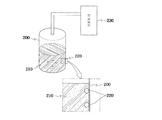
2 shows an apparatus for removing
However, even if the
Accordingly, the present invention has been made to solve the general problems of the conventional electric melting furnace,
A problem to be solved by the present invention is to provide an electric melting furnace having a vibrating crucible base which is provided with a vibrating means in a crucible base so that gases or impurities present in the melt can be easily extracted to the outside of the melt by vibrating the crucible have.
Another problem to be solved by the present invention is to provide an electric melting furnace having a vibrating crucible base for improving the structure of the crucible base so as to minimize the deformation of the crucible by vibration by the vibrating means.
As a concrete means of the present invention for solving the above-mentioned problems,
There is provided an electric melting furnace in which a crucible base and a crucible that is seated on an upper portion of the crucible base are installed in the main body,
Characterized in that a mounting portion for installing a vibrator as a vibrating means is provided in the crucible support, wherein the vibrator surrounds the outside thereof with a heat insulating member, and a strength reinforcing member is integrally provided inside the crucible holder in the crucible holder And an electric melting furnace having a pedestal.
As a preferred embodiment, the mounting portion is formed in a groove shape on the lower surface of the crucible support for accommodating the vibrator in the form of a rod, and the heat insulating member is formed as a rod for receiving the vibrator in the form of a rod The strength reinforcing member may include a plurality of metal bars or a plurality of metal mesh nets arranged in the interior of the crucible support.
As described above, the electric melting furnace provided with the vibratory crucible support according to the present invention has the effect that the vibrator as the vibrating means is provided in the crucible base and the crucible is vibrated so that gases or impurities existing in the molten metal can be easily extracted to the outside of the molten metal have. Further, since the crucible base of the present invention includes the strength reinforcing member, there is an advantage that the morphological deformation can be minimized even by vibration by the vibrator which is the vibration means.
1 is a sectional view for explaining an electric melting furnace for a conventional crucible.
Fig. 2 is a schematic view for explaining a conventional bubble removing device for molten metal.
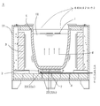
3 is a cross-sectional view illustrating an electric melting furnace having a vibrating crucible support according to the present invention.
4 is a perspective view for explaining a crucible support in an electric melting furnace having a vibrating crucible support according to the present invention.
5 is a view illustrating a vibrator and a heat insulating member in an electric melting furnace having a vibrating crucible support according to the present invention.
6 is a cross-sectional view for explaining an operating state of an electric melting furnace having a vibrating crucible support according to the present invention.
7 is a cross-sectional view for explaining another example of the installation of a vibrator in an electric melting furnace having a vibrating crucible base according to the present invention.
Hereinafter, preferred embodiments of the present invention will be described in detail with reference to the accompanying drawings.
3, the
Here, the
On the other hand, the
Here, in the present invention, a mounting portion 21 for mounting a vibrator (7: VIBRATOR) as a vibration means is provided in the crucible support. The mounting portion 21 is formed in a groove shape on the lower surface of the
At this time, it is preferable to wrap the outside of the vibrator (7) with a heat insulating member (8) so as to protect the vibrator (7) in a high temperature environment generated inside the main body (11) For example, a ceramic material or a metallic material having a high melting point (for example, sus (cushion)) or the like as a constituent material, in the form of a rod for receiving the vibrator (including a power supply wire) Structure, and extends to the outside of the
A
Hereinafter, an operation state of the electric melting furnace having the oscillating type crucible support according to the present invention will be described.
First, the quality of the molten metal is generally evaluated as (1) chemical composition, (2) gas, (3) inclusions, and (4) temperature.
① Chemical components are mainly determined by Si, Cu, Mg, Fe, etc. of the current gold or return material to be used. In addition, adjustment of minor components such as Na and Sr for improving processing, , Or addition adjustment of Ti, Ti-B or the like for making crystals finer becomes important. Moreover, since a trace amount of components influences, it is the most important task to match the desired components.
② Gas is hydrogen gas, etc. It means that the water contained in the atmosphere reacts with the molten aluminum and is absorbed in the form of hydrogen atoms in the molten metal. In a high-temperature molten metal, many hydrogen atoms are dissolved, but when the temperature is lowered to solidify to become solid, the amount thereof becomes extremely small. For this reason, hydrogen atoms become bubbles as molecules during the solidification process. The bubbles are trapped in the casting and become gas defects. These significantly reduce the mechanical properties, especially the elongation properties, the impact value, and the fatigue strength. For this reason, it is generally necessary to thoroughly remove the gas in the molten metal.
③ There are many kinds of inclusions such as oxides, but the most common inclusions are aluminum oxide films. The molten aluminum readily reacts with oxygen in the atmosphere to form aluminum oxide, which initially covers the molten bath surface as an extremely thin film. The thickness increases over time. Since the aluminum molten metal is light in specific gravity and has a small specific gravity difference with the oxide film, it is easily mixed with the molten metal and is difficult to separate. When this is mixed, not only deteriorates the mechanical properties like gas but also inhibits the flow of the molten metal to increase the occurrence of defects. Unlike gas, it is harmful regardless of the cooling rate, so thorough removal is required for all castings, including die castings.
④ Temperature is the most important factor for all processes of casting. If the temperature is inadequate even if the conditions (1) to (3) are satisfied, it can not be said that the quality of the melt is good.
Accordingly, the processing of the molten metal can be said to be a processing for completing the molten metal that can be obtained by melting the raw materials such as ground metal and return material at the highest quality. In general, the components and the temperatures (① and ④) are general, so they are focused on gas and oxide films (② and ③) It often means an inclusion. Specifically, there are many methods that are generally used at present, such as a treatment in a molten bath to a storage furnace or a treatment in a holding furnace.
Therefore, the
At this time, it is preferable that the vibration by the vibrator (7: VIBRATOR) adjusts the vibration force within a range in which the crucible (4) vulnerable to an external force is not damaged, and the crucible base (2) It is possible to prevent a phenomenon that the vibration is caused by the vibration of the vibrator 7 (VIBRATOR).
Meanwhile, in the present invention, a vibrator (7 ': VIBRATOR) as a vibrating means may be installed on the refractory layer 3' constituting the inner bottom surface of the main body on which the crucible support is installed, for example, refractory bricks. At this time, a vibrator (7 ': VIBRATOR) can be installed by providing a groove type mounting portion or a through-hole type mounting portion on the refractory brick. According to this configuration, the vibration of the vibrator 7 'installed in the refractory layer 3' is indirectly transmitted to the
It should be noted that the above-described embodiments are only illustrative and are not intended to limit the scope of the present invention so that those skilled in the art can readily understand and carry out the present invention. Accordingly, it should be noted that various modifications and changes may be made to the above-described embodiments. The scope of the present invention is defined by the following claims in principle.
1: electric melting furnace 2: crucible base
3, 3 ': refractory layer 4: crucible
5: electric heater 6: cover
7, 7 ': vibrator 8: insulating member
11: main body 21, 21 ': mounting portion
22:
22b: metal mesh net 41: molten metal
g: gas i: inclusion
Claims (2)
Characterized in that a mounting portion for installing a vibrator as a vibrating means is provided in the crucible support, wherein the vibrator surrounds the outside thereof with a heat insulating member, and a strength reinforcing member is integrally provided inside the crucible holder in the crucible holder An electric melting furnace with a pedestal.
Wherein the mounting portion is formed in a groove shape on the lower surface of the crucible support for accommodating the vibrator in the form of a rod, the heat insulating member is in the form of a rod for receiving the vibrator in the form of a rod, Characterized in that the crucible holder comprises a plurality of metal bars or a plurality of metal mesh nets arranged in the crucible support.
Priority Applications (1)
| Application Number | Priority Date | Filing Date | Title |
|---|---|---|---|
| KR1020150163386A KR20170059256A (en) | 2015-11-20 | 2015-11-20 | Electric Furnace |
Applications Claiming Priority (1)
| Application Number | Priority Date | Filing Date | Title |
|---|---|---|---|
| KR1020150163386A KR20170059256A (en) | 2015-11-20 | 2015-11-20 | Electric Furnace |
Publications (1)
| Publication Number | Publication Date |
|---|---|
| KR20170059256A true KR20170059256A (en) | 2017-05-30 |
Family
ID=59053032
Family Applications (1)
| Application Number | Title | Priority Date | Filing Date |
|---|---|---|---|
| KR1020150163386A KR20170059256A (en) | 2015-11-20 | 2015-11-20 | Electric Furnace |
Country Status (1)
| Country | Link |
|---|---|
| KR (1) | KR20170059256A (en) |
-
2015
- 2015-11-20 KR KR1020150163386A patent/KR20170059256A/en not_active Application Discontinuation
Similar Documents
| Publication | Publication Date | Title |
|---|---|---|
| CN110983262B (en) | Preparation method of aluminum-scandium alloy target material | |
| CN110144472B (en) | Vacuum induction melting method of manganese-copper vibration-damping alloy | |
| CN105436437B (en) | For forming the machine of metal bar | |
| CN110284030B (en) | Ultrasonic-assisted casting device and method for manufacturing aluminum-lithium alloy | |
| US7134477B2 (en) | Lightweight part, as well as process and device for its production | |
| US944370A (en) | Process and apparatus for making metal ingots. | |
| KR102528758B1 (en) | Die casting method of filter cavity | |
| CN101234420A (en) | Ultrasound wave compression mold casting method and special-purpose equipment thereof | |
| JP2007216239A (en) | Casting method | |
| GB2516990A (en) | Forming a metal component | |
| KR20160147716A (en) | Forming a composite component | |
| JP4924997B2 (en) | Lotus shape porous metal manufacturing equipment | |
| CN110062671B (en) | Casting method of active metal | |
| KR20170059256A (en) | Electric Furnace | |
| CN1296502C (en) | Magnesium alloy sectional stocks, their continuous casting method and device | |
| US8312913B2 (en) | Casting process | |
| CN213671743U (en) | Semi-continuous casting device | |
| RU2725531C1 (en) | Method of making composite materials | |
| US20070114000A1 (en) | Method and apparatus for making semi-solid metal slurry | |
| WO2005065866A1 (en) | Method and apparatus for manufacturing forming material with spherical structure | |
| CN108465777B (en) | Technology for casting AB column by tilting gravity sand core for new-energy all-aluminum vehicle body | |
| RU2725529C1 (en) | Method of making composite materials | |
| JP7406074B2 (en) | Titanium ingot manufacturing method and titanium ingot manufacturing mold | |
| JP5022184B2 (en) | Ingot manufacturing method for TiAl-based alloy | |
| JP2003048052A (en) | Method and device for manufacturing ingot for wire drawing |
Legal Events
| Date | Code | Title | Description |
|---|---|---|---|
| A201 | Request for examination | ||
| E902 | Notification of reason for refusal | ||
| E601 | Decision to refuse application |