Hereinafter, embodiments of the present invention will be described in detail with reference to the accompanying drawings, wherein like reference numerals are used to designate identical or similar elements, and redundant description thereof will be omitted. The suffix "module" and " part "for the components used in the following description are given or mixed in consideration of ease of specification, and do not have their own meaning or role. In the following description of the embodiments of the present invention, a detailed description of related arts will be omitted when it is determined that the gist of the embodiments disclosed herein may be blurred. It is to be understood that both the foregoing general description and the following detailed description are exemplary and explanatory and are intended to provide further explanation of the invention as claimed. , ≪ / RTI > equivalents, and alternatives.
Terms including ordinals, such as first, second, etc., may be used to describe various elements, but the elements are not limited to these terms. The terms are used only for the purpose of distinguishing one component from another.
It is to be understood that when an element is referred to as being "connected" or "connected" to another element, it may be directly connected or connected to the other element, . On the other hand, when an element is referred to as being "directly connected" or "directly connected" to another element, it should be understood that there are no other elements in between.
The singular expressions include plural expressions unless the context clearly dictates otherwise.
In this application, terms such as " comprises, "" including," or "having ", and the like are used interchangeably with a feature, a number, a step, an operation, an element, And does not preclude the presence or addition of one or more other features, numbers, steps, operations, components, components, or combinations thereof. Also for the same reason, this application is not to be construed as causing any adverse effect, either from a combination of the related features, numbers, steps, operations, elements, , Numbers, steps, operations, components, parts, and the like are also included.
Mobile terminals as referred to herein include mobile phones, smart phones, laptop computers, digital broadcasting terminals, personal digital assistants (PDAs), portable multimedia players (PMPs), navigation, slate PCs, Tablet PCs, ultrabooks, and wearable devices such as smart wats, smart glasses, head mounted displays (HMDs), and the like . However, it will be readily apparent to those skilled in the art that the configuration according to the embodiment described herein may be applied to a fixed terminal, except when applicable only to a mobile terminal.
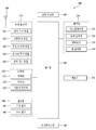
First, the overall configuration of an example of the mobile terminal described in the present application will be described below with reference to the related drawings. FIG. 1 is a block diagram for explaining a mobile terminal related to the present application, and a general configuration of a mobile terminal will be described with reference to FIG.
The mobile terminal 100 includes a wireless communication unit 110, an input unit 120, a sensing unit 140, an output unit 150, an interface unit 160, a memory 170, a control unit 180, ), And the like. The components shown in FIG. 1 are not essential for implementing the mobile terminal 100, so that the mobile terminal 100 described herein can have more or fewer components than the components listed above have. In addition, not all of the actual shapes and structures of the above-mentioned components are shown, and only the shapes and structures of some important components are shown in the figures following Fig. However, it is understandable to those skilled in the art that although not all illustrated, the described components may be included in the mobile terminal 100 to implement the functionality as the mobile terminal 100. [
The wireless communication unit 110 may be connected between the mobile terminal 100 and the wireless communication system or between the mobile terminal 100 and another mobile terminal 100 or between the mobile terminal 100 and the external server 100. [ Lt; RTI ID = 0.0 > wireless < / RTI > In addition, the wireless communication unit 110 may include one or more modules for connecting the mobile terminal 100 to one or more networks.
The wireless communication unit 110 may include at least one of a broadcast receiving module 111, a mobile communication module 112, a wireless Internet module 113, a short distance communication module 114, and a location information module 115 .
The input unit 120 includes a camera 121 or an image input unit for inputting a video signal, a microphone 122 for inputting an audio signal, an audio input unit, a user input unit 123 for receiving information from a user A touch key, a mechanical key, and the like). The voice data or image data collected by the input unit 120 may be analyzed and processed by a user's control command.
The sensing unit 140 may include at least one sensor for sensing at least one of information in the mobile terminal, surrounding environment information surrounding the mobile terminal, and user information. For example, the sensing unit 140 may include a proximity sensor 141, an illumination sensor 142, a touch sensor, an acceleration sensor, a magnetic sensor, A G-sensor, a gyroscope sensor, a motion sensor, an RGB sensor, an infrared sensor, a finger scan sensor, an ultrasonic sensor, A microphone 226, a battery gauge, an environmental sensor (for example, a barometer, a hygrometer, a thermometer, a radiation detection sensor, A thermal sensor, a gas sensor, etc.), a chemical sensor (e.g., an electronic nose, a healthcare sensor, a biometric sensor, etc.). The mobile terminal disclosed in this specification can combine and utilize the information sensed by at least two of the sensors.
The output unit 150 includes at least one of a display unit 151, an acoustic output unit 152, a haptic tip module 153, and a light output unit 154 to generate an output related to visual, auditory, can do. The display unit 151 may have a mutual layer structure with the touch sensor or may be integrally formed to realize a touch screen. The touch screen may function as a user input unit 123 that provides an input interface between the mobile terminal 100 and a user and may provide an output interface between the mobile terminal 100 and a user.
The interface unit 160 serves as a path to various types of external devices connected to the mobile terminal 100. The interface unit 160 is connected to a device having a wired / wireless headset port, an external charger port, a wired / wireless data port, a memory card port, And may include at least one of a port, an audio I / O port, a video I / O port, and an earphone port. The mobile terminal 100 may perform appropriate control related to the connected external device in correspondence with the external device being connected to the interface unit 160. [
In addition, the memory 170 stores data supporting various functions of the mobile terminal 100. The memory 170 may store a plurality of application programs or applications running on the mobile terminal 100, data for operation of the mobile terminal 100, and commands. At least some of these applications may be downloaded from an external server via wireless communication. Also, at least a part of these application programs may exist on the mobile terminal 100 from the time of shipment for the basic functions (e.g., telephone call receiving function, message receiving function, and calling function) of the mobile terminal 100. Meanwhile, the application program may be stored in the memory 170, installed on the mobile terminal 100, and may be operated by the control unit 180 to perform the operation (or function) of the mobile terminal.
In addition to the operations related to the application program, the control unit 180 typically controls the overall operation of the mobile terminal 100. The control unit 180 may process or process signals, data, information, and the like input or output through the above-mentioned components, or may drive an application program stored in the memory 170 to provide or process appropriate information or functions to the user.
In addition, the controller 180 may control at least some of the components illustrated in FIG. 1 in order to drive an application program stored in the memory 170. FIG. In addition, the controller 180 may operate at least two of the components included in the mobile terminal 100 in combination with each other for driving the application program.
The power supply unit 190 receives external power and internal power under the control of the controller 180 and supplies power to the components included in the mobile terminal 100. The power supply unit 190 includes a battery, which may be an internal battery or a replaceable battery.
At least some of the components may operate in cooperation with one another to implement a method of operation, control, or control of a mobile terminal according to various embodiments described below. In addition, the operation, control, or control method of the mobile terminal may be implemented on the mobile terminal by driving at least one application program stored in the memory 170. [
In the remaining figures that follow, the mobile terminal 100 is shown having a body in the form of a bar. However, the examples described in the present application are not limited thereto, and may have various structures and shapes. For example, the mobile terminal 100 may have a wearable body such as a pair of glasses, a watch, a bracelet and a necklace. That is, the configuration and description of the specific type of the mobile terminal 100 can be generally applied not only to the specific type of the mobile terminal 100, but also to other types of mobile terminals.
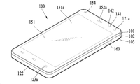
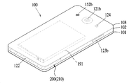
Following the general construction of the mobile terminal 100 described above, the structure of the mobile terminal 100 will be described in detail with reference to the related drawings. In this regard, FIGS. 2 and 3 are perspective views of an example of a mobile terminal viewed from different directions. 2 is a perspective view showing a front portion of the mobile terminal 100, and FIG. 3 is a perspective view showing a rear portion of the mobile terminal 100. As shown in FIG. 2 and 3 show the overall structure of the mobile terminal 100, all explanations are always referenced essentially to Figs. 2 and 3, except when particularly referenced figures are referred to.
As described above, the mobile terminal 100 has a body having a bar shape as a whole. The shape of the body can be varied as needed. Here, the body can be understood as a concept of referring to the mobile terminal 100 as at least one aggregate. Accordingly, all of the components described below can be described as being provided or installed in the body of the mobile terminal 100 or included in the body.
The mobile terminal 100 includes a case (for example, a frame, a housing, a cover, and the like) that forms an appearance. As shown, the mobile terminal 100 may include a front case 101 and a rear case 102. Various electronic components can be disposed in the inner space formed by the combination of the front case 101 and the rear case 102. [ These combined cases 101 and 102 may also form the contour of the mobile terminal 100 or the contour of its body. At least one middle case may be additionally disposed between the front case 101 and the rear case 102.
A display unit 151 is disposed on a front surface of the body of the mobile terminal 100 to output information. The display unit 151 is exposed from the front case 101 and can form a front surface of the mobile terminal 100 together with the front case 101. [
In some cases, electronic components may also be mounted on the rear case 102. Electronic parts that can be mounted on the rear case 102 include detachable batteries, an identification module, a memory card, and the like. In this case, a rear cover 103 for covering the mounted electronic components can be detachably coupled to the rear case 102. Therefore, when the rear cover 103 is detached from the rear case 102, the electronic parts mounted on the rear case 102 are exposed to the outside so as to be accessible.
As shown, when the rear cover 103 is coupled to the rear case 102, a side portion of the rear case 102 can be exposed. In some cases, the rear case 102 may be completely covered by the rear cover 103 during the engagement. Meanwhile, the rear cover 103 may be provided with an opening for exposing the camera 121b and the sound output unit 152b to the outside.
These cases 101, 102, and 103 may be formed by injection molding of synthetic resin or may be formed of metal such as stainless steel (STS), aluminum (Al), titanium (Ti), or the like.
The mobile terminal 100 may be configured such that one case provides the internal space, unlike the above example in which a plurality of cases provide an internal space for accommodating various electronic components. In this case, a universal mobile terminal 100 in which a synthetic resin or metal is connected from the side to the rear side can be realized.
Meanwhile, the mobile terminal 100 may include a waterproof portion (not shown) for preventing water from penetrating into the body of the mobile terminal 100. For example, the waterproof portion is provided between the window 151a and the front case 101, between the front case 101 and the rear case 102, or between the rear case 102 and the rear cover 103, And a waterproof member for sealing the inside space of the oven.
The mobile terminal 100 is provided with a display unit 151, first and second sound output units 152a and 152b, a proximity sensor 141, an illuminance sensor 142, a light output unit 154, Cameras 121a and 121b, first and second operation units 123a and 123b, a microphone 122, an interface unit 160, and the like.
2 and 3, a display unit 151, a first sound output unit 152a, a proximity sensor 141, a light intensity sensor 142, and a display unit 144 are disposed on the front surface of the body of the mobile terminal 100, A second operation unit 123b, a microphone 122, and an interface unit 160 are disposed on a side surface of the body, The second sound output unit 152b, and the second camera 121b are disposed on the rear surface of the body.
However, these configurations are not limited to this arrangement. These configurations may be excluded or replaced as needed, or placed on different planes. For example, the first operation unit 123a may not be provided on the front surface of the body of the mobile terminal 100, and the second sound output unit 152b may be provided on the side of the body rather than the rear surface of the body .
The display unit 151 displays (outputs) information processed by the mobile terminal 100. For example, the display unit 151 may display execution screen information of an application program driven by the mobile terminal 100 or UI (User Interface) and GUI (Graphic User Interface) information according to the execution screen information . Further, when the mobile terminal 100 is worn by the auxiliary device on the user's head, the display portion 151 can provide a stereoscopic image for the virtual reality to the user.
The display unit 151 may be a liquid crystal display (LCD), a thin film transistor-liquid crystal display (TFT LCD), an organic light-emitting diode (OLED), a flexible display display, a 3D display, and an e-ink display. The display unit 151 may include a display module (not shown) and a window 151a covering the display module. The display module may be a display element such as an LCD or an OLED as described above, and is a component that actually displays image information. The window 151a may be disposed at a portion exposed to the user of the display module, and may protect the display module from the outside. In addition to this protection function, the window 151a should allow the information displayed on the display module to be seen by the user. Accordingly, the window 151a can be made of a material having appropriate strength and transparency. Further, the display module may be directly attached to the rear surface of the window 151a. The display module can be attached directly to the window 151 in various ways, and the adhesive can be most conveniently used for direct attachment.
In addition, the display unit 151 may exist in two or more depending on the embodiment of the mobile terminal 100. In this case, the mobile terminal 100 may be provided with a plurality of display portions spaced apart from each other or disposed integrally with one another, or may be disposed on different surfaces, respectively.
The display unit 151 may include a touch sensor (not shown) that senses a touch to the display unit 151 so that a control command can be received by a touch method. The touch sensor may use at least one of various touch methods such as a resistance film type, a capacitive type, an infrared type, an ultrasonic type, and a magnetic field type. As an example, the touch sensor may be configured to convert a change in a pressure applied to a specific portion of a touch screen or a capacitance occurring at a specific portion into an electrical input signal, such as in a resistive film type and a capacitive type. The display unit 151 may constitute a touch screen as a kind of a touch input device in the mobile terminal together with the touch sensor. The display unit 151 can display predetermined image information while operating on a touch screen as a user interface. That is, the display unit 151 may function not only as the output unit 150 but also as the input unit 120. [ When a touch is made to the display unit 151, the touch sensor senses the touch, and the control unit 180 generates a control command corresponding to the touch based on the touch. The content input by the touch method may be a letter or a number, an instruction in various modes, a menu item which can be designated, and the like.
The touch sensor may be formed of a film having a touch pattern and disposed between the window 151a and the display module on the back surface of the window 151a or may be a metal wire directly patterned on the back surface of the window 151a. Alternatively, the touch sensor may be formed integrally with the display module. For example, the touch sensor may be disposed on the substrate of the display module or inside the display module.
In this way, the display unit 151 can form a touch screen together with the touch sensor. In this case, the touch screen can function as the user input unit 123 (see FIG. 1). If desired, a physical key (e.g., a push key) adjacent to the display unit 151, which is a touch screen, may additionally be provided as a user input 123 for convenient input of the user.
The first sound output unit 152a may be implemented as a receiver for transmitting a call sound to a user's ear and the second sound output unit 152b may be implemented as a loud speaker for outputting various alarm sounds or multimedia playback sounds. ). ≪ / RTI >
The window 151a of the display unit 151 may be provided with an acoustic hole for emitting the sound generated from the first acoustic output unit 152a. However, the present invention is not limited to this, and the sound may be configured to be emitted along an assembly gap (for example, a gap between the window 151a and the front case 101) between the structures. In this case, the appearance of the mobile terminal 100 can be made more simple because the hole formed independently for the apparent acoustic output is hidden or hidden.
The optical output unit 154 is configured to output light for notifying the occurrence of an event. Examples of the event include a message reception, a call signal reception, a missed call, an alarm, a schedule notification, an email reception, and reception of information through an application. The control unit 180 may control the light output unit 154 to terminate the light output when the event confirmation of the user is detected.
The first camera 121a processes an image frame of a still image or a moving image obtained by the image sensor in the photographing mode or the video communication mode. The processed image frame can be displayed on the display unit 151 and can be stored in the memory 170. [
The first and second operation units 123a and 123b may be collectively referred to as a manipulating portion as an example of a user input unit 123 operated to receive a command for controlling the operation of the mobile terminal 100 have. The first and second operation units 123a and 123b can be employed in any manner as long as the user is in a tactile manner such as touch, push, scroll, or the like. In addition, the first and second operation units 123a and 123b may be employed in a manner that the user operates the apparatus without touching the user through a proximity touch, a hovering touch, or the like.
In this figure, the first operation unit 123a is a touch key, but the present invention is not limited thereto. For example, the first operation unit 123a may be a mechanical key, or a combination of a touch key and a touch key.
The contents input by the first and second operation units 123a and 123b can be variously set. For example, the first operation unit 123a receives a command such as a menu, a home key, a cancellation, a search, and the like, and the second operation unit 123b receives a command from the first or second sound output unit 152a or 152b The size of the sound, and the change of the display unit 151 to the touch recognition mode.
The operation units 123a and 123b may be a touch input device having a structure similar to that of the touch screen applied to the display unit 151 described above. Unlike the touch screen, the operation units 123a and 123b are configured to input only a command without displaying image information, and the touch input device applied to such an operation unit can be called a touch pad.
Meanwhile, a rear input unit (not shown) may be provided on the rear surface of the body of the mobile terminal 100 as another example of the user input unit 123. The rear input unit is operated to receive a command for controlling the operation of the mobile terminal 100, and input contents may be variously set. For example, commands such as power on / off, start, end, scrolling, and the like, the size adjustment of the sound output from the first and second sound output units 152a and 152b, And the like can be inputted. The rear input unit may be implemented as a touch input, a push input, or a combination thereof.
The rear input unit may be disposed so as to overlap with the front display unit 151 in the thickness direction of the body of the terminal 100. For example, the rear input unit may be disposed at the rear upper end of the body of the terminal 100 so that the user can easily operate the detection unit when the user holds the body of the terminal 100 with one hand. However, the present invention is not limited thereto, and the position of the rear input unit may be changed.
When a rear input unit is provided on the rear surface of the body of the terminal 100, a new type of user interface using the rear input unit can be realized. In addition, the above-described touch screen or rear input unit replaces at least a part of the functions of the first operation unit 123a provided on the front surface of the body of the terminal 100 so that the first operation unit 123a is not disposed on the front surface of the body The display unit 151 can be configured as a larger screen.
Meanwhile, the mobile terminal 100 may be provided with a fingerprint recognition sensor for recognizing the fingerprint of the user, and the controller 180 may use the fingerprint information sensed through the fingerprint recognition sensor as authentication means. The fingerprint recognition sensor may be embedded in the display unit 151 or the user input unit 123.
The microphone 122 is configured to receive the user's voice, other sounds, and the like. The microphone 122 may be provided at a plurality of locations to receive stereophonic sound.
The interface unit 160 is a path through which the mobile terminal 100 can be connected to an external device. For example, the interface unit 160 may include a connection terminal (for example, a USB port) for connection with another device (for example, an earphone or an external speaker), a port for short-range communication An IrDA Port, a Bluetooth Port, a Wireless LAN Port, etc.), or a power supply terminal for supplying power to the mobile terminal 100. The interface unit 160 may be implemented as a socket for receiving an external card such as a SIM (Subscriber Identification Module) or a UIM (User Identity Module) or a memory card for storing information.
And a second camera 121b may be disposed on a rear surface of the body of the mobile terminal 100. [ In this case, the second camera 121b has a photographing direction which is substantially opposite to that of the first camera 121a.
The second camera 121b may include a plurality of lenses arranged along at least one line. The plurality of lenses may be arranged in a matrix form. Such a camera may be referred to as an array camera. When the second camera 121b is configured as an array camera, images can be taken in various ways using a plurality of lenses, and a better quality image can be obtained. The first camera 121a may also be constituted by such an array camera.
The flash 124 may be disposed adjacent to the second camera 121b. The flash 124 shines light toward the subject when the subject is photographed by the second camera 121b. In addition, the mobile terminal 100 may include a distance sensor disposed adjacent to the second camera 121b. The distance sensor may measure the distance between the predetermined object and the mobile terminal 100, similar to the proximity sensor 141 disposed in front of the mobile terminal 100. The measured distance may be used by the second camera 121b to obtain an appropriate image for the object, and may also be utilized for various other purposes.
A second sound output unit 152b may be additionally disposed on the body of the mobile terminal 100. [ The second sound output unit 152b may implement a stereo function together with the first sound output unit 152a and may be used for implementing a speakerphone mode in a call.
The body of the mobile terminal 100 is provided with a power supply unit 190 (see FIG. 1) for supplying power to the mobile terminal 100. The power supply unit 190 may include a battery 191 built in the body or detachable from the outside of the body.
The battery 191 may be configured to receive power through a power cable connected to the interface unit 160. In addition, the battery 191 may be configured to be wirelessly chargeable through a wireless charger. The wireless charging may be implemented by a magnetic induction method or a resonance method (magnetic resonance method).
In the figure, the rear cover 103 is coupled to the rear case 102 so as to cover the battery 191, thereby limiting the detachment of the battery 191 and protecting the battery 191 from external impact and foreign matter have. When the battery 191 is detachably attached to the body, the rear cover 103 may be detachably coupled to the rear case 102.
Although not shown in FIGS. 2 and 3, the substrate may be installed in the cases 101 and 102, and various electronic components, especially various processors that make up the control unit 180, may be mounted with other circuits and elements that assist them Lt; / RTI > Each of the components 110-190 shown in FIG. 1 may be directly mounted on the substrate so as to be controlled by the control unit 180, or may be installed in the case 101 or 102 and electrically connected to the substrate do. For example, although exposed to the outside, the window 151 (i.e., the touch sensor) and the display module may each be connected to the substrate through wiring. Accordingly, the controller 180 may be referred to as various names such as a controller and a controlling device, and may control all the components of the mobile terminal 100. Such a controlled component includes not only the components included in FIG. 1 but also other components to be described below.
The mobile terminal 100 may be provided with an accessory that protects the appearance or supports or expands the function of the mobile terminal 100. [ One example of such an accessory is a cover or pouch that covers or accommodates at least one side of the mobile terminal 100. [ The cover or pouch may be configured to interlock with the display unit 151 to expand the function of the mobile terminal 100. Another example of an accessory is a touch pen for supplementing or extending a touch input to the touch screen.
Meanwhile, at least one antenna 200 (see FIG. 1) for wireless communication may be provided in the body of the mobile terminal 100. The antenna 200 is an energy conversion device and can be configured to radiate or receive electromagnetic waves, i.e., radio waves. More specifically, an electrical signal is carried by charge and voltage, so it can move along a conductor but not along a non-conductor. On the other hand, electromagnetic waves can move along an insulator such as air. Thus, the electrical signal can be converted to electromagnetic waves and travel to a remote location through the space. According to this principle, the antenna 200 converts an electric signal into a radio wave and transmits the radio wave through the outside, that is, through a space, and also receives the radio wave through the space to convert it into an electric signal. Accordingly, the antenna 200 can transmit or receive an electrical signal so that the mobile terminal 100 can communicate with an external device or a network. The antenna 200 may form part of the wireless communication unit 110 (see FIG. 1), and may be embedded in the body of the mobile terminal 100 or formed in the cases 101 and 102. For example, the antenna 200 may be configured to be pulled out from the body of the mobile terminal 100. Alternatively, the antenna 200 may be formed in a film type and attached to the inner surface of the rear cover 103.
Recently, cases 101 and 102 made of metal are applied to the mobile terminal 100. [ The mobile terminal 100 can have a better appearance and can have a higher strength by the metallic cases 101 and 102. [ These metal cases 101 and 102 have sufficient conductivity and are exposed to the air to facilitate transmission and reception of radio waves. Considering both this arrangement and the material, the metal case 101, 102 may be suitable for constituting the antenna of the mobile terminal 100. [ Therefore, when the metal cases 101 and 102 are applied, the antenna 200 of the mobile terminal 100 can be configured using these cases 101 and 102. [ However, the antenna 200 by the metal case 101, 102 can easily touch the user's body, especially the user's hand, and the performance thereof may be greatly deteriorated by the so-called hand effect. The impedance of the antenna 200 is changed when the antenna 200 is in contact with the transmission line 200 and the impedance of the antenna 200 is changed from the impedance of the transmission line 200. [ ) ≪ / RTI > Due to such mismatch, the radiation efficiency of the antenna 200 may be lowered, and the transmission / reception ratio of signals or data may be significantly reduced. Therefore, when the mobile terminal 100 has the antenna 200 using the metal cases 101 and 102, deterioration in performance due to contact with the body needs to be minimized. For this reason, in the present application, the antenna 200 is designed to maintain at least intended performance even under various operating conditions, including contact with the body, and will be described in detail below with reference to the related drawings.
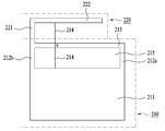
The antenna 200 of the present application can be implemented in various different examples, and a first example of the antenna 200 will be described first. 4 and 5 are a plan view and a side view showing a first example of the antenna according to the present application, and Fig. 6 is a circuit diagram showing an antenna according to the first example. More specifically, Fig. 5 is a side view of the antenna of Fig. 4 viewed from the direction "A ". 2 and 3 illustrate the overall structure of the terminal 100, and thus will be referred to in the following description together with the drawings for convenience of explanation.
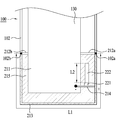
The antenna 200 may include a first antenna 210 disposed in the case 101 and a second antenna 220 disposed in the case 101. [ As described above, when the case 101 or 102 is made of a metal material, it can have a material and a position favorable to the radiation and reception of radio waves. Thus, the first antenna 210 may be constructed using metal cases 101, 102, precisely at least a portion thereof, and thus may be disposed in the case 101, 102 itself. The first antenna 210 corresponds to a part of the cases 101 and 102 forming the outer shape of the mobile terminal 100 and can be exposed to the outside of the mobile terminal 100 like the case 101 and 102. [ Meanwhile, the second antenna 220 may be formed separately from the cases 101 and 102 and disposed inside the cases 101 and 102. Since the second antenna 220 is covered by the case 101 or 102 or the cover 103, the second antenna 220 may not be exposed from the mobile terminal 100. With the arrangement of the first and second antennas 220, at least the second antenna 220 can be protected from contact with the body by the case and the covers 101, 102, and 103. Therefore, degradation of performance of the second antenna 220 during use of the mobile terminal can be prevented. 4-6 show conceptual structures and circuitry, the arrangement described above may not be explicitly shown in these figures, but can be clearly identified from the description of Figs. 9 and 11 and their associated descriptions.
In addition, the antenna 200 may basically include a feed 214 that supplies power or voltage to the circuit of the antenna 200 in common. If feeds are provided to the first and second antennas 210 and 220, respectively, the circuitry of the antenna 200 may be complicated and a change to the circuit design of the mobile terminal 100 itself may be required. For this reason, the second antenna 220 may be directly coupled to the first antenna 210. This direct coupling can be better understood from the circuit diagram of FIG. More specifically, the first and second antennas 210 and 220 may share many structures by their direct coupling. 6, the first antenna 210 requires a feed 214 (see FIG. 6 (a)) and this feed is also indispensable for operation of the second antenna 220 (see FIG. 6 b)). Thus, as mentioned above, if the first and second antennas 210 and 220 are directly coupled to each other, they can share the feed 214 with each other (see Fig. 6 (c)). Further, as shown in Figs. 6 (a) and 6 (b), the antenna 200 may commonly require a ground 211 for protecting its circuit. Therefore, for the same reason, if the first and second antennas 210 and 220 are directly coupled to each other, they can also share the ground 211 (see Fig. 6 (c)). By this direct coupling, the first and second antennas 210 and 220 can be structurally and electrically coupled to each other. That is, the first and second antennas 210 and 220 are distinguished from each other only in terms of their function, and are actually formed as a single antenna 200. Accordingly, the antenna 200 can have a simple structure while providing various designed functions or performances, and the production cost is not increased. Further, due to the simple structure of this antenna 200, the mobile terminal 100 can be made compact while ensuring the intended function.
Following the basic configuration, i.e., the basic functionality and structure of the antenna 200 described above, the detailed configuration of the antenna 200 will be described in detail below. In the antenna 200, the first and second antennas 210 and 200 may be made up of various types of antennas. Of these types of antennas, a slot antenna and an IF antenna (Inverted-F antenna) Structure and high radiation efficiency, it can be suitable for the antenna of the mobile terminal 100. [ The slot antenna basically requires a slot structure for radio wave radiation. As shown in Figs. 2 and 3, the cases 101 and 102 are generally made up of rectangular frames, which can be advantageous for forming slots. On the other hand, the IF antenna requires a predetermined length of arm structure for radio wave radiation, and such an arm structure can be easily disposed in the narrow internal space of the mobile terminal 100. [ For this reason, as shown in FIGS. 4 to 6, in the first example of the antenna 200, the first antenna 210 using the cases 101 and 102 may be a slot antenna, 2 antenna 220 may be an IF antenna. Therefore, in the following, the structure of the antenna 200 according to the first example will be described with reference to Figs. 4-6.
First, the first antenna 210 is formed of a slot antenna, and may be made entirely of a conductive material for movement of an electric signal formed by a current and a voltage. The first antenna 210 may include a ground 211 for grounding it to protect the antenna circuit. The first antenna 210 may also include a pair of shorting legs 212a, 212b extending from the ground 211. [ The pair of legs 212a, 212b may be spaced apart from one another to form a slot 215. The legs 212a and 212b short-circuit the antenna circuit to generate a voltage and current difference for proper radiation in the antenna 200. [ The first antenna 210 may also include an arm 213 extending between the legs 212a, 212b. The arm 213 is connected to the legs 212a and 212b respectively and thus can radiate radio waves by forming the slots 215 together with the legs 212a and 212b and the ground 211. [ The first antenna 210 may include a feed 214 configured to supply power (i.e., voltage) to the circuitry of the first antenna 210. The feed 214 may extend across the slot 215 and may be connected to the ground 211 and the arm 213, respectively, so that radio waves may be emitted from the slot 215.
The second antenna 220 is formed of an IFA antenna and may be made entirely of a conductive material for movement of electrical signals formed by current and voltage, like the first antenna 210. As described above, the second antenna 220 may be directly coupled to or coupled to the first antenna 220. [ More specifically, as shown, the second antenna 220 may be directly coupled to the feed 214 of the first antenna 210. [ Thus, as shown, the second antenna 220 may share the feed 214 primarily with the first antenna 210. [ The second antenna 220 may also share the first antenna 210 and the ground 211 since the second antenna 220 may be connected to the ground 211 through the feed 214. [ On the other hand. The second antenna 220 may be disposed in a plane different from a plane on which the first antenna 210 is disposed (hereinafter referred to as a first plane) (hereinafter referred to as a second plane). 4 and 5, the second antenna 220 is spaced apart from the first plane by a predetermined distance and includes a first antenna 210, i.e., a first antenna 210 disposed above the first plane 210, 2 plane. However, although not shown, the second antenna 220 may be disposed in a second plane located below the first plane. That is, the second antenna 220 may be stacked on or overlapped with the first antenna 210 while maintaining a predetermined gap with the first antenna 210. Accordingly, the first and second antennas 210 and 220 coupled to each other by this arrangement, that is, the antenna 200 according to the first example, can be compactly formed, and can be applied to the mobile terminal 100 having a small size Can be suitable.
4 to 6, the second antenna 220 may include legs 221 protruding from a first plane in which the first antenna 210 is disposed. The legs 221 short circuit the antenna and generate a voltage and current difference in the second antenna 220 for radiating radio waves. More specifically, the legs 221 are connected directly to the feed 214 and may extend to project from the feed 214. Thus, the second antenna 220 may also be powered from the feed 214 along with the first antenna 210, thereby sharing the feed 214 with the first antenna 210. In addition, the second antenna 220 may include an arm 222 extending from the leg 221. The arm 222 serves to actually radiate radio waves at the second antenna 220. More specifically, the arm 222 may extend generally parallel thereto while being spaced from the first antenna 210. Thus, the second antenna 220 may be disposed within a second plane that is generally parallel to the first plane of the first antenna 210.
Meanwhile, the first and second antennas 210 and 220 must have a predetermined length in order to radiate radio waves of an intended frequency. For example, in a slot antenna that is the first antenna 210, the length L1 of the slot 215 or the arm 213 should be set to lambda / 2, where lambda corresponds to the wavelength of the radio wave. In the IF antenna, which is the second antenna 220, the length L2 of the arm 222 should be set to? / 4. That is, the adjustment of the lengths L1 and L2 of the slot / arm 213 and the arm 222 may result in the adjustment of the frequency of the radio waves that the first and second antennas 210 and 220 receive, have. Here, the resonant frequency can be defined as a frequency at which the antenna exhibits the maximum performance. Thus, by adjusting the lengths L1 and L2, the first and second antennas 210 and 220 can be tuned to have the intended performance. For example, in the design for tuning, the length L2 may be changed relative to the length L1 when the length L1 has a fixed value. Also, when the length L2 has a fixed value, the length L1 may be relatively changed with respect to the length L2.
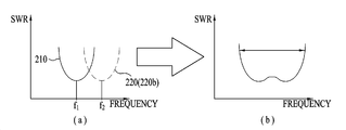
The tuning of such an antenna is described in more detail below with reference to the associated drawings. FIG. 12 is a graph of SWR (Standing Wave Ratio) versus frequency showing a wide band applied to the antenna of the present application, and FIG. 13 is a graph of SWR versus frequency showing multi-band applied to the antenna of the present application. Here, SWR can be defined as the ratio of the maximum value of the power (or voltage) received or radiated by the antenna to its minimum value. Therefore, a small value of SWR means that the impedance of the antenna matches the impedance of the feeder line, and thus the antenna is performing well. Therefore, at the resonance frequency of the antenna, SWR can represent the minimum value. Also, since the antenna can exhibit a somewhat good performance in a certain frequency range near the resonance frequency, this range can also be a reference for the antenna performance together with the resonance frequency. Such a frequency range is defined as a resonance frequency band, and is indicated by a solid line or a dotted line in Figs. 12 and 13.
The tuning of the antenna 200 first adjusts the length L1 and L2 so that the resonance frequency f2 of the second antenna 220 is equal to the resonance frequency f1 of the first antenna 210 ). Thus, even if the first antenna 210 is operated with low performance due to contact with the body, the second antenna 220 can be operated with the intended performance on behalf of the first antenna 210.
12 (a), by adjusting the lengths L1 and L2, the second antenna 220 can adjust the resonance frequency f1 adjacent to the resonance frequency f1 of the first antenna 210 f2). These resonance frequencies f1 and f2 are different but do not have a large difference. Therefore, as shown in FIG. 12 (b), the resonance frequency bands of the first and second antennas 210 and 220 are superimposed on each other, and the band width exhibiting good performance is substantially extended . That is, the second antenna 220 has a resonance frequency f2 set adjacent to the resonance frequency f1 of the first antenna 210 so that its resonance frequency band overlaps the resonance frequency band of the first antenna 210, Lt; / RTI > For this reason, the antenna 220 may have one wide band, a wide band, and the performance may be enhanced. 13, the resonance frequency f2 of the second antenna 220 is controlled to be larger than the resonance frequency f1 of the first antenna 210 by the adjustment of the lengths L1 and L2, . ≪ / RTI > Therefore, unlike the example of FIG. 12, the resonance frequency bands of the first and second antennas 210 and 220 do not overlap with each other and can exist independently of each other. That is, the second antenna 220 has a resonance frequency (f1) having a large difference with respect to the resonance frequency f1 of the first antenna 210 so that the resonance frequency band of the second antenna 220 does not overlap the resonance frequency band of the first antenna 210 f2). For this reason, the antenna 220 may have practically multi-band, i.e., multi-band characteristics, and may be adaptive to signals of various bands. Therefore, even if the performance of the first antenna 210 deteriorates due to physical contact, the performance deterioration of the first antenna 210 is compensated for by the multiband or wide band characteristics due to the frequency tuning of the second antenna 220 . For this reason, performance can be maintained throughout the antenna 200 regardless of the performance degradation of the first antenna 210 due to physical contact and other operating environments. Furthermore, the antenna 200 can have the wide or multi-band characteristics described above, thereby providing the mobile terminal 100 with improved performance under normal operating conditions without physical contact and other degradation conditions.
The first example of the antenna 200 described above can be modified into various structures. Fig. 7 is a plan view showing a modified example of the first example of the antenna, and Fig. 8 is a plan view showing a further modified example of the first example of the antenna. The basic structure of the first example described above, that is, the function and structure, can be similarly applied to the modifications of Figs. 7 and 8, and a further explanation thereof will be omitted. Also, in the detailed configuration, the elements of the modification may have the same functions as the corresponding elements described above. That is, the functions of the ground, leg, arm, and feed of the first and second antennas described with reference to FIGS. 4 and 5 can be directly applied to the corresponding components of the modifications of FIGS. Therefore, only the structure of the modifications will be described in detail below. 7 and 8, the tuning of the antenna 200 can also be directly applied to the variants without any particular modification, since these variants also have the basic configuration of the basic example of Figs. 4 and 5, i.e. the first example . Thus, the tuning of the variant is not further described below.
First, as shown in FIG. 7, unlike the basic examples of FIGS. 4 and 5, the first and second antennas 210 and 220 may be disposed in substantially the same plane. More specifically, the second antenna 220 may be disposed outside the first antenna 210 while being disposed in the same plane as the first antenna 210. The legs 221 of the second antenna 220 are spaced apart from any one of the legs 212a and 212b of the first antenna 210 toward the outside of the first antenna 210 by a predetermined length Can be extended. The arm 222 of the second antenna 220 may extend substantially parallel to the arm 213 of the first antenna 210 in the same plane as the first antenna 210 from the leg 221 have. The feed 214 may extend beyond the arm 213 of the first antenna to the arm 222 of the second antenna 220 to supply power to the second antenna 220, 2 antennas 210 and 220 may share the feed 214 and ground 211. 7, the arm 213, the leg 212 and the slot 215 of the first antenna 210 are disposed between the ground 211 and the second antenna 220 . Since the arm 213 and the slot 215 correspond to a substantial component that radiates radio waves in the first antenna 210, the first antenna 210 itself is disposed between the second antenna 220 and the ground 211 As shown in FIG.
Also, as shown in FIG. 8, the first and second antennas 210 and 220 may be disposed substantially in the same plane as in the modification of FIG. The second antenna 220 may be disposed in the same plane as the first antenna 210 and may be disposed inside the first antenna 210. For this arrangement, the first antenna 210 may be spaced from the ground 211 by a predetermined distance while being disposed in the same plane as the ground 211. That is, the legs 212a and 212b, the arms 213a and 213b, and the slots 215, which are substantial components of the first antenna 210, may be spaced apart from the ground 211 by a predetermined distance. More specifically, the pair of arms 213a and 213b may be spaced apart from each other by a predetermined distance, and may extend substantially parallel to each other in the same plane as the ground 211. [ These arms 213a and 213b may be spaced apart from the ground 211 by a predetermined distance. Further, the pair of legs 212a and 212b may be disposed at both ends of the arms 213a and 213b, respectively. Thus, the slots 215 closed by the arms 213a, 213b and the legs 212a, 212b can be formed at a position spaced apart from the ground 211. [ Any one of the legs 212a and 212b may be connected to the ground 211 for grounding. The legs 221 of the second antenna 220 are connected to the ground 211 from the other one of the legs 212a and 212b of the first antenna 210 that is not connected to the ground 211, To a predetermined length. The arm 222 of the second antenna 220 may extend substantially parallel to the arm 213 of the first antenna 210 in the same plane as the first antenna 210 from the leg 221 have. The feed 214 may extend beyond the arm 213b of the first antenna to the arm 222 of the second antenna 220 to supply power to the second antenna 220, 2 antennas 210 and 220 may share the feed 214 and ground 211. 8, the arm 222 and the leg 221 of the second antenna 220 are connected to the ground 211, the slot 215 of the first antenna 210, the arm 213a , 213b, and legs 212a, 212b. The arms 222 and legs 221 are the substantial components of the second antenna 220 and the slots 215 and the arms 213a and 213b and the legs 212a and 212b are substantially It can be explained that the second antenna 220 itself is disposed between the first antenna 220 and the ground 211. [ In addition, since the slot 215, the arms 213a and 213b, and the legs 212a and 212b can form the first antenna 210 together with the ground 211, the second antenna 220 can be connected to the first antenna 210 210 or placed within the first antenna 210. [0040]
When the antenna 200 according to the first example and the modifications thereof are actually applied to the mobile terminal 100, they can also be used as an antenna in accordance with the design and structure of the mobile terminal 100, while maintaining the above- 8 can have a practical structure different from the conceptual structure shown in FIG. Therefore, in the following, a practical example of the antenna 200 will be described in detail with reference to the related drawings. 9 is a plan view showing an actual example of an antenna according to a first example applied to a mobile terminal. 10 is a plan view showing a further modified example of the antenna according to the first example, and Fig. 11 is a plan view showing an actual example of the antenna of Fig. 10 applied to the mobile terminal. The actual example described below relates to the antenna 200 according to the first example shown in Figs. 4 and 5, i.e. the basic example. However, it will be apparent to those skilled in the art that the modifications of Figs. 7 and 8 can also be practically implemented from the actual examples without any particular modification.
First, Fig. 9 shows a rear portion from which the cover 103 is removed from the mobile terminal 100 of Fig. With the removal of the cover 103, the rear portion of the case 102 is exposed, and the substrate 130 can also be exposed together. First, in the first antenna 210, the ground 211 may be a part of the substrate 130. Actually, the mobile terminal 130 also includes a ground on the substrate 130 for protecting the circuit, and the antenna 200 may share the ground of the mobile terminal 100 as well. As described above, the arm 213 is a component that actually receives or radiates radio waves from the first antenna 210. [ In this regard, the case 102 is made of a metal material suitable for radio wave radiation, and is exposed to the outside of the mobile terminal 100. Thus, the arm 213 in the first antenna 210 can be implemented using the case 102. [ More specifically, a pair of legs 212a and 212b can extend from the substrate 130, which is the ground 211, to the case 102. [ As indicated by oblique lines by the arrangement of these legs 212a and 212b, the distance from the point 102a to which the one leg 212a is connected to the case 102 to the other leg 212b, A part of the case 102 between the upper case 102b and the lower case 102b can function as the arm 213. It should also be noted that legs 212a and 212b as well as portions of the case 102, i.e., the arm 213 and a portion of the substrate 130 facing the portion of the case 102, The slot 215 can be formed. Further, across the formed slot 215, the feed 214 couples the ground 211, which is part of the substrate 130, to the arm 213, which is part of the case 102, Can supply. These feeds 214 may be connected to a power terminal formed on the substrate 130 and may share power with the mobile terminal 100. By changing the connection points 102a and 102b, the length L1 of the arm 213 and the slot 215 (see FIG. 4) can be changed, so that the resonance frequency of the first antenna 210 can be changed have. Accordingly, by adjusting the positions of the connection points 102a and 102b, that is, the legs 212a and 212b, the first antenna 210 can be tuned to achieve desired performance.
The leg 221 of the second antenna 220 is connected to the feed 214 and may protrude from the first plane in which the first antenna 210 is disposed, The arm 222 of the second antenna 220 may also extend substantially parallel to the first plane, that is, the exposed rear surface of the substrate 130 or the case 102. Therefore, the second antenna 220 can be disposed on the space between the substrate 130 and the case 102, and can effectively utilize the inner space of the unused mobile terminal 100. The second antenna 220 has its length L2 (Fig. 4 (b)) so that the second antenna 220, and further, the antenna 200 can achieve the intended performance as a whole, Can be tuned. More specifically, if the first antenna 210 has a fixed fixed frequency f1 according to a predetermined length L1, the second antenna 220 can adjust the length L2, The second antenna 210 may have a resonant frequency f2 that is equal to the resonant frequency f1 of the first antenna 210 that has the intended performance on behalf of the first antenna 210, Can be operated. On the other hand, as shown in FIG. 12 (a), by adjusting the length L2, the second antenna 220 can have a resonance frequency f2 adjacent to the resonance frequency f1, As shown in FIG. 12 (b), the antenna 200 may have wide band characteristics as a whole. 13, the resonance frequency f2 of the second antenna 220 may be significantly different from the resonance frequency f1 of the first antenna 210 by adjusting the length L2 of the first antenna 210. In other words, And the antenna 220 may have practically multi-band characteristics. More specifically, in this multi-band, any one of the antennas 210 and 220 may have a low band, that is, a resonance frequency band of a low band, and the other may have a low band, Band resonance frequency band. 4 and 5, the rectangular cross-sectional shape of the case 102 is advantageous for forming the slot, so that the first antenna 210 formed in the case 102 exposed to the outside is inserted into the slot 102, Antenna. Further, the lengths L1 and L2 of the antenna 200 are proportional to the wavelength?, While this wavelength? Is inversely proportional to the frequency. Thus, a high resonant frequency requires relatively short lengths (L1, L2) while a low resonant frequency may require relatively long lengths (L1, L2). 9, the length L1 of the first antenna 210, i.e., the slot 215 and the length of the arm 213, can be easily extended by moving the legs 212a, 2112b. On the other hand, if the second antenna 220 is elongated, it may interfere with other components, such as switches, buttons, sensors, disposed between the case 102 and the substrate 130. Therefore, the first antenna 210 is advantageous in the resonance frequency band of the low band. In addition, since the length L1 is? / 2 and the length L2 is? / 4, the length L2 can be shorter than the length L1 with the same resonance frequency, At frequencies, it can be shorter. Therefore, it is advantageous for the second antenna 220 having a resonance frequency band of a high band to be disposed in a limited space. Accordingly, in the multiband characteristic, the first antenna 210 may have a resonance frequency band of a low band, and the second antenna 220 may have a resonance frequency band of a high band. Due to the multi-band and wide-band characteristics, the antenna 200 can maintain the intended performance as a whole even if the performance of the first antenna 210 is degraded, and may provide a better performance.
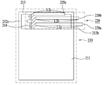
The second antenna 220 may be tuned to have only one of the characteristics described above, but may be further designed to have a plurality of the characteristics described above. The characteristics may be determined according to the resonance frequency of the second antenna 220 and a band formed around the resonance frequency. Accordingly, the second antenna 220 may include auxiliary antennas 220a, 220b, and 220c having a plurality of different resonance frequencies and bands thereof to have a plurality of characteristics. These auxiliary antennas 220a, 220b, and 220c are described in more detail below with reference to FIGS. 10 and 11. FIG. FIG. 10 shows a conceptual structure of a modification of the antenna 200 having the auxiliary antennas 220a, 220b and 220c, and FIG. 11 shows an example in which such a modification is applied to the mobile terminal 100 in practice.
In this modification, the first antenna 210 has already been described above with reference to FIGS. 4, 5, and 9, and a further explanation thereof will be omitted. 10 and 11, the second antenna 220 firstly includes a first antenna 210 having a resonance frequency f2a equal to the resonance frequency f1 of the first antenna 210 and a band corresponding thereto, 220a. As described above, the first antenna 210 may be designed to have a resonance frequency band of a low band. Since the low resonance frequency requires a relatively long antenna length, in order to obtain the resonance frequency f2a equal to the resonance frequency f1, the length L2a of the first auxiliary antenna 220a, as shown, May be relatively longer than the lengths L2b, L2c of the first and second lines. In addition, the second antenna 220 may include a second auxiliary antenna 220b having a resonance frequency f2b adjacent to the resonance frequency f1 for a wide band. The resonance frequency f2b of the second auxiliary antenna 220 is also close to the resonance frequency f1a of the first auxiliary antenna 220a which is equal to the resonance frequency f1 of the first antenna 210. [ Therefore, the length L2b of the second auxiliary antenna 220b may be set to be close to the length L2a of the first auxiliary antenna 220a. 10 and 11, the length L2b is slightly shorter than the length L2a, but may be slightly longer than the length L2a. Furthermore, the second antenna 220 may include a third auxiliary antenna 220c having a resonance frequency f2c set to have a large difference from the resonance frequency f1 of the first antenna 210 for multi-band. have. Since the first antenna 210 is designed to have a resonance frequency band of a low band, the third auxiliary antenna 220c may be designed to have a resonance frequency band of a high band in order to realize multi-band. Therefore, the length L2c of the third auxiliary antenna 220c may be significantly shorter than the lengths L2a and L2b of the other auxiliary antennas as shown in the figure.
For a more realistic design, the mobile terminal 100 may typically use the frequency band 700-2600 MHz for communication. Therefore, when the above-described modification is applied to the mobile terminal 100, for example, the first antenna 100 can be designed to have a resonance frequency f1 that is 700 MHz of the low band. The first auxiliary antenna 220a may have a resonance frequency f2a of 700 MHz which is the same as the resonance frequency f1. Also, the second auxiliary antenna 220b may have a resonance frequency f2b slightly larger than the resonance frequency f1, but 800 MHz adjacent thereto, in order to realize a wide band. Furthermore, the third auxiliary antenna 230c may have a high-band resonance frequency band for multi-band, and may be designed to have a resonance frequency band of 1700-2600 MHz, for example.
The antenna 200 may include all of the auxiliary antennas 220a, 220b, and 220c, and may optionally include one or two of these auxiliary antennas depending on the desired characteristics. As shown in FIG. 11, these auxiliary antennas 220a, 220b, and 220c are all connected to the feed 214 and may be arranged in parallel with each other within the space between the substrate 130 and the case 102. Therefore, by applying the auxiliary antennas 220a, 220b, and 220c, the antenna 200 can utilize the space in the mobile terminal 100 to the maximum while securing various characteristics. Also, even when the performance of the first antenna 210 is degraded due to the auxiliary antennas 220a, 220b, and 220c, the antenna 200 can continuously maintain a desired performance. Further, due to the various characteristics imparted by the auxiliary antennas 220a, 220b, and 220c, the antenna 200 can provide a compact size and improved performance.
The antenna 200 may be designed to have other structures while performing the same function in addition to the first example and the modifications described above. Other examples of such an antenna 200 are described below with reference to the associated drawings. 14 is a plan view showing a second example of the antenna according to the present application. Fig. 15 is a plan view showing a third example of the antenna according to the present application, and Fig. 16 is a plan view showing a fourth example of the antenna according to the present application. The basic configuration such as the basic function, arrangement, material, etc. of the first and second antennas described in the first example can be similarly applied to the examples 2-4 to be described. Also in the detailed configuration, the functions of the ground, leg, arm, and feed of the first and second antennas according to the first example may be the same as those of the corresponding elements of the examples 2-4 to be described. Therefore, in the following, a further explanation of the basic configuration and functions of the components is omitted, and the detailed structure of the second to fourth examples is explained in more detail.
14, the first antenna 210 exposed in the antenna 200 according to the second example may be an IF antenna, and the second antenna 220 not exposed may be a slot antenna. have.
The second antenna 220 may include a pair of legs 222a and 222b extending from the ground 211. [ The pair of legs 222a, 222b may be spaced apart from one another to form a slot 225. In addition, the second antenna 220 may include an arm 223 extending between the legs 222a, 222b. The arms 223 are each connected to the legs 222a and 222b so that they can radiate radio waves by forming the slots 225 together with the legs 222a and 222b and the ground 211. [ Feed 214 extends across slot 225 and may be connected to ground 211 and arm 223, respectively.
The first antenna 210 may be disposed outside the second antenna 220. The legs 212 of the first antenna 210 may extend from either the legs 222a or 222b of the second antenna 220 or from the arm 223 toward the outside of the second antenna 220 And can be extended to a predetermined length. The arm 213 of the first antenna 210 may extend substantially parallel to the arm 223 of the second antenna 220 from the leg 212. The feed 214 may extend beyond the arm 223 of the second antenna to the arm 213 of the first antenna 210 to supply power to the first antenna 210, 2 antennas 210 and 220 may share the feed 214 and ground 211.
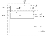
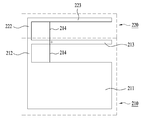
As shown in FIG. 15, in the antenna 200 according to the third example, the first and second antennas 210 and 220 may be both slot antennas.
The first antenna 210 may include a pair of legs 212a, 212b extending from the ground 211. [ The pair of legs 212a, 212b may be spaced apart from one another to form a slot 215. Also, the first antenna 210 may include an arm 213 extending between the legs 212a, 212b. The arm 213 is connected to the legs 212a and 212b respectively and thus can radiate radio waves by forming the slots 215 together with the legs 212a and 212b and the ground 211. [ Feed 214 extends across slot 215 and may be connected to ground 211 and arm 213, respectively. In the second antenna 220, the pair of legs 222a and 222b may extend from the arm 213 of the first antenna 210 while being spaced apart from each other by a predetermined distance. The arm 223 extends between the legs 222a and 222b and can be connected to the legs 222a and 222b, respectively. Thus, the legs 222a, 222b and the two arms 213, 223 can additionally form a slot 225 to radiate radio waves. The feed 214 may extend beyond the arm 213 of the first antenna to extend through the slot 225 to the arm 223 of the second antenna 220 to power the second antenna 220 as well. have. Accordingly, the first and second antennas 210 and 220 may share the feed 214 and the ground 211.
Finally, as shown in FIG. 16, in the antenna 200 according to the fourth example, both the first and second antennas 210 and 220 may be IF antennas.
The first antenna 210 may include legs 212 extending from the ground 211. In addition, the first antenna 210 may include an arm 213 extending from the leg 212. The arm 213 can be extended while maintaining a predetermined gap with respect to the ground 211. [ Feed 214 may be coupled to ground 211 and arm 213, respectively, to provide power. In the second antenna 220, the leg 222 may extend from the arm 213 of the first antenna 210. Also, the arm 223 may extend from the leg 222 while maintaining a predetermined spacing relative to the arm 213. The feed 214 may extend beyond the arm 213 of the first antenna to the arm 223 of the second antenna 220 to power the second antenna 220 as well. Accordingly, the first and second antennas 210 and 220 may share the feed 214 and the ground 211.
The lengths of the first and second antennas 210 and 220 can be adjusted in the second to fourth examples of FIGS. Thus, tuning of the antenna 200 described above can also be directly applied to these 2-4 examples without any particular modification. Also, based on the practical example described in Fig. 9, the second to fourth examples can be practically applied to the mobile terminal 100 directly without substantial modification and further consideration.
The foregoing detailed description should not be construed in all aspects as limiting and should be considered illustrative. The scope of the present invention should be determined by rational interpretation of the appended claims, and all changes within the scope of equivalents of the present invention are included in the scope of the present invention.