KR20170039728A - Fan, pump, motor assembly and integrated circuit for motor drive - Google Patents
Fan, pump, motor assembly and integrated circuit for motor drive Download PDFInfo
- Publication number
- KR20170039728A KR20170039728A KR1020177006216A KR20177006216A KR20170039728A KR 20170039728 A KR20170039728 A KR 20170039728A KR 1020177006216 A KR1020177006216 A KR 1020177006216A KR 20177006216 A KR20177006216 A KR 20177006216A KR 20170039728 A KR20170039728 A KR 20170039728A
- Authority
- KR
- South Korea
- Prior art keywords
- circuit
- rotor
- switch
- motor
- permanent magnet
- Prior art date
Links
Images


Classifications
-
- H—ELECTRICITY
- H02—GENERATION; CONVERSION OR DISTRIBUTION OF ELECTRIC POWER
- H02P—CONTROL OR REGULATION OF ELECTRIC MOTORS, ELECTRIC GENERATORS OR DYNAMO-ELECTRIC CONVERTERS; CONTROLLING TRANSFORMERS, REACTORS OR CHOKE COILS
- H02P6/00—Arrangements for controlling synchronous motors or other dynamo-electric motors using electronic commutation dependent on the rotor position; Electronic commutators therefor
- H02P6/08—Arrangements for controlling the speed or torque of a single motor
-
- H—ELECTRICITY
- H02—GENERATION; CONVERSION OR DISTRIBUTION OF ELECTRIC POWER
- H02P—CONTROL OR REGULATION OF ELECTRIC MOTORS, ELECTRIC GENERATORS OR DYNAMO-ELECTRIC CONVERTERS; CONTROLLING TRANSFORMERS, REACTORS OR CHOKE COILS
- H02P6/00—Arrangements for controlling synchronous motors or other dynamo-electric motors using electronic commutation dependent on the rotor position; Electronic commutators therefor
- H02P6/20—Arrangements for starting
-
- H—ELECTRICITY
- H01—ELECTRIC ELEMENTS
- H01L—SEMICONDUCTOR DEVICES NOT COVERED BY CLASS H10
- H01L23/00—Details of semiconductor or other solid state devices
- H01L23/48—Arrangements for conducting electric current to or from the solid state body in operation, e.g. leads, terminal arrangements ; Selection of materials therefor
- H01L23/488—Arrangements for conducting electric current to or from the solid state body in operation, e.g. leads, terminal arrangements ; Selection of materials therefor consisting of soldered or bonded constructions
- H01L23/49—Arrangements for conducting electric current to or from the solid state body in operation, e.g. leads, terminal arrangements ; Selection of materials therefor consisting of soldered or bonded constructions wire-like arrangements or pins or rods
-
- F—MECHANICAL ENGINEERING; LIGHTING; HEATING; WEAPONS; BLASTING
- F04—POSITIVE - DISPLACEMENT MACHINES FOR LIQUIDS; PUMPS FOR LIQUIDS OR ELASTIC FLUIDS
- F04D—NON-POSITIVE-DISPLACEMENT PUMPS
- F04D13/00—Pumping installations or systems
- F04D13/02—Units comprising pumps and their driving means
- F04D13/06—Units comprising pumps and their driving means the pump being electrically driven
-
- G—PHYSICS
- G01—MEASURING; TESTING
- G01B—MEASURING LENGTH, THICKNESS OR SIMILAR LINEAR DIMENSIONS; MEASURING ANGLES; MEASURING AREAS; MEASURING IRREGULARITIES OF SURFACES OR CONTOURS
- G01B7/00—Measuring arrangements characterised by the use of electric or magnetic techniques
- G01B7/003—Measuring arrangements characterised by the use of electric or magnetic techniques for measuring position, not involving coordinate determination
-
- G—PHYSICS
- G01—MEASURING; TESTING
- G01D—MEASURING NOT SPECIALLY ADAPTED FOR A SPECIFIC VARIABLE; ARRANGEMENTS FOR MEASURING TWO OR MORE VARIABLES NOT COVERED IN A SINGLE OTHER SUBCLASS; TARIFF METERING APPARATUS; MEASURING OR TESTING NOT OTHERWISE PROVIDED FOR
- G01D5/00—Mechanical means for transferring the output of a sensing member; Means for converting the output of a sensing member to another variable where the form or nature of the sensing member does not constrain the means for converting; Transducers not specially adapted for a specific variable
- G01D5/12—Mechanical means for transferring the output of a sensing member; Means for converting the output of a sensing member to another variable where the form or nature of the sensing member does not constrain the means for converting; Transducers not specially adapted for a specific variable using electric or magnetic means
- G01D5/14—Mechanical means for transferring the output of a sensing member; Means for converting the output of a sensing member to another variable where the form or nature of the sensing member does not constrain the means for converting; Transducers not specially adapted for a specific variable using electric or magnetic means influencing the magnitude of a current or voltage
- G01D5/142—Mechanical means for transferring the output of a sensing member; Means for converting the output of a sensing member to another variable where the form or nature of the sensing member does not constrain the means for converting; Transducers not specially adapted for a specific variable using electric or magnetic means influencing the magnitude of a current or voltage using Hall-effect devices
-
- G—PHYSICS
- G01—MEASURING; TESTING
- G01R—MEASURING ELECTRIC VARIABLES; MEASURING MAGNETIC VARIABLES
- G01R33/00—Arrangements or instruments for measuring magnetic variables
- G01R33/0011—Arrangements or instruments for measuring magnetic variables comprising means, e.g. flux concentrators, flux guides, for guiding or concentrating the magnetic flux, e.g. to the magnetic sensor
-
- G—PHYSICS
- G01—MEASURING; TESTING
- G01R—MEASURING ELECTRIC VARIABLES; MEASURING MAGNETIC VARIABLES
- G01R33/00—Arrangements or instruments for measuring magnetic variables
- G01R33/0023—Electronic aspects, e.g. circuits for stimulation, evaluation, control; Treating the measured signals; calibration
- G01R33/0029—Treating the measured signals, e.g. removing offset or noise
-
- G—PHYSICS
- G01—MEASURING; TESTING
- G01R—MEASURING ELECTRIC VARIABLES; MEASURING MAGNETIC VARIABLES
- G01R33/00—Arrangements or instruments for measuring magnetic variables
- G01R33/02—Measuring direction or magnitude of magnetic fields or magnetic flux
-
- G—PHYSICS
- G01—MEASURING; TESTING
- G01R—MEASURING ELECTRIC VARIABLES; MEASURING MAGNETIC VARIABLES
- G01R33/00—Arrangements or instruments for measuring magnetic variables
- G01R33/02—Measuring direction or magnitude of magnetic fields or magnetic flux
- G01R33/06—Measuring direction or magnitude of magnetic fields or magnetic flux using galvano-magnetic devices
- G01R33/07—Hall effect devices
- G01R33/072—Constructional adaptation of the sensor to specific applications
-
- H—ELECTRICITY
- H01—ELECTRIC ELEMENTS
- H01L—SEMICONDUCTOR DEVICES NOT COVERED BY CLASS H10
- H01L23/00—Details of semiconductor or other solid state devices
- H01L23/48—Arrangements for conducting electric current to or from the solid state body in operation, e.g. leads, terminal arrangements ; Selection of materials therefor
- H01L23/488—Arrangements for conducting electric current to or from the solid state body in operation, e.g. leads, terminal arrangements ; Selection of materials therefor consisting of soldered or bonded constructions
- H01L23/495—Lead-frames or other flat leads
- H01L23/49517—Additional leads
- H01L23/4952—Additional leads the additional leads being a bump or a wire
-
- H—ELECTRICITY
- H02—GENERATION; CONVERSION OR DISTRIBUTION OF ELECTRIC POWER
- H02K—DYNAMO-ELECTRIC MACHINES
- H02K11/00—Structural association of dynamo-electric machines with electric components or with devices for shielding, monitoring or protection
- H02K11/04—Structural association of dynamo-electric machines with electric components or with devices for shielding, monitoring or protection for rectification
- H02K11/049—Rectifiers associated with stationary parts, e.g. stator cores
- H02K11/05—Rectifiers associated with casings, enclosures or brackets
-
- H—ELECTRICITY
- H02—GENERATION; CONVERSION OR DISTRIBUTION OF ELECTRIC POWER
- H02K—DYNAMO-ELECTRIC MACHINES
- H02K11/00—Structural association of dynamo-electric machines with electric components or with devices for shielding, monitoring or protection
- H02K11/20—Structural association of dynamo-electric machines with electric components or with devices for shielding, monitoring or protection for measuring, monitoring, testing, protecting or switching
- H02K11/21—Devices for sensing speed or position, or actuated thereby
- H02K11/215—Magnetic effect devices, e.g. Hall-effect or magneto-resistive elements
-
- H—ELECTRICITY
- H02—GENERATION; CONVERSION OR DISTRIBUTION OF ELECTRIC POWER
- H02K—DYNAMO-ELECTRIC MACHINES
- H02K11/00—Structural association of dynamo-electric machines with electric components or with devices for shielding, monitoring or protection
- H02K11/30—Structural association with control circuits or drive circuits
- H02K11/33—Drive circuits, e.g. power electronics
-
- H—ELECTRICITY
- H02—GENERATION; CONVERSION OR DISTRIBUTION OF ELECTRIC POWER
- H02P—CONTROL OR REGULATION OF ELECTRIC MOTORS, ELECTRIC GENERATORS OR DYNAMO-ELECTRIC CONVERTERS; CONTROLLING TRANSFORMERS, REACTORS OR CHOKE COILS
- H02P6/00—Arrangements for controlling synchronous motors or other dynamo-electric motors using electronic commutation dependent on the rotor position; Electronic commutators therefor
- H02P6/14—Electronic commutators
- H02P6/16—Circuit arrangements for detecting position
-
- H—ELECTRICITY
- H02—GENERATION; CONVERSION OR DISTRIBUTION OF ELECTRIC POWER
- H02P—CONTROL OR REGULATION OF ELECTRIC MOTORS, ELECTRIC GENERATORS OR DYNAMO-ELECTRIC CONVERTERS; CONTROLLING TRANSFORMERS, REACTORS OR CHOKE COILS
- H02P6/00—Arrangements for controlling synchronous motors or other dynamo-electric motors using electronic commutation dependent on the rotor position; Electronic commutators therefor
- H02P6/30—Arrangements for controlling the direction of rotation
-
- H—ELECTRICITY
- H02—GENERATION; CONVERSION OR DISTRIBUTION OF ELECTRIC POWER
- H02P—CONTROL OR REGULATION OF ELECTRIC MOTORS, ELECTRIC GENERATORS OR DYNAMO-ELECTRIC CONVERTERS; CONTROLLING TRANSFORMERS, REACTORS OR CHOKE COILS
- H02P7/00—Arrangements for regulating or controlling the speed or torque of electric DC motors
- H02P7/03—Arrangements for regulating or controlling the speed or torque of electric DC motors for controlling the direction of rotation of DC motors
- H02P7/05—Arrangements for regulating or controlling the speed or torque of electric DC motors for controlling the direction of rotation of DC motors by means of electronic switching
-
- H—ELECTRICITY
- H02—GENERATION; CONVERSION OR DISTRIBUTION OF ELECTRIC POWER
- H02P—CONTROL OR REGULATION OF ELECTRIC MOTORS, ELECTRIC GENERATORS OR DYNAMO-ELECTRIC CONVERTERS; CONTROLLING TRANSFORMERS, REACTORS OR CHOKE COILS
- H02P7/00—Arrangements for regulating or controlling the speed or torque of electric DC motors
- H02P7/06—Arrangements for regulating or controlling the speed or torque of electric DC motors for regulating or controlling an individual dc dynamo-electric motor by varying field or armature current
- H02P7/18—Arrangements for regulating or controlling the speed or torque of electric DC motors for regulating or controlling an individual dc dynamo-electric motor by varying field or armature current by master control with auxiliary power
- H02P7/24—Arrangements for regulating or controlling the speed or torque of electric DC motors for regulating or controlling an individual dc dynamo-electric motor by varying field or armature current by master control with auxiliary power using discharge tubes or semiconductor devices
- H02P7/28—Arrangements for regulating or controlling the speed or torque of electric DC motors for regulating or controlling an individual dc dynamo-electric motor by varying field or armature current by master control with auxiliary power using discharge tubes or semiconductor devices using semiconductor devices
- H02P7/285—Arrangements for regulating or controlling the speed or torque of electric DC motors for regulating or controlling an individual dc dynamo-electric motor by varying field or armature current by master control with auxiliary power using discharge tubes or semiconductor devices using semiconductor devices controlling armature supply only
- H02P7/292—Arrangements for regulating or controlling the speed or torque of electric DC motors for regulating or controlling an individual dc dynamo-electric motor by varying field or armature current by master control with auxiliary power using discharge tubes or semiconductor devices using semiconductor devices controlling armature supply only using static converters, e.g. AC to DC
- H02P7/295—Arrangements for regulating or controlling the speed or torque of electric DC motors for regulating or controlling an individual dc dynamo-electric motor by varying field or armature current by master control with auxiliary power using discharge tubes or semiconductor devices using semiconductor devices controlling armature supply only using static converters, e.g. AC to DC of the kind having a thyristor or the like in series with the power supply and the motor
-
- H—ELECTRICITY
- H10—SEMICONDUCTOR DEVICES; ELECTRIC SOLID-STATE DEVICES NOT OTHERWISE PROVIDED FOR
- H10B—ELECTRONIC MEMORY DEVICES
- H10B61/00—Magnetic memory devices, e.g. magnetoresistive RAM [MRAM] devices
-
- H—ELECTRICITY
- H10—SEMICONDUCTOR DEVICES; ELECTRIC SOLID-STATE DEVICES NOT OTHERWISE PROVIDED FOR
- H10N—ELECTRIC SOLID-STATE DEVICES NOT OTHERWISE PROVIDED FOR
- H10N52/00—Hall-effect devices
-
- H—ELECTRICITY
- H02—GENERATION; CONVERSION OR DISTRIBUTION OF ELECTRIC POWER
- H02P—CONTROL OR REGULATION OF ELECTRIC MOTORS, ELECTRIC GENERATORS OR DYNAMO-ELECTRIC CONVERTERS; CONTROLLING TRANSFORMERS, REACTORS OR CHOKE COILS
- H02P2207/00—Indexing scheme relating to controlling arrangements characterised by the type of motor
- H02P2207/05—Synchronous machines, e.g. with permanent magnets or DC excitation
-
- Y—GENERAL TAGGING OF NEW TECHNOLOGICAL DEVELOPMENTS; GENERAL TAGGING OF CROSS-SECTIONAL TECHNOLOGIES SPANNING OVER SEVERAL SECTIONS OF THE IPC; TECHNICAL SUBJECTS COVERED BY FORMER USPC CROSS-REFERENCE ART COLLECTIONS [XRACs] AND DIGESTS
- Y02—TECHNOLOGIES OR APPLICATIONS FOR MITIGATION OR ADAPTATION AGAINST CLIMATE CHANGE
- Y02P—CLIMATE CHANGE MITIGATION TECHNOLOGIES IN THE PRODUCTION OR PROCESSING OF GOODS
- Y02P80/00—Climate change mitigation technologies for sector-wide applications
- Y02P80/10—Efficient use of energy, e.g. using compressed air or pressurized fluid as energy carrier
Landscapes
- Engineering & Computer Science (AREA)
- Power Engineering (AREA)
- Physics & Mathematics (AREA)
- General Physics & Mathematics (AREA)
- Condensed Matter Physics & Semiconductors (AREA)
- Microelectronics & Electronic Packaging (AREA)
- Computer Hardware Design (AREA)
- Control Of Motors That Do Not Use Commutators (AREA)
- Control Of Ac Motors In General (AREA)
- Measuring Magnetic Variables (AREA)
- Rectifiers (AREA)
- Thyristor Switches And Gates (AREA)
- Structures Of Non-Positive Displacement Pumps (AREA)
- Brushless Motors (AREA)
- Permanent Magnet Type Synchronous Machine (AREA)
- Control Of Eletrric Generators (AREA)
- Mechanical Engineering (AREA)
- General Engineering & Computer Science (AREA)
- Measurement Of Length, Angles, Or The Like Using Electric Or Magnetic Means (AREA)
- Transmission And Conversion Of Sensor Element Output (AREA)
- Semiconductor Integrated Circuits (AREA)
- Motor And Converter Starters (AREA)
- Control Of Electrical Variables (AREA)
Abstract
본 발명은 모터 어셈블리 및 모터 구동용 집적 회로에 관한 것이다. 상기 모터 어셈블리는 교류(AC) 전원(24)에 의해 전력이 공급될 수 있는 단상 영구 자석 동기식 모터(10) 및 집적 회로(18)를 포함하고, 상기 단상 영구 자석 동기식 모터(10)는 스테이터 및 상기 스테이터에 대하여 회전가능한 영구 자석 로터(11)를 포함하고, 상기 스테이터는 스테이터 아이언 코어(12) 및 상기 스테이터 아이언 코어(12) 상에 감기는 스테이터 권선(16)을 포함하고; 상기 집적 회로(18)는 하우징(19)을 포함하고, 상기 구동 회로에 전력이 공급될 때마다 상기 단상 영구 자석 동기식 모터(10)가 고정된 방향을 따라 기동되게 할 수 있다.The present invention relates to a motor assembly and an integrated circuit for driving a motor. Phase motor comprises a single phase permanent magnet synchronous motor 10 and an integrated circuit 18 that can be powered by an alternating current (AC) power source 24 and wherein the single phase permanent magnet synchronous motor 10 comprises a stator And a permanent magnet rotor (11) rotatable relative to the stator, the stator including a stator iron core (12) and a stator winding (16) wound on the stator iron core (12); The integrated circuit 18 may include a housing 19 and may be activated along the direction in which the single-phase permanent magnet synchronous motor 10 is held each time power is supplied to the driving circuit.
Description
본 공개는 모터를 위한 구동 회로, 그리고 구체적으로 단상 영구 자석 동기식 모터를 구동하기 위해 적용되는 집적 회로에 관한 것이다.The present disclosure relates to a drive circuit for a motor, and more particularly to an integrated circuit applied to drive a single phase permanent magnet synchronous motor.
동기식 모터의 기동 공정에서, 스테이터의 전자석은 교번 자기장을 생성하고, 이것은 전방 회전 자기장 및 후방 회전 자기장의 합성 자기장(synthetic magnetic field)과 동일하다. 교번 자기장은 영구 자석 로터가 편향에 의해 진동되도록 드래깅한다. 최종적으로 한 방향의 로터의 회전은 로터의 진동 진폭이 증가될 경우 스테이터의 교번 자기장과 동기화되도록 급하게 가속된다. 종래의 동기식 모터의 기동을 보장하기 위하여, 일반적으로 모터의 기동 토크는 크게 설정되므로 모터는 작업 지점에서 저효율로 동작한다. 또한, 로터는 영구 자석 로터의 스탑 위치와 초기 전력 공급에서의 교류 (AC)의 극성이 고정되지 않기 때문에 매번 동일한 방향으로 로터가 회전을 기동하는 것을 보장할 수 없다. 따라서, 블로워(blower) 및 워터 펌프와 같은 응용에서, 일반적으로 로터에 의해 구동되는 임펠러는 저효율을 갖는 직선 방사방향 날개(straight radial vane)을 가지며, 이는 블로워 및 워터 펌프의 낮은 동작 효율을 초래한다.In the start-up process of the synchronous motor, the electromagnets of the stator generate an alternating magnetic field, which is the same as the synthetic magnetic field of the forward rotating magnetic field and the backward rotating magnetic field. The alternating magnetic field is dragged so that the permanent magnet rotor is vibrated by deflection. Finally, the rotation of the rotor in one direction is hastily accelerated to synchronize with the alternating magnetic field of the stator when the vibration amplitude of the rotor is increased. In order to ensure the start of the conventional synchronous motor, the starting torque of the motor is generally set to a large value, so that the motor operates at a low efficiency at the working point. Also, the rotor can not ensure that the rotor will start rotation in the same direction each time because the stop position of the permanent magnet rotor and the polarity of the alternating current (AC) at the initial power supply are not fixed. Thus, in applications such as blowers and water pumps, an impeller driven by a rotor in general has a straight radial vane with low efficiency, which results in low operating efficiency of the blower and water pump .
모터 어셈블리가 본 공개의 실시예에 따라 제공된다. 모터 어셈블리는 단상 영구 자석 동기식 모터 및 교류 (AC) 전원에 의해 전력이 공급되는 집적 회로를 포함하고, 상기 단상 영구 자석 동기식 모터는 스테이터 및 상기 스테이터에 대하여 회전가능한 영구 자석 로터를 포함하고, 상기 스테이터는 스테이터 코어 및 상기 스테이터 코어 상에 감기는 스테이터 권선을 포함하고; 상기 집적 회로는 하우징, 상기 하우징으로부터 연장된 복수의 핀 및 구동 회로를 포함하며, 상기 구동 회로는 상기 하우징에 패키징되며 상기 단상 영구 자석 동기식 모터에 전력이 공급될 때마다 상기 단상 영구 자석 동기식 모터가 고정된 방향으로 기동하여 회전될 수 있게 한다.A motor assembly is provided in accordance with an embodiment of the present disclosure. Phase motor comprises a single-phase permanent magnet synchronous motor and an integrated circuit powered by an alternating current (AC) power source, wherein the single-phase permanent magnet synchronous motor includes a stator and a permanent magnet rotor rotatable relative to the stator, Includes a stator core and a stator winding wound on the stator core; Phase permanent magnet synchronous motor, each of the single-phase permanent magnet synchronous motors having a housing, a plurality of pins extending from the housing, and a driving circuit, the driving circuit being packaged in the housing, So that it can be started and rotated in a fixed direction.
바람직하게, 상기 구동 회로는 상기 스테이터 권선과 직렬로 연결되고 상기 AC 전원의 2개의 단자 사이에 연결되도록 구성되는 제어가능한 양방향 AC 스위치; 상기 영구 자석 로터의 자기장 극성을 감지하도록 구성된 감지 회로; 및 상기 AC 전원의 극성 및 상기 감지 회로에 의해 감지된 상기 영구 자석 로터의 상기 자기장 극성을 기초로, 미리 결정된 방식으로 스위치 온 상태와 스위치 오프 상태 사이에서 스위칭되도록 제어가능한 양방향 AC 스위치를 제어하도록 구성되는 스위치 제어 회로를 포함할 수 있다.Preferably, the drive circuit comprises a controllable bidirectional AC switch connected in series with the stator winding and configured to be coupled between two terminals of the AC power supply; A sensing circuit configured to sense a magnetic field polarity of the permanent magnet rotor; And a bi-directional AC switch controllable to switch between a switched-on state and a switched-off state in a predetermined manner, based on the polarity of the AC power supply and the magnetic pole polarity of the permanent magnet rotor sensed by the sensing circuit And a switch control circuit connected to the switch control circuit.
바람직하게, 상기 스위치 제어 회로는, 상기 AC 전원이 양의 반주기에 있고 상기 감지 회로에 의해 감지된 로터의 자기장 극성이 제 1 극성인 경우 또는 상기 AC 전원이 음의 반주기에 있으며 상기 감지 회로에 의해 감지된 상기 로터의 자기장 극성이 상기 제 1 극성에 반대인 제 2 극성인 경우에, 상기 제어가능한 양방향 AC 스위치를 스위치 온 하도록 구성될 수 있다.Preferably, the switch control circuit is operable when the AC power source is at a positive half period and the magnetic field polarity of the rotor sensed by the sensing circuit is of a first polarity, or when the AC power source is in a negative half- And to switch on the controllable bidirectional AC switch when the sensed magnetic field polarity of the rotor is a second polarity opposite to the first polarity.
바람직하게, 상기 구동 회로는 적어도 상기 감지 회로에 공급하기 위한 직류(DC)를 생성하도록 구성되는 정류기를 더 포함할 수 있다.Advantageously, the drive circuit may further comprise a rectifier configured to generate at least a direct current (DC) for supplying to the sensing circuit.
바람직하게, 상기 정류기는 전압 강하 회로를 포함할 수 있다.Preferably, the rectifier may include a voltage drop circuit.
바람직하게, 상기 정류기는 상기 제어가능한 양방향 AC 스위치와 병렬로 연결될 수 있다.Preferably, the rectifier may be connected in parallel with the controllable bi-directional AC switch.
바람직하게, 상기 제어가능한 양방향 AC 스위치는 TRIAC일 수 있다.Preferably, the controllable bidirectional AC switch may be TRIAC.
바람직하게, 상기 감지 회로는 자기 센서를 포함할 수 있고, 상기 집적 회로는 상기 로터 근처에 설치될 수 있으며 상기 자기 센서는 상기 로터의 자기장 극성 및 상기 자기장 극성의 변화를 감지할 수 있다.Preferably, the sensing circuit may include a magnetic sensor, the integrated circuit may be installed near the rotor, and the magnetic sensor may sense a change in the magnetic polarity of the rotor and the magnetic polarity.
선택적으로, 상기 감지 회로는 자기 센서를 포함하지 않을 수 있다.Optionally, the sensing circuit may not include a magnetic sensor.
바람직하게, 상기 집적 회로는 마이크로프로세서를 포함하지 않을 수 있다.Advantageously, the integrated circuit may not include a microprocessor.
바람직하게, 상기 모터 어셈블리는 인쇄 회로 기판을 포함하지 않을 수 있다.Preferably, the motor assembly may not include a printed circuit board.
바람직하게, 불균일(non-uniformed) 자기 회로는 상기 스테이터와 상기 영구 자석 로터 사이에 형성될 수 있으며, 상기 영구 자석 로터의 극 축은 상기 영구 자석 로터가 정지할 때 상기 스테이터의 중심축에 대해 오프셋된 각도를 가질 수 있다.Preferably, a non-uniformed magnetic circuit may be formed between the stator and the permanent magnet rotor, the pole axis of the permanent magnet rotor being offset relative to the center axis of the stator when the permanent magnet rotor is stopped It can have an angle.
바람직하게, 상기 로터는 적어도 하나의 영구 자석을 포함할 수 있고, 상기 로터는 스테이터 권선에 전력이 공급된 후 정상 상태 페이즈(phase) 동안 60f/p 회전/분(circle/minute)의 일정 회전 속도로 동작하고, f는 AC 전원의 주파수이며 p는 로터의 극 쌍들의 수다.Preferably, the rotor may comprise at least one permanent magnet, and the rotor is rotated at a constant rotational speed of 60 f / p revolutions per minute (circle / minute) during a steady state phase after power is supplied to the stator windings, F is the frequency of the AC power source, and p is the number of pole pairs of the rotor.
다른 측면에 있어서, 모터 구동용 집적 회로가 제공된다. 상기 집적 회로는, 하우징, 상기 하우징 밖으로 연장되는 복수의 핀 및 반도체 기판상에 배치되는 스위치 제어 회로를 포함하고, 상기 반도체 기판 및 구동 회로는 상기 하우징에 패키징되고, 상기 구동 회로는 2개의 핀 사이에 연결되는 제어가능한 양방향 AC 스위치, 상기 모터의 로터의 자기장 극성을 감지하도록 구성되는 감지 회로 및 상기 감지 회로에 의해 감지된 상기 로터의 자기장 극성을 기초로, 사전 설정된 방식으로 스위치 온 상태와 스위치 오프 상태 사이에서 스위칭되도록 상기 제어가능한 양방향 AC 스위치를 제어하도록 구성되는 스위치 제어 회로를 포함한다.In another aspect, an integrated circuit for driving a motor is provided. Wherein the integrated circuit includes a housing, a plurality of pins extending out of the housing, and a switch control circuit disposed on the semiconductor substrate, wherein the semiconductor substrate and the driver circuit are packaged in the housing, , A sensing circuit configured to sense a magnetic field polarity of the rotor of the motor, and a controller configured to switch on and off in a predetermined manner based on the magnetic pole polarity of the rotor sensed by the sensing circuit, And a switch control circuit configured to control the controllable bidirectional AC switch to switch between states.
바람직하게, 상기 집적 회로는 단 2개의 핀을 가질 수 있다.Preferably, the integrated circuit may have only two pins.
본 공개의 실시예들에 따른 집적 회로에 의해, 모터는 모터에 전력이 공급될 때마다 동일한 방향으로 기동하여 회전될 수 있는 것을 보장할 수 있다. 블로워 및 워터 펌프와 같은 응용에서, 로터에 의해 구동되는 임펠러 및 팬 블레이드는 곡선 날개을 가질 수 있으므로 블로워 및 워터 펌프의 효율이 개선된다. 또한, 모터를 위한 구동 회로의 전체 또는 일부가 집적 회로에 패키징되어서, 회로의 비용을 절감하며 회로의 신뢰도를 개선한다.By means of an integrated circuit according to embodiments of the present disclosure, the motor can ensure that it can be started and rotated in the same direction each time power is applied to the motor. In applications such as blowers and water pumps, the impeller and fan blades driven by the rotor can have curved blades, thus improving the efficiency of the blower and the water pump. In addition, all or part of the drive circuit for the motor may be packaged in an integrated circuit to reduce the cost of the circuit and improve the reliability of the circuit.
도 1은 본 공개의 일 실시예에 따른 단상 영구 자석 동기식 모터를 도시한다.
도 2는 본 공개의 일 실시예에 따른 단상 영구 자석 동기식 모터의 개략적인 회로도를 도시한다.
도 3은 도 2에 도시된 집적 회로의 구현 방식의 회로 블록 다이어그램을 도시한다.
도 4는 도 2에 도시된 집적 회로의 구현 방식의 회로 블록 다이어그램을 도시한다.
도 5는 일 실시예에 따른 도 2에 도시된 모터의 회로를 도시한다.
도 6은 도 5에 도시된 모터의 회로의 파형을 도시한다.
도 7 내지 도 9는 다른 실시예에 따른 도 2에 도시된 모터의 회로를 도시한다.
도 10은 본 발명의 일 실시예에 따른 단상 영구 자석 동기식 모터의 개략적인 회로도를 도시한다.
도 11은 도 10에 도시되는 집적 회로의 구현 방식의 회로 블록 다이어그램을 도시한다.
도 12는 본 공개의 일 실시예 따른 단상 영구 자석 동기식 모터의 개략적인 회로도를 도시한다.
도 13은 상기 기재된 모터를 사용하는 워터 펌프를 도시한다.
도 14는 상기 기재된 모터를 사용하는 블로워를 도시한다. 1 illustrates a single phase permanent magnet synchronous motor according to one embodiment of the present disclosure.
Figure 2 shows a schematic circuit diagram of a single phase permanent magnet synchronous motor according to one embodiment of the present disclosure.
3 shows a circuit block diagram of an implementation of the integrated circuit shown in FIG.
FIG. 4 shows a circuit block diagram of an implementation of the integrated circuit shown in FIG.
5 shows a circuit of the motor shown in Fig. 2 according to one embodiment.
Fig. 6 shows the waveform of the circuit of the motor shown in Fig.
Figs. 7 to 9 show the circuit of the motor shown in Fig. 2 according to another embodiment.
10 shows a schematic circuit diagram of a single-phase permanent magnet synchronous motor according to an embodiment of the present invention.
FIG. 11 shows a circuit block diagram of an implementation of the integrated circuit shown in FIG.
Figure 12 shows a schematic circuit diagram of a single phase permanent magnet synchronous motor according to one embodiment of the present disclosure.
Figure 13 shows a water pump using the motor described above.
Figure 14 shows a blower using the motor described above.
이하에서, 본 공개의 특정 실시예는 도면과 관련하여 기재되므로, 본 발명의 기술적인 해결책 및 기타 유리한 효과가 명백하다. 도면은 오직 참조 및 설명을 위해 제공되되 본 공개를 한정하도록 사용되지 않는 것이 이해될 수 있다. 도면에 도시된 치수는 오직 명확한 기재의 용이성을 위한 것이되 비례 관계를 한정하지 않는다.Hereinafter, specific embodiments of the disclosure will be described with reference to the drawings, so that the technical solution and other advantageous effects of the invention are apparent. It is to be understood that the drawings are provided for purposes of illustration and description only and are not used to limit the disclosure. The dimensions shown in the drawings are for ease of description only and do not limit the proportional relationship.
도 1은 본 공개의 일 실시예에 따른 단상 영구 자석 동기식 모터를 도시한다. 동기식 모터(10)는 스테이터 및 상기 스테이터에 대하여 회전가능한 로터(11)를 포함한다. 스테이터는 스테이터 코어(12) 및 상기 스테이터 코어(12) 상에서 감기는 스테이터 권선(16)을 포함한다. 스테이터 코어는 순철(pure iron), 주철(cast iron), 주강(cast steel), 전기 강(electrical steel), 규소 강(silicon steel)과 같은 연 자성체로 구성될 수 있다. 로터(11)는 영구 자석을 포함하고, 로터(11)는 스테이터 권선(16)이 교류 전원과 직렬로 연결될 때 정상 상태 단계 동안 60f/p 회전/분(circle/minute)의 일정한 회전 속도로 작동하며, 여기서 f는 교류 전원의 주파수이고 p는 로터의 극(pole)의 쌍의 수이다. 본 실시예에서, 스테이터 코어(12)는 서로에게 반대되는 2개의 극(14)을 포함한다. 각각의 극(14)은 자극호(pole arc)(15)를 포함하고, 로터(11)의 외표면은 자극호(15)에 대향하며 실질적으로 균일한 에어 갭(13)은 로터(11)의 외표면과 자극호(15) 사이에 형성된다. 본 공개에 따른 "실질적으로 균일한 에어 갭"은 균일한 에어갭이 스테이터와 로터 사이의 공간에 대부분 형성되며 균일하지 않은 에어 갭이 스테이터와 로터 사이의 공간의 작은 부분에 형성되는 것을 의미한다. 바람직하게, 오목한 시작 그루브(17)는 스테이터의 극의 자극호(15)에 배치될 수 있으며 시작 그루브(17)보다 자극호(15)의 일부가 로터와 동심일 수 있다. 상기 기재된 구조에 의해, 균일하지 않은 자기장이 형성될 수 있고, 로터의 극축(S1)은 (도 1에 도시된 바와 같이) 로터가 정지했을 경우 스테이터의 극(14)의 중심축(S2)에 대한 경사각을 가지며 로터는 구동 회로의 작용 하에 모터에 전력이 공급될 때마다 기동 토크를 가질 수 있다. 구체적으로, "로터의 극축(S1)"은 상이한 극성을 갖는 2개의 자극(magnetic pole) 사이의 경계를 지칭하며 "스테이터의 극(14)의 중심축(S2)"은 스테이터의 2개의 극(14)의 중심점을 통과하는 연결선을 지칭한다. 본 실시예에서, 스테이터 및 로터 모두 2개의 자극을 포함한다. 스테이터의 자극의 수는 로터의 자극의 수와 동일하지 않을 수 있고, 스테이터 및 로터는 기타 실시예들에서의 4개 또는 6개의 자극과 같이 더 많은 자극을 가질 수 있는 것이 이해될 수 있다. 1 illustrates a single phase permanent magnet synchronous motor according to one embodiment of the present disclosure. The
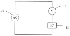
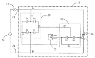
도 2는 본 공개의 실시예에 따른 단상 영구 자석 동기식 모터(10)의 개략적인 회로도를 도시한다. 모터의 스테이터 권선(16) 및 집적 회로(18)는 AC 교류 전원(24)의 2개의 단자 양단에서 직렬로 연결된다. 모터용 구동 회로는 집적 회로(18) 내로 집적되며 구동 회로는 모터에 전력이 공급될 때마다 고정된 방향으로 모터를 기동하게 할 수 있다.2 shows a schematic circuit diagram of a single phase permanent magnet
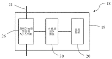
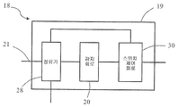
도 3은 집적 회로(18)의 구현 방식을 도시한다. 집적 회로는 하우징(19), 하우징(19) 밖으로 연장되는 2개의 핀(21) 및 하우징(19)에 패키징되는 구동 회로를 포함한다. 구동 회로는 반도체 기판상에 배치되며, 구동 회로는 모터의 로터의 자기장 극성을 감지하도록 구성되는 감지 회로(20), 2개의 핀(21) 사이에 연결되는 제어 가능한 양방향 교류 스위치(26) 및 감지 회로(20)에 의해 감지되는 로터의 자기장 극성을 기준으로 미리 설정된 방식으로 스위치 온 상태와 스위치 오프 상태 사이에서 스위칭되도록 제어 가능한 양방향 교류 스위치(26)를 제어하도록 구성되는 스위치 제어 회로(30)를 포함한다.FIG. 3 illustrates an implementation of the
바람직하게, 스위치 제어 회로(30)는 교류 전원(24)이 양의 반주기에 있고 로터의 자기장 극성이 제 1 극성인 것이 감지 회로(20)에 의해 감지되는 경우 또는 교류 전원(24)이 음의 반주기에 있고 로터의 자기장 극성이 제 1 극성에 반대되는 제 2 극성인 것이 감지 회로(20)에 의해 감지되는 경우에 제어 가능한 양방향 교류 스위치(26) 상에서 스위칭되도록 구성된다. 구조는 스테이터 권선(16)이 모터의 기동 단계에서 고정된 방향으로만 로터를 드래깅하는 것을 가능하게 한다.Preferably, the
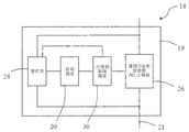
도 4는 집적 회로(18)의 구현 방식을 도시한다. 도 4는 도 4에 도시되는 집적 회로가 2개의 핀(21) 사이에서 제어 가능한 양방향 교류 스위치(26)와 병렬로 연결되는 정류기(28)를 더 포함하고 감지 회로(20)에 대하여 공급되는 직류를 생성할 수 있는 것에 있어서 도 3과 상이하다. 본 실시예에서, 바람직하게, 감지 회로(20)는 자기 센서(위치 센서로도 또한 지칭될 수 있음)가 될 수 있으며 집적 회로는 로터 근처에 설치되어서 자기 센서가 로터의 자기장 변화를 감지할 수 있다. 감지 회로(20)가 자기 센서를 포함할 수 없으며 로터의 자기장 변형은 다른 실시예들에서의 기타 방식으로 감지될 수 있는 것이 이해될 수 있다. 본 공개에 따른 실시예에서, 모터를 위한 구동 회로는 집적 회로에 패키징되므로 회로의 비용이 감소될 수 있으며 회로의 신뢰도가 향상될 수 있다. 또한, 모터는 PCB를 포함하지 않을 수 있으며 이것은 단순히 적절한 위치에 집적 회로를 고정하여 집적 회로를 인입선(leading wire)을 통해 모터의 전원 및 라인 그룹에 연결할 필요가 있다. Figure 4 illustrates an implementation of the
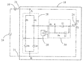
본 공개의 실시예에서, 스테이터 권선(16) 및 교류 전원(24)은 노드(A)와 노드(B) 사이에서 직렬로 연결된다. 바람직하게, 교류 전원(24)은 50Hz 또는 60Hz와 같은 고정 주파수를 갖는 상용 AC 전원이 될 수 있으며 공급 전압은 예컨대 110V, 220V 또는 230V이 될 수 있다. 제어 가능한 양방향 교류 스위치(26), 및 직렬로 연결되는 스테이터 권선(16) 및 교류 전원(24)은, 2개의 노드(A 및 B) 사이에서 병렬로 연결될 수 있다. 바람직하게, 제어 가능한 양방향 교류 스위치(26)는 3극관 AC 반도체 스위치(트라이액; TRIAC)가 될 수 있으며, 2개의 어노드는 각각 2개의 핀(21)에 연결된다. 제어 가능한 양방향 교류 스위치(26)는 역방향으로 병렬 연결되는 2개의 단방향 사이리스터를 포함하는 것 그리고 개별적인 제어 회로가 미리 설정된 방식으로 2개의 단방향 사이리스터를 제어하도록 배치될 수 있는 것이 이해될 수 있다. 정류기(28) 및 제어 가능한 양방향 교류 스위치(26)는 2개의 핀(21) 사이에서 병렬로 연결된다. 2개의 핀(21) 사이의 교류는 정류기(28)에 의해 저전압 직류로 변환된다. 감지 회로(20)는 정류기(28)에 의해 출력되는 저전압 직류에 의해 전력을 공급받을 수 있으며 동기식 모터(10)의 영구 자석 로터(11)의 자극 위치를 감지하고 상응하는 신호를 출력하도록 구성될 수 있다. 스위치 제어 회로(30)는 정류기(28), 감지 회로(20) 및 제어 가능한 양방향 교류 스위치(26)에 연결되며 정류기(28)로부터 얻어진 교류 전원(24)의 극성 및 감지 신호(20)에 의해 감지되는 영구 자석 로터의 자극 위치를 기초로 미리 설정된 방식으로 스위치 온 상태와 스위치 오프 상태 사이에서 스위칭되도록 제어 가능한 양방향 교류 스위치(26)를 제어하도록 구성되므로, 스테이터 권선(16)은 모터의 기동 단계에서 상기 언급된 고정 기동 방향으로만 로터(14)가 회전하도록 드래깅한다. 본 공개에 있어서, 제어 가능한 양방향 교류 스위치(26)가 스위치 온 될 경우, 2개의 핀(21)은 단락(short circuit)이며, 정류기(28)는 정류기(28)를 통해 흐르는 전류가 없으므로 전기 에너지를 소비하지 않으므로, 전기 에너지의 활용 효율이 상당히 개선될 수 있다. In the presently disclosed embodiment, the stator winding 16 and the
도 5는 실시예에 따른 도 2에 도시된 모터의 회로를 도시한다 모터의 스테이터 권선(16)은 집적 회로(18)의 2개의 핀(21) 사이에서 교류 전원(24)과 직렬로 연결된다. 2개의 노드(A 및 B)는 각각 2개의 핀(21)에 연결된다. 트라이액(26)의 제 1 어노드(T2)는 노드(A)에 연결되며 트라이액(26)의 제 2 어노드(T1)는 노드(B)에 연결된다. 정류기(28)는 2개의 노드(A 및 B)사이에서 트라이액(26)과 병렬로 연결된다. 2개의 노드(A 및 B) 사이의 교류 전압은 정류기(28)에 의해 낮은 직류 전압(DC)으로 전환된다(바람직하게, 낮은 전압은 3V에서 18V의 범위에 있음). 정류기(28)는 제 1 레지스터(R1)와 제 2 레지스터(R2) 및 제 1 제너 다이오드(Z1)와 제 2 제너 다이오드(Z2)를 포함하고, 이들은 2개의 노드(A 및 B) 사이에서 각각 제 1 레지스터(R1) 및 제 2 레지스터(R2)를 통해 역방향으로 병렬 연결된다. 정류기(28)의 고전압 출력 단자(C)는 제 1 레지스터(R1)와 제 1 제너 다이오드(Z1)의 캐소드의 연결 지점에서 형성되며, 정류기(28)의 저전압 출력 단자(D)는 제 2 레지스터(R2)와 제 2 제너 다이오드(Z2)의 어노드의 연결 지점에서 형성된다. 전압 출력 단자(C)는 위치 센서(20)의 양의 전원 단자에 연결되며 전압 출력 단자(D)는 위치 센서(20)의 음의 전원 단자에 연결된다. 스위치 제어 회로(30)의 3개의 단자는 각각 정류기(28)의 전압 출력 단자(C), 위치 센서(20)의 출력 단자(H1) 및 트라이액(26)의 제어 전극(G)에 연결된다. 스위치 제어 회로(30)는 위치 센서(20)의 출력 단자(H1)와 제어 가능한 양방향 교류 스위치(26)의 제어 전극(G) 사이에서 직렬로 연결되는 제 3 레지스터(R3), 제 5 다이오드(D5), 및 제 4 레지스터(R4) 및 제 6 다이오드(D6)를 포함한다. 제 6 다이오드(D6)의 어노드는 제어 가능한 양방향 교류 스위치(26)의 제어 전극(G)에 연결된다. 제 3 레지스터(R3)의 하나의 단자는 정류기(28)의 고전압 출력 단자(C)에 연결되며 제 3 레지스터(R3)의 다른 단자는 제 5 다이오드(D5)의 어노드에 연결된다. 제 5 다이오드(D5)의 캐소드는 제어 가능한 양방향 교류 스위치(26)의 제어 전극(G)에 연결된다.Figure 5 shows the circuit of the motor shown in Figure 2 according to an embodiment. The motor's stator winding 16 is connected in series with an
도 6을 참조하여, 상기 기재된 회로의 동작 원리가 기재된다. 도 6에서, Vac는 교류 전원(24)의 전압의 파형을 표시하며, Iac는 스테이터 권선(16)을 통해 흐르는 전류의 파형을 표시한다. 스테이터 권선(16)의 유도 특징으로 인해, 전류 Iac의 파형은 전압 Vac의 파형보다 뒤떨어진다(lags behind). V1는 제너 다이오드(Z1)의 2개의 단자 사이에서 전압의 파형을 표시하고, V2는 제너 다이오드(Z2)의 2개의 단자 사이에서 전압의 파형을 표시하고, Vcd는 정류기(28)의 2개의 출력 단자(C 및 D) 사이의 전압의 파형을 표시하고, Ha는 위치 센서(20)의 출력 단자(H1)로부터 출력된 신호의 파형을 표시하며, Hb는 위치 센서(20)에 의해 감지되는 로터 자기장을 표시한다. 본 실시예에서, 위치 센서(20)에 정상적으로 전력이 공급되는 경우, 출력 단자(H1)는 감지된 로터 자기장이 노스(North)인 경우 논리 고레벨을 출력하고 또는 출력 단자(H1)는 감지된 로터 자기장이 사우스(South)인 경우 논리 저레벨을 출력한다. Referring to Fig. 6, the operation principle of the circuit described above will be described. In Fig. 6, Vac indicates the waveform of the voltage of the
위치 센서(20)에 의해 감지되는 로터 자기장(Hb)이 노스일 때, 교류 전원의 제 1 양의 반주기에서, 공급 전압은 순시치(t0)에서 순시치(t1)로의 기간에서 점진적으로 증가되고, 위치 센서(20)의 출력 단자(H1)는 고레벨을 출력하며, 전류는 레지스터(R1), 레지스터(R3), 다이오드(D5) 및 트라이액(26)의 제 2 어노드(T1) 및 제어 전극(G)을 통해 순차적으로 흐른다. 트라이액(26)은 제어 전극(G)과 제 2 어노드(T1)를 통해 흐르는 구동 전류가 게이트 구동 전류(Ig)보다 더 클 때 스위치 온 된다. 트라이액(26)이 스위치 온 되면, 2개의 노드(A 및 B)는 단락이며, 모터의 스테이터 권선(16)을 통해 흐르는 전류는 큰 순방향 전류가 스테이터 권선(16)를 통해 흐를 때까지 점진적으로 증가되며 로터(14)는 도 3에 도시된 바와 같이 시계방향으로 회전하도록 구동된다. 2개의 노드(A 및 B)가 단락이므로, 순시치(t1)로부터 순시치(t2)로의 시간 기간동안 정류기(28)를 통해 흐르는 전류가 존재하지 않는다. 그러므로, 레지스터(R1 및 R2)는 전기 에너지를 소비하지 않으며 위치 센서(20)의 출력은 전원 전압의 부재로 인하여 중단된다. 트라이액(26)의 2개의 어노드(T1 및 T2)를 통해 흐르는 충분히 큰 전류가 존재하므로(유지 전류(Ihold)보다 더 큼), 트라이액(26)은 제어 전극(G)과 제 2 어노드(T1)를 통해 흐르는 구동 전류가 없을 때 스위치 온 되어 유지된다. 교류 전원의 음의 반주기에서, 순시치(t3) 후에, T1 및 T2를 통해 흐르는 전류는 유지 전류(Ihold)보다 작고, 트라이액(26)은 스위치 오프되어서, 구동 전류는 정류기(28)를 통해 흐르기 기동하며 위치 센서(20)의 출력 단자(H1)는 고레벨을 다시 출력한다. 지점(C)에서의 전위가 지점(E)에서의 전위보다 더 낮기 때문에, 트라이액(26)의 제어 전극(G)과 제 2 어노드(T1)를 통해 흐르는 구동 전류는 존재하지 않으며, 트라이액(26)은 스위치 오프되어 유지된다. 정류기(28)의 레지스터(R1 및 R2)의 저항이 모터의 스테이터 권선(16)의 저항보다 훨씬 크기 때문에, 스테이터 권선(16)을 통해 현재 흐르는 전류는 순시치(t1)에서 순시치(t2)로의 시간의 기간에서 스테이터 권선(16)을 통해 흐르는 전류보다 훨씬 작고, 로터(14)를 위한 구동력은 존재하지 않는다. 따라서, 로터(14)는 관성 효과로 인해 시계 방향으로 회전을 계속한다. 교류 전원의 제 2 양의 반주기에서, 제 1 양의 반주기와 마찬가지로, 전류는 레지스터(R1), 레지스터(R3), 다이오드(D5), 및 트라이액(26)의 제어 전극(G) 및 제 2 어노드(T1)를 통해 순차적으로 흐른다. 트라이액(26)은 다시 스위치 온 되고, 스테이터 권선(16)을 통해 흐르는 전류는 로터(14)가 시계방향으로 회전하도록 계속 구동한다. 유사하게, 레지스터(R1 및 R2)는 2개의 노드(A 및 B)가 단락이므로 전기 에너지를 소비하지 않고, 전원의 음의 반주기에서, 트라이액(26)의 2개의 노드(T1 및 T2)를 통해 흐르는 전류는 유지 전류(Ihold) 보다 작으며, 트라이액(26)은 다시 스위치 오프 되므로 로터는 관성 효과로 인하여 시계방향으로 계속 회전한다. When the rotor magnetic field Hb sensed by the
순시치(t4)에서, 위치 센서(20)에 의해 감지되는 로터 자기장(Hb)이 사우스에서 노스가 되게 변경되므로, 교류 전원은 양의 반주기에 있으며 트라이액(26)은 스위치 온되고, 2개의 노드(A 및 B)가 단락이며 정류기(28)를 통해 흐르는 전류가 존재하지 않는다. 교류 전원이 음의 반주기에 존재한 후, 트라이액(26)의 2개의 어노드(T1 및 T2)를 통해 흐르는 전류는 점진적으로 감소되며 트라이액(26)은 순시치(t5)에서 스위치 오프된다. 이로써, 전류는 트라이액(26)의 제 2 어노드(T1) 및 제어 전극(G), 다이오드(D6), 레지스터(R4), 위치 센서(20), 레지스터(R2) 및 스테이터 권선(16)을 통해 순차적으로 흐른다. 구동 전류가 점진적으로 증가되면, 트라이액(26)은 순시치(t6)에서 다시 스위치 온 되고, 2개의 노드(A 및 B)는 다시 단락이고, 레지스터(R1 및 R2)는 전기 에너지를 소비하지 않으며 위치 센서(20)의 출력은 전원 전압이 존재하지 않기 때문에 중단된다. 스테이터 권선(16)을 통해 흐르는 큰 역전류가 존재하며 로터(14)는 로터 자기장이 사우스이므로 시계방향으로 구동되도록 계속된다. 순시치(t5)에서 순시치(t6)으로의 시간의 기간에서, 제 1 제너 다이오드(Z1) 및 제 2 제너 다이오드(Z2)는 스위치 온 되므로, 정류기(28)의 2개의 출력 단자(C 및 D) 사이에서 출력된 전압이 존재한다. 순시치(t7)에서, 교류 전원이 다시 양의 반주기에 존재하고, 트라이액(26)은 트라이액(26)을 통해 흐르는 전류가 제로를 넘으면 스위치 오프되며 이로써 제어 회로의 전압이 점진적으로 증가된다. 전압이 점진적으로 증가되면, 전류는 정류기(28)를 통해 흐르기 시작하고, 위치 센서(20)의 출력 단자(H1)는 저레벨 신호를 출력하고, 트라이액(26)의 제어 전극(G) 및 제 2 어노드(T1)를 통해 흐르는 구동 전류는 존재하지 않으므로, 트라이액(26)이 스위치 오프된다. 스테이터 권선(16)을 통해 흐르는 전류가 작기 때문에, 구동력은 로터(14)를 위하여 생성되지 않는다. 순시치(t8)에서, 전원은 양의 반주기에 있고, 위치 센서는 저레벨 신호를 출력하며, 트라이액(26)은 전류가 제로를 넘은 후에 스위치 오프되어 유지되며 로터는 관성 효과로 인해 시계 방향으로 계속 회전한다. 본 공개에 있어서, 로터는 스테이터 권선에 전력이 공급된 후 단 하나의 서클을 회전함으로써 스테이터의 필드와 동기화되도록 가속화될 수 있다.At instantaneous value t4, the rotor magnetic field Hb sensed by the
본 공개의 실시예에 따른 회로 교류에 의해, 모터는 모터에 전력이 공급될 때마다 동일한 방향으로 기동하고 회전되도록 보장될 수 있다. 이러한 블로워 및 워터 펌프와 같은 응용에서, 로터에 의해 구동되는 팬 블레이드 및 임펠러(impeller)는 곡선 날개(curved vane)를 가질 수 있으므로 블로워 및 워터 펌프의 효율이 개선된다. 또한, 본 공개의 실시예에서, 트라이액이 트라이액을 따라 흐르는 구동 전류 없이 스위치 온 되어 유지되는 트라이액의 특성을 이용하여, 트라이액이 스위치 온 되면, 정류기(28)의 레지스터(R1) 및 레지스터(R2)는 트라이액이 스위치 온 된 후에 전기 에너지를 여전히 소비되는 것을 회피되므로, 전기 에너지의 활용 효율이 상당히 개선될 수 있다.By circuit alternating according to the embodiment of the present disclosure, the motor can be ensured to be started and rotated in the same direction each time power is supplied to the motor. In applications such as blowers and water pumps, the fan blades and impellers driven by the rotor can have curved vanes, thus improving the efficiency of the blower and water pump. Further, in the embodiment of the present disclosure, when the triac is switched on using the characteristics of the triac that the triac is kept switched on without the driving current flowing along the triac, the resistors R1 and R2 of the
도 7은 실시예에 따른 도 2에 도시된 모터의 회로를 도시한다. 모터의 스테이터 권선(16)은 집적 회로(18)의 2개의 핀(21) 사이에서 교류 전원(24)과 직렬로 연결된다. 2개의 노드(A 및 B)는 개별적으로 2개의 핀(21)에 연결된다. 트라이액(26)의 제 1 어노드(T2)는 노드(A)에 연결되며, 트라이액(26)의 제 2 어노드(T1)는 노드(B)에 연결된다. 정류기(28)는 2개의 노드(A 및 B) 사이에서 트라이액(26)와 병렬로 연결된다. 2개의 노드(A 및 B) 사이의 교류는 정류기(28)에 의해 저전압 직류로 변환되며, 바람직하게, 저전압은 3V에서 18V의 범위에 있다. 정류기(28)는 2개의 노드(A 및 B)사이에 직렬로 연결되는 전파 브릿지 정류기 및 제 1 레지스터(R1)를 포함한다. 제 1 레지스터(R1)는 전압 강하기로서 사용될 수 있으며 전파 브릿지 정류기는 병렬로 연결되는 2개의 정류기 브랜치를 포함하고, 2개의 정류기 브랜치 중 하나는 역방향으로 직렬 연결되는 제 1 다이오드(D1) 및 제 3 다이오드(D3)를 포함하고, 2개의 정류기 브랜치 중 다른 하나는 역방향으로 직렬 연결되는 제 2 제너 다이오드(Z2) 및 제 4 제너 다이오드(Z4)를 포함하고, 정류기(28)의 고전압 출력 단자(C)는 제 1 다이오드(D1)의 캐소드와 제 3 다이오드(D3)의 캐소드의 연결 지점에서 형성되며, 정류기(28)의 저전압 출력 단자(D)는 제 2 제너 다이오드(Z2)의 어노드와 제 4 제너 다이오드(Z4)의 어노드의 연결 지점에서 형성된다. 출력 단자(C)는 위치 센서(20)의 양의 전원 단자에 연결되며 출력 단자(D)는 위치 센서(20)의 음의 전원 단자에 연결된다. 스위치 제어 회로(30)는 위치 센서(20)의 출력 단자(H1)와 제어 가능한 양방향 교류 스위치(26)의 제어 전극(G) 사이에서 역방향으로 직렬 연결되는 제 3 레지스터(R3), 제 4 레지스터(R4), 및 제 5 다이오드(D5) 및 제 6 다이오드(D6)를 포함한다. 제 5 다이오드(D5)의 캐소드는 위치 센서의 출력 단자(H1)에 연결되며 제 6 다이오드(D6)의 캐소드는 제어 가능한 양방향 교류 스위치의 제어 전극(G)에 연결된다. 제 3 레지스터(R3)의 하나의 단자가 정류기의 고전압 출력 단자(C)에 연결되며 제 3 레지스터(R3)의 다른 하나의 단자는 제 5 다이오드(D5)의 어노드와 제 6 다이오드(D6)의 어노드의 연결 지점에서 연결된다. 제 4 레지스터(R4)의 2개의 단자는 제 5 다이오드(D5)의 캐소드와 제 6 다이오드(D6)의 캐소드에 각각 연결된다. Fig. 7 shows a circuit of the motor shown in Fig. 2 according to the embodiment. The stator winding 16 of the motor is connected in series with the
도 8은 실시예에 따라 도 2에 도시된 모터의 회로를 도시한다. 실시예는 도 7의 제너 다이오드(Z2 및 Z4)가 도 8의 정류기의 일반적인 다이오드(D2 및 D4)에 의해 교체되는 것에 있어서 이전 실시예와 상이하다. 또한, 제너 다이오드(Z7)는 도 8에서 정류기(28)의 2개의 출력 단자(C 및 D) 사이에 연결된 전압 레귤레이터로서 사용된다. Fig. 8 shows the circuit of the motor shown in Fig. 2 according to the embodiment. The embodiment differs from the previous embodiment in that the Zener diodes Z2 and Z4 of Fig. 7 are replaced by the general diodes D2 and D4 of the rectifier of Fig. The zener diode Z7 is also used as a voltage regulator connected between the two output terminals C and D of the
도 9는 실시예에 따른 도 2에 도시된 모터의 회로를 도시한다. 동기식 모터의 스테이터 권선(16)은 집적 회로(18)의 2개의 핀(21)에서 교류 전원(24)과 직렬 연결된다. 2개의 노드(A 및 B)는 각각 2개의 핀(21)에 연결된다. 트라이액(26)의제 1 어노드(T2)는 노드(A)에 연결되며 트라이액(26)의 제 2 어노드(T1)는 노드(B)에 연결된다. 정류기(28)는 2개의 노드(A 및 B) 사이에서 트라이액(26)과 병렬로 연결된다. 2개의 노드(A 및 B) 사이의 교류는 정류기(28)에 의해 저전압 직류로 변환되며, 바람직하게, 저전압은 3V에서 18V의 범위에 있다. 정류기(28)는 2개의 노드(A 및 B)사이에 직렬로 연결되는 전파 브릿지 정류기 및 제 1 레지스터(R1)를 포함한다. 제 1 레지스터(R1)는 전압 강하기로서 사용될 수 있다. 전파 브릿지 정류기는 병렬로 연결되는 2개의 정류기 브랜치를 포함하고, 2개의 정류기 브랜치 중 하나는 역방향으로 직렬 연결되는 2개의 실리콘 제어된 정류기(S1 및 S3)를 포함하며, 2개의 정류기 브랜치 중 다른 하나는 역방향으로 직렬 연결되는 제 2 다이오드(D2) 및 제 4 다이오드(D4)를 포함한다. 정류기(28)의 고전압 출력 단자(C)는 실리콘 제어된 정류기(S1)의 캐소드와 실리콘 제어된 정류기(S3)의 캐소드의 연결 지점에 형성되며, 정류기(28)의 저전압 출력 단자(D)는 제 2 다이오드(D2)의 어노드와 제 4 다이오드(D4)의 어노드의 연결 지점에서 형성된다. 출력 단자(C)는 위치 센서(20)의 양의 전원 단자에 연결되며, 출력 단자(D)는 위치 센서(20)의 음의 전원 단자에 연결된다. 스위치 제어 회로(30)는 위치 센서(20)의 출력 단자(H1)와 제어 가능한 양방향 교류 스위치(26)의 제어 전극(G) 사이에 직렬로 연결되는 제 3 레지스터(R3), NPN 삼극관(T6), 및 제 4 레지스터(R4) 및 제 5 다이오드(D5)를 포함한다. 제 5 다이오드(D5)의 캐소드는 위치 센서의 출력 단자(H1)에 연결된다. 제 3 레지스터(R3)의 하나의 단자는 정류기의 고전압 출력 단자(C)에 연결되며, 제 3 레지스터(R3)의 다른 단자는 위치 센서의 출력 단자(H1)에 연결된다. NPN 삼극관(T6)의 베이스는 위치 센서의 출력 단자(H1)에 연결되고, NPN 삼극관(T6)의 방출기는 제 5 다이오드(D5)의 어노드에 연결되며 NPN 삼극관(T6)의 콜렉터는 정류기의 고전압 출력 단자(C)에 연결된다. Fig. 9 shows a circuit of the motor shown in Fig. 2 according to the embodiment. The stator winding 16 of the synchronous motor is connected in series with the
본 실시예에서, 기준 전압은 단자(SC1)를 통해 2개의 실리콘 제어된 정류기(S1 및 S3)의 캐소드들에 입력될 수 있으며 제어 신호는 단자(SC2)를 통해 2개의 제어 단자(S1 및 S3)내에 입력된다. S1 및 S3는 단자(SC2)로부터 입력된 제어 신호가 고레벨인 경우에 스위치 온 되고 또는 S1 및 S3은 단자(SC2)로부터 입력된 제어 신호가 고레벨인 경우에 구동 전류의 부재로 인해 스위치 오프된다. 구조를 기초로, S1 및 S3는 구동 회로가 정상적으로 작동하는 경우에 단자(SC2)로부터 고레벨을 입력함으로써 미리 정해진 방식으로 스위치 온 상태와 스위치 오프 상태 사이에서 스위칭될 수 있다. S1 및 S3는 모터가, 구동 회로가 실패(fail)할 경우, 고레벨에서 저레벨로의 단자(SC2)로부터 입력된 제어 신호를 변경함으로써 스위치 오프된다. 이러한 경우에, 트라이액(26), 정류기(28) 및 위치 센서(20)는 전체 회로가 제로 파워 상태에 있는 것을 보장하도록 스위치 오프된다.In this embodiment, the reference voltage can be input to the cathodes of the two silicon controlled rectifiers S1 and S3 via the terminal SC1 and the control signal is transmitted via the terminal SC2 to the two control terminals S1 and S3 . S1 and S3 are switched on when the control signal input from the terminal SC2 is high, or S1 and S3 are switched off due to the absence of the driving current when the control signal input from the terminal SC2 is high. On the basis of the structure, S1 and S3 can be switched between a switch-on state and a switch-off state in a predetermined manner by inputting a high level from the terminal SC2 when the drive circuit is normally operated. S1 and S3 are switched off by changing the control signal input from the terminal SC2 from the high level to the low level when the motor fails the driving circuit. In this case, the
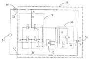
도 10은 본 공개의 실시예에 따른 단상 영구 자석 동기식 모터(10)의 개략적인 회로도를 도시한다. 모터의 스테이터 권선(16)은 교류 전원(24)의 2개의 단자 사이에서 집적 회로(18)와 직렬로 연결된다. 모터를 위한 구동 회로는 집적 회로(18)내에 집적되며 구동 회로는 모터에 전력이 공급될 때마다 고정된 방향으로 모터를 기동할 수 있게 한다. 본 공개에서, 모터용 구동 회로는 집적회로 내에 패키징되므로 회로의 비용이 감소될 수 있으며 회로의 신뢰도가 개선될 수 있다.10 shows a schematic circuit diagram of a single phase permanent
본 공개에서, 실제 상황을 기반으로, 정류기, 감지 회로, 스위치 제어 회로, 제어 가능한 양방향 교류 스위치의 전부 또는 일부는 집적 회로 내에 집적될 수 있다. 예컨대, 도 3에 도시된 바와 같이, 감지 회로, 스위치 제어 회로 및 제어 가능한 양방향 교류 스위치만이 집적 회로 내에 집적되며 정류기는 집적 회로 외부에 배치된다.In the present disclosure, all or part of the rectifier, sense circuit, switch control circuit, controllable bidirectional ac switch may be integrated in the integrated circuit, based on the actual situation. For example, as shown in Fig. 3, only the sensing circuit, the switch control circuit and the controllable bidirectional ac switch are integrated in the integrated circuit, and the rectifier is disposed outside the integrated circuit.
예컨대, 도 10 및 도 11의 실시예에 도시된 바와 같이, 전압 강하 회로(32) 및 제어 가능한 양방향 교류 스위치(26)는 집적 회로 외부에 배치되며, 정류기(정류기 브릿지 만을 포함하되 전압 강하 레지스터 또는 기타 전압 강하 부품은 포함하지 않음), 감지 회로 및 스위치 제어 회로는 집적 회로 내에 집적된다. 본 실시예에서, 저전력부는 집적 회로 내에 집적되며, 전압 강하 회로(32)는 고 전력부와 같은 제어 가능한 양방향 교류 스위치(26)는 집적 회로의 외부에 배치된다. 도 12에 도시된 실시예에서, 전압 강하 회로(32)는 집적 회로 내로 집적될 수 있으며, 제어 가능한 양방향 교류 스위치는 집적 회로 외부에 배치된다. For example, as shown in the embodiment of FIGS. 10 and 11, the
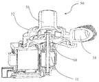
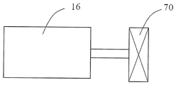
도 13은 상기 기재된 모터를 사용하는 워터 펌프(50)를 도시한다. 워터 펌프(50)는 펌프 챔버(52)를 갖는 펌프 하우징(54), 펌프 챔버와 통하는 입구(56) 및 출구(58), 펌프 챔버에 회전 가능하게 배치되는 임펠러(60) 및 임펠러를 구동하도록 구성되는 모터 어셈블리를 포함한다. 도 14는 상기 기재된 모터를 사용하는 블로워를 도시한다. 블로워는 팬 블레이드(70)를 포함하며 팬 블레이드(70)는 모터(16)의 출력 축을 통해 직/간접적으로 구동된다.13 shows a
상기 기재된 것은 오직 본 공개의 선호되는 실시예이며 본 공개의 보호의 범위를 한정하도록 의도되지 않는다. 본 공개의 정신 및 원칙 내에서 만들어지는 임의의 변화, 균등한 대체물, 개선점 등이 본 공개의 보호의 범위 내에 모두 포함된다. 예컨대, 본 공개의 구동 회로는 단상 영구 자석 동기식 모터에 적용될 뿐만 아니라, 단상 브러시리스(brushless) DC 모터와 같은 영구 자석 모터의 기타 형태에 적용된다.What has been described above is the preferred embodiment of this disclosure only and is not intended to limit the scope of protection of this disclosure. Any alterations, equivalent replacements, improvements, etc., made within the spirit and principle of this disclosure are all included within the scope of protection of this disclosure. For example, the drive circuit of the present disclosure applies not only to single-phase permanent magnet synchronous motors, but also to other forms of permanent magnet motors such as single-phase brushless DC motors.
Claims (17)
상기 스테이터 권선과 직렬로 연결되고 상기 AC 전원의 2개의 단자 사이에 연결되도록 구성되는 제어가능한 양방향 AC 스위치;
상기 영구 자석 로터의 자기장 극성을 감지하도록 구성된 감지 회로; 및
상기 AC 전원의 극성 및 상기 감지 회로에 의해 감지된 상기 영구 자석 로터의 상기 자기장 극성을 기초로, 미리 결정된 방식으로 스위치 온 상태와 스위치 오프 상태 사이에서 스위칭되도록 제어가능한 양방향 AC 스위치를 제어하도록 구성되는 스위치 제어 회로를 포함하는, 모터 어셈블리.The driving circuit according to claim 1,
A controllable bidirectional AC switch coupled in series with the stator winding and configured to be coupled between two terminals of the AC power source;
A sensing circuit configured to sense a magnetic field polarity of the permanent magnet rotor; And
And to control a bidirectional AC switch controllable to switch between a switched on state and a switched off state in a predetermined manner based on the polarity of the AC power source and the magnetic pole polarity of the permanent magnet rotor sensed by the sensing circuit And a switch control circuit.
Applications Claiming Priority (5)
| Application Number | Priority Date | Filing Date | Title |
|---|---|---|---|
| CN201410390592.2 | 2014-08-08 | ||
| CN201410390592 | 2014-08-08 | ||
| CN201410404474.2A CN107634683B (en) | 2014-08-08 | 2014-08-15 | Synchronous motor drive circuit |
| CN201410404474.2 | 2014-08-15 | ||
| PCT/CN2015/086423 WO2016019922A1 (en) | 2014-08-08 | 2015-08-07 | Fan, pump, motor assembly and integrated circuit for motor drive |
Publications (1)
| Publication Number | Publication Date |
|---|---|
| KR20170039728A true KR20170039728A (en) | 2017-04-11 |
Family
ID=53783646
Family Applications (3)
| Application Number | Title | Priority Date | Filing Date |
|---|---|---|---|
| KR1020177006374A KR20170039740A (en) | 2014-08-08 | 2015-08-07 | Motor assembly and integrated circuit for motor drive |
| KR1020177006216A KR20170039728A (en) | 2014-08-08 | 2015-08-07 | Fan, pump, motor assembly and integrated circuit for motor drive |
| KR1020150111708A KR20160018434A (en) | 2014-08-08 | 2015-08-07 | Drive circuit for a permanent magnet motor |
Family Applications Before (1)
| Application Number | Title | Priority Date | Filing Date |
|---|---|---|---|
| KR1020177006374A KR20170039740A (en) | 2014-08-08 | 2015-08-07 | Motor assembly and integrated circuit for motor drive |
Family Applications After (1)
| Application Number | Title | Priority Date | Filing Date |
|---|---|---|---|
| KR1020150111708A KR20160018434A (en) | 2014-08-08 | 2015-08-07 | Drive circuit for a permanent magnet motor |
Country Status (10)
| Country | Link |
|---|---|
| US (4) | US9755555B2 (en) |
| EP (1) | EP2983288B1 (en) |
| JP (14) | JP2017529057A (en) |
| KR (3) | KR20170039740A (en) |
| CN (17) | CN107251405B (en) |
| BR (1) | BR102015019000B1 (en) |
| DE (2) | DE112015003676T5 (en) |
| MX (3) | MX2017001793A (en) |
| TW (6) | TWM547783U (en) |
| WO (2) | WO2016019922A1 (en) |
Families Citing this family (20)
| Publication number | Priority date | Publication date | Assignee | Title |
|---|---|---|---|---|
| MX2017001793A (en) * | 2014-08-08 | 2017-04-27 | Johnson Electric Sa | Fan, pump, motor assembly and integrated circuit for motor drive. |
| EP3135937A1 (en) * | 2015-08-14 | 2017-03-01 | Johnson Electric S.A. | Electric apparatus, actuator and clutch thereof |
| CN106469958A (en) * | 2015-08-14 | 2017-03-01 | 德昌电机(深圳)有限公司 | Fluid generating device |
| CN107231062A (en) * | 2016-03-24 | 2017-10-03 | 德昌电机(深圳)有限公司 | The wind cooling refrigerator of cooling fan and the application cooling fan |
| DE102017106426A1 (en) * | 2016-03-28 | 2017-09-28 | Johnson Electric S.A. | Motor, stand and method for forming the stator |
| DE102016118501A1 (en) | 2016-09-29 | 2018-03-29 | Miele & Cie. Kg | Two-strand single-phase synchronous drive |
| WO2018183783A1 (en) * | 2017-03-29 | 2018-10-04 | Qm Power, Inc. | Multispeed alternating current motor |
| CN108696057B (en) * | 2017-04-12 | 2021-06-25 | 德昌电机(深圳)有限公司 | Motor and electric equipment with same |
| CN109687780A (en) * | 2017-08-25 | 2019-04-26 | 德昌电机(深圳)有限公司 | Motor and its driving circuit and driving method |
| CN109672373A (en) * | 2017-08-25 | 2019-04-23 | 德昌电机(深圳)有限公司 | Motor and its driving circuit and driving method |
| CN109842330B (en) * | 2017-11-24 | 2021-12-14 | 南京德朔实业有限公司 | Control method of single-phase brushless motor |
| DE102017223061A1 (en) * | 2017-12-18 | 2019-06-19 | Bühler Motor GmbH | COMMUTATOR ENGINE AND SERIES OF COMMUTATOR MOTORS |
| JP7061457B2 (en) | 2017-12-22 | 2022-04-28 | ローム株式会社 | Magnetic sensors, semiconductor devices and electrical equipment |
| CN111226626B (en) * | 2018-11-28 | 2022-09-16 | 南京泉峰科技有限公司 | Chain saw, electric tool, and control method for electric tool |
| CN109921770A (en) * | 2019-03-07 | 2019-06-21 | 维沃移动通信有限公司 | A kind of motor drive circuit and terminal device |
| US20230042503A1 (en) * | 2020-04-25 | 2023-02-09 | Normand BUSSIÈRES | Electric motors and methods of controlling thereof |
| IT202000016672A1 (en) * | 2020-07-09 | 2022-01-09 | De Longhi Appliances Srl | METHOD AND CONTROL CIRCUIT FOR A DIRECT CURRENT MOTOR |
| CN111856337A (en) * | 2020-07-10 | 2020-10-30 | 海信集团有限公司 | Control circuit, control panel, electric equipment and control method |
| US11424709B2 (en) * | 2020-11-05 | 2022-08-23 | Raptor Lift Solutions, Llc | Method and apparatus for riding through power disruptions of a drive circuit |
| CN114485738B (en) * | 2022-01-06 | 2024-01-12 | 天津中德应用技术大学 | Double-group Hall sensor device and control method thereof |
Family Cites Families (52)
| Publication number | Priority date | Publication date | Assignee | Title |
|---|---|---|---|---|
| US3056896A (en) * | 1958-11-10 | 1962-10-02 | Licentia Gmbh | Stator for a.c. motor |
| US3596159A (en) * | 1968-03-22 | 1971-07-27 | Janome Sewing Machine Co Ltd | Speed control circuit for a single-phase motor,using a thyristor |
| JPS48102222A (en) * | 1972-04-12 | 1973-12-22 | ||
| DE2407601C2 (en) * | 1974-02-16 | 1980-04-17 | Robert Bosch Gmbh, 7000 Stuttgart | Control device for lowering the speed of an AC-fed series motor in idle mode |
| US4896105A (en) * | 1988-03-25 | 1990-01-23 | Westinghouse Electric Corp. | AC electric energy meter having drive circuit including stepper motor for driving mechanical register |
| US4949214A (en) * | 1989-08-28 | 1990-08-14 | Spencer George A | Trip delay override for electrical circuit breakers |
| US6348752B1 (en) * | 1992-04-06 | 2002-02-19 | General Electric Company | Integral motor and control |
| US5682459A (en) * | 1995-07-27 | 1997-10-28 | Wilkerson; Alan W. | Speed control for controlling the speed of a DC motor |
| US5675226A (en) * | 1995-09-06 | 1997-10-07 | C.E.Set. S.R.L. | Control circuit for an synchronous electric motor of the brushless type |
| JP3555297B2 (en) * | 1996-02-06 | 2004-08-18 | 松下電器産業株式会社 | Power generator and vacuum cleaner as its application equipment |
| US6118427A (en) * | 1996-04-18 | 2000-09-12 | Silicon Graphics, Inc. | Graphical user interface with optimal transparency thresholds for maximizing user performance and system efficiency |
| US6097127A (en) * | 1996-08-22 | 2000-08-01 | Rivera; Nicholas N. | Permanent magnet direct current (PMDC) machine with integral reconfigurable winding control |
| JPH1084685A (en) * | 1996-09-06 | 1998-03-31 | Tominaga Jushi Kogyosho:Kk | Controller for rotational direction of two-pole ac motor |
| JPH10117495A (en) * | 1996-10-09 | 1998-05-06 | Higashifuji Manuf Ltd | Reversible motor |
| IT1289817B1 (en) * | 1996-12-30 | 1998-10-16 | Plaset Srl | DEVICE FOR CONTROL OF A SYNCHRONOUS ELECTRIC MOTOR WITH PERMANENT MAGNET ROTOR |
| JPH10337065A (en) * | 1997-06-03 | 1998-12-18 | Techno Takatsuki:Kk | Synchronous motor |
| JP3446692B2 (en) * | 1999-11-24 | 2003-09-16 | 三菱電機株式会社 | Control device for single-phase motor, actuator and blower using control device for single-phase motor |
| KR100367478B1 (en) * | 2000-12-15 | 2003-01-10 | 김준 | Fabrication Method of Stator Assembly Using Slotless Stator Core on Brushless DC Motor and Brushless DC Motor Thereby |
| DE10103845B4 (en) * | 2001-01-30 | 2006-11-16 | Ontoprise Gmbh | computer system |
| EP1351375B1 (en) * | 2002-03-05 | 2004-09-01 | Askoll Holding S.r.l. | Permanent-magnet synchronous motor with an electronic device for starting the motor and with sensor means which position is dependent on the load driven by the motor |
| US6767817B2 (en) * | 2002-07-11 | 2004-07-27 | Micron Technology, Inc. | Asymmetric plating |
| JP4053840B2 (en) * | 2002-08-26 | 2008-02-27 | 富士通株式会社 | Semiconductor integrated circuit |
| JP2004153906A (en) * | 2002-10-29 | 2004-05-27 | Asahi Kasei Microsystems Kk | Device for preventing reverse connection |
| CN2622928Y (en) * | 2003-05-08 | 2004-06-30 | 建准电机工业股份有限公司 | Speed control circuit of d.c. brushless fan motor |
| ITMI20031661A1 (en) * | 2003-08-22 | 2005-02-23 | Askoll Holding Srl | ELECTRONIC IGNITION AND SHUTDOWN DEVICE FOR |
| JP2005245167A (en) * | 2004-02-27 | 2005-09-08 | Matsushita Electric Ind Co Ltd | Dc power supply unit |
| US7208907B2 (en) * | 2004-10-21 | 2007-04-24 | Shop Vac Corporation | System and method of restarting a switched reluctance motor after a rapid cycling of power |
| JP4691376B2 (en) * | 2005-03-25 | 2011-06-01 | 山洋電気株式会社 | Permanent magnet type rotary motor |
| US20070103103A1 (en) * | 2005-11-09 | 2007-05-10 | Maue H W | Bi-directional motor voltage conversion circuit |
| US7173388B1 (en) * | 2005-11-14 | 2007-02-06 | Power Logic Tech. Inc. | Drive control device for brushless motor |
| US7536860B2 (en) * | 2006-05-25 | 2009-05-26 | Thermotion Corporation | Thermo-magnetic actuator |
| US7622876B2 (en) * | 2006-07-31 | 2009-11-24 | Danaher Motion, Llc | Overload prevention device for permanent magnet DC motors |
| NZ549662A (en) * | 2006-09-04 | 2009-01-31 | Wellington Drive Technologies | Control of synchronous electrical machines |
| CN101174804A (en) * | 2006-10-31 | 2008-05-07 | 德昌电机股份有限公司 | Electric start controlling equipment for synchronous motor |
| DE102006055482A1 (en) | 2006-11-24 | 2008-06-12 | Hanning Elektro-Werke Gmbh & Co. Kg | Method for electronic control of synchronous motor, particularly single phase synchronous motor with permanent magnetic rotor, involves energizing permanent magnetic rotor by alternating voltage switch |
| JP5150276B2 (en) * | 2008-01-25 | 2013-02-20 | パナソニック株式会社 | Insulator structure of motor |
| US7791232B2 (en) * | 2008-05-02 | 2010-09-07 | Black & Decker Inc. | Power tool having an electronically commutated motor and double insulation |
| CN101662205B (en) * | 2008-08-27 | 2013-07-10 | 德昌电机(深圳)有限公司 | Boost-buck accelerating circuit |
| JP4823294B2 (en) * | 2008-11-04 | 2011-11-24 | 三菱電機株式会社 | Blower and heat pump device using this blower |
| CN201409107Y (en) * | 2009-03-12 | 2010-02-17 | 敬石桥 | AC motor control circuit and AC synchronous water pump |
| GB0908111D0 (en) * | 2009-05-12 | 2009-06-24 | Peto Raymond J | A motor controller & related method |
| CN201590796U (en) * | 2009-11-18 | 2010-09-22 | 佛山市顺德区泛仕达机电有限公司 | Driving circuit of single-phase permanent magnet synchronous motor |
| US8618751B2 (en) * | 2009-12-30 | 2013-12-31 | Leviton Manufacturing Co., Inc. | Phase control with adaptive parameters |
| CN102075130B (en) * | 2010-01-21 | 2013-09-25 | 艾如菊 | Convenient method for controlling direction of rotation of synchronous motor of single-phase permanent magnet and motor using same |
| PL2410653T3 (en) * | 2010-07-23 | 2019-09-30 | Askoll Holding S.R.L. | Device for controlling a synchronous electric motor with a permanent magnet rotor |
| TWI553998B (en) * | 2012-07-06 | 2016-10-11 | 緯創資通股份有限公司 | Dynamic charge device and dynamic charge method |
| GB201304269D0 (en) * | 2013-03-08 | 2013-04-24 | Dyson Technology Ltd | Drive circuit for a brushless motor |
| CN103281019B (en) * | 2013-05-29 | 2015-06-03 | 东南大学 | Permanent magnet synchronous motor fault-tolerant-type traction module and control method thereof |
| US20160352267A1 (en) * | 2014-08-08 | 2016-12-01 | Johnson Electric S.A. | Motor driving circuit and motor component |
| MX2017001793A (en) * | 2014-08-08 | 2017-04-27 | Johnson Electric Sa | Fan, pump, motor assembly and integrated circuit for motor drive. |
| CN204993125U (en) * | 2015-08-07 | 2016-01-20 | 德昌电机(深圳)有限公司 | Motor element , integrated circuit who is used for motor drive , fan and pump |
| CN205984965U (en) * | 2015-08-07 | 2017-02-22 | 德昌电机(深圳)有限公司 | Integrated circuit , motor element and have this motor element's application apparatus |
-
2015
- 2015-08-07 MX MX2017001793A patent/MX2017001793A/en unknown
- 2015-08-07 BR BR102015019000-0A patent/BR102015019000B1/en not_active IP Right Cessation
- 2015-08-07 DE DE112015003676.8T patent/DE112015003676T5/en not_active Withdrawn
- 2015-08-07 KR KR1020177006374A patent/KR20170039740A/en unknown
- 2015-08-07 JP JP2017526741A patent/JP2017529057A/en not_active Abandoned
- 2015-08-07 DE DE112015003682.2T patent/DE112015003682T5/en not_active Withdrawn
- 2015-08-07 CN CN201580052597.7A patent/CN107251405B/en not_active Expired - Fee Related
- 2015-08-07 WO PCT/CN2015/086423 patent/WO2016019922A1/en active Application Filing
- 2015-08-07 KR KR1020177006216A patent/KR20170039728A/en unknown
- 2015-08-07 MX MX2017001792A patent/MX2017001792A/en unknown
- 2015-08-07 CN CN201580052595.8A patent/CN107306517B/en not_active Expired - Fee Related
- 2015-08-07 JP JP2017526740A patent/JP2017523768A/en active Pending
- 2015-08-07 KR KR1020150111708A patent/KR20160018434A/en unknown
- 2015-08-07 EP EP15180248.5A patent/EP2983288B1/en active Active
- 2015-08-07 WO PCT/CN2015/086422 patent/WO2016019921A1/en active Application Filing
- 2015-08-10 JP JP2015158281A patent/JP2016039778A/en not_active Abandoned
- 2015-08-10 US US14/822,353 patent/US9755555B2/en active Active
- 2015-10-20 JP JP2015005315U patent/JP3202526U/en not_active Expired - Fee Related
-
2016
- 2016-06-02 CN CN201610390067.XA patent/CN106449583A/en not_active Withdrawn
- 2016-06-16 CN CN201620601393.6U patent/CN205846998U/en active Active
- 2016-06-16 CN CN201610437236.0A patent/CN106451925A/en not_active Withdrawn
- 2016-06-20 CN CN201610447131.3A patent/CN106451926A/en not_active Withdrawn
- 2016-06-20 CN CN201620606339.0U patent/CN205864187U/en active Active
- 2016-06-20 CN CN201620608979.5U patent/CN205883093U/en not_active Withdrawn - After Issue
- 2016-06-20 CN CN201610447057.5A patent/CN106452222B/en active Active
- 2016-07-05 CN CN201610524458.6A patent/CN106452227B/en not_active Expired - Fee Related
- 2016-07-05 CN CN201610523521.4A patent/CN106452211B/en not_active Expired - Fee Related
- 2016-07-06 CN CN201610529496.0A patent/CN106443516A/en not_active Withdrawn
- 2016-07-06 CN CN201620709071.3U patent/CN206270478U/en active Active
- 2016-07-06 CN CN201610527483.XA patent/CN106452228A/en not_active Withdrawn
- 2016-07-06 CN CN201620709072.8U patent/CN206211891U/en not_active Expired - Fee Related
- 2016-07-06 CN CN201610529406.8A patent/CN106452223A/en not_active Withdrawn
- 2016-07-08 CN CN201610539478.0A patent/CN106452268A/en not_active Withdrawn
- 2016-07-27 MX MX2016009741A patent/MX2016009741A/en unknown
- 2016-08-05 TW TW105211937U patent/TWM547783U/en not_active IP Right Cessation
- 2016-08-05 TW TW105211936U patent/TWM542218U/en not_active IP Right Cessation
- 2016-08-05 TW TW105211940U patent/TWM542288U/en not_active IP Right Cessation
- 2016-08-06 TW TW105211944U patent/TWM542243U/en not_active IP Right Cessation
- 2016-08-06 TW TW105211942U patent/TWM542245U/en not_active IP Right Cessation
- 2016-08-06 TW TW105211943U patent/TWM541519U/en not_active IP Right Cessation
- 2016-08-08 JP JP2016155947A patent/JP2017053845A/en active Pending
- 2016-08-08 JP JP2016155670A patent/JP2017055638A/en active Pending
- 2016-08-08 JP JP2016155642A patent/JP2017060382A/en active Pending
- 2016-08-08 US US15/231,172 patent/US10439529B2/en not_active Expired - Fee Related
- 2016-08-08 JP JP2016155511A patent/JP2017104002A/en active Pending
- 2016-08-08 JP JP2016155946A patent/JP2017055639A/en active Pending
- 2016-08-08 JP JP2016155987A patent/JP2017055640A/en active Pending
- 2016-08-08 JP JP2016155643A patent/JP2017073959A/en active Pending
- 2016-12-09 JP JP2016005894U patent/JP3210891U/en not_active Expired - Fee Related
- 2016-12-15 JP JP2016006001U patent/JP3211139U/en not_active Expired - Fee Related
- 2016-12-15 JP JP2016006000U patent/JP3211138U/en not_active Expired - Fee Related
-
2017
- 2017-02-07 US US15/426,599 patent/US20170149312A1/en not_active Abandoned
- 2017-02-07 US US15/426,570 patent/US20170149311A1/en not_active Abandoned
Also Published As
Similar Documents
| Publication | Publication Date | Title |
|---|---|---|
| KR20170039728A (en) | Fan, pump, motor assembly and integrated circuit for motor drive | |
| CN105375831B (en) | Permanent magnet motor driving circuit | |
| US20160344322A1 (en) | Motor, motor driving circuit and integrated circuit for driving motor | |
| JP3201875U (en) | Drive circuit for permanent magnet motor | |
| US10295371B2 (en) | Electronic device and magnetic sensor integrated circuit | |
| US20160344318A1 (en) | Motor, motor driving circuit and integrated circuit for driving motor | |
| KR20170017773A (en) | Integrated circuit, driving circuit for motor, motor assembly and application equipment therefor | |
| US10505434B2 (en) | Motor and application apparatus utilizing the same | |
| CN204993125U (en) | Motor element , integrated circuit who is used for motor drive , fan and pump | |
| US20160344320A1 (en) | Magnetic sensor integrated circuit, motor component and application apparatus | |
| CN107809192B (en) | Motor drive device, motor assembly, and load drive device | |
| US20160344311A1 (en) | Application device and motor driving circuit | |
| US10637374B2 (en) | Magnetic sensor integrated circuit, motor component and application apparatus | |
| CN205178809U (en) | Fan, pump, motor element and be used for motor drive's integrated circuit | |
| US20180109208A1 (en) | Synchronous motor assembly, pump, and ventilation fan using same | |
| US20160352188A1 (en) | Integrated circuit, driving circuit for motor, motor assembly and application equipment therefor | |
| US20160352266A1 (en) | Magnetic sensor integrated circuit, motor assembly and application device |